HSDPA Description(2008!11!30)
55
RAN HSDPA Description Issue 03 Date 2008-11-30 Huawei Proprietary and Confidential Copyright © Huawei Technologies Co., Ltd
-
Upload
cesarsanfelice -
Category
Documents
-
view
224 -
download
0
Transcript of HSDPA Description(2008!11!30)
7/27/2019 HSDPA Description(2008!11!30)
http://slidepdf.com/reader/full/hsdpa-description20081130 1/55
RAN HSDPA Description
Issue 03
Date 2008-11-30
Huawei Proprietary and Confidential
Copyright © Huawei Technologies Co., Ltd
7/27/2019 HSDPA Description(2008!11!30)
http://slidepdf.com/reader/full/hsdpa-description20081130 2/55
Huawei Technologies Co., Ltd. provides customers with comprehensive technical support and service. For any assistance, please contact our local office or company headquarters.
Huawei Technologies Co., Ltd.
Address: Huawei Industrial Base
Bantian, Longgang
Shenzhen 518129
People's Republic of China
Website: http://www.huawei.com
Email: [email protected]
Copyright © Huawei Technologies Co., Ltd. 2008. All rights reserved.
No part of this document may be reproduced or transmitted in any form or by any means without prior written consent of Huawei Technologies Co., Ltd.
Trademarks and Permissions
and other Huawei trademarks are trademarks of Huawei Technologies Co., Ltd.
All other trademarks and trade names mentioned in this document are the property of their respectiveholders.
NoticeThe information in this document is subject to change without notice. Every effort has been made in thepreparation of this document to ensure accuracy of the contents, but all statements, information, andrecommendations in this document do not constitute the warranty of any kind, expressed or implied.
Huawei Proprietary and Confidential
Copyright © Huawei Technologies Co., Ltd

7/27/2019 HSDPA Description(2008!11!30)
http://slidepdf.com/reader/full/hsdpa-description20081130 3/55
RAN
HSDPA Description Contents
Issue 03 (2008-11-30) Huawei Proprietary and Confidential
Copyright © Huawei Technologies Co., Ltd
i
Contents
1 HSDPA Change History ...........................................................................................................1-1
2 HSDPA Introduction.................................................................................................................2-1
3 HSDPA Principles......................................................................................................................3-1
3.1 HSDPA Protocol Architecture ............................................................ ........................................................... 3-1 3.2 HSDPA Physical layer...................................................................................................................................3-2
3.2.1 Overview of HSDPA Physical Layer ............................................................. ......................................3-2
3.2.2 HSDPA Physical Channels...................................................................................................................3-3
3.2.3 Timing of HS-DSCH Related Physical Channels ................................................................ ................3-5
3.3 HSDPA MAC-hs Layer................. ................................................................ ................................................ 3-6
3.3.1 MAC-hs on the UTRAN Side..............................................................................................................3-7
3.3.2 MAC-hs on the UE Side ............................................................ .......................................................... 3-8
3.3.3 HARQ Protocol....................................................................................................................................3-9
4 HSDPA Algorithms ...................................................................................................................4-1
4.1 Overview of HSDPA-Related Algorithms..................................................... ................................................ 4-1
4.1.1 HSDPA-Related Algorithms Involved in a Call Process............ .......................................................... 4-2
4.1.2 QoS Management of Services Mapped on HSDPA ............................................................ .................4-3
4.2 HSDPA Flow Control in NodeB......................................................................................... ...........................4-6
4.2.1 Overview of NodeB HSDPA Flow Control .............................................................. ...........................4-6
4.2.2 Signaling of HSDPA Flow Control ...................................................... ................................................ 4-7
4.2.3 Flow Control Policies ................................................................ .......................................................... 4-9
4.2.4 Adaptive Capacity Allocation Based on Uu Rate...............................................................................4-11
4.2.5 Iub Shaping......................................................... ................................................................ ............... 4-11 4.2.6 Adaptive Adjustment of Available HSDPA Bandwidth............................................................. .........4-12
4.3 HSDPA MAC-hs Scheduling ............................................................. ......................................................... 4-14
4.4 HSDPA TFRC Selection................................................ ................................................................ ..............4-17
4.4.1 Overview of TFRC Selection.............................................................................................................4-17
4.5 HSDPA Power Resource Management.................................................................................................. ......4-21
4.5.1 Overview of Power Resource Management.......................................................................................4-21
4.5.2 Dynamic Power Resource Allocation .................................................................. ..............................4-21
4.6 HSDPA Code Resource Management ................................................................ .........................................4-22
4.6.1 Overview of Code Resource Management.........................................................................................4-22
4.6.2 RNC-Controlled Static Code Allocation............................................................................................4-23

7/27/2019 HSDPA Description(2008!11!30)
http://slidepdf.com/reader/full/hsdpa-description20081130 4/55
Contents
RAN
HSDPA Description
ii Huawei Proprietary and Confidential
Copyright © Huawei Technologies Co., Ltd
Issue 03 (2008-11-30)
4.6.3 RNC-Controlled Dynamic Code Allocation ................................................................... ...................4-24
4.6.4 NodeB-Controlled Dynamic Code Allocation ............................................................... ....................4-25
4.7 Other HSDPA Related Algorithms ...................................................................... ........................................4-26
4.7.1 Mapping of Service to HSDPA................................................................. .........................................4-26
4.7.2 HS-DPCCH Preamble........................................................................................................................4-27
4.7.3 HSDPA over Iur ............................................................. ................................................................ ....4-28
4.7.4 HSDPA Cell Load Control.................................................................................................................4-29
4.7.5 HSDPA Mobility Management ................................................................. .........................................4-29
4.7.6 HSDPA Channel Switching.......................................................................................................... ......4-29
4.7.7 HSDPA TX Diversity.........................................................................................................................4-31
5 HSDPA Parameters....................................................................................................................5-1
6 HSDPA Reference Documents ................................................................................................6-1

7/27/2019 HSDPA Description(2008!11!30)
http://slidepdf.com/reader/full/hsdpa-description20081130 5/55
RAN
HSDPA Description 1 HSDPA Change History
Issue 03 (2008-11-30) Huawei Proprietary and Confidential
Copyright © Huawei Technologies Co., Ltd
1-1
1 HSDPA Change History
HSDPA Change History provides information on the changes between different document
versions.
Document and s
T p t versions
Product Version
able 1-1 Document and roduc
Document Version RAN Version RNC Version NodeB Version
03 (2008-11-30) 10.0 V200R010
V100R010
V200R010
02 (2008-07-30) 10.0 V200R010C01B061
V200R010C01B041
V100R010C01B050
01 (2008-05-30) 10.0 V200R010C01B051 V100R010C01B049
V200R010C01B040
Draft (2008-03-20) 10.0 V200R010C01B050 V100R010C01B045
Ther
Feature change: refers to the change in the HSDPA feature of a specific product version.
Editorial change: refers to changes in information that has already been included, or the
ion.
03 (2008-11-30
This is the document for the second commercial release of RAN10.0.
Compared with 01(2008-07-30) of RAN10.0, issue 03 (2008-11-30) of RAN10.0 incorporates
t ib following table.
e are two types of changes.
z
z
addition of information that was not provided in the previous vers
)
he changes descr ed in the
Change Type Change Description Parameter Change
Feature change None. None

7/27/2019 HSDPA Description(2008!11!30)
http://slidepdf.com/reader/full/hsdpa-description20081130 6/55
1 HSDPA Change History
RAN
HSDPA Description
1-2 Huawei Proprietary and Confidential
Copyright © Huawei Technologies Co., Ltd
Issue 03 (2008-11-30)
Change Type Change Description Parameter Change
The description of CQI
adjustment algorithm is removed.
None.
Mapping of Service to HSDPA is Noneadded to 4.7 Other HSDPARelated Algorithm.
HS-DPCCH Preamble is added None
to 4.7 Other HSDPA RelatedAlgorithm.
Editorial change
er Iur is added to 4.7
Other HSDPA RelatedAlgorithm.
NoneHSDPA Ov
02 (2008-07-30)
release of RAN10.0.
C 1( issue 02 ( .0 incorporates
t ib .
This is the document for the first commercial
ompared with 0
he changes descr
2008-05-30) of RAN10.0,
ed in the following table
2008-07-30) of RAN10
Change Type Change Description Parameter Change
Feature change None. nged toed as
hs Discard timer
Switch
re listed as
ntrol switch
fo
t
try timer is modified to H
Retry Timer Length
The parameters that are cha be non-configurable are list
follows:z MAC-
The added parameters are listed as
follows:
z Hsdpa
The deleted parameters a
follows:
z flow co
The parameters modified are listed as
llows:
z
SPI weight is modified to Weighof SPI
z H Re
Editorial change A parameter list is added. Seechapter 5 HSDPA Parameters.
None.
01 (2008-05-30)
N10.0.This is the document for the first commercial release of RA
7/27/2019 HSDPA Description(2008!11!30)
http://slidepdf.com/reader/full/hsdpa-description20081130 7/55
RAN
HSDPA Description 1 HSDPA Change History
Issue 03 (2008-11-30) Huawei Proprietary and Confidential
Copyright © Huawei Technologies Co., Ltd
1-3
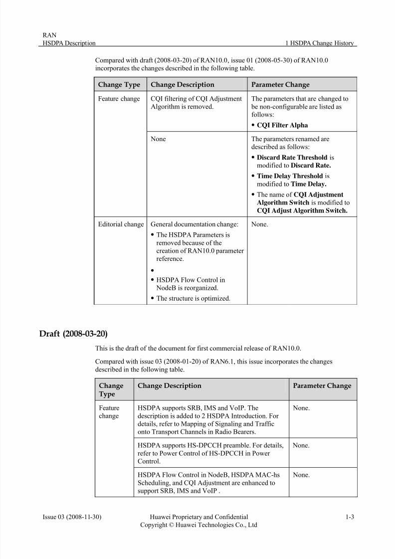
C raf , issue 0 10.0i ha llowing tabl
ompared with dncorporates the c
t (2008-03-20) of RAN10.0nges described in the fo
1 (2008-05-30) of RANe.
Change Description Parameter ChangeChange Type
CQI filtering of CQI AdjustmentAlgorithm is removed.
changed tore listed as
The parameters that are be non-configurable afollows:
z CQI Filter Alpha
Feature change
Nonede
z
rithm Switch is modified toCQI Adjust Algorithm Switch.
The parameters renamed arescribed as follows:
z Discard Rate Threshold ismodified to Discard Rate.
z Time Delay Threshold is
modified to Time Delay.
The name of CQI AdjustmentAlgo
Editorial change G
z
ause of thereation of RAN10.0 parameter
z
NodeB is reorganized.
z The structure is optimized.
None.eneral documentation change:
The HSDPA Parameters is
removed beccreference.
z HSDPA Flow Control in
Draft (2008-03-20)
or first commercial release of RAN10.0.
C with RAN6.1, this issue incorporad n the fo
This is the draft of the document f
ompared
escribed i
issue 03 (2008-01-20) of
llowing table.
tes the changes
Change
Type
Change Description Parameter Change
HSDPA supports SRB, IMS and VoIP. The
description is added to 2 HSDPA Introduction. For
None.
details, refer to Mapping of Signaling and Trafficonto Transport Channels in Radio Bearers.
HSDPA supports HS-DPCCH preamble. For details, None.
refer to Power Control of HS-DPCCH in Power Control.
Featurechange
B, HSDPA MAC-hs
anced to
None.HSDPA Flow Control in Node
Scheduling, and CQI Adjustment are enh
support SRB, IMS and VoIP .

7/27/2019 HSDPA Description(2008!11!30)
http://slidepdf.com/reader/full/hsdpa-description20081130 8/55
1 HSDPA Change History
RAN
HSDPA Description
1-4 Huawei Proprietary and Confidential
Copyright © Huawei Technologies Co., Ltd
Issue 03 (2008-11-30)
Change Change Description Parameter ChangeType
The CQI adjustment, maximum HARQ
retransmission, MAC-hs flow control policy, anscheduling policy are configure
dd on the basis of SPI.
None.
For details, refer to 4.1.2 QoS Management of Services Mapped on HSDPA.
CQI adjustment based on residual BLER is added for VoIP. For details, refer to CQI Adjustment. ad
m Switch
The parametersded are as follows:
z CQI Adjust
Algorith
z Residual Bler
Target
The scheduling algorithm is enhanced to support
SRB, IMS, and VoIP. The description is added to 4.3HSDPA MAC-hs Scheduling.
ad
hm Switch
The parameters
ded are as follows:
z EPF Schedule
Algorit
z MAC-hs Discard
timer
Unlimited capacity allocation policy is added to
enhance the flow coIMS, and SRB.
eter is consideredl. The description
w
Control Algorithm
Switch is added.ntrol algorithm to support VoIP,
Iub QoS management is added to
Iub shaping to provide
differentiated service. The SPIweight paramin flow contro
is added to 0
HSDPA Flow Control in NodeB.
The parameter Flo
Editorial
changez
z a
RAN Feature Configuration Guide.
z out HSDPA has beenmoved to Intra-Frequency Handover andInter-Frequency Handover.
None.General documentation change is as follows:
The document is reorganized.
Implementation information has been moved to
separate document. For information onimplementing HSDPA, refer to Configuring
HSDPA inz The Maintenance Information About HSDPA is
removed.
The handover information ab

7/27/2019 HSDPA Description(2008!11!30)
http://slidepdf.com/reader/full/hsdpa-description20081130 9/55
RAN
HSDPA Description 2 HSDPA Introduction
Issue 03 (2008-11-30) Huawei Proprietary and Confidential
Copyright © Huawei Technologies Co., Ltd
2-1
2 HSDPA Introduction
HSDPA (High Speed Downlink Packet Access) is an important feature of 3GPP R5. As a
wn aximum rate of 14.4
The
ng
z ed to improve spectral efficiency.
schedule User Equipments (UEs).
D rmance of UMTS network in the following aspects:
z /s.
erience with high-speed services, such as receiving
z and power
s
4.4 Mbit/s
r of users per cell: 64PS RABs
HSPA
z IMS signaling over HSPA
amble
do link (DL) high-speed data transmission solution, it has a theoretical mMbit/s on the Uu interface.
main features of HSDPA are as follows:
z Each subframe transmitted over the Uu interface has a size of 2 ms.
z The Hybrid Automatic Repeat Request (HARQ) and Adaptive Modulation and Codi(AMC) technologies are applied at the physical layer.
The high-order 16QAM modulation mode is us
z Both code division and time division are used to
HS PA improves the perfo
z Higher peak transmission rate in the downlink
The highest rate reaches 14.4 Mbit
z Shorter service delay
z HSDPA enhances the subscriber expe-mails and browsing web pages.
Higher utilization of DL codes
The HSDPA capabilities are as follows:
z Peak rate per cell: 14.4 Mbit/
z Peak rate per user: 1
z Maximum numbez Multiple RABs: 3
z SRB over HSDPA
z HSDPA over Iur
z VoIP over
z HS-DPCCH Pre
z F-DPCH
7/27/2019 HSDPA Description(2008!11!30)
http://slidepdf.com/reader/full/hsdpa-description20081130 10/55
2 HSDPA Introduction
RAN
HSDPA Description
2-2 Huawei Proprietary and Confidential
Copyright © Huawei Technologies Co., Ltd
Issue 03 (2008-11-30)
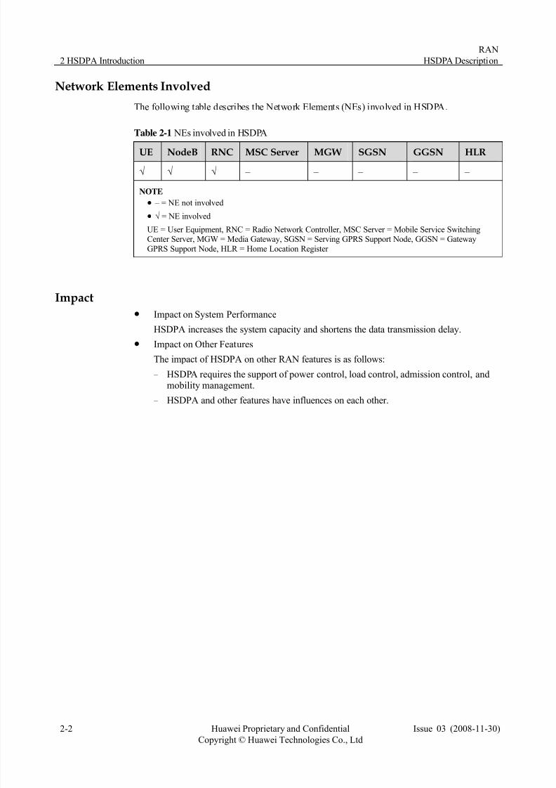
Network Elem
The foll le l E ed in
Table 2-1 NEs involved in HSDPA
ents Involved
owing tab describes the Network E ements (N s) involv HSDPA.
UE NodeB RNC MSC Server MGW SGSN GGSN HLR
√ – – – – √ √ –
N
z √ = NE involved
UE = User Equipment, RNC = Radio Network Controller, MSC Server = Mobile Service SwitchingCenter Server, MGW = Media Gateway, SGSN = Serving GPRS Support Node, GGSN = Gateway
GPRS Support Node, HLR = Home Location Register
OTE
z – = NE not involved
Impactz
z Impact on Other Feat
− HSDPA requires the support of power control, load control, admission control, andmobility management.
− HSDPA and other features have influences on each other.
Impact on System Performance
HSDPA increases the system capacity and shortens the data transmission delay.
ures
The impact of HSDPA on other RAN features is as follows:
7/27/2019 HSDPA Description(2008!11!30)
http://slidepdf.com/reader/full/hsdpa-description20081130 11/55
RAN
HSDPA Description 3 HSDPA Principles
Issue 03 (2008-11-30) Huawei Proprietary and Confidential
Copyright © Huawei Technologies Co., Ltd
3-1
3 HSDPA Principles
The principles of HSDPA cover the technical aspects of the feature:
z HSDPA Protocol Architecture
z HSDPA Physical layer
3.1 HSDPA Protocol Architecture
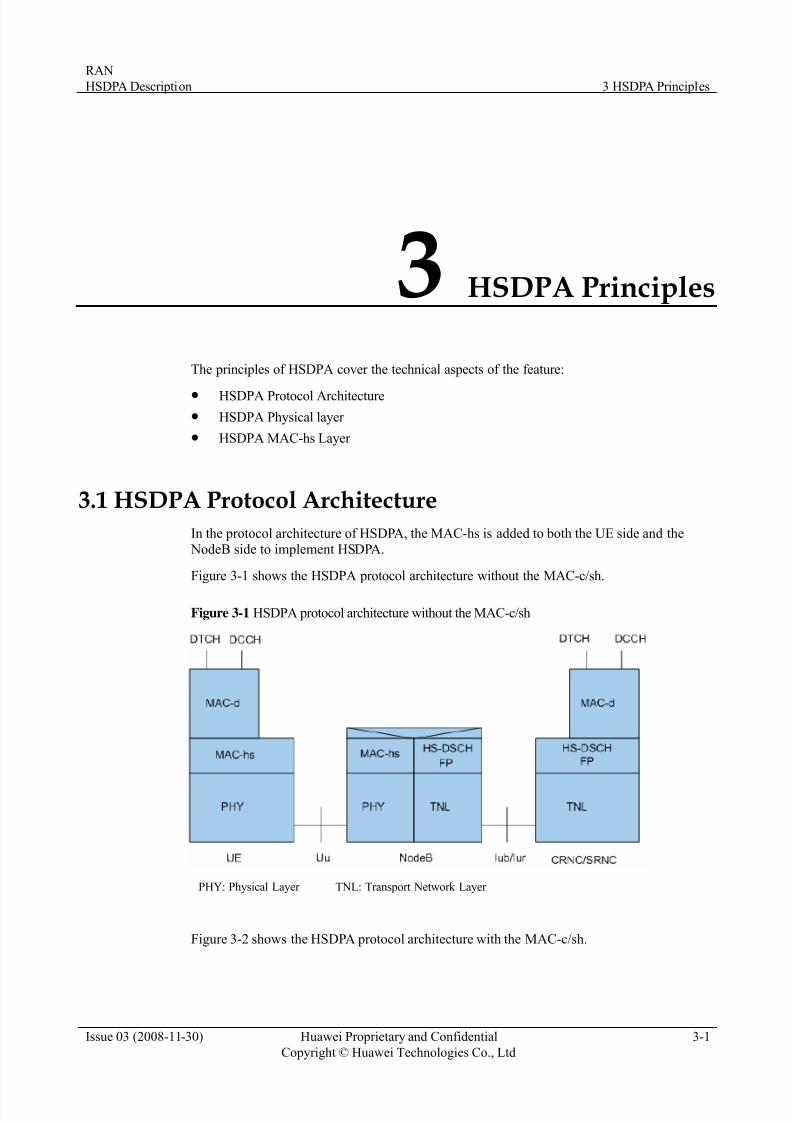
In the protocol architecture of HSDPA, the MAC-hs is added to both the UE side and the
z HSDPA MAC-hs Layer
NodeB side to implement HSDPA.
Figure 3-1 shows the HSDPA protocol architecture without the MAC-c/sh.
Figure 3-1 HSDPA protocol architecture without the MAC-c/sh
Figure 3-2 shows the HSDPA protocol architecture with the MAC-c/sh.
PHY: Physical Layer TNL: Transport Network Layer
7/27/2019 HSDPA Description(2008!11!30)
http://slidepdf.com/reader/full/hsdpa-description20081130 12/55
3 HSDPA Principles
RAN
HSDPA Description
3-2 Huawei Proprietary and Confidential
Copyright © Huawei Technologies Co., Ltd
Issue 03 (2008-11-30)
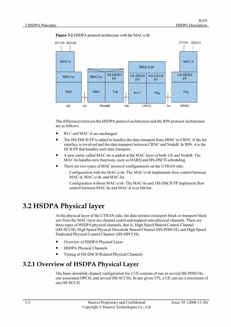
Figure 3-2 HSDPA protocol architecture with the MAC-c/sh
The differences between the HSDPA protocol architecture and the R99 protocol architectureare as follows:
z RLC and MAC-d are unchanged.
z The HS-DSCH FP is added to handles the data transport from SRNC to CRNC if the Iur
interface is involved and the data transport between CRNC and NodeB. In R99, it is theDCH FP that handles such data transport.
z A new entity called MAC-hs is added at the MAC layer of both UE and NodeB. TheMAC-hs handles new functions, such as HARQ and HS-DSCH scheduling.
z There are two types of MAC protocol configurations on the UTRAN side:
− Configuration with the MAC-c/sh: The MAC-c/sh implements flow control betweenMAC-d, MAC-c/sh, and MAC-hs.
− Configuration without MAC-c/sh: The MAC-hs and HS-DSCH FP implement flowcontrol between MAC-hs and MAC-d over Iub/Iur.
3.2 HSDPA Physical layer
At the physical layer of the UTRAN side, the data streams (transport block or transport block set) from the MAC layer are channel coded and mapped onto physical channels. There are
three types of HSDPA physical channels, that is, High Speed Shared Control Channel
(HS-SCCH), High Speed Physical Downlink Shared Channel (HS-PDSCH), and High SpeedDedicated Physical Control Channel (HS-DPCCH).
z Overview of HSDPA Physical Layer
z HSDPA Physical Channels
z Timing of HS-DSCH Related Physical Channels
3.2.1 Overview of HSDPA Physical Layer
The basic downlink channel configuration for a UE consists of one or several HS-PDSCHs,
one associated DPCH, and several HS-SCCHs. In any given TTI, a UE can use a maximum of one HS-SCCH.

7/27/2019 HSDPA Description(2008!11!30)
http://slidepdf.com/reader/full/hsdpa-description20081130 13/55
RAN
HSDPA Description 3 HSDPA Principles
Issue 03 (2008-11-30) Huawei Proprietary and Confidential
Copyright © Huawei Technologies Co., Ltd
3-3
Figure 3-3 Physical channels from the view of an HSDPA UE
When Fractional-Dedicated Physical Control Channel (F-DPCH) is configured, all RABs/SRBs are
carried on HS-DSCH. The associated DPCH is replaced with the F-DPCH and there is no DPDCH
The basic uplink channel configuration of HSDPA is the same as that of R99, except that one
HS-DPCCH is added for one UE.
Seen from the UE side, the processing at the HSDPA-related physical layer is as follows:
z In each TTI, the UE detects the HS-SCCH channel to check whether the UE is scheduledor not.
− If the UE is scheduled, it demodulates and decodes the data from HS-PDSCHsspecified by the related HS-SCCH. An ACK or NACK will be generated on the basis
of the decoding result of HS-PDSCHs and will be sent to the serving cell throughHS-DPCCH.
− If the UE is not scheduled, it does not demodulate or decode the data fromHS-PDSCHs.
z The channel quality indicator (CQI) is periodically reported through the HS-DPCCHregardless of whether the UE is scheduled. CQI is a key input for Transport Format andResource Combination (TFRC) selection and scheduling based on channel quality at theMAC-hs layer.
Seen from the UTRAN side, the processing at the HSDPA-related physical layer is as follows:
z Multiple UEs can be multiplexed in the code domain within an HS-DSCH TTI. This process is called code division in one TTI.
z The physical resources of HS-DSCH are time shared by all HS-DSCH UEs in the cell.
3.2.2 HSDPA Physical Channels
The HSDPA physical channels are as follows:
z HS-SCCH
z HS-PDSCH
z HS-DPCCH
HS-SCCH
The High Speed Shared Control Channel (HS-SCCH) is a downlink physical channel used to
carry downlink signaling related to High Speed Physical Downlink Shared Channel
(HS-PDSCH). The HS-SCCH has a fixed rate of 60 kbit/s (SF = 128). The following figure
shows the subframe structure of the HS-SCCH.

7/27/2019 HSDPA Description(2008!11!30)
http://slidepdf.com/reader/full/hsdpa-description20081130 14/55
3 HSDPA Principles
RAN
HSDPA Description
3-4 Huawei Proprietary and Confidential
Copyright © Huawei Technologies Co., Ltd
Issue 03 (2008-11-30)
Figure 3-4 Subframe structure of the HS-SCCH
The HS-SCCH transmits the following control information:
z HS-PDSCH channelization code set information
z HS-PDSCH modulation scheme information
z Transport block size information
z Hybrid ARQ process information
z Redundancy and constellation version
z New data indicator
z UE identify
HS-PDSCH
The High Speed Physical Downlink Shared Channel (HS-PDSCH) is used to carry the
HS-DSCH data. The HS-PDSCH SF can be 16 only. The modulation mode of HS-PDSCH isQPSK or 16QAM.
Each cell provides a maximum of 15 HS-PDSCH codes. The UE of category 10 supports amaximum of 15 HS-PDSCH codes and the 16QAM modulation mode, with the peak rate of
14.4 Mbit/s on the Uu interface.
Figure 3-5 shows the subframe structure of the HS-PDSCH.
Figure 3-5 Subframe structure of the HS-PDSCH
In the figure, M is the number of bits per modulation symbol.
7/27/2019 HSDPA Description(2008!11!30)
http://slidepdf.com/reader/full/hsdpa-description20081130 15/55
RAN
HSDPA Description 3 HSDPA Principles
Issue 03 (2008-11-30) Huawei Proprietary and Confidential
Copyright © Huawei Technologies Co., Ltd
3-5
z For QPSK, M = 2.
z For 16QAM, M = 4.
HS-DPCCH
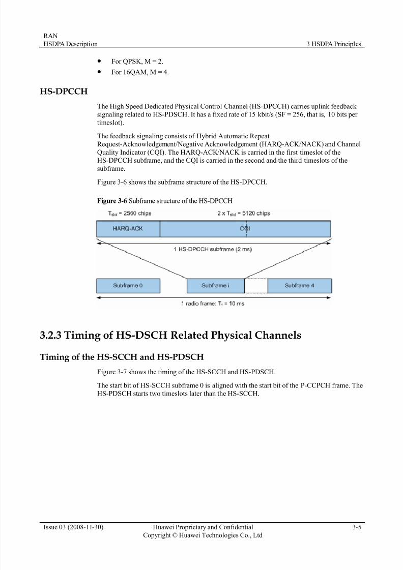
The High Speed Dedicated Physical Control Channel (HS-DPCCH) carries uplink feedback signaling related to HS-PDSCH. It has a fixed rate of 15 kbit/s (SF = 256, that is, 10 bits per
timeslot).
The feedback signaling consists of Hybrid Automatic RepeatRequest-Acknowledgement/Negative Acknowledgement (HARQ-ACK/NACK) and Channel
Quality Indicator (CQI). The HARQ-ACK/NACK is carried in the first timeslot of theHS-DPCCH subframe, and the CQI is carried in the second and the third timeslots of the
subframe.
Figure 3-6 shows the subframe structure of the HS-DPCCH.
Figure 3-6 Subframe structure of the HS-DPCCH
3.2.3 Timing of HS-DSCH Related Physical Channels
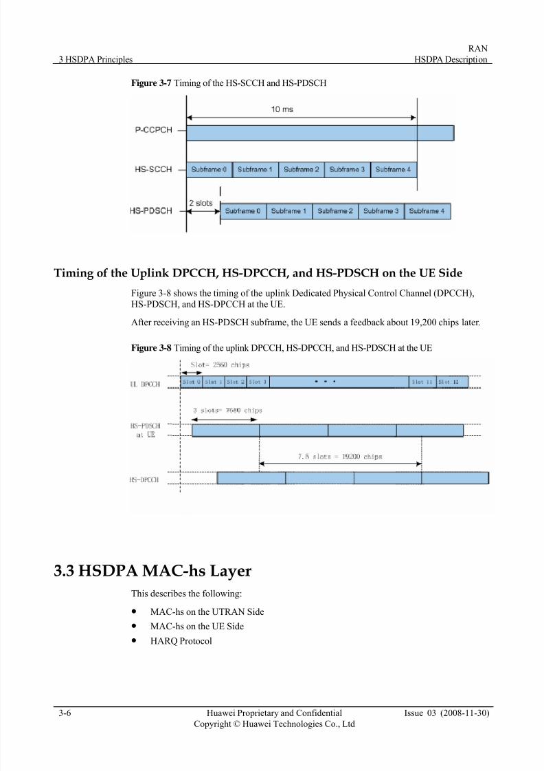
Timing of the HS-SCCH and HS-PDSCH
Figure 3-7 shows the timing of the HS-SCCH and HS-PDSCH.
The start bit of HS-SCCH subframe 0 is aligned with the start bit of the P-CCPCH frame. TheHS-PDSCH starts two timeslots later than the HS-SCCH.
7/27/2019 HSDPA Description(2008!11!30)
http://slidepdf.com/reader/full/hsdpa-description20081130 16/55
3 HSDPA Principles
RAN
HSDPA Description
3-6 Huawei Proprietary and Confidential
Copyright © Huawei Technologies Co., Ltd
Issue 03 (2008-11-30)
Figure 3-7 Timing of the HS-SCCH and HS-PDSCH
Timing of the Uplink DPCCH, HS-DPCCH, and HS-PDSCH on the UE Side
Figure 3-8 shows the timing of the uplink Dedicated Physical Control Channel (DPCCH),
HS-PDSCH, and HS-DPCCH at the UE.
After receiving an HS-PDSCH subframe, the UE sends a feedback about 19,200 chips later.
Figure 3-8 Timing of the uplink DPCCH, HS-DPCCH, and HS-PDSCH at the UE
3.3 HSDPA MAC-hs Layer
This describes the following:
z MAC-hs on the UTRAN Side
z MAC-hs on the UE Side
z HARQ Protocol

7/27/2019 HSDPA Description(2008!11!30)
http://slidepdf.com/reader/full/hsdpa-description20081130 17/55
RAN
HSDPA Description 3 HSDPA Principles
Issue 03 (2008-11-30) Huawei Proprietary and Confidential
Copyright © Huawei Technologies Co., Ltd
3-7
3.3.1 MAC-hs on the UTRAN Side
The MAC-hs on the UTRAN side manages the physical resources allocated to HS-DSCH.
The MAC-hs consists of the following four different functional entities:
z Flow control
z Scheduling
z TFRC selection: Transport Format and Resource Combination selection
z HARQ: Hybrid Automatic Repeat reQuest
Figure 3-9 shows the MAC-hs architecture on the UTRAN side.
Figure 3-9 MAC-hs architecture on the UTRAN side
The flow control entity controls the HSDPA data flow between RNC and NodeB.
z Purpose: to reduce the transmission time of HSDPA data on the UTRAN side and to
reduce the data discarded and retransmitted when the Iub interface or Uu interface iscongested.
z The transmission capabilities of the Uu interface and Iub interface are taken into accountin a dynamic manner in the flow control. For details of flow control, refer to 4.2 HSDPAFlow Control in NodeB.
The scheduling entity handles the priority of the queues and schedules the priority queues or
NACK HARQ processes of the HS-DSCH UEs in a cell to be transmitted on the HS-DSCH
related physical channels in each TTI.
7/27/2019 HSDPA Description(2008!11!30)
http://slidepdf.com/reader/full/hsdpa-description20081130 18/55
3 HSDPA Principles
RAN
HSDPA Description
3-8 Huawei Proprietary and Confidential
Copyright © Huawei Technologies Co., Ltd
Issue 03 (2008-11-30)
z Purpose: to achieve considerable cell throughput capability and to satisfy user experience.
z The selection is implemented through the scheduling algorithm based on channel qualityor QoS. For details of scheduling, refer to 4.3 HSDPA MAC-hs Scheduling.
The HARQ entity handles the HARQ protocol for each HS-DSCH UE.
z Each HS-DSCH UE has one HARQ entity on the MAC-hs of the UTRAN side to handlethe HARQ functionality.
z One HARQ entity can support multiple instances (HARQ processes) of stop and wait
HARQ protocols. Based on the status reports from HS-DPCCH, a new transmission or
retransmission is determined. For details of HARQ protocol, refer to 3.3.3 HARQProtocol.
The TFRC selection entity selects an appropriate transport format and resource for the data to
be transmitted on HS-DSCH.
z The transport format includes the transport block size and modulation scheme. The
resource includes the power resource and code resource of HS-PDSCH.
z Transport Format and Resource Combination (TFRC) for each UE is channel quality
based, where AMC is the key technique. For details of TFRC selection, refer to 4.4HSDPA TFRC Selection.
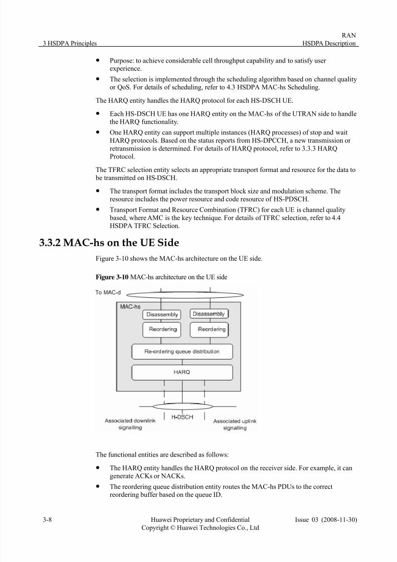
3.3.2 MAC-hs on the UE Side
Figure 3-10 shows the MAC-hs architecture on the UE side.
Figure 3-10 MAC-hs architecture on the UE side
The functional entities are described as follows:
z The HARQ entity handles the HARQ protocol on the receiver side. For example, it cangenerate ACKs or NACKs.
z The reordering queue distribution entity routes the MAC-hs PDUs to the correct
reordering buffer based on the queue ID.

7/27/2019 HSDPA Description(2008!11!30)
http://slidepdf.com/reader/full/hsdpa-description20081130 19/55
RAN
HSDPA Description 3 HSDPA Principles
Issue 03 (2008-11-30) Huawei Proprietary and Confidential
Copyright © Huawei Technologies Co., Ltd
3-9
z The reordering entity reorders the received MAC-hs PDUs according to their transmission sequence number (TSN) and the TSN may be out of sequence because of parallel HARQ processes. For each queue ID, one reordering entity is configured on theUE.
z
The disassembly entity extracts the MAC-d PDUs from the MAC-hs PDUs and deliversthem to the higher layer.
3.3.3 HARQ Protocol
The HARQ protocol is based on the stop and wait ARQ scheme, and supports chasecombining and incremental redundancy combining.
Figure 3-11 shows the principle of HARQ protocol.
Figure 3-11 Principle of the HARQ protocol
The following topic describes the protocol by taking one UE as an example.
z In a given TTI, the NodeB initiates data transmission of a new transport block (TB) tothe UE.
Before transmission over the Uu interface, the TB is channel coded at the physical layer,where systematic and parity bits are generated.
z Because of errors in the Uu interface, the receiver UE cannot decode the TB successfully.
Therefore, it generates an HARQ-NACK message and sends it to the NodeB through the
uplink HS-DPCCH.z The NodeB retransmits the TB after receiving the NACK from the UE.
z The channel coding bits in original transmission and subsequent retransmissions are buffered on the UE and then are soft-combined to improve the probability of successfully decoding the TB.
The ARQ combining scheme is based on incremental redundancy. Different sets of channelcoding bits of the TB can be chosen in the retransmission. Chase combining is considered to
be a particular case of incremental redundancy, in which the same systematic and parity bitsas those used in the initial transmission are retransmitted.
Compared with retransmission at the RLC layer, HARQ has the following benefits:

7/27/2019 HSDPA Description(2008!11!30)
http://slidepdf.com/reader/full/hsdpa-description20081130 20/55
3 HSDPA Principles
RAN
HSDPA Description
3-10 Huawei Proprietary and Confidential
Copyright © Huawei Technologies Co., Ltd
Issue 03 (2008-11-30)
z The round trip time at the physical layer is approximately 12 ms, much shorter than thatat the RLC layer. The round trip time at the RLC layer may reach hundreds of milliseconds.
z Soft combining improves the efficiency of the physical layer resource.
The round trip time at the physical layer is 12 ms. Therefore, it is necessary for one UE tohave multiple parallel instances (HARQ processes) of the stop and wait HARQ protocol toincrease the Uu interface throughput.
One issue in the receiver caused by multiple HARQ processes is that, in a specific time
window, the TBs may arrive out of sequence. Therefore, it is necessary to have reorderingfunctionality on the receiver side.

7/27/2019 HSDPA Description(2008!11!30)
http://slidepdf.com/reader/full/hsdpa-description20081130 21/55
RAN
HSDPA Description 4 HSDPA Algorithms
Issue 03 (2008-11-30) Huawei Proprietary and Confidential
Copyright © Huawei Technologies Co., Ltd
4-1
4 HSDPA Algorithms
Th algorithms of HSDPA are as foe llows:
ted Algorithms
z HSDPA Power Resource Management
z HSDPA Code Resource Management
4.1 Overview of HSDPA-Related Algorithmsz HSDPA-Related Algorithms Involved in a Call Process
z QoS Management of Services Mapped on HSDPA
z Overview of HSDPA-Rela
z HSDPA Flow Control in NodeB
z HSDPA MAC-hs Scheduling
z HSDPA TFRC Selection
z Other HSDPA Related Algorithms
7/27/2019 HSDPA Description(2008!11!30)
http://slidepdf.com/reader/full/hsdpa-description20081130 22/55
4 HSDPA Algorithms
RAN
HSDPA Description
4-2 Huawei Proprietary and Confidential
Copyright © Huawei Technologies Co., Ltd
Issue 03 (2008-11-30)
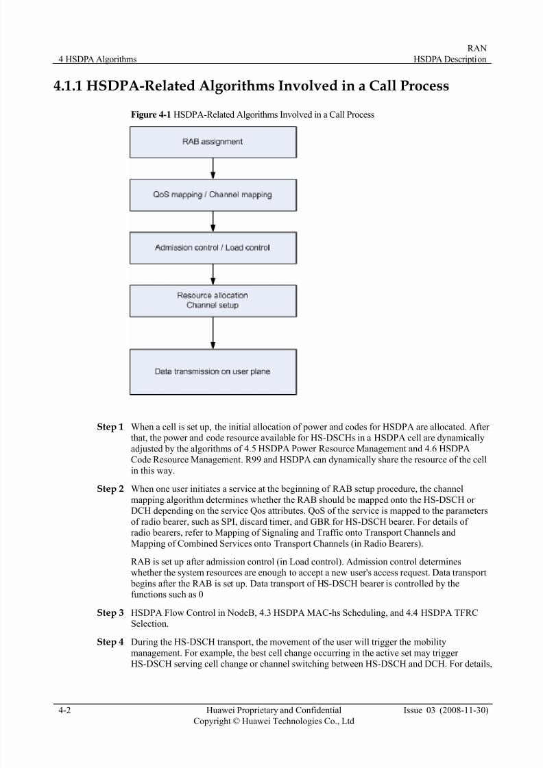
4.1.1 HSDPA-Related Algorithms Involved in a Call Process
Figure 4-1 HSDPA-Related Algorithms Involved in a Call Process
Step 1 When a cell is set up, the initial allocation of power and codes for HSDPA are allocated. After that, the power and code resource available for HS-DSCHs in a HSDPA cell are dynamically
adjusted by the algorithms of 4.5 HSDPA Power Resource Management and 4.6 HSDPA
Code Resource Management. R99 and HSDPA can dynamically share the resource of the cell
in this way.
Step 2 When one user initiates a service at the beginning of RAB setup procedure, the channel
mapping algorithm determines whether the RAB should be mapped onto the HS-DSCH or DCH depending on the service Qos attributes. QoS of the service is mapped to the parameters
of radio bearer, such as SPI, discard timer, and GBR for HS-DSCH bearer. For details of radio bearers, refer to Mapping of Signaling and Traffic onto Transport Channels and
Mapping of Combined Services onto Transport Channels (in Radio Bearers).
RAB is set up after admission control (in Load control). Admission control determineswhether the system resources are enough to accept a new user's access request. Data transport
begins after the RAB is set up. Data transport of HS-DSCH bearer is controlled by thefunctions such as 0
Step 3 HSDPA Flow Control in NodeB, 4.3 HSDPA MAC-hs Scheduling, and 4.4 HSDPA TFRCSelection.
Step 4 During the HS-DSCH transport, the movement of the user will trigger the mobility
management. For example, the best cell change occurring in the active set may trigger HS-DSCH serving cell change or channel switching between HS-DSCH and DCH. For details,
7/27/2019 HSDPA Description(2008!11!30)
http://slidepdf.com/reader/full/hsdpa-description20081130 23/55
RAN
HSDPA Description 4 HSDPA Algorithms
Issue 03 (2008-11-30) Huawei Proprietary and Confidential
Copyright © Huawei Technologies Co., Ltd
4-3
refer to Intra-Frequency Handover, Inter-Frequency Handover, and Inter-RAT Handover Description.
Step 5 Load control also manages the overload situation besides admission control. Load control
needs to reserve enough resource to ensure the QoS of the service. HS-DSCH scheduling
provides the measurement of GBP, PBR, and DL transmit power and takes it as the input toload control.
Step 6 After HSDPA is introduced, there is one more UE state, that is, CELL_DCH (HS-DSCH).Channel switching between HS-DSCH and DCH and channel switching between HS-DSCHand FACH are introduced. The channel switching may be triggered by mobility or change of
traffic volume. For details, refer to 4.7.6 HSDPA Channel Switching.
----End
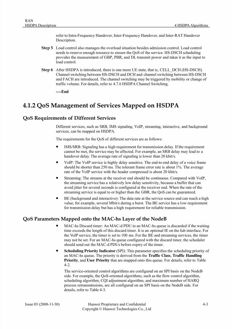
4.1.2 QoS Management of Services Mapped on HSDPA
QoS Requirements of Different Services
Different services, such as SRB, IMS signaling, VoIP, streaming, interactive, and background
services, can be mapped on HSDPA.
The requirements for the QoS of different services are as follows:
z IMS/SRB: Signaling has a high requirement for transmission delay. If the requirementcannot be met, the service may be affected. For example, an SRB delay may lead to a
handover delay. The average rate of signaling is lower than 20 kbit/s.
z VoIP: The VoIP service is highly delay sensitive. The end-to-end delay of a voice frameshould be shorter than 250 ms. The tolerant frame error rate is about 1%. The average
rate of the VoIP service with the header compressed is about 20 kbit/s.z Streaming: The streams at the receiver end should be continuous. Compared with VoIP,
the streaming service has a relatively low delay sensitivity, because a buffer that canavoid jitter for several seconds is configured at the receiver end. When the rate of the
streaming service is equal to or higher than the GBR, the QoS can be guaranteed.
z BE (background and interactive): The data rate at the service source end can reach a highvalue, for example, several Mbit/s during a burst. The BE service has a low requirementfor transmission delay but has a high requirement for reliable transmission.
QoS Parameters Mapped onto the MAC-hs Layer of the NodeBz MAC-hs Discard timer: An MAC-d PDU in an MAC-hs queue is discarded if the waiting
time exceeds the length of this discard timer. It is an optional IE on the Iub interface. For the VoIP service, the timer is set to 100 ms. For the BE and streaming services, the timer
may not be set. For an MAC-hs queue configured with the discard timer, the scheduler should send out the MAC-d PDUs before expiry of the timer.
z Scheduling Priority Indicator (SPI): This parameter specifies the scheduling priority of an MAC-hs queue. The priority is derived from the Traffic Class, Traffic Handling
Priority, and User Priority that are mapped onto this queue. For details, refer to Table
4-2.
The service-oriented control algorithms are configured on an SPI basis on the NodeB
side. For example, the QoS-oriented algorithms, such as the flow control algorithm,scheduling algorithm, CQI adjustment algorithm, and maximum number of HARQ process retransmissions, are all configured on an SPI basis on the NodeB side. For details, refer to Table 4-3.

7/27/2019 HSDPA Description(2008!11!30)
http://slidepdf.com/reader/full/hsdpa-description20081130 24/55
4 HSDPA Algorithms
RAN
HSDPA Description
4-4 Huawei Proprietary and Confidential
Copyright © Huawei Technologies Co., Ltd
Issue 03 (2008-11-30)
− For details of setting EPF Schedule Algorithm Switch, refer to 4.3 HSDPA MAC-hsScheduling.
For details of setting Flow Control Algorithm Switch, refer to 0
− HSDPA Flow Control in NodeB.
The user priority–oriented parameters are also configured on an SPI basis on the NodeBside. For example, the weight factor corresponding to the user priority is named Weight
of SPI on the NodeB side. For details, refer to Table 4-2.
z Guaranteed Bit Rate (GBR): It is configured on an MAC-hs queue basis. For the
streaming service, the GBR specifies the rate that can meet the requirement of the user
for viewing and the GBR of a queue is determined by the NAS. For the BE service, theGBR specifies the required minimum rate for the service of the users in the RAN. The
GBR of a BE service user is set through the SET USERGBR command on the RNC side.The setting is based on the user priority, namely, gold user, silver user, or copper user.
Services with different QoS requirements require different QoS guarantee policies. For example, the VoIP service has a high requirement for delay. To limit the delay caused by
flow control or scheduling within a proper range, the algorithm grants the VoIP queue a priority to occupy resources first. The streaming service has a high requirement for GBR.
Therefore, the scheduling and flow control algorithms guarantee that the average rate of the service is not lower than the GBR during Iub traffic distribution and Uu resources
allocation. The BE service has a high requirement for reliability, which can be achievedthrough more retransmissions on the Uu interface.
Mapping of the Scheduling Priority Indicator
Figure 4-2 Mapping of the Scheduling Priority Indicator
z Scheduling Priority Indicator (SPI) is the relative priority of the HS-DSCH FP data
frame and the SDUs included. The SPI is set according to the Traffic Class (TC),Traffic Handling Priority (THP) of the interactive service, and User Priority. The SPIis set on the RNC LMT and sent to the NodeB through NBAP signaling.
z User Priority is determined by the Allocation Retention Priority (ARP), as listed in the
following table.
Table 4-1 Mapping of ARP to user priority
ARP 0 1 2 3 4 5 6 7 8 9 10 11 12 13 14 15
7/27/2019 HSDPA Description(2008!11!30)
http://slidepdf.com/reader/full/hsdpa-description20081130 25/55
RAN
HSDPA Description 4 HSDPA Algorithms
Issue 03 (2008-11-30) Huawei Proprietary and Confidential
Copyright © Huawei Technologies Co., Ltd
4-5
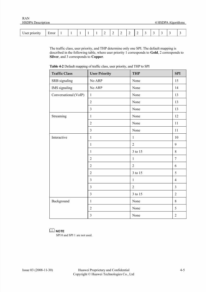
User priority Error 1 1 1 1 1 2 2 2 2 2 3 3 3 3 3
The traffic class, user priority, and THP determine only one SPI. The default mapping isdescribed in the following table, where user priority 1 corresponds to Gold, 2 corresponds toSilver, and 3 corresponds to Copper.
Table 4-2 Default mapping of traffic class, user priority, and THP to SPI
User Priority THP SPITraffic Class
SRB signaling No ARP None 15
IMS signaling No ARP None 14
1 None 13
2 None 13
Conversational (VoIP)
3 None 13
1 None 12
2 None 11
Streaming
3 None 11
1 1 10
1 2 9
1 3 to 15 8
2 1 7
2 2 6
2 3 to 15 5
3 1 4
3 2 3
Interactive
3 3 to 15 2
1 None 8
2 None 5
Background
3 None 2
SPI 0 and SPI 1 are not used.
7/27/2019 HSDPA Description(2008!11!30)
http://slidepdf.com/reader/full/hsdpa-description20081130 26/55
4 HSDPA Algorithms
RAN
HSDPA Description
4-6 Huawei Proprietary and Confidential
Copyright © Huawei Technologies Co., Ltd
Issue 03 (2008-11-30)
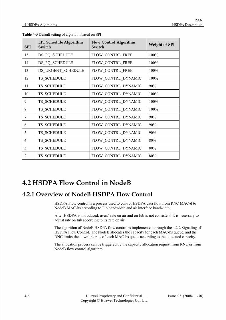
Table 4-3 Default setting of algorithm based on SPI
EPF Schedule AlgorithmSwitch
Flow Control AlgorithmSwitch
Weight of SPISPI
15 DS_PQ_SCHEDULE FLOW_CONTRL_FREE 100%
14 DS_PQ_SCHEDULE FLOW_CONTRL_FREE 100%
13 DS_URGENT_SCHEDULE FLOW_CONTRL_FREE 100%
12 TS_SCHEDULE FLOW_CONTRL_DYNAMIC 100%
11 TS_SCHEDULE FLOW_CONTRL_DYNAMIC 90%
10 TS_SCHEDULE FLOW_CONTRL_DYNAMIC 100%
9 TS_SCHEDULE FLOW_CONTRL_DYNAMIC 100%
8 TS_SCHEDULE FLOW_CONTRL_DYNAMIC 100%
7 TS_SCHEDULE FLOW_CONTRL_DYNAMIC 90%
6 TS_SCHEDULE FLOW_CONTRL_DYNAMIC 90%
5 TS_SCHEDULE FLOW_CONTRL_DYNAMIC 90%
4 TS_SCHEDULE FLOW_CONTRL_DYNAMIC 80%
3 TS_SCHEDULE FLOW_CONTRL_DYNAMIC 80%
2 TS_SCHEDULE FLOW_CONTRL_DYNAMIC 80%
4.2 HSDPA Flow Control in NodeB
4.2.1 Overview of NodeB HSDPA Flow Control
HSDPA Flow control is a process used to control HSDPA data flow from RNC MAC-d to
NodeB MAC-hs according to Iub bandwidth and air interface bandwidth.
After HSDPA is introduced, users’ rate on air and on Iub is not consistent. It is necessary to
adjust rate on Iub according to its rate on air.
The algorithm of NodeB HSDPA flow control is implemented through the 4.2.2 Signaling of HSDPA Flow Control. The NodeB allocates the capacity for each MAC-hs queue, and the
RNC limits the downlink rate of each MAC-hs queue according to the allocated capacity.
The allocation process can be triggered by the capacity allocation request from RNC or from
NodeB flow control algorithm.
7/27/2019 HSDPA Description(2008!11!30)
http://slidepdf.com/reader/full/hsdpa-description20081130 27/55
RAN
HSDPA Description 4 HSDPA Algorithms
Issue 03 (2008-11-30) Huawei Proprietary and Confidential
Copyright © Huawei Technologies Co., Ltd
4-7
Figure 4-3 Structure of flow control algorithm
NodeB and RNC can provide flow control functions. In NodeB, there are two types of flow
control policies.
z Flow control free
z Dynamic flow control
Dynamic flow control has three methods.
z No shaping
z Shaping without adaptive Iub bandwidth.
z Shaping with adaptive Iub bandwidth
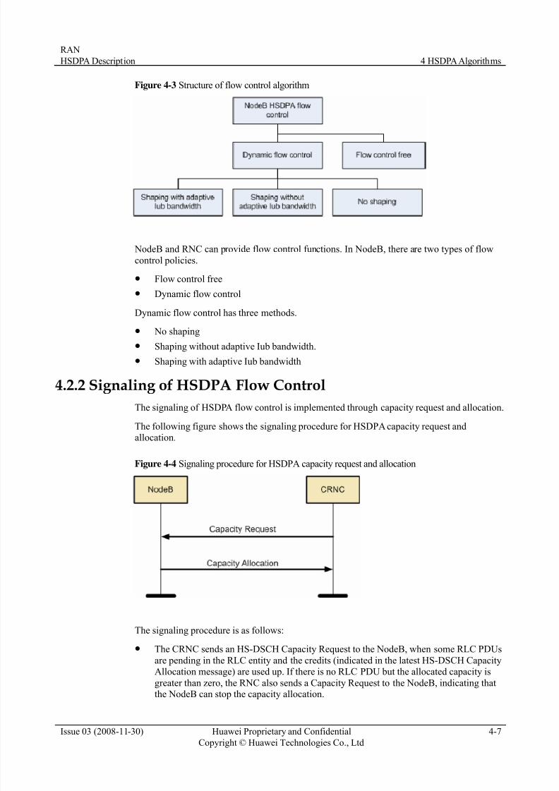
4.2.2 Signaling of HSDPA Flow Control
The signaling of HSDPA flow control is implemented through capacity request and allocation.
The following figure shows the signaling procedure for HSDPA capacity request andallocation.
Figure 4-4 Signaling procedure for HSDPA capacity request and allocation
The signaling procedure is as follows:
z The CRNC sends an HS-DSCH Capacity Request to the NodeB, when some RLC PDUs
are pending in the RLC entity and the credits (indicated in the latest HS-DSCH CapacityAllocation message) are used up. If there is no RLC PDU but the allocated capacity is
greater than zero, the RNC also sends a Capacity Request to the NodeB, indicating that
the NodeB can stop the capacity allocation.

7/27/2019 HSDPA Description(2008!11!30)
http://slidepdf.com/reader/full/hsdpa-description20081130 28/55
4 HSDPA Algorithms
RAN
HSDPA Description
4-8 Huawei Proprietary and Confidential
Copyright © Huawei Technologies Co., Ltd
Issue 03 (2008-11-30)
z The NodeB sends an HS-DSCH Capacity Allocation message to the CRNC as theresponse to the HS-DSCH capacity request or to the requirement of the Iub HSDPA flowcontrol algorithm.
The following figure shows the structure of the capacity request frame. The frame includes
the queue priority and the data buffer size at the RNC RLC layer.
Figure 4-5 Structure of the capacity request frame
The following figure shows the structure of the capacity allocation frame.
Figure 4-6 Structure of the capacity allocation frame
In the HS-DSCH Interval, the user can send a maximum number of HS-DSCH CreditsMAC-d PDUs. The PDU size is limited by Maximum MAC-d PDU Length. The user can
repeat the HS-DSCH Interval in the period defined by HS-DSCH repetition period.
z CmCH-PI: Scheduling Priority Indicator (SPI) of the queue.
z HS-DSCH Interval: time interval during which the HS-DSCH Credits granted in theHS-DSCH CAPACITY ALLOCATION control frame can be used.

7/27/2019 HSDPA Description(2008!11!30)
http://slidepdf.com/reader/full/hsdpa-description20081130 29/55
RAN
HSDPA Description 4 HSDPA Algorithms
Issue 03 (2008-11-30) Huawei Proprietary and Confidential
Copyright © Huawei Technologies Co., Ltd
4-9
z HS-DSCH Credits: number of MAC-d PDUs that a CRNC can transmit during anHS-DSCH Interval granted in the HS-DSCH CAPACITY ALLOCATION control frame.
z Maximum MAC-d PDU Length: maximum PDU size among the MAC-d PDU sizesconfigured in the NBAP messages.
z HS-DSCH repetition period: number of subsequent intervals during which the HS-DSCHCredits IE granted in the HS-DSCH CAPACITY ALLOCATION control frame can beused and the value 0 means that there is no limit to the repetition period.
4.2.3 Flow Control Policies
Generally, the NodeB allocating the capacity to a MAC-hs queue considers the output rate onthe Uu interface and Iub available bandwidth. For different QoS requirements, the NodeB
uses different flow control policies, namely, flow control free and dynamic flow control.
The flow control policies are based on SPI and are configured through the Flow Control
Algorithm Switch parameter. For details of recommended policy of flow control based on
SPI, refer to 4.1.2 QoS Management of Services Mapped on HSDPA.
Flow Control Free Policy
After the HS-DSCH bearer is set up, the NodeB sends a capacity allocation message to the
RNC, indicating that the DL traffic of the new MAC-hs queue is not limited and the RNC
MAC-d can send data as much as required. The allocation keeps unchanged for the service.
The policy of no flow control policy is applied only to VoIP, IMS, and SRB, for these services
are delay sensitive and have a relative low rate.
Dynamic Flow Control Policy
Dynamic flow control is mainly applied to MAC-hs queues of BE service, for theses servicesare not delay sensitive, the rate varies in a wide range, and will reach a high rate during a
burst.
Dynamic flow control is also applied to MAC-hs queues of streaming service, for streaming
service has a relative high rate and may result in congestion on Uu.
This section mainly describes the method of shaping with adaptive Iub bandwidth of dynamicflow control policy. Other two methods are similar to shaping with adaptive Iub bandwidth,
except that the functions of shaping or Iub adaptive bandwidth is ignored.
Dynamic flow control process of Shaping with adaptive Iub bandwidth is as follows:
Step 1 The congestion status of the transport network is reflected to NodeB through DRT and FSN.The NodeB adaptively adjusts the Iub bandwidth available for HSDPA based on the
congestion detection.
Step 2 Depending on the available bandwidth and rate on air interface, the NodeB allocates
bandwidth to HSDPA users and performs traffic shaping (Iub shaping) to avoid congestion
and packet loss over the Iub interface.
Step 3 The RNC limits the flow of HS-DSCH data frames for each MAC-hs queue according to the
HS-DSCH capacity allocation.
----End

7/27/2019 HSDPA Description(2008!11!30)
http://slidepdf.com/reader/full/hsdpa-description20081130 30/55
4 HSDPA Algorithms
RAN
HSDPA Description
4-10 Huawei Proprietary and Confidential
Copyright © Huawei Technologies Co., Ltd
Issue 03 (2008-11-30)
Figure 4-7 Dynamic flow control algorithm structure
Dynamic flow control policy consists of the following modules:
z Adaptive capacity allocation
NodeB adaptively allocates capacity to an MAC-hs queue based on its rate on air
interface.
Capacity means how much data RNC can send to NodeB in an interval.
z Congestion control on Iub
The total flow of all the MAC-hs queues should not exceed the available Iub bandwidthto avoid congestion on Iub.
RNC provides the function of backpressure to avoid Iub congestion. For details, see
Transmission Resource Management Description.
NodeB provides the following functions to avoid Iub congestion:
− Adaptive adjustment of Iub bandwidth
NodeB periodically detects Iub congestion and adaptively adjusts the available Iub
bandwidth according to the Iub state.
− Iub shaping
Iub shaping is used to allocate Iub bandwidth to every MAC-hs queue based on the
available Iub bandwidth and ensure the total flow of the queues does not exceed theavailable Iub bandwidth. Thus, congestion control is achieved on the Iub interface,which increases the bandwidth usage and avoids overload.
Dynamic flow control policy is configured through the Hsdpa Switch.
z If the switch is set to STATIC_BW_SHAPING, based on the configured Iub bandwidthand the bandwidth occupied by R99 users, traffic is allocated to HSDPA users when the physical bandwidth restriction is taken into account.

7/27/2019 HSDPA Description(2008!11!30)
http://slidepdf.com/reader/full/hsdpa-description20081130 31/55
RAN
HSDPA Description 4 HSDPA Algorithms
Issue 03 (2008-11-30) Huawei Proprietary and Confidential
Copyright © Huawei Technologies Co., Ltd
4-11
z If the switch is set to DYNAMIC_BW_SHAPING, according to the flow control of STATIC_BW_SHAPING, traffic is allocated to HSDPA users when the delay and packetloss on the Iub interface are taken into account. The RNC use the R6 switch to perform
this function. It is recommended that the RNC in compliance with R6 should performthis function.
z If the switch is set to NO_BW_SHAPING, the NodeB does not allocate bandwidth
according to the configuration or delay on the Iub interface. The RNC allocates the bandwidth according to the bandwidth on the Uu interface reported by the NodeB. To
perform this function, the reverse flow control switch must be enabled by the RNC. Thelink is not congested when the delay is lower than this threshold. The link is notcongested when frame loss ratio is no higher than this threshold.
z If the switch is set to BW_SHAPING_ONOFF_TOGGLE, if
BW_SHAPING_ONOFF_TOGGLE is selected, the system automatically selectsDYNAMIC_BW_SHAPING or NO_BW_SHAPING on the basis of the NodeB
congestion detection mechanism. In other words, DYNAMIC_BW_SHAPING isselected when congestion is detected; NO_BW_SHAPING is selected when there is no
congestion within a specific time.
BW_SHAPING_ONOFF_TOGGLE, DYNAMIC_BW_SHAPING, and NO_BW_SHAPING are flowcontrol strategies applied at the NodeB part.
4.2.4 Adaptive Capacity Allocation Based on Uu Rate
NodeB adaptively allocates capacity to an MAC-hs queue based on its rate on air interface
(Uu).
The Uu interface transmission rate of the MAC-hs queue varies dynamically with several
factors, such as the channel quality of the UE and activities of other users in the system.
It makes sense to keep the queue occupancy in a reasonable level in order to reduce datatransmission delay, L2 layer signal delay, and discarding as the result of priority queuecongestion or reset during handover. In this sense, the functionality is called capacity
allocation adaptive to Uu interface bit rate, where capacity allocation for each priority queueis based on the Uu interface bit rate and the buffer occupancy level.
The Iub bandwidth allocation is based only on the rate of each queue on the Uu interface.
z If there is not enough data in the queue, a wide bandwidth is allocated.
z If there is enough data in the queue, the bandwidth that is close to the rate on the Uuinterface is allocated.
z If there is too much data in the queue, a narrow bandwidth or no bandwidth is allocated.
Whether there is enough data in the queue is judged by the time to send all the data in the priority queue with the current Uu rate.
4.2.5 Iub Shaping
The allocation of the available Iub bandwidth to the MAC-hs queues is called Iub shaping.The available Iub bandwidth is from the algorithm of Adaptive Adjustment of Available
HSDPA Bandwidth. Iub shaping ensures that the total flow of the queues does not exceed theavailable Iub bandwidth.
z If the resource on the Uu interface is the bottleneck, the algorithm allocates the Iub
bandwidth to MAC-hs queue based rate on the Uu interface. The rate on the Uu interfaceis from Adaptive Capacity Allocation Based on Uu Rate.
7/27/2019 HSDPA Description(2008!11!30)
http://slidepdf.com/reader/full/hsdpa-description20081130 32/55
4 HSDPA Algorithms
RAN
HSDPA Description
4-12 Huawei Proprietary and Confidential
Copyright © Huawei Technologies Co., Ltd
Issue 03 (2008-11-30)
z If the resource on the Iub interface is the bottleneck, the bandwidth allocation is based onthe rate on the Uu interface and the available Iub bandwidth.
− The algorithm considers the following factors of the MAC-hs queues: the bit rateallocated by Adaptive Capacity Allocation Based on Uu Rate, NodeB buffer
occupancy, RNC buffer occupancy, and the bottleneck bandwidth available for HSDPA on the Iub interface from Adaptive Adjustment of Available HSDPABandwidth.
− First, Iub resource for GBR is allocated. That is, the algorithm first considers the
basic requirements for guaranteeing the user experience.
− Then, the algorithm considers the requirement for user differentiation. For all theusers in the cell, the scheduler intends to allocate the Iub resource in proportion totheir Weight of SPI, which is based on user priorities, eg. gold, silver and copper.
User priority differentiation is implemented when Iub is the bottleneck. The gold, silver, and
copper users obtain the resources in proportion to their priority weight factors (Weight of
SPI). In addition, the resources necessary for guaranteeing the GBR must be allocated first
before the resource allocation based on the proportion.z For example, assume that Iub is the bottleneck, gold, silver and copper users are using
FTP service simultaneously. Then the Iub throughputs of gold, silver and copper usersare in proportion to the ratio of their SPI weights.
z For another example, assume that the silver user is using HTTP service, the gold and thecopper user are using FTP service, and the silver user is reading the HTTP page. Then
the gold and copper users share the Iub resource and the Iub throughput of the gold andcopper users are in proportion to the ratio of their SPI weight.
4.2.6 Adaptive Adjustment of Available HSDPA Bandwidth
Because the NodeB dynamic bandwidth allocation is based on the service statistics, thedynamic bandwidth allocation does not reflects the real-time bandwidth occupancy and thetransport network quality. So it is necessary for NodeB to dynamically adjust the available
HSDPA bandwidth when the traffic throughput changes or the transport network quality
changes.
Adaptive adjustment of Iub bandwidth available for HSDPA is a part of the mechanism to
control the congestion on Iub. The algorithm detects the Iub congestion and adjusts the
available Iub bandwidth based on the detection result.
The adaptive adjustment of Iub bandwidth available for HSDPA takes effect only when the
parameter Hsdpa Switch is set to DYNAMIC_BW_SHAPING or is set to
BW_SHAPING_ONOFF_TOGGLE when congestion is detected.
The output of the algorithm is an input of HSDPA flow control algorithm.
Detection of Iub Congestion
The transmission delay is detected through DRT and frame loss is detected through FSN. FSNand DRT are taken from RNC to NodeB in HS-DSCH frame.
The algorithm periodically measures the congestion state based on transmission delay andframe loss.
z Frame loss is calculated as follows:
Assume that for each MAC-d flow the HS-DSCH data frame must be delivered to the
MAC-hs layer in FSN sequence.

7/27/2019 HSDPA Description(2008!11!30)
http://slidepdf.com/reader/full/hsdpa-description20081130 33/55
RAN
HSDPA Description 4 HSDPA Algorithms
Issue 03 (2008-11-30) Huawei Proprietary and Confidential
Copyright © Huawei Technologies Co., Ltd
4-13
If the frames are not in sequence, the frames are lost. Then the number of lost frames iscounted and the frame loss ratio at the Iub level in a specific time window is calculated.
z Delay buildup is calculated as follows:
The HS-DSCH data frame transmission delay is the interval from the time when
HS-DSCH data frame is generated in the RNC (identified as DRT) to the time when theframe arrives at the NodeB MAC-hs layer, including the buffer time in Iub Transport Network Layer (TNL).
The delay buildup is the transmission delay increment comparing the sample delay withthe reference one obtained when Iub is free of congestion, as shown in Figure 4-8.
Figure 4-8 Calculating delay built-up
Periodically the Iub congestion state is differentiated into three levels.
z Congestion due to delay buildup means that the delay buildup is larger than the Time
Delay.
Time Delay: is used to determine whether the Iub interface is congested because of
delay buildup. By default, this threshold is set to 20 ms. It can be adjusted on the basis of the delay jitter allowed on the transport network. Generally, the threshold is set to the
allowed delay jitter plus several milliseconds. If the threshold is too high, thetransmission on the Iub interface will be much delayed when the Iub interface is the
bottleneck. If the threshold is too low, the Iub interface will be regarded as congested bymistake. Thus, the transmission resource cannot be fully utilized.
z Congestion due to frame loss that means the frame loss ratio is greater than the Discard
Rate. Otherwise frame loss may be caused by an Iub bit error.
Discard Rate: is used to determine whether the Iub interface is congested because of
frame loss. Generally, frame losses due to bit error are less than those due to congestion.By default, the threshold is set to 5%. It can be adjusted on the basis of transport network
quality. The HS-DSCH frame error rate on the Iub interface within 300 ms can be areference. If the threshold is too high, the congestion on the Iub interface cannot be
alleviated in time. If the threshold is too low, the Iub interface will be regarded ascongested in the case of frame loss due to bit error. Thus, the Iub bandwidth cannot befully utilized.
z Congestion released means that there is no congestion due to delay buildup and nocongestion due to frame loss.
The Time Delay and Discard Rate parameters can be set on NodeB LMT.
7/27/2019 HSDPA Description(2008!11!30)
http://slidepdf.com/reader/full/hsdpa-description20081130 34/55
4 HSDPA Algorithms
RAN
HSDPA Description
4-14 Huawei Proprietary and Confidential
Copyright © Huawei Technologies Co., Ltd
Issue 03 (2008-11-30)
Adjustment of Available Iub bandwidth
The algorithm actively adjusts the available Iub bandwidth based on the congestion detection.
z If the Iub is in the congestion due to delay, the Iub bandwidth available for HSDPA is
decreased by a step in direct proportion to the delay buildup.z If the Iub is in the congestion due to frame loss, the Iub bandwidth available for HSDPA
is decreased by a big step regardless of the delay buildup.
z If the Iub is in the congestion released, the Iub bandwidth available for HSDPA is
increased by a smaller step, applying the strategy of increasing slowly, yet decreasingfast.
z In a time window of tens of seconds, if consecutive "congestion released" is detected, theIub resource is identified as not the bottleneck. In this case, Iub bandwidth available for
HSDPA is equal to the bandwidth of Iub port minus the bandwidth of R99 services andflow control free services.
4.3 HSDPA MAC-hs Scheduling
One of the most important characters of HSDPA is that the HS-DSCH channel is a shared
channel among all HS-DSCH users in a cell. Each user is possible to be scheduled in every 2
ms TTI. The resource competition happens among the HSDPA users when the air interfaceresources available for HS-DSCH are limited. The MAC-hs scheduling algorithm isintroduced to select MAC-hs queues to be scheduled in each TTI to achieve considerable cell
throughput capability and to satisfy user experience.
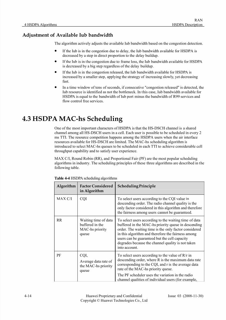
MAX C/I, Round Robin (RR), and Proportional Fair (PF) are the most popular schedulingalgorithms in industry. The scheduling principles of these three algorithms are described in the
following table.
Table 4-4 HSDPA scheduling algorithms
Algorithm Factor Consideredin Algorithm
Scheduling Principle
MAX C/I CQI To select users according to the CQI value in
descending order. The radio channel quality is the
only factor considered in this algorithm and thereforethe fairness among users cannot be guaranteed.
RR Waiting time of data
buffered in theMAC-hs priorityqueue
To select users according to the waiting time of data
buffered in the MAC-hs priority queue in descendingorder. The waiting time is the only factor consideredin this algorithm and therefore the fairness among
users can be guaranteed but the cell capacitydegrades because the channel quality is not takeninto account.
PF CQI, To select users according to the value of R/r indescending order, where R is the maximum data rate
corresponding to the CQI, and r is the average datarate of the MAC-hs priority queue.
Average data rate of
the MAC-hs priorityqueue
The PF scheduler uses the variation in the radio
channel qualities of individual users (for example,
7/27/2019 HSDPA Description(2008!11!30)
http://slidepdf.com/reader/full/hsdpa-description20081130 35/55
RAN
HSDPA Description 4 HSDPA Algorithms
Issue 03 (2008-11-30) Huawei Proprietary and Confidential
Copyright © Huawei Technologies Co., Ltd
4-15
Algorithm Factor Consideredin Algorithm
Scheduling Principle
multi-user diversity) and provides the user with an
average throughput proportional to its average CQI.
This algorithm is a tradeoff between cell capacityand fairness among users.
When the HS-DSCH carries only the BE service, the PF scheduling algorithm can make a
tradeoff between user equity and cell throughput. When the HS-DSCH carries more types of services, such as VoIP, streaming, SRB, and IMS, the HSDPA scheduling algorithm needs to
guarantee the QoS. The reason is that such services have high requirements for delay or GBR.Based on the PF, the EPF algorithm is designed to guarantee the QoS of the followingservices:
z SRB and IMS have high requirements for service connection delay and handover delay.
In addition, the average traffic volume and the consumption of the Uu interface are low.Therefore, the algorithm always selects the MAC-hs queues of SRB and IMS first.
z The VoIP service is highly delay sensitive. The maximum delay of MAC-d PDUs in a
queue is specified by the discard timer of the MAC-hs queue. The scheduler needs tosend out the MAC-d PDUs before the discard timer expires. The discard timer is usually
shorter than 100 ms. Therefore, the scheduler has little chance of considering the channelquality. The scheduler always selects VoIP services after scheduling SRB and IMS
services. Among MAC-hs queues of VoIP, the selection is based on both delay andchannel quality.
z The streaming service is usually the CBR (Constant Bit Rate) streaming service. If the
rate of this service is not lower than the GBR, the user can obtain good experience.Therefore, the scheduler needs to guarantee the GBR. When the average rate of thestreaming service is lower than the GBR, the queues of the streaming service are selected
first after SRB, IMS, and VoIP. Among the MAC-hs queues of the streaming service, theselection is based on PF.
z The BE service is allocated with the remaining resource after the resource requirements
of the SRB, IMS, VoIP, and streaming services are met. Among the MAC-hs queues of the BE service, the selection is based on PF. In addition, the resource allocation complies
with the following rules. Firstly, the GBR should be guaranteed first. Secondly, thealgorithm considers the requirement for user differentiation. For all the users in the cell,
the scheduler intends to allocate the radio resource in proportion to their Weight of SPI,which is based on user priorities, eg. gold, silver and copper. For example, assuming that
radio resource is the bottleneck, gold , silver and copper users of same channel qualityare using FTP service simultaneously, then the Uu throughputs of gold, silver and copper
users are in proportion to the ratio of their SPI weights. For another example, assumingthat the silver user is using HTTP service, the gold and copper user are using FTP service,
and the silver user are reading the HTTP page, then the gold and copper users share the
radio resource, and the Uu throughput of the gold and copper users are in proportion tothe ratio of their SPI weight.
In a network, some UEs may be in a poor radio environment. More cell resources are used toensure the GBR of these UEs, and consequently, quite few cell resources are available for
other UEs. To avoid this problem, the resource limiting function is used. This function can beenabled through the parameter Resource Limiting Switch, which can be set on the NodeB
LMT.
If Scheduling Method is set to EPF and Resource Limiting Switch is set to OPEN, theresource limiting function is enabled.
7/27/2019 HSDPA Description(2008!11!30)
http://slidepdf.com/reader/full/hsdpa-description20081130 36/55
4 HSDPA Algorithms
RAN
HSDPA Description
4-16 Huawei Proprietary and Confidential
Copyright © Huawei Technologies Co., Ltd
Issue 03 (2008-11-30)
The parameter that specifies the switch for resource limiting is shown as follows:
Resource limiting ratio is fixed according to GBR. The maximum ratio of the resource that
can be used by GBR users is shown as follows:
GBR (bit/s) Maximum Ratio
8k 10%
16k 10%
32k 15%
64k 15%
128k 20%
256k 25%
384k 30%
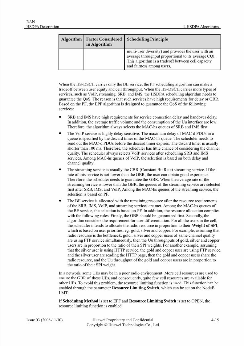
After scheduling, HSDPA users will be allocated to different time and code. The followingfigure shows the time division and code division over the air interface for HSDPA users in one
cell.
Figure 4-9 HSDPA scheduling based on time division and code division
Setting the Scheduling Algorithm
The scheduling algorithm can be set through Scheduling Method on NodeB LMT. Thesettings are described as follows:
z PF: The service types of queues are not considered. All the queues in a cell aresequenced according to the PF values.
z RR: The service types of queues are not considered. All the queues in a cell aresequenced according to the RR values.
z MAXCI: The service types of queues are not considered. All the queues in a cell aresequenced according to the MAXCI values.
z EPF: The types of queues are considered. For each type of service, you can set a
scheduling algorithm and a scheduling priority through the EPF Schedule Algorithm
Switch parameter on NodeB LMT. The setting should be based on the mapping between
service types and SPIs. For details of the EPF based on SPI, refer to Table 4-3.

7/27/2019 HSDPA Description(2008!11!30)
http://slidepdf.com/reader/full/hsdpa-description20081130 37/55
RAN
HSDPA Description 4 HSDPA Algorithms
Issue 03 (2008-11-30) Huawei Proprietary and Confidential
Copyright © Huawei Technologies Co., Ltd
4-17
− DS_PQ_SCHEDULE: SRB/IMS scheduling policy. The SRB and IMS queues arescheduled before the VoIP, streaming and BE queues. DS means delay sensitive. PQmeans priority queue.
− DS_URGENT_SCHEDULE: VoIP scheduling policy. The VoIP queues are scheduled
before the streaming and BE queues but after the SRB and IMS queues.− TS_SCHEDULE: streaming/BE scheduling policy. The streaming and BE queues are
scheduled after the SRB, IMS, and VoIP queues. Among the streaming and BEqueues, the resources for GBR are allocated first. The remaining resources are
allocated as required by golden, silver, and copper users. TS means throughputsensitive.
4.4 HSDPA TFRC Selection
4.4.1 Overview of TFRC Selection
TFRC selection determines the transport block size, modulation type, HS-PDSCH codes, and
HS-PDSCH transmission power. The UEs estimate and send CQI to the UTRAN to aid theTFRC selection.
The HSDPA resources over the Uu interface are allocated on a per cell basis. The scheduling
algorithm arranges the MAC-hs queues in a cell in a certain order and then allocates resourcesto users in descending order of scheduling priority. The resource allocation takes the total
available Uu resources, channel quality, and amount of data cached in the MAC-hs queue intoconsideration, with the output of the Transport Block Size (TBS), modulation mode, number
of HS-PDSCH codes occupied, and allocated HS-PDSCH power of the HS-DSCH user withinthe current TTI.
The Transport Format Resource Combination (TFRC) selection is based on CQI-Max TBSmapping table, as shown in the following figure, which reflects the application of AdaptiveModulation and Coding (AMC) in HSDPA. For AMC, the UE measures the downlink channel
quality and provides CQI feedback in the uplink, and the network adjusts the modulation andcoding scheme for the UE based on the CQI in an adaptive manner. For example, when thechannel quality is good, high order modulation can be applied to achieve higher throughput.

7/27/2019 HSDPA Description(2008!11!30)
http://slidepdf.com/reader/full/hsdpa-description20081130 38/55
4 HSDPA Algorithms
RAN
HSDPA Description
4-18 Huawei Proprietary and Confidential
Copyright © Huawei Technologies Co., Ltd
Issue 03 (2008-11-30)
Figure 4-10 TFRC selection process
The figure shows the process of TFRC selection.
1. Assuming that all the available Uu resources within the current Transmission Time
Interval (TTI) are allocated to the UE, calculate the maximum Transport Block Size(TBSmax) based on the CQI from the UE and the reception capability of the UE. The
calculation of TBSmax within the current TTI takes the following factors intoconsideration:
z Available power of the HS-PDSCH
The HSDPA power allocated to the scheduled users within the current TTI and theHS-SCCH power allocated to the UE within the current TTI are excluded. In addition,
the total transmit power for one UE within a TTI cannot exceed the value of the MAX
POWER PER HS-USER parameter.
z Available codes of the HS-PDSCH
z CQI from the UE
For the purpose of CQI reporting, the UE assumes the total received HS-PDSCH power
as follows.
P HS-PDSCH = PCPICH + Γ + Δ
where,
− PCPICH is the power of the CPICH.

7/27/2019 HSDPA Description(2008!11!30)
http://slidepdf.com/reader/full/hsdpa-description20081130 39/55
RAN
HSDPA Description 4 HSDPA Algorithms
Issue 03 (2008-11-30) Huawei Proprietary and Confidential
Copyright © Huawei Technologies Co., Ltd
4-19
− Δ is the reference power adjustment. For detailed information, see 3GPP TS 25.214.
− Γ = Max(-6, Min(13, P CellMAX - PCPICH - MPOconstant))
− PCell-MAX - PCPICH = maximum transmit power of the cell - CPICH transmit power
− MPOconstant represents HS-PDSCH MPO Constant and can be set on the RNC LMT.
z UE capability
It denotes that the maximum number of HS-PDSCH code that the UE can use, the
maximum size of the transport block that the UE can receive, and whether the UEsupports 16QAM.
2. If there is sufficient amount of data cached in the MAC-hs queue (TBSmax < Queue
length), the data is scheduled for the UE as much as possible in the maximum format of TFRC, that is, TBS = TBSmax.
3. If there is insufficient amount of data cached in the queue (TBSmax > Queue length), theUu resources necessary for the UE are allocated on the basis of the amount of data in thequeue.
Select the TFRC (power, code, and modulation mode) by searching the CQI-Max TBSmapping table and taking the amount of data cached in the queue into consideration. The
search is based on the priority defined by the Resource Allocate Method parameter, thatis, code preferable or power preferable.
Outdoor cells usually have sufficient code resources but limited power resources.Therefore, for outdoor cells, codes take precedence over power during TFRC selection,
so as to achieve resource efficiency in both code and power and to improve the cellthroughput. For indoor cells, the priorities of codes and power are just the opposite, that
is, power usually takes precedence over codes.
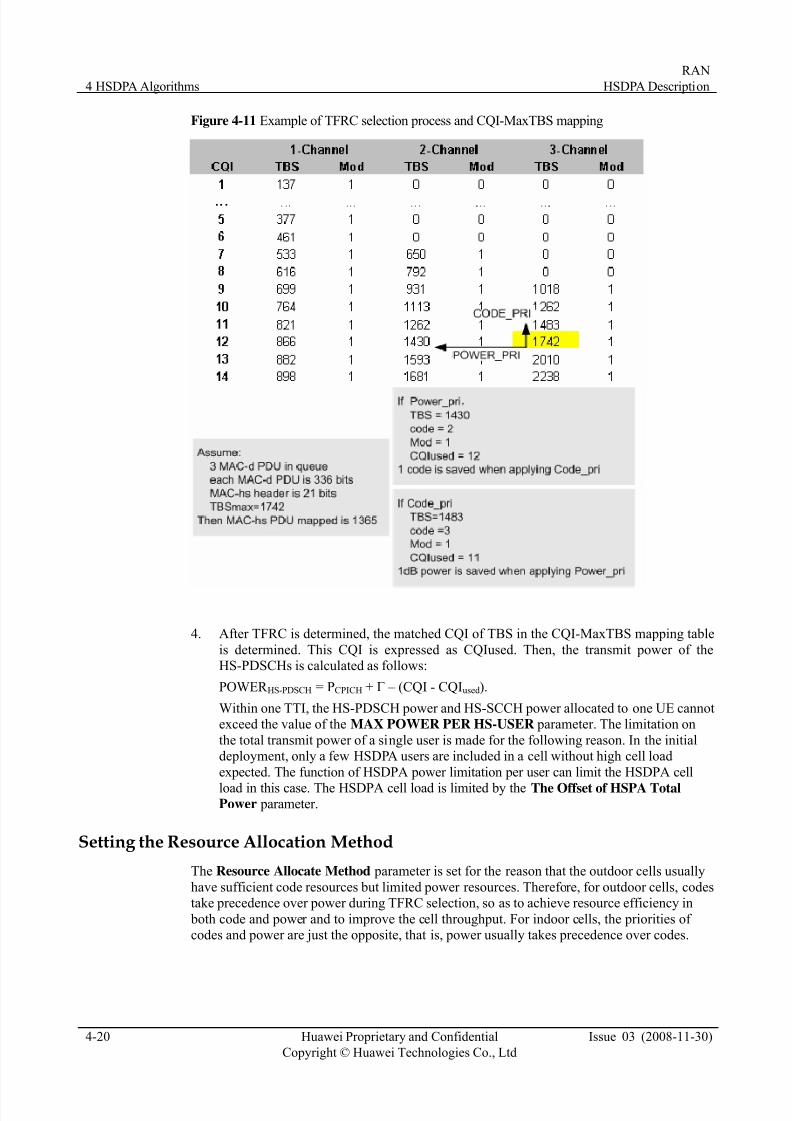
The following figure shows an example of TBSmax searching.
7/27/2019 HSDPA Description(2008!11!30)
http://slidepdf.com/reader/full/hsdpa-description20081130 40/55
4 HSDPA Algorithms
RAN
HSDPA Description
4-20 Huawei Proprietary and Confidential
Copyright © Huawei Technologies Co., Ltd
Issue 03 (2008-11-30)
Figure 4-11 Example of TFRC selection process and CQI-MaxTBS mapping
4. After TFRC is determined, the matched CQI of TBS in the CQI-MaxTBS mapping table
is determined. This CQI is expressed as CQIused. Then, the transmit power of theHS-PDSCHs is calculated as follows:
POWER HS-PDSCH = PCPICH + Γ – (CQI - CQIused).
Within one TTI, the HS-PDSCH power and HS-SCCH power allocated to one UE cannotexceed the value of the MAX POWER PER HS-USER parameter. The limitation on
the total transmit power of a single user is made for the following reason. In the initialdeployment, only a few HSDPA users are included in a cell without high cell load
expected. The function of HSDPA power limitation per user can limit the HSDPA cell
load in this case. The HSDPA cell load is limited by the The Offset of HSPA TotalPower parameter.
Setting the Resource Allocation Method
The Resource Allocate Method parameter is set for the reason that the outdoor cells usually
have sufficient code resources but limited power resources. Therefore, for outdoor cells, codestake precedence over power during TFRC selection, so as to achieve resource efficiency in
both code and power and to improve the cell throughput. For indoor cells, the priorities of codes and power are just the opposite, that is, power usually takes precedence over codes.

7/27/2019 HSDPA Description(2008!11!30)
http://slidepdf.com/reader/full/hsdpa-description20081130 41/55
RAN
HSDPA Description 4 HSDPA Algorithms
Issue 03 (2008-11-30) Huawei Proprietary and Confidential
Copyright © Huawei Technologies Co., Ltd
4-21
Setting MPO
If the value of HS-PDSCH MPO Constant is set properly, the probability of CQI being
equal to 0 or 30 is very low, for example, 1% or lower. Otherwise, the parameter value should
be adjusted. This parameter is set for the purpose that the CQI reported is within the range of
1 to 30.
4.5 HSDPA Power Resource Managementz Overview of Power Resource Management
z Dynamic Power Resource Allocation
4.5.1 Overview of Power Resource Management
The maximum cell transmit power is a constant. The DL power consists of the following
parts:
z Power of DL HSPA physical channels, including the HS-PDSCH, HS-SCCH, E-AGCH,
E-RGCH, and E-HICH
The maximum available power can be set on the RNC LMT through parameter The
Offset of HSPA Total Power.
z Power of common physical channels
This type of power is reserved.
z Power of the DPCH
HSDPA power resource management addresses the following issues:
z The dynamic power allocation between HS-DSCH and R99 channels when HS-DSCHand R99 channels are on the same carrier frequencies.
z HS-DSCH power control: See HS-SCCH power control and HS-DPCCH power controlin Power Control.
z HS-PDSCH power allocation: See 4.4.1 Overview of TFRC Selection.
4.5.2 Dynamic Power Resource Allocation
The cell power resources are allocated dynamically between the DPCH and the DL HSPA
physical channels, but the power resources are reserved for the common physical channels.
After power resources are allocated to the DPCH, E-HICH, E-AGCH, and E-RGCH, the
remaining resources are allocated to the HS-SCCH and HS-PDSCH. The power allocated toHSPA cannot exceed The Offset of HSPA Total Power.
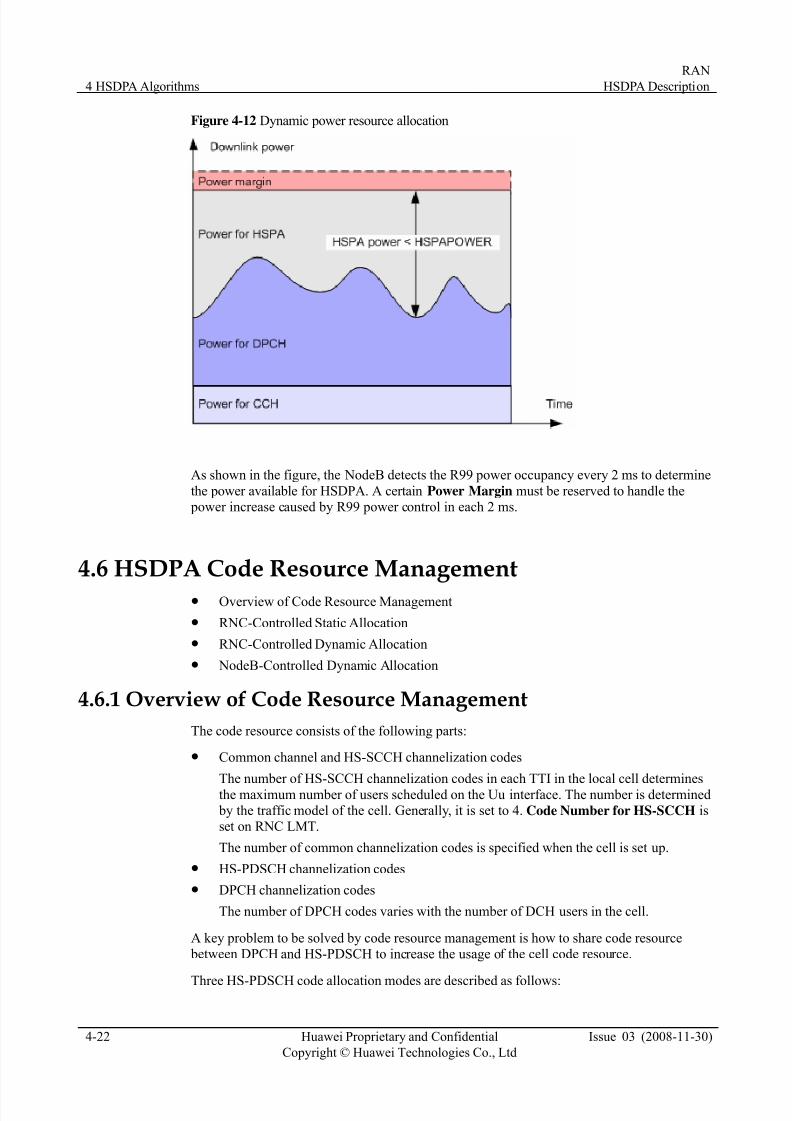
7/27/2019 HSDPA Description(2008!11!30)
http://slidepdf.com/reader/full/hsdpa-description20081130 42/55
4 HSDPA Algorithms
RAN
HSDPA Description
4-22 Huawei Proprietary and Confidential
Copyright © Huawei Technologies Co., Ltd
Issue 03 (2008-11-30)
Figure 4-12 Dynamic power resource allocation
As shown in the figure, the NodeB detects the R99 power occupancy every 2 ms to determine
the power available for HSDPA. A certain Power Margin must be reserved to handle the power increase caused by R99 power control in each 2 ms.
4.6 HSDPA Code Resource Managementz Overview of Code Resource Management
z RNC-Controlled Static Allocation
z RNC-Controlled Dynamic Allocation
z NodeB-Controlled Dynamic Allocation
4.6.1 Overview of Code Resource Management
The code resource consists of the following parts:
z Common channel and HS-SCCH channelization codes
The number of HS-SCCH channelization codes in each TTI in the local cell determinesthe maximum number of users scheduled on the Uu interface. The number is determined by the traffic model of the cell. Generally, it is set to 4. Code Number for HS-SCCH isset on RNC LMT.
The number of common channelization codes is specified when the cell is set up.
z HS-PDSCH channelization codes
z DPCH channelization codes
The number of DPCH codes varies with the number of DCH users in the cell.
A key problem to be solved by code resource management is how to share code resource between DPCH and HS-PDSCH to increase the usage of the cell code resource.
Three HS-PDSCH code allocation modes are described as follows:

7/27/2019 HSDPA Description(2008!11!30)
http://slidepdf.com/reader/full/hsdpa-description20081130 43/55
RAN
HSDPA Description 4 HSDPA Algorithms
Issue 03 (2008-11-30) Huawei Proprietary and Confidential
Copyright © Huawei Technologies Co., Ltd
4-23
z RNC-controlled static code allocation
In the static code allocation, the HS-PDSCH codes are configured on the RNC LMT, and
the allocated codes recorded on the RNC can be modified only through the Allocate
Code Mode parameter.
z RNC-controlled dynamic code allocationIt is is set through the Allocate Code Mode parameter on RNC LMT.
z NodeB-controlled dynamic code allocation
It is set through the Dynamic Code Switch parameter.
In the RNC-controlled and NodeB-controlled dynamic code allocation, the HS-PDSCH code
range is configured on the LMT. The UTRAN can automatically adjust the number of HS-PDSCH codes in real time based on the current cell codes used by R99 channels to
maximize the usage.
The HS-PDSCH codes received by the UE in a TTI must be continuous. Therefore, the
algorithm should try to reserve codes adjacent to the reserved HS-PDSCH codes during code
allocation to the DL dedicated channels of the cell. Thus, the HS-PDSCH can have as manyavailable codes as possible. When the state of the code resource used by R99 channels
changed, the algorithm rearranges the allocated R99 codes so that more continuous SF16codes are available for HSDPA.
NodeB-controlled dynamic allocation allows the NodeB to use the HS-PDSCH codes
allocated by the RNC and also can dynamically allocate the idle codes of the current cell tothe HS-PDSCH channel. It is more flexible to allocate the code for HS-PDSCH through the
NodeB-controlled dynamic allocation than the RNC-controlled dynamic allocation. NodeB-controlled dynamic allocation can save the signaling traffic resource for code
reconfiguration on the Iub interface, compared to the RNC-controlled dynamic allocation.
The following HS-PDSCH code allocation scheme is preferred:
z The RNC uses the static code allocation. The fixed number of reserved HS-PDSCH
codes is specified by Code Number for HS-PDSCH. The NodeB uses the dynamic codeallocation so that the HS-PDSCH codes can be increased.
z If the NodeB does not support the dynamic code allocation, you can enable the dynamiccode allocation on the RNC side through the parameters Code Max Number for
HS-PDSCH and Code Min Number for HS-PDSCH.
The HS-PDSCH code allocation mode can be set through Allocate Code Mode.
4.6.2 RNC-Controlled Static Code Allocation
In static allocation, the RNC reserves codes for the HS-PDSCH. The DPCH, HS-SCCH, and
common channels use the remaining codes.
Figure 4-13 Static allocation
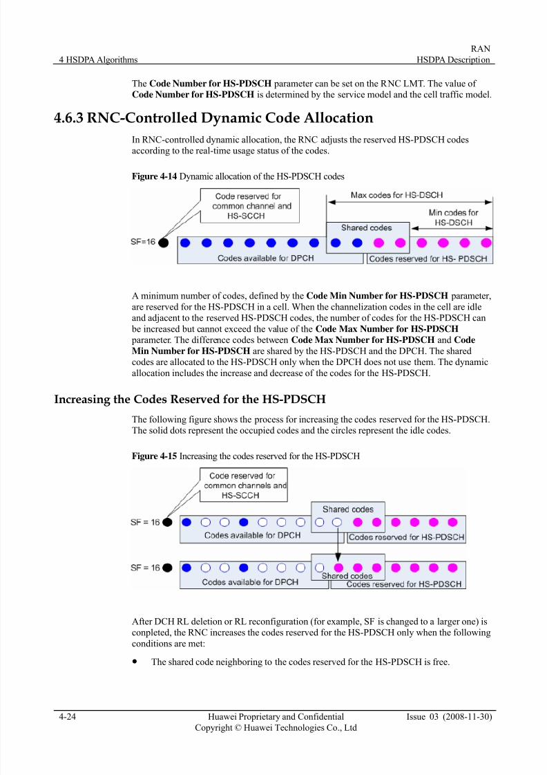
7/27/2019 HSDPA Description(2008!11!30)
http://slidepdf.com/reader/full/hsdpa-description20081130 44/55
4 HSDPA Algorithms
RAN
HSDPA Description
4-24 Huawei Proprietary and Confidential
Copyright © Huawei Technologies Co., Ltd
Issue 03 (2008-11-30)
The Code Number for HS-PDSCH parameter can be set on the RNC LMT. The value of Code Number for HS-PDSCH is determined by the service model and the cell traffic model.
4.6.3 RNC-Controlled Dynamic Code Allocation
In RNC-controlled dynamic allocation, the RNC adjusts the reserved HS-PDSCH codesaccording to the real-time usage status of the codes.
Figure 4-14 Dynamic allocation of the HS-PDSCH codes
A minimum number of codes, defined by the Code Min Number for HS-PDSCH parameter,
are reserved for the HS-PDSCH in a cell. When the channelization codes in the cell are idleand adjacent to the reserved HS-PDSCH codes, the number of codes for the HS-PDSCH can
be increased but cannot exceed the value of the Code Max Number for HS-PDSCH parameter. The difference codes between Code Max Number for HS-PDSCH and Code
Min Number for HS-PDSCH are shared by the HS-PDSCH and the DPCH. The sharedcodes are allocated to the HS-PDSCH only when the DPCH does not use them. The dynamic
allocation includes the increase and decrease of the codes for the HS-PDSCH.
Increasing the Codes Reserved for the HS-PDSCH
The following figure shows the process for increasing the codes reserved for the HS-PDSCH.The solid dots represent the occupied codes and the circles represent the idle codes.
Figure 4-15 Increasing the codes reserved for the HS-PDSCH
After DCH RL deletion or RL reconfiguration (for example, SF is changed to a larger one) isconpleted, the RNC increases the codes reserved for the HS-PDSCH only when the following
conditions are met:
z The shared code neighboring to the codes reserved for the HS-PDSCH is free.

7/27/2019 HSDPA Description(2008!11!30)
http://slidepdf.com/reader/full/hsdpa-description20081130 45/55
RAN
HSDPA Description 4 HSDPA Algorithms
Issue 03 (2008-11-30) Huawei Proprietary and Confidential
Copyright © Huawei Technologies Co., Ltd
4-25
z After increasing the codes for the HS-DSCH, the SF of the remaining codes should beequal to or smaller than the value of Cell LDR SF reserved threshold.
Cell LDR SF reserved threshold is used to reserve code resources for new admission and
avoid code resource congestion. For details of Cell LDR SF reserved threshold, refer to
Basic Congestion Triggering in Load Control.
Reducing the Codes Reserved for the HS-PDSCH
The following figure shows the process of reducing the codes reserved for the HS-PDSCH.
The solid dots represent the occupied codes and the circles represent the idle codes.
Figure 4-16 Reducing the codes reserved for the HS-PDSCH
After DCH RL setup, RL addition, or RL reconfiguration (for example, SF is changed to asmaller one) is completed,, the RNC will reallocate one of the shared codes reserved for the
HS-PDSCH to the DPCH. After reallocating, the minimum SF of free codes should be lower than Cell LDR SF reserved threshold. The re-allocated code number should be the smallestone.
4.6.4 NodeB-Controlled Dynamic Code Allocation
NodeB-controlled dynamic allocation allows the NodeB to use the HS-PDSCH codes
allocated by the RNC. The NodeB can dynamically allocate the idle codes of the current cellto the HS-PDSCH.
Figure 4-17 NodeB controlled dynamic allocation of the HS-PDSCH codes
The NodeB detects the SF16 codes that are not for the HS-PDSCH every 2 ms. If the codes or sub-codes are allocated by the RNC to the DCH or common channels, they are regarded as
occupied. Otherwise, they are regarded as unoccupied. Therefore, the HS-PDSCH codesavailable for the HS-PDSCH include the codes allocated by the RNC and those unoccupied
consecutive SF16 codes that are adjacent to the reserved HS-DSCH codes.

7/27/2019 HSDPA Description(2008!11!30)
http://slidepdf.com/reader/full/hsdpa-description20081130 46/55
4 HSDPA Algorithms
RAN
HSDPA Description
4-26 Huawei Proprietary and Confidential
Copyright © Huawei Technologies Co., Ltd
Issue 03 (2008-11-30)
For example, in a cell HS-PDSCH, the RNC allocates SF16 codes numbered 11 to 15 toHS-PDSCH, SF16 codes numbered 0 to 5 to the DCH and common channels. Then, in thisTTI, the HS-PDSCH can use SF16 codes numbered 6 to 15.
If the DCH codes allocated by the RNC are temporarily occupied by the HS-PDSCH before
the setup of a radio link, the NBAP message is sent to the RNC, indicating that the radio link is set up successfully. Then, the DCH occupies the codes. The HS-PDSCH cannot use these
codes until they are released by the DCH.
4.7 Other HSDPA Related Algorithms
4.7.1 Mapping of Service to HSDPA
SRB over HSDPA
This feature provides a higher signaling rate and reduces the call process delay. Comparedwith the scenario where the SRB is carried on the DCH, code resources are saved and cell
load is reduced when the SRB is carried on HSDPA.
The signaling over SRB is delay-sensitive and irregular. In some cases, the code may be
limited prior to power and the cell capacity is affected. Thus, it is more appropriate to set upSRB over HSDPA rather than the DCH. Moreover, while the SRB is over HSDPA, the
F-DPCH multiplexed by users is introduced, and thus saving code resources.
SRB over HSDPA can be applied during the RRC connection setup procedure or other procedures such as mobility management.
If the SRB is set up over the DCH, it can be reconfigured to the mapping on HSDPA in some
cases, for example, if the target cell of handover supports HSDPA while the source cell doesnot. Inversely, the SRB mapping on HSDPA can also be reconfigured to the mapping on DCH
if the target cell of handover does not support HSDPA.
SRB over HSDPA is configurable. For details, refer to Radio Bearers Description.
VoIP over HSPA
In the fixed network, Voice over IP (VoIP) has turned out to be an attractive and cost-effective
solution to support PS conversational services. The rapid growth of VoIP users urges thecellular operator to introduce this feature to make their network more profitable. Moreover,
from the evolution point view, it is also helpful to converge the operator’s network into one
all-IP network and decrease the total operational cost accordingly.
In WCDMA system, on the one hand, VoIP can provide lower cost voice service compared to
the traditional CS voice, and on the other hand, such service can make it simpler to supportrich services like real-time video sharing or messenger. The reason is that they are all carried
on the PS domain and the end user will also benefit from it.
VoIP service can be carried on DCH or HSPA. When it is set up on the DCH, the capacity isnot competitive due to more resource consumption. Therefore, VoIP over HSPA is a better
solution. And Robust Header Compression (RoHC) should also be supported to improve theoverhead efficiency. The following features are to provide VoIP over HSPA solution:
z RAB Mapping, refer to Radio Bearers Description.
7/27/2019 HSDPA Description(2008!11!30)
http://slidepdf.com/reader/full/hsdpa-description20081130 47/55
RAN
HSDPA Description 4 HSDPA Algorithms
Issue 03 (2008-11-30) Huawei Proprietary and Confidential
Copyright © Huawei Technologies Co., Ltd
4-27
z Optimized scheduling for VoIP over HSPA, refer to HSDPA Description and HSUPA Description.
z RoHC, refer to PDCP Header Compression Description.
IMS Signaling over HSPAThe IP Multimedia Subsystem (IMS) is an open and standardized architectural framework for
delivering Internet Protocol (IP) multimedia to mobile users. With this feature, operators provide network-controlled multimedia services by combining voice and data in a single
packet switched network.
IMS Signaling over HSPA improves the utilization of code resource and transmission resource,compared with those carried on the DCH.
IMS uses Session Initiation Protocol (SIP) as the key control protocol, and implements
service management in the UTRAN. Such SIP signaling will be indicated by the CN in theRAB Assignment Request message. The RAB should be an interactive QoS class service.
Before RAN10.0, such IMS signaling service can only be carried on the DCH. In RAN10.0, itis considered to carry the service on HSPA, which brings better performance for IMS service.
The type of channels carrying IMS signaling is configurable separately on the downlink and
uplink at cell level. That is, when HSPA is chosen as the bearer with high priority, IMSsignaling will be set up on it as much as possible. If the setup is not successful, for example,
due to admission control, a periodical timer will be started to trigger the reconfiguration of theHSPA procedure.
The IMS signaling can be mapped on the DCH, HS-DSCH, or E-DCH. For details, refer to
Radio Bearers Description.
4.7.2 HS-DPCCH Preamble
The High Speed Dedicated Physical Control Channel (HS-DPCCH) carries uplink feedback signaling related to downlink HS-DSCH transmission. The HS-DSCH-related feedback
signaling consists of Hybrid-ARQ Acknowledgement (HARQ-ACK) and Channel-QualityIndication (CQI).
If UE detects the HS-SCCH control message, it will reply with an ACK or NACK message based on the result of the decoding and inform the sender of the result to further requestretransmissions.
If the UE has not detected the HS-SCCH control message, it will reply with a DTX message.To reduce the probability that the NodeB erroneously decodes this DTX as ACK, theACK/NACK requires high transmit power.
The proposed enhancement is to send special Preamble and Postamble sub-frames in theuplink HS-DPCCH before and after an ACK/NACK sub-frame. This method reduces the probability of a DTX->ACK error in the NodeB, because the NodeB has to decode at least
two successive timeslots erroneously before the earlier mentioned scenario could take place.
Due to the prior preamble information detection, the same performance of the HARQ-ACK field detection can be kept with lower power.

7/27/2019 HSDPA Description(2008!11!30)
http://slidepdf.com/reader/full/hsdpa-description20081130 48/55
4 HSDPA Algorithms
RAN
HSDPA Description
4-28 Huawei Proprietary and Confidential
Copyright © Huawei Technologies Co., Ltd
Issue 03 (2008-11-30)
Figure 4-18 HS-DPCCH preamble and postamble
4.7.3 HSDPA over Iur
HSDPA over Iur is the scenario where the HSDPA serving cell is carried at the DRNC. The
feature includes HSDPA service management over Iur, HSDPA mobility management over Iur,and so on.
HSDPA service management over IurHSDPA service management over Iur refers to HSDPA service setup, modification, release,
and state transition.
When the UE is in the CELL_DCH state and the DRNC cell is in the active set or the UE is in
the CELL_FACH state and camps in a DRNC cell, the HSDPA service can be setup, modified,and released over Iur.
The service over Iur can be reconfigured between HSDPA and R99 with UE state transition between CELL_DCH and CELL_FACH.
HSDPA mobility management over Iur
HSDPA mobility management over Iur includes hard handover, cell update (caused by radio
link failure), and serving cell change.
In this example (from TS25.931) the source Node B and the target Node B are controlled by
two different DRNCs, referred to as source DRNC and target DRNC, respectively. In this casethe HS-DSCH mobility procedure is performed in a single step.

7/27/2019 HSDPA Description(2008!11!30)
http://slidepdf.com/reader/full/hsdpa-description20081130 49/55
RAN
HSDPA Description 4 HSDPA Algorithms
Issue 03 (2008-11-30) Huawei Proprietary and Confidential
Copyright © Huawei Technologies Co., Ltd
4-29
Figure 4-19 Inter-Node B (inter DRNC) synchronized serving HS-DSCH cell change at hardhandover
HSDPA static relocation
If the HSDPA service is over Iur and the radio links are provided only by the target RNC, the
static relocation can be triggered.
4.7.4 HSDPA Cell Load Control
The UE can access an HSDPA cell only after it passes all of the following admission
decisions:
z Admission decision based on power resources
z Admission decision based on Iub resources
z Admission decision based on UE quantity
For detailed information, see Load Control.
4.7.5 HSDPA Mobility ManagementHSDPA Mobility Management is applied in the mobility scenarios in which the HSDPA
serving cell is involved.
For details, refer to Intra-Frequency Handover, Inter-Frequency Handover and Inter-RATHandover Description.
4.7.6 HSDPA Channel Switching
HSDPA channel switching consists of channel switching between HS-DSCH and FACH and
channel switching between HS-DSCH and DCH.
HSDPA channel switching refers to the following aspects:

7/27/2019 HSDPA Description(2008!11!30)
http://slidepdf.com/reader/full/hsdpa-description20081130 50/55
4 HSDPA Algorithms
RAN
HSDPA Description
4-30 Huawei Proprietary and Confidential
Copyright © Huawei Technologies Co., Ltd
Issue 03 (2008-11-30)
z UE State Transition
z Channel Switching Between HS-DSCH and FACH
z Channel Switching Between HS-DSCH and DCH
UE State Transition
After the HSDPA technology is introduced, a UE has a new RRC state, CELL_DCH (with
HS-DSCH). The following figure shows the UE state transition.
Figure 4-20 UE state transition
The following table lists the UE state transition and channel switching.
Table 4-5 UE state transition and channel switching
UE State Transition Channel Switching
CELL_DCH (with HS-DSCH) <-> CELL_DCH HS-DSCH <-> DCH
CELL_DCH (with HS-DSCH) <-> CELL_FACH HS-DSCH <-> FACH
Channel Switching Between HS-DSCH and FACH
To reduce the DPCH occupancy by the HSDPA UE, the RAN switches the transport channel
from HS-DSCH to FACH. For details, refer to UE State Transition Algorithm in Rate Control
Description.
Channel Switching Between HS-DSCH and DCH
Channel switching from DCH to HS-DSCH can be triggered by mobility management, traffic
volume, or timer. In comparison, channel switching from HS-DSCH to DCH can only betriggered by mobility management.
z Channel switching triggered by mobility management
z For detailed information, see Intra-Frequency Handover and Inter-Frequency Handover.
z Channel switching triggered by H Retry Timer Length. For detailed information, seeMapping of Signaling and Traffic onto Transport Channels.
z Channel switching triggered by traffic volume

7/27/2019 HSDPA Description(2008!11!30)
http://slidepdf.com/reader/full/hsdpa-description20081130 51/55
RAN
HSDPA Description 4 HSDPA Algorithms
Issue 03 (2008-11-30) Huawei Proprietary and Confidential
Copyright © Huawei Technologies Co., Ltd
4-31
z The UE is rejected by the admission control algorithm when it attempts to access anHSDPA cell. If the activity of the UE that performs data services increases and the RNCreceives an event 4A report, the RAN tries to hand over the UE from the DCH to theHS-DSCH.
Channel switching from DCH or FACH to HS-DSCH needs to implement the process of HSDPA directed retry.
4.7.7 HSDPA TX Diversity
The TX diversity mode of the HS-PDSCH can be set through the Hspdsch priority Tx
diversity mode parameter on the RNC LMT.

7/27/2019 HSDPA Description(2008!11!30)
http://slidepdf.com/reader/full/hsdpa-description20081130 52/55
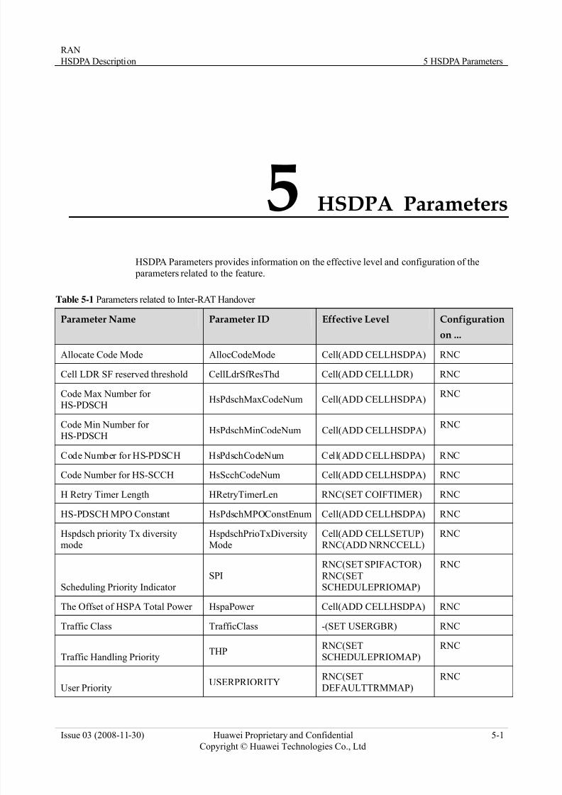
7/27/2019 HSDPA Description(2008!11!30)
http://slidepdf.com/reader/full/hsdpa-description20081130 53/55
RAN
HSDPA Description 5 HSDPA Parameters
Issue 03 (2008-11-30) Huawei Proprietary and Confidential
Copyright © Huawei Technologies Co., Ltd
5-1
5 HSDPA Parameters
HSDPA Parameters provides information on the effective level and configuration of the
arameters related
Table 5-1 Parameters related to Inter-RAT Handover
p to the feature.
Parameter ID Effective Level Configuration
on ... Parameter Name
Allocate Code Mode AllocCodeMode Cell(ADD CELLHSDPA) RNC
Cell LDR SF reserved threshold CellLdrSfResThd Cell(ADD CELLLDR) RNC
Code Max Number for HsPdschMaxCodeNum Cell(ADD CELLHSDPA)
RNCHS-PDSCH
Code Min Number for HS-PDSCH
HsPdschMinCodeNum Cell(ADD CELLHSDPA)RNC
Code Number for HS-PDSCH HsPdschCodeNum Cell(ADD CELLHSDPA) RNC
Code Number for HS-SCCH HsScchCodeNum Cell(ADD CELLHSDPA) RNC
H Retry Timer Length HRetryTimerLen RNC(SET COIFTIMER) RNC
HS-PDSCH MPO Constant HsPdschMPOConstEnum Cell(ADD CELLHSDPA) RNC
Hspdsch priority Tx diversity schPrioTxDiversityMode
ELLSETUP) RNCHspd Cell(ADD CRNC(ADD NRNCCELL)mode
Scheduling Priority Indicator AP)
SPIRNC(SET SPIFACTOR)
RNC(SETSCHEDULEPRIOM
RNC
The Offset of HSPA Total Power wer HspaPo Cell(ADD CELLHSDPA) RNC
Traffic Class TrafficClass RGBR)-(SET USE RNC
Traffic Handling PriorityTHP
EPRIOMAP)
RNCRNC(SET
SCHEDUL
User Priority USERPRIORITY
DEFAULTTRMMAP)
RNC(SET RNC
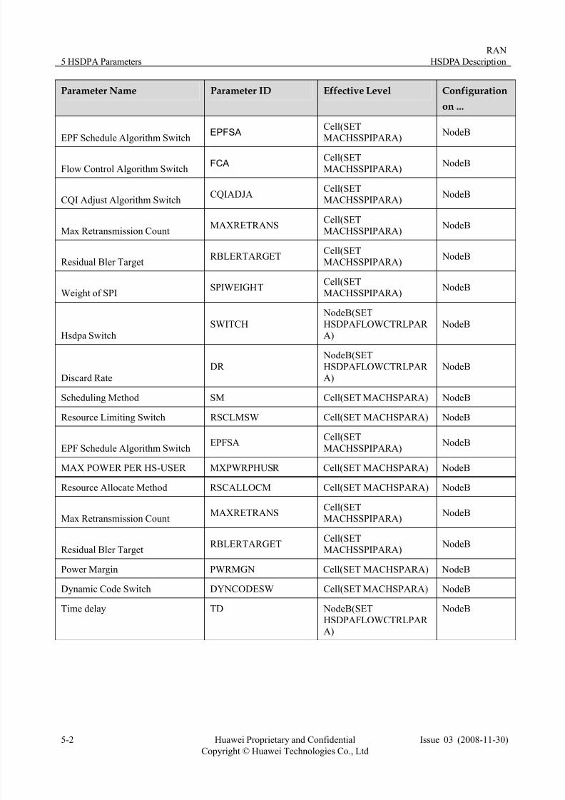
7/27/2019 HSDPA Description(2008!11!30)
http://slidepdf.com/reader/full/hsdpa-description20081130 54/55
5 HSDPA Parameters
RAN
HSDPA Description
5-2 Huawei Proprietary and Confidential
Copyright © Huawei Technologies Co., Ltd
Issue 03 (2008-11-30)
Effective Level Configuration
on ... Parameter Name Parameter ID
EPFSACell(SET
MACHSSPIPARA)
NodeB
EPF Schedule Algorithm Switch
FCACell(SETMACHSSPIPARA)
NodeBFlow Control Algorithm Switch
CQIADJACell(SETMACHSSPIPARA)
NodeBCQI Adjust Algorithm Switch
MAXRETRANSCell(SETMACHSSPIPARA)
NodeBMax Retransmission Count
argetETRBLERTARG
Cell(SETMACHSSPIPARA)
NodeBResidual Bler T
Weight of SPITSPIWEIGH Cell(SET
MACHSSPIPARA) NodeB
Hsdpa SwitchSWITCH NodeB
NodeB(SET
HSDPAFLOWCTRLPAR A)
DR NodeB(SET
HSDPAFLOWCTRLPAR A)
NodeB
Discard Rate
Scheduling Method SM NodeBCell(SET MACHSPARA)
Resource Limiting Switch RSCLMSW RA)Cell(SET MACHSPA NodeB
EPFSACell(SET
MACHSSPIPARA) NodeB
EPF Schedule Algorithm Switch
MAX POWER PER HS-USER MXPWRPHUSR Cell(SET MACHSPARA) NodeB
Resource Allocate Method RSCALLOCM Cell(SET MACHSPARA) NodeB
MAXRETRANSCell(SETMACHSSPIPARA)
NodeBMax Retransmission Count
RBLERTARGETCell(SETMACHSSPIPARA)
NodeBResidual Bler Target
Power Margin PWRMGN Cell(SET MACHSPARA) NodeB
Dynamic Code Switch DYNCODESW NodeBCell(SET MACHSPARA)
Time delay TD
HSDPAFLOWCTRLPAR A)
NodeB NodeB(SET

7/27/2019 HSDPA Description(2008!11!30)
http://slidepdf.com/reader/full/hsdpa-description20081130 55/55
RAN
HSDPA Description 6 HSDPA Reference Documents
6 HSDPA Reference Documents
HSD uments lists the reference documents related to HSDPA.
nd reception (FDD)"
ansport channels onto physical
z 5.213, "Spreading and modulation (FDD)"
z A) - Iub/Iur Protocol
ed Downlink Packet
z 01, "Radio Interface Protocol Architecture"
); Overall
z 3GPP TS 25.430, "UTRAN Iub interface: general aspects and principles"
z 3GPP TS 25.433, "UTRAN Iub interface NBAP signaling"
z 3GPP TS 25.435, "UTRAN Iub interface user plane protocols for CCH data flows"
PA Reference Doc
z 3GPP TS 25.101, "User Equipment (UE) radio transmission a
z 3GPP TS 25.211, "Physical channels and mapping of tr
channels (FDD)"z 3GPP TS 25.212, "Multiplexing and channel coding (FDD)"
3GPP TS 2
z 3GPP TS 25.214, "Physical layer procedures (FDD)"
3GPP TS 25.877, "High Speed Downlink Packet Access (HSDPAspects"
z 3GPP TS 25.858, "Physical layer aspects of UTRA High SpeAccess"
3GPP TS 25.3
z 3GPP TS 25.302, "Services provided by the physical layer"
z 3GPP TS 25.308, "UTRA High Speed Downlink Packet Access (HSPDAdescription"
z 3GPP TS 25.321, "Medium Access Control (MAC) protocol specification"
z 3GPP TS 25.420, "UTRAN Iur interface general aspects and principles"
z 3GPP TS 25.423, "UTRAN Iur interface RNSAP signaling"
z 3GPP TS 25.425, "UTRAN Iur interface user plane protocols for CCH data flows"