HSA 400/402/822 Installation Guide A - Extron...
4
HSA 402 AUDIO PHONE DATA 125 - 50/60 Hz 5A PHONE 125 - 50/60 Hz 5A HSA 402 DATA 1 Hideaway ® Surface Access Products • Installation Guide This guide provides instructions for an experienced installer to install and connect the Extron HSA 400, HSA 402, and HSA 822. The HSA units are lift-up architectural solutions for inconspicuous A/V connectivity access, control, and AC power. Planning Determine the best location for the enclosure. Before making any cuts: c Ensure that the location where the HSA is to be installed is convenient for as many users as possible. c Ensure that the edge on which the HSA opens is oriented correctly. c Ensure that there is ample space under the table for cables. c Ensure that the correct template or dimensions are used. Decide on the method for cutting the hole in the table. c Hand router and template c CNC wood router c Jigsaw and paper template Before starting the installation, check with local and state regulations: c Ensure that the planned installation complies with building and electrical codes. c Ensure that the planned installation complies with the Americans with Disabilities Act or other accessibility requirements. Tools and Equipment Required for Installation Safety Glasses Screw Driver Tape Measure Vacuum Cleaner 7/16" Hex Nut Driver or Wrench (US) 10 mm Hex Nut Driver or Wrench (Int’l) 1/4" Hex Nut Driver (for AAPs) Marking Pen Square Included Parts HSA 400 HSA 402 Clamshell Bolts (4) sets of (2) (various lengths) HSA 822 HSA 400 Allen Wrench (included with HSA 400 and HSA 402 only) Zip Ties Icon Kit Bezel Kit Tweeker (1) CAT6 CAT6 CAT6 CAT6
Transcript of HSA 400/402/822 Installation Guide A - Extron...
HSA 402
AUDIO
PHONE
DATA
125 - 50/60 Hz 5A
PHONE
125 - 50/60 Hz 5A
HSA 402
DATA
1
Hideaway® Surface Access Products • Installation Guide
This guide provides instructions for an experienced installer to install and connect the Extron HSA 400, HSA 402, and HSA 822.
The HSA units are lift-up architectural solutions for inconspicuous A/V connectivity access, control, and AC power.
PlanningDetermine the best location for the enclosure. Before making any cuts:
c Ensure that the location where the HSA is to be installed is convenient for as many users as possible.
c Ensure that the edge on which the HSA opens is oriented correctly.
c Ensure that there is ample space under the table for cables.
c Ensure that the correct template or dimensions are used.
Decide on the method for cutting the hole in the table.
c Hand router and template
c CNC wood router
c Jigsaw and paper template
Before starting the installation, check with local and state regulations:
c Ensure that the planned installation complies with building and electrical codes.
c Ensure that the planned installation complies with the Americans with Disabilities Act or other accessibility requirements.
Tools and Equipment Required for Installation
Safety Glasses
Screw Driver
Tape Measure
Vacuum Cleaner
7/16" Hex Nut Driver or Wrench (US)10 mm Hex Nut Driver or Wrench (Int’l)
1/4" Hex Nut Driver (for AAPs)Marking Pen
Square
Included Parts
HSA 400 HSA 402
Clamshell Bolts(4) sets of (2)
(various lengths)
HSA 822
COMPUTER
AUDIO
125 - 50/60 Hz 5A
HSA 400
125 - 50/60 Hz 5A
125 - 50/60 Hz 5A
HSA 402
Allen Wrench(included with HSA 400
and HSA 402 only)
Zip Ties
Icon Kit Bezel Kit
Tweeker (1)
CAT6
CAT6
CAT6
CAT6
2
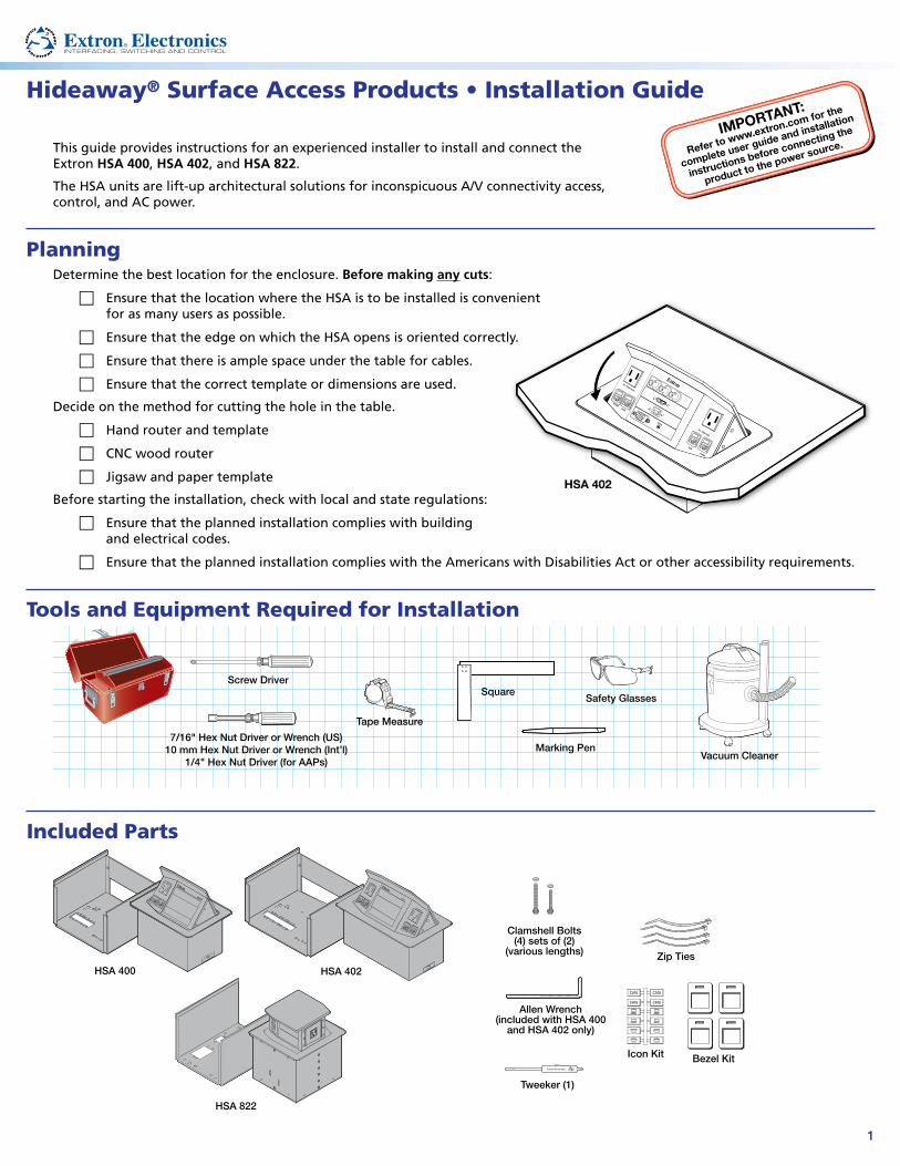
Preparing the Table
WARNING: Wear safety glasses when cutting the hole in the table. Failure to comply may result in eye injury.
CAUTIONS: • The opening in the table for the HSA should be cut only by licensed and bonded craftspeople.
• Exercise care to prevent scarring or damaging the furniture.
• Ensure that the table surface is: • at least 3/8 inch (0.325") (9.5 mm) thick and • no more than 1-3/4 inch (1.75") (44.5 mm) thick.
Cut a hole in the surface where the enclosure will be installed. There are three methods for cutting the hole in the table:
z A hand router and the appropriate Extron HSA routing template.
HSA 200
USER ACCESS
HSA 200
CABLE CUBBY 300
CABLE CUBBY 300
USER ACCESS
See the table below for part numbers. See the HSA Series and HSA Routing Template User Guide, available on the Extron website, www.extron.com, to prepare the template and use the template to cut the hole.
NOTE: The metal routing template is reusable. Do not discard this routing template when the installation is complete.
z A CNC wood router and the exact cut-out dimensions for your model. See the table below for cut-out dimensions:
z A jigsaw and a paper cut-out template (available on the Extron website, www.extron.com)
NOTE: The underlined dimension in the table below is the AAP and connector access side.
Template Part Number
Surface Cut-out Dimensions
Product Width Depth
HSA 400 (USA) 70-189-01 8.14 inches (20.68 cm) 5.95 inches (15.11 cm)
HSA 400 (Int’l) 70-189-02 9.64 inches (24.49 cm) 5.95 inches (15.11 cm)
HSA 402 (USA) 70-190-01 10.37 inches (26.34 cm) 5.95 inches (15.11 cm)
HSA 402 (Int’l) 70-190-02 13.37 inches (33.96 cm) 5.95 inches (15.11 cm)
HSA 822 (all regions) 70-191-01 8.03 inches (20.40 cm) 8.33 inches (21.16 cm)
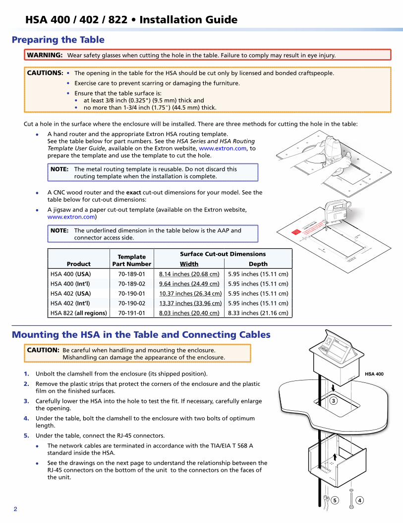
Mounting the HSA in the Table and Connecting Cables
CAUTION: Be careful when handling and mounting the enclosure. Mishandling can damage the appearance of the enclosure.
1. Unbolt the clamshell from the enclosure (its shipped position).
2. Remove the plastic strips that protect the corners of the enclosure and the plastic film on the finished surfaces.
3. Carefully lower the HSA into the hole to test the fit. If necessary, carefully enlarge the opening.
4. Under the table, bolt the clamshell to the enclosure with two bolts of optimum length.
5. Under the table, connect the RJ-45 connectors.
z The network cables are terminated in accordance with the TIA/EIA T 568 A standard inside the HSA.
z See the drawings on the next page to understand the relationship between the RJ-45 connectors on the bottom of the unit to the connectors on the faces of the unit.
3
User Access
Cut-Out Template for E
xtron's
Cable Cubby 200
.350" (0.90 cm)
Print th
is
template
at 100%
Trim Ring
Lip
Trim Ring’s Outer E
dge
0.00” (0.00 cm)
0.02 (0.05 cm)
+
1. Confirm Product to
be installed
2. Measure cutout and template
3. After c
hecking, cut opening
eg
HSA 400
COMPUTER
125 - 50/60 Hz 5A
HSA 400
3
45
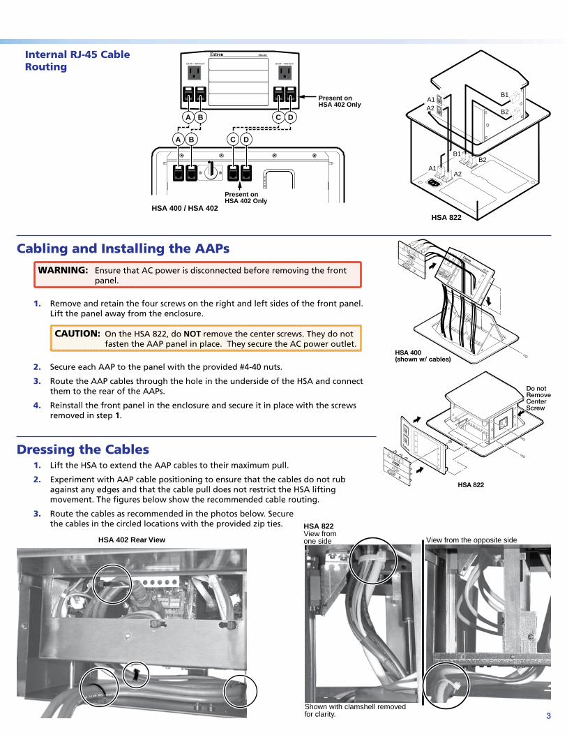
Internal RJ-45 Cable Routing
Cabling and Installing the AAPs
WARNING: Ensure that AC power is disconnected before removing the front panel.
1. Remove and retain the four screws on the right and left sides of the front panel. Lift the panel away from the enclosure.
CAUTION: On the HSA 822, do NOT remove the center screws. They do not fasten the AAP panel in place. They secure the AC power outlet.
2. Secure each AAP to the panel with the provided #4-40 nuts.
3. Route the AAP cables through the hole in the underside of the HSA and connect them to the rear of the AAPs.
4. Reinstall the front panel in the enclosure and secure it in place with the screws removed in step 1.
Dressing the Cables1. Lift the HSA to extend the AAP cables to their maximum pull.
2. Experiment with AAP cable positioning to ensure that the cables do not rub against any edges and that the cable pull does not restrict the HSA lifting movement. The figures below show the recommended cable routing.
3. Route the cables as recommended in the photos below. Secure the cables in the circled locations with the provided zip ties.
HSA 400(shown w/ cables)
HSA 400
125 - 50/60 Hz 5A
Do notRemoveCenterScrew
HSA 822
HSA 822
HSA 402 Rear View
HSA 822View fromone side
Shown with clamshell removedfor clarity.
View from the opposite side
HSA 402
120-240 50/60 Hz 5A 120-240 50/60 Hz 5A
A1A2
B1
B2
A1A2
B1B2
A B
A B C D
C D
HSA 822HSA 400 / HSA 402
Present onHSA 402 Only
Present onHSA 402 Only
HSA 400 / 402 / 822 • Installation Guide
3
Internal RJ-45 Cable Routing
Cabling and Installing the AAPs
WARNING: Ensure that AC power is disconnected before removing the front panel.
1. Remove and retain the four screws on the right and left sides of the front panel. Lift the panel away from the enclosure.
CAUTION: On the HSA 822, do NOT remove the center screws. They do not fasten the AAP panel in place. They secure the AC power outlet.
2. Secure each AAP to the panel with the provided #4-40 nuts.
3. Route the AAP cables through the hole in the underside of the HSA and connect them to the rear of the AAPs.
4. Reinstall the front panel in the enclosure and secure it in place with the screws removed in step 1.
Dressing the Cables1. Lift the HSA to extend the AAP cables to their maximum pull.
2. Experiment with AAP cable positioning to ensure that the cables do not rub against any edges and that the cable pull does not restrict the HSA lifting movement. The figures below show the recommended cable routing.
3. Route the cables as recommended in the photos below. Secure the cables in the circled locations with the provided zip ties.
HSA 400(shown w/ cables)
HSA 400
125 - 50/60 Hz 5A
Do notRemoveCenterScrew
HSA 822
HSA 822
HSA 402 Rear View
HSA 822View fromone side
Shown with clamshell removedfor clarity.
View from the opposite side
HSA 402
120-240 50/60 Hz 5A 120-240 50/60 Hz 5A
A1A2
B1
B2
A1A2
B1B2
A B
A B C D
C D
HSA 822HSA 400 / HSA 402
Present onHSA 402 Only
Present onHSA 402 Only
68-2107-50 Rev A 04 11
4
Extron USA - WestHeadquarters
+800.633.9876Inside USA/Canada Only
+1.714.491.1500+1.714.491.1517 FAX
Extron USA - East
+800.633.9876Inside USA/Canada Only
+1.919.863.1794+1.919.863.1797 FAX
Extron Europe
+800.3987.6673Inside Europe Only
+31.33.453.4040+31.33.453.4050 FAX
Extron Asia
+800.7339.8766Inside Asia Only
+65.6383.4400+65.6383.4664 FAX
Extron Japan
+81.3.3511.7655+81.3.3511.7656 FAX
Extron China
+400.883.1568Inside China Only
+86.21.3760.1568+86.21.3760.1566 FAX
Extron Middle East
+971.4.2991800+971.4.2991880 FAX
© 2011 Extron Electronics. All rights reserved. www.extron.com
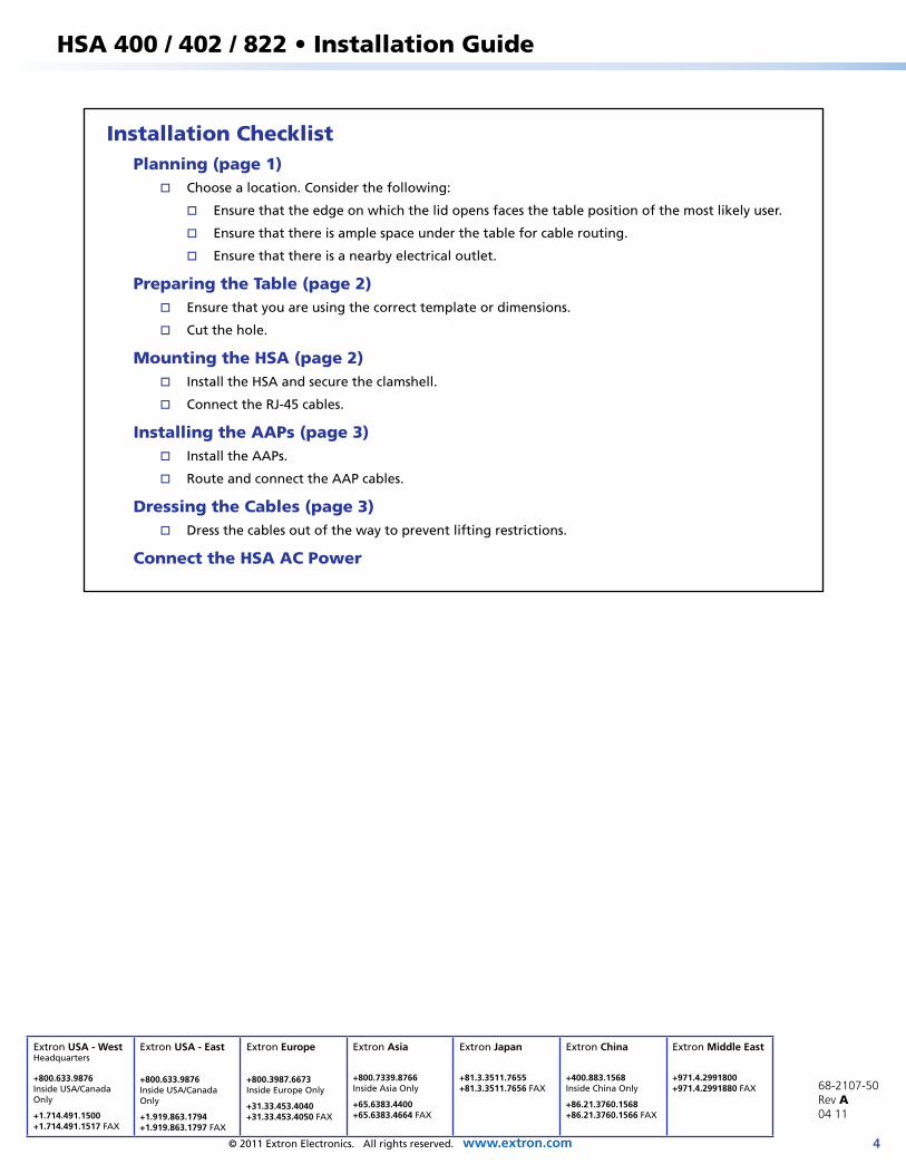
Installation ChecklistPlanning (page 1)
� Choose a location. Consider the following:
� Ensure that the edge on which the lid opens faces the table position of the most likely user.
� Ensure that there is ample space under the table for cable routing.
� Ensure that there is a nearby electrical outlet.
Preparing the Table (page 2) � Ensure that you are using the correct template or dimensions.
� Cut the hole.
Mounting the HSA (page 2) � Install the HSA and secure the clamshell.
� Connect the RJ-45 cables.
Installing the AAPs (page 3) � Install the AAPs.
� Route and connect the AAP cables.
Dressing the Cables (page 3) � Dress the cables out of the way to prevent lifting restrictions.
Connect the HSA AC Power
HSA 400 / 402 / 822 • Installation Guide