
HS1ES eriesFullSizeS olenoidLockingS witches - … · HS1E features: HS1ES eriesFullSizeS...
12
HS1E features: HS1E Series Full Size Solenoid Locking Switches • Basic unit and solenoid unit in one housing • Plastic Housing: Light weight • Ease of Wiring: All the terminal screws are M3.5 • Available with a red or green indicator • Choose from 4 circuit configurations • When mounting the actuator on a movable door, and the switch on a machine body, the door can be mechanically locked when closed • Greater Safety: The door is unlocked by a solenoid lock-release signal from a PLC or other source after the machine has stopped • In the event of power failure or for machine maintenance, the door can be unlocked using a special tool • Flexible Installation: The actuator can be accessed from two directions EN1088 EN60947-5-1 IEC60947-5-1 GS-ET-15 BG standard inGermany Certificate No. 20005010305145656 Direct Opening Action Double Insulation HS1E Series Functionality • Conduit Port Use IP67 conduit or gland. • Contact Mechanism • LED Indicator (green or red) • Terminal Block (M3.5) • Straight Actuator (Zinc Diecast) • Angle Adjustable Actuator (for hinged doors) • Right-angle Actuator • Two Actuator Entry Slots • Terminal Block for Pilot Light (M3.5) AS-Interface Safety at Work Barriers Enabling Switches Door Interlock Switches X Series E-Stops Overview Phone: 800.894.0412 - Fax: 888.723.4773 - Web: www.clrwtr.com - Email: [email protected]
Transcript of HS1ES eriesFullSizeS olenoidLockingS witches - … · HS1E features: HS1ES eriesFullSizeS...

HS1E features:
HS1E Series Full Size Solenoid Locking Switches
• Basic unit and solenoid unit in one housing• Plastic Housing: Light weight• Ease of Wiring: All the terminal screws are M3.5• Available with a red or green indicator• Choose from 4 circuit configurations• When mounting the actuator on a movable door, and the switch on a machine body, the
door can be mechanically locked when closed• Greater Safety: The door is unlocked by a solenoid lock-release signal from a PLC or
other source after the machine has stopped• In the event of power failure or for machine maintenance, the door can be unlocked
using a special tool• Flexible Installation: The actuator can be accessed from two directions
EN1088EN60947-5-1IEC60947-5-1
GS-ET-15BG standardinGermany
Certificate No.20005010305145656
Direct Opening Action Double Insulation
HS1E Series Functionality
• Conduit PortUse IP67 conduit or gland.
• Contact Mechanism
• LED Indicator (green or red)
• Terminal Block (M3.5)
• Straight Actuator
(Zinc Diecast)
•Angle Adjustable Actuator (for hinged doors)
• Right-angleActuator
• Two Actuator Entry Slots
• Terminal Block for Pilot Light (M3.5)
AS-In
terf
ace
Safe
ty a
t Wor
k Ba
rrie
rs
Enab
ling
Switc
hes
Door
Inte
rlock
Sw
itche
s X
Seri
es E
-Sto
ps
Ove
rvie
w
Phone: 800.894.0412 - Fax: 888.723.4773 - Web: www.clrwtr.com - Email: [email protected]

Part Numbers
Actuator Lock Conduit Retention Force Mechanism Contact Configuration Port Size
Model
Indicator Manual Part Number Unlock Key
1500N (when locked)
Spring Lock
Main circuit: 1NC + 1NC Monitor circuit: 1NO/1NO
1
Monitor Circuit 2
3
Main Circuit 4
5
Solenoid Power 6 Indicator
Contacts are linked to 7
the solenoid mechanically. 8
G1/2
—
—
HS1E-40R
With
—
HS1E-44R-k
—
With
HS1E-40KR
With
With
HS1E-44KR-k
Main circuit: 1NC + 1NC Monitor circuit: 1NO
1
Monitor Circuit 2
3
Main Circuit 4
5
Solenoid Power 6 Indicator
7 Contacts are linked to the solenoid mechanically. 8
G1/2
—
—
HS1E-140R
With
—
HS1E-144R-k
—
With
HS1E-140KR
With
With
HS1E-144KR-k
Main circuit: 1NC + 1NC Monitor circuit: 1NO + 1NC
1
Monitor Circuit 2
3
Main Circuit 4
5 + Solenoid Power
6 – Indicator
Contacts are linked to 7 the solenoid mechanically. 8
G1/2
—
—
HS1E-240R
With
—
HS1E-244R-k
—
With
HS1E-240KR
With
With
HS1E-244KR-k
Main circuit: 1NC + 1NC Monitor circuit: 1NC
1
Monitor Circuit 2
3
Main Circuit 4
5 + Solenoid Power
6 – Indicator
Contacts are linked to 7 the solenoid mechanically. 8
G1/2
—
—
HS1E-340R
With
—
HS1E-344R-k
—
With
HS1E-340KR
With
With
HS1E-344KR-k
1. Key wrench for TORX screws (HS9Z-T1) is supplied with the interlock switch. 2. Specify color code in place of k in the part number. G: green, R: red 3. Actuator is not supplied with the interlock switch, and must be ordered separately. 4. TORX is a registered trademark of Camcar Textron.
Actuator Keys & Accessories
Item Part Number Description
HS9Z-T1
Key Wrench (included with switch)
HS9Z-P1
Conduit Opening Plug
HS9Z-KEY1
Replacement Manual Unlocking Key
Item Part Number Description
HS9Z-A1
Straight Actuator (Mainly for sliding doors)
HS9Z-A2
Right-angle Actuator (Mainly for rotating doors)
HS9Z-A3
Adjustable Actuator
Overview
X Series E-Stops
Door Interlock Switches
Enabling Switches
Barriers AS-Interface Safety at W
ork
Phone: 800.894.0412 - Fax: 888.723.4773 - Web: www.clrwtr.com - Email: [email protected]
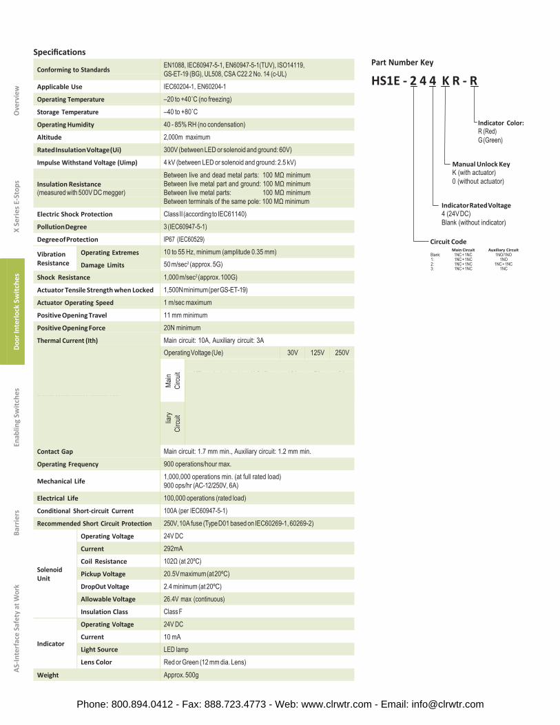
Specifications Part Number Key
HS1E - 2 4 4 K R - R
Indicator Color: R (Red) G (Green)
Manual Unlock Key K (with actuator) 0 (without actuator)
Indicator Rated Voltage 4 (24V DC) Blank (without indicator)
Circuit Code
Main Circuit Auxiliary Circuit Blank: 1NC + 1NC 1NO/1NO
Rated Operating Current (Ie)
Operating Voltage (Ue) 30V 125V 250V
AC Resistive load (AC12) Inductive load (AC15)
10A 10A
10A 5A
6A 3A
DC Resistive load (DC12) Inductive load (DC13)
6A 3A
– 0.9A
– –
AC Resistive load (AC12) Inductive load (AC15)
– –
3A –
3A 3A
Auxi
DC Resistive load (DC12) Inductive load (DC13)
3A –
– 0.9A
– –
AS-In
terf
ace
Safe
ty a
t Wor
k Ba
rrie
rs
Enab
ling
Switc
hes
Door
Inte
rlock
Sw
itche
s X
Seri
es E
-Sto
ps
Ove
rvie
w
Conforming to Standards EN1088, IEC60947-5-1, EN60947-5-1(TUV), ISO14119, GS-ET-19 (BG), UL508, CSA C22.2 No. 14 (c-UL)
Applicable Use IEC60204-1, EN60204-1 Operating Temperature –20 to +40˚C (no freezing) Storage Temperature –40 to +80˚C Operating Humidity 40 - 85% RH (no condensation) Altitude 2,000m maximum Rated Insulation Voltage (Ui) 300V (between LED or solenoid and ground: 60V) Impulse Withstand Voltage (Uimp) 4 kV (between LED or solenoid and ground: 2.5 kV)
Insulation Resistance (measured with 500V DC megger)
Between live and dead metal parts: 100 MΩ minimum Between live metal part and ground: 100 MΩ minimum Between live metal parts: 100 MΩ minimum Between terminals of the same pole: 100 MΩ minimum
Electric Shock Protection Class II (according to IEC61140) Pollution Degree 3 (IEC60947-5-1) Degree of Protection IP67 (IEC60529)
10 to 55 Hz, minimum (amplitude 0.35 mm) 50 m/sec2 (approx. 5G)
Vibration Resistance
Operating Extremes
Damage Limits
Shock Resistance 1,000 m/sec2 (approx. 100G) Actuator Tensile Strength when Locked 1,500N minimum (per GS-ET-19) Actuator Operating Speed 1 m/sec maximum Positive Opening Travel 11 mm minimum Positive Opening Force 20N minimum Thermal Current (Ith)
Contact Gap
Main circuit: 10A, Auxiliary circuit: 3A
Main
Ci
rcuit
liary
Circu
it
Main circuit: 1.7 mm min., Auxiliary circuit: 1.2 mm min. Operating Frequency 900 operations/hour max.
Mechanical Life 1,000,000 operations min. (at full rated load) 900 ops/hr (AC-12/250V, 6A)
Electrical Life 100,000 operations (rated load) Conditional Short-circuit Current 100A (per IEC60947-5-1) Recommended Short Circuit Protection 250V, 10A fuse (Type D01 based on IEC60269-1, 60269-2)
Solenoid Unit
Operating Voltage
Current
Coil Resistance
Pickup Voltage
DropOut Voltage
Allowable Voltage
Insulation Class
Operating Voltage
Current
Light Source
Lens Color
24V DC 292mA 102Ω (at 20ºC) 20.5V maximum (at 20ºC) 2.4 minimum (at 20ºC) 26.4V max (continuous) Class F 24V DC 10 mA LED lamp Red or Green (12 mm dia. Lens)
Indicator
Weight Approx. 500g
1: 1NC + 1NC 1NO 2: 1NC + 1NC 1NC + 1NC 3: 1NC + 1NC 1NC
Phone: 800.894.0412 - Fax: 888.723.4773 - Web: www.clrwtr.com - Email: [email protected]

Application Examples and Circuit DiagramsHS1E-4 (Main Circuit: 1NC-1NC, Auxiliary Circuit: 1NO/1NO)
Contacts are linked tothe solenoid mechanically
Contacts are linked tothe solenoid mechanically
Contacts are linked tothe solenoid mechanically
Contacts are linked tothe solenoid mechanically
Contacts are linked tothe solenoid mechanically
HS1E-14 (Main Circuit: 1NC-1NC, Auxiliary Circuit: 1NO)
Contacts are linked tothe solenoid mechanically
Contacts are linked tothe solenoid mechanically
Contacts are linked tothe solenoid mechanically
Contacts are linked tothe solenoid mechanically
Contacts are linked tothe solenoid mechanically
1. Main Circuit: used to enable the machine to start only when the main circuit is closed.2. Auxiliary Circuit: used to indicate whether the machine circuit or door is open or closed.3. Terminals 7 and 8 are used for the LED indicator, and are isolated from solenoid and door status.
(Note)
Overview
X Series E-Stops
Door Interlock Switches
Enabling Switches
Barriers AS-Interface Safety at W
ork
Status 1 Status 2 Status 3 Status 4 Unlocked Manually
Switch/DoorStatus
• Door Closed• Machine ready to operate• Solenoid de-energized
• Door Closed• Machine cannot be started• Solenoid de-energized
• Door Opened• Machine cannot be started• Solenoidenergized
• Door Opened• Machine cannot be started• Solenoid de-energized
• Door Closed• Machine cannot be started• Solenoid de-energized
Door
Circuit Diagram
Sole
noid
Mai
nM
onito
r Po
wer
Circ
uit
C
ircui
t
Sole
noid
Mai
nM
onito
r Po
wer
Circ
uit
C
ircui
t
Sole
noid
Mai
nM
onito
r Po
wer
Circ
uit
C
ircui
t
Sole
noid
Mai
nM
onito
r Po
wer
Circ
uit
C
ircui
t
Sole
noid
Mai
nM
onito
r Po
wer
Circ
uit
C
ircui
t
Main Circuit 3-4: Closed 3-4: Open 3-4: Open 3-4: Closed 3-4: OpenAux. Circuit 1-2: Open 1-2: Closed 1-2: Closed 1-2: Closed 1-2: Closed
Solenoid 5-6: Power OFF 5-6: Power ON 5-6: Power ON 5-6: Power OFF 5-6: Power OFF
Status 1 Status 2 Status 3 Status 4 Unlocked Manually
Switch/DoorStatus
• Door Closed• Machine ready to operate• Solenoid de-energized
• Door Closed• Machine cannot be started• Solenoidenergized
• Door Opened• Machine cannot be started• Solenoidenergized
• Door Opened• Machine cannot be started• Solenoid de-energized
• Door Closed• Machine cannot be started• Solenoid de-energized
Door
Circuit Diagram
Sole
noid
Mai
nM
onito
r Po
wer
Circ
uit
C
ircui
t
Sole
noid
Mai
nM
onito
r Po
wer
Circ
uit
C
ircui
t
Sole
noid
Mai
nM
onito
r Po
wer
Circ
uit
C
ircui
t
Sole
noid
Mai
nM
onito
r Po
wer
Circ
uit
C
ircui
t
Sole
noid
Mai
nM
onito
r Po
wer
Circ
uit
C
ircui
t
Main Circuit 3-4: Closed 3-4: Open 3-4: Open 3-4: Open 3-4: OpenAux. Circuit 1-2: Open 1-2: Open 1-2: Closed 1-2: Closed 1-2: Open
Solenoid 5-6: Power OFF 5-6: Power ON 5-6: Power ON 5-6: Power OFF 5-6: Power OFF
Phone: 800.894.0412 - Fax: 888.723.4773 - Web: www.clrwtr.com - Email: [email protected]

Application Examples and Circuit Diagrams, continuedHS1E-24 (Main Circuit: 1NC+1NC, Auxiliary Circuit: 1NC+NC)
Contacts are linked to the solenoid mechanically
Contacts are linked to the solenoid mechanically
Contacts are linked to the solenoid mechanically
Contacts are linked to the solenoid mechanically
Contacts are linked to the solenoid mechanically
HS1E-34 (Main Circuit: 1NC+1NC, Auxiliary Circuit: 1NC)
Contacts are linked to the solenoid mechanically
Contacts are linked to the solenoid mechanically
Contacts are linked to the solenoid mechanically
(Note)
Contacts are linked to the solenoid mechanically
Contacts are linked to the solenoid mechanically
1. Main Circuit: used to enable the machine to start only when the main circuit is closed.2. Auxiliary Circuit: used to indicate whether the machine circuit or door is open or closed.3. Terminals 7 and 8 are used for the LED indicator, and are isolated from solenoid or door status.
AS-In
terf
ace
Safe
ty a
t Wor
k Ba
rrie
rs
Enab
ling
Switc
hes
Door
Inte
rlock
Sw
itche
s X
Seri
es E
-Sto
ps
Ove
rvie
w Status 1 Status 2 Status 3 Status 4 Unlocked Manually
Switch/DoorStatus
• Door Closed• Machine ready to operate• Solenoid de-energized
• Door Closed• Machine cannot be started• Solenoidenergized
• Door Opened• Machine cannot be started• Solenoidenergized
• Door Opened• Machine cannot be started• Solenoid de-energized
• Door Closed• Machine cannot be started• Solenoid de-energized
Door
Circuit Diagram
Sole
noid
Mai
nM
onito
r Po
wer
Circ
uit
C
ircui
t
Sole
noid
Mai
nM
onito
r Po
wer
Circ
uit
C
ircui
t
Sole
noid
Mai
nM
onito
r Po
wer
Circ
uit
C
ircui
t
Sole
noid
Mai
nM
onito
r Po
wer
Circ
uit
C
ircui
t
Sole
noid
Mai
nM
onito
r Po
wer
Circ
uit
C
ircui
t
Main Circuit 3-4: Closed 3-4: Open 3-4: Open 3-4: Open 3-4: OpenAux. Circuit 1-2: Closed 1-2: Open 1-2: Open 1-2: Open 1-2: Open
Solenoid 5-6: Power OFF 5-6: Power ON 5-6: Power ON 5-6: Power OFF 5-6: Power OFF
Status 1 Status 2 Status 3 Status 4 Unlocked Manually
Switch/DoorStatus
• Door Closed• Machine ready to operate• Solenoid de-energized
• Door Closed• Machine cannot be started• Solenoidenergized
• Door Opened• Machine cannot be started• Solenoidenergized
• Door Opened• Machine cannot be started• Solenoid de-energized
• Door Closed• Machine cannot be started• Solenoid de-energized
Door
Circuit Diagram
Sole
noid
Mai
nM
onito
r Po
wer
Circ
uit
C
ircui
t
Sole
noid
Mai
nM
onito
r Po
wer
Circ
uit
C
ircui
t
Sole
noid
Mai
nM
onito
r Po
wer
Circ
uit
C
ircui
t
Sole
noid
Mai
nM
onito
r Po
wer
Circ
uit
C
ircui
t
Sole
noid
Mai
nM
onito
r Po
wer
Circ
uit
C
ircui
t
Main Circuit 3-4: Closed 3-4: Open 3-4: Open 3-4: Open 3-4: OpenAux. Circuit 1-2: Closed 1-2: Closed 1-2: Open 1-2: Open 1-2: Closed
Solenoid 5-6: Power OFF 5-6: Power ON 5-6: Power ON 5-6: Power OFF 5-6: Power OFF
Phone: 800.894.0412 - Fax: 888.723.4773 - Web: www.clrwtr.com - Email: [email protected]
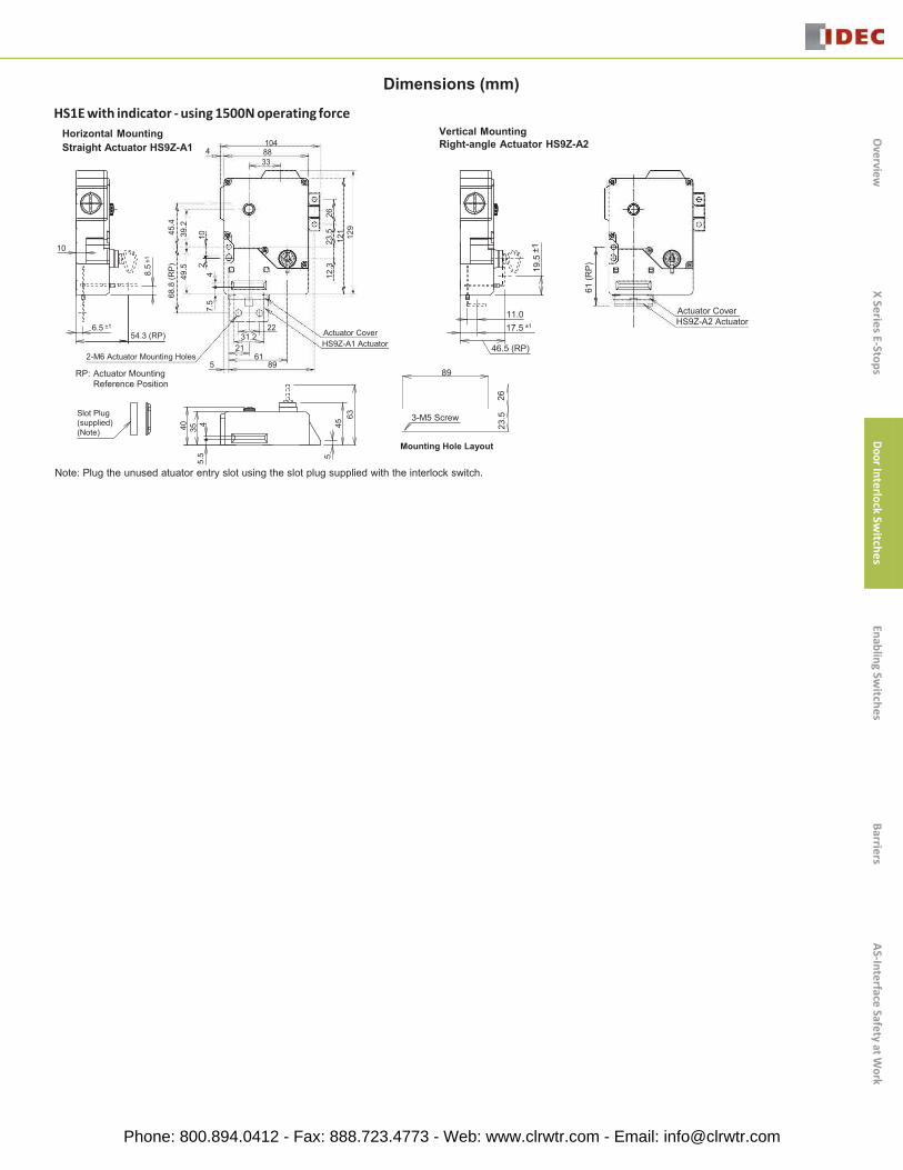
HS1E with indicator - using 1500N operating force Horizontal Mounting
Dimensions (mm)
Vertical MountingStraight Actuator HS9Z-A1 4
1048833
Right-angle Actuator HS9Z-A2
10
6.5 ±1
54.3 (RP)22
31.221
Actuator Cover HS9Z-A1 Actuator
2-M6 Actuator Mounting Holes 615 89
RP: Actuator Mounting 89Reference Position
Mounting Hole Layout
Note: Plug the unused atuator entry slot using the slot plug supplied with the interlock switch.
Actuator Cover HS9Z-A2 Actuator
11.017.5 ±1
46.5 (RP)
Slot Plug (supplied) (Note)
Overview
X Series E-Stops
Door Interlock Switches
Enabling Switches
Barriers AS-Interface Safety at W
ork
8.5
±1
68.8
(RP)
49.5
45.4
39.2
40 354
5.5
210
7.5
4
512
.323
.512
1 129
2645
63
23.5
19.5
±1
61 (R
P)
26
3-M5 Screw
Phone: 800.894.0412 - Fax: 888.723.4773 - Web: www.clrwtr.com - Email: [email protected]

Straight Actuator (mainly for sliding doors) HS9Z-A1
2-M6Screws
ActuatorMountingHoles
Right-angle Actuator (mainly for hinged doors) HS9Z-A2 20
11
Accessories
*After installing the actuator,remove the actuator cover.
2- M6 Screws
ActuatorMountingHoles
7.4
Adjustable Actuator
• The actuator angle is adjustable (0˚ to 20˚) for hinged doors.
• The minimum radius of the door opening can be as small as 100mm.
For HS1/HS2 Series (HS9Z-A3)
(Note) 18Actuator StopFilm (attached)
5 220 Door hinge
Angle Adjustment Screw(M3 hexagon socket head screw)
ActuatorMounting Holes
All dimensions in mm.
9 49.319.31
7.4 Actuator Cover(red)
41.511.5
1
Actuator Cover(red)
2
30
2-M6 Screws
AS-In
terf
ace
Safe
ty a
t Wor
k Ba
rrie
rs
Enab
ling
Switc
hes
Door
Inte
rlock
Sw
itche
s X
Seri
es E
-Sto
ps
Ove
rvie
w
33m
ax.
12(2
1)1
2222 40 22
2
22
29.2
404.
129
.243
44 58 72
29.2
4358
Phone: 800.894.0412 - Fax: 888.723.4773 - Web: www.clrwtr.com - Email: [email protected]
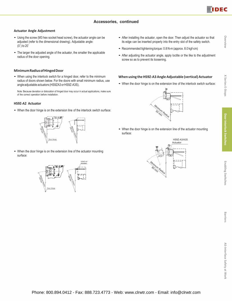
Accessories, continued
Actuator Angle Adjustment
• Using the screw (M3 hex socket head screw), the actuator angle can beadjusted (refer to the dimensional drawing). Adjustable angle:(0˚) to 20˚
• The larger the adjusted angle of the actuator, the smaller the applicableradius of the door opening.
• After installing the actuator, open the door. Then adjust the actuator so thatits edge can be inserted properly into the entry slot of the safety switch.
• Recommended tightening torque: 0.8 N-m (approx. 8.0 kgf-cm)
• After adjusting the actuator angle, apply loctite or the like to the adjustmentscrew so as to prevent its loosening.
Minimum Radius of Hinged Door • When using the interlock switch for a hinged door, refer to the minimum
radius of doors shown below. For the doors with small minimum radius, useangleadjustable actuators (HS9ZA3 orHS9Z-A3S).
Note: Because deviation or dislocation of hinged door may occur in actual applications, make sureof the correct operation before installation.
HS9Z-A2 Actuator
When using the HS9Z-A3 Angle Adjustable (vertical) Actuator
• When the door hinge is on the extension line of the interlock switch surface:
• When the door hinge is on the extension line of the interlock switch surface:
• When the door hinge is on the extension line of the actuator mounting surface:
HS9Z-A3/A3SActuator
• When the door hinge is on the extension line of the actuator mounting surface:
HS9Z-A2Actuator
Door Hinge
Door Hinge
Overview
X Series E-Stops
Door InterlockSw
itches Enabling Sw
itches Barriers
AS-Interface Safety at Work
Phone: 800.894.0412 - Fax: 888.723.4773 - Web: www.clrwtr.com - Email: [email protected]

Safety Precautions
• In order to avoid electric shock or a fire, turn the power off before installation, removal, wire connection, maintenance, or inspection of the switch.
• If relays are used in the circuit between the safety switch and the load, consider degrees of the danger and use safety relays, since welded or sticking contacts of standard relays may invalidate the functions of the safety switch.
• Do not place a PLC in the circuit between the safety switch and the load. The safety security can be endangered in the event of a malfunction of the PLC.
• Do not disassemble or modify the switch. It may cause a breakdown or an accident.
Operation Precautions - for all series • Regardless of door types, do not use the safety switch as a door stop. Install
a mechanical door stop at the end of the door to protect the safety switch against excessive force.
• Do not apply excessive shock to the switch when opening or closing the door.
• A shock to the door exceeding 1,000 m/sec2 (approx. 100G) may cause the contacts of the switch to chatter, and a malfunction of the switch may occur.
• For connection of wires, unscrew the cover. Unnecessary loosening of other screws may cause a malfunction of the switch.
• Prevent foreign objects such as dust and liquids from entering the switch while connecting conduit or wiring.
• If the operating atmosphere is contaminated, use a protective cover to prevent the entry of foreign objects into the switch through the actuator entry slots.
• Entry of a considerable amount of foreign objects into the switch may affect the mechanism of the switch and cause a breakdown.
• Do not store the switches in a dusty, humid, or organic-gas atmosphere.
For Rotating Head Directions
HS5E/HS5B Precautions Note: Because deviation or dislocation of hinged doors may occur in actual applications, make sure of the correct operation before installation.
• The heads of the HS5E/HS5B can be rotated in 90° increments after removingthe 4 screws on the corners of the head. Prevent entry of foreign objects into the switch during removal of the head. Tighten these screws with torque designated in the instruction sheet. Improper torque may cause errors.
When using the HS9Z-A52 Actuator
• When the door hinge is on the extension line of the interlock switch surface:
Door Hinge Door Hinge
• When door hinge is on the extension line of the actuator mounting surface:
Minimum Radius of Hinged Doors
• When using the interlock switch on hinged doors, refer to the minimum radius of doors shown below. When using on doors with small minimum radius, use the angle adjustable actuator (HS9Z-A55).
Wire Connection
HS2B Precautions• Cracks or burrs on the conduit entry may deteriorate the housing protection
against water. • The HS2B has 3 conduit ports, which are closed as a part of the molded
switch housing.
• Make an opening for wire connection by breaking one of the conduit-port knockouts on the switch housing using a screwdriver.
• When breaking the conduit port, take care not to damage the contact block or other parts inside the switch.
• When changing to another conduit port, close the unused opening with an optional plug (Part No. HS9Z-P1).
Door Hinge
Overview
X Series E-Stops
Door InterlockSw
itches Enabling Sw
itchesBarriers
AS-Interface Safety at Work
Factory Setting Head can be rotated.
Door Hinge
Phone: 800.894.0412 - Fax: 888.723.4773 - Web: www.clrwtr.com - Email: [email protected]

HS1E Precautions
Wire Connection
• Make an opening for wire connection by breaking one of the conduit-port knockouts on the switch housing using a screwdriver.
• Before breaking the knockout, temporarily remove the connector-fixing lock nut from the switch.
• When breaking the knockout, take care not to damage the contact block or other parts inside the switch.
• Cracks or burrs on the conduit entry may deteriorate the housing protection.
• When changing to the other conduit port, close the unused opening with an optional plug (accessory).
1. This unlocking method is intended for an escape from a machine when a person is locked in. For access to the unlocking entry, an access hole should be opened on the mounting panel. When opening the hole, apply proper protection against water or other foreign objects.
2. Caution: After the unlocking operation, put the screw back into the unlocking entry for safety.
PlugType No. HS9Z-P1
Unlock
Normal Position
Unlock
Manual Unlocking Position
Manual Unlocking
• Remove the screw located on the unlocking entry at the side of the switch us- ing the key wrench included with the switch. Then insert a small screwdriver into the switch to push the lever inside of the switch toward the indicator until the actuator is unlocked (refer to the diagram on the right).
• Insert a small screwdriver into the elliptical hole on the back of the switch, then push the lever inside of the switch toward the indicator until the actuator is unlocked (refer to the diagram on the right).
HS1C Precautions• Regardless of door type, do not use the safety switch as a locking device.
Install a locking device independently, for example, using a metal latch (also applicable to HS1E).
• The safety switch cover can be only removed with the special key wrench supplied with the switch or with the optional screwdriver (also applicable to HS1B and HS1E).
• Remove the screw located on the unlocking entry at the side of the switch us- ing the key wrench included with the switch. Then insert a small screwdriver into the switch to push the lever inside of the switch toward the indicator until the actuator is unlocked (refer to the diagram on the right).
Caution: After the unlocking operation, put the screw back into the unlocking entry for safety.
Screwdriver
Screwdriver
AS-In
terf
ace
Safe
ty a
t Wor
k Ba
rrie
rs
Enab
ling
Switc
hes
Door
Inte
rlock
Sw
itche
s X
Seri
es E
-Sto
ps
Ove
rvie
w
M5
23.5
26
Phone: 800.894.0412 - Fax: 888.723.4773 - Web: www.clrwtr.com - Email: [email protected]

Operation Precautions
Applicable Crimping Terminals
• (Refer to the Crimping Terminal 1 or 2 shown in the drawing below.)
• HS1C Terminals No. 1 to 6: Use solid or stranded wires only (crimping terminals not applicable). Terminals No. 7 and 8: Crimping Terminal 1 Ground Terminal: Crimping Terminal 2
• HS1B Ground Terminal: Crimping Terminal 2 Other Terminals: Crimping Terminal 1 HS2B, HS5B, and HS1E Crimping Terminal 1
3.6 min. 3.5 max.
ø3.6 min.
Applicable Connectors (As shown below)
• Use connectors which maintain the IP67 protection.
• Applicable Connector Dimensions
• Flex Conduit: VF03 (Japan Flex) www.nipolex.co.jp
• Steel Connector (G1/2): ALC-103 (PF13.5): RBC-103PG13.5
G1/2
Recommended Screw Tightening Torque
• HS1C: 5.0±0.5 N-m (approx. 50±5 kgf-cm) (4 or 6 pcs of M5 hex socket head cap screws)
• HS1B: 5.0±0.5 N-m (approx. 50±5 kgf-cm) Crimping Terminal 1
Use an insulation tube on the crimping terminal.
Crimping Terminal 2 (2 or 4 pcs. of M5 hex socket head cap screws)
• HS2B: 5.0±0.5 N-m (approx. 50±5 kgf-cm) (2 pcs of M5 hex socket head cap screws)
Wire Approx. 4mm Crimping Terminal • HS5B: 4.0±0.4 N-m (approx. 40±4 kgf-cm) (2 pcs of M4 hex socket head cap screws)
• HS1E: 5.0±0.5 N-m (approx. 50±5 kgf-cm) Insulation Tube
Installation Examples (see the diagrams below) Mounting on Sliding Doors
Door
HS9Z-A1 Actuator
Door Stop
Mounting on Hinged Doors
HS9Z-A1 Actuator
(4 or 6 pcs of M5 hex socket head cap screws)
• Actuator (HS9Z-A1/A2) 5.0±0.5 N-m (approx. 50±5 kgf·cm)
• (2 pcs. of M6 hex socket head cap screws) Actuator (HS9Z-A51/A52)
• 2.0±0.2 N-m (approx. 20±2 kgf·cm)(2 pcs of M4 hex socket head cap screws)
• 1.0±0.2 N-m (approx. 10±2 kgf·cm) (2 pcs of M4 Phillips screws)
The screws are supplied by the user.
Applicable Wire Size
• HS1C: 0.5 to 0.75 mm2 (Terminals No.1, 2, 5 to 8) 1.0 to 1.25 mm2 (Terminals No.3, 4, and grounding terminal)
• HS5B: 0.5 to 1.25 mm2
• HS1E: 0.5 to 1.25 mm2
Latch
9 mm max.
3.5 min. 3.8 max.
ø4.1 min.
HS9Z-A2 Actuator
Overview
X Series E-Stops
Door Interlock Switches
Enabling Switches
Barriers AS-Interface Safety at W
ork
6.9
max
.
7.6
max
.
30 m
m
max
.
Phone: 800.894.0412 - Fax: 888.723.4773 - Web: www.clrwtr.com - Email: [email protected]
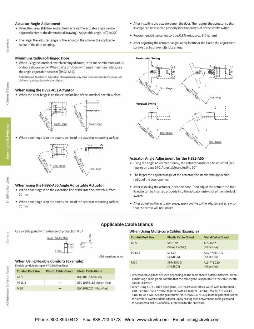
Actuator Angle Adjustment • Using the screw (M3 hex socket head screw), the actuator angle can be
adjusted (refer to the dimensional drawing). Adjustable angle: (0˚) to 20˚
• The larger the adjusted angle of the actuator, the smaller the applicable radius of the door opening.
• After installing the actuator, open the door. Then adjust the actuator so that its edge can be inserted properly into the entry slot of the safety switch.
• Recommended tightening torque: 0.8 N-m (approx. 8.0 kgf-cm)
• After adjusting the actuator angle, apply loctite or the like to the adjustment screw so as to prevent its loosening.
Minimum Radius of Hinged Door • When using the interlock switch on hinged doors, refer to the minimum radius
of doors shown below. When using on doors with small minimum radius, use the angle adjustable actuator (HS9Z-A55). Note: Because deviation or dislocation of hinged doors may occur in actual applications, make sure of the correct operation before installation.
When using the HS9Z-A52 Actuator • When the door hinge is on the extension line of the interlock switch surface:
Horizontal Swing
Vertical Swing
Door Hinge Door Hinge
• When door hinge is on the extension line of the actuator mounting surface:
When using the HS9Z-A55 Angle Adjustable Actuator • When door hinge is on the extension line of the interlock switch surface:
50 mm
• When door hinge is on the extension line of the actuator mounting surface: 70 mm
Actuator Angle Adjustment for the HS9Z-A55 • Using the angle adjustment screw, the actuator angle can be adjusted (see
figures on page 370. Adjustable angle: 0 to 20°
• The larger the adjusted angle of the actuator, the smaller the applicable radius of the door opening.
• After installing the actuator, open the door. Then adjust the actuator so that its edge can be inserted properly into the actuator entry slot of the interlock switch.
• After adjusting the actuator angle, apply Loctite to the adjustment screw so that the screw will not loosen.
Use a cable gland with a degree of protection IP67
G1/2, PG13.5, M20
Applicable Cable Glands When Using Multi-core Cables (Example)
When Using Flexible Conduits (Example) Flexible conduit example: VF-03 (Nihon Flex)
all dimensions in mm
• Different cable glands are used depending on the cable sheath outside diameter. When purchasing a cable gland, confirm that the cable gland is applicable to the cable sheath outside diameter.
• When using a 1/2-14NPT cable gland, use the HS5B interlock switch with M20 conduit port (Part No.: HS5B-***BM) together with an adapter (Part No.: MA-M/NPT 20X1.5 5402-0110, K-MECS) and a gasket (Part No.: GP M20, K-MECS). Install a gasket between the interlock switch and the adapter. Apply sealing tape between the cable gland and the adapter to make sure of IP67 protection for the enclosure.
9 max.
Door Hinge
Door Hinge
Door Hinge
Door Hinge
Door Hinge
AS-In
terf
ace
Safe
ty a
t Wor
k Ba
rrie
rs
Enab
ling
Switc
hes
Door
Inte
rlock
Sw
itche
s X
Seri
es E
-Sto
ps
Ove
rvie
w
30 m
ax.
Door Hinge
Conduit Port Size Plastic Cable Gland Metal Cable Gland
G1/2 SCS-10* (Seiwa Electric)
ALS-16** (Nihon Flex)
PG13.5 ST13.5 (K-MECS)
ABS-**PG13.5 (Nihon Flex)
M20 ST-M20X1.5 (K-MECS)
ALS-**EC20 (Nihon Flex)
Conduit Port Size Plastic Cable Gland Metal Cable Gland
G1/2 — RLC-103 (Nihon Flex)
PG13.5 — RBC-103PG13.5 (Nihon Flex)
M20 — RLC-103EC20 (Nihon Flex)
Phone: 800.894.0412 - Fax: 888.723.4773 - Web: www.clrwtr.com - Email: [email protected]


![Python logic Tell me what you do with witches? Burn And what do you burn apart from witches? More witches! Shh! Wood! So, why do witches burn? [pause]](https://static.fdocuments.in/doc/165x107/56649d385503460f94a11ef5/python-logic-tell-me-what-you-do-with-witches-burn-and-what-do-you-burn-apart.jpg)


