HS11200-1105 - hes
48
Transcript of HS11200-1105 - hes

2
===== CONTENT ===== Chapter 1 Safety Rules
1.0 Introduction……………………………………………………………….6
1.1 Safety Rules in Installation……………………………………………...6
1.2 Safety Rules in Operatio…………………………………………………6
1.3 Cautions in Using the Machine………………………………………….6
1.4 Safety Items in Maintenance…………………………………………….7
1.5 Safety Items in Using Hot Melt and Solvent……………………………7
Chapter 2 Machinen Familirization
2.0 Introduction……………………………………………………………….9
2.1 Specification……………………………………………………………...10
2.2 Mechanic Characteristics……………………………………………….13
2.3 Function of the Equipment……………………………………………..13
2.3.1 Drive System…………………………………………………………...13
2.3.2 Hydraulic System……………………………………………………...14
2.3.3 Electrical System………………………………………………………16
Chapter 3 Unpacking and Installation
3.0 Introduction……………………………………………………………...18

3
3.1 Unpacking the Machine…………………………………………………18
3.2 Check the Machine………………………………………………………18
3.3 Install the Mahcine……………………………………………………...18
3.4 Installation of the Hose And Nozzle Assembly………………………..19
3.5 Installation of Power…………………………………………………….19
Chapter 4 Operation Instrucitons
4.0 Introduction……………………………………………………………...20
4.1 Safety Precaution………………………………………………………..20
4.2 Function of the Control Panel………………………………………….20
4.3 Preparation befoore Operation………………………………………...21
4.4 Starting the Machine……………………………………………………21
4.5 General Adjustment of Nozzle Assembly……………………………..21
4.6 Shutting Down Steps…………………………………………………….21
Chapter 5 Precautions and Maintenance
5.0 Introduction……………………………………………………………...22
5.1 Safety Precautions……………………………………………………….22
5.2 Daily Maintenance Items……………………………………………….22
5.3 Monthly Maintenance Items……………………………………………22
4
5.4 Regular Maintenance……………………………………………………22
5.4.1 General Maintenance…………………………………………………23
5.4.2 Clearing the Hydraulic System………………………………………23
5.4.3 Clearing the Nozzle Assembly………………………………………..24
Chapter 6 Disassembling and Servicing
6.0 Introduction………………………………..…………………………….25
6.1 Safety Precautions………………………………..……………………..25
6.2 Disasembly and Servicing of Hydraulic System………………………26
6.2.1 Filter Assembly……………………………………………………….26
6.2.2 Disassembling Piston Pump…………………………………………27
Chapter 7 Trouble Shooting
7.0 Introduction……………………………………………………………...30
7.1 Safety Precautions………………………………………………………30
7.2 Trouble Shooting on Mechanic & Electric…………………………….30
7.3 Trouble Shooting on Hot Melt Coating………………………………..35
Chapter 8 Drawings of Spare Parts
8.1 Assembly Drawing of Metal Plates…………………………………….38
8.2 Pump Assembly………………………………………………………….41

5
8.3 Filter Assembly…………………………………………………………..43
8.4 Tank Assembly…………………………………………...….…..………44
Chapter 9 Wiring Diagram
9.1 11200ET01………………………………………………………………..45
9.2 11200ET02………………………………………………………………..46
9.3 11200ET03………………………………………………………………..47
9.4 1104-1AIR………………………………………………………………..47
6
Chapter 1 Safety Summary 1.0 Introduction This chapter intends as an introduction to the installation, operation and maintenance of hot melt
applicator HS11200-1105. It sets out the safety rules to be observed for preventing risks both to personnel and to the equipment.
This risk prevention rules may be classified as following: 1. Safety Rules in installation. 2. Cautions in using. 3. Safety Rules in maintenance. 4. Safety Rules in using of hot melt and solvents.
1.1 Safety Rules in installation. 1. Establish correct and effective ground connection for entire apparatus (before installation) . Without such
connection, every element of apparatus, even though apparently insulated, becomes a potential conductor and poses a risk of electrical shock.
2. Check that the power cords and their insulation are correctly dimensioned for the load constituted by the apparatus completed with all accessories.
3. Ensure that electronic power, which connects with electronic flex, is consistent with required electronic power of hot melt applicator and check that the power cords correctly connected with a breaker.
4. Always operate the apparatus in accordance with the recommended current and voltage. If working voltage is different from recommended voltages and currents, this may cause fire.
5. When installing hose try to avoid it being twisted, rubbed or scratched. 1.2 Safety Rules in operation. 1. Do not operate the equipment near volatile or explosive gases or materials. 2. Do not operate the equipment that the covers, panels or safety guards have not been installed properly. 3. Do not operate the equipment at a temperature over 50℃ or below 0℃. 4. Avoid to put the hose in air-tight container. 5. Keep the hose away from ground or cold surface if the hose is long. 6. If any part of the hose is cooled, this will cause hot melt to flow unsmooth. More seriously this will get the
hose jammed. 1.3 Cautions in using: 1. When using the hot melt applicator, do not put anything on the top of the machine body and do not take it as
something to help you to step higher.
7
2. Only the base of the hot melt applicator can be used while moving or lifting the machine. Do not lift the machine with any of the out stretched parts on the control panel.
3. Do not fold the hose at R<150mm. 4. If a glue gun is used, never point it to anybody. Note: The ength of hose for this machine cannot exceed 2.4 meters. 1.4 Safety Items in Maintenance.
Please observe the following major precautions in the maintenance of hot melt applicator. 1. Cut off the main power before maintenance. 2. The worker should not wear rings, watch, necklace, bracelets or any other conductive decorations while
servicing the machine. 3. Should there be no personnel assistance, do not dismantle, check or adjust any part of the machine. 4. Only qualified staff can do the maintenance. 5. Do not touch any exposed electric cord terminal or any other power-on and unloosened component. 6. Power supply must be turned off before dismantling and removal of protective devices on the machine, or
before the replacement of electric components. 7. If possible, try to stand on plastic carpet to work on maintenance. Never do it on floor with water or in
extremely humid environment. 8. Always wear safety gloves, safety glasses and long-sleeved uniform to keep body from being burned by hot
melt applicator or hot component surface. 9. In order to prevent the inner surface of the tank from being scratched, do not use flammable or sharp tools
during cleaning the tank. 10. Never operating the machine if compressed air or hot melt leaks. 1.5 Safety Items in Using Hot Melt and Solvent
1)Hot Melt The following items should be noted when using hot melt of hi-temperature.
----Hot melt can instantly be cooled down from liquid into solid. Although the outer surface is solid, the inner part may remain hot. Once hot melt touches people’s skin, it will cause severe injury. ----Be sure to have worn safety uniform, safety gloves and protective glasses before filling adhesive into tank or when working close to the machine.
2) Heating solvent, namely cleaner ----Never heat parts with open flames or fixed-temp. heating apparatus while cleaning parts with heated cleaner. ---- Solvent of high volatility cannot be used to clean glued components. Because it is easy to cause flaming or exposing with this kind of solvent. And it can give off poisonous gases at high temperature.

8
----Before using the cleaner, keep the room ventilated. ----In order to avoid taking in too much poisonous gas caused by high temperature, do not work long hours when working with cleaner. Cautions:
If skin is burned by liquid hot melt adhesive, you should put wounded place into clean and icy water (or wash the wounded part in the water) instead of wiping it at once. After the hot melt adhesive stuck on the skin cool down completely, cover the place with clean and wet bandage. If it is a serious injury or the injury area is too big, it will lead to wound or death. Or the wounded part will tend to get inflamed. The wounded person should keep normal body temperature and send to hospital immediately.

9
Chapter 2 Machine Familiarization
2.0 Introduction
This chapter intends to provide the users with general specifications, structures and working conditions of the 11200-1105 hot melt applicator .It is attached with the overall diagram of the machine as a reference to the assembly of the machine. Besides, the flowchart of the hydraulic system and the electrical control system are also given.
Fig2.1 Outside View of Hot Melt Applicator HS11200-1105

10
2.1 Specification
Note: Meting rate will vary depending on hot melt type.
Item HS11200-1105
Tank Capacity (Liter) 5 Melting Rate (Kg/hr) 7
Viscosity(CPS) 500~200,000 Power (W) 2000
Dimension (mm) 400*380*575 Weight (Kg) 38
Air Pressure(Kg/㎠) 0.5-4 Max. Viscosity (CPS) 12,000
Operating Temperature. ( )℃ Max. 220 Hose (Set) 1
11
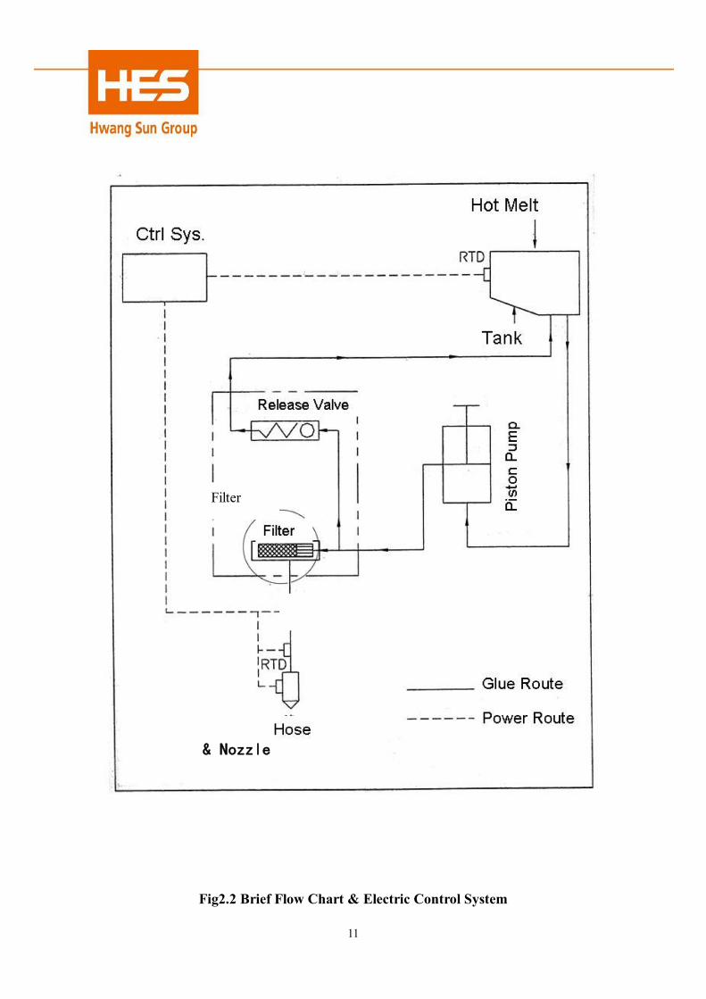
Fig2.2 Brief Flow Chart & Electric Control System
Filter
Release Valve
Piston Pump Piston Pump
& Nozzle

12
13
2.2 Mechanical characteristics The design of the hot melt applicator suits to melt hot melt of all types and forms. The applicable viscosity ranges from 500cps to 200,000 cps. Piston pump is used in this machine.
It can be divided into two major parts, the electronic control system and the heating system. And the heating system includes the hydraulic system and pneumatic system. The adoption of double-layer glass fiber, around and under the melting tank, can efficiently reduce the heat on the surface of the machine, and can prevent operator from being burnt.
Solid adhesive in the tank is melt into liquid and flows to the bottom of the tank. The adhesive is collected around the Dual-Action Piston Pump. When the piston pump actions, the melted hot melt adhesive is absorbed into the cylinder pump and is pushed through the heating board into the manifold simultaneously. After passing the filter assembly, the hot melt adhesive flows out the manifold and goes into the hose. In the other side of the hose is connected with a nozzle assembly or a hot melt gun, and then the adhesive can be used through these devices. The extrusion strength is max. 60Kg/cm2 . The machine suits for automatic coating line well.
2.3 Function of the equipment 2.3.1 Drive System The major drive system of hot melt applicator HS11200-1105 is cylinder drive system. As shown in fig2.2, cylinder is connected to dual-action piston pump. That the cylinder’s pistons run upward and downward drives the dual-action piston pump to action simultaneously. And the latter absorb HMA from the melting tank and meanwhile extrude the HMA inside out. The Limit Switches controls the operation of the Solenoid Valve to act the cylinder pump and the dual-action piston pump at the same time.
14
2.3.2 Hydraulic System
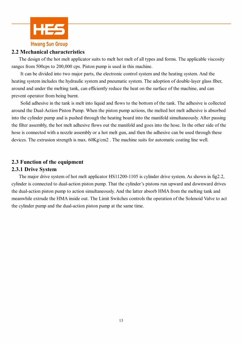
Fig2.3 Hydraulic System
1. Melt Tank The heater at the bottom of the tank melts the solid adhesive into the liquid status. And the adhesive
flows to devices of the hydraulic system. The Teflon material coated on the internal wall not only avoids hot melt adhesive being stuck on the wall, but also facilitates the replacement of the adhesive. Besides, lips on the internal wall increase the heat conducting area. A resistant temperature detector (RTD) beneath the tank detects the tank temperature and sends relevant signals to the temperature controller for effectively controlling the tank temperature.
15
2. Cylinder Pump Cylinder pump can be divided into two sections, i.e. drive system (the cylinder) and hydraulic system
(the Dual-Action Piston Pump, which is installed inside the tank). As the Fig 7.4 shows, no matter the piston is running upward or downward, HMA can be absorbed into the Dual-Action Piston Pump, meanwhile hot melt will be led to manifold continuously.
The combination of the Lower Check Valve (at top of the cylinder) and the Upper Check Valve (inside the piston) makes continuous glue pumping possible. When the piston goes upward, steel ball stops the upper check valve because of gravity. As section A becomes vacuum, HMA is absorbed via lower check valve. When the piston goes downward, steel ball stops the lower check valve because of gravity and the pressure against the lower check valve. The pressed HMA force the upper check valve open and enter Section B and the glue pipe until reaching the manifold.
As Cylinder Pump continuously goes upward and downward, HMA is pumped out non-stop. The limit switch located on two sides of the cylinder base controls these actions.
3. Filter Assembly
This device is installed inside the manifold. This device filter the hot melt adhesive that is squeezed out of the cylinder pump. And then HMA dispatched to different routes inside the manifold. This device filters impurities and chars with the help of a filter around the core. It is fixed in the back part of the applicator. It is convenient to dismantle for regular cleaning and maintenance.
4. Manifold
Manifold is made of aluminum alloy. It is installed at the bottom of the melting tank. It absorbs the heat from the tank bottom by heat conduction. HMA from the pump reaches here after being filtered and is dispatched in 2 routes. Two hoses are connected with the manifold they are the devices that HMA will flow through before reaching the nozzle assembly for coating.

16
2.3.3 Electrical System 1. Heat System
The melting tank, hose, hot melt gun and nozzle assembly belong to the electrical heating system. The heater for the tank is at the tank bottom. The wires of nickel and chromium surrounding the stainless steel tube heat the hose. The heater inside the nozzle assembly is cartridges style. The temperature control is using RTD to detect the temperature of heating system, and send relevant signals to the temperature controller that decides whether to heat.
A mechanical temperature controller is installed inside hot melt applicator. The temperature of this device has been properly set in advance and handed over to customers. Unqualified staffs are prohibited to alter the temperature at will. When heating system becomes out of control or remains at high temperature, the controller can immediately disconnect power supply to avoid the heater being burned.
2. Temperature Controller Temperature control system can be divided into two controlled sections. The temperature controller of
each system use ℃ as unit. Two different temperature controllers are adopted: (A). Electronic proportion temperature controller. (B). Mechanical temperature controller. 1. Electronic proportion temperature controller
At first, the thermal couple detects the temperature and transmits into electronic signal. And then transfers to the comparison devices of the temperature controller. The device compares the voltage detected

17
by the thermal couple with the preset voltage. Finally it sends the ON/OFF signal to SSR to control the power switch of the heater.
2. Mechanical temperature controller
Inside mechanical temperature controller, a RTD full of solvent is applied to detect the temperature of the heating system. When the bar is warmed, the solvent will expand resulting from heat at the time that the temperature reaches preset value, the solvent will be transferred to the temperature controller through the pressure conduit. The spring inside is kicked off and cuts off the power. And then the heater stops heating. When the temperature begins to decrease, the spring automatically withdraws to the original position. Once again the heater is ON and continues to heat.

18
Chapter 3 Installation 3.0 Introduction
This chapter introduces how to unpack and install hot melt applicator HS11200-1105, and how to install the heat hose.
3.1 Unpacking the machine Hot melt applicator HS11200-1105 has been separately assembled before delivery. The hose and the
nozzle assembly are individually packed. There’s noting special to say about unpack. Everything can be done in a usual way. Be careful not to damage the machine. Note that if you want to take the machine out from the carton (case), you must lower your hands to the bottom of the carton(case) to support the base of the machine. Then get it out by lifting it upward. Never lift the machine by holding any of the electrical components or out stretching components .
3.2 Check the machine -Check the following points after unpacking the machine. -Check the machine whether the extended surface and the control panel have scratch (es), crack(s), etch
(es), corrosion and concavo-convex from severe bumps. -Open the cover of the machine checking if the electricity wire and terminals become loose in the
controlling chamber. -Check if the power source of the hose and the connector of the hydraulic system are damaged. And check
if its protection layer has been scratched. -Check all the components that are linked with each other for tightness.
3.3 Install the machine
1.Install the machine close to or onto the assembly line, make sure that the control panel is easy to watch and operate, and that there is enough room to open the tank cover to add adhesive material. Around the hot melt applicator there should be adequate room to walk around and to work on each unit of the machine.
2. Make sure to install the hot melt applicator on flat surface and secured it with screw bolts from the edge of the stand. This can avoid slippery due to external force.
3.Try to avoid locating the machine where the ambient temperature is below 0℃ or above 50℃. 4.Keep dusts and trembles away from the machine. 5.If the machine is mounted outside or in well-ventilated area, the nozzle assembly must be shed to avoid
much heat loss because of airflow. 6.Always keep the surrounding dry and clean when operating in factory. Keep water away from the
machine.
19
3.4 Installation of Hose
1.Link one end of the hose to the glue outlet of the manifold, tighten the joint with open wrench. Then insert the power plug into the adapter. And screw it tight.
2.Link the other end of the hose to the hand gun. First the glue joint then the power plug. NOTE:
The hose applied for this machines cannot exceed 2.4 meters. Do not keep moving the hose on wide cold floor or metal surface. That will reduce the performance of the hose. 2’.Install the solenoid and water filter/pressure regulator onto the nozzle assembly, the manifold must be close to the nozzle assembly. Otherwise there will be delay in controlling. NOTE: The power rate for this machine should be no more than 240W.
3.Lower the pressure regulator to zero. Get the air source connected. NOTE: After filtering and adjustment the min. air pressure is 30PSI(205kPa), to ensure that the nozzle assembly can work properly.
3.5 Power Installation The rated voltage is 120VAC single phase. Please note the following points before/during power
installation: 1. Disconnect the main power when removing the shield of the electric cabinet. Otherwise the internal
terminal is still conductive even though the applicator is shut off. 2. Please do not try to alter the power supply to 220VAC. This will damage the machine. 3. Cut off the power supply to the applicator. 4. Ensure the breaker has been switched off. 5. If the electric system has no ground line, ensure there is a ground line linking to the terminal base. Note: Please carefully read the following chapter before operation.

20
Chapter 4 Operation Instruction 4.0 Introduction.
This chapter intends to introduce: electrical function, preparation before operation, operation program and how to load or replace adhesive material.
4.1 Safety Precaution. Always wear safety gloves, safety glasses and protective clothing to prevent operators from being
burned by hot melt adhesive/ hot surface. Only qualified engineers are allowed to service the joint of nozzle assembly because of risks of burns
and high voltage there.
4.2 Function of the control panel On the control panel there’ s only one electronic temperature controller.
1. Electronic proportion temperature controller It’s used to control the temperature of hose. You can rotate the knob to point the red hand to the
required temperature (each scale stands for 5℃). By now you finish setting temperature. On the upper right corner of the controller there is an indicator light, when it gives off light it means the heating system is ON.
Rotation Knob
旋扭
指示燈Indicator Light
2. Main power switch
Switch the main power to ON side, if the indicator on the control panel is ON, that means the machine is powered on.
21
4.3 Preparation before operation. 1. Before operation, it is better to take safety measures. 2. Check the power voltage whether it is 220VAC. 3. Check the HMA quantity is enough in the tank (between three-tenth and eight-tenth of the tank). 4. Check the temperature of tank whether it is within the pre-set range. The temperature of nozzle
assembly should be 10 degrees higher. About the exact temperature, check with your HMA supplier.
5. Check if the footswitch has been connected to the machine and if conductive components in electronic cabinet.
6. Check whether the air supply system is dry and the air pressure is stable. 7. Make sure that all the parts are normal.
4.4Starting the Machine 1. Get power supply connected, and switch on the machine. See if the red indicator is ON. 2. Check if all the temperature controllers are set at the above-mentioned value. 3. When the temperature reached pre-set value, red lamp and green lamp twinkle with each other. 4. Get air supply connected, set the value of air pressure; begin to sprinkle about 10 minutes latter by
stepping on the footswitch internally. 4.5 General Adjustment of Nozzle Assembly
According to your working demand, choose the proper nozzles, which include spray-nozzle and nozzles for line, drop and scratching. The pressure regulation valve and the regulation shaft on the top of the nozzle assembly can do general adjustment. High air pressure is necessary for larger volume.
Do remember the shaft on the top of the nozzle is for micro adjustment. When spaying, proper adjustment on the shaft can alter the diameter of coating area.
4.6 Shutting Down Steps.
1. Release the footswitch. 2. Switch off the main power.
3. Disconnect air pipe, or turn the pressure gauge value to zero.

22
Chapter 5 Precaution and Maintenance. 5.0 Introduction
This chapter introduces the safety precaution and maintenance of HS11200-1105 Hot melt applicator. These measures depend on how often and how hard the machine is running. Maintenance can be carried out daily, weekly, monthly, even six month or regularly. Of all these, regular maintenance can be done however variable factors such as environment, operation conditions and working life may be. Protection and maintenance in advance can ensure high efficiency and long life of the machine.
5.1 Safety Precautions 1. Always wear safety gloves, safety glasses and long-sleeved overalls to keep your body from hot melt
adhesive or by the hot component surface. 2. External power supply must be cut off before dismantling central panel or removing the covers of any
machine or replacing electronic components. This can avoid hazard, injury of personnel or the damage of the machine.
3. When dismantling and maintaining hydraulic system or air supply, it is better to discharge the tank to avoid hazard.
4. When dismantling all protective covers, you should avoid getting burned or electric shock. 5. Do not heat the glued components with open flame or a blowtorch. Use electrical oven to heat or clean
the components if necessary.
5.2 Daily maintenance items 1. Always keep surface of the machine and the working environment clean and tidy. 2. Before loading hot melt adhesive, it is best to check if it contains impurities. These impurities will cause
the pump to be blocked or interrupted resulting damages. After loading, do cover the lid of tank soon to prevent impurities enter
3. Always keep the surface of nozzle assembly clean. This helps prevent charring, which will lead to the nozzle assembly overheat with unstable operation.
5.3 Monthly maintenance Items
Cleaning the filter assembly monthly to assure that the applicator operates smoothly. Please refer to Chapter 6 on how to clean the filter assembly. (Page21)
5.4 Regular Maintenance
Note 1: Always wear safety gloves, safety glasses and protective clothing to keep your body from being hurt

23
by HMA or hot components surface. Note 2:
Before unplugging or plugging air pressure pipe connector or joint mechanism (e.g. the joining part between the nozzle assembly and the hose, or disassemble the filter assembly from the manifold), air pressure must be discharged to avoid danger.
5.4.1 General Maintenance
1. Clean the filter that control pressure. 2. Clean off the internal of the power control chamber.
Please do not loosen any electric wire terminal in case of short circuit. 3. Check the contacts of wires for tightness. Note: Short circuit will occur due to loose terminal, which is caused by the voltage fluctuation and repeated heating-and –cooling to the machine. 4. Check whether the connection between the hoses and the nozzle assembly have glue leakage. 5. Check whether the connection between the hoses and the manifold have glue leakage. Leakage occurs
in two conditions. One is the connecting problem, only need to relock the hose and the connector. The other is the screw threads of the manifold are damaged, and then you have to change a new manifold. .
5.4.2 Cleaning the Hydraulic System.
Regular check and cleaning should be carried out in the hydraulic system of this model. In order to clean impurities or the chars, which is produced at high temperature, take the following steps to replace hot melt adhesive when the new one is not compatible with the old one in the tank.
Note: Some cleaning solvents are not compatible with hot melt adhesive. When mixed together, the formed paste
or glue would make things worse. It is best to test whether the solvent is compatible with the hot melt adhesive before cleaning.
1. First heat the hot melt applicator to operating temperature. Action the nozzle assembly and completely
discharge the pressure in the tank and the nozzle assembly. 2. Put containers below the connection of the hose and the manifold and below the nozzle assembly.
Note:

24
When dismantling hose, make sure the power supply have been cut off. Otherwise, you may have the electric shock risk.
a. Remove the nozzle with spanner, start the cylinder pump to let HMA out via nozzle assembly. b. To dismantle the hydraulic connector and the electric outlet in order to separate the hose from the nozzle assembly. And then start the cylinder pump to push the HMA out of the hose. c. To dismantle the hose from the manifold. And then start the cylinder pump to push the HMA out of the
manifold.
3. After cleaning the hot melt adhesive, cut off cylinder pump. 4. Add hot melt adhesive into the tank and make sure there are no impurities. 5. When the system reaches the operating temperature, adjust the air system pressure to the operating one.
Start the cylinder pump to push the melting hot melt adhesive out of the tank. After going through various devices, hot melt adhesive finally flows into the container below.
6. Stop the cylinder pump.
Attention: The best way to clear the internal hydraulic system is to make the melting hot melt adhesive flow through
the manifold, the filter assembly and the heating hose. Finally the HMA goes back to the tank. The whole process lasts 15 minutes.
7. Refer to chapter 5.3 to disassemble and clean the filter assembly. 8. Cut off the external power supply. Reassemble the connector between the hose and the nozzle assembly and the power plug. 9. Recover the external power supply to the working status.
5.4.3 Clean the nozzle assembly
When the filter assembly is blocked or damaged by impurities or when char is formed in the hose and in the nozzle assembly, the nozzle will be blocked. The chars can be formed because hot melt adhesive is over heated. In this circumstance, sometimes tube and nozzle assembly need to be replaced with new ones.
1. Heat the nozzle assembly to preset operating temperature. 2. Adjust the pressure of the cylinder pump to zero. 3. Adjust the nozzle assembly pressure to the operating status. Action the nozzle assembly to discharge the internal remaining air pressure. 4. Adjust the pressure of nozzle assembly to zero. Remove the nozzle assembly from the hose. 5. Dismantle the nozzle assembly into heat part and hydraulic part. Take the filter device out and check

25
whether it is damaged and replace it if necessary. If only some external matters are blocked, dip them into cleaning solvent, clean them with soft brush, and wipe them with clean cloth. 6. Remove the screw nuts with a spanner from the hydraulic parts of the nozzle assembly and take the nozzle out of the nut. 7. Use a long pin to clean the small hole in the opposite direction, cleaning the blocked impurities or chars.
Note 1: 1.Never clean the nozzle hole with sharp drills. Otherwise, the nozzle will be damaged and the flow rate of
hot melt adhesive will become uneven.
Note 2: There are three ways to clean the nozzle by using hot melt adhesive. 1. Heat with smokeless hot air gun, and then wipe it with clean cloth. 2. Dip the nozzle in the cleaning solvent, and cleaning it with ultrasonic appliance if possible. 3. Dip the nozzle in certain amount of cleaning solvent . 8. First reassemble the nozzle tip to the nozzle assembly. Second, reassemble the filter device. Finally,
reassemble the heating part and the hydraulic part.
Chapter 6 Disassembly and Servicing 6.0 Introduction
This chapter introduces how to disassemble the filter assembly and the pump. It is suggested that only qualified technicians do the job.
6.1 Safety Precaution Get power supply disconnected before removing the control panel or shields or any other electric component. This can avoid unnecessary injury to staff or damages to the machine. Do not try to disassemble any part of the manifold, hose or nozzle assembly until the air pressure on the machine is completely discharged. Otherwise, it may cause serve injury to person or damage to machine. Always wear safety gloves, safety glasses and long sleeved uniforms to avoid being burned by hot melt or hot components surface.
Do not heat the glued components with open flame or a blowtorch. Use electrical oven to heat or clean the components if necessary.
26
6.2 The Disassembly of the Hydraulic System 1. With an open wrench to dismantle the hose joint and pipe plug 2.Slide O-ring off these joints. 3.Check O-rings if they are OK. Replace them if necessary. If they are OK, dip them into cleaner to soak. Wipe them with clean cloth. 4.If change a new O-ring, please check O-ring and joint and plug are not contaminated. Push the O-ring to where the broken one was. 5.Carefully reinstall the joint and plug back to the manifold. Never hurt the O-Ring surface. 6.With an open wrench tighten the joint and the plug. Never tighten it with too much force. 6.2.1 How to Disassemble the Filter Assembly
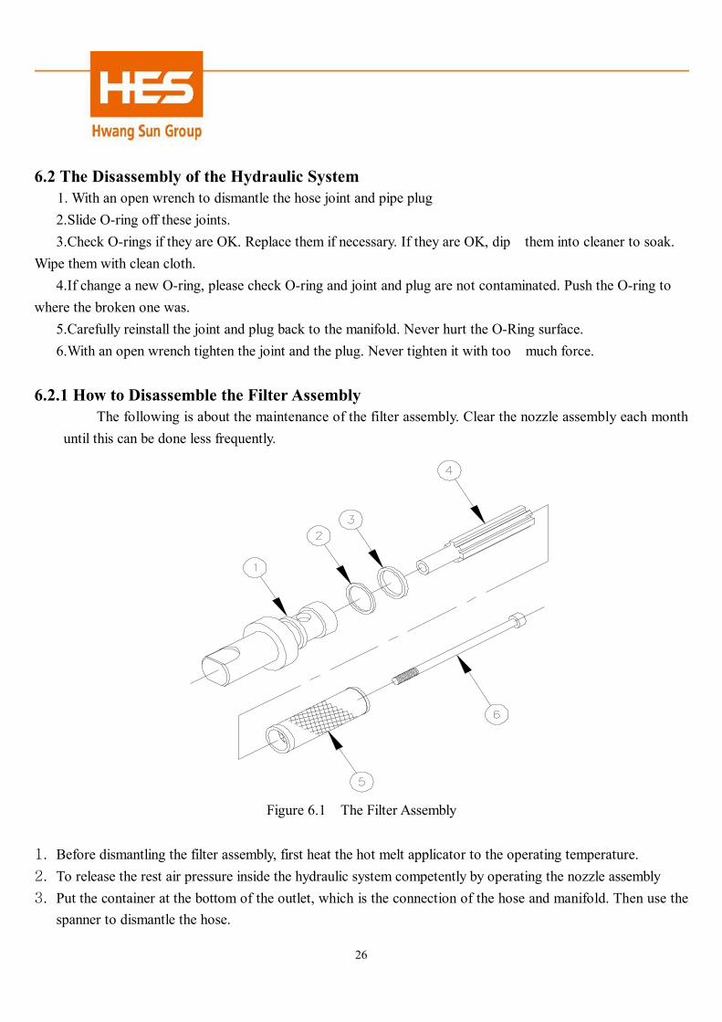
The following is about the maintenance of the filter assembly. Clear the nozzle assembly each month until this can be done less frequently.
Figure 6.1 The Filter Assembly
1. Before dismantling the filter assembly, first heat the hot melt applicator to the operating temperature. 2. To release the rest air pressure inside the hydraulic system competently by operating the nozzle assembly 3. Put the container at the bottom of the outlet, which is the connection of the hose and manifold. Then use the
spanner to dismantle the hose.
27
4. First adjust the air pressure to the operation status. Then start the cylinder pump to push the hot melt out of the manifold stably into the container. Do not stop the cylinder pump until all the impurities have been pushed out.
5. Use the spanner to dismantle the filter assembly. Pull the filter assembly out of the manifold vertically. 6. To dismantle the filter assembly, first dismantle the screw⑥, then separate the filter⑤ and the core④ in
order. Finally, slipping out the spacer③ and the O-ring② from the bolt①. 7. Check if every component, especially the filter⑤ and the O-ring②, is in good condition. Change a new one
if necessary. 8. If components are in good condition, dip them into the cleaning solvent. Some components need to be
heated by hot air gun or oven for easy clean. Use the brush (but not the metal one) to clean the filter if necessary. After cleaning, wipe all components with clean cloth.
9. Assemble the cleaned components and reinstall into the manifold. Use the spanner to lock the filter assembly tight. Pay attention to the force in order not to damage the O-ring and the screw threads of the manifold.
10. Adjust the air pressure to the operation status and start the cylinder pump. Do not stop the cylinder pump until the hot melt be pushed stably out of the manifold without impurities. Finally assemble the hose and nozzle assembly.
6.2.2 How to Disassemble the Pneumatic Pump
If no hot melt flows out for coating or hot melt flows unstable when operating the machine, there are many possible factors. One of them is that the O-ring inside the pump is ruined, resulting that hot melt cannot be sucked in or pumped out. Another factor is that the surface of the pneumatic pump is scratched, which leads to air leakage or unstable driving pressure (the latter indirectly affects the flow rate of hot melt).
The following is about how to disassemble and check the pneumatic pump. We suggest only qualified technicians do the job.

28
Figure 6.2 The Pneumatic Pump

29
1. Remove the shield of the pump, and then remove the two micro switches from the cylinder base. Note: Please get power supply disconnected before removing micro switch. 2. Heat the machine to normal operating temperature. When the hot melt in the melting tank is completely
melt, loosen the three hexagon bolts that fix the pneumatic pump on the melting tank. 3. Wear gloves and carefully take the pump out of the tank vertically. 4. Clean the pump with cloth. Disassemble the pump as the picture shows. 5. Vertically take the glue pipe (16) out of the washer (17). 6. Remove the tightening nut with adjustable spanner (13). 7. Take the steel ball (3) out of the tightening nut (1). 8. Open the cylinder (31) with an adjustable spanner. Carefully take the cylinder out along the cylinder
shaft (11). 9. Remove the fixing ring (9) with the adjustable spanner and take the steel ball (10) out of the cylinder shaft. 10. Loosen the bolts (35) that secure the cylinder with open-ended spanner, and then take out the four
bolts. 11. Remove the cylinder cover (35), and carefully take out the cylinder (31). Do not damage the
anti-leakage ring and the O-ring. 12. Loosen the nut (34) with open-ended spanner; gently remove the anti-leakage ring (28), the piston
plate (27) and the piston ring (24). 13. Loosen the anti-slip nut (23) and take the cylinder shaft (11) out of the cylinder (25) vertically. It is better
not to scratch the anti-leakage components. 14. Use the Hexagon spanner to remove the hexagon screw (13) that fix the connection base (18) on the
cylinder base . 15. Remove the anti-leakage components【includes (20),(22),(19)】and the tightening ring (21). 16. Remove all the O-rings from each component. This is the end of the disassembly. 17. Check if any component is damaged, especially whether the O-rings are aged. And check the cylinder
surface to see if any scratch on it. Change a new one if necessary. 18. If components are in good condition, dip them into the cleaning solvent. Some components need to be
heated by hot air gun or oven for easy clean. After cleaning, wipe all components with clean cloth. 19. Referring to the figure 6.2, reassemble the pump with good components (old or new) and reinstall it on the
applicator.

30
Chapter 7 Trouble Shooting 7.0 Introduction This chapter introduces how to prevent machinery trouble and the solution to the problems. This can make the machine life longer with higher efficiency. Please refer to Chapter 6 “Disassembly and Maintenance” when you needs detailed information for maintaining or replacing components. Some obvious problems, such as the broken of wire protection layer, should be noted during regular maintenance. 7.1 Safety Precautions
Get power supply disconnected when disassembling the control panel and the shield or replacing electric components. This can avoid staff injury and machine damage.
Do not try to disassemble the components of the manifold, hose and nozzle assembly. Discharge the pressure completely before disassembly. Otherwise, it may cause danger.
Always wear safety gloves, safety glasses and long sleeved uniform. Try to prevent your body from burnt by hot melt or hot component surface.
Do not heat the glued components with open flame or a blowtorch. Use electrical oven to heat or clean the components if necessary.
7.2Trouble Shoot on Mechanic & Electric Section
Problem Shooting Steps Or Causes Shooting Trouble Shoot 1.Main power is not completely ON or switch trouble.
Put power switch ON or the electric wire connection looses. Otherwise, replace with a new switch.
2. Temperature controller of tank dose not set at right temperature.
Readjust the temperature controller.
3.Mechanic Temperature Controller is set too low.
Reset the Mechanic Temperature Controller.
The Melting Tank Cannot be heated or the temperature does not reach the preset value
4. Heating bar at the bottom of tank or temperature controller is out of order.
Whether the wires are loosed. If not, replace heater or temperature controller with new ones.
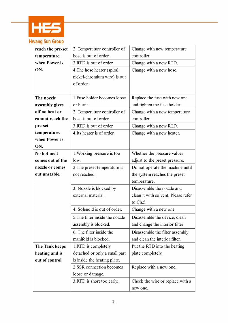
The hose has no heat or cannot
1.Fuse holder becomes loose or burned.
Replace the fuse with a new one and tighten the fuse holder.
31
2. Temperature controller of hose is out of order.
Change with new temperature controller.
3.RTD is out of order Change with a new RTD.
reach the pre-set temperature. when Power is ON. 4.The hose heater (spiral
nickel-chromium wire) is out of order.
Change with a new hose.
1.Fuse holder becomes loose or burnt.
Replace the fuse with new one and tighten the fuse holder.
2. Temperature controller of hose is out of order.
Change with a new temperature controller.
3.RTD is out of order Change with a new RTD.
The nozzle assembly gives off no heat or cannot reach the pre-set temperature. when Power is ON.
4.Its heater is of order. Change with a new heater.
1.Working pressure is too low.
Whether the pressure valves adjust to the preset pressure.
2.The preset temperature is not reached.
Do not operate the machine until the system reaches the preset temperature.
3. Nozzle is blocked by external material.
Disassemble the nozzle and clean it with solvent. Please refer to Ch.5.
4. Solenoid is out of order. Change with a new one.
5.The filter inside the nozzle assembly is blocked.
Disassemble the device, clean and change the interior filter
No hot melt comes out of the nozzle or comes out unstable.
6. The filter inside the manifold is blocked.
Disassemble the filter assembly and clean the interior filter.
1.RTD is completely detached or only a small part is inside the heating plate.
Put the RTD into the heating plate completely.
2.SSR connection becomes loose or damage.
Replace with a new one.
The Tank keeps heating and is out of control
3.RTD is short too early. Check the wire or replace with a new one.
32
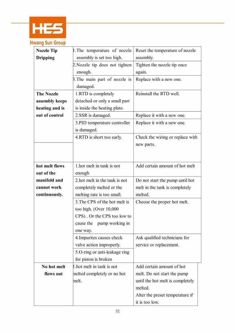
1. The temperature of nozzle assembly is set too high.
Reset the temperature of nozzle assembly.
2. Nozzle tip does not tighten enough.
Tighten the nozzle tip once again.
Nozzle Tip Dripping
3. The main part of nozzle is damaged.
Replace with a new one.
1.RTD is completely detached or only a small part is inside the heating plate.
Reinstall the RTD well.
2.SSR is damaged. Replace it with a new one. 3.PID temperature controller is damaged.
Replace it with a new one.
The Nozzle assembly keeps heating and is out of control
4.RTD is short too early. Check the wiring or replace with new parts.
1.hot melt in tank is not enough
Add certain amount of hot melt
2.hot melt in the tank is not completely melted or the melting rate is too small.
Do not start the pump until hot melt in the tank is completely melted.
3.The CPS of the hot melt is too high. (Over 10,000 CPS) . Or the CPS too low to cause the pump working in one way.
Choose the proper hot melt.
4.Impurites causes check valve action improperly.
hot melt flows out of the manifold and cannot work continuously.
5.O-ring or anti-leakage ring for piston is broken
Ask qualified technicians for service or replacement.
No hot melt flows out
1.hot melt in tank is not melted completely or no hot melt.
Add certain amount of hot melt. Do not start the pump until the hot melt is completely melted. Alter the preset temperature if it is too low.
33
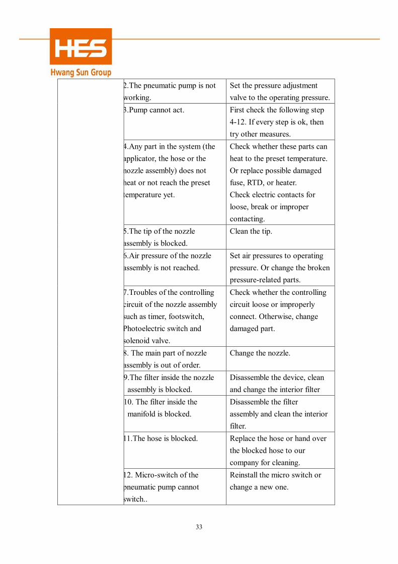
2.The pneumatic pump is not working.
Set the pressure adjustment valve to the operating pressure.
3.Pump cannot act. First check the following step 4-12. If every step is ok, then try other measures.
4.Any part in the system (the applicator, the hose or the nozzle assembly) does not heat or not reach the preset temperature yet.
Check whether these parts can heat to the preset temperature. Or replace possible damaged fuse, RTD, or heater. Check electric contacts for loose, break or improper contacting.
5.The tip of the nozzle assembly is blocked.
Clean the tip.
6.Air pressure of the nozzle assembly is not reached.
Set air pressures to operating pressure. Or change the broken pressure-related parts.
7.Troubles of the controlling circuit of the nozzle assembly such as timer, footswitch, Photoelectric switch and solenoid valve.
Check whether the controlling circuit loose or improperly connect. Otherwise, change damaged part.
8. The main part of nozzle assembly is out of order.
Change the nozzle.
9.The filter inside the nozzle assembly is blocked.
Disassemble the device, clean and change the interior filter
10. The filter inside the manifold is blocked.
Disassemble the filter assembly and clean the interior filter.
11.The hose is blocked. Replace the hose or hand over the blocked hose to our company for cleaning.
12. Micro-switch of the pneumatic pump cannot switch..
Reinstall the micro switch or change a new one.
34
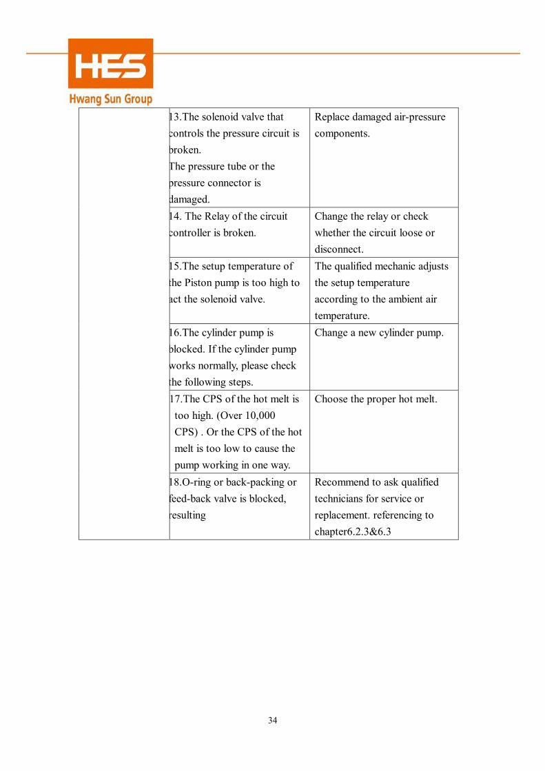
13.The solenoid valve that controls the pressure circuit is broken. The pressure tube or the pressure connector is damaged.
Replace damaged air-pressure components.
14. The Relay of the circuit controller is broken.
Change the relay or check whether the circuit loose or disconnect.
15.The setup temperature of the Piston pump is too high to act the solenoid valve.
The qualified mechanic adjusts the setup temperature according to the ambient air temperature.
16.The cylinder pump is blocked. If the cylinder pump works normally, please check the following steps.
Change a new cylinder pump.
17.The CPS of the hot melt is too high. (Over 10,000 CPS) . Or the CPS of the hot melt is too low to cause the pump working in one way.
Choose the proper hot melt.
18.O-ring or back-packing or feed-back valve is blocked, resulting
Recommend to ask qualified technicians for service or replacement. referencing to chapter6.2.3&6.3
35
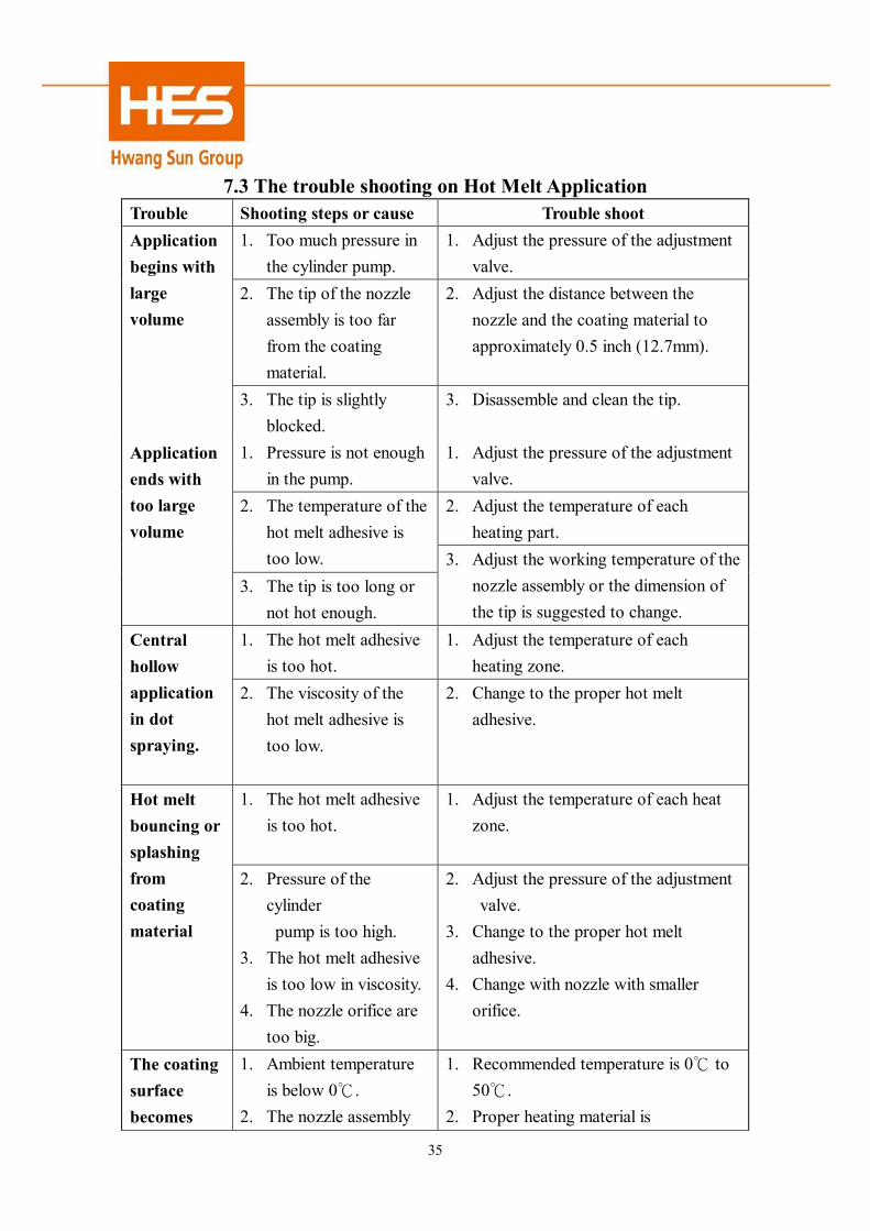
7.3 The trouble shooting on Hot Melt Application Trouble Shooting steps or cause Trouble shoot
1. Too much pressure in the cylinder pump.
1. Adjust the pressure of the adjustment valve.
2. The tip of the nozzle assembly is too far from the coating material.
2. Adjust the distance between the nozzle and the coating material to approximately 0.5 inch (12.7mm).
Application begins with large volume
3. The tip is slightly blocked.
3. Disassemble and clean the tip.
1. Pressure is not enough in the pump.
1. Adjust the pressure of the adjustment valve.
2. Adjust the temperature of each heating part.
2. The temperature of the hot melt adhesive is too low.
Application ends with too large volume
3. The tip is too long or not hot enough.
3. Adjust the working temperature of the nozzle assembly or the dimension of the tip is suggested to change.
1. The hot melt adhesive is too hot.
1. Adjust the temperature of each heating zone.
Central hollow application in dot spraying.
2. The viscosity of the hot melt adhesive is too low.
2. Change to the proper hot melt adhesive.
1. The hot melt adhesive is too hot.
1. Adjust the temperature of each heat zone.
Hot melt bouncing or splashing from coating material
2. Pressure of the cylinder
pump is too high. 3. The hot melt adhesive
is too low in viscosity. 4. The nozzle orifice are
too big.
2. Adjust the pressure of the adjustment valve.
3. Change to the proper hot melt adhesive.
4. Change with nozzle with smaller orifice.
The coating surface becomes
1. Ambient temperature is below 0℃.
2. The nozzle assembly
1. Recommended temperature is 0℃ to 50℃.
2. Proper heating material is
36
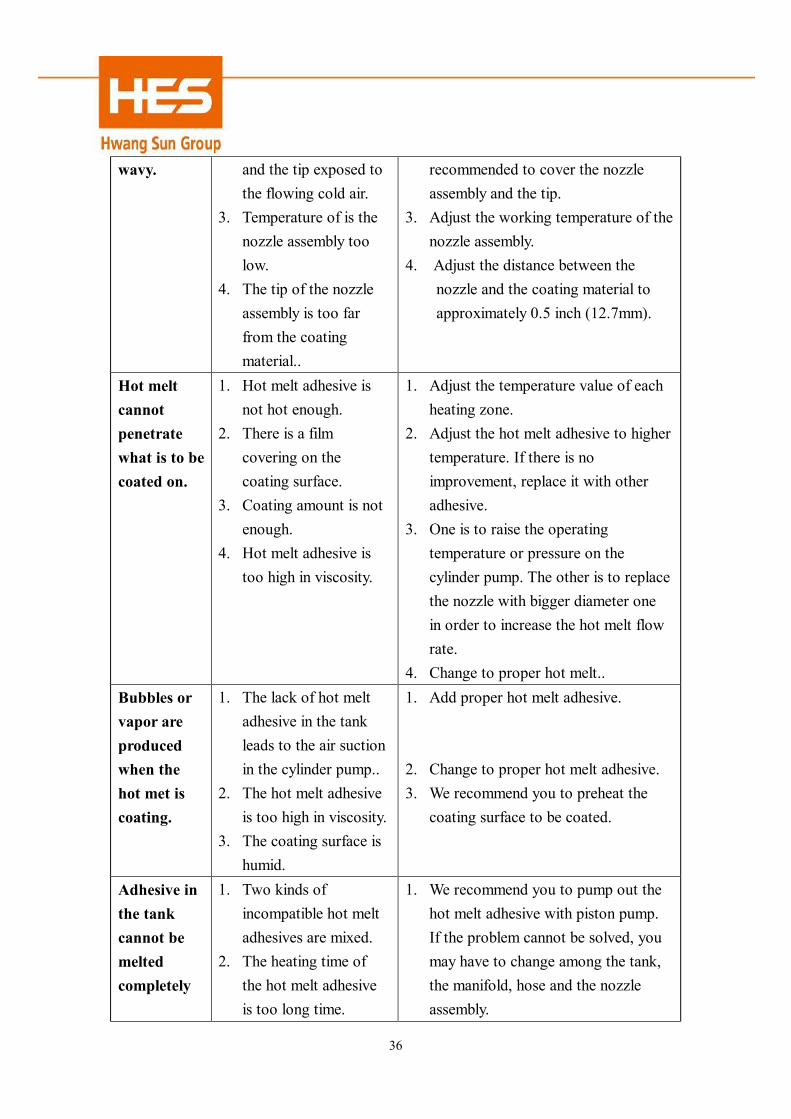
wavy. and the tip exposed to the flowing cold air.
3. Temperature of is the nozzle assembly too low.
4. The tip of the nozzle assembly is too far from the coating material..
recommended to cover the nozzle assembly and the tip.
3. Adjust the working temperature of the nozzle assembly.
4. Adjust the distance between the nozzle and the coating material to approximately 0.5 inch (12.7mm).
Hot melt cannot penetrate what is to be coated on.
1. Hot melt adhesive is not hot enough.
2. There is a film covering on the coating surface.
3. Coating amount is not enough.
4. Hot melt adhesive is too high in viscosity.
1. Adjust the temperature value of each heating zone.
2. Adjust the hot melt adhesive to higher temperature. If there is no improvement, replace it with other adhesive.
3. One is to raise the operating temperature or pressure on the cylinder pump. The other is to replace the nozzle with bigger diameter one in order to increase the hot melt flow rate.
4. Change to proper hot melt.. Bubbles or vapor are produced when the hot met is coating.
1. The lack of hot melt adhesive in the tank leads to the air suction in the cylinder pump..
2. The hot melt adhesive is too high in viscosity.
3. The coating surface is humid.
1. Add proper hot melt adhesive. 2. Change to proper hot melt adhesive. 3. We recommend you to preheat the
coating surface to be coated.
Adhesive in the tank cannot be melted completely
1. Two kinds of incompatible hot melt adhesives are mixed.
2. The heating time of the hot melt adhesive is too long time.
1. We recommend you to pump out the hot melt adhesive with piston pump. If the problem cannot be solved, you may have to change among the tank, the manifold, hose and the nozzle assembly.
37
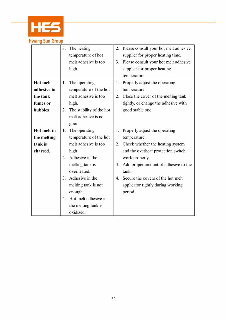
3. The heating temperature of hot melt adhesive is too high.
2. Please consult your hot melt adhesive supplier for proper heating time.
3. Please consult your hot melt adhesive supplier for proper heating temperature.
Hot melt adhesive in the tank fumes or bubbles
1. The operating temperature of the hot melt adhesive is too high.
2. The stability of the hot melt adhesive is not good.
1. Properly adjust the operating temperature.
2. Close the cover of the melting tank tightly, or change the adhesive with good stable one.
Hot melt in the melting tank is charred.
1. The operating temperature of the hot melt adhesive is too high
2. Adhesive in the melting tank is overheated.
3. Adhesive in the melting tank is not enough.
4. Hot melt adhesive in the melting tank is oxidized.
1. Properly adjust the operating temperature.
2. Check whether the heating system and the overheat protection switch work properly.
3. Add proper amount of adhesive to the tank.
4. Secure the covers of the hot melt applicator tightly during working period.

38
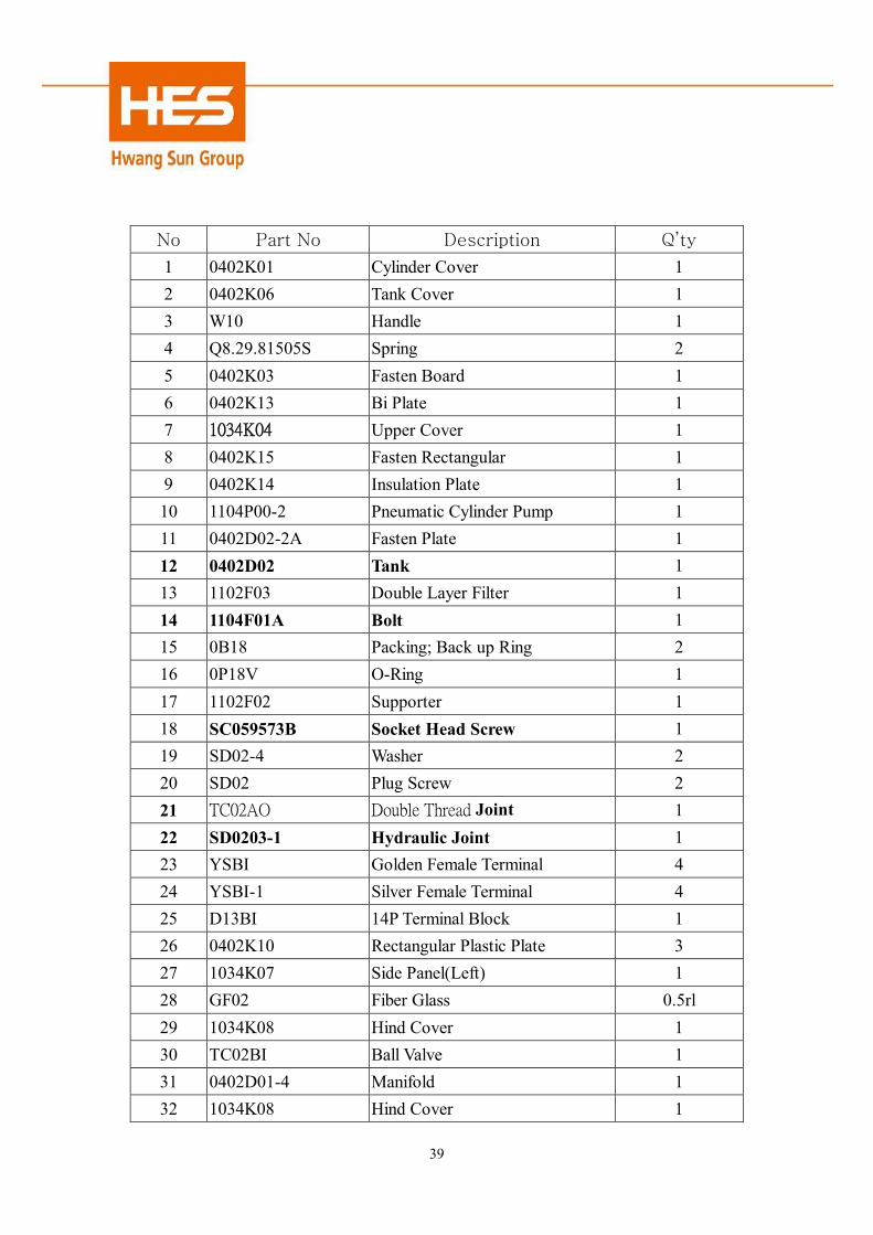
Chapter 8 Drawings of Spare Parts
8.1 Assembly Drawing of Metal Plates
39
No Part No Description Q’ty
1 0402K01 Cylinder Cover 1 2 0402K06 Tank Cover 1 3 W10 Handle 1 4 Q8.29.81505S Spring 2 5 0402K03 Fasten Board 1 6 0402K13 Bi Plate 1 7 1034K04 Upper Cover 1 8 0402K15 Fasten Rectangular 1 9 0402K14 Insulation Plate 1 10 1104P00-2 Pneumatic Cylinder Pump 1 11 0402D02-2A Fasten Plate 1 12 0402D02 Tank 1 13 1102F03 Double Layer Filter 1 14 1104F01A Bolt 1 15 0B18 Packing; Back up Ring 2 16 0P18V O-Ring 1 17 1102F02 Supporter 1 18 SC059573B Socket Head Screw 1 19 SD02-4 Washer 2 20 SD02 Plug Screw 2 21 TC02AO Double Thread Joint 1 22 SD0203-1 Hydraulic Joint 1 23 YSBI Golden Female Terminal 4 24 YSBI-1 Silver Female Terminal 4 25 D13BI 14P Terminal Block 1 26 0402K10 Rectangular Plastic Plate 3 27 1034K07 Side Panel(Left) 1 28 GF02 Fiber Glass 0.5rl 29 1034K08 Hind Cover 1 30 TC02BI Ball Valve 1 31 0402D01-4 Manifold 1 32 1034K08 Hind Cover 1

40
33 1104D04 Supporter(Short) 2 34 SP1/80683B Plug Screw 2 35 1104D05 Supporter(Long) 2 36 1034K09 Side Panel(Right) 1 37 0P20V O-Ring 1 38 1102H01 Narrow Valve Base 1 39 0G30V O-Ring 1 40 1104D06 Pressure Regulation Shaft 1 41 1104D07 Screw Nut 1 42 0402A17-2 Guide Funnel 1 43 1034K01 Control Box 1 44 0402K16 Fixing Base 1 45 1034K03 Cover Board 1

41
8.2 Assembly Drawing of Piston Pump
42
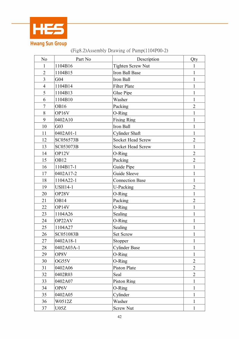
(Fig8.2)Assembly Drawing of Pump(1104P00-2)
No Part No Description Qty 1 1104B16 Tighten Screw Nut 1 2 1104B15 Iron Ball Base 1 3 G04 Iron Ball 1 4 1104B14 Filter Plate 1 5 1104B13 Glue Pipe 1 6 1104B10 Washer 1 7 OB16 Packing 2 8 OP16V O-Ring 1 9 0402A10 Fixing Ring 1
10 G03 Iron Ball 1 11 0402A01-1 Cylinder Shaft 1 12 SC056573B Socket Head Screw 2 13 SC053073B Socket Head Screw 1 14 OP12V O-Ring 2 15 OB12 Packing 2 16 1104B17-1 Guide Pipe 1 17 0402A17-2 Guide Sleeve 1 18 1104A22-1 Connection Base 1 19 USH14-1 U-Packing 2 20 OP28V O-Ring 1 21 OB14 Packing 2 22 OP14V O-Ring 1 23 1104A26 Sealing 1 24 OP22AV O-Ring 1 25 1104A27 Sealing 1 26 SC051083B Set Screw 1 27 0402A18-1 Stopper 1 28 0402A03A-1 Cylinder Base 1 29 OP8V O-Ring 1 30 OG55V O-Ring 2 31 0402A06 Piston Plate 2 32 0402R03 Seal 2 33 0402A07 Piston Ring 1 34 OP6V O-Ring 1 35 0402A05 Cylinder 1 36 W0512Z Washer 1 37 U05Z Screw Nut 1
43
38 0402A09 Hind cover of Cylinder 1 39 W0812Z Washer 4 40 SC0810063Z Socket Head Screw 4
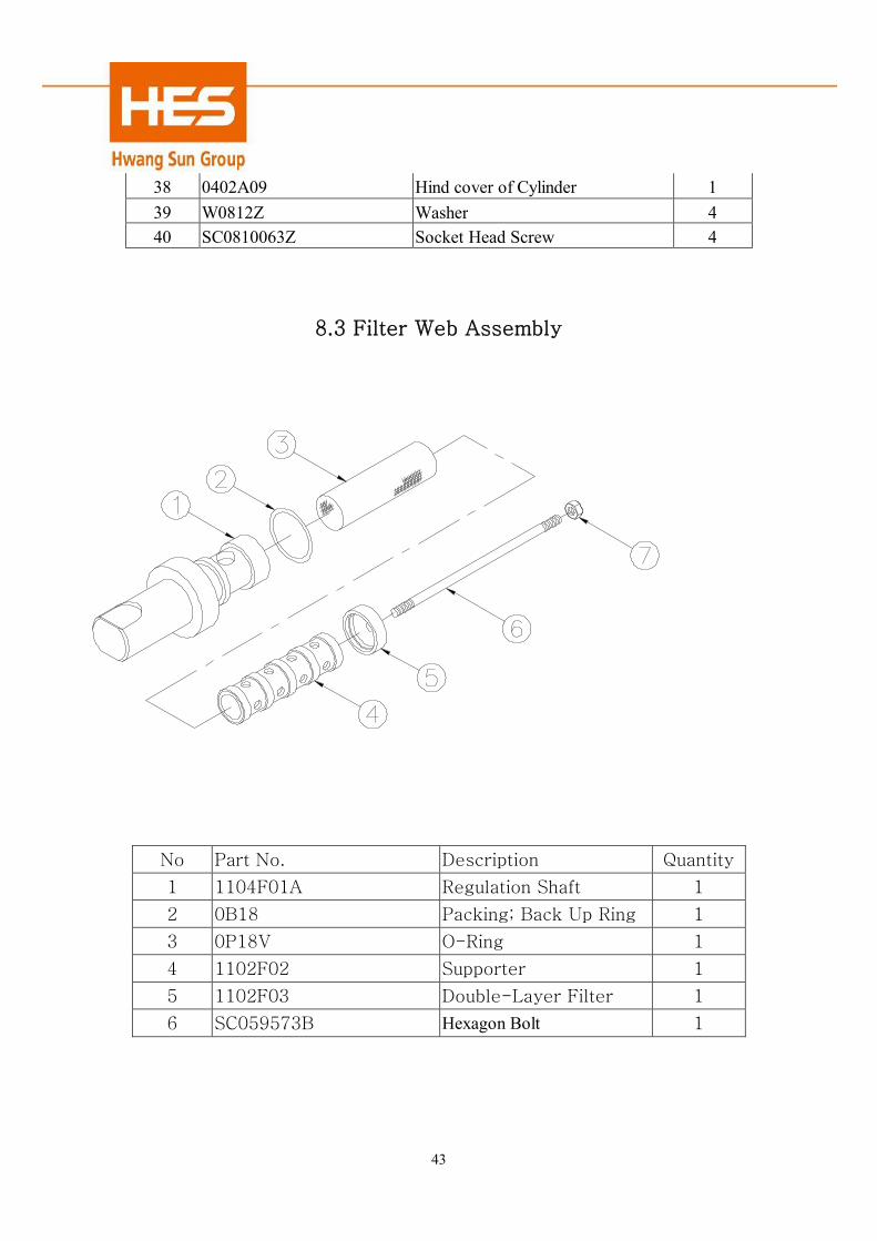
8.3 Filter Web Assembly
No Part No. Description Quantity
1 1104F01A Regulation Shaft 1
2 0B18 Packing; Back Up Ring 1
3 0P18V O-Ring 1
4 1102F02 Supporter 1
5 1102F03 Double-Layer Filter 1
6 SC059573B Hexagon Bolt 1
44
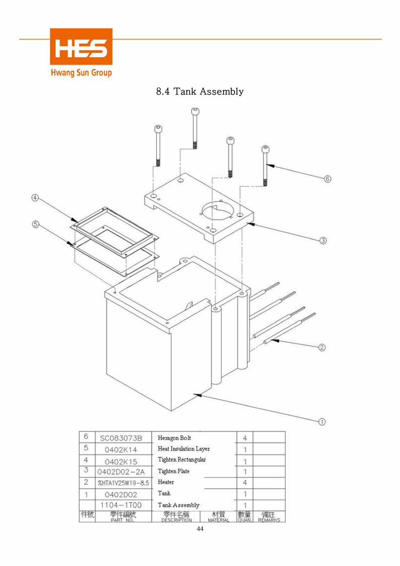
8.4 Tank Assembly

45
Chapter 9 Wiring Diagrams

46
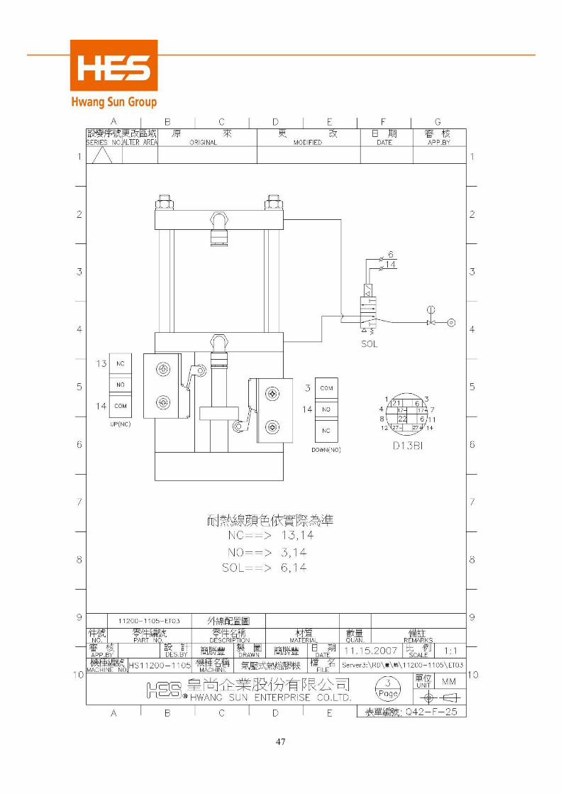
47

48