HRD DCI Series - Airwelllh.airwell-res.com/sites/default/files/product_uploads/Service... · D DCI...
59
HRD DCI Series Indoor Units Outdoor Units AWSI-HRD009-N91 7SP023060 AWAU-YRD009-H91 7SP062915 AWSI-HRD012-N91 7SP023061 AWAU-YRD012-H91 7SP062916 REFRIGERANT R32 HEATPUMP REFRIGERANT SM HRD DCI 1 GB MAY-2017
-
Upload
trinhquynh -
Category
Documents
-
view
216 -
download
0
Transcript of HRD DCI Series - Airwelllh.airwell-res.com/sites/default/files/product_uploads/Service... · D DCI...

HRD DCI Series
Indoor Units Outdoor Units
AWSI-HRD009-N91 7SP023060 AWAU-YRD009-H91 7SP062915
AWSI-HRD012-N91 7SP023061
AWAU-YRD012-H91 7SP062916
REFRIGERANT
R32 HEATPUMP
REFRIGERANT
SM HRD DCI 1 GB MAY-2017

CONTENTS 1. Precaution ................................................................................................................................................. 1
1.1 Safety Precaution ..................................................................................................................... 1
1.2 Warning .................................................................................................................................... 1
2. Information servicing ............................................................................................................................... 4
3. Specification ............................................................................................................................................. 8
4. Dimension ............................................................................................................................................... 10
4.1 Indoor Unit .............................................................................................................................. 10
4.2 Outdoor Unit ........................................................................................................................... 12
5. Refrigerant Cycle Diagram .................................................................................................................... 13
6. Installation Details .................................................................................................................................. 14
6.1 Wrench torque sheet for installation ...................................................................................... 14
6.2 Connecting the cables............................................................................................................ 14
6.3 Pipe length and the elevation ................................................................................................. 15
6.4 Installation for the first time .................................................................................................... 16
6.5 Adding the refrigerant after running the system for many years ........................................... 17
6.6 Re-installation while the indoor unit need to be repaired ....................................................... 17
6.7 Re-installation while the outdoor unit need to be repaired .................................................... 18
7. Operation Characteristics ..................................................................................................................... 20
8. Wiring Diagram ....................................................................................................................................... 21
8.1 Indoor Unit:9K/12K .............................................................................................................. 21
8.2 Outdoor Unit: 9K/12K ............................................................................................................. 22
9. Electronic function ................................................................................................................................. 23
9.1 Abbreviation ........................................................................................................................... 23
9.2 Display function ...................................................................................................................... 23
9.3 Main Protection ...................................................................................................................... 23
9.4 Operation Modes and Functions ............................................................................................ 24
10. Troubleshooting .................................................................................................................................... 31
10.1 Indoor Unit Error Display ........................................................................................................ 32
10.2 Trouble shooting ..................................................................................................................... 33
11. Exploded view and spare part list ........................................................................................................ 51
Caution: Risk of fire/flammable material
PREC AUTION
HRD DCI 1 Version - 1
1. Precaution
1.1 Safety Precaution
To prevent injury to the user or other
people and property damage, the following
instructions must be followed.
Incorrect operation due to ignoring
instruction will cause harm or damage.
Before service the unit, be sure to
read this service manual at first.
1.2 Warning
Installation
Do not use a defective or underrated
circuit breaker. Use this appliance on a
dedicated circuit.
There is risk of fire or electric shock.
For electrical work, contact the dealer,
seller, a qualified electrician, or an
authorized service center.
Do not disassemble or repair the product,
there is risk of fire or electric shock.
Always ground the product.
There is risk of fire or electric shock.
Install the panel and the cover of
control box securely.
There is risk of fire of electric shock.
Always install a dedicated circuit and
breaker.
Improper wiring or installation may cause fore
or electric shock.
Use the correctly rated breaker of
fuse.
There is risk of fire or electric shock.
Do not modify or extend the power
cable.
There is risk of fire or electric shock.
Do not install, remove, or reinstall the
unit by yourself (customer).
There is risk of fire, electric shock, explosion,
or injury.
Be caution when unpacking and
installing the product.
Sharp edges could cause injury, be especially
careful of the case edges and the fins on the
condenser and evaporator.
For installation, always contact the
dealer or an authorized service center.
Do not install the product on a
defective installation stand.
Be sure the installation area does not
deteriorate with age.
If the base collapses, the air conditioner could
fall with it, causing property damage, product
failure, and personal injury.
Do not let the air conditioner run for a
long time when the humidity is very high
and a door or a window is left open.
Take care to ensure that power cable
could not be pulled out or damaged during
operation.
There is risk of fire or electric shock.
Do not place anything on the power
cable.
There is risk of fire or electric shock.
Do not plug or unplug the power
supply plug during operation.
There is risk of fire or electric shock.
Do not touch (operation) the product
with wet hands.
Do not place a heater or other
appliance near the power cable.
There is risk of fire and electric shock.
Do not allow water to run into
electrical parts.
It may cause fire, failure of the product, or
electric shock.
Do not store or use flammable gas or
combustible near the product.
There is risk of fire or failure of product.
Do not use the product in a tightly
closed space for a long time.
Oxygen deficiency could occur.
When flammable gas leaks, turn off
the gas and open a window for ventilation
before turn the product on.
If strange sounds or smoke comes
from product, turn the breaker off or
disconnect the power supply cable.

PRECAUTION
Version - 1 2 HRD DCI
There is risk of electric shock or fire.
Stop operation and close the window
in storm or hurricane. If possible, remove
the product from the window before the
hurricane arrives.
There is risk of property damage, failure of
product, or electric shock.
Do not open the inlet grill of the
product during operation. (Do not touch the
electrostatic filter, if the unit is so equipped.)
There is risk of physical injury, electric shock,
or product failure.
When the product is soaked, contact
an authorized service center.
There is risk of fire or electric shock.
Be caution that water could not enter
the product.
There is risk of fire, electric shock, or product
damage.
Ventilate the product from time to
time when operating it together with a stove
etc.
There is risk of fire or electric shock.
Turn the main power off when
cleaning or maintaining the product.
There is risk of electric shock.
When the product is not be used for a
long time, disconnect the power supply plug
or turn off the breaker.
There is risk of product damage or failure, or
unintended operation.
Take care to ensure that nobody
could step on or fall onto the outdoor unit.
This could result in personal injury and
product damage.
CAUTION
Always check for gas (refrigerant)
leakage after installation or repair of
product.
Low refrigerant levels may cause failure of
product.
Install the drain hose to ensure that
water is drained away properly.
A bad connection may cause water leakage.
Keep level even when installing the
product.
It can avoid vibration of water leakage.
Do not install the product where the
noise or hot air from the outdoor unit could
damage the neighborhoods.
It may cause a problem for your neighbors.
Use two or more people to lift and
transport the product.
Do not install the product where it will
be exposed to sea wind (salt spray) directly.
It may cause corrosion on the product.
Corrosion, particularly on the condenser and
evaporator fins, could cause product
malfunction or inefficient operation.
Operational
Do not expose the skin directly to
cool air for long time. (Do not sit in the
draft).
Do not use the product for special
purposes, such as preserving foods, works
of art etc. It is a consumer air conditioner,
not a precision refrigerant system.
There is risk of damage or loss of property.
Do not block the inlet or outlet of air
flow.
Use a soft cloth to clean. Do not use
harsh detergents, solvents, etc.
There is risk of fire, electric shock, or damage
to the plastic parts of the product.
Do not touch the metal parts of the
product when removing the air filter. They
are very sharp.
Do not step on or put anything on the
product. (outdoor units)
Always insert the filter securely.
Clean the filter every two weeks or more
often if necessary.
A dirty filter reduces the efficiency of the air
conditioner and could cause product
malfunction or damage.
Do not insert hands or other objects
through air inlet or outlet while the product
is operated.

PREC AUTION
HRD DCI 3 Version - 1
Do not drink the water drained from
the product.
Use a firm stool or ladder when
cleaning or maintaining the product.
Be careful and avoid personal injury.
Replace the all batteries in the remote
control with new ones of the same type. Do
not mix old and new batteries or different
types of batteries.
There is risk of fire or explosion.
Do not recharge or disassemble the
batteries. Do not dispose of batteries in a
fire.
They may burn of explode.
If the liquid from the batteries gets
onto your skin or clothes, wash it well with
clean water. Do not use the remote of the
batteries have leaked.

INFORMATION SERVICING
Version - 1 4 HRD DCI
2. Information servicing
2.1 Checks to the area
Prior to beginning work on systems containing
flammable refrigerants, safety checks are
necessary to ensure that the risk of ignition is
minimised. For repair to the refrigerating
system, the following precautions shall be
complied with prior to conducting work on the
system.
2.2 Work procedure
Work shall be undertaken under a controlled
procedure so as to minimise the risk of a
flammable gas or vapour being present while
the work is being performed.
2.3 General work area
All maintenance staff and others working in the
local area shall be instructed on the nature
of work being carried out. Work in confined
spaces shall be avoided. The area around the
work space shall be sectioned off. Ensure that
the conditions within the area have been
made safe by control of flammable material.
2.4 Checking for presence of refrigerant
The area shall be checked with an appropriate
refrigerant detector prior to and during work,
to ensure the technician is aware of potentially
flammable atmospheres. Ensure that the
leak detection equipment being used is suitable
for use with flammable refrigerants, i.e. no
sparking, adequately sealed or intrinsically
safe.
2.5 Presence of fire extinguisher
If any hot work is to be conducted on the
refrigeration equipment or any associated parts,
appropriate fire extinguishing equipment shall
be available to hand. Have a dry powder or
CO2 fire extinguisher adjacent to the charging
area.
2.6 No ignition sources
No person carrying out work in relation to a
refrigeration system which involves exposing
any pipe work that contains or has contained
flammable refrigerant shall use any sources of
ignition in such a manner that it may lead to the
risk of fire or explosion. All possible ignition
sources, including cigarette smoking, should be
kept sufficiently far away from the site of
installation, repairing, removing and disposal,
during which flammable refrigerant can
possibly be released to the surrounding space.
Prior to work taking place, the area around
the equipment is to be surveyed to make sure
that there are no flammable hazards or ignition
risks.NO SMOKING signs shall be displayed.
2.7 Ventilated area
Ensure that the area is in the open or that it is
adequately ventilated before breaking into the
system or conducting any hot work. A degree of
ventilation shall continue during the period
that the work is carried out. The ventilation
should safely disperse any released refrigerant
and preferably expel it externally into the
atmosphere.
2.8 Checks to the refrigeration equipment
Where electrical components are being
changed, they shall be fit for the purpose and to
the correct specification. At all times the
manufacturer's maintenance and service
guidelines shall be followed. If in doubt consult
the manufacturer's technical department for
assistance. The following checks shall be
applied to installations using flammable
refrigerants:
the charge size is in accordance with the
room size within which the refrigerant
containing parts are installed;
the ventilation machinery and outlets are
operating adequately and are not obstructed;
if an indirect refrigerating circuit is being
used, the secondary circuit shall be checked
for the presence of refrigerant; marking to the
equipment continues to be visible and legible.
markings and signs that are illegible shall be
corrected;
refrigeration pipe or components are
installed in a position where they are unlikely to
be exposed to any substance which may
corrode refrigerant containing components,
unless the components are constructed of

INFORMATION SERVICING
HRD DCI 5 Version - 1
materials which are inherently resistant to being
corroded or are suitably protected against being
so corroded.
2.9 Checks to electrical devices
Repair and maintenance to electrical
components shall include initial safety checks
and component inspection procedures. If a fault
exists that could compromise safety, then no
electrical supply shall be connected to the
circuit until it is satisfactorily dealt with. If the
fault cannot be corrected immediately but it is
necessary to continue operation, an adequate
temporary solution shall be used. This shall be
reported to the owner of the equipment so all
parties are advised. Initial safety checks shall
include:
that capacitors are discharged: this shall be
done in a safe manner to avoid possibility of
sparking;
that there no live electrical components and
wiring are exposed while charging, recovering
or purging the system;
that there is continuity of earth bonding.
2.10 Repairs to sealed components
2.10.1 During repairs to sealed components,
all electrical supplies shall be disconnected
from the equipment being worked upon prior to
any removal of sealed covers, etc. If it is
absolutely necessary to have an electrical
supply to equipment during servicing, then a
permanently operating form of leak detection
shall be located at the most critical point to
warn of a potentially hazardous situation.
2.10.2 Particular attention shall be paid to the
following to ensure that by working on electrical
components, the casing is not altered in such a
way that the level of protection is affected. This
shall include damage to cables, excessive
number of connections, terminals not made to
original specification, damage to seals,
incorrect fitting of glands, etc.
Ensure that apparatus is mounted securely.
Ensure that seals or sealing materials have
not degraded such that they no longer serve
the purpose of preventing the ingress of
flammable atmospheres. Replacement parts
shall be in accordance with the manufacturer's
specifications.
NOTE: The use of silicon sealant may inhibit
the effectiveness of some types of leak
detection equipment. Intrinsically safe
components do not have to be isolated prior to
working on them.
2.11 Repair to intrinsically safe components
Do not apply any permanent inductive or
capacitance loads to the circuit without
ensuring that this will not exceed the
permissible voltage and current permitted for
the equipment in use. Intrinsically safe
components are the only types that can be
worked on while live in the presence of a
flammable atmosphere. The test apparatus
shall be at the correct rating.
Replace components only with parts specified
by the manufacturer. Other parts may result
in the ignition of refrigerant in the atmosphere
from a leak.
2.12 Cabling
Check that cabling will not be subject to wear,
corrosion, excessive pressure, vibration, sharp
edges or any other adverse environmental
effects. The check shall also take into account
the effects of aging or continual vibration from
sources such as compressors or fans.
2.13 Detection of flammable refrigerants
Under no circumstances shall potential sources
of ignition be used in the searching for or
detection of refrigerant leaks. A halide torch (or
any other detector using a naked flame)
shall not be used.
2.14 Leak detection methods
The following leak detection methods are
deemed acceptable for systems containing
flammable refrigerants. Electronic leak
detectors shall be used to detect flammable
refrigerants, but the sensitivity may not be
adequate, or may need re-calibration.
(Detection equipment shall be calibrated in a
refrigerant-free area.) Ensure that the detector
is not a potential source of ignition and is

INFORMATION SERVICING
Version - 1 6 HRD DCI
suitable for the refrigerant used. Leak detection
equipment shall be set at a percentage of the
LFL of the refrigerant and shall be calibrated to
the refrigerant employed and the appropriate
percentage of gas (25 % maximum) is
confirmed. Leak detection fluids are suitable for
use with most refrigerants but the use of
detergents containing chlorine shall be avoided
as the chlorine may react with the refrigerant
and corrode the copper pipe-work.
If a leak is suspected, all naked flames shall
be removed or extinguished.
If a leakage of refrigerant is found which
requires brazing, all of the refrigerant shall be
recovered from the system, or isolated (by
means of shut off valves) in a part of the
system
remote from the leak. Oxygen free nitrogen
(OFN) shall then be purged through the
system both before and during the brazing
process.
2.15 Removal and evacuation
When breaking into the refrigerant circuit to
make repairs or for any other purpose
conventional procedures shall be used.
However, it is important that best practice is
followed since flammability is a consideration.
The following procedure shall be adhered to:
remove refrigerant;
purge the circuit with inert gas;
evacuate;
purge again with inert gas;
open the circuit by cutting or brazing.
The refrigerant charge shall be recovered into
the correct recovery cylinders. The system
shall be flushed with OFN to render the
unit safe. This process may need to be
repeated several times. Compressed air or
oxygen shall not be used for this task. Flushing
shall be achieved by breaking the vacuum in
the system with OFN and continuing to fill until
the working pressure is achieved, then venting
to atmosphere, and finally pulling down to a
vacuum. This process shall be repeated until no
refrigerant is within the system. When the final
OFN charge is used, the system shall be
vented down to atmospheric pressure to enable
work to take place. This operation is absolutely
vital if brazing operations on the pipe-work are
to take place.
Ensure that the outlet for the vacuum pump is
not close to any ignition sources and there is
ventilation available.
2.16 16. Charging procedures
In addition to conventional charging procedures,
the following requirements shall be followed:
Ensure that contamination of different
refrigerants does not occur when using
charging equipment. Hoses or lines shall be as
short as possible to minimize the amount of
refrigerant contained in them.
Cylinders shall be kept upright.
Ensure that the refrigeration system is
earthed prior to charging the system with
refrigerant.
Label the system when charging is complete
(if not already).
Extreme care shall be taken not to overfill
the refrigeration system.
Prior to recharging the system it shall be
pressure tested with OFN. The system shall be
leak tested on completion of charging but prior
to commissioning. A follow up leak test shall be
carried out prior to leaving the site.
2.17 Decommissioning
Before carrying out this procedure, it is
essential that the technician is completely
familiar with the equipment and all its detail. It is
recommended good practice that all
refrigerants are recovered safely. Prior to the
task being carried out, an oil and refrigerant
sample shall be taken.
In case analysis is required prior to re-use of
reclaimed refrigerant. It is essential that
electrical power is available before the task is
commenced.
a) Become familiar with the equipment and its
operation.
b) Isolate system electrically.
c) Before attempting the procedure ensure that:

INFORMATION SERVICING
HRD DCI 7 Version - 1
mechanical handling equipment is available,
if required, for handling refrigerant cylinders;
all personal protective equipment is
available and being used correctly;
the recovery process is supervised at all
times by a competent person;
recovery equipment and cylinders conform
to the appropriate standards.
d) Pump down refrigerant system, if possible.
e) If a vacuum is not possible, make a manifold
so that refrigerant can be removed from various
parts of the system.
f) Make sure that cylinder is situated on the
scales before recovery takes place.
g) Start the recovery machine and operate in
accordance with manufacturer's instructions.
h) Do not overfill cylinders. (No more than 80 %
volume liquid charge).
i) Do not exceed the maximum working
pressure of the cylinder, even temporarily.
j) When the cylinders have been filled correctly
and the process completed, make sure that
the cylinders and the equipment are removed
from site promptly and all isolation valves on
the equipment are closed off.
k) Recovered refrigerant shall not be charged
into another refrigeration system unless it has
been cleaned and checked.
2.18 Labelling
Equipment shall be labelled stating that it has
been de-commissioned and emptied of
refrigerant. The label shall be dated and signed.
Ensure that there are labels on the equipment
stating the equipment contains flammable
refrigerant.
2.19 Recovery
When removing refrigerant from a system,
either for servicing or decommissioning, it is
recommended good practice that all
refrigerants are removed safely.
When transferring refrigerant into cylinders,
ensure that only appropriate refrigerant
recovery cylinders are employed. Ensure that
the correct numbers of cylinders for holding the
total system charge are available. All cylinders
to be used are designated for the recovered
refrigerant and labelled for that refrigerant (i.e.
special cylinders for the recovery of refrigerant).
Cylinders shall be complete with pressure relief
valve and associated shut-off valves in good
working order.
Empty recovery cylinders are evacuated
and, if possible, cooled before recovery occurs.
The recovery equipment shall be in good
working order with a set of instructions
concerning the equipment that is at hand and
shall be suitable for the recovery of flammable
refrigerants. In addition, a set of calibrated
weighing scales shall be available and in good
working order.
Hoses shall be complete with leak-free
disconnect couplings and in good condition.
Before using the recovery machine, check that
it is in satisfactory working order, has been
properly maintained and that any associated
electrical components are sealed to prevent
ignition in the event of a refrigerant release.
Consult manufacturer if in doubt.
The recovered refrigerant shall be returned
to the refrigerant supplier in the correct
recovery cylinder, and the relevant Waste
Transfer Note arranged. Do not mix refrigerants
in recovery units and especially not in cylinders.
If compressors or compressor oils are to be
removed, ensure that they have been
evacuated to an acceptable level to make
certain that flammable refrigerant does not
remain within the lubricant. The evacuation
process shall be carried out prior to returning
the compressor to the suppliers. Only electric
heating to the compressor body shall be
employed to accelerate this process. When oil
is drained from a system, it shall be carried
out safely.

SPECIFICATION
Version - 1 8 HRD DCI
3. Specification
Model: AWSI-HRD009-N91 / AWAU-YRD009-H91
MODEL INDOOR UNIT AWSI-HRD009-N91
Model Outdoor Unit AWAU-YRD009-H91
Installation Method of Pipe Flared
Characteristics Units Cooling Heating
Average Warm Cold
Capacity (1) kW 2.65(1.0-4.7) 4.1(0.9-5.2)
Pdesign kW 2.65 2.3 3 3.6
SEER /SCOP (2) W/W 9.3 5.1 6.1 4.0
Energy efficiency class A+++ A+++ A+++ A+
Annual energy consumption kWh 100 632 689 1890
Tbiv oC N/A -7 2 -15
Tol oC N/A -30
Power supply V/Ph/Hz 220-240V/Single/50Hz
Circuit breaker rating A 10
IND
OO
R
Fan type & quantity Cross flow fan x1
Fan speeds VL/L/M/H RPM
Air flow (3) VL/L/M/H m3/hr 260/400/470/850
External static pressure Min-Max Pa 0
Sound power level (4) H dB(A) 59
Sound pressure level(5) VL/L/M/H dB(A) 20/28/32/39
Moisture removal l/hr 1
Condensate drain tube I.D mm 16
Dimensions WxHxD mm 895x298x248
Weight kg 13
Package dimensions LxWxH mm 975x325x370
Packaged weight kg 17
Stacking height units 8
OU
TD
OO
R
Refrigerant control EEV
Compressor type, model Rotary DC Inverter
Fan type & quantity Axial x 1
Fan speeds H RPM
Air flow H m3/hr 1980
Sound power level(4) H dB(A) 57
Sound pressure level(5) H dB(A) 51
Dimensions WxHxD mm 800x554x333
Weight kg 36.4
Package dimensions LxWxH mm 900x615x390
Packaged weight kg 39.7
Stacking height Units 4
Refrigerant type R32
Refrigerant charge (standard connecting tubing length) kg(5m) 0.87
Additional charge per 1 meter gr / 1m 15
Connections between units Liquid line In.(mm) 1/4’’(6.35mm)
Suction line In.(mm) 3/8’’(9.53mm)
Max.tubing length m. 25
Max.height difference m. 10
Operation control type Remote control RC08C
Heating elements kW -
Others -
SPECIFICATION
HRD DCI 9 Version - 1
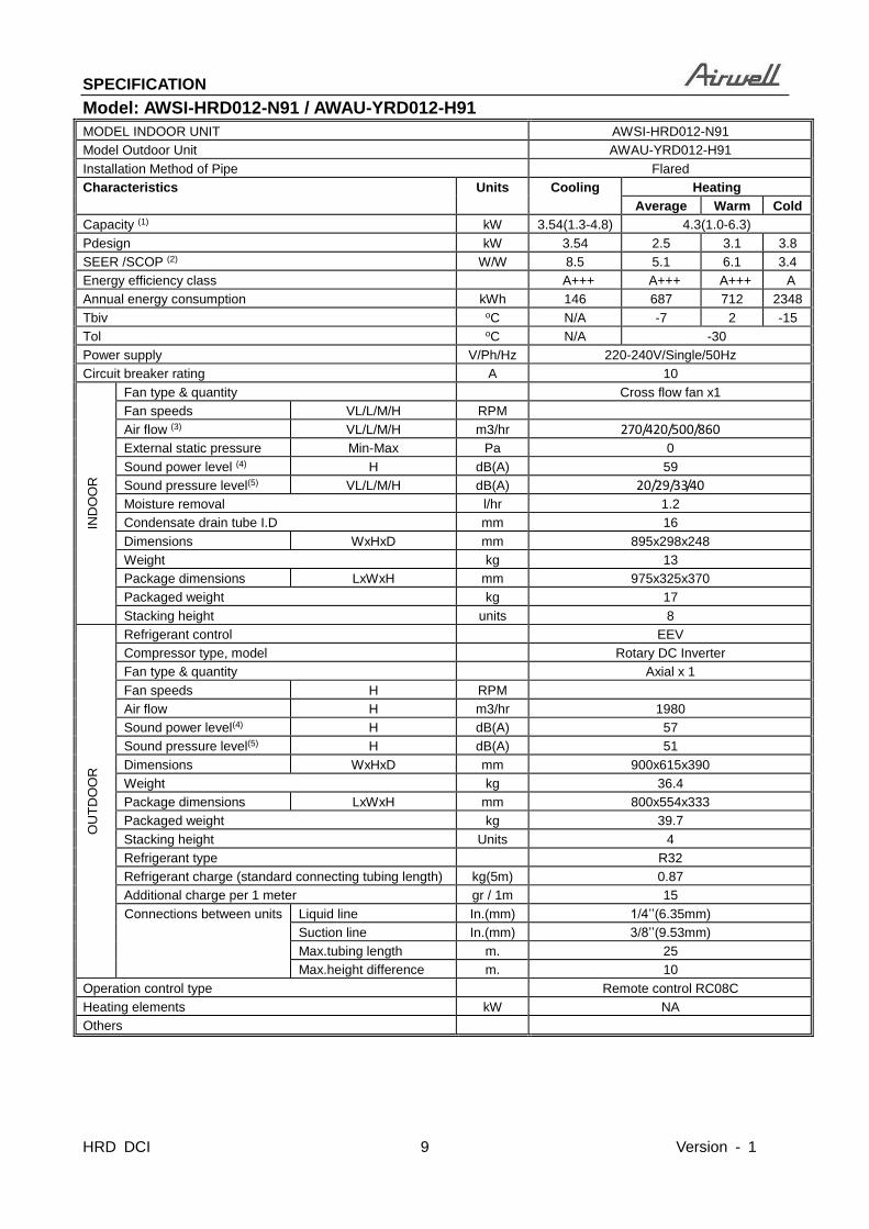
Model: AWSI-HRD012-N91 / AWAU-YRD012-H91
MODEL INDOOR UNIT AWSI-HRD012-N91
Model Outdoor Unit AWAU-YRD012-H91
Installation Method of Pipe Flared
Characteristics Units Cooling Heating
Average Warm Cold
Capacity (1) kW 3.54(1.3-4.8) 4.3(1.0-6.3)
Pdesign kW 3.54 2.5 3.1 3.8
SEER /SCOP (2) W/W 8.5 5.1 6.1 3.4
Energy efficiency class A+++ A+++ A+++ A
Annual energy consumption kWh 146 687 712 2348
Tbiv oC N/A -7 2 -15
Tol oC N/A -30
Power supply V/Ph/Hz 220-240V/Single/50Hz
Circuit breaker rating A 10
IND
OO
R
Fan type & quantity Cross flow fan x1
Fan speeds VL/L/M/H RPM
Air flow (3) VL/L/M/H m3/hr 270/420/500/860
External static pressure Min-Max Pa 0
Sound power level (4) H dB(A) 59
Sound pressure level(5) VL/L/M/H dB(A) 20/29/33/40
Moisture removal l/hr 1.2
Condensate drain tube I.D mm 16
Dimensions WxHxD mm 895x298x248
Weight kg 13
Package dimensions LxWxH mm 975x325x370
Packaged weight kg 17
Stacking height units 8
OU
TD
OO
R
Refrigerant control EEV
Compressor type, model Rotary DC Inverter
Fan type & quantity Axial x 1
Fan speeds H RPM
Air flow H m3/hr 1980
Sound power level(4) H dB(A) 57
Sound pressure level(5) H dB(A) 51
Dimensions WxHxD mm 900x615x390
Weight kg 36.4
Package dimensions LxWxH mm 800x554x333
Packaged weight kg 39.7
Stacking height Units 4
Refrigerant type R32
Refrigerant charge (standard connecting tubing length) kg(5m) 0.87
Additional charge per 1 meter gr / 1m 15
Connections between units Liquid line In.(mm) 1/4’’(6.35mm)
Suction line In.(mm) 3/8’’(9.53mm)
Max.tubing length m. 25
Max.height difference m. 10
Operation control type Remote control RC08C
Heating elements kW NA
Others

D I M E N S I O N
Version - 1 10 HRD DCI
4. Dimension
4.1 Indoor Unit
Model W D H
9K 895 248 298
12K 895 248 298

D I M E N S I O N
HRD DCI 11 Version - 1

D I M E N S I O N
Version - 1 12 HRD DCI
4.2 Outdoor Unit
More than 30cm
More than 60cm
More than 200cm
More than 30cm
More than 60cm
(Service space)
Fence orobstacles
For 9K/12K
800 W
514 W1
554
60
85.5
340
12.0
311
815 W3
365
333 D
70 W2
H
H1
H2
D1
D2 D3
62 B1
106
B2
20 A1R20
R6
61.6 A2

REFRIGERANT CYCLE DI AGRAM
HRD DCI 13 Version - 1
5. Refrigerant Cycle Diagram
LIQUID SIDE
GAS SIDE
HEAT
EXCHANGE
(EVAPORATOR)
HEAT
EXCHANGE
(CONDENSER)
Compressor
2-WAY VALVE
3-WAY VALVE
4-WAY VALVE
COOLING
HEATING
T2B Evaporator
temp. sensor
outlet
T1 Room temp.
sensor
T3 Condenser
temp. sensor
T5 Discharge
temp. sensor
T4 Ambient
temp. sensor
INDOOR OUTDOOR
T2 Evaporator
temp. sensor
middle
Accumulator
Electronic
expansion valveCAPILIARY TUBE

I N S TAL L AT I O N D E TAI L S
Version - 1 14 HRD DCI
6. Installation Details
6.1 Wrench torque sheet for installation
Outside diameter Torque Additional tightening torque
mm inch N.cm N.cm
Ф6.35 1/4 1500(153kgf.cm) 1600(163kgf.cm)
Ф9.52 3/8 2500(255kgf.cm) 2600(265kgf.cm)
Ф12.7 1/2 3500(357kgf.cm) 3600(367kgf.cm)
Ф15.9 5/8 4500(459kgf.cm) 4700(479kgf.cm)
Ф19 3/4 6500(663kgf.cm) 6700(683kgf.cm)
6.2 Connecting the cables
The power cord of connect should be selected according to the following specifications sheet.
Rated current of appliance Nominal cross-sectional area (mm²)
>3 and ≤6 0.75
>6 and ≤10 1
>10 and ≤16 1.5
>16 and ≤25 2.5
The cable size and the current of the fuse or switch are determined by the maximum current indicated
on the nameplate which located on the side panel of the unit. Please refer to the nameplate before
selecting the cable, fuse and switch.

I N S T A L L AT I O N D E T A I L S
HRD DCI 15 Version - 1
6.3 Pipe length and the elevation
The pipe length and refrigerant amount:
Model
Pipe size Standard
length
(m)
Max.
Elevation
B (m)
Max.
Length
A (m)
Additional
refrigerant
(g/m) Gas Liquid
9K+MOB30-09HFN8-QRE6GW 3/8’’
(Ф9.52)
1/4’’
(Ф6.35)
5 10 25 12
MSOPBU-12HRFN8-QRE6GW+MOB30-12HFN8-QRE6GW 3/8’’
(Ф9.52)
1/4’’
(Ф6.35)
5 10 25 12
Caution:
The capacity test is based on the standard length and the maximum permissive length is based on the
system reliability.

I N S TAL L AT I O N D E TAI L S
Version - 1 16 HRD DCI
6.4 Installation for the first time
Air and moisture in the refrigerant system have
undesirable effects as below:
● Pressure in the system rises.
● Operating current rises.
● Cooling or heating efficiency drops.
● Moisture in the refrigerant circuit may
freeze and block capillary tubing.
● Water may lead to corrosion of parts in the
refrigerant system.
Therefore, the indoor units and the pipes
between indoor and outdoor units must be leak
tested and evacuated to remove gas and
moisture from the system.
Gas leak check (Soap water method):
Apply soap water or a liquid neutral
detergent on the indoor unit connections or
outdoor unit connections by a soft brush to
check for leakage of the connecting points of
the piping. If bubbles come out, the pipes have
leakage.
1. Air purging with vacuum pump
1) Completely tighten the flare nuts of the
indoor and outdoor units, confirm that both
the 2-way and 3-way valves are set to the
closed position.
2) Connect the charge hose with the push pin
of handle lo to the 3-way valves gas service
port..
3) Connect the charge hose of handle hi
connection to the vacuum pump.
4) Fully open the handle Lo of the manifold
valve.
5) Operate the vacuum pump to evacuate.
6) Make evacuation for 30 minutes and check
whether the compound meter indicates
-0.1Mpa. If the meter does not indicate
-0.1Mpa after pumping 30 minutes, it
should be pumped 20 minutes more. If the
pressure can’t achieve -0.1Mpa after
pumping 50 minutes, please check if there
are some leakage points.
Fully close the handle Lo valve of the manifold
valve and stop the operation of the vacuum
pump. Confirm that the gauge needle does not
move (approximately 5 minutes after turning off
the vacuum pump).
7) Turn the flare nut of the 3-way valves about
45° counterclockwise for 6 or 7seconds
after the gas
coming out, then tighten the flare nut again.
Make sure the pressure display in the pressure
indicator is a little higher than the atmosphere
pressure. Then remove the charge hose from
the 3 way valve.
8) Fully open the 2 way valve and 3 way valve
and securely tighten the cap of the 3 way
valve.
2. Adding the refrigerant if the pipe
length >5m
Procedure:
1). Connect the charge hose to the charging
cylinder, open the 2-way valve and the 3-way
valve.
Connect the charge hose which you
disconnected from the vacuum pump to the

I N S T A L L AT I O N D E T A I L S
HRD DCI 17 Version - 1
valve at the bottom of the cylinder. If the
refrigerant is R410A, make the cylinder bottom
up to ensure the liquid charge.
2). Purge the air from the charge hose.
Open the valve at the bottom of the cylinder
and press the check valve on the charge set to
purge the air (be careful of the liquid
refrigerant).
3) Put the charging cylinder onto the electronic
scale and record the weight.
4) Operate the air conditioner at the cooling
mode.
5) Open the valves (Low side) on the charge set
and charge the system with liquid refrigerant.
6).When the electronic scale displays the proper
weight (refer to the table), disconnect the charge
hose from the 3-way valve’s service port
immediately and turn off the air conditioner before
disconnecting the hose.
7). Mount the valve stem caps and the service
port
Use torque wrench to tighten the service port
cap to a torque of 18N.m.
Be sure to check for gas leakage.
6.5 Adding the refrigerant after running
the system for many years
Procedure:
1). Connect the charge hose to the 3-way service
port, open the 2-way valve and the 3-way valve.
Connect the charge hose to the valve at the
bottom of the cylinder. If the refrigerant is
R410A, make the cylinder bottom up to ensure
liquid charge.
2). Purge the air from the charge hose.
Open the valve at the bottom of the cylinder
and press the check valve on the charge set to
purge the air (be careful of the liquid
refrigerant).
3) Put the charging cylinder onto the electronic
scale and record the weight.
4) Operate the air conditioner at the cooling
mode.
5) Open the valves (Low side) on the charge set
and charge the system with liquid refrigerant.
6).When the electronic scale displays the proper
weight (refer to the gauge and the pressure of the
low side), disconnect the charge hose from the
3-way valve’s service port immediately and turn
off the air conditioner before disconnecting the
hose.
7). Mount the valve stem caps and the service
port
Use torque wrench to tighten the service port
cap to a torque of 18N.m.
Be sure to check for gas leakage.
6.6 Re-installation while the indoor unit
need to be repaired
1. Collecting the refrigerant into the outdoor
unit
Procedure
1). Confirm that both the 2-way and 3-way valves
are set to the opened position
Remove the valve stem caps and confirm that the
valve stems are in the opened position.
Be sure to use a hexagonal wrench to operate the
valve stems.
2). Connect the charge hose with the push pin of
handle lo to the 3-way valves gas service port.
3). Air purging of the charge hose.

I N S TAL L AT I O N D E TAI L S
Version - 1 18 HRD DCI
Open the handle Lo valve of the manifold valve
slightly to purge air from the charge hose for 5
seconds and then close it quickly.
4). Set the 2-way valve to the close position.
5). Operate the air conditioner at the cooling cycle
and stop it when the gauge indicates 0.1MPa.
6). Set the 3-way valve to the closed position
immediately
Do this quickly so that the gauge ends up
indicating 0.3 to 0.5Mpa.
Disconnect the charge set, and tighten the 2-way
and 3-way valve’s stem nuts.
Use a torque wrench to tighten the 3-way valves
service port cap to a torque of 18N.m.
Be sure to check for gas leakage.
2.Air purging with vacuum pump
1) Completely tighten the flare nuts of the
indoor and outdoor units, confirm that both
the 2-way and 3-way valves are set to the
closed position.
2) Connect the charge hose with the push pin
of handle lo to the 3-way valves gas service
port.
3) Connect the charge hose of handle hi
connection to the vacuum pump.
4) Fully open the handle Lo of the manifold
valve.
5) Operate the vacuum pump to evacuate.
6) Make evacuation for 30 minutes and check
whether the compound meter indicates
-0.1Mpa. If the meter does not indicate
-0.1Mpa after pumping 30 minutes, it should be
pumped 20 minutes more. If the pressure can’t
achieve -0.1Mpa after pumping 50 minutes,
please check if there are some leakage points.
Fully close the handle Lo valve of the manifold
valve and stop the operation of the vacuum
pump. Confirm that the gauge needle does not
move (approximately 5 minutes after turning off
the vacuum pump).
7) Turn the flare nut of the 3-way valves about
45° counterclockwise for 6 or 7seconds after
the gas coming out, then tighten the flare nut
again. Make sure the pressure display in the
pressure indicator is a little higher than the
atmosphere pressure. Then remove the charge
hose from the 3 way valve.
8) Fully open the 2 way valve and 3 way valve
and securely tighten the cap of the 3 way valve.
6.7 Re-installation while the outdoor unit
need to be repaired
1. Evacuation for the whole system
Procedure:
1). Confirm that both the 2-way and 3-way
valves are set to the opened position.
2). Connect the vacuum pump to 3-way valve’s
service port.
3). Evacuation for approximately one hour.
Confirm that the compound meter indicates
-0.1Mpa.
4). Close the valve (Low side) on the charge set,
turn off the vacuum pump, and confirm that the
gauge needle does not move (approximately 5
minutes after turning off the vacuum pump).
5). Disconnect the charge hose from the vacuum

I N S T A L L AT I O N D E T A I L S
HRD DCI 19 Version - 1
pump.
2. Refrigerant charging
Procedure:
1). Connect the charge hose to the charging
cylinder, open the 2-way valve and the 3-way
valve
Connect the charge hose which you
disconnected from the vacuum pump to the
valve at the bottom of the cylinder. If the
refrigerant is R410A, make the cylinder bottom
up to ensure liquid charge.
2). Purge the air from the charge hose
Open the valve at the bottom of the cylinder
and press the check valve on the charge set to
purge the air (be careful of the liquid
refrigerant).
3) Put the charging cylinder onto the electronic
scale and record the weight.
4). Open the valves (Low side) on the charge set
and charge the system with liquid refrigerant
If the system cannot be charge with the specified
amount of refrigerant, or can be charged with a
little at a time (approximately 150g each time) ,
operating the air conditioner in the cooling cycle;
however, one time is not sufficient, wait
approximately 1 minute and then repeat the
procedure.
5).When the electronic scale displays the proper
weight, disconnect the charge hose from the
3-way valve’s service port immediately
If the system has been charged with liquid
refrigerant while operating the air conditioner,
turn off the air conditioner before disconnecting
the hose.
6). Mounted the valve stem caps and the service
port. Use torque wrench to tighten the service
port cap to a torque of 18N.m.
Be sure to check for gas leakage

OPERATION CHARACTERISTICS
Version - 1 20 HRD DCI
7. Operation Characteristics
Mode
Temperature
Cooling operation Heating operation Drying operation
Room temperature 16℃~32℃
(60℉~90℉)
0℃~30℃
(32℉~86℉)
10℃~32℃
(50℉~90℉)
Outdoor temperature -15℃~50℃
(5℉~122℉)
-30℃~30℃
(-22℉~86℉)
0℃~50℃
(32℉~122℉)
CAUTION:
1. If the air conditioner is used beyond the above conditions, certain safety protection features
may come into operation and cause the unit to operate abnormally.
2. The room relative humidity should be less than 80%. If the air conditioner operates beyond this
figure, the surface of the air conditioner may attract condensation. Please set the vertical air flow
louver to its maximum angle (vertically to the floor), and set HIGH fan mode.
3. The optimum performance will be achieved during this operating temperature zone.

W I R I N G D I A G R A M
HRD DCI 21 Version - 1
8. Wiring Diagram
8.1 Indoor Unit:9K/12K
1
L

W I R I N G D I A G R A M
Version - 1 22 HRD DCI
8.2 Outdoor Unit: 9K/12K
1
L

E L E C T R O N I C F U N C T I O N
HRD DCI 23 Version - 1
9. Electronic function
9.1 Abbreviation
T1: Indoor room temperature
T2: Coil temperature of evaporator
T3: Coil temperature of condenser
T4: Outdoor ambient temperature
T5: Compressor discharge temperature
Tsc: Adjusted setting temperature
9.2 Display function
9.2.1 Icon explanation on indoor display board.
Digital display:
Displays temperature, operation feature and
Error codes.
In Fan mode, the unit will display the room
temperature.
In other modes, the unit will display your
temperature setting.
Dispalys ‘ ’ for three seconds when Timer
ON, Fresh, Swing, Turbo or Silence feature is
activated.
Dispalys ‘ ’ for three seconds when Timer
OFF is set. Fresh, Swing, Turbo or Silence
feature is cancelled.
Dispalys ‘ ’ under deforsting operation.
Dispalys ‘ ’ when anti-cold air feature is
activated under heating mode.
Dispalys ‘ ’ during self clean operation
Dispalys ‘ ’ when 8°C(46°F) heating mode
is turned on.
Dispalys ‘ ’when ECO feature is
activated
WIFI control display
Displays when wireless control feature is
activated (Optional)
NOTE:
A guide on using the infrared remote is not
included in this literature package..
9.3 Main Protection
9.3.1 Compressor three-minute delay at
restart
Compressor functions are delayed for up to ten
seconds upon the first startup of the unit, and are
delayed for up to three minutes upon subsequent
unit restarts.
9.3.2 Automatic shutoff based on discharge
temperature
If the compressor discharge temperature exceeds
108°C for nine seconds, the compressor ceases
operation.
9.3.3 Automatic shutoff based on fan speed
If the indoor fan speed registers below 300RPM
or over 1500RPM for an extended period of time,
the unit ceases operation.

E L E C TR O N I C F U N C TI O N
Version - 1 24 HRD DCI
9.3.4 Inverter module protection
The inverter module has an automatic shutoff
mechanism based on the unit’s current, voltage,
and temperature. If automatic shutoff is initiated,
the corresponding error code is displayed on the
indoor unit and the unit ceases operation.
9.3.5 Indoor fan delayed operation
When the unit starts, the louver is automatically
activated and the indoor fan will operate after
a period of setting time or the louver is in place.
If the unit is in heating mode, the indoor fan is
regulated by the anti-cold wind function.
9.3.6 Compressor preheating
Preheating is automatically activated when T4
sensor is lower than setting temperature..
9.3.7 Sensor redundancy and automatic
shutoff
If one temperature sensor malfunctions, the air
conditioner continues operation and displays the
corresponding error code, allowing for emergency
use.
When more than one temperature sensor is
malfunctioning, the air conditioner ceases
operation.
9.4 Operation Modes and Functions
9.4.1 Fan mode
1. When fan mode is activated:
-The outdoor fan and compressor are stopped.
-Temperature control is disabled and indoor
room temperature is displayed.
-The indoor fan speed can be set manually or
auto.
-The louver operations are identical to those in
cooling mode.
-Auto fan: In fan mode, AC operates the
same as auto fan in cooling mode with the
temperature set at 24°C.(Tsc =24°C)
9.4.2 Cooling Mode
9.4.2.1 Compressor Control
1. Reach the configured temperature
1.1 When the compressor runs continuously for
less than 120 minutes.
1.1.1 If the following conditions are satisfied,
the compressor ceases operation.
• While calculated frequency(fb) is less than
minimum limit frequency(FminC).
• While protective time is more than or equal
to ten minutes.
• While T1 is lower than or equal to
(Tsc-CDIFTEMP-0.5°C)
1.2 When the compressor runs continuously for
more than 120 minutes.
1.2.1 If the following conditions are satisfied,
the compressor ceases operation.
• When calculated frequency(fb) is less than
minimum limit frequency(FminC).
• When protective time is more than or equal
to ten minutes.
• When T1 is lower than or equal to
(Tsc-CDIFTEMP).
1.3 If one of the following conditions is

E L E C T R O N I C F U N C T I O N
HRD DCI 25 Version - 1
satisfied, not judge protective time.
• Compressor running frequency is
more than test frequency.
• When compressor running frequency
is equal to test frequency, T4 is more
than 15°C or no T4 or T4 fault.
• Change setting temperature.
• Turbo or sleep function on/off
• Various frequency limit shutdown
occurs.
Note: CDIFTEMP is EEPROM setting
parameter. It is 2°C usually.
9.4.2.2 Outdoor Fan Control
The outdoor unit operates at different fan
speeds based on T4 and compressor running
frequency. The actual speed varies between
different outdoor units.
9.4.2.3 Indoor Fan Control
1. In cooling mode, the indoor fan operates
continuously. The fan speed can be set to
1%-100%, or auto.
2. Auto fan
2.1 Descent curve
-When T1-Tsc is lower than or equal to 3.5°C,
fan speed reduces to 80%;
-When T1-Tsc is lower than or equal to 1°C, fan
speed reduces to 60%;
-When T1-Tsc is lower than or equal to 0.5°C,
fan speed reduces to 40%;
-When T1-Tsc is lower than or equal to 0°C, fan
speed reduces to 20%;
-When T1-Tsc is lower than or equal to -0.5°C,
fan speed reduces to 1%.
2.2 Rise curve
-When T1-Tsc is higher than 0°C, fan speed
increases to 20%;
-When T1-Tsc is higher than 0.5°C, fan speed
increases to 40%;
-When T1-Tsc is higher than 1°C, fan speed
increases to 60%;
-When T1-Tsc is higher than 1.5°C, fan speed
increases to 80%;
-When T1-Tsc is higher than 4°C, fan speed
increases to 100%.
9.4.2.4 Condenser Temperature Protection
T3
Resume
Decrease
Hold
Increase
Off
(T4< 53)
(53 T4< 54)
(55 T4)
(54 T4< 55)
When the condenser temperature exceeds a
configured value, the compressor ceases
operations.
9.4.2.5 Evaporator Temperature Protection
When evaporator temperature drops below a
configured value, the compressor ceases
operations.
9.4.3 Heating Mode
9.4.3.1 Compressor Control
1.Reach the configured temperature

E L E C TR O N I C F U N C TI O N
Version - 1 26 HRD DCI
1.1 If the following conditions are satisfied, the
compressor ceases operation.
• While calculated frequency(fb) is less than
minimum limit frequency(FminC).
• When protective time is more than or equal
to ten minutes.
• When T1 is higher than or equal to Tsc+
HDIFTEMP2
(Note: HDIFTEMP2 is EEPROM setting
parameter. It is 2°C usually.)
If one of the following conditions is satisfied,
not judge protective time.
• Compressor running frequency is more
than test frequency.
• When compressor running frequency is
equal to test frequency, T4 is more than
15°C or no T4 or T4 fault.
• Change setting temperature.
• Turbo or sleep function on/off
2. When the current is higher than the
predefined safe value, surge protection is
activated, causing the compressor to cease
operations.
9.4.3.2 Outdoor Fan Control
The outdoor unit operates at different fan
speeds based on T4 and compressor running
frequency. The actual speed varies between
different outdoor units.
9.4.3.3 Indoor Fan Control
1. In heating mode, the indoor fan operates
continuously. The fan speed can be set to
1%-100%, or mute.
2. Auto fan
2.1 Rise curve
-When T1-Tsc is higher than -1.5°C, fan
speed reduces to 80%;
-When T1-Tsc is higher than 0°C, fan speed
reduces to 60%;
-When T1-Tsc is higher than 0.5°C, fan
speed reduces to 40%;
-When T1-Tsc is higher than 1°C, fan speed
reduces to 20%.
2.2 Descent curve
-When T1-Tsc is lower than or equal to 0.5°C,
fan speed increases to 20%;
-When T1-Tsc is lower than or equal to 0°C,
fan speed increases to 60%;
-When T1-Tsc is lower than or equal to
-1.5°C, fan speed increases to 80%;
-When T1-Tsc is lower than or equal to
-3°C, fan speed increases to 100%.
9.4.3.4 Defrosting mode
The unit enters defrosting mode according to
changes in the temperature value of T3, T4 and
the compressor running time.
In defrosting mode, the compressor continues
to run, the indoor and outdoor motor will cease
operation, the defrost light of the indoor unit will
turn on, and the symbol is displayed.
.If any one of the following condition is satisfied,
defrosting ends and the machine switches to
normal heating mode:
----T3 rises above TCDE1℃.
----T3 maintained above TCDE2℃ for 80 seconds.
----Unit runs for 15 minutes consecutively in
defrosting mode.
.

E L E C T R O N I C F U N C T I O N
HRD DCI 27 Version - 1
9.4.3.5 Evaporator Coil Temperature
Protection
60
T2
Resume
Off
DecreaseTEH2
52Hold
Off: Compressor stops.
Decrease: Decrease the running frequency to
the lower level per 20 seconds.
Hold: Keep the current frequency.
Resume: No limitation for frequency.
9.4.4 Auto-mode
This mode can be selected with the remote
controller and the temperature setting can be
adjusted between 16°C~30°C.
In auto mode, the machine selects cooling,
heating, auto-drying or fan-only mode on the
basis of T1,Ts, T4 and relative humidity(φ).
Ts+3
T1
Auto
DryingCooling
FanTs+2
Ts+1
HeatingTs-3
φ
T413 18 28
Cooling
Fan
Heating
85%
Cooling
Fan
Cooling
If the setting temperature is modified, the
machine selects a new running function.
9.4.5 Drying Mode
In drying mode, AC operates the same as auto
fan in cooling mode.
Mute function is active.
All protections are activated and operate the
same as they do that in cooling mode.
Low Room Temperature Protection
-If the room temperature is lower than 10℃, the
compressor ceases operations and does not
resume until room temperature exceeds 12℃
9.4.6 Forced Operation
1. Forced cooling mode:
The compressor and outdoor fan continue to run
and the indoor fan runs at rated speed. After
running for 30 minutes, the AC will switch to auto
mode with a preset temperature of 24℃.
2. Forced auto mode:
Forced auto mode operates the same as normal
auto mode with a preset temperature of 24℃.
3. The unit exits forced operation when it receives
the following signals:
• switch on
• switch off
• timer on
• timer off
• changes in:
mode
fan speed
• setting temperature.
9.4.7 Timer function
1. Timing range is 24 hours.
2.Timer on. The machine will turn on
automatically when reaching the setting time.
3.Timer off. The machine will turn off
automatically when reaching the setting time.
4.Timer on/off. The machine will turn on
automatically when reaching the setting “on”
time, and then turn off automatically when
reaching the setting “off” time.
5.Timer off/on. The machine will turn off
automatically when reaching the setting “off”

E L E C TR O N I C F U N C TI O N
Version - 1 28 HRD DCI
time, and then turn on automatically when
reaching the setting “on” time.
6.The timer function will not change the AC
current operation mode. Suppose AC is off now,
it will not start up firstly after setting the “timer
off” function. And when reaching the setting
time, the timer LED will be off and the AC
running mode has not been changed.
7. The setting time is relative time.
8. The AC will quit the timer function when it
has malfunction.
9.4.8 Sleep function
1 The sleep function is available in cooling,
heating, or auto mode.
2. The operational process for sleep mode is as
follows:
• When cooling, the temperature rises 1℃ (to
not higher than 30℃) every hour. After 2
hours, the temperature stops rising and the
indoor fan is fixed to low speed.
• When heating, the temperature decreases
1℃ (to not lower than 16℃) every hour.
After 2 hours, the temperature stops
decreasing and the indoor fan is fixed at
low speed. Anti-cold wind function takes
priority.
3 The operating time for sleep mode is 8 hours,
after which, the unit exits this mode and does
not switch off.
4 The timer setting is available in this mode.
9.4.9 Auto-Restart function
The indoor unit has an auto-restart module that
allows the unit to restart automatically. The
module automatically stores the current settings
and, in the case of a sudden power failure, will
restore those setting automatically within 3
minutes after power returns.
If there is a power failure while the unit is
running, the compressor starts 3 minutes after
the unit restarts. If the unit was already off
before the power failure, the unit stands by.
9.4.10 8℃ Heating
In heating mode, the temperature can be set to
as low as 8℃, preventing the indoor area from
freezing if unoccupied during severe cold
weather.
9.4.11 ECO function
1. Used to enter the energy efficient mode.
Under cooling mode, long pressure button
Sleep/ECO, the remote controller will adjust the
temperature automatically to 24℃, fan speed of
Auto to save energy (but only if the set
temperature is less than 24℃). If the set
temperature is more than 24 ℃ and 30℃, under
ECO mode, the fan speed will change to Auto, the
set temperature will remain unchanged.
2. When AC receives signals, such as switch off,
Turbo operation , Silence operation , Self clean
operation , Forced cooling operation, mode
setting, Sleeping mode, or adjusting the set
temperature to less than 24℃,it will quit the ECO
operation.
3.Operation time in ECO mode is 8 hours. After 8
hours the AC quits this mode.
4.When there’s any one temperature sensor in
malfunction, the AC will quit ECO mode .
5.Indoor fan will run at auto fan when enter into
the ECO mode .The setting temp. and setting
fan speed can be changed through remote
controller signal.
9.4.12 Self clean
The indoor unit will run at low fan for 16 minutes,

E L E C T R O N I C F U N C T I O N
HRD DCI 29 Version - 1
then turn off, if you long press button “ION/Clean”
when the unit is in cooling or drying mode.
Self-Clean keeps the indoor unit dry and
prevents mold growth.
9.4.13 I-FEEL (Follow Me)
1. If you press “I-FEEL” on the remote, the
indoor unit will beep. This indicates the I-FEEL
function is active.
2. Once active, the remote control will send a
signal every 3 minutes, with no beeps. The unit
automatically sets the temperature according to
the measurements from the remote control.
3. The unit will only change modes if the
information from the remote control makes it
necessary, not from the unit’s temperature
setting.
4. If the unit does not receive a signal for 7
minutes or you press “I-FEEL,” the function
turns off. The unit regulates temperature
based on its own sensor and settings
9.4.14 Silence
By long pressure the “FAN” button on the remote
control to enable the SILENCE function. While
this function is active, the indoor unit will run at
faint breeze speed, which reduces noise to the
lowest possible level.
9.4.15 INTELLIGENT EYE
With the built-in infrared sensor, the indoor unit
detects human movement. The compressor will
operate in low frequency if you leave the room
for 30 minutes. The compressor will operate in
lower frequency if you leave the room for 120
minutes, and resume automatically when you
come back, which helps saving more energy.

E L E C TR O N I C F U N C TI O N
Version - 1 30 HRD DCI
9.4.16 Information Inquiry
To enter information inquiry status, complete the following procedure within ten seconds:
Press LED 3 times.
Press SWING 3 times.
If you are successful, you will hear beeps for two seconds.
Use the LED and SWING buttons to cycle through information displayed.
Pressing LED will display the next code in the sequence. Pressing SWING will show the previous.
The table shows information codes. The screen will display this code for two seconds, then the
information for 25 seconds.
Enquiry information Displaying code Meaning
T1 T1 T1 temp.
T2 T2 T2 temp.
T3 T3 T3 temp.
T4 T4 T4 temp.
TP TP TP temp.
Targeted frequency FT Targeted Frequency
Actual frequency Tr Actual Frequency
Compressor current dL
Outdoor AC voltage Uo
Indoor capacity test Sn
Reserve --
Running mode
Outdoor fan speed Pr Outdoor fan speed
EXV opening angle Lr EXV opening angle
Indoor fan speed Ir Indoor fan speed
Indoor humidity HU
Adjusted setting temperature TT
Indoor dust concentrations dT
WIFI signal strength IF
GA algorithm frequency oT

T R O U B L E S H O O T I N G
HRD DCI 31 Version - 1
10. Troubleshooting
Safety
Electricity power is still kept in capacitors even the power supply is shut off. Do not forget to discharge the electricity
power in capacitor.
Electrolytic Capacitors
(HIGH VOLTAGE! CAUTION!)
For other models, please connect discharge resistance (approx.100Ω 40W) or soldering iron (plug) between +, -
terminals of the electrolytic capacitor on the contrary side of the outdoor PCB.
Note: The picture above is only for reference. The plug of your side may be different.

T R O U B L E S H O O T I N G
Version - 1 32 HRD DCI
10.1 Indoor Unit Error Display
Display LED STATUS
E0/EA Indoor unit EEPROM parameter error
E1 Indoor / outdoor units communication error
E3 Indoor fan speed is operating outside of the normal range
E4 Indoor room temperature sensor T1 open circuit or short circuit
E5 Evaporator coil temperature sensor T2 open circuit or short circuit
Eb Communication error between the indoor PCB and display board
EF Intelligent eye module error
F0 Overload current protection
F1 Outdoor ambient temperature sensor T4 open circuit or short circuit
F2 Condenser coil temperature sensor T3 open circuit or short circuit
F3 Compressor discharge temperature sensor T5 open circuit or short circuit
F4 Outdoor unit EEPROM parameter error
F5 Outdoor fan speed is operating outside of the normal range
P0 IPM malfunction or IGBT over-strong current protection
P1 Over or low voltage protection
P2 High temperature protection of IPM module
P4 Inverter compressor drive error
Trouble shooting:
Use the remote controller. If the unit does not respond to the remote, the indoor PCB needs to be
replaced; if the unit does respond, then the display board needs to be replaced.
T R O U B L E S H O O T I N G
HRD DCI 33 Version - 1
10.2 Trouble shooting
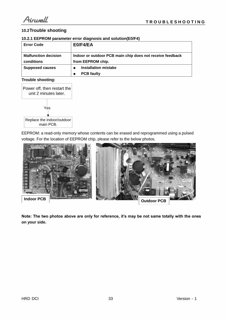
10.2.1 EEPROM parameter error diagnosis and solution(E0/F4)
Error Code E0/F4/EA
Malfunction decision
conditions
Indoor or outdoor PCB main chip does not receive feedback
from EEPROM chip.
Supposed causes ● Installation mistake
● PCB faulty
Trouble shooting:
Yes
Replace the indoor/outdoor
main PCB.
Power off, then restart the
unit 2 minutes later.
EEPROM: a read-only memory whose contents can be erased and reprogrammed using a pulsed
voltage. For the location of EEPROM chip, please refer to the below photos.
Note: The two photos above are only for reference, it’s may be not same totally with the ones
on your side.
Indoor PCB Outdoor PCB
T R O U B L E S H O O T I N G
Version - 1 34 HRD DCI
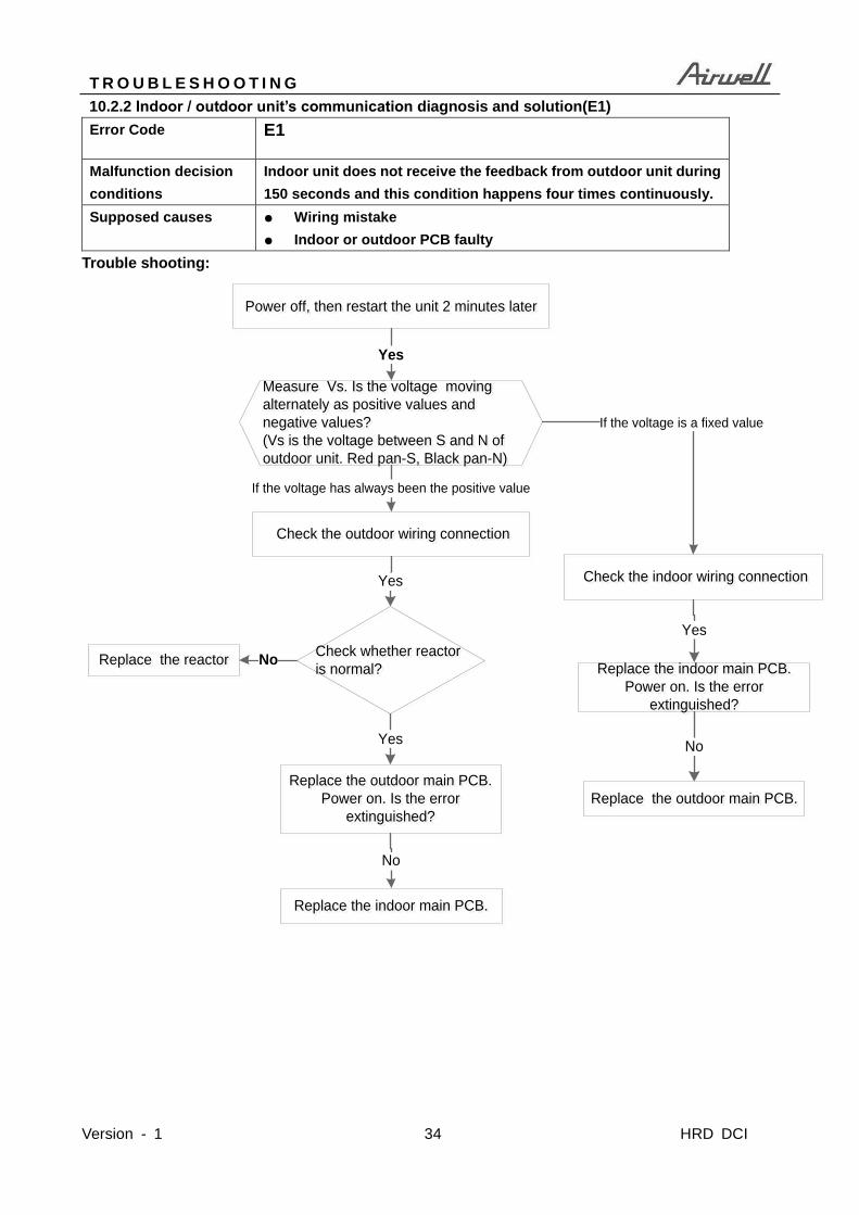
10.2.2 Indoor / outdoor unit’s communication diagnosis and solution(E1)
Error Code E1
Malfunction decision
conditions
Indoor unit does not receive the feedback from outdoor unit during
150 seconds and this condition happens four times continuously.
Supposed causes ● Wiring mistake
● Indoor or outdoor PCB faulty
Trouble shooting:
Measure Vs. Is the voltage moving
alternately as positive values and
negative values?
(Vs is the voltage between S and N of
outdoor unit. Red pan-S, Black pan-N)
Measure Vs. Is the voltage moving
alternately as positive values and
negative values?
(Vs is the voltage between S and N of
outdoor unit. Red pan-S, Black pan-N)
If the voltage has always been the positive value
Power off, then restart the unit 2 minutes laterPower off, then restart the unit 2 minutes later
If the voltage is a fixed value
Replace the outdoor main PCB.
Power on. Is the error
extinguished?
Replace the outdoor main PCB.
Power on. Is the error
extinguished?
Check the outdoor wiring connection Check the outdoor wiring connection
Replace the indoor main PCB.
Power on. Is the error
extinguished?
Replace the indoor main PCB.
Power on. Is the error
extinguished?
Yes
Replace the outdoor main PCB.Replace the outdoor main PCB.
No
Replace the indoor main PCB.Replace the indoor main PCB.
No
Check the indoor wiring connection Check the indoor wiring connectionYes
Yes
Check whether reactor
is normal?
Check whether reactor
is normal?
Yes
Replace the reactorReplace the reactor No

T R O U B L E S H O O T I N G
HRD DCI 35 Version - 1
Remark:
Use a multimeter to test the DC voltage
between 2 port and 3 port of outdoor unit.
The red pin of multimeter connects with 2
port while the black pin is for 3 port.
When AC is normal running, the voltage is
moving alternately as positive values and
negative values
If the outdoor unit has malfunction, the
voltage has always been the positive
value
While if the indoor unit has malfunction,
the voltage is a fixed value.
Remark:
Use a multimeter to test the resistance
of the reactor which does not connect
with capacitor.
The normal value should be around zero
ohm. Otherwise, the reactor must have
malfunction.

T R O U B L E S H O O T I N G
Version - 1 36 HRD DCI
10.2.3 Fan speed is operating outside of the normal range diagnosis and solution(E3/F5)
Error Code E3/F5
Malfunction decision
conditions
When indoor fan speed keeps too low (300RPM) or too high
(1500RPM) for certain time, the unit will stop and the LED will
display the failure.
Supposed causes ● Wiring mistake
● Fan ass’y faulty
● Fan motor faulty
● PCB faulty
Trouble shooting:
Power off, then restart the
unit 2 minutes later. Is it
still displaying the error
code?
Shut off the power supply,
Rotate the fan by hand.
Does it turn easily
properly?
The unit operates normally.
Find out the cause and
resolve it For example,
whether the fan is blocked or
the screws which fix the fan
are tighten
Check the wiring of fan
motor. Is it improperly?
No
Yes
No
Ensure proper connections.No
NoReplace the fan motor
Yes
Yes
Check whether the main
PCB is normal through
index 1
Yes
Replace the main PCBNo

T R O U B L E S H O O T I N G
HRD DCI 37 Version - 1
Index1:
1:Indoor or Outdoor DC Fan Motor(control chip is in fan motor)
Power on and when the unit is in standby, measure the voltage of pin1-pin3, pin4-pin3 in fan motor
connector. If the value of the voltage is not in the range showing in below table, the PCB must has
problems and need to be replaced.
DC motor voltage input and output
NO. Color Signal Voltage
1 Red Vs/Vm 280V~380V
2 --- --- ---
3 Black GND 0V
4 White Vcc 14-18.5V
5 Yellow Vsp 0~5.6V
6 Blue FG 14-18.5V
2. Outdoor DC Fan Motor (control chip is in outdoor PCB)
Power on ,and check if the fan can run normally, if the fan can run normally, the PCB must has
problems and need to be replaced, If the fan can’t run normally, measure the resistance of each two
pins. If the resistance is not equal to each other, the fan motor must have problems and need to be
replaced, otherwise the PCB must has problems and need to be replaced.

T R O U B L E S H O O T I N G
Version - 1 38 HRD DCI
3. Indoor AC Fan Motor
Power on and set the unit running in fan mode at high fan speed. After running for 15 seconds,
measure the voltage of pin1 and pin2. If the value of the voltage is less than 100V(208~240V power
supply)or 50V(115V power supply), the PCB must has problems and need to be replaced.

T R O U B L E S H O O T I N G
HRD DCI 39 Version - 1
10.2.4 Intelligent eye module error diagnosis and solution(EF)
Trouble shooting:
Power off, then restart the
unit 2 minutes later. Is it
still displaying the error
code?
The unit operates normally.
Check the wiring of
intelligent eye module. Is it
improperly?
No
Yes
Ensure proper connections.No
Replace the intelligent eye
module
Yes

T R O U B L E S H O O T I N G
Version - 1 40 HRD DCI
10.2.5 Open circuit or short circuit of temperature sensor diagnosis and solution
(E4/E5/F1/F2/F3)
Error Code E4/E5/F1/F2/F3
Malfunction decision
conditions
If the sampling voltage is lower than 0.06V or higher than 4.94V,
the LED will display the failure.
Supposed causes ● Wiring mistake
● Sensor faulty
● PCB faulty Trouble shooting:
Check the connection
between temperature
sensor and PCB.
Correct the connectionNo
Yes
Replace indoor or outdoor
main PCB
Measure the resistance
value of the sensor Repalce the sensorNo
Yes

T R O U B L E S H O O T I N G
HRD DCI 41 Version - 1
10.2.6 Communication error between the indoor PCB and display board (Eb)
Error Code Eb
Malfunction decision
conditions
Indoor PCB does not receive feedback from Display board.
Supposed causes ● Wiring mistake
● PCB faulty
● Display board malfunction
Trouble shooting:
Power off, then restart the unit
2 minutes later
Replace the indoor main PCB
Yes
Replace the Display board
Check the wirings
and connection
Yes
No Correct the connection
or replace the wirings
Yes
T R O U B L E S H O O T I N G
Version - 1 42 HRD DCI
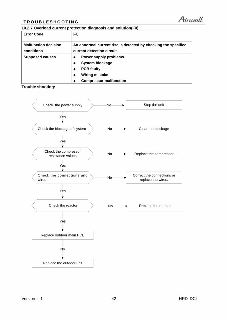
10.2.7 Overload current protection diagnosis and solution(F0)
Error Code F0
Malfunction decision
conditions
An abnormal current rise is detected by checking the specified
current detection circuit.
Supposed causes ● Power supply problems.
● System blockage
● PCB faulty
● Wiring mistake
● Compressor malfunction
Trouble shooting:
Check the power supply
Check the connections and
wires
Stop the unitNo
Yes
NoCorrect the connections or
replace the wires.
Yes
Replace outdoor main PCB
Yes
Check the reactor No Replace the reactor
Check the blockage of system
Yes
No Clear the blockage
Check the compressor
resistance values
Yes
No Replace the compressor
Replace the outdoor unit
No

T R O U B L E S H O O T I N G
HRD DCI 43 Version - 1
10.2.8 IPM malfunction or IGBT over-strong current protection diagnosis and solution(P0)
Error Code P0
Malfunction decision
conditions
When the voltage signal that IPM send to compressor drive chip
is abnormal, the display LED will show “P0” and AC will turn off.
Supposed causes ● Wiring mistake
● IPM malfunction
● Outdoor fan ass’y faulty
● Compressor malfunction
● Outdoor PCB faulty
Trouble shooting:
Check the wiring between main PCB
and compressor
Correct the connection or replace
the wires and connectors.Yes
No
Check the IPM No
Yes
Replace the IPM board or replace
the main PCB
Check the outdoor fan and the
outdoor unit ventilationNo
Please refer to the solution of 【Fan
Speed Has Been Out Of Control】malfunction
Yes
Check the compressor resistance
valuesNo Replace the compressor.
Yes
Replace the outdoor main PCB
IPM continuity check
Turn off the power, let the large capacity electrolytic capacitors discharge completely, and dismount the IPM. Use a digital
tester to measure the resistance between P and UVWN; UVW and N.
Digital tester Normal resistance value Digital tester Normal resistance value
(+)Red (-)Black
∞
(Several MΩ)
(+)Red (-)Black
∞
(Several MΩ) P
N U
N U V
V W
W (+)Red

T R O U B L E S H O O T I N G
Version - 1 44 HRD DCI
10.2.9 Over voltage or too low voltage protection diagnosis and solution(P1)
Error Code P1
Malfunction decision
conditions
An abnormal voltage rise or drop is detected by checking the
specified voltage detection circuit.
Supposed causes ● Power supply problems.
● System leakage or block
● PCB faulty
Trouble shooting:
Check the power supply
Check the connections and
wires
Stop the unitNo
Yes
NoCorrect the connections or
replace the wires.
Yes
Replace the reactor
Yes
No Replace the IPM board
Power on and when the unit is
in standby, Check the voltage
between P and N
Check the reactor
Yes
No Replace outdoor main PCB
Remark:
Measure the DC voltage
between P and N port. The
normal value should be
around 310V. P N

T R O U B L E S H O O T I N G
HRD DCI 45 Version - 1
10.2.10 High temperature protection of IPM diagnosis and solution (P2)
Error Code P2
Malfunction decision
conditions
If the temperature of IPM module is higher than limited value, the
LED will display the failure.
Supposed causes ● IPM radiator problem
● PCB faulty
Trouble shooting:
Yes
Tighten the screws and apply
silicon grease.
Tighten the screws and apply
silicon grease.Replace the outdoor control PCB.Replace the outdoor control PCB.
No
Check if the fastening screws
on the PCB and IPM radiator
are fixed tightly.

T R O U B L E S H O O T I N G
Version - 1 46 HRD DCI
10.2.11 Inverter compressor drive error diagnosis and solution(P4)
Error Code P4
Malfunction decision
conditions
An abnormal inverter compressor drive is detected by a special
detection circuit, including communication signal detection,
voltage detection, compressor rotation speed signal detection
and so on.
Supposed causes ● Wiring mistake
● IPM malfunction
● Outdoor fan ass’y faulty
● Compressor malfunction
● Outdoor PCB faulty
Trouble shooting:
Check the wiring between main PCB
and compressor
Correct the connection or replace
the wires and connectors.Yes
No
Check the IPM No
Yes
Replace the IPM board or replace
the main PCB
Check the outdoor fan and the
outdoor unit ventilationNo
Please refer to the solution of 【Fan
Speed Has Been Out Of Control】malfunction
Yes
Check the compressor resistance
valuesNo Replace the compressor.
Yes
Replace the outdoor main PCB

T R O U B L E S H O O T I N G
HRD DCI 47 Version - 1
Main parts check
1. Temperature sensor checking
Disconnect the temperature sensor from PCB, measure the resistance value with a tester.
Temperature Sensors.
Room temp.(T1) sensor,
Indoor coil temp.(T2) sensor,
Outdoor coil temp.(T3) sensor,
Outdoor ambient temp.(T4) sensor,
Compressor discharge temp.(T5) sensor.
Measure the resistance value of each winding by using the multi-meter.
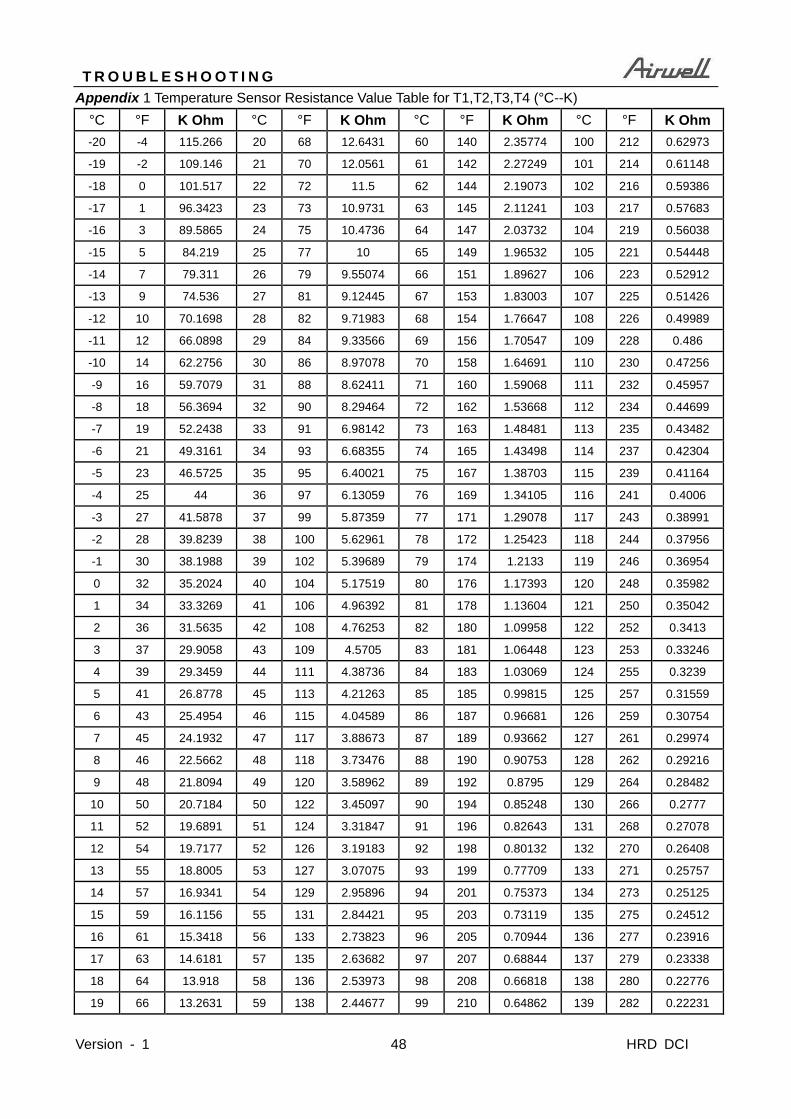
T R O U B L E S H O O T I N G
Version - 1 48 HRD DCI
Appendix 1 Temperature Sensor Resistance Value Table for T1,T2,T3,T4 (°C--K)
°C °F K Ohm °C °F K Ohm °C °F K Ohm °C °F K Ohm
-20 -4 115.266 20 68 12.6431 60 140 2.35774 100 212 0.62973
-19 -2 109.146 21 70 12.0561 61 142 2.27249 101 214 0.61148
-18 0 101.517 22 72 11.5 62 144 2.19073 102 216 0.59386
-17 1 96.3423 23 73 10.9731 63 145 2.11241 103 217 0.57683
-16 3 89.5865 24 75 10.4736 64 147 2.03732 104 219 0.56038
-15 5 84.219 25 77 10 65 149 1.96532 105 221 0.54448
-14 7 79.311 26 79 9.55074 66 151 1.89627 106 223 0.52912
-13 9 74.536 27 81 9.12445 67 153 1.83003 107 225 0.51426
-12 10 70.1698 28 82 9.71983 68 154 1.76647 108 226 0.49989
-11 12 66.0898 29 84 9.33566 69 156 1.70547 109 228 0.486
-10 14 62.2756 30 86 8.97078 70 158 1.64691 110 230 0.47256
-9 16 59.7079 31 88 8.62411 71 160 1.59068 111 232 0.45957
-8 18 56.3694 32 90 8.29464 72 162 1.53668 112 234 0.44699
-7 19 52.2438 33 91 6.98142 73 163 1.48481 113 235 0.43482
-6 21 49.3161 34 93 6.68355 74 165 1.43498 114 237 0.42304
-5 23 46.5725 35 95 6.40021 75 167 1.38703 115 239 0.41164
-4 25 44 36 97 6.13059 76 169 1.34105 116 241 0.4006
-3 27 41.5878 37 99 5.87359 77 171 1.29078 117 243 0.38991
-2 28 39.8239 38 100 5.62961 78 172 1.25423 118 244 0.37956
-1 30 38.1988 39 102 5.39689 79 174 1.2133 119 246 0.36954
0 32 35.2024 40 104 5.17519 80 176 1.17393 120 248 0.35982
1 34 33.3269 41 106 4.96392 81 178 1.13604 121 250 0.35042
2 36 31.5635 42 108 4.76253 82 180 1.09958 122 252 0.3413
3 37 29.9058 43 109 4.5705 83 181 1.06448 123 253 0.33246
4 39 29.3459 44 111 4.38736 84 183 1.03069 124 255 0.3239
5 41 26.8778 45 113 4.21263 85 185 0.99815 125 257 0.31559
6 43 25.4954 46 115 4.04589 86 187 0.96681 126 259 0.30754
7 45 24.1932 47 117 3.88673 87 189 0.93662 127 261 0.29974
8 46 22.5662 48 118 3.73476 88 190 0.90753 128 262 0.29216
9 48 21.8094 49 120 3.58962 89 192 0.8795 129 264 0.28482
10 50 20.7184 50 122 3.45097 90 194 0.85248 130 266 0.2777
11 52 19.6891 51 124 3.31847 91 196 0.82643 131 268 0.27078
12 54 19.7177 52 126 3.19183 92 198 0.80132 132 270 0.26408
13 55 18.8005 53 127 3.07075 93 199 0.77709 133 271 0.25757
14 57 16.9341 54 129 2.95896 94 201 0.75373 134 273 0.25125
15 59 16.1156 55 131 2.84421 95 203 0.73119 135 275 0.24512
16 61 15.3418 56 133 2.73823 96 205 0.70944 136 277 0.23916
17 63 14.6181 57 135 2.63682 97 207 0.68844 137 279 0.23338
18 64 13.918 58 136 2.53973 98 208 0.66818 138 280 0.22776
19 66 13.2631 59 138 2.44677 99 210 0.64862 139 282 0.22231

T R O U B L E S H O O T I N G
HRD DCI 49 Version - 1
Appendix 2 Temperature Sensor Resistance Value Table for T5 (°C --K)
°C °F K Ohm °C °F K Ohm °C °F K Ohm °C °F K Ohm
-20 -4 542.7 20 68 69.66 60 140 13.59 100 212 3.702
-19 -2 511.9 21 70 65.62 61 142 13.11 101 214 3.595
-18 0 483 22 72 62.73 62 144 12.65 102 216 3.492
-17 1 455.9 23 73 59.98 63 145 12.21 103 217 3.392
-16 3 430.5 24 75 58.37 64 147 11.79 104 219 3.296
-15 5 406.7 25 77 54.89 65 149 11.38 105 221 3.203
-14 7 384.3 26 79 52.53 66 151 10.99 106 223 3.113
-13 9 363.3 27 81 50.28 67 153 10.61 107 225 3.025
-12 10 343.6 28 82 49.14 68 154 10.25 108 226 2.941
-11 12 325.1 29 84 46.11 69 156 9.902 109 228 2.86
-10 14 308.7 30 86 44.17 70 158 9.569 110 230 2.781
-9 16 291.3 31 88 42.33 71 160 9.248 111 232 2.704
-8 18 275.9 32 90 40.57 72 162 9.94 112 234 2.63
-7 19 261.4 33 91 39.89 73 163 9.643 113 235 2.559
-6 21 248.8 34 93 38.3 74 165 9.358 114 237 2.489
-5 23 234.9 35 95 35.78 75 167 9.084 115 239 2.422
-4 25 222.8 36 97 34.32 76 169 8.82 116 241 2.357
-3 27 211.4 37 99 32.94 77 171 8.566 117 243 2.294
-2 28 200.7 38 100 31.62 78 172 8.321 118 244 2.233
-1 30 190.5 39 102 30.36 79 174 8.086 119 246 2.174
0 32 180.9 40 104 29.15 80 176 6.859 120 248 2.117
1 34 171.9 41 106 28 81 178 6.641 121 250 2.061
2 36 163.3 42 108 26.9 82 180 6.43 122 252 2.007
3 37 155.2 43 109 25.86 83 181 6.228 123 253 1.955
4 39 148.6 44 111 24.85 84 183 6.033 124 255 1.905
5 41 140.4 45 113 23.89 85 185 5.844 125 257 1.856
6 43 133.5 46 115 22.89 86 187 5.663 126 259 1.808
7 45 128.1 47 117 22.1 87 189 5.488 127 261 1.762
8 46 121 48 118 21.26 88 190 5.32 128 262 1.717
9 48 115.2 49 120 20.46 89 192 5.157 129 264 1.674
10 50 109.8 50 122 19.69 90 194 5 130 266 1.632
11 52 104.6 51 124 19.96 91 196 4.849
12 54 99.69 52 126 19.26 92 198 4.703
13 55 95.05 53 127 18.58 93 199 4.562
14 57 90.66 54 129 16.94 94 201 4.426
15 59 86.49 55 131 16.32 95 203 4.294
16 61 82.54 56 133 15.73 96 205 4.167
17 63 79.79 57 135 15.16 97 207 4.045
18 64 75.24 58 136 14.62 98 208 3.927
19 66 71.86 59 138 14.09 99 210 3.812

T R O U B L E S H O O T I N G
Version - 1 50 HRD DCI
2.Compressor checking
Measure the resistance value of each winding by using the tester.
Position Resistance Value
ASN98D22UFZ ASM135D23UFZ ATF235D22UMT
Blue - Red 1.57Ω
(20℃/68℉)
1.75Ω
(20℃/68℉)
0.75Ω
(20℃/68℉) Blue - Black
Red - Blue

EXPLODED VIEW AND SPARE PART LIST
HRD DCI 51 Version - 1
11. Exploded view and spare part list
11.1 Exploded view of model: AWSI-HRD009-N91, AWSI-HRD012-N91

EXPLODED VIEW AND SPARE PART LIST
Version - 1 52 HRD DCI
11.2 Spare part list of model: AWSI-HRD009-N91
No. BOM Code Part Name Quantity
1 12122000017996 Panel assembly 1
2 12122000017982 Air filter 2
3 17222000022148 Display box subassembly 1
3.1 12122000017296 Display box 1
3.2 17122000035168 Display board subassembly 1
3.3 11201007000599 Room Temperature Sensor 1
4 12122000017981 Cover of electrical equipment 1
5 12122000017992 Panel frame assembly 1
5.1 12122000018201 Intelligent eye fixing seat 1
5.2 17422000000355 Smart Eye Subassembly 1
9 12122000017989 Horizontal louver assembly 1
10 15822000007156 Evaporator Assembly 1
11 12122000017990 Fan motor cover 1 12 11002015000051 Brushless DC Motor 1
13 12122000000350 Bearing holder 1
14 12622000000006 Bearing base 1
15 12100102000436 Cross flow fan 1
16 12122000015241 Chassis support unit 2
17 12122000017986 Chassis assembly 1
17.1 11002010000686 Stepper motor 1
17.1 11002010000161 stepper motor 1
17.2 12122000017987 vortex tongue bar 1
17.3 12122000018202 Connecting rod of louver 1
17.3 12122000018222 Connecting rod of louver 1
17.4 12122000018203 drive Louver 10
17.5 12122000000318 Louver base 1
17.6 12122000000320 Louver base 1
17.9 12122000017983 Super negative ion cover plate 1
18 12122000013136 pipe clamp board 1
19 12222000005042 Installation plate 1
20 17222000022168 Electronic control box subassembly (Mid-and low-end) 1
20.2 12122000017423 Cover of electronic control box subassembly 1
20.3 12122000014682 Electronic control box subassembly 1
20.4 17122000035188 Main control board subassembly 1
20.6 17400401000576 Wire joint 1
20.7 11201007000126 Pipe Temperature Sensor 1
21 12122000017442 Cover board for wiring 1
22 17317000A02580 Remote controller 1
23 12600701000039 Seal ring 1
24 12100509000061 Drain hose 1
28 12100501000032 Drain Hose 1
40 12100204000685 air fresh filter 1
46 15500406000010 Copper nut 1
46 15500406000016 Copper nut 1

EXPLODED VIEW AND SPARE PART LIST
HRD DCI 53 Version - 1
11.3 Spare part list of model: AWSI-HRD012-N91
No. BOM Code Part Name Quantity
1 12122000017996 Panel assembly 1
2 12122000017982 Air filter 2
3 17222000022148 Display box subassembly 1
3.1 12122000017296 Display box 1
3.2 17122000035168 Display board subassembly 1
3.3 11201007000599 Room Temperature Sensor 1
4 12122000017981 Cover of electrical equipment 1
5 12122000017992 Panel frame assembly 1
5.1 12122000018201 Intelligent eye fixing seat 1
5.2 17422000000355 Smart Eye Subassembly 1
9 12122000017989 Horizontal louver assembly 1
10 15822000007156 Evaporator Assembly 1
11 12122000017990 Fan motor cover 1
12 11002015000051 Brushless DC Motor 1
13 12122000000350 Bearing holder 1
14 12622000000006 Bearing base 1
15 12100102000436 Cross flow fan 1
16 12122000015241 Chassis support unit 2
17 12122000017986 Chassis assembly 1
17.1 11002010000686 Stepper motor 1
17.1 11002010000161 stepper motor 1
17.2 12122000017987 vortex tongue bar 1
17.3 12122000018202 Connecting rod of louver 1
17.3 12122000018222 Connecting rod of louver 1
17.4 12122000018203 drive Louver 10
17.5 12122000000318 Louver base 1
17.6 12122000000320 Louver base 1
17.9 12122000017983 Super negative ion cover plate 1
18 12122000013136 pipe clamp board 1
19 12222000005042 Installation plate 1
20 17222000022188 Electronic control box subassembly (Mid-and low-end) 1
20.2 12122000017423 Cover of electronic control box subassembly 1
20.3 12122000014682 Electronic control box subassembly 1
20.4 17122000035189 Main control board subassembly 1
20.6 17400401000576 Wire joint 1
20.7 11201007000126 Pipe Temperature Sensor 1
21 12122000017442 Cover board for wiring 1
22 17317000A02580 Remote controller 1
23 12600701000039 Seal ring 1
24 12100509000061 Drain hose 1
28 12100501000032 Drain Hose 1
40 12100204000685 air fresh filter 1
46 15500406000010 Copper nut 1
46 15500406000016 Copper nut 1

EXPLODED VIEW AND SPARE PART LIST
Version - 1 54 HRD DCI
11.4 Exploded view of model: AWAU-YRD009-H91, AWAU-YRD012-H91

EXPLODED VIEW AND SPARE PART LIST
HRD DCI 55 Version - 1
11.5 Spare part list of model: AWAU-YRD009-H91
No. BOM Code Part Name Quantity
1 11201007002020 Room Temperature Sensor 1
2 15822000007196 Condenser Assembly 1
3 11201007000069 Pipe Temperature Sensor 1
4 12222000004186 Right side plate 1
5 12100701000015 Big handle assembly 1
6 12122000007150 Water collector 1
7 12222000004326 Chassis assembly 1
8 12222000A02014 Front panel assembly 1
9 12122000A26900 Air outlet grille 1
10 12100105000051 Axial flow fan 1
11 11002015006761 Brushless DC Motor 1
12 12222200002154 Supporter subassembly of fan motor 1
13 12222000008484 Left side plate assembly of cabinet 1
14 12222200001291 Top cover assembly 1
15 12222200001146 Partition board assembly 1
16 17400306000053 Reactor 1
17 15422000013012 4-way Valve Assembly 1
17.1 15500204000021 Gas valve 1
17.2 15500216000026 4-way Valve 1
17.3 12222000002571 Valve plate 1
17.4 15122200002744 Muffler subassembly 1
18 15422000012992 Liquid valve Assembly 1
18.1 15500208000028 Liquid valve 1
18.2 15500213000178 Electronic expansion valve 1
19 11103020003399 DC Inverter Rotary Compressor 1
20 11201007000005 Discharge Temperature Sensor 1
21 17222000022228 Electronic control box subassembly 1
21.1 12122000006856 Electronic installing box subassembly 1
21.2 17122000033461 Outdoor main control board subassembly 1
21.3 12122000014683 Support of electronic control box 1
21.5 12222000001325 Electronic installing box subassembly 1
22 15500406000010 Copper nut 1
22 15500406000016 Copper nut 1
29 17402001A00003 Crankcase electric heater 1
30 17402002000042 Electric heating tube 1
32 12222000002259 Terminal board 1
33 17400401000016 Wire joint 1
99 17401203000802 Compressor wire subassembly 1

EXPLODED VIEW AND SPARE PART LIST
Version - 1 56 HRD DCI
11.6 Spare part list of model: AWAU-YRD012-H91
No. BOM Code Part Name Quantity
1 11201007002020 Room Temperature Sensor 1
2 15822000007196 Condenser Assembly 1
3 11201007000069 Pipe Temperature Sensor 1
4 12222000004186 Right side plate 1
5 12100701000015 Big handle assembly 1
6 12122000007150 Water collector 1
7 12222000004326 Chassis assembly 1
8 12222000A02014 Front panel assembly 1
9 12122000A26900 Air outlet grille 1
10 12100105000051 Axial flow fan 1
11 11002015006761 Brushless DC Motor 1
12 12222200002154 Supporter subassembly of fan motor 1
13 12222000008484 Left side plate assembly of cabinet 1
14 12222200001291 Top cover assembly 1
15 12222200001146 Partition board assembly 1
16 17400306000053 Reactor 1
17 15422000013012 4-way Valve Assembly 1
17.1 15500204000021 Gas valve 1
17.2 15500216000026 4-way Valve 1
17.3 12222000002571 Valve plate 1
17.4 15122200002744 Muffler subassembly 1
18 15422000012992 Liquid valve Assembly 1
18.1 15500208000028 Liquid valve 1
18.2 15500213000178 Electronic expansion valve 1
19 11103020003399 DC Inverter Rotary Compressor 1
20 11201007000005 Discharge Temperature Sensor 1
21 17222000022208 Electronic control box subassembly 1
21.1 12122000006856 Electronic installing box subassembly 1
21.2 17122000033454 Outdoor main control board subassembly 1
21.3 12122000014683 Support of electronic control box 1
21.5 12222000001325 Electronic installing box subassembly 1
22 15500406000010 Copper nut 1
22 15500406000016 Copper nut 1
29 17402001A00003 Crankcase electric heater 1
30 17402002000042 Electric heating tube 1
32 12222000002259 Terminal board 1
33 17400401000016 Wire joint 1
99 17401203000802 Compressor wire subassembly 1

HRD DCI 57 Version - 1
SERVICE MANUAL
HRD DCI Series