HR2600 Manual
12
Doc’s Electronics http://hr2510.homeip.net:2510/ Doc’s Electronics http://hr2510.homeip.net:2510/ 10 Meter Amateur Mobile Transceiver PRESIDENT HR2600
-
Upload
electronico69 -
Category
Documents
-
view
16 -
download
0
Transcript of HR2600 Manual

D o c ’s E l e c t r o n i c s h t t p : / / h r 2 5 1 0 . h o m e i p . n e t : 2 5 1 0 /D o c ’s E l e c t r o n i c s h t t p : / / h r 2 5 1 0 . h o m e i p . n e t : 2 5 1 0 /
10 Meter AmateurMobile Transceiver
PRESIDENT
HR2600

D o c ’s E l e c t r o n i c s h t t p : / / h r 2 5 1 0 . h o m e i p . n e t : 2 5 1 0 /D o c ’s E l e c t r o n i c s h t t p : / / h r 2 5 1 0 . h o m e i p . n e t : 2 5 1 0 /
Welcome! . . . . . . . . . . . . . . . . . . . . . . . . . . . . . . . . . . . . . . . . .2 Unpacking . . . . . . . . . . . . . . . . . . . . . . . . . . . . . . . . . . . . . .2Controls and Functions . . . . . . . . . . . . . . . . . . . . . . . . . . . 3-5Front Panel Connector . . . . . . . . . . . . . . . . . . . . . . . . . . . . . 6CTCSS Control . . . . . . . . . . . . . . . . . . . . . . . . . . . . . . . . . . . 7 Setting & Using CTCSS . . . . . . . . . . . . . . . . . . . . . . . . . . .7 Switch Settings for S301 . . . . . . . . . . . . . . . . . . . . . . . . . . .8Rear Panel Connectors . . . . . . . . . . . . . . . . . . . . . . . . . . . . . 9 Power Connector . . . . . . . . . . . . . . . . . . . . . . . . . . . . . . . 9 Antenna Connector . . . . . . . . . . . . . . . . . . . . . . . . . . . . . 10Installation . . . . . . . . . . . . . . . . . . . . . . . . . . . . . . . . . . . . . 11 Transceiver Mounting . . . . . . . . . . . . . . . . . . . . . . . . . . . 11 Mobile Antenna . . . . . . . . . . . . . . . . . . . . . . . . . . . . . . . . 11 Ground Information . . . . . . . . . . . . . . . . . . . . . . . . . . . . 11 Power Cord Connection . . . . . . . . . . . . . . . . . . . . . . . . . 11Operation . . . . . . . . . . . . . . . . . . . . . . . . . . . . . . . . . . . . . . 12 Selecting a Frequency . . . . . . . . . . . . . . . . . . . . . . . . . . .12 VFO Operation . . . . . . . . . . . . . . . . . . . . . . . . . . . . . . . . 12 Repeater Operation . . . . . . . . . . . . . . . . . . . . . . . . . . . . . 12 USB/LSB/AM/FM Operation . . . . . . . . . . . . . . . . . . . . . 12 Noise Blanker . . . . . . . . . . . . . . . . . . . . . . . . . . . . . . . . . 12 F. Lock . . . . . . . . . . . . . . . . . . . . . . . . . . . . . . . . . . . . . . 12 CW Operation . . . . . . . . . . . . . . . . . . . . . . . . . . . . . . . . . 13 Receive Scanning . . . . . . . . . . . . . . . . . . . . . . . . . . . . . . 13 Scanning Operation . . . . . . . . . . . . . . . . . . . . . . . . . . . . . 13 Multifunction Meter . . . . . . . . . . . . . . . . . . . . . . . . . . . . 14 S/RF Meter . . . . . . . . . . . . . . . . . . . . . . . . . . . . . . . . . . . 14 MOD Meter . . . . . . . . . . . . . . . . . . . . . . . . . . . . . . . . . . 14 SWR CAL Meter . . . . . . . . . . . . . . . . . . . . . . . . . . . . . . 14 SWR Meter . . . . . . . . . . . . . . . . . . . . . . . . . . . . . . . . . . . 15Specifications . . . . . . . . . . . . . . . . . . . . . . . . . . . . . . . . . . . 16 General . . . . . . . . . . . . . . . . . . . . . . . . . . . . . . . . . . . . . . 16 Transmitter . . . . . . . . . . . . . . . . . . . . . . . . . . . . . . . . . . . 16 Receiver . . . . . . . . . . . . . . . . . . . . . . . . . . . . . . . . . . . . . 16Troubleshooting . . . . . . . . . . . . . . . . . . . . . . . . . . . . . . . . . 17Amateur Radio Operation . . . . . . . . . . . . . . . . . . . . . . 18-19
Warranty . . . . . . . . . . . . . . . . . . . . . . . . . . . . . . . . . . . . . . 20
Contents One Year Limited Warranty
ELEMENTS OF WARRANTY: UNIDEN warrants, for the duration of thiswarranty, UNIDEN CB Product (hereinafter referred to as the Product) to be freefrom defects in materials and craftsmanship with only the limitations or exclusionsset out below.WARRANTY DURATION: This warranty shall terminate and be of no furthereffect one (1) year after the date of the original purchase of the Product or at thetime the Product is (A) damaged or not maintained as reasonable or necessary, (B)modified, (C) improperly installed, (D) repaired by someone other than warrantorfor a defect or malfunction covered by this warranty, (E) used in a manner orpurpose for which the Product was not intended, or (F) sold by the originalpurchaser.STATEMENT OF REMEDY: In the event that the product does not conform tothis warranty at any time while this warranty is in effect, warrantor will repair thedefect and return it to you without charge for parts, service, or any other costincurred by warrantor or its representatives in connection with the performance ofthis warranty. THIS WARRANTY DOES NOT COVER OR PROVIDE FOR THEREIMBURSEMENT OF PAYMENT OF INCIDENTAL OR CONSEQUENTIALDAMAGES. Some states do not allow this exclusion or limitation of incidental orconsequential damages so the above limitation or exclusion may not apply to you.WARRANTY REGISTRATION CARD: In order to facilitate the servicing ofthis warranty by warrantor, the Warranty Registration Card should be returned tothe warrantor. However, return of the Warranty Registration Card is not a precondi-tion of this warranty, and this warranty will be observed by the warrantor whetheror not the Warranty Registration Card is returned, provided that other satisfactoryevidence of the date of purchase is provided.PROCEDURE FOR OBTAINING PERFORMANCE OF WARRANTY: In theevent that the Product does not conform to this warranty, the Product should beshipped or delivered, freight prepaid, with evidence of original purchase, towarrantor at:
UNIDEN CUSTOMER SERVICE CENTER9900 Westpoint DriveIndianapolis, IN 46250
LEGAL REMEDIES: This warranty gives you specific legal rights, and youmay also have other rights which vary from state to state. This warranty is voidoutside of the United States of America.
WARRANTOR: UNIDEN CORPORATION OF AMERICA (“UNIDEN”.)

D o c ’s E l e c t r o n i c s h t t p : / / h r 2 5 1 0 . h o m e i p . n e t : 2 5 1 0 /D o c ’s E l e c t r o n i c s h t t p : / / h r 2 5 1 0 . h o m e i p . n e t : 2 5 1 0 /
NOTES/MEMOS Welcome!To the world of 10 Meter amateur radio communications! You have purchased whatwe feel to be the finest 10 Meter mobile transceiver available. Your HR 2600 hasbeen designed using the latest state of the art electronics to give you years of troublefree service. To get the most from your HR 2600, please read this operating guidethoroughly.
WARNING: To operate this transceiver, you MUST have anFCC Radio Amateur Operator’s license. Operation of thisdevice without a license is ILLEGAL and carries heavypenalties.
Unpacking
HR 2600 10 Meter Transceiver
Dynamic Microphone with Channel Up/Down control
Transceiver & Microphone Mounting Brackets & Hardware
Power Cord with In-Line fuse holder Accessory Plug
(Jumpered for internal speaker use)
Accessory Plug (With wires for connecting accessories)
This operating guide
We also recommend that you retain the original box and packing, as it makes aconvenient way to transport the unit.
Your HR 2600 is supplied with the following items. If any items are missing orappear damaged, DO NOT return the unit to the place of purchase. Instead, contactUniden Customer Service at (317) 842-2483, 8 am-5 pm EST, Monday throughFriday.

D o c ’s E l e c t r o n i c s h t t p : / / h r 2 5 1 0 . h o m e i p . n e t : 2 5 1 0 /D o c ’s E l e c t r o n i c s h t t p : / / h r 2 5 1 0 . h o m e i p . n e t : 2 5 1 0 /
Controls and Functions1. Mode Switch - This control is used to select the desired transmit mode. Themodes available are: CW, LSB, USB, AM, and FM.2. SWR/CAL Control - This control is used to adjust the calibration of the SWRmeter while in SWR CAL mode.3. RIT Control - The Receiver Incremental Tuning control is used to fine tune thereceived signal. This is used in USB and LSB modes to obtain maximum clarity ofreception, and in CW mode to control the pitch of the beat note. The RIT controlcan tune the receive frequency about ± 3 kHz. This control will not affect thetransmit frequency, or the frequency display, but will change the receive frequency4. RIT Switch - This switch enables or disables the RIT control. Press to enable(button down). Press again to disable (button up).5. RF Gain Control - This is used to vary the RF input to the receiver. This controlis used to help eliminate strong, adjacent signals6. Mic Gain Switch - Pressing this switch activates the built-in microphoneattenuator. This feature is designed to be used when operating the HR 2600 in highambient noise environments7. TX Switch - The TX switch is used to lock the transmitter on for tuningpurposes, except in CW mode. In CW mode the external key must be locked down.The microphone is disconnected unless the PTT switch is also depressed8. Meter Switch - This switch is used to select the operating mode for themultifunction meter. The meter modes are: S/RF, Modulation, SWR Calibrationsetting, and SWR. Each time the Meter switch is pushed, the next mode is selected.See the operation section for more information on meter usage. The currentlyselected mode is displayed above the meter.9. NB Switch - Pressing this switch enables the built in noise blanker. The noiseblanker in your HR 2600 is very effective in eliminating interference generated by,vehicle ignition systems.
NOTES/MEMOS

D o c ’s E l e c t r o n i c s h t t p : / / h r 2 5 1 0 . h o m e i p . n e t : 2 5 1 0 /D o c ’s E l e c t r o n i c s h t t p : / / h r 2 5 1 0 . h o m e i p . n e t : 2 5 1 0 /
Amateur Radio Operation - continuedEventually, you’ll probably want to get another, higher class of amateur license,with more privileges. Exams for Technician, General, Advanced, and Extra Classlicenses are given by three-member Volunteer Examiner Teams. Hundreds of examsessions are held across the country every month, most on weekends. (You can takethe Novice exam from a Volunteer Examiner Team, too, if it’s more convenient.)When you’re ready, you can get a schedule of exam opportunities in your area fromthe ARRL
We’ve mentioned the ARRL several times. That’s because the League is thenational organization that represents Amateur Radio in the United States. TheLeague has more than 150,000 members; most of them hams, but including lotsof hams-to-be. Here’s the address of ARRL Headquarters
The ARRL staff helped us prepare this section of the operating guide, and they wouldbe glad to hear from you if you need more information, or if you’d like to join!
The American Radio Relay League225 Main Street
Newington CT 06111
Controls and Functions - continued10. Dim Switch - Pressing the Dim switch dims the display backlighting. Press againto return backlighting to its normal (high) level.11. Scan Switch - The Scan control is used to scan up to 100 frequencies in each bandsegment. See the section on operation for more information on using the Scan Control.12. Span (Step Size) Switch - This control is used to select either 10 kHz, 1 KHz, or100 Hz steps for the VFO. The currently selected step is indicated by a line under therelevant digit on the Frequency Display.13. A and V - Pressing these controls will step up or down in frequency by the amountof the span control.14. Band Switch - Pressing this control will select one of the four band segments.Band segments are: a:28.0000 - 28.4999, b:28.5000-28.9999, c:29.0000-29.4999,and d:29.5000-29.6999 MHz. The currently selected band segment is displayed nextto the frequency display.15. F. Lock Switch -Pressing the Frequency Lock button will disable all frequencydetermining controls on the front panel (except RIT) and on the microphone, toprevent accidental changes of frequency.16. Digital VFO Control - The Variable Frequency Oscillator control is used to selectthe desired transmit and receive frequency. Tuning is continuous throughout the entirerange of the HR 2600, with no need to select band segments.17. Squelch Control - The Squelch control is used to adjust the squelch function,which eliminates the “rushing” sound between transmissions. Turning the squelchcontrol CCW until it clicks enables the auto squelch, eliminating the need to manuallyadjust the squelch.18. On/Off/Volume Control - This control is used to turn the unit on or off and toadjust the volume.19. RPT Switch - Pressing this control enables the 100 KHz frequency split for FMrepeater operation. When selected, a “P” is displayed above the band segment display.

D o c ’s E l e c t r o n i c s h t t p : / / h r 2 5 1 0 . h o m e i p . n e t : 2 5 1 0 /D o c ’s E l e c t r o n i c s h t t p : / / h r 2 5 1 0 . h o m e i p . n e t : 2 5 1 0 /
Controls and Functions - continued20. Multifunction Meter - This meter can display S/RF, Modulation, SWR Cal, orSWR. See item (8), Meter Switch and the operation section for more information.21. Frequency Display - The Frequency Display displays the currently selectedtransmit and receive frequency.22. Meter Mode Display - Displays the currently selected meter operating mode.23. Band Segment Display - Shows the currently selected band segment.24. Repeat Mode Display Shows a “P” if repeater mode is selected.25. TX Indicator - Illuminates when PTT or TX Switch is pressed, or CW key isdown.26. VFO Step Indicator - Displays the currently selected VFO step. (The photoshows 100Hz step selected).
27. Remote A and V switches - You can step up or down by the setting of the spancontrol using these controls. See the section on operation for more information.28. PTT Switch - The Push to Talk switch is used to control the transmit and receiveof your HR 2600. Press to transmit, and release to receive.
Amateur Radio OperationYour new President transceiver is designed to be the perfect “first radio” for anyoneentering the exciting world of Amateur Radio. From your home, car, or boat, you willfind that it opens a door to the world - literally! All you need is a source of electricalpower, a suitable antenna, and most important of all, an Amateur Radio Operator’sLicense issued by the Federal Communications Commission (FCC).You may already have a license. In fact, you may have been a ham operator for manyyears. But if you don’t have a license, you’ll find that it’s easy to get one, and there islots of help available. Here are a few tips to help you get started.First, go ahead and hook up the equipment. Use the receiver section to find out what’sgoing on. But don’t even think of transmitting until you get your license. That’svery important. Transmitting without a license is a violation of Federal Law that couldlead to severe penalties. Also, ham operators take the FCC rules very seriously andwant nothing to do with “bootleggers” - their term for people who operate without alicense.Second, find out if there’s a ham radio club in your area. There are thousands of themacross the country, so there’s probably at least one in or near your own community. Thepeople at the store where you bought your equipment may be able to tell you. If not,and you don’t hear anyone talking about a local club in your area as you tune aroundthe band with your receiver, write to the American Radio Relay League at the addressat the end of this section for information on how to contact their local affiliate. Mostclubs welcome newcomers, and would be glad to help you obtain your license.Next, start studying for your license. Don’t let the word “study” scare you, becausemost people can go from knowing absolutely nothing about radio to passing the basic(Novice) class license exam in less than 40 hours of study spread out over severalweeks. The test will be on basic radio regulations, a little bit of radio theory, and slowspeed Morse Code. Many clubs teach license classes (a fun and easy way to learn aboutAmateur Radio), and there are good books, cassette tapes, computer programs, and lotsof other study aids available. The ARRL publishes a book, Tune in the World withHam Radio which is usually packaged with two tape cassettes and has all you need toknow. But, don’t overlook the products of commercial publishers that you will see inradio and electronics stores.Finally, you’ll be ready to pass the exam. You won’t have to go to an imposing Federaloffice building in a big city to take the test, because these days, the FCC has hamvolunteers give all of the exams. For the Novice license, the examiners can be any twohams with General or higher class licenses who are at least 18 years old and not relatedto you. And, the Novice exam is free!The Novice class license will let you use your HR 2600 between 28.1 and 28.5 MHz -on CW (Morse Code) between 28.1 and 28.5 MHz, and on SSB (voice) between 28.3and 28.5 MHz. Your HR 2600 has more frequencies and operating modes built in,which you will be able to use once you have a General or higher class license. There’sno rush - your Novice license will be good for ten years, and even then you can renew itindefinitely.

D o c ’s E l e c t r o n i c s h t t p : / / h r 2 5 1 0 . h o m e i p . n e t : 2 5 1 0 /D o c ’s E l e c t r o n i c s h t t p : / / h r 2 5 1 0 . h o m e i p . n e t : 2 5 1 0 /
TroubleshootingIf your HR 2600 is not performing up to your expectations, please try these simplesteps. If you still cannot get satisfactory results after reading this manual and followingthe troubleshooting steps, please contact Uniden Customer Service at: (317) 842-2483.
Trouble CheckUnit will not turn on 1. Check power cord and all connections.No Power 2. Check power cord fuse.
3.. Check vehicle electrical system
4. Check unit grounding.
Poor Reception 1. Check & adjust squelch.
2. Check antenna.
3. Check antenna cable.
4. Check antenna connectors.
5. Check operating mode of radio.
Weak Transmission 1. Check antenna.
2. Check antenna cable.
3. Check antenna connectors.
4. Check operating mode of radio.
5. Check antenna SWR.
6. Check antenna grounding.
7. Check for corrosion on connectors.
Front Panel Connector
Microphone Connector
The microphone included with the HR 2600 is a 5005 dynamic microphone, withfrequency up and down switches. The view of the connector is facing the HR 2600front panel. The pin connections are as follows:
Pin
1&2
3&2
4&2
5&2
2
Connection
Microphone
PTT Switch
Channel Up Switch
Channel Down Switch
Common Ground
3 24
5 1Transmit (PTT)
Channel Up
Channel Down

D o c ’s E l e c t r o n i c s h t t p : / / h r 2 5 1 0 . h o m e i p . n e t : 2 5 1 0 /D o c ’s E l e c t r o n i c s h t t p : / / h r 2 5 1 0 . h o m e i p . n e t : 2 5 1 0 /
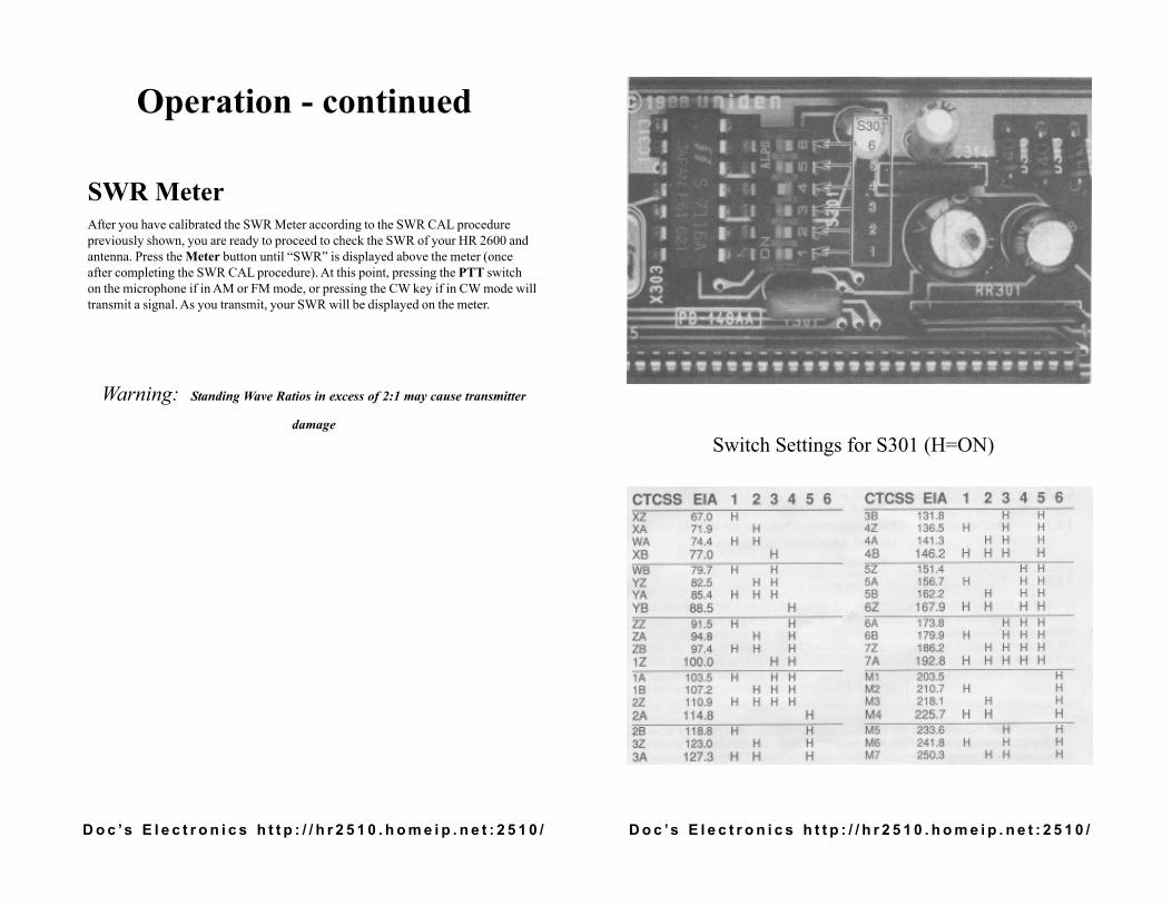
Setting & Using CTCSSThe HR 2600 has a built-in CTCSS encoding (Continuous Tone Coded SquelchSystem) for accessing repeaters. CTCSS is activated only in FM RPT mode ofoperation. To set the CTCSS frequency, proceed as follows:1. Place the unit top down on a non-scratching surface.2. Remove the cover screws for the bottom half of the case (see photo above). Usecaution when removing the bottom half of the case, since the speaker is connectedto the main board. Do not pull on the wires.3. Using the table at the right, set S301 for the desired CTCSS frequency. If noCTCSS tone is desired, place all switches (S301 -1 through S301-6) into either theon or off position.4. Replace the cover and securely fasten using the screws. Do not overtighten thescrews, or damage to the threads may result.5. To use CTCSS encode mode, place the mode switch into the FM position, andpress the RPT switch (down position). You are now ready for CTCSS encodedrepeater operation.Note: The CTCSS board in the HR 2600 is encode only. Receiver operation isnormal carrier squelch
CTCSS Control Specifications
D o c ’s E l e c t r o n i c s h t t p : / / h r 2 5 1 0 . h o m e i p . n e t : 2 5 1 0 /D o c ’s E l e c t r o n i c s h t t p : / / h r 2 5 1 0 . h o m e i p . n e t : 2 5 1 0 /
Operation - continued
SWR MeterAfter you have calibrated the SWR Meter according to the SWR CAL procedurepreviously shown, you are ready to proceed to check the SWR of your HR 2600 andantenna. Press the Meter button until “SWR” is displayed above the meter (onceafter completing the SWR CAL procedure). At this point, pressing the PTT switchon the microphone if in AM or FM mode, or pressing the CW key if in CW mode willtransmit a signal. As you transmit, your SWR will be displayed on the meter.
Warning: Standing Wave Ratios in excess of 2:1 may cause transmitter
damage
Switch Settings for S301 (H=ON)

D o c ’s E l e c t r o n i c s h t t p : / / h r 2 5 1 0 . h o m e i p . n e t : 2 5 1 0 /D o c ’s E l e c t r o n i c s h t t p : / / h r 2 5 1 0 . h o m e i p . n e t : 2 5 1 0 /
Rear Panel Connectors
Accessory ConnectorThere are two plugs for the accessory connector included with your HR 2600. One plugcontains only a jumper between pins 1 and 7, which is used only to enable theinternal speaker. The other plug is wired so that you can conveniently connectaccessories to your HR 2600. The view of the connector is facing the rearpanel of the unit. The pin connections and wiring color codes are as follows
Pin Wire Color Connection1 & 2 Red/Black External Speaker4 & 5 Blue/Black N.C.8 & 9 Black/Yellow CW Key (Yellow wire (pin 9) is “hot” side (positive) if there is any polarity on the key.)1 & 7 Red/White Internal Speaker (Jumper to use internal speaker, open if external speaker is connected.)3 & 6 n.c.
Power Connector
The power cord included with the HR 2600 is color coded. The red wire goes to +13.8V DC nominal and the black wire goes to ground. The HR 2600 is designed foroperation with a negative ground system only. The view of the power connector isfacing the rear panel of the HR 2600
Operation - continuedMultifunction MeterThe Multifunction Meter built in to your HR 2600 provides a number of usefulfunctions. These are:
S/RF MeterMOD MeterSWR CAL MeterSWR Meter
Every time you press the Meter button, the next function will be selected. When youreach the end of the functions, it will start over with the first. When in receive mode,the meter is always in the “S” function. (Received signal strength.)
S/RF MeterThe S/RF meter function provides a visual indication of relative received signalstrength and relative transmit power. To use the S/RF function, press the Meter buttonuntil “RF” is displayed over the meter display. The meter automatically switchesfunction depending on whether you are transmitting (RF Mode) or receiving (S mode).
MOD MeterThis function gives you an indication of the strength of your modulation whentransmitting. There is no function for this meter when receiving signals. To use theMOD function, press the Meter button until “MOD” is displayed over the meterdisplay.
SWR CAL MeterNote: The SWR CAL and SWR functions are not operative in USB and LSBmodes. You must select either AM, FM, or CW modes for calibrating andchecking SWR.This mode of the multifunction meter is used to calibrate the meter for the SWRfunction. To use this mode, press the Meter button until the small triangle is visibleunder the meter, near the right side. No other meter mode indications will be visibleat the same time. Press the PTT switch on the microphone or the TX button in AMor FM modes, or hold down the CW key in CW mode, and adjust the meter so thatit indicates to the triangle. Use the SWR CAL control for the adjustment. Whenyou have done this, you are ready to check the SWR.Note: Don’t forget that all transmissions must be properly identified, andremember to listen on the frequency before transmitting.
2
987
654
31

D o c ’s E l e c t r o n i c s h t t p : / / h r 2 5 1 0 . h o m e i p . n e t : 2 5 1 0 /D o c ’s E l e c t r o n i c s h t t p : / / h r 2 5 1 0 . h o m e i p . n e t : 2 5 1 0 /
Operation - continuedCW OperationUsing CW mode with the HR 2600 is easy. Just select your operating frequency, placethe mode switch in CW, and you’re ready to transmit CW if you have connected anexternal key to the accessory plug on the rear of the unit. (See the section on rear panelconnectors for information on connecting a CW key.)To use CW mode with an external key, select an operating frequency, place the modeswitch in CW, and you are now ready to operate as semi break-in CW mode. (If youleave the key up for more than .5 second, the receiver is enabled. The HR 2600 has abuilt-in sidetone oscillator for your convenience. Note: If the TX switch is depressed,the receiver will be disabled. The HR 2600 will NOT transmit in CW mode unless anexternal key is connected and in a key down condition.To adjust the pitch of the received CW note, you can use either the VFO or RIT to tuneit as desired. If you initiated transmission, use the RIT control to adjust the pitch. Ifyou are answering a call, use the VFO to adjust the pitch to about 800 Hz to zero-beatthe signal with the RIT off. (Note: Adjusting the RIT will NOT affect the frequencydisplay)
Receive ScanningThe receive scanning functions of your HR 2600 make it easy to find active frequen-cies. You can scan 100 5 KHz channels in segment a,b,or c, and 40 channels in segmentd. Scanning is always from the lower frequency to higher frequencies, and always in 5KHz steps.
Scanning OperationTo begin scanning, press the Scan button. If there is a transmission on the currentfrequency (the squelch is broken open), pressing the Scan button will just step up 5KHz. If the squelch is NOT broken, scanning will begin.The unit will scan through the selected band segment until it encounters a signal strongenough to break (open) the squelch. It will then stop on that frequency for the durationof the transmission. When the transmission stops, the HR 2600 will wait approximately1.5 seconds before resuming the scan cycle, to allow you to hear a return transmissionon that frequency. If you take no further action, the scan will resume.When the scan has stopped for a transmission, momentarily pressing the A or V switchon the microphone will stop the scan on the frequency.To exit from scan mode while still scanning, simply press either the A or V button on themicrophone or front panel, or Scan, F. Lock, or Band. If the scan has stopped on anactive frequency, you can press the n and V buttons on the microphone, or the A and V,F. Lock, or Band, buttons on the front panel of the HR 2600.
Rear Panel Connectors - continued
Antenna ConnectorThe antenna connects to an ordinary SO-239 Female RF connector on the rear panel.The RF output impedance is 5052
Warning: Standing Wave Ratios in excess of 2:1 may causetransmitter damage.

D o c ’s E l e c t r o n i c s h t t p : / / h r 2 5 1 0 . h o m e i p . n e t : 2 5 1 0 /D o c ’s E l e c t r o n i c s h t t p : / / h r 2 5 1 0 . h o m e i p . n e t : 2 5 1 0 /
InstallationPlan the location of the transceiver and microphone bracket before starting theinstallation. Select a location that is convenient for operation and does not interferewith the driver or passenger in the vehicle. The radio should be secured to a solidsurface, using the mounting bracket and self-tapping screws supplied.
The antenna is a very important factor affecting transmission and reception. It is for thisreason that we strongly recommend that you install only a quality antenna in your newHR 2600 system. You have purchased a superior quality transceiver; don’t diminish itsperformance by installing an inferior antenna.Only a properly matched antenna system will allow maximum power transfer from the5052 transmission line to the radiating element. Your Uniden dealer is qualified to assistyou in the selection of the proper antenna to meet your application requirements.For automobile installations, a quarter wave whip antenna may be used with goodeffect. The most efficient and practical installation is to mount it on the rear deck orfender top midway between the rear window and bumper.A short base loaded whip antenna is more convenient to install, but the efficiency is lessthan a quarter wave whip.For marine installations, consult your dealer for information regarding an adequategrounding system and prevention of electrolysis
Warning: Standing Wave Ratios in excess of 2:1 may cause transmitterdamage.
Most newer U.S. and foreign made cars and small trucks use a 13.8 V DC nominalnegative ground system, while some older cars and large trucks use a positive groundsystem. A negative ground system is generally identified by the negative (-) batteryterminal being connected to the vehicle frame or engine block, but if you cannotdetermine the polarity of your vehicle or are unsure, contact your vehicle dealer fordefinite information.Warning: Your HR 2600 is designed for operation on a 13.8 V DC nominal, negativeground system only. Operation on other voltages or polarities may cause fires,transceiver damage, and/or other hazards.
The red lead (with the inline fuse) of the supplied power cord is to be connected to a“hot” (positive) wire, and the black lead to ground. As the HR 2600 draws appreciablecurrent during transmitting, you may wish to connect the positive lead directly to thebattery, or to a main supply wire.
Transceiver Mounting
Mobile Antenna
Ground Information
Power Cord Connection
OperationSelecting a frequencyVFO OperationSelecting an operating frequency using the HR 2600’s built-in VFO is easy. Make surethat the F. Lock key is NOT depressed, and then simply rotate the dial, or use the A andV buttons on the microphone or front panel until the desired operating frequency isdisplayed. The VFO will step in either 10 KHz, 1 KHz, or 100 Hz increments. The stepincrement is indicated by a line under one of the 3 rightmost digits of the frequencydisplay. To change the VFO step, press the Span button until the desired step isindicated by the black line. When using the VFO, you do not need to manually select theband segment, as this is done automatically, so that tuning is continuous throughout theentire operating frequency range.
Repeater OperationFor working FM repeaters, press the RPT button on the front panel. A “P” will bedisplayed over the band segment display. When in this mode, the transmit frequency is100 KHz lower than the receive frequency.
USB/LSB/AM/FM OperationUsing the HR 2600 for voice communications as either USB, LSB, AM or FM modes issimple. Simply select your desired operating frequency, turn the mode switch to thedesired type of operation, and the PTT switch controls the transmit and receive. To finetune the receive signal in USB or LSB, you can use either the VFO or RIT controls.(Note: Using the RIT control to fine tune the receive frequency will NOT affect thefrequency display.)The Mic Gain control can (and should) be used when you are transmitting from a highambient noise environment. Pressing the Mic Gain control reduces the gain of thetransmit audio amplifier. Press the Mic Gain control again to restore it to normaloperating condition
Noise BlankerThe noise blanker has been designed specifically to remove the interference generatedby vehicle ignition systems. To use the noise blanker, simply press the NB switch. Todisable the noise blanker, just press the NB switch again
F. LockThe Frequency Lock function is used to lock the frequency determining controls againstaccidental changes. To lock the frequency controls, press the F. Lock button. To unlockthe frequency controls, press F. Lock again