HR 500 - Guhring · HR 500 G Carbide- or cermet-tipped ... up to 62 HRC optimal suitability ......
20
Made by Guhring HR 500 HR 500 Solid carbide high-performance reamers up to Ø 20 mm HR 500 G Carbide- or cermet-tipped high-performance reamers from Ø 20 mm up to 40 mm HR 500 Alu Solid carbide high-performance reamers for the machining of aluminium and AlSi- alloys HR 500 ACTIVE Special range of solid carbide high-performance reamers Extended program Edition 2011
Transcript of HR 500 - Guhring · HR 500 G Carbide- or cermet-tipped ... up to 62 HRC optimal suitability ......

Made by Guhring
HR 500 HR 500 Solid carbide high-performance reamers up to Ø 20 mm
HR 500 GCarbide- or cermet-tipped high-performance reamers from Ø 20 mm up to 40 mm
HR 500 AluSolid carbide high-performance reamers for the machining of aluminium and AlSi- alloys
HR 500 ACTIVESpecial range of solid carbide high-performance reamers
Extended
program
Edition 2011

2
0102030405060
60 100 120 160 200 250
7080
HR 500 D ∅ 20
HR 500 D ∅ 14
HR 500 D ∅ 10
HR 500 S
HR 500
HR 500 high-performance reamersTechnology and advantages
Dramatic time reduction up to factor 50With the comrehensive HR 500 range Guhring provides high-performance reamers for virtually any application task. Countless technical innovations give HR 500 high-perfor-mance reamers their exceptional properties, from which the user benefits from maximum cutting rates and therefore shortest machining times as well as optimum hole qualities.
The user gains multiple benefits with the new Guhring HR 500 reamer:• extremely high cutting rates,• maximal process reliability, • absolutly constant hole diameters, • considerable time saving and therefore cost saving in the
production• broad range of application• a standard program with favourable prices as well as
excellent stock availability• intermediate dimensions, that can be produced quickly
and cost-effectively at any time. • HR 500 ACTIVE special range with 4 weeks delivery for
intermediate sizes and stepped tools.
Coolant pressure - cutting speedvalid for standard dimensions
Cutting speed (vc)
Co
ola
nt p
ress
ure
(bar
)
Ø ≤ 20 mm Ø > 20 mm
Solid carbide HR 500
Solid carbide HR500 Alu
Carbide tipped HR500
Cermet tipped HR500
1675 1676 1678 1680 1682
1685 1686 1679 1681 1683
Steel P up to 1200 N/mm2
Stainless steel M
Cast iron K
GG
GGG 40/50
GGG 60/70
Aluminium N
Ti-special alloys S
Ti-Basis
Ni-Basis
Hardened steel Hup to 48 HRC
up to 62 HRC
optimal suitability limited suitability
Tool selection for optimal economy and quality
up to Ø6 up to Ø10 up to Ø16 up to Ø25 up to Ø40 above Ø40
all materials Ø 0.1 - 0.2 Ø 0.2 Ø 0.2 - 0.3 Ø 0.3 Ø 0.3 - 0.4 Ø 0.4 - 0.5
Hardened steel Hup to 48 HRC Ø 0.1 - 0.2 Ø 0.2 Ø 0.2 Ø 0.2 Ø 0.3 Ø 0.3
up to 62 HRC Ø 0.1 Ø 0.1 Ø 0.1 - 0.2 Ø 0.2 Ø 0.2 Ø 0.2
Diameters of pre-drilled holes Recommended stock allowance, in mm

3HR 500
HR 500 solid carbide high-performance reamersProgram summary
DIN Type Shank form Tool illustration Tool material Surface
finish Diameter range Guhring no. Page
HR 500 S
for the machining of blind holes
Guhring std.
HR 500 S
straight h6
Solid carbide TiAlN 3.000 - 20.000 1685 4
Guhring std.
HR 500 S
straight h6
Solid carbide TiAlN 2.970 - 12.030 1675 6
HR 500 D
for the machining of through holes
Guhring std.
HR 500 D
straight h6
Solid carbide TiAlN 3.000 - 20.000 1686 4
Guhring std.
HR 500 D
straight h6
Solid carbide TiAlN 2.970 - 12.030 1676 6
HR 500 ALU S
for the machining of blind holes
Guhring std.
HR 500 S
straight h6
Solid carbide Carbo 4.000 - 20.000 1678 5
HR 500 ALU D
for the machining of through holes
Guhring std.
HR 500 D
straight h6
Solid carbide Carbo 4.000 - 20.000 1679 5
HR 500 GS
for the machining of blind holes
Guhring std.
HR 500 GS
straight h6
Carbide TiAlN 22.000 - 40.000 1680 12
Guhring std.
HR 500 GS
straight h6
Cermet bright 22.000 - 40.000 1682 13
HR 500 GD
for the machining of through holes
Guhring std.
HR 500 GD
straight h6
Carbide TiAlN 22.000 - 40.000 1681 12
Guhring std.
HR 500 GD
straight h6
Cermet bright 22.000 - 40.000 1683 13
HR 500 Active16
Special range of solid carbide high-performance reamers
Extended
program

4
1685 1686d
2
l 1
d1
l 4
l2
HR 500
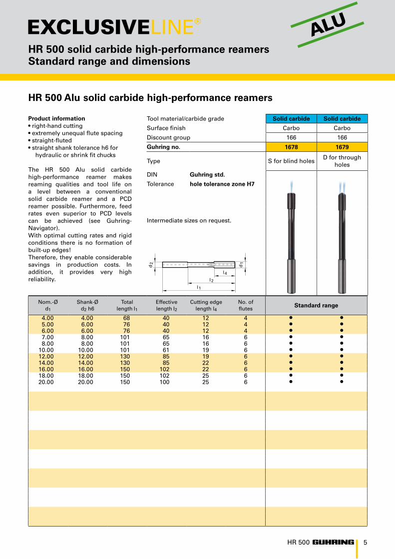
HR 500 solid carbide high-performance reamers Standard range and dimensions
Product information• right-hand cutting• extremely unequal flute spacing• straight-fluted• straight shank tolerance h6 for
hydraulic or shrink fit chucks
The solid carbide HPC reamer HR 500 operates with highest cutting rates (see GuhringNavigator) and pro-duces extremely high-quality holes.Therefore, it enables considerable savings in production costs. In addi-tion, it provides very high process re-liability. The coolant supply ensures an optimal chip evacuation and an optimal cooling.
Tool material/carbide grade Solid carbide Solid carbide
Surface finish TiAlN TiAlN
Discount group 166 166
Guhring no.
Type S for blind holesD for through
holes
DIN Guhring std.
Tolerance hole tolerance zone H7
HR 500 ACTIVEIntermediate sizes and stepped reamers see inquiry form, page 18!
Nom.-Ød1
Shank-Ød2 h6
Totallength l1
Effectivelength l2
Cutting edgelength l4
No. offlutes Standard range
3.00 4.00 68 40 12 4 3.50 4.00 68 40 12 4 4.00 4.00 68 40 12 4 4.50 6.00 76 40 12 4 5.00 6.00 76 40 12 4 5.50 6.00 76 40 12 4 6.00 6.00 76 40 12 4 6.50 8.00 101 65 16 6 7.00 8.00 101 65 16 6 7.50 8.00 101 65 16 6 8.00 8.00 101 65 16 6 8.50 10.00 101 61 19 6 9.00 10.00 101 61 19 6 9.50 10.00 101 61 19 6
10.00 10.00 101 61 19 6 10.50 12.00 130 85 19 6 11.00 12.00 130 85 19 6 11.50 12.00 130 85 19 6 12.00 12.00 130 85 19 6 13.00 14.00 130 85 22 6 14.00 14.00 130 85 22 6 15.00 16.00 150 102 22 6 16.00 16.00 150 102 22 6 17.00 18.00 150 102 25 6 18.00 18.00 150 102 25 6 19.00 20.00 150 100 25 6 20.00 20.00 150 100 25 6
HR 500 solid carbide high-performance reamers
NEW:
from Ø 3.00 mm
5
1678 1679d
2
l 1
d1
l 4
l2
HR 500
HR 500 solid carbide high-performance reamers Standard range and dimensions
Product information• right-hand cutting• extremely unequal flute spacing• straight-fluted• straight shank tolerance h6 for
hydraulic or shrink fit chucks
The HR 500 Alu solid carbide high-performance reamer makes reaming qualities and tool life on a level between a conventional solid carbide reamer and a PCD reamer possible. Furthermore, feed rates even superior to PCD levels can be achieved (see Guhring- Navigator). With optimal cutting rates and rigid conditions there is no formation of built-up edges!Therefore, they enable considerable savings in production costs. In addition, it provides very high reliability.
Tool material/carbide grade Solid carbide Solid carbide
Surface finish Carbo Carbo
Discount group 166 166
Guhring no.
Type S for blind holesD for through
holes
DIN Guhring std.
Tolerance hole tolerance zone H7
Intermediate sizes on request.
Nom.-Ød1
Shank-Ød2 h6
Totallength l1
Effectivelength l2
Cutting edgelength l4
No. offlutes Standard range
4.00 4.00 68 40 12 4 5.00 6.00 76 40 12 4 6.00 6.00 76 40 12 4 7.00 8.00 101 65 16 6 8.00 8.00 101 65 16 6
10.00 10.00 101 61 19 6 12.00 12.00 130 85 19 6 14.00 14.00 130 85 22 6 16.00 16.00 150 102 22 6 18.00 18.00 150 102 25 6 20.00 20.00 150 100 25 6
HR 500 Alu solid carbide high-performance reamers
ALU

6
1675 1676d
2
l 1
d1
l 4
l2
HR 500
HR 500 solid carbide high-performance reamers Standard range and dimensions
HR 500 solid carbide high-performance reamers
Product information• right-hand cutting• extremely unequal flute spacing• straight-fluted• straight shank tolerance h6 for
hydraulic or shrink fit chucks
The solid carbide HPC reamer HR 500 operates with highest cutting rates (see GuhringNavigator) and produces extremely high-quality holes. Therefore, it often enables considerable savings in production costs. In addition, it provides very high process reliability. The coolant supply ensures an optimal chip evacuation and an optimal cooling.
Tool material/carbide grade Solid carbide Solid carbide
Surface finish TiAlN TiAlN
Discount group 166 166
Guhring no.
Type S for blind holesD for through
holes
DIN Guhring std.
Tolerance + 0.005
HR 500 ACTIVEIntermediate sizes and stepped reamers see inquiry form, page 18!
Nom.-Ød1
Shank-Ød2 h6
Totallength l1
Effectivelength l2
Cutting edgelength l4
No. offlutes Standard range
2.97 4.00 68 40 12 4 2.98 4.00 68 40 12 4 2.99 4.00 68 40 12 4 3.00 4.00 68 40 12 4 3.01 4.00 68 40 12 4 3.02 4.00 68 40 12 4 3.03 4.00 68 40 12 4 3.97 4.00 68 40 12 4 3.98 4.00 68 40 12 4 3.99 4.00 68 40 12 4 4.00 4.00 68 40 12 4 4.01 4.00 68 40 12 4 4.02 4.00 68 40 12 4 4.03 4.00 68 40 12 4 4.97 6.00 76 40 12 4 4.98 6.00 76 40 12 4 4.99 6.00 76 40 12 4 5.00 6.00 76 40 12 4 5.01 6.00 76 40 12 4 5.02 6.00 76 40 12 4 5.03 6.00 76 40 12 4 5.97 6.00 76 40 12 4 5.98 6.00 76 40 12 4 5.99 6.00 76 40 12 4 6.00 6.00 76 40 12 4 6.01 6.00 76 40 12 4 6.02 6.00 76 40 12 4 6.03 6.00 76 40 12 4 7.00 8.00 101 65 16 6 7.97 8.00 101 65 16 6 7.98 8.00 101 65 16 6 7.99 8.00 101 65 16 6 8.00 8.00 101 65 16 6
NEW:
from Ø 2.97 mm

7
1675 1676d
2
l 1
d1
l 4
l2
HR 500
HR 500 solid carbide high-performance reamers Standard range and dimensions
Product information• right-hand cutting• extremely unequal flute spacing• straight-fluted• straight shank tolerance h6 for
hydraulic or shrink fit chucks
The solid carbide HPC reamer HR 500 operates with highest cutting rates (see GuhringNavigator) and produces extremely high-quality holes. Therefore, it often enables considerable savings in production costs. In addition, it provides very high process reliability. The coolant supply ensures an optimal chip evacuation and an optimal cooling.
Tool material/carbide grade Solid carbide Solid carbide
Surface finish TiAlN TiAlN
Discount group 166 166
Guhring no.
Type S for blind holesD for through
holes
DIN Guhring std.
Tolerance + 0.005
HR 500 ACTIVEIntermediate sizes and stepped reamers see inquiry form, page 18!
HR 500 solid carbide high-performance reamers
Nom.-Ød1
Shank-Ød2 h6
Totallength l1
Effectivelength l2
Cutting edgelength l4
No. offlutes Standard range
8.01 8.00 101 65 16 6 8.02 8.00 101 65 16 6 8.03 8.00 101 65 16 6 9.00 10.00 101 61 19 6 9.97 10.00 101 61 19 6 9.98 10.00 101 61 19 6 9.99 10.00 101 61 19 6
10.00 10.00 101 61 19 6 10.01 10.00 101 61 19 6 10.02 10.00 101 61 19 6 10.03 10.00 101 61 19 6 11.00 12.00 130 85 19 6 11.97 12.00 130 85 19 6 11.98 12.00 130 85 19 6 11.99 12.00 130 85 19 6 12.00 12.00 130 85 19 6 12.01 12.00 130 85 19 6 12.02 12.00 130 85 19 6 12.03 12.00 130 85 19 6

8
HR 500
HR 500 solid carbide high-performance reamers GuhringNavigator
Tools with bold feed column no. are preferred choice.
HR 500 reamers up to 20.00 mm
soluble oilneat oilair
Coolant:
Material group Material examples Tensile strength Cool-antFigures in bold = material no. to DIN EN 10 027 N/mm2
Common structural steels 1.0035 S185, 1.0486 StE P275N, 1.0345 P235GH, 1.0425 P265GH ≤5001.0050 E295, 1.0070 E360, 1.8937 P500NH >500-850
Free-cutting steels 1.0718 11SMnPb30, 1.0736 115Mn37 ≤8501.0727 46 S20, 1.0728 60 S20, 1.0757 46SPb20 850-1000
Unalloyed heat-treatable steels 1.0402 C22, 1.1178 C30E ≤ 7001.0503 C45, 1.1191 C45E 700-8501.0601 C60, 1.1221 C60E 850-1000
Alloyed heat-treatable steels 1.5131 50MnSi4, 1.7003 38Cr2, 1.7030 28Cr4 850-10001.5710 36NiCr6, 1.7035 41Cr4, 1.7225 42CrMo4 1000-1200
Unalloyed case hardened steels 1.0301 C10, 1.1121 C10E ≤750Alloyed case hardened steels 1.7043 38Cr4 850-1000
1.5752 14NiCr14, 1.7131 16MnCr5, 1.7264 20CrMo5 1000-1200Nitriding steels 1.8504 34CrAl6 ≥850-1000
1.8519 31CrMoV9, 1.8550 34CrAlNi7 1000-1200Tool steels 1.1750 C75W, 1.2067 102Cr6, 1.2307 29CrMoV9 ≤850
1.2080 X210Cr12, 1.2083 X42Cr13, 1.2419 105WCr6, 1.2767 X45NiCrMo4 850-1000High speed steels 1.3243 S 6-5-2-5, 1.3343 S 6-5-2, 1.3344 61CrV4 ≥650-1000Spring steels 1.5026 55Si7, 1.7176 55Cr3, 1.8159 51CrV4 ≥330 HBStainless steels, sulphured 1.4005 X12CrS13, 1.4104 X14CrMoS17, 1.4105 X6CrMoS17, 1.4305 ≤850austenitic 1.4301 X5CrNi18 10, 1.4541 X6CrNiTi18 10, 1.4571 X6CrNiMoTi 17 12 2 ≤850martensitic 1.4057 X17CrNi16-1, 1.4122 X39CrMo17-1, 1.4521 X2CrMoTi18 2 ≤850Hardened steels – ≤40-48 HRC
>48-62 HRCSpecial alloys Nimonic, Inconel, Monel, Hastelloy ≤1200Cast iron 0.6010 EN-GJL-100 (GG10) 0.6020 EN-GJL-200 (GG20) ≤240 HB
0.6025 EN-GJL-250 (GG25) 0.6035 EN-GJL-350 (GG35) <300 HBSpheroidal graphite and 0.7050 EN-GJS-500-7 (GGG50) 0.8035 EN-GJMW-350-4 (GTW5) ≤240 HBmalleable cast iron 0.7060 EN-GJS-600-3 (GGG60) 0.7070 EN-GJS-700-2 (GGG70) <300 HBChilled cast iron – ≤350 HBTi and Ti-alloys 3.7024 Ti99,5, 3.7114 TiAl5Sn2,5, 3.7124 TiCu2 ≤850
3.7154 TiAl6Zr5, 3.7164 TiAl6V4, 3.7184 TiAl4Mo4Sn2,5, - TiAl8Mo1V1 850-1200Aluminium and Al-alloys 3.0255 Al99,5, 3.2315 AlMgSi1, 3.3515 AlMg1 ≤400Al wrought alloys ≤450Al cast iron ≤ 10 % Si 3.2131 G-AlSi5Cu1, 3.2153 G-AlSi7Cu3, 3.2573 G-AlSi9 ≤600
> 10 % Si 3.2581 G-AlSi12, 3.2583 G-AlSi12Cu, - G-AlSi12CuNiMg ≤600Magnesium alloys MgMn2, G-MgAl8Zn1, G-MgAl6Zn3 ≤450Copper, low-alloyed 2.0070 SE-Cu, 2.1020 CuSn6, 2.1096 G-CuSn5ZnPb ≤400Brass, short-chipping 2.0380 CuZn39Pb2, 2.0401 CuZn39Pb3, 2.0410 CuZn43Pb2 ≤600 long-chipping 2.0250 CuZn20, 2.0280 CuZn33, 2.0332 CuZn37Pb0,5 ≤600Bronze, short-chipping 2.1090 CuSn7ZnPb, 2.1170 CuPb5Sn5, 2.1176 CuPb10Sn ≤600
2.0790 CuNi18Zn19Pb >600-850Bronze, long-chipping 2.0916 CuAl5, 2.0960 CuAl9Mn, 2.1050 CuSn10 ≤850
2.0980 CuAl11Ni, 2.1247 CuBe2 850-1000Duroplastics Bakelit, Resopal, Pertinax, MoltoprenThermoplastics Plexiglass, Hostalen, Novodur, MakralonKevlar KevlarGlass/carbon fibre reinf. plastics GFP/CFP
Tool material/Carbide grade Carb./K10
Surface finish TiAlN
Guhring no. 1685 1686
Guhring no. 1675 1676
vcm/min
Feed column no.
120-250 75-76120-250 75-76120-250 75-76120-250 75-76120-250 75-76120-250 75-76120-250 75-76120-250 75-76120-250 75-76120-250 75-76120-250 75-76120-250 75-76120-250 75-76120-250 75-76120-250 75-76120-250 75-7660-120 75-7630-60 73-7460-120 74-7540-80 74-7560-120 74-7540-60 73-7430-60 73-7440-60 74-7560-140 75-7660-140 75-76
120-250 75-7660-120 75-7630-50 74-7540-80 74-7540-80 74-75
80-160 75-76
100-250 75-76
100-250 75-76100-250 75-76
80-200 75-7680-200 75-7680-200 75-7680-200 75-76
Reamer-Ø
mm
Feed column no.71 72 73 74 75 76 77
f (mm/rev.)< 4.00 0.080 0.100 0.125 0.300 0.500 0.800 1.000
4.00 0.100 0.125 0.160 0.300 0.500 1.000 1.2005.00 0.100 0.125 0.160 0.400 0.600 1.000 1.4006.30 0.125 0.160 0.200 0.400 0.700 1.200 1.6008.00 0.160 0.200 0.250 0.600 1.000 1.800 2.400
10.00 0.200 0.250 0.315 0.600 1.200 1.800 2.40012.50 0.200 0.250 0.315 0.800 1.200 2.000 2.50016.00 0.250 0.315 0.400 0.800 1.400 2.200 2.60020.00 0.315 0.400 0.500 0.800 1.400 2.200 2.60025.00 0.400 0.500 0.630 1.000 1.600 2.500 3.00031.50 0.400 0.500 0.630 1.000 2.000 3.000 3.60040.00 0.500 0.630 0.800 1.200 2.000 3.000 3.60050.00 0.630 0.800 1.000 1.400 2.200 3.200 3.600
> 50.00 0.800 1.000 1.250 1.600 2.200 3.200 3.600
For an optimal cooling lubricant supply to HR 500 type D reamer cutting edges for through holes we recommend clamping in hydraulic or shrink fit chucks to the maximum clamping depth.

9
HR 500
HR 500 solid carbide high-performance reamers Application examples and special solutions
Tool type HR 500 S HR 500 D HR 500 D HR 500 S
Guhring no. 1685 1686special reamer
for tighter tolerances
1685
component machined hinge ring valve body ring
workpiece material gen. steel alloyed steel gen. steel alloyed steel
hole diameter (mm) 9 8 5.9 15
hole tolerance H7 H7 H6 IT 5
reaming depth (mm) 30 25 48 20
cutting speed vc (m/min.)
120 200 190 250
feed rate vf (mm/min.)
4200 12700 6100 7200
tool life (m) 60 100 55 70
Application examples for Guhring‘s new HR 500 S and HR 500 D solid carbide high-performance reamers with highest feed rates and tool life
The new HR 500 S and HR 500 D solid carbide high-performance reamers have shown their performance in several applications, see following table:
Hard reaming instead of eroding:Enormous savings thanks to HR 500
Guhring’s HR 500 high performance reamers are not only first choice for volume production. They are also the ideal solution for especially demanding machining tasks.They replace the expensive eroding operation of highly accurate ejector bores in hardened steel. Advantage for the customer: The machining time of in excess of 30 minutes per bore for eroding is reduced to less than 1 second with hard reaming.
vcm/min
Feed column no.
200-400 76-77200-400 76-77200-400 76-77200-400 76-77
Carb./K10
Carbo
1678
1679
10 HR 500
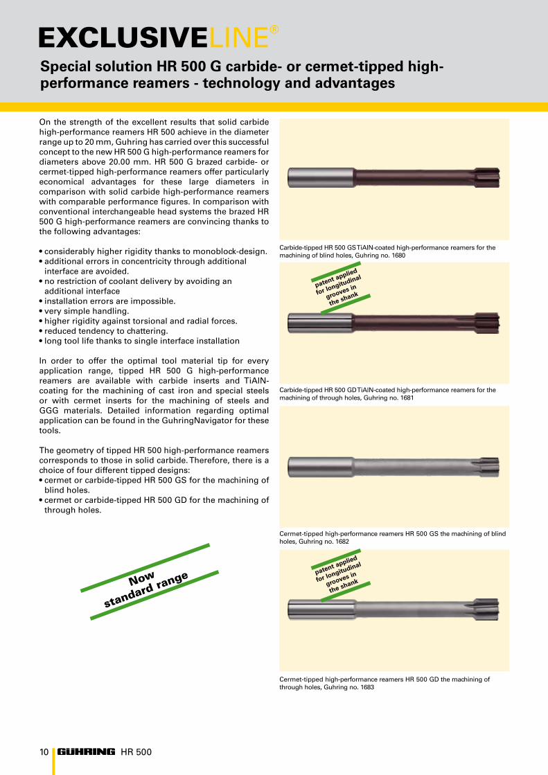
On the strength of the excellent results that solid carbide high-performance reamers HR 500 achieve in the diameter range up to 20 mm, Guhring has carried over this successful concept to the new HR 500 G high-performance reamers for diameters above 20.00 mm. HR 500 G brazed carbide- or cermet-tipped high-performance reamers offer particularly economical advantages for these large diameters in comparison with solid carbide high-performance reamers with comparable performance figures. In comparison with conventional interchangeable head systems the brazed HR 500 G high-performance reamers are convincing thanks to the following advantages:
• considerably higher rigidity thanks to monoblock-design.• additional errors in concentricity through additional
interface are avoided.• no restriction of coolant delivery by avoiding an
additional interface• installation errors are impossible.• very simple handling.• higher rigidity against torsional and radial forces.• reduced tendency to chattering. • long tool life thanks to single interface installation
In order to offer the optimal tool material tip for every application range, tipped HR 500 G high-performance reamers are available with carbide inserts and TiAlN-coating for the machining of cast iron and special steels or with cermet inserts for the machining of steels and GGG materials. Detailed information regarding optimal application can be found in the GuhringNavigator for these tools.
The geometry of tipped HR 500 high-performance reamers corresponds to those in solid carbide. Therefore, there is a choice of four different tipped designs:• cermet or carbide-tipped HR 500 GS for the machining of
blind holes. • cermet or carbide-tipped HR 500 GD for the machining of
through holes.
Special solution HR 500 G carbide- or cermet-tipped high-performance reamers - technology and advantages
Carbide-tipped HR 500 GD TiAlN-coated high-performance reamers for the machining of through holes, Guhring no. 1681
Cermet-tipped high-performance reamers HR 500 GD the machining of through holes, Guhring no. 1683
Carbide-tipped HR 500 GS TiAlN-coated high-performance reamers for the machining of blind holes, Guhring no. 1680
Cermet-tipped high-performance reamers HR 500 GS the machining of blind holes, Guhring no. 1682
Now
standard range
patent applied
for longitudinal
grooves in
the shank
patent applied
for longitudinal
grooves in
the shank

11HR 500
Special solution HR 500 G carbide- or cermet-tipped high-performance reamers - special designs
Carbide- or cermet-tipped HR 500 high-performance reamers are available in preferred sizes as standard range. In addition we manufacture special tools to customer specifications on request.
Even for diameters above 40 mm Guhring‘s HR 500 techno-logy is the first choice for high-performance reaming. The secure clamping of the tool head with HA shank in hydrau-lic chucks ensures maximum precision and quality, hand-ling is easy and flexible.
For application in deep holes the clamping is possible in elongated hydraulic chucks, for short reaming depths use standard chucks.

12
1680 1681d
2
d1
l 2
l1
l4
HR 500
HR 500 G high-performance reamers Standard range and dimensions
HR 500 G carbide-tipped high-performance reamers
Product information• right-hand cutting• extremely unequal flute spacing• straight-fluted• straight shank tolerance h6 for
hydraulic or shrink fit chucks
The carbide-tipped HPC reamer HR 500 G operates at highest cutting rates (see GuhringNavigator) and produces extremely high-quality holes. Therefore, it often enables considerable savings in production costs. In addition, it provides very high process reliability. The coolant supply ensures an optimal chip evacuation and an optimal cooling.
Tool material/carbide grade Carbide Carbide
Surface finish TiAlN TiAlN
Discount group 166 166
Guhring no.
Type S for blind holesD for through
holes
DIN Guhring std.
Tolerance hole tolerance zone H7
Intermediate sizes from Ø 20.1 mm available for fast delivery.
Nom.-Ød1 H7
Shank-Ød2
Total length l1
Effective length l2
Cutting edgelength l4
zStandard range
22.00 20 160 110 22 6 24.00 25 180 124 22 6 25.00 25 180 124 22 6 26.00 25 180 124 22 6 28.00 25 180 124 25 6 30.00 25 180 124 25 6 32.00 32 200 140 25 6 34.00 32 200 140 25 6 36.00 32 200 140 25 8 38.00 32 200 140 25 8 40.00 32 200 140 25 8

13
d2
d1
l 2
l1
l4
1682 1683
HR 500
HR 500 G high-performance reamers Standard range and dimensions
HR 500 G cermet-tipped high-performance reamers
Product information• right-hand cutting• extremely unequal flute spacing• straight-fluted• straight shank tolerance h6 for
hydraulic or shrink fit chucks
The HR 500 G cermet-tipped HPC reamer operates at highest cutting rates (see GuhringNavigator) and produces extremely high-quality holes. Therefore, it often enables considerable savings in production costs. In addition, it provides very high process reliability. The coolant supply ensures an optimal chip evacu-ation and an optimal cooling.
Tool material/carbide grade Cermet Cermet
Surface finish bright bright
Discount group 166 166
Guhring no.
Type S for blind holesD for through
holes
DIN Guhring std.
Tolerance hole tolerance zone H7
Intermediate sizes from Ø 20.1 mm available for fast delivery.
Nom.-Ød1 H7
Shank-Ød2
Total length l1
Effective length l2
Cutting edgelength l4
zStandard range
22.00 20 160 110 22 6 24.00 25 180 124 22 6 25.00 25 180 124 22 6 26.00 25 180 124 22 6 28.00 25 180 124 25 6 30.00 25 180 124 25 6 32.00 32 200 140 25 6 34.00 32 200 140 25 6 36.00 32 200 140 25 8 38.00 32 200 140 25 8 40.00 32 200 140 25 8

14
HR 500
vcm/min
Feed column no.
25-40 74-7525-40 74-7525-40 74-7525-40 74-7525-40 74-7525-40 74-7525-40 74-7525-40 74-7525-40 74-7525-40 74-7525-40 74-7525-40 74-7525-40 74-7525-40 74-7525-40 74-7525-40 74-7520-30 74-7520-30 74-7530-60 74-7520-30 74-7520-30 74-7510-20 72-73
20-30 73-7440-100 75-7640-100 75-7650-120 75-7650-100 75-7620-40 74-7520-40 73-7420-40 73-74
80-160 75-76
40-120 74-7540-120 74-7550-120 74-7550-120 74-7550-120 74-7550-120 74-7540-120 74-7540-120 74-7540-120 74-7540-120 74-75
Tool material/Carbide grade Carb./K10
Surface finish TiAlN
Guhring no. 1680
Guhring no. 1681
HR 500 G high performance reamers GuhringNavigator and application examples
Tools with bold feed column no. are preferred choice.
HR 500 Reamers from Ø 20.00 mm up to 40.00 mm
soluble oilneat oilair
Coolant:
Material group Material examples Tensile strength Cool-antFigures in bold = material no. to DIN EN 10 027 N/mm2
Common structural steels 1.0035 S185, 1.0486 StE P275N, 1.0345 P235GH, 1.0425 P265GH ≤5001.0050 E295, 1.0070 E360, 1.8937 P500NH >500-850
Free-cutting steels 1.0718 11SMnPb30, 1.0736 115Mn37 ≤8501.0727 46 S20, 1.0728 60 S20, 1.0757 46SPb20 850-1000
Unalloyed heat-treatable steels 1.0402 C22, 1.1178 C30E ≤ 7001.0503 C45, 1.1191 C45E 700-8501.0601 C60, 1.1221 C60E 850-1000
Alloyed heat-treatable steels 1.5131 50MnSi4, 1.7003 38Cr2, 1.7030 28Cr4 850-10001.5710 36NiCr6, 1.7035 41Cr4, 1.7225 42CrMo4 1000-1200
Unalloyed case hardened steels 1.0301 C10, 1.1121 C10E ≤750Alloyed case hardened steels 1.7043 38Cr4 850-1000
1.5752 14NiCr14, 1.7131 16MnCr5, 1.7264 20CrMo5 1000-1200Nitriding steels 1.8504 34CrAl6 ≥850-1000
1.8519 31CrMoV9, 1.8550 34CrAlNi7 1000-1200Tool steels 1.1750 C75W, 1.2067 102Cr6, 1.2307 29CrMoV9 ≤850
1.2080 X210Cr12, 1.2083 X42Cr13, 1.2419 105WCr6, 1.2767 X45NiCrMo4 850-1000High speed steels 1.3243 S 6-5-2-5, 1.3343 S 6-5-2, 1.3344 61CrV4 ≥650-1000Spring steels 1.5026 55Si7, 1.7176 55Cr3, 1.8159 51CrV4 ≥330 HBStainless steels, sulphured 1.4005 X12CrS13, 1.4104 X14CrMoS17, 1.4105 X6CrMoS17, 1.4305 ≤850austenitic 1.4301 X5CrNi18 10, 1.4541 X6CrNiTi18 10, 1.4571 X6CrNiMoTi 17 12 2 ≤850martensitic 1.4057 X17CrNi16-1, 1.4122 X39CrMo17-1, 1.4521 X2CrMoTi18 2 ≤850Hardened steels – ≤40-48 HRC
>48-62 HRCSpecial alloys Nimonic, Inconel, Monel, Hastelloy ≤1200Cast iron 0.6010 EN-GJL-100 (GG10) 0.6020 EN-GJL-200 (GG20) ≤240 HB
0.6025 EN-GJL-250 (GG25) 0.6035 EN-GJL-350 (GG35) <300 HBSpheroidal graphite and 0.7050 EN-GJS-500-7 (GGG50) 0.8035 EN-GJMW-350-4 (GTW5) ≤240 HBmalleable cast iron 0.7060 EN-GJS-600-3 (GGG60) 0.7070 EN-GJS-700-2 (GGG70) <300 HBChilled cast iron – ≤350 HBTi and Ti-alloys 3.7024 Ti99,5, 3.7114 TiAl5Sn2,5, 3.7124 TiCu2 ≤850
3.7154 TiAl6Zr5, 3.7164 TiAl6V4, 3.7184 TiAl4Mo4Sn2,5, - TiAl8Mo1V1 850-1200Aluminium and Al-alloys 3.0255 Al99,5, 3.2315 AlMgSi1, 3.3515 AlMg1 ≤400Al wrought alloys ≤450Al cast iron ≤ 10 % Si 3.2131 G-AlSi5Cu1, 3.2153 G-AlSi7Cu3, 3.2573 G-AlSi9 ≤600
> 10 % Si 3.2581 G-AlSi12, 3.2583 G-AlSi12Cu, - G-AlSi12CuNiMg ≤600Magnesium alloys MgMn2, G-MgAl8Zn1, G-MgAl6Zn3 ≤450Copper, low-alloyed 2.0070 SE-Cu, 2.1020 CuSn6, 2.1096 G-CuSn5ZnPb ≤400Brass, short-chipping 2.0380 CuZn39Pb2, 2.0401 CuZn39Pb3, 2.0410 CuZn43Pb2 ≤600 long-chipping 2.0250 CuZn20, 2.0280 CuZn33, 2.0332 CuZn37Pb0,5 ≤600Bronze, short-chipping 2.1090 CuSn7ZnPb, 2.1170 CuPb5Sn5, 2.1176 CuPb10Sn ≤600
2.0790 CuNi18Zn19Pb >600-850Bronze, long-chipping 2.0916 CuAl5, 2.0960 CuAl9Mn, 2.1050 CuSn10 ≤850
2.0980 CuAl11Ni, 2.1247 CuBe2 850-1000Duroplastics Bakelit, Resopal, Pertinax, MoltoprenThermoplastics Plexiglass, Hostalen, Novodur, MakralonKevlar KevlarGlass/carbon fibre reinf. plastics GFP/CFP
Reamer-Ø
mm
Feed column no.71 72 73 74 75 76 77
f (mm/rev.)< 4.00 0.080 0.100 0.125 0.300 0.500 0.800 1.000
4.00 0.100 0.125 0.160 0.300 0.500 1.000 1.2005.00 0.100 0.125 0.160 0.400 0.600 1.000 1.4006.30 0.125 0.160 0.200 0.400 0.700 1.200 1.6008.00 0.160 0.200 0.250 0.600 1.000 1.800 2.400
10.00 0.200 0.250 0.315 0.600 1.200 1.800 2.40012.50 0.200 0.250 0.315 0.800 1.200 2.000 2.50016.00 0.250 0.315 0.400 0.800 1.400 2.200 2.60020.00 0.315 0.400 0.500 0.800 1.400 2.200 2.60025.00 0.400 0.500 0.630 1.000 1.600 2.500 3.00031.50 0.400 0.500 0.630 1.000 2.000 3.000 3.60040.00 0.500 0.630 0.800 1.200 2.000 3.000 3.60050.00 0.630 0.800 1.000 1.400 2.200 3.200 3.600
> 50.00 0.800 1.000 1.250 1.600 2.200 3.200 3.600
For an optimal cooling lubricant supply to HR 500 type D reamer cutting edges for through holes we recommend clamping in hydraulic or shrink fit chucks to the maximum clamping depth.

15
HR 500
vcm/min
Feed column no.
100-180 75-76100-180 75-76100-180 75-76100-180 75-76100-180 75-76100-180 75-76100-180 75-76100-180 75-76100-180 75-76100-180 75-76100-180 75-76100-180 75-76100-180 75-76100-180 75-76100-180 75-76100-180 75-76
100-120 74-75
80-150 75-76
Cermet
bright
1682
1683
HR 500 G high-performance reamers GuhringNavigator and application examples
Application examples for Guhring special high-performance reamers HR 500 G
Carbide- or cermet-tipped special high-performance reamers HR 500 GS and HR 500 GD have already been able to demonstrate their efficiency in numerous applications. The following table contains some examples.
Tool type HR 500 GD HR 500 GD HR 500 GD
Guhring no. 1683 (shortened) 1681 1683
tool material/coating cermet carbide + TiAlN cermet
component machined universal joint wheel flange differential housing
workpiece material steel cast iron cast iron
hole diameter (mm) 25 22 32
hole tolerance F7 H8 H7
reaming depth (mm) 18 20 50
Cutting speed
Vc (m/min) 130 120 120
Feed rate
Vf (mm/min) 2000 2600 3000
tool life (m) 175 120 160

16 HR 500
Ever since their introduction, Guhring‘s solid carbide high-performance reamers HR 500 D for through holes and HR 500 S for blind holes have impressed customers with their outstanding performance. Even under difficult machining conditions such as interrupted cutting or unstable machines they ream holes at cutting rates higher than cermet levels with maximum tool life and optimal quality in almost all materials.
So the user can also fully utilise
the advantages of HR 500 high-performance reamers for the machining of the special applications Guhring has developed the HR 500 ACTIVE range: Special tools based on HR 500 technology for cylindrical and stepped holes There is a choice of four HR 500 ACTIVE types:- for cylindrical blind holes- for cylindrical through holes- for stepped blind holes - for stepped through holes
The four HR 500 ACTIVE types are
available in the following designs: - with or without internal cooling- short or long version- with TiAlN coating or bright finish- to hole tolerance or reamer manufacturing tolerance
You have the choice of designing the optimal HR 500 reamer for your specific application! Simply complete the questionnaire and send or fax it to the address or fax number respectively.
Your ACTIVE advantages:
+ perfect adaptation of tool material, geometry and coating to workpiece material and hole+ with internal cooling: central coolant duct for blind holes, longitudinal grooves in shank for through holes+ nominal diameter from 2.95 up to 20.1 mm+ shank to DIN 6535 HA+ tolerances to requirements for the perfect finish+ available in long or short version+ highest quality+ best cost-performance ratio+ delivery time: maximum 3 weeks for TiAlN-coated tools and maximum 2 weeks for bright finish tools
Perfect finish thanks to closest tolerances!
It‘s your choice! We produce perfect quality for you in the shortest time possible: + we produce your required hole tolerance to DIN 1420.+ reamers with manufacturing tolerances according to your requirements!
The minimum manufacturing tolerance is 0.005 mm, applies to both diameters with step reamers!
General conditions for HR 500 ACTIVE step reamers
With HR 500 ACTIVE step reamers please note the following pre-requisites:+ the minimum step differential is 0.2 mm.+ the countersink angle W1 can be chosen between 40° and 180° (± 1°). With 180° countersink angle the outer cutting edge has a corner chamfer 0.1+0.1x45°.
Optimal clamping holders from our current GM 300 range:+ hydraulic chucks+ shrink fit chucks
Quotationwithin 72hrs!
Tool dispatchmaximum 4 weeks
HR 500 ACTIVE Special range of HR 500 solid carbide high-performance reamers

17
AA
AA
A
A
A
AA
A
AA
AA
AA
A
A
A
A
A
AA
A
AA
AA
A
A
A
AA
AA
AA
A
HR 500
vc FCm/min no.
120-250 75-76120-250 75-76120-250 75-76120-250 75-76120-250 75-76120-250 75-76120-250 75-76120-250 75-76120-250 75-76120-250 75-76120-250 75-76120-250 75-76120-250 75-76120-250 75-76120-250 75-76120-250 75-7660-120 75-7630-60 73-7460-120 74-7540-80 74-7560-120 74-7540-60 73-7430-60 73-7440-60 74-7560-140 75-7660-140 75-76
120-250 75-7660-120 75-7630-50 74-7530-80 74-7530-80 74-75
80-160 75-76
100-250 75-76
100-250 75-76100-250 75-76
80-200 75-7680-200 75-7680-200 75-7680-200 75-76
Sur-face
Tools with bold feed column no. are preferred choice.
soluble oilneat oilair
Coolant:
Material group Material examples, new description (old description in brackets) Tensile strength Cool-Figures in bold = material no. to DIN EN 10 027 N/mm2 ant
Common structural steels 1.0035 S185, 1.0486 StE P275N, 1.0345 P235GH, 1.0425 P265GH ≤5001.0050 E295, 1.0070 E360, 1.8937 P500NH >500-850
Free-cutting steels 1.0718 11SMnPb30, 1.0736 115Mn37 ≤8501.0727 46 S20, 1.0728 60 S20, 1.0757 46SPb20 850-1000
Unalloyed heat-treatable steels 1.0402 C22, 1.1178 C30E ≤ 7001.0503 C45, 1.1191 C45E 700-8501.0601 C60, 1.1221 C60E 850-1000
Alloyed heat-treatable steels 1.5131 50MnSi4, 1.7003 38Cr2, 1.7030 28Cr4 850-10001.5710 36NiCr6, 1.7035 41Cr4, 1.7225 42CrMo4 1000-1200
Unalloyed case hardened steels 1.0301 C10, 1.1121 C10E ≤750Alloyed case hardened steels 1.7043 38Cr4 850-1000
1.5752 14NiCr14, 1.7131 16MnCr5, 1.7264 20CrMo5 1000-1200Nitriding steels 1.8504 34CrAl6 ≥850-1000
1.8519 31CrMoV9, 1.8550 34CrAlNi7 1000-1200Tool steels 1.1750 C75W, 1.2067 102Cr6, 1.2307 29CrMoV9 ≤850
1.2080 X210Cr12, 1.2083 X42Cr13, 1.2419 105WCr6, 1.2767 X45NiCrMo4 850-1000High speed steels 1.3243 S 6-5-2-5, 1.3343 S 6-5-2, 1.3344 61CrV4 ≥650-1000Spring steels 1.5026 55Si7, 1.7176 55Cr3, 1.8159 51CrV4 ≥330 HBStainless steels, sulphured 1.4005 X12CrS13, 1.4104 X14CrMoS17, 1.4105 X6CrMoS17, 1.4305 ≤850
austenitic 1.4301 X5CrNi18 10, 1.4541 X6CrNiTi18 10, 1.4571 X6CrNiMoTi 17 12 2 ≤850martensitic 1.4057 X17CrNi16-1, 1.4122 X39CrMo17-1, 1.4521 X2CrMoTi18 2 ≤850
Hardened steels – ≤40-48 HRC>48-62 HRC
Special alloys Nimonic, Inconel, Monel, Hastelloy ≤1200Cast iron 0.6010 EN-GJL-100 (GG10) 0.6020 EN-GJL-200 (GG20) ≤240 HB
0.6025 EN-GJL-250 (GG25) 0.6035 EN-GJL-350 (GG35) <300 HBSpheroidal graphite and 0.7050 EN-GJS-500-7 (GGG50) 0.8035 EN-GJMW-350-4 (GTW5) ≤240 HBmalleable cast iron 0.7070 EN-GJS-700-2 (GGG70) 0.8170 EN-GJMB-700-2 (GTS70) <300 HBChilled cast iron – ≤350 HBTi and Ti-alloys 3.7024 Ti99,5, 3.7114 TiAl5Sn2,5, 3.7124 TiCu2 ≤850
3.7154 TiAl6Zr5, 3.7164 TiAl6V4, 3.7184 TiAl4Mo4Sn2,5, - TiAl8Mo1V1 850-1200Aluminium and Al-alloys 3.0255 Al99,5, 3.2315 AlMgSi1, 3.3515 AlMg1 ≤400Al-wrought alloys ≤450Al-cast alloys ≤ 10 % Si 3.2131 G-AlSi5Cu1, 3.2153 G-AlSi7Cu3, 3.2573 G-AlSi9 ≤600
> 10 % Si 3.2581 G-AlSi12, 3.2583 G-AlSi12Cu, - G-AlSi12CuNiMg ≤600Magnesium-alloys MgMn2, G-MgAl8Zn1, G-MgAl6Zn3 ≤450Copper, low-alloyed 2.0070 SE-Cu, 2.1020 CuSn6, 2.1096 G-CuSn5ZnPb ≤400Brass, short-chipping 2.0380 CuZn39Pb2, 2.0401 CuZn39Pb3, 2.0410 CuZn43Pb2 ≤600
long-chipping 2.0250 CuZn20, 2.0280 CuZn33, 2.0332 CuZn37Pb0,5 ≤600Bronze, short-chipping 2.1090 CuSn7ZnPb, 2.1170 CuPb5Sn5, 2.1176 CuPb10Sn ≤600
2.0790 CuNi18Zn19Pb >600-850Bronze, long-chipping 2.0916 CuAl5, 2.0960 CuAl9Mn, 2.1050 CuSn10 ≤850
2.0980 CuAl11Ni, 2.1247 CuBe2 850-1000Duroplastics Bakelite, Resopal, Pertinax, MoltoprenThermoplastics Plexiglass, Hostalen, Novodur, MakralonKevlar KevlarGlass/carbon fibre reinf. plastics GFP/CFP
Tool material/carbide grade Carb./K10
Form -
bright
TiAlN
HR 500 ACTIVE Cutting rates on the highest level
Reamer-Ø
mm
Feed column no.71 72 73 74 75 76 77
f (mm/rev.)< 4.00 0.080 0.100 0.125 0.300 0.500 0.800 1.000
4.00 0.100 0.125 0.160 0.300 0.500 1.000 1.2005.00 0.100 0.125 0.160 0.400 0.600 1.000 1.4006.30 0.125 0.160 0.200 0.400 0.700 1.200 1.6008.00 0.160 0.200 0.250 0.600 1.000 1.800 2.400
10.00 0.200 0.250 0.315 0.600 1.200 1.800 2.40012.50 0.200 0.250 0.315 0.800 1.200 2.000 2.50016.00 0.250 0.315 0.400 0.800 1.400 2.200 2.60020.00 0.315 0.400 0.500 0.800 1.400 2.200 2.60025.00 0.400 0.500 0.630 1.000 1.600 2.500 3.00031.50 0.400 0.500 0.630 1.000 2.000 3.000 3.60040.00 0.500 0.630 0.800 1.200 2.000 3.000 3.60050.00 0.630 0.800 1.000 1.400 2.200 3.200 3.600
> 50.00 0.800 1.000 1.250 1.600 2.200 3.200 3.600
For an optimal cooling lubricant supply to HR 500 type D reamer cutting edges for through holes we recommend clamping in hydraulic or shrink fit chucks to the maximum clamping depth.

18
Ød
2 h
6
60°l2
l1
Ød
1
lA
l2
l1
Ød
2 h
6
Ød
1
Ø 12Ø 12 F8
Ø 12
HR 500
www.guehring.de
+0.03+0.01
+0.008+0.002
HR 500 ACTIVE Reamers in special dimensions
Quantity
Name/customer no. if available Order no.New customer
Telephone Fax
Street no. Town/post code
Date Signature
Contact for questionsOrder Inquiry
Minimum order quantity 5 tools
Blind hole
Through hole
Hole Ø / tol.
or
Reamersmanufact. Ø / tol.
long version
with internal cooling
short version
without internal cooling
Dimensions
Coating
Material
with internal cooling for blind holes
patent applied for longitudinal grooves in the shank for through holes (with IC)
Steel/hardened steels/ GGG/VA
TiAlN (optimal for machining cast iron and steel)
GG
bright (optimal for machining titanium)
long version short version
Nom.-Ø [mm]from – to d1
l1 Reachl2
l1 Reachl2
Chamfer length la(only blind holes)
Shank-Ø h6 DIN 6535 d2
2.950 – 4.1 68 40 - - 0.4 4
4.101 – 6.1 76 40 - - 0.4 6
6.101 – 8.1 101 65 76 40 0.4 8
8.101 – 10.1 101 61 76 36 0.4 10
10.101 – 12.1 130 85 80 35 0.5 12
12.101 – 14.1 130 85 90 45 0.5 14
14.101 – 16.1 150 102 90 42 0.5 16
16.101 – 18.1 150 102 100 52 0.5 18
18.101 – 20.1 150 100 100 50 0.5 20
central bore
one coolant groove per cutting edge
Nom.-Ø d1
Nom.-Ø d1
Tolerance
upper/lower limit
Example
Example
Example
Further dimensionson request
19
60°
Ød
1
Ød
3
Ød
2 h
6
W1
l2
l1
l3
lA
W1
l2
l1
l3
Ød
2 h
6 Ød
3
Ød
1
Ø 12 F8 Ø 10 H7 Ø 12 Ø 10
Ø 12 Ø 10
HR 500
www.guehring.de
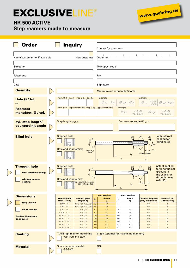
HR 500 ACTIVE Step reamers made to measure
Quantity
Blind hole
Through hole
Name/customer no. if available Order no.New customer
Telephone Fax
Street no. Town/post code
Date Signature
Contact for questionsOrder Inquiry
Hole Ø / tol.or
Reamersmanufact. Ø / tol.
cyl. step length/countersink angle
long version
with internal cooling
short version
without internal cooling
Dimensions
Coating
Material
Minimum order quantity 5 tools
with internal cooling for blind holes
patent applied for longitudinal grooves in the shank for through holes (with IC)
Step length l3 ±0.1
Steel/hardened steels/ GGG/VA
TiAlN (optimal for machining cast iron and steel)
Countersink angle W1 ±1°
GG
bright (optimal for machining titanium)
long version short version
Nom.-Ø [mm]from – to d1
smallest poss. step-Ø d3
l1 Reachl2
l1 Reachl2
Chamfer length la(only blind holes)
Shank-Ø h6 DIN 6535 d2
2.950 – 4.1 d1x0.7 (min.Ø2.95) 68 40 - - 0.4 4
4.101 – 6.1 d1x0.7 (min.Ø2.95) 76 40 - - 0.4 6
6.101 – 8.1 d1 x 0.8 101 65 76 40 0.4 8
8.101 – 10.1 d1 x 0.8 101 61 76 36 0.4 10
10.101 – 12.1 d1 x 0.8 130 85 80 35 0.5 12
12.101 – 14.1 d1 x 0.8 130 85 90 45 0.5 14
14.101 – 16.1 d1 x 0.8 150 102 90 42 0.5 16
16.101 – 18.1 d1 x 0.8 150 102 100 52 0.5 18
18.101 – 20.1 d1 x 0.8 150 100 100 50 0.5 20
central bore
one coolant groove per cutting edge
Stepped hole
Stepped hole
Hole and countersink
Hole and countersink
nom.-Ø d1 tol. d1 step Ø d3 tol. d3
nom.-Ø d1 upper/lower limit step Ø d3 upper/lower limit
Example Example
+0.02-0.004 ±0.2
Example
+0.01-0.004 +0.01-0.004
Further dimensionson request

30
23
9
29
2827 26
25
24
22
21
20
1918
16
1715
14
13
111210
8
7
6
5
3
4
2
1
146
920/
1126
-VIII
-25
• P
rin
ted
in G
erm
any
• 20
11
No liability can be accepted for printing errors or technical changes of any kind.Our Conditions of Sale and Terms of Payment apply. Available on request.
Our service centers
1 Germany Albstadt Berlin Chemnitz Eisenach Geislingen Gosheim Mindelheim Saarbrücken
2 Australia3 Brazil - Diadema4 Brazil - Joinville5 China6 France7 Great Britain8 India9 Indonesia10 Italy11 Japan
12 Korea13 Mexico14 Netherlands15 Austria16 Poland17 Rumania18 Russia19 Sweden20 Spain21 South Africa
22 Taiwan23 Thailand24 Czech Republic25 Turkey26 Hungary27 USA - Brookfield28 USA - New Hudson29 Vietnam30 White Russia
Guhring oHG
P.O. Box 100247 · D-72423 Albstadt Herderstr. 50-54 · D-72458 Albstadt Telephone: +49 74 31 17-0 · www.guehring.de
Re-grinding
with and without
re-coating
to original
Guhring-quality
worldwide!