HQuad500 Frame Assembly Guide - Robot Store UAV HQuad500 Frame Assembly Guide 2.2 - Landing Gear...
16
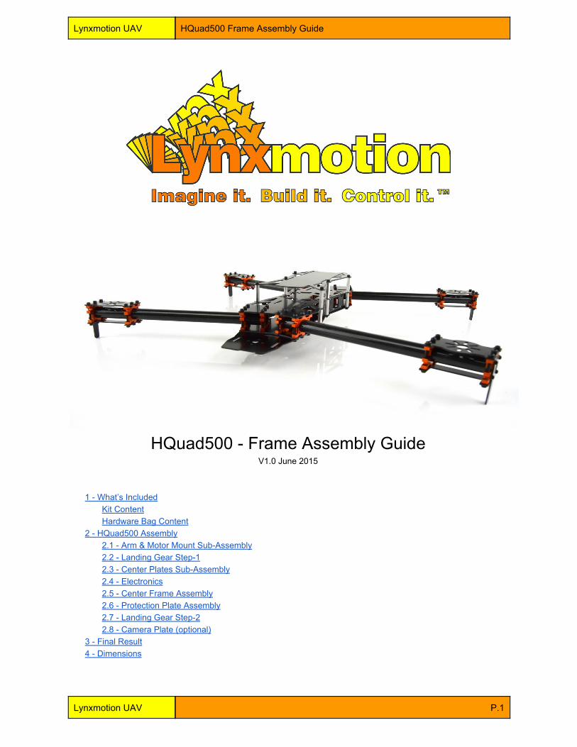
Lynxmotion UAV HQuad500 Frame Assembly Guide HQuad500 Frame Assembly Guide V1.0 June 2015 1 What’s Included Kit Content Hardware Bag Content 2 HQuad500 Assembly 2.1 Arm & Motor Mount SubAssembly 2.2 Landing Gear Step1 2.3 Center Plates SubAssembly 2.4 Electronics 2.5 Center Frame Assembly 2.6 Protection Plate Assembly 2.7 Landing Gear Step2 2.8 Camera Plate (optional) 3 Final Result 4 Dimensions Lynxmotion UAV P.1
Transcript of HQuad500 Frame Assembly Guide - Robot Store UAV HQuad500 Frame Assembly Guide 2.2 - Landing Gear...
Lynxmotion UAV HQuad500 Frame Assembly Guide
HQuad500 Frame Assembly Guide V1.0 June 2015
1 What’s Included Kit Content Hardware Bag Content
2 HQuad500 Assembly 2.1 Arm & Motor Mount SubAssembly 2.2 Landing Gear Step1 2.3 Center Plates SubAssembly 2.4 Electronics 2.5 Center Frame Assembly 2.6 Protection Plate Assembly 2.7 Landing Gear Step2 2.8 Camera Plate (optional)
3 Final Result 4 Dimensions
Lynxmotion UAV P.1

Lynxmotion UAV HQuad500 Frame Assembly Guide
1 - What’s Included We strongly suggest that you go over all the included parts to make sure you have everything before starting the assembly. This will also help you get used to the various components included in this kit.
Kit Contents ● 1x Lynxmotion UAV HQuad500 Hardware Bag ● 8x Lyxnmotion UAV 16mm Aluminum Clamp (2 pack)
○ 4x 16mm Aluminum Clamp Half ○ 8x 440 x ¼” Hex screw ○ 4x 440 x ¾” Hex screw ○ 4x 440 x ¼” Set screw ○ 8x 256 x ¼” Phillips screw
● 4x Lynxmotion Carbon Fiber Tube (16x14x220mm) ● 1x HQuad500 Top Plate ● 1x HQuad500 Bottom Plate ● 1x HQuad500 Protect Plate ● 4x HQuad500 Top Motor Mount ● 4x HQuad500 Bottom Motor Mount ● 1x HQuad500 Camera Plate ● 4x HQuad500 Side Plate (for ESC’s) ● 4x HQuad500 Tip Landing ● 4x HQuad500 Wire Cap ● 2x Lynxmotion Hook&Loop Strap
Hardware Bag Contents ● 12x 440 x 3/16” x 1” Aluminum Standoff ● 4x 440 x 3/16” x 0.25” Aluminum Standoff ● 12x 440 x ¼” Hex screw ● 8x 440 x ½” Set screw ● 8x 440 x 3/16” Hex screw ● 20x M3 x 5mm Hex screw ● 2x Adhesive Backed Foam strip ● 15x 3” Cable tie ● 4x Rubber Grommet ● 3/32” Hex Key
Note: hardware type / quantity may change slightly depending on availability.
Lynxmotion UAV P.2

Lynxmotion UAV HQuad500 Frame Assembly Guide
2 - HQuad500 Assembly We will explain the most optimal way to assemble the HQuad500 frame. Following this exact sequence is not mandatory but suggested. Go over all the steps at least once before starting the build.
2.1 - Arm & Motor Mount Sub-Assembly The following is the procedure for the assembly of one Motor Mount but, note that this same assembly should be done four times for the four different arms on the HQuad500. Considering that the clamps are asymmetric, you must take care to position them correctly. Material Needed (each arm):
● 4x 16mm Aluminum Clamp Half ● 1x HQuad500 Top Motor Mount ● 1x HQuad500 Bottom Motor Mount ● 8x 440 x ¼” Hex screw ● 4x 440 x ¾” Hex screw ● 4x M3 x 5mm Hex screw ● 1x Lynxmotion Carbon Fiber Tube (16x14x220mm) ● 1x Brushless Motor
1. Mount the clamps on the bottom motor mount using four 440 x ¼” Hex screws. You must use the two
threaded holes of the clamp to do so. Repeat the same step for the top motor mount as well.
Lynxmotion UAV HQuad500 Top & Bottom Clamps Assembly
Lynxmotion UAV P.3

Lynxmotion UAV HQuad500 Frame Assembly Guide
2. The installation of your Brushless Motor is easy at this stage. Place the motor on the top motor mount
assembly and align the wires so that they go on the side of the clamp leaving space for the tube. Insert the M3 x 5mm screws to secure the motor to the mount. (These screws are provided for most brand motors but we suggest to double check your motor specifications prior to using the provided M3 screws)
Lynxmotion UAV HQuad500 Brushless Motor Assembly
3. With the bottom mount assembly flat on the table, place the carbon fiber tube on the clamps and align the
end of the tube flush to the clamp.
Lynxmotion UAV HQuad500 Carbon Tube on Clamp
Lynxmotion UAV P.4

Lynxmotion UAV HQuad500 Frame Assembly Guide
4. Add the top motor mount assembly over the tube and insert two 440 x ¾” Hex screws to hold the two halves together. Then flip the assembly and insert the other two 440 x ¾” Hex screws and tighten them.
Lynxmotion UAV HQuad500 Top & Bottom mating
5. Make sure the spacing between the two clamp halves remains about the same and the tube sits flush to the
outside of the clamp.
Lynxmotion UAV HQuad500 Assembled Arm
Lynxmotion UAV P.5

Lynxmotion UAV HQuad500 Frame Assembly Guide
2.2 - Landing Gear Step-1 The landing gear is partially assembled here to have the motor wiring run inside the landing plate. It will not be bolted to the clamps yet to help with the arm assembly on a flat surface. Material Needed:
● 4x HQuad500 Tip Landing OR Wire Cap ● 4x Rubber Grommet
1. Insert the rubber grommet in the hole landing OR cap.
Lynxmotion UAV HQuad500 Wire Grommet
2. Run your motor wires inside the grommet and let the landing plate hang there until the step “2.7 Landing
Gear Step2”. We do not suggest to mount them on the frame at this step to be able to assemble the frame on a flat surface.
Lynxmotion UAV P.6

Lynxmotion UAV HQuad500 Frame Assembly Guide
2.3 - Center Plates Sub-Assembly The clamps are asymmetric and they need to be installed correctly on the top & bottom plates. Mostly to be sure the top & bottom will work together but also help with the Camera Plate mounting up front. To help with this process we named the sides of the clamps A and B.
Lynxmotion UAV HQuad500 Clamps Sides
Material Needed:
● 16x 16mm Aluminum Clamp Half ● 70x 440 x ¼” Hex screws ● 1x HQuad500 Top Plate ● 1x HQuad500 Bottom Plate ● 6x 440 x 3/16” x 1” Aluminum Standoff
1. Mount each Half Clamp on the frame keeping the right location of the A and B sides using two 440 x ¼”
Hex screws. Those two views are from the Inside of the frame and where the clamps should sit. This is also important as the mounting pattern for the Quadrino Nano features a cutout to allow advanced wiring and needs to match.
Lynxmotion UAV HQuad500 Center Plates Clamps Location
Lynxmotion UAV P.7

Lynxmotion UAV HQuad500 Frame Assembly Guide
2. Once assembled you will obtain an assembly that looks like this:
Lynxmotion UAV HQuad500 Center Plates Clamps
3. Add the 440 x 3/16” x 1” Aluminum Standoffs on the six locations in the image below, on the bottom plate
using 440 x ¼” Hex screws.
Lynxmotion UAV HQuad500 Center Plates Standoffs
Lynxmotion UAV P.8

Lynxmotion UAV HQuad500 Frame Assembly Guide
2.4 - Electronics At this stage it is the best time to mount the electronics before closing the two frame halves and add the arms. Since the ESC (electronic speed controller) will be mounted inside the frame we also recommend to test motor rotation for each arm location based on your flight controller recommendations. We provide ESC mounting plates that act as a frame stiffener as well. The ESC’s are held on the plate with 3” Cable ties.
Lynxmotion UAV HQuad500 Side Plate (for ESC’s)
Lynxmotion UAV P.9

Lynxmotion UAV HQuad500 Frame Assembly Guide
2.5 - Center Frame Assembly This step will assemble the previously made subassemblies and will truly put the frame together. We suggest to assemble it on a flat surface so all arms will stay level. Material Needed:
● 1x Top Plate SubAssembly ● 1x Bottom Plate SubAssembly ● 4x Arm SubAssembly ● 4x HQuad500 Side Plate (for ESC’s) ● 16x 440 x ¾” Hex screw
1. Place your bottom center plate subassembly on a flat table and place the arms over it’s half clamps.
Lynxmotion UAV HQuad500 Center Assembly Arms
Lynxmotion UAV P.10

Lynxmotion UAV HQuad500 Frame Assembly Guide
2. Now you can add the Side Plates to each of the four locations shown below. They insert easily in the slots of the bottom plate.
Lynxmotion UAV HQuad500 Center Assembly Side Plates
3. Install the top center plate subassembly on top of the bottom assembly and use 440 x ¾” Hex screws to
secure the two halves loosely from top and bottom. You will want to tighten the bottom ones slightly more and finish the tension with the top once it lays flat on the table. Remember to keep spacing roughly equal on both clamp sides.
Lynxmotion UAV HQuad500 Center Assembly Mating
Lynxmotion UAV P.11

Lynxmotion UAV HQuad500 Frame Assembly Guide
2.6 - Protection Plate Assembly
Material Needed: ● 1x HQuad500 Protect Plate ● 6x 440 x 3/16” x 1” Aluminum Standoff ● 6x 440 x ¼” Hex screw ● 6x 440 x ½” Set screw ● 2x Adhesive Backed Foam strip
1. Thread the six 440 x ½” set screws approximately half way of their length in the already mounted standoffs.
Lynxmotion UAV HQuad500 Protect Plate Set Screws
2. Add new 440 x 3/16” x 1” Aluminum Standoff on the set screws and tighten them.
Lynxmotion UAV HQuad500 Protect Plate Standoffs
Lynxmotion UAV P.12

Lynxmotion UAV HQuad500 Frame Assembly Guide
3. Take the protection plate and apply the two adhesive backed foam strips on them. This will help keep the battery in it’s location under heavy flight or crash.
Lynxmotion UAV HQuad500 Protect Plate Foam
4. Place the protection plate over the standoffs and secure it with 440 x ¼” Hex screws.
Lynxmotion UAV HQuad500 Protect Plate
Lynxmotion UAV P.13

Lynxmotion UAV HQuad500 Frame Assembly Guide
2.7 - Landing Gear Step-2 Material Needed: 16x 256 x ¼” Phillips screw
1. You can now finalize the installation of either the tip landing or wire cap to your arms using the 4 holes mounting pattern and 256 x ¼” Phillips screws.
Lynxmotion UAV HQuad500 Landing Gear Step2
Lynxmotion UAV HQuad500 Landing Gear
Lynxmotion UAV P.14

Lynxmotion UAV HQuad500 Frame Assembly Guide
2.8 - Camera Plate (optional) Material Needed:
● 1x HQuad500 Camera Plate
1. Flip your HQuad500 upside down and locate the four front facing 440 x ¼” Hex screws that hold the bottom half clamps. Remove them as the camera plate will use those for mounting.
Lynxmotion UAV HQuad500 Camera Plate Screws Removal
2. Install the camera plate over the holes and reinstall the 440 x ¼” Hex screws.
Lynxmotion UAV HQuad500 Camera Plate
Lynxmotion UAV P.15

Lynxmotion UAV HQuad500 Frame Assembly Guide
3 - Final Result The assembled frame should look like this after assembly. Plus all the electronics you added along the way.
Lynxmotion UAV HQuad500 Final Result
4 - Dimensions
Lynxmotion UAV HQuad500 Top Dimensions
Lynxmotion UAV P.16


![arXiv:1407.0927v1 [cs.SE] 3 Jul 2014Landing-Gear Extended Landing-Gear Retracted Landing-Gear Box Landing Wheel Door Figure 1: Landing Gear System such as airport runways [11]. Three](https://static.fdocuments.in/doc/165x107/5e9397289f16a23cdf089611/arxiv14070927v1-csse-3-jul-2014-landing-gear-extended-landing-gear-retracted.jpg)