HPE Helion OpenStack · HPE Helion OpenStack Page 3 . Executive summary OpenStack® is software...
22
HPE Helion OpenStack Deploy and maintain OpenStack for enterprises Technical white paper
Transcript of HPE Helion OpenStack · HPE Helion OpenStack Page 3 . Executive summary OpenStack® is software...

HPE Helion OpenStack Deploy and maintain OpenStack for enterprises
Technical white paper

HPE Helion OpenStack
Contents Executive summary ................................................................................................................................................................................................................................................................................................................................ 3 OpenStack deployment mechanisms .................................................................................................................................................................................................................................................................................... 4
RHEL OpenStack Platform (TripleO/Puppet) ......................................................................................................................................................................................................................................................... 4 SUSE OpenStack Cloud (Crowbar/Chef) ...................................................................................................................................................................................................................................................................... 6 Rackspace Private Cloud (Ansible) ................................................................................................................................................................................................................................................................................... 7 Mirantis OpenStack (Fuel) ........................................................................................................................................................................................................................................................................................................ 9
Deployment of HPE Helion OpenStack ........................................................................................................................................................................................................................................................................... 10 HPE Helion OpenStack 3.0 Deployment Architecture ................................................................................................................................................................................................................................ 10 Networking .......................................................................................................................................................................................................................................................................................................................................... 14 Initial deployment process .................................................................................................................................................................................................................................................................................................... 17 Maintain your OpenStack Deployment ..................................................................................................................................................................................................................................................................... 20
Additional Resources ........................................................................................................................................................................................................................................................................................................................ 22 References ........................................................................................................................................................................................................................................................................................................................................... 22 More information ........................................................................................................................................................................................................................................................................................................................... 22

HPE Helion OpenStack Page 3
Executive summary OpenStack® is software that controls large pools of compute, storage, and networking resources used to build open and extensible scale out clouds OpenStack consists of multiple inter-related components that can be controlled via a Web dashboard, command-line interface, or via RESTful APIs.
Designing, deploying, and configuring OpenStack based clouds is hard to do at enterprise scale—doing it in an automated fashion is even harder. Some of the challenges in designing an OpenStack deployment are:
• Figuring out the right OpenStack components for addressing various customer use cases
• Figuring out what open source or vendor specific tools and technologies can be deployed alongside OpenStack to fill gaps in OpenStack-like security, high availability, and manageability
• Orchestrating the deployment and configuration of these technologies on heterogeneous hardware systems
The OpenStack community and distro vendors have come up with a few different deployment methodologies for solving the above challenges. A basic pattern for creating OpenStack deployments at scale is:
• Modeling the cloud you want to build—this is about picking the right OpenStack components to run within your cloud, and mapping that to the physical infrastructure you want to run your cloud on
• Deploying your cloud—this is about using a set of open, extensible, and automated tools to prepare your physical infrastructure and install the OpenStack components you have chosen
• Configuring your cloud—this is about setting the right operational parameters for your cloud to be secure, resilient, and manageable
Other critical areas where vendors are trying to add value are:
• Patching and upgrades—ensuring that an OpenStack production deployment running workloads can be updated without impacting its end users can be tricky. Distro vendors usually provided tooling and documentation for upgrading their customer deployments with minimal downtime.
• Maintaining the infrastructure running the cloud—adding and removing hardware to/from a running OpenStack environment, and repairing OpenStack Control Nodes and shared services like MySQL and RabbitMQ could turn into a herculean task if done manually. Most vendors provide automated tools and playbooks for performing such common maintenance tasks.
This paper is targeted at IT architects who are designing OpenStack based clouds and lays out a few of the common approaches for designing and deploying OpenStack based clouds at scale. We look at some of the deployment mechanisms employed by different OpenStack vendors and contrast that with an open source Ansible based framework for configuration management of OpenStack clouds.
This paper is not meant to delve deep into scale and performance considerations when designing an OpenStack deployment—apart from pointing out design flexibility in these areas. Nor is this paper intended to provide guidance on the day-to-day operations, or the type of workloads, or even how to secure an OpenStack cloud. We’ll provide pointers to other resources that cover these areas in more detail.
This paper assumes that the target audience has a basic understanding of OpenStack architecture, its various components, and how they work together to create an Infrastructure as a Service (IaaS) platform.
HPE Helion OpenStack Page 4
OpenStack deployment mechanisms Planning for a deployment of OpenStack requires identifying the servers to run your OpenStack cloud, the networks to interconnect them, the storage you will need, the service level agreement (SLA) you want to support, just to name a few. This in turn depends upon the use cases you need to support, the workloads you want to run, the internal or external customers you want to serve, and other variables.
Similarly, the internal expertise you have will influence your choice for which deployment mechanism might be best suited for you. For example, you should use a hypervisor that is well known to your organization or meets your compliance/security needs. If your organization is familiar with and already has the skills for configuration management tools such as Chef or Ansible, you might want to use deployment tooling that uses the same technologies.
There are multiple options when it comes to designing and deploying an OpenStack based cloud, and there is no right or wrong choice. Deployment mechanisms are also one of the differentiators amongst OpenStack vendors and each comes with its own set of pros and cons. But, one thing is generally agreed upon by the OpenStack community—it is not good practice to try and setup OpenStack manually for anything except experimentation. The various installers, deployers, and configuration management systems offer definite value by simplifying the task of installing OpenStack and making it usable.
The next few sub-sections introduce some of the major deployment mechanisms available for OpenStack as of the Mitaka release:
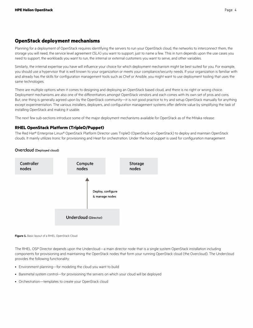
RHEL OpenStack Platform (TripleO/Puppet) The Red Hat® Enterprise Linux® OpenStack Platform Director uses TripleO (OpenStack-on-OpenStack) to deploy and maintain OpenStack clouds. It mainly utilizes Ironic for provisioning and Heat for orchestration. Under the hood puppet is used for configuration management.
Figure 1. Basic layout of a RHEL OpenStack Cloud
The RHEL OSP Director depends upon the Undercloud—a main director node that is a single system OpenStack installation including components for provisioning and maintaining the OpenStack nodes that form your running OpenStack cloud (the Overcloud). The Undercloud provides the following functionality:
• Environment planning—for modeling the cloud you want to build
• Baremetal system control—for provisioning the servers on which your cloud will be deployed
• Orchestration—templates to create your OpenStack cloud
HPE Helion OpenStack Page 5
The Overcloud is the resulting Red Hat Enterprise Linux OpenStack Platform environment created using the Undercloud. This includes one or more:
• Controllers—nodes providing administration, networking, and high availability for the OpenStack environment
• Compute—nodes used to provide computing resources to the OpenStack environment
• Storage—nodes that provide storage for the OpenStack environment. These are nodes for Ceph Object Storage, Cinder Block Storage, or Swift Object Storage
A typical RHEL OSP installation includes the following steps:
• Setting up an environment to provision Red Hat Enterprise Linux OpenStack Platform using the director. This includes setting up the servers that would run the RHEL OSP Director and the Undercloud, and one networks for provisioning and managing the Overcloud nodes, and another network for remote connectivity to all nodes. You will also need to setup and synchronize the RHEL repositories necessary for RHEL OSP.
• The first step to creating your Red Hat Enterprise Linux OpenStack Platform environment is to install the director on the Undercloud system, and this involves
– Creating a Director installation user
– Creating directories for templates and images
– Setting the hostname for the system
– Registering your system
– Installing the Director packages
– Configuring the Director
– Obtaining images for Overcloud nodes
– Setting a name server on the Undercloud’s Neutron subnet
– Completing the Undercloud configuration
• Planning your Overcloud and defining node roles, network topology, and storage is the part where you model what your running OpenStack cloud will look like. RHEL OSP allows you to specify different roles like Controller, Compute, and Storage to the nodes on the Overcloud. You can also specify multiple networks that map different services to separate network traffic types assigned to the various subnets in your environments.
• Selecting or defining Heat templates for deploying the various OpenStack services that make up the Overcloud is needed before kicking off the installation of the Overcloud. RHEL OSP ships with default director templates and plans that can be used to create the Overcloud.
• Creating the Overcloud is a fairly involved process, but the RHEL OSP installation guide documents a couple of scenarios with medium to high complexity. The advanced scenario includes instructions for enabling Ceph storage, network isolation, and high availability configurations.

HPE Helion OpenStack Page 6
SUSE OpenStack Cloud (Crowbar/Chef) SUSE OpenStack Cloud is based on SUSE Linux Enterprise Server, OpenStack, Crowbar, and Chef. SUSE Linux Enterprise Server is used as the underlying operating system for all cloud infrastructure machines (also called nodes). The cloud management layer, OpenStack, works as the Cloud Operating System. Crowbar and Chef are used to automatically deploy and manage the OpenStack nodes from a central Administration Server.
Figure 2. Basic layout of a SUSE OpenStack Cloud
A typical SUSE OpenStack Cloud is deployed to four different types of machines:
• One Administration Server for node deployment and management—The Administration Server provides all services needed to manage and deploy all other nodes in the cloud. Most of these services are provided by the Crowbar tool that—together with Chef—automates all the required installation and configuration tasks. Among the services provided by the server are DHCP, DNS, NTP, PXE, and TFTP.
• One or more Control Nodes hosting the cloud management services—The Control Node(s) hosts all OpenStack services needed to orchestrate virtual machines deployed on the Compute Nodes in the SUSE OpenStack Cloud. Being a central point in the SUSE OpenStack Cloud architecture that runs a lot of services, a single Control Node can quickly become a performance bottleneck, especially in large SUSE OpenStack Cloud deployments. It is possible to distribute the services listed above on more than one Control Node, up to a setup where each service runs on its own node.
• Several Compute Nodes on which the instances are started—The Compute Nodes are the pool of machines on which the instances are running. These machines need to be equipped with a sufficient number of CPUs and enough RAM to start several instances. The Control Node effectively distributes instances within the pool of Compute Nodes and provides the necessary network resources. The OpenStack service Compute (Nova) runs on the Compute Nodes and provides means for setting up, starting, and stopping virtual machines.
• Several Storage Nodes for block and object storage—The Storage Nodes are the pool of machines providing object or block storage. Object storage is provided by the OpenStack Swift component, while block storage is provided by Cinder which supports several different back-ends, among them Ceph, which can be deployed during the installation.

HPE Helion OpenStack Page 7
A typical installation workflow for SUSE OpenStack cloud looks as follows:
• Setup the Administration Server—this runs SUSE Linux Enterprise Server as the Operating System and includes the SUSE OpenStack Cloud extension and, optionally, the Subscription Management Tool (SMT) server. Crowbar and Chef are also setup on this server.
• Setting up the OpenStack nodes and services is done using the Crowbar Web Interface. The Crowbar Web interface runs on the Administration Server. It provides an overview of the most important deployment details in your cloud, including a view on the nodes and which roles are deployed on which nodes, and on the barclamp proposals that can be edited and deployed. In addition, the Crowbar Web interface shows details about the networks and switches in your cloud. It also provides graphical access to some tools with which you can manage your repositories, back up or restore the Administration Server, export the Chef configuration, or generate a supportconfig TAR archive with the most important log files.
Rackspace Private Cloud (Ansible) Rackspace Private Cloud uses a mixture of Ansible and Linux Containers (LXC) to install and manage OpenStack. Ansible provides an automation platform to simplify system and application deployment. Ansible manages systems using Secure Shell (SSH) instead of unique protocols that require remote daemons or agents. Linux Containers provide operating-system level virtualization by enhancing the concept of chroot environments, which isolate resources and file systems for a particular group of processes without the overhead and complexity of virtual machines. They access the same kernel, devices, and file systems on the underlying host and provide a thin operational layer built around a set of rules.
Figure 3. Basic layout of a Rackspace Private Cloud
The recommended layout for a Rackspace Private Cloud contains a minimum of five hosts:
• Three Control Plane infrastructure hosts—containing shared infrastructure services like Galera and RabbitMQ, and OpenStack services like Keystone and Glance
• One logging infrastructure host—containing logging technologies like the ELK (Elasticsearch, Logstash, and Kibana) stack
• One compute host—containing the services necessary for running compute (like Nova) and logging agents
• An optional block storage host can also be added—containing the block storage scheduler and volumes for block storage

HPE Helion OpenStack Page 8
The installation workflow for a Rackspace Private Cloud running OpenStack is as follows:
• Prepare deployment host—The deployment host contains Ansible and orchestrates the RPCO installation on the target hosts. One of the target hosts, preferably one of the infrastructure variants, can be used as the deployment host. The deployment host needs an Operating System installed and configured, RPCO source and dependencies installed, and SSH keys configured for connectivity between the deployment and target hosts.
• Prepare target hosts—The RPCO installation process requires at least five target hosts that will contain the OpenStack environment and supporting infrastructure. On each target host, perform the following tasks:
– Naming target hosts
– Install the operating system
– Generate and set up security measures
– Update the operating system and install additional software packages
– Create LVM volume groups
– Configure networking devices
• Configure deployment—Ansible references a handful of files containing mandatory and optional configuration directives. These files must be modified to define the target environment before running the Ansible playbooks. Perform the following tasks:
– Configure Target host networking to define bridge interfaces and networks
– Configure a list of target hosts on which to install the software
– Configure virtual and physical network relationships for OpenStack Networking (Neutron)
– Configure service credentials
– (Optional) Set proxy environment variables
– (Optional) Configure the hypervisor
– (Optional) Configure Block Storage (Cinder) to use the NetApp back end
– (Optional) Configure Block Storage (Cinder) backups.
– (Optional) Configure Block Storage Availability Zones
– Configure passwords for all services
– Configure Dashboard SSL settings (optional)
• Run foundation playbooks—The main Ansible foundation playbook prepares the target hosts for infrastructure and OpenStack services and performs the following operations:
– Perform deployment host initial setup
– Build containers on target hosts
– Restart containers on target hosts
– Install common components into containers on target hosts
• Run infrastructure playbooks—The main Ansible infrastructure playbook installs infrastructure services and performs the following operations:
– Install Memcached
– Install Galera
– Install RabbitMQ
– Install Rsyslog
– Install Elasticsearch

HPE Helion OpenStack Page 9
– Install Logstash
– Install Kibana
– Install Elasticsearch command-line utilities
– Configure Rsyslog
• Run OpenStack playbooks—The main Ansible OpenStack playbook installs OpenStack services and performs the following operations:
– Install common components
– Create utility container that provides utilities to interact with services in other containers
– Install Identity (keystone)
– Generate service IDs for all services
– Install the Image service (Glance)
– Install Orchestration (Heat)
– Install Compute (Nova)
– Install Networking (Neutron)
– Install Block Storage (Cinder)
– Install Dashboard (Horizon)
– Reconfigure Rsyslog
Mirantis OpenStack (Fuel) Fuel is a deployment tool that simplifies installation of Mirantis OpenStack (MOS). Using Fuel, you can deploy multiple highly-available OpenStack environments. Fuel includes scripts that dramatically facilitate and speed up the process of cloud deployment, without requiring you to completely familiarize yourself with the intricate processes required to install the OpenStack environment components.
Fuel consists of several independent, open source components like Cobbler for provisioning, and Puppet for configuration management—wrapped together to provide an intuitive, GUI-driven experience for deployment and management of Mirantis OpenStack.
Figure 4. Basic architecture of Mirantis Fuel

HPE Helion OpenStack Page 10
Fuel includes the following components:
• Fuel Master node—A standalone physical or virtual machine server from which you provision your OpenStack environments.
• Fuel Slave nodes—Servers or node servers, that can be controller, compute, storage, or other nodes.
The typical installation workflow for Mirantis OpenStack using Fuel as the deployment technology is a bit different than the methods mentioned above. This is because the Fuel UI abstracts away all of the underlying functionality and makes it easy to do basic installations of OpenStack via the GUI. The steps for getting started with Mirantis OpenStack using Fuel are roughly as follows:
• Install VirtualBox—the Fuel Master node can be run from a virtual machine
• Download Mirantis OpenStack and associated scripts—this contains Fuel, and the tooling necessary to setup Mirantis OpenStack
• Edit basic configuration needed to bring up the Fuel Master node
• Run a script that sets up Fuel components
• Login to the Fuel GUI to assign roles to the slave nodes, change OpenStack services configuration, and deploy multiple MOS clouds
Fuel is also accessible via a REST API, and via a CLI. Some of the advanced deployment options for Mirantis OpenStack can be enabled by editing YAML configuration files and running the Fuel CLI. Fuel also has a Plugin mechanism allowing third-party vendors to package OpenStack drivers and dependent code/configuration into Fuel Plugins that can be used from a Fuel Plugin Catalog—Cisco ACI for networking and EMC ScaleIO for storage are examples.
Deployment of HPE Helion OpenStack HPE Helion OpenStack is OpenStack technology coupled with Linux for HPE Helion and a number of HPE value-added services that complement and enhance OpenStack. HPE Helion OpenStack can be used to set up private cloud environments that scale from a few nodes up to 200 Compute Nodes.
A new OpenStack environment is built by assembling and configuring sets of OpenStack services on to one or more servers that have been assigned to the cloud. Each service provides a distinct capability (such as Nova for compute or Neutron for Network services) and it is through the interaction of these core sets of services that cloud functionality is delivered to the consumer.
HPE Helion OpenStack 3.0 Deployment Architecture OpenStack uses an architecture where communications between services is performed over the network. This approach enables OpenStack services to be distributed in a wide variety of ways over available servers so that OpenStack clouds with differing characteristics can be built. The Swift Object storage service is an example of a scale-out service architecture.
The task of installing and configuring a new OpenStack cloud involves an initial design phase where the layout of the required OpenStack services are mapped onto a set of servers based on specific requirements for the cloud. Once the design has been decided, the appropriate servers are then installed with an Operating System and the OpenStack software. With the software installation phase completed, a configuration phase is initiated where the Operating System and OpenStack software stack is setup as per the design.
Performing this software installation and configuration activity is a time consuming, complex and often error prone process. To help with this process, HPE Helion OpenStack 3.0 provides lifecycle management features as a way to simplify and accelerate the process of installing and performing ongoing lifecycle operations for OpenStack clouds.
Lifecycle management HPE Helion OpenStack 3.0 includes lifecycle management that allows for the intelligent mapping of OpenStack services to the available server resources that have been assigned for use by the cloud. The lifecycle management uses the Ansible open source automation tool for deploying and configuring the OpenStack Software.
Lifecycle management goes beyond the initial installation process to provide lifecycle operations for the cloud once it has been deployed. For example, it provides capabilities that enable:
• The addition of servers to select existing services so that their capacity can be expanded. For example, adding in more Swift Object storage nodes once capacity or performance of the current configuration is insufficient.

HPE Helion OpenStack Page 11
• The creation of select new services after the cloud is already operational. For example, the addition of a HPE 3PAR storage array as a new Cinder block storage source.
• The reconfiguration of existing OpenStack services.
• The patching and upgrading of the Operating System and Helion OpenStack software.
HPE Helion OpenStack 3.0 clouds are defined through a set of configuration files that can either be edited directly in a text editor. Rather than needing to define each cloud from scratch every time, Helion OpenStack 3.0 includes a series of starting point examples that reflect some of the more common cloud configurations in use today. When deploying an initial Helion OpenStack 3.0 cloud, the customer can choose one of the supplied examples that is closest to their desired end state configuration and modify it with the specific configuration data for their environment.
The lifecycle management enables the mapping between named sets of OpenStack services to one or more groups of servers so that the right level of resources can be applied to the needs of the specific services in the cloud. For example, the resource needs for object storage can become substantial as the cloud workload grows. With Helion OpenStack 3.0, a configuration can be defined where a separate group of servers is allocated and dedicated to Swift Proxy or object workloads, removing those loads from the core OpenStack controller nodes.
Control Plane The lifecycle management introduces the concept of a Control Plane with clusters and resources, as ways to group together related OpenStack services and their servers. Services located on clusters in the Control Plane generally provide cloud control and management capabilities while services on resources run workloads for end users such as compute or storage.
The configuration data provided to lifecycle management includes a specification of how many servers should be placed in Control Plane clusters and resources and exactly which services are mapped to those servers. Helion OpenStack 3.0 enables collections of services to be assigned to one or more servers within the configuration. Using more than one server for a set of services helps to address both the scalability and availability needs of those services.
Figure 5 illustrates an example where the use of clusters in the cloud’s Control Plane bring greater scale and availability to the Helion OpenStack cloud solution. This particular larger scale configuration example has two 3 node clusters and 9 resource servers in the Control Plane. The number and types of clusters deployed and the number of resource servers used can be varied so that specific target cloud capacity and availability needs are met.
Figure 5. HPE Helion OpenStack Server Groups and Roles

HPE Helion OpenStack Page 12
In this example, the Clusters group shows how two groups of servers can be defined with each group having their own distinct role:
• The first grouping labeled CONTROLLER-ROLE in the Clusters group has three servers assigned to it and contains the core OpenStack services and supporting database, messaging and clustering technologies. This set of servers forms the “heart” of the HPE Helion OpenStack 3.0 cloud and due to the importance of these services to maintaining cloud availability they are automatically configured into a high availability cluster. Clustering these core services means that should any one of the servers within the cluster fail, the HPE Helion OpenStack 3.0 cloud continues to operate.
• The second grouping labeled SWPAC-ROLE in the Clusters group is the Swift Proxy component that accepts requests for Swift Object data which then works with the relevant Swift Object servers to retrieve the data. The Swift Proxy server role also includes services used to store and manage the Swift Account and Container data. To improve the durability and availability of the Account and Container data, Swift uses replication so that the data is spread over multiple servers. In this example, three servers are used in the Swift Proxy role enabling three copies of the data to be replicated over the nodes.
The resource group includes three groups of servers that are dedicated to providing compute and storage resources to the user’s cloud instances.
• The first group of servers in the diagram provides the compute capability where instance Virtual Machines are instantiated and run. On receiving a request for a new instance, HPE Helion OpenStack 3.0 selects one of the compute servers from this group and begins the process of defining the VM and allocating resources to it.
In this specific case, a single group of compute server is shown in the diagram but more complex models can also be created. For example, the group of compute servers can be defined and distributed across Availability Zones. Availability Zones are an OpenStack construct that helps to enhance application availability by ensuring that a failure in one Availability Zone does not impact workload running in a different Availability Zone.
A total of three compute servers are currently shown in the diagram but this number can be expanded after an initial installation has completed to allow growth of the compute resources over time.
• The second group of servers is dedicated to providing Cinder block storage resources for use by instances. In this particular design, we use HPE’s StoreVirtual VSA software to enable reliable storage to be defined and attached to running instances via the iSCSI protocol. The example shows three servers with VSA software installed (the minimum number required for Highly Available Cinder block storage with VSA) but the number of VSA servers can be expanded after the initial installation should block storage requirements increase.
• The final group of servers is the Swift Object storage servers. This group of servers is used by the Swift software to store the user’s object data. Three distinct servers are typically used so that three copies of the data can be made with each copy of data residing on a different server. As with the other resource nodes, additional Swift Object storage servers can be added after the initial installation has been completed allow for the capacity of the Swift Object storage to be grown.
Server Roles The Helion OpenStack 3.0 model uses the concept of a Server Role when defining the characteristics of the required servers to be assigned for use with groups. A Server Role definition in Helion OpenStack 3.0 includes references information about the networking and storage configuration that is expected of the server. The installer uses this information in conjunction with higher-level Networking and Storage definitions to correctly configure servers so that features such as NIC bonding, network separation through multiple VLANs and multiple disk support can be enabled.
As part of the cloud configuration process, every server used within the cloud is defined in the data model. In that definition process, a specific Server Role is assigned to each server based on that server’s hardware configuration meeting the requirements as defined in the Server Role. As the cloud is deployed, servers are selected for use with specific service groups based on matching the Server Role specifications from the group with the available set of servers that have been tagged with that same Server Role.
An important step in any cloud deployment is the initial design phase where the architecture of the cloud is determined. Understanding how services will be grouped together and what the Server Roles characteristics are for those groups is a key decision that impact the overall capabilities of the cloud. Understanding the required characteristics of each Server Role will assist in the detailed configuration process for the individual servers that will be needed for the cloud to operate properly.

HPE Helion OpenStack Page 13
Failure Zones Enabling high availability for applications is a key capability within the private and public cloud settings. A common strategy used by cloud-native applications to improve availability is to break down the application into smaller stateless components that are distributed and replicated over the available compute environments. The application is specifically designed such that if one of the replicated components fails then other application components that are already active and processing the workload can take over the requests from the failed component and the application remains available.
Application components gain access to data through managed resources in the cloud such as database servers and message queues. Highly available applications need their data resource providers to also maintain high levels of service availability and data durability and a common approach to achieving this is through the use of data replication across multiple instances of a given resource provider.
Supporting this model for achieving high availability for cloud native applications requires that application and data components be distributed over compute servers that are not susceptible to any single point of failure. For example, if all of the cloud native application components are distributed over servers that share a common power source then any failure of that power source will bring down all of the application and availability will be lost.
These groups of compute and storage resources are called Failure Zones within the Helion OpenStack model, and are achieved by designing the hardware in each Failure Zone to not share any common single points of failures. For example, distinct Failure Zones will often use separate power sources for the servers and storage arrays, have different paths into the network from each Failure Zone and perhaps even be located in different machine rooms with independent cooling systems.
To communicate the relationship of servers to one another from a networking and failure isolation point of view Helion OpenStack 3.0 uses hierarchical server groups. Failure Zones are then formed by indicating which server groups have the same shared dependencies (such as power, networking, etc.) and hence can be formed into a single Failure Zone.
Although Failure Zones have been described here in terms of in-cloud workloads the same practice can also be applied to the OpenStack services themselves. Helion OpenStack 3.0 automatically deploys the cloud’s OpenStack service controllers in a three nodes cluster and if Failure Zones have been defined then those cluster nodes can be distributed amongst them. This helps to further enhance the availability of the cloud by ensuring that cluster services are appropriately distributed over sets of fault isolated servers.
Figure 6 illustrates how the logical cloud design first introduced in figure 5 can be deployed using a three rack system with three Failure Zones.
Figure 6. HPE Helion OpenStack Failure Zone example

HPE Helion OpenStack Page 14
OpenStack includes the concept of Availability Zones that is used by OpenStack to enable multiple instances of cloud resources (such as compute, Swift and Cinder block storage) to operate on their own set of fault isolated hardware. For example, in Helion OpenStack 3.0 we support Nova Availability Zones where each Nova Availability Zone maps to a group of compute servers that are in located in the same Failure Zone. When creating instances in the cloud, the user can specify which Nova Availability Zone to use and Helion OpenStack will ensure that the instance is then placed only a server in that Availability Zone.
OpenStack includes the concept of Availability Zones for Swift and Cinder data sources too—Helion OpenStack 3.0 supports Swift Availability Zones, but does not support Cinder Availability Zone configurations.
Networking Networking in HPE Helion OpenStack allows great flexibility both in terms of the networks used for the cloud infrastructure as well as the range of networking options that cloud end user instances can utilize for connectivity between instances and external networks.
From a cloud infrastructure perspective, HPE Helion OpenStack 3.0 enables the cloud administrator to define a distinct series of networks with each network dedicated to a specific category of traffic. The cloud administrator can split each of these traffic types onto their own independent network. Having different networks that are dedicated to specific purposes enables greater network separation and a more secure environment since multiple categories of network traffic do not share a single network.
Figure 7. HPE Helion OpenStack Failure Zone Example
Figure 7 shows a possible example HPE Helion 3.0 configuration where separate VLANs and an untagged network are used for the different traffic patterns involved in this particular cloud.

HPE Helion OpenStack Page 15
A brief description of these different network types and how they are used within the Helion OpenStack configuration is provided below.
Table 1. HPE Helion OpenStack Network Types Example.
Network Description
Management This network is used by Helion OpenStack for management traffic that flows between all of the servers that participate in the cloud.
The traffic includes exchanges between the OpenStack components that make up the cloud as well as monitoring data that is used to constantly evaluate the cloud’s current health. Collection of monitoring information allows for historical cloud usage data to be stored as well as enabling the evaluation of specific metrics with the goal of producing alerts should an unexpected out of band condition occur.
In this specific example, the management network is also used during the initial installation of the Helion OpenStack 3.0 cloud. Helion OpenStack is delivered with a default cloud server installation mechanism using the Open Source Cobbler software. Cobbler uses network boots via PXE to initiate the Linux for HPE Helion operating system installation on the cloud nodes which in this cases uses the combined PXE and Management network. The PXE network is also used during the early phases of the cloud deployment process for operating system specific configuration activities.
As an alternative, Helion OpenStack 3.0 also allows for the definition of a separate PXE network that is distinct from the Management network. Because this network requires that the cloud servers’ network boot from it via PXE then it must be presented to the server as an untagged network.
External-VM The OpenStack external network is designed to allow cloud user instances to gain connectivity to a network that is “external” from the core cloud. For example, in a public cloud, the external network could be connected to the Internet allowing cloud instances to be accessible to users on the Internet. In the case of a private cloud, the external network might be connected to the company’s intranet allow company employees to access applications hosted within the cloud.
The External VM network is most often configured using a tagged VLAN although it is possible to have a dedicated untagged VLAN if sufficient network trunks are available.
Helion OpenStack 3.0 supports the use of multiple external networks. This can be useful if your cloud is implemented in a multi-tenant environment where you want to assign external networks to specific users or groups of users for security reasons.
Swift (Object storage) The Swift Object storage software offers a variety of ways to deploy its constituent Proxy, Account, Container, and Object roles across multiple servers. One common deployment pattern is to use a two-tier strategy where the first tier hosts the Proxy, Account and Container roles while the second tier is responsible for the Object storage role. Each tier is made up of multiple servers.
Networking traffic between the Proxy servers and the Object servers can be substantial as data validation and replication operations occur in parallel to the Swift cluster handling end user requests for object data.
Creating a separate Swift network also removes the Swift-specific traffic from the management network meaning that a greater network separation is achieved leading to improved security.
The Swift network is most often assigned to a tagged VLAN.
iSCSI (Block storage) The block storage network is designed to exclusively handle iSCSI based networking traffic.
In our sample configuration we use VSA servers to provide Cinder block storage support which uses iSCSI as its data transport mechanism. The block storage network connects together the VSA servers that are providing iSCSI data access with the compute servers and core Control Plane servers that are both Cinder block storage consumers.
Having a separate block storage network enables greater network separation leading to improved security since iSCSI traffic is restricted to only this network. It can also help to improve performance since the iSCSI traffic does not have to share the network with other data or control communications.
The block storage network is most often assigned to a tagged VLAN.
Guest A common approach to implementing guest networking in OpenStack is to use an encapsulation protocol such as VxLAN to act as the transport mechanism for each of the tenant networks. Using VxLAN allows for substantially greater numbers of guest networks as compared to technologies such as VLANs thereby enhancing the cloud’s scalability.
The guest network is a network dedicated to transporting the VxLAN protocol between Compute Nodes and to Neutron services found in the core Control Plane. Within the Helion OpenStack 3.0 cloud, VxLAN tenant networking traffic is restricted to the underlay network only meaning that guest networking traffic is not found on other networks in the cloud. Restricting the guest networking traffic to a single network leads to greater security and potentially improved performance.
The guest network is most often implemented as a tagged VLAN.
Provider Network(s) Provider networks in OpenStack allow for a cloud administrator to connect specific VLANs to a tenant allowing instances under that tenant access to data center resources that are connected to the VLAN.
For example, if a data center has a dedicated set of database servers outside of the cloud that expose their services through the network tagged with VLAN 500 then a cloud administrator can attach VLAN 500 to a specific tenant allowing that tenant’s instances gain access to those database services.
Helion OpenStack 3.0 allows the use of provider networks to define which network interface is used for accessing the range of desired VLANs.

HPE Helion OpenStack Page 16
Although the example illustrates how Helion OpenStack 3.0 can define networks so that there is clear network separation between the different traffic types for better security and performance, it is also possible to create configurations where one or more of these networks can be combined with the management network to reduce the overall required network link count. A cloud architect can decide which networks require to have their own dedicated links and then configure the remaining networks to automatically be assigned to the “default” network. The “default” network is usually the Management Network.
As an example, a cloud could be defined where Swift and block storage networking traffic is assigned to the management network but the tenant and external networks each have their own dedicated VLAN.
Helion OpenStack 3.0 also includes support that enables the use of multiple NIC cards within each server and to optionally assign NIC cards into network trunks for even greater availability and throughput. Each of the networks defined for a particular HPE Helion cloud configuration can be assigned to a specific NIC or a group of NICs combined together in a trunked configuration. This allows for even greater network separation since not only can traffic types be assigned to individual VLANs but those VLANs can be assigned to a specific NIC or trunk on the server.
The example in figure 7 illustrates six different networks defined for use by the cloud. Each server is configured to connect the networks it requires for its role. For example, the Swift Object servers have the Management and Swift networks assigned to them but they do not require the iSCSI block storage, tenant or any of the other defined network types to operate.
As an example, in figure 7 the Swift Object servers might have just a single network trunk consisting of two 10 Gb/s NICs with management and swift storage traffic. The core controllers and compute servers on the other hand may have two network trunks allowing for the separation and balancing of traffic with one trunk dedicated to accessing data (iSCSI block storage) while the other is used for general management and instance networking traffic (Management, External-VM, External-API, Provider VLANs and guest).
How the different networks are mapped to one or more NICs and/or trunks is configurable by the cloud administrator during the installation process so that any special cloud design considerations around network separation or anticipated network bandwidth requirements can be met.
Load balancers and Control Plane high availability Helion OpenStack automatically configures the core set of OpenStack and HPE Helion services within a highly available configuration consisting of a cluster of three servers. These are the three servers shown in the core Control Plane cluster in earlier diagrams.
Cluster aware core services are run on each of the three core controller servers and a load balancer is used to direct incoming requests to a functioning service instance within the cluster. Rather than exposing the three different service endpoints associated with the services on each of the three cluster members, the load balancer presents a single virtual IP (VIP) instead. Service users’ contact this well-known virtual IP address when requesting access and do not need to know the details of where the actual processing occurs. Note that internal and external access to services are completely separate, so that the external access can be configured to use fully qualified domain names (FQDNs) and security certificates that the customer supplies.
Helion OpenStack 3.0 provides an internal load balancer and this is implemented using HAProxy software running on the core controllers. The cloud administrator indicates what load balancer configuration is required through specifications given to Helion OpenStack 3.0.
Security considerations during deployment HPE Helion OpenStack 3.0 addresses a few key security concerns during the deployment process. A couple of automated tools that the HPE security team uses before certifying a HPE Helion OpenStack release are Bandit and Recon. Bandit is a Python source code analyzer, and Recon performs analysis of a running operating system to determine what hardening opportunities exist.
One of the major security features of HPE Helion OpenStack 3.0 is a reduced attack surface. HPE Helion OpenStack 3.0 use HPE Linux for Helion as the Host OS for the Control Plane, which is a hardened version of Debian pulling in only those packages from top of the Debian tree required to run HPE Helion OpenStack.
HPE Helion OpenStack 3.0 also uses a variety of security best practices during deployment and maintenance activities to prevent escalation of privilege attacks—including setting up a secure/standalone deployer node running on isolated networks, SSH and encryption keys protected by passphrases, sudo restrictions via sudoers file, encryption of inter-service passwords, ability to change the passwords, not storing clear text passwords in configuration files, and protecting configuration files using filesystem controls. On top of this, audit logs of all activities performed during deployment and maintenance are available in common standards like CADF.

HPE Helion OpenStack Page 17
Initial deployment process The HPE Helion OpenStack 3.0 installation process is based on multiple phases. The initial phase is to setup the physical infrastructure so that the cloud can be connected to the real world. Next, the cloud architect defines the model of the multi-tenant virtual infrastructure, and how it maps onto the physical data center. The model is checked in to a local GIT repository to maintain revision control and change management. The configuration processor translates the cloud model into configuration files and creates a staging area for deployment. Finally, there are two phases of the installation. The first is to install a basic Linux for HPE Helion operating system onto each node in the cloud (with SSH and shared keys enabled). Helion OpenStack 3.0 Ansible playbooks install and configure the cloud based on the configuration files generated by the configuration processor.
Figure 8. HPE Helion OpenStack initial deployment process
Setup physical infrastructure There are multiple elements to the physical infrastructure that need to be configured: server, storage, network, management, security and shared services.
For each server, there are settings in the BIOS/firmware, Intelligent Platform Management Interface (IPMI), network interface cards (NICs), and storage subsystem that need to be configured. These can be done manually or with automation tools. Examples are enabling CPU virtualization for Compute Nodes, configuring IPMI for baremetal provisioning, and configuring local storage devices.
Helion OpenStack 3.0 utilizes three types of storage: ephemeral, block and object. These can be implemented with local disks, software-defined storage, and storage area networks (SANs). Whether local or remote, the appropriate storage needs to be created and presented to the appropriate server. Examples include configuring local storage arrays to present RAID volumes, utilizing iSCSI or FC SANs to present remote devices as local, and configuring security and zoning for SANs.
Preparing the physical network infrastructure to connect to the physical and virtual cloud networking is often the most time consuming preparation step. Example tasks include configuring network aggregation for HA and bandwidth, VLAN and CIDR definitions, network separation for bandwidth and security, and connectivity for shared services via Layer-2 and Layer-3.
Management tools are included with Helion OpenStack 3.0 to install the cloud. These include using IPMI and Cobbler to setup the physical environment. An IPMI administrator level user needs to be available to check and control the state of the physical servers. Depending on the server platform selected, the IPMI administrator could be a local user or a user based on authenticating via directory services.
HPE Helion OpenStack Page 18
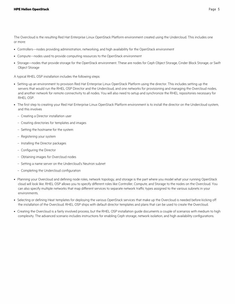
Define Cloud Model Once the physical infrastructure is prepared, the data model needs to be defined for the cloud. This includes defining the Control Plane, networks, network groups, firewall, servers, server roles and server groups.
HPE provides multiple example starting points that customers will modify to meet their business needs. The customer can specify the data model through the Day Zero GUI experience, or by manually editing the example model YML files. Please note that the Day Zero GUI provides basic configuration abilities, while manual editing allows complete flexibility.
Figure 9. HPE Helion OpenStack Cloud Input Model
The Helion OpenStack 3.0 Control Plane model supports a single Control Plane. This specifies Failure Zones, common service components, clusters, and the services that run in the Control Planes. Example services include OpenStack services such as Keystone, Glance, Nova, and Neutron as well as infrastructure services such as NTP, MySQL, RabbitMQ, and Logging. Defining multiple clusters allows you to split up services that need additional scalability and performance.
Also defined in the Control Plane model are resources, which includes compute and storage services. Examples for compute services include Nova KVM compute and Neutron agents. Examples for storage services include Virtual SAN Appliance services. Please note that certain storage services like Swift can be defined in the Control Plane to reduce overall server count.
The networks model specifies which physical networks are defined in the cloud, and what network groups that they are associated with. Examples of networks are External API, External VM, Guest (internal), and Management networks. Additional networks can be defined for network separation, for example a dedicated iSCSI network. These networks can be specified with tagged and untagged VLANs, and with gateways if they are meant to be routable.
A network-group defines the traffic separation model, and all of the properties that are common to the set of L3 networks that carry each type of traffic. They define where services are attached to the network model, and the routing within that model. The details of how each service connects, such as what port it uses, if it should be behind a load balancer, if and how it should be registered in Keystone, etc. are defined in the data model.

HPE Helion OpenStack Page 19
Helion OpenStack 3.0 will create firewall rules to enable the required access for all of the deployed OpenStack services. Additional rules can be defined per network group, with examples given for Ping and SSH. Please note that this firewall definition is for the cloud infrastructure and not the guest networks.
The servers model defines the baremetal network and configuration for each of the servers. The baremetal network is used by Cobbler to PXE boot each server to receive its initial OS image. The server configuration includes the IP address and MAC address for the baremetal network, server role (Controller/Compute/Storage), server group, NIC mappings and iLO information (user/pass/IP).
The server roles model maps network and disk interface models to the server role. The network interfaces model defines the physical network device(s), the bonding or aggregation configuration, and which network groups use the interface. The disk interfaces model defines which local disks to use, which volume manager to use and how to format and divide the disks. For Controller nodes this could specify additional disks for Swift caching and storage, and for Compute Nodes could specify disks for ephemeral VM usage.
The server groups model provides a mechanism for organizing servers into a hierarchy that reflects the physical topology. At the top of the tree, we have a server group for networks that can reach all servers. This top level server group is then made up of server groups that are defined by Failure Zones. Each Failure Zone is in turn made up of the lowest level of servers group.
Process the Cloud Model After the model has been defined, the model YML files are checked into the local GIT revision control system. Once committed, the Configuration Processor playbook does error checking; and, when clean, creates the configuration files that are necessary for the installation playbooks. At this point, a staging area is created and populated with the playbooks and configuration files required for the final deployment.
Some of the other functions performed by the Configuration Processor are:
• Validates the input model
• Allocates servers and network addresses (and persists these allocations)
• Validates network routing
• Generates (and persists) passwords
• Generates topology-based configuration data
• Tells services which endpoints to connect to
• Tells services which addresses to bind to
• Works out the network configuration for each server
• Provides data to Neutron on the physical network configuration
• Generates Firewall data for each server
• Generates a set of information files
Install operating system To run the installation playbooks, each server needs to have the basic Linux for HPE Helion OS installed along with SSH and security certificates. Helion OpenStack uses Cobbler, IPMI and baremetal Ansible playbooks to accomplish this.
When Cobbler is deployed, it utilizes the baremetal information specified in the servers model. The MAC and IP address specified for each node on the baremetal/PXE installation network is loaded into Cobbler.
Once Cobbler has been configured, the baremetal playbooks are used to re-image each of the servers that are being provisioned. Each server uses PXE to boot into the Cobbler installer, which lays down the OS and security certificates. The servers are then rebooted to the new OS image on the internal hard disks and are ready for the final installation phase.
Install and configure OpenStack services There are two major phases to the final deployment: Configuring the OS and Installing OpenStack services, both are accomplished by running groups of Ansible playbooks.

HPE Helion OpenStack Page 20
The OS Configuration phase installs and configures services such as networking, iptables, NTP, and root disk layouts. This phase also transitions hostnames and implements a common/etc/hosts file.
The OpenStack install phase runs a deploy playbook for each service. Based on the server role, these playbooks would also configure additional disks for services like Nova, Cinder, Swift, and Ceph. As each service is installed, the appropriate Monasca alarm definitions are also created. The Monasca alarm definitions can be modified and added to.
Maintain your OpenStack Deployment Following a successful install, the customer is left with a fully operational cloud based on their cloud model. There are cloud-wide and tenant-based operational tasks that can now be executed, such as loading Glance images, creating external and internal networks, defining access and security rules, configuring VSA Cinder storage, and launching VM instances.
Change Cloud Configuration Examples for changing the cloud configuration are modifying Cinder to use a VSA or HPE 3PAR backend, adding additional Compute Nodes, and reconfiguring an OpenStack service.
In the case of modifying Cinder to use a VSA backend, the customer would first configure one or more VSA nodes using the VSA Central Management Console (CMC). During this process, the customer would create or expand a management group, create a cluster, create an admin user, specify a cluster virtual IP address (VIP) and some other infrastructure services like NTP and DNS.
Once this is accomplished, the customer would then edit the Cinder.conf.j2 file with the VSA cluster specifics. The changed file would need to be checked into the local GIT repository in order to run the Configuration Process and Staging area playbooks. Finally, the Cinder reconfigure playbook would be run which enables the new VSA backend to the Cinder service.
Add Nodes In the same fashion, the administrator can add an additional node to the Helion OpenStack cloud. Examples are to expand the number of compute or storage nodes in one or more Failure Zones.
In the case of adding an additional Compute Node, the administrator would:
• Add an entry in the servers model
• Check it into GIT
• Redeploy Cobbler (which loads the new server MAC & IP address info into Cobbler)
• Run the configuration processor and staging playbooks
• Perform a baremetal OS install specifying the ‘-e nodelist=<name>’ option to only apply the baremetal actions to the target node(s)
• Run the site playbook specifying the ‘--limit’ option to only apply the deployment actions to the target node(s)
• If using Nova Availability Zones, add the new host to the appropriate Availability Zone, utilizing the Nova cloud configure playbook
Note that adding a Swift Object node would be similar except:
• The hlm-deploy playbook (part of the site playbook) needs to be run on all Swift servers, not just the new node. This is to enable the distribution of the updated (i.e., they include the newly added server) swift ring files to all swift servers.

HPE Helion OpenStack Page 21
Delete Nodes In a similar fashion, the customer may want to remove a Compute node. To accomplish this, the administrator would:
• Disable provisioning
• If possible, migrate any instances on the node to other nodes
• Shut down the node or stop the Nova-compute service
• Delete the Compute Node from Nova
• Amend servers model to remove entry for this node, commit the change and re run the configuration processor
• Remove the node from cobbler
Note that there is no need to run the site playbook for this example.
Patching and updating Patching and updating HPE Helion OpenStack 3.0 may include one of more of the following components: Linux packages, OpenStack software, kernel updates, and changes to default service configurations. Important design considerations are to minimize the impact on a running cloud by avoiding unnecessary restarts/reboots as well as unnecessary SSH connections by Ansible.
Helion OpenStack uses the generic mechanisms for hotfixes, patches, updates, and upgrades. Topology changes are not considered part of an update, and no other lifecycle operations should be in flight when an update is in process. The updates are installed on the lifecycle manager and loaded into the APT repository and HPE Helion playbook area as appropriate. Patches and updates are driven through playbooks which act on the nodes in the cluster, in sequence, based on server roles and minimizing cloud impact.
Upgrading Upgrading HPE Helion OpenStack 3.0 may include one of more of the following components: Linux packages, OpenStack software, kernel upgrades, and changes to default service configurations. Important design considerations are to minimize the impact on a running cloud by avoiding unnecessary restarts/reboots as well as unnecessary SSH connections by Ansible.
The supported transitions from a versioning perspective are:
• The next minor/servicing version increments, for example 3.1.0 -> 3.1.1, or 3.1.3 -> 3.1.4
• The latest servicing version to the next major version, for example 3.1.3 to 4.0 (assuming 3.1.3 is the most recent servicing version—note, in this case 3.1.1 -> 4.0 would not be supported)
Helion OpenStack 3.0 uses the same generic mechanisms for hotfixes, patches, updates, and upgrades. Topology changes are not considered part of an upgrade, and no other lifecycle operations should be in flight when an upgrade is in process.
There are protection mechanisms in place so that two versions of the same OS package cannot be deployed across the cloud. Please note that static ordering of the upgrades will cover the majority of upgrade cases. So upgrade playbooks could sequentially include upgrade Monasca, upgrade Swift, upgrade Nova, etc.
However, in some cases, specific upgrade playbooks will be provided to handle interactions between services like Nova and Neutron. Multi-service upgrade playbooks are likely for upgrades between major releases of OpenStack, for example Kilo to Liberty.
Note for Linux upgrades, it is possible to select and apply only a critical security subset. However, the remainder of the upgrade kit would need to be applied before the next upgrade kit could be considered.

HPE Helion OpenStack
Sign up for updates
© Copyright 2016 Hewlett Packard Enterprise Development LP. The information contained herein is subject to change without notice. The only warranties for Hewlett Packard Enterprise products and services are set forth in the express warranty statements accompanying such products and services. Nothing herein should be construed as constituting an additional warranty. Hewlett Packard Enterprise shall not be liable for technical or editorial errors or omissions contained herein.
Red Hat is a registered trademark of Red Hat, Inc. in the United States and other countries. The OpenStack Word Mark is either a registered trademark/service mark or trademark/service mark of the OpenStack Foundation, in the United States and other countries and is used with the OpenStack Foundation’s permission. We are not affiliated with, endorsed or sponsored by the OpenStack Foundation, or the OpenStack community. Pivotal and Cloud Foundry are trademarks and/or registered trademarks of Pivotal Software, Inc. in the United States and/or other countries. Linux is the registered trademark of Linus Torvalds in the U.S. and other countries. VMware is a registered trademark or trademark of VMware, Inc. in the United States and/or other jurisdictions.
4AA6-6248ENW, June 2016
Additional resources References RHEL OpenStack Platform—redhat.com/en/technologies/linux-platforms/openstack-platform
SUSE OpenStack Cloud—suse.com/products/suse-openstack-cloud/
Rackspace Private Cloud—rackspace.com/en-us/cloud/private/openstacksolutions/openstack
Mirantis OpenStack—mirantis.com/
OpenStack—openstack.org
More information The following links provide more information on HPE Helion OpenStack
HPE Helion OpenStack Overview—www8.hp.com/us/en/cloud/hphelion-openstack.html
HPE Helion OpenStack Documentation Center—docs.hpcloud.com/
HPE Helion OpenStack Learning Center—www8.hp.com/us/en/training/portfolio/cloud.html
Learn more at hpe.com/helion