HP50HA ABG Heat Pump -...
48
HP50HA ABG Heat Pump Troubleshooting Guide Residential TSG-ABGHPa Copyright 2017 Hayward Industries Inc.
Transcript of HP50HA ABG Heat Pump -...
HP50HA ABG Heat Pump Troubleshooting Guide Residential
TSG-ABGHPa Copyright 2017 Hayward Industries Inc.
Safety Precautions
! Warning
2
High Voltage Electrocution Hazard
Hazardous voltage can shock, burn, cause serious injury and or death. To reduce the risk of electrocution and or
electric shock hazards:
• Only qualified technicians should remove the dead front • Replace damaged wiring immediately • Ensure panel is properly grounded and bonded

Table of Contents
How the Heat Pump Works & Specifications Pg. 4-5 Replacement Parts & 4.8k ohm Chart Pg. 6-7 Display Functions and Descriptions Pg. 8 How To: Pg. 9-15
Toggle ON/OFF and Mode & Lock/Unlock Heat Pump 10-11 Set Pool Temperature & Set Clock 12-14 Set Timer ON/OFF & Cancel Existing Timers 15-17 Check a Capacitor (multi-meter) 18
Troubleshooting: Pg. 19-48 1. Error Code: P01,P02,P04, or P05 20-21 2. Error Code: P07 22-23 3. Error Code: E01 24-27 4. Error Code: E02 28-35 5. Error Code: E03 36-39 6. Error Code: E06 40-41 7. Error Code: E07/E19/E29 42-45 8. Error Code: E08 46-47 Reading Serial Numbers Pg. 48
3
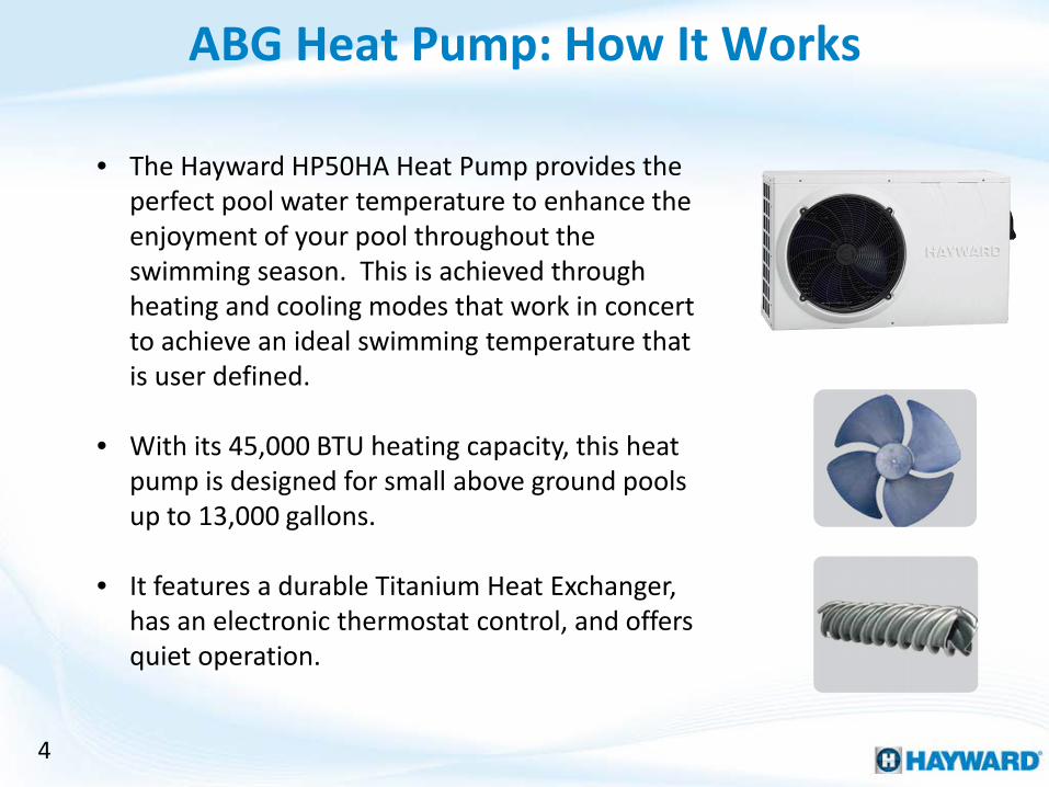
ABG Heat Pump: How It Works
• The Hayward HP50HA Heat Pump provides the perfect pool water temperature to enhance the enjoyment of your pool throughout the swimming season. This is achieved through heating and cooling modes that work in concert to achieve an ideal swimming temperature that is user defined.
• With its 45,000 BTU heating capacity, this heat pump is designed for small above ground pools up to 13,000 gallons.
• It features a durable Titanium Heat Exchanger, has an electronic thermostat control, and offers quiet operation.
4
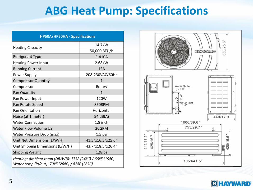
ABG Heat Pump: Specifications
HP50A/HP50HA - Specifications
Heating Capacity 14.7kW
50,000 BTU/h Refrigerant Type R-410A Heating Power Input 2.68kW Running Current 12A Power Supply 208-230VAC/60Hz Compressor Quantity 1 Compressor Rotary Fan Quantity 1 Fan Power Input 120W Fan Rotate Speed 850RPM Fan Orientation Horizontal Noise (at 1 meter) 54 dB(A) Water Connection 1.5 inch Water Flow Volume US 20GPM Water Pressure Drop (max) 1.5 psi Unit Net Dimensions (L/W/H) 41.5"x16.5"x25.6" Unit Shipping Dimensions (L/W/H) 43.7"x18.5"x26.4" Shipping Weight 128lbs Heating: Ambient temp (DB/WB): 75ºF (24ºC) / 66ºF (19ºC) Water temp (in/out): 79ºF (26ºC) / 82ºF (28ºC)
5
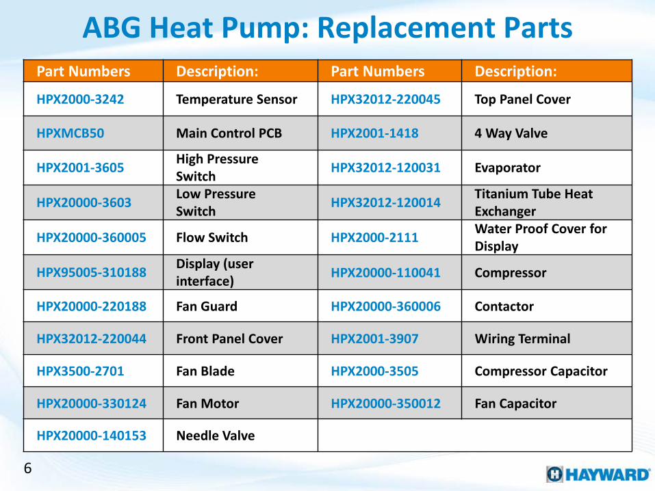
ABG Heat Pump: Replacement Parts Part Numbers Description: Part Numbers Description:
HPX2000-3242 Temperature Sensor HPX32012-220045 Top Panel Cover
HPXMCB50 Main Control PCB HPX2001-1418 4 Way Valve
HPX2001-3605 High Pressure Switch HPX32012-120031 Evaporator
HPX20000-3603 Low Pressure Switch HPX32012-120014 Titanium Tube Heat
Exchanger
HPX20000-360005 Flow Switch HPX2000-2111 Water Proof Cover for Display
HPX95005-310188 Display (user interface) HPX20000-110041 Compressor
HPX20000-220188 Fan Guard HPX20000-360006 Contactor
HPX32012-220044 Front Panel Cover HPX2001-3907 Wiring Terminal
HPX3500-2701 Fan Blade HPX2000-3505 Compressor Capacitor
HPX20000-330124 Fan Motor HPX20000-350012 Fan Capacitor
HPX20000-140153 Needle Valve
6
Out
let W
ater
Sen
sor
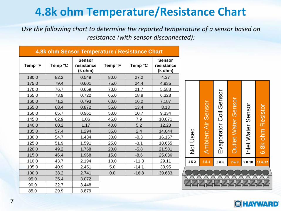
4.8k ohm Temperature/Resistance Chart
7
Use the following chart to determine the reported temperature of a sensor based on resistance (with sensor disconnected):
4.8k ohm Sensor Temperature / Resistance Chart
Temp °F Temp °C Sensor
resistance (k ohm)
Temp °F Temp °C Sensor
resistance (k ohm)
180.0 82.2 0.549 80.0 27.2 4.37 175.0 79.4 0.601 75.0 24.4 4.935 170.0 76.7 0.659 70.0 21.7 5.583 165.0 73.9 0.722 65.0 18.9 6.328 160.0 71.2 0.793 60.0 16.2 7.187 155.0 68.4 0.872 55.0 13.4 8.18 150.0 65.7 0.961 50.0 10.7 9.334 145.0 62.9 1.06 45.0 7.9 10.671 140.0 60.2 1.17 40.0 5.2 12.23 135.0 57.4 1.294 35.0 2.4 14.044 130.0 54.7 1.434 30.0 -0.3 16.167 125.0 51.9 1.591 25.0 -3.1 18.655 120.0 49.2 1.768 20.0 -5.8 21.581 115.0 46.4 1.968 15.0 -8.6 25.036 110.0 43.7 2.194 10.0 -11.3 29.11 105.0 40.9 2.451 5.0 -14.1 33.95 100.0 38.2 2.741 0.0 -16.8 39.683 95.0 35.4 3.072 90.0 32.7 3.448 85.0 29.9 3.879
6.8k
ohm
Res
isto
r
Inle
t Wat
er S
enso
r
Eva
pora
tor C
oil S
enso
r
Am
bien
t Air
Sen
sor
Not
Use
d
1 & 2 3 & 4 5 & 6 7 & 8 9 & 10 11 & 12

Display Functions & Descriptions
8
LED Display: Use for readings, set points, & timers
Use for toggling heater modes
and setting parameters
Use to set when schedule
ends
Use to set system time
Use to set when schedule
starts
Use to toggle heat pump
active/inactive
Use for toggling Metric vs. US
Standard Increase
parameter
Decrease parameter
HP50HA ABG Heat Pump How To:

Follow these steps instructions to activate/deactivate the heat pump OR to toggle between Auto, Heat, and Cool modes.
How To: Toggling ON/OFF & Mode
10
To activate the heat pump, press & release the power button (DO NOT HOLD). The power LED should appear
in Red when the heat pump is activated.
Press Power Button
To deactivate the heat pump, press & release the power button (DO NOT HOLD). The power LED should
go out when the heat pump is deactivated.
Press Power Button
Heat Pump Active Heat Pump Inactive
Press the ‘MODE’ button to toggle between: Auto, Heat, and Cool. While toggling the “MODE” button the temperature should appear on the display.
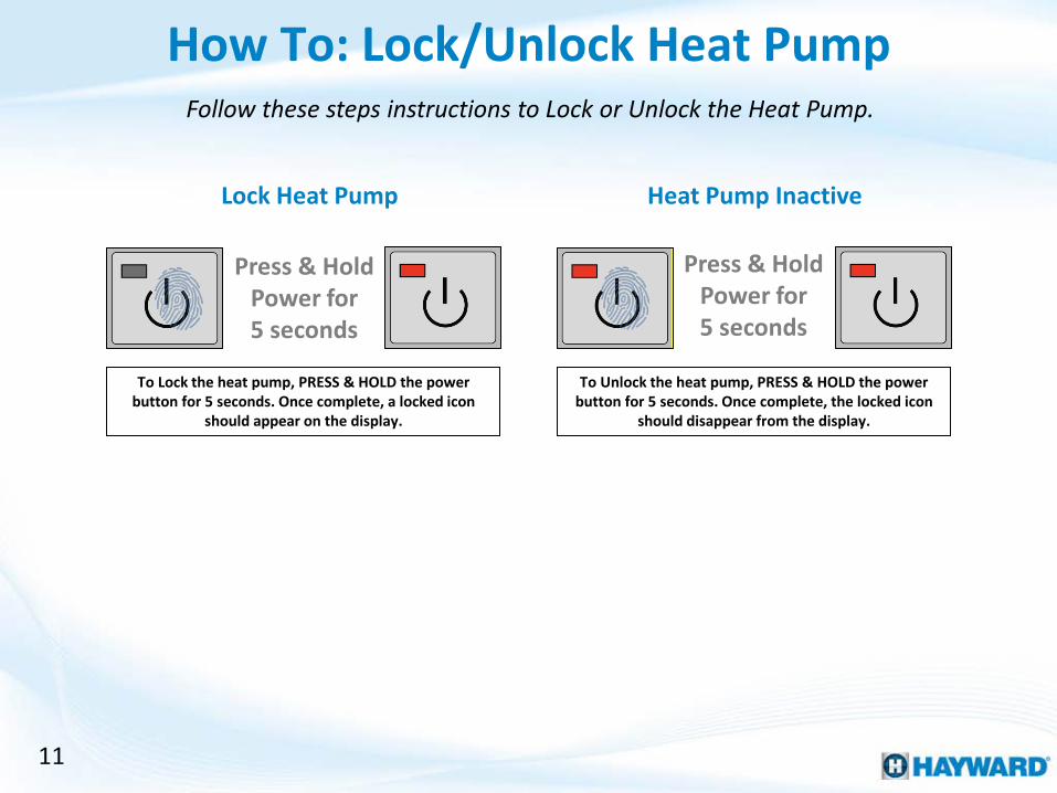
Follow these steps instructions to Lock or Unlock the Heat Pump.
How To: Lock/Unlock Heat Pump
11
To Lock the heat pump, PRESS & HOLD the power button for 5 seconds. Once complete, a locked icon
should appear on the display.
Press & Hold Power for 5 seconds
To Unlock the heat pump, PRESS & HOLD the power button for 5 seconds. Once complete, the locked icon
should disappear from the display.
Lock Heat Pump Heat Pump Inactive
Press & Hold Power for 5 seconds

Follow these steps to set the pool temperature.
How To: Set Pool Temperature
12
Step 1
Verify the heater’s power LED is illuminated, and put the heater is the desired mode.
Using the up and down arrows adjust the heater to the desired temperature.
Step 2
Once desired temperature has been set, press the “MODE” button to save set point.
Step 3
Note: Step 3, IF you wish to cancel the set point change, press the Power button instead of “MODE”.
Press the “CLOCK” button, this will cause the minutes to flash.
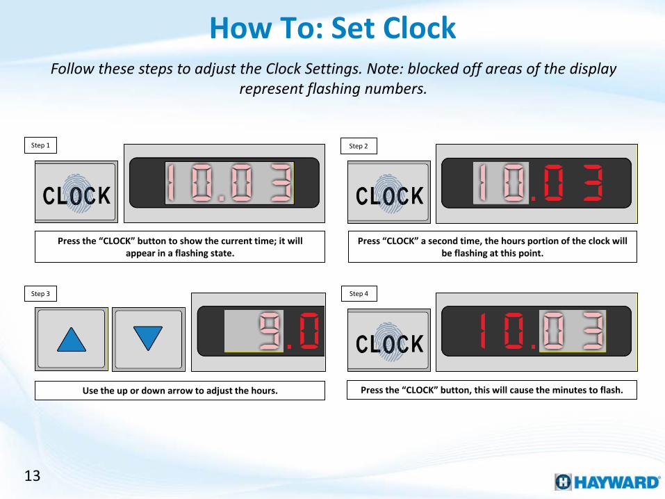
How To: Set Clock
13
Follow these steps to adjust the Clock Settings. Note: blocked off areas of the display represent flashing numbers.
Step 3 Step 4
Step 1
Press the “CLOCK” button to show the current time; it will appear in a flashing state.
Press “CLOCK” a second time, the hours portion of the clock will be flashing at this point.
Step 2
Use the up or down arrow to adjust the hours.

How To: Set Clock (cont.)
14
Note: blocked off areas of the display represent flashing numbers.
Step 5
Use the up or down arrow to adjust the hours. Press “CLOCK” a final time to save and exit.
Step 6
Note: Step 6, IF you wish to cancel all changes, press the Power button instead of “CLOCK”.

Step 1
Press the “TIMER ON” button, this will cause minutes to flash.
How To: Set Timer ON/OFF
15
Follow these steps to adjust the ON/OFF timer. Note: blocked off areas of the display represent flashing numbers.
Step 3 Step 4
Press the “TIMER ON” button to show the start time; it will appear in a flashing state.
Press “TIMER ON” a second time, the hours portion of the start time will be flashing at this point.
Step 2
Use the up or down arrow to adjust the hours.
16
Step 5
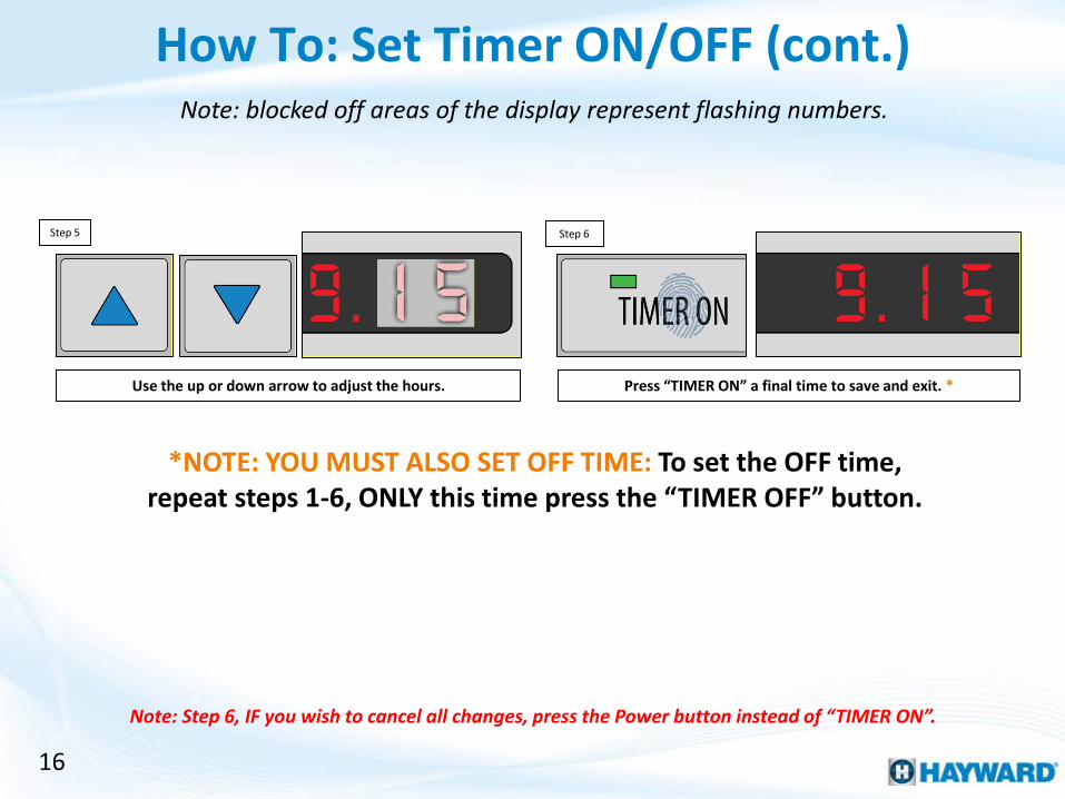
Use the up or down arrow to adjust the hours. Press “TIMER ON” a final time to save and exit. *
Step 6
Note: Step 6, IF you wish to cancel all changes, press the Power button instead of “TIMER ON”.
How To: Set Timer ON/OFF (cont.) Note: blocked off areas of the display represent flashing numbers.
*NOTE: YOU MUST ALSO SET OFF TIME: To set the OFF time, repeat steps 1-6, ONLY this time press the “TIMER OFF” button.

Step 3
NOTE: At this point the Timer ON LED should have gone out & the display should return to the temperature reading. *
Step 1
How To: Cancel Existing Timers
17
Follow these steps to cancel the ON/OFF timer. Note: blocked off areas of the display represent flashing numbers.
Press the “TIMER ON” button to show the start time; it will appear in a flashing state.
Press & release the power button to cancel this ON timer (DO NOT HOLD DOWN).
Step 2
*NOTE YOU MUST ALSO CANCEL OFF TIME: repeat steps 1-3, ONLY this time press the “TIMER OFF” button.

18
Follow these steps when attempting to test a capacitor (using an multi-meter).
How To: Check A Capacitor (multi-meter)
First, document how wires are attached then remove all wires from capacitor.
Set multi-meter to ohms (60K range OR highest possible option if less than 60K).
Touch one probe to one set of terminals, and while looking at the meter touch the other set.
For a slit second, the meter should show are reading and return to OL or blank.
Step 1
Step 4
Step 3
Step 2
Step 5a For a slit second, the meter should show are reading and return to OL or blank.
Step 5b If the meter’s display never shows a reading, then the capacitor needs to be replaced.
Visual Clues Warranting a Capacitor Replacement
If capacitor is swollen.
If any of the posts/terminals are loose.
More than one instance of a burned wire connecting to a capacitor

HP50HA ABG Heat Pump Troubleshooting

20
Error Code: P01,02,04,05
Locate temperature
sensors
Remove selected sensor from wire locks
Ohm sensor comparing values to Temperature / Resistance Chart
(pg. 7)
1. Error Code: P01, P02, P04 or P05
Power down Heat Pump
YES Is sensor within
expected range?
NO
Replace Sensor: HPX2000-3242
Replace Main PCB: HPXMCB50
Position (left>right)
Purpose ERROR
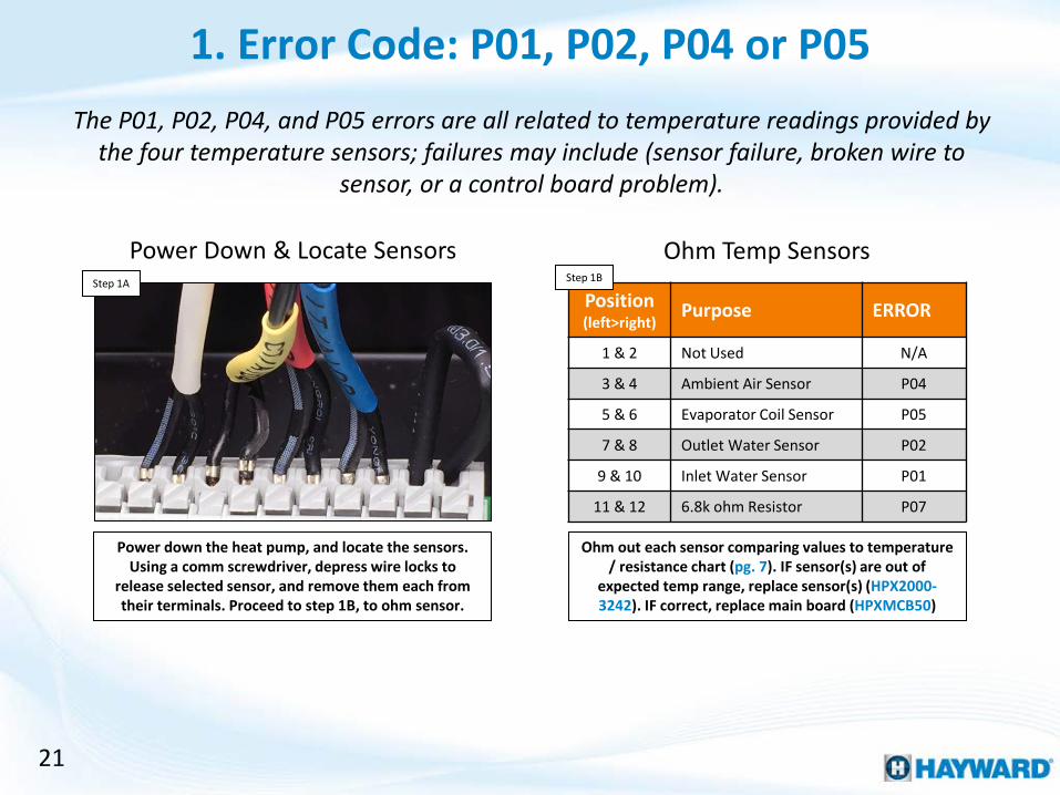
1 & 2 Not Used N/A
3 & 4 Ambient Air Sensor P04
5 & 6 Evaporator Coil Sensor P05
7 & 8 Outlet Water Sensor P02
9 & 10 Inlet Water Sensor P01
11 & 12 6.8k ohm Resistor P07
21
The P01, P02, P04, and P05 errors are all related to temperature readings provided by the four temperature sensors; failures may include (sensor failure, broken wire to
sensor, or a control board problem).
Power down the heat pump, and locate the sensors. Using a comm screwdriver, depress wire locks to
release selected sensor, and remove them each from their terminals. Proceed to step 1B, to ohm sensor.
Ohm out each sensor comparing values to temperature / resistance chart (pg. 7). IF sensor(s) are out of
expected temp range, replace sensor(s) (HPX2000-3242). IF correct, replace main board (HPXMCB50)
Power Down & Locate Sensors Step 1A Step 1B
Ohm Temp Sensors
1. Error Code: P01, P02, P04 or P05
22
2. Error Code: P07
Error Code: P07
Verify resistor is secured to main control
board
Is resistor secured?
Power down Heat Pump
YES
NO
Replace Main PCB: HPXMCB50
Secure resistor, then
retest
YES
NO
Did error clear?
Problem solved
Verify resistor is measuring at 6.8k
ohm (+/-.5)
Is 6.8k ohm resistor in
range?
YES
NO
Replace resistor: (field supplied)

23
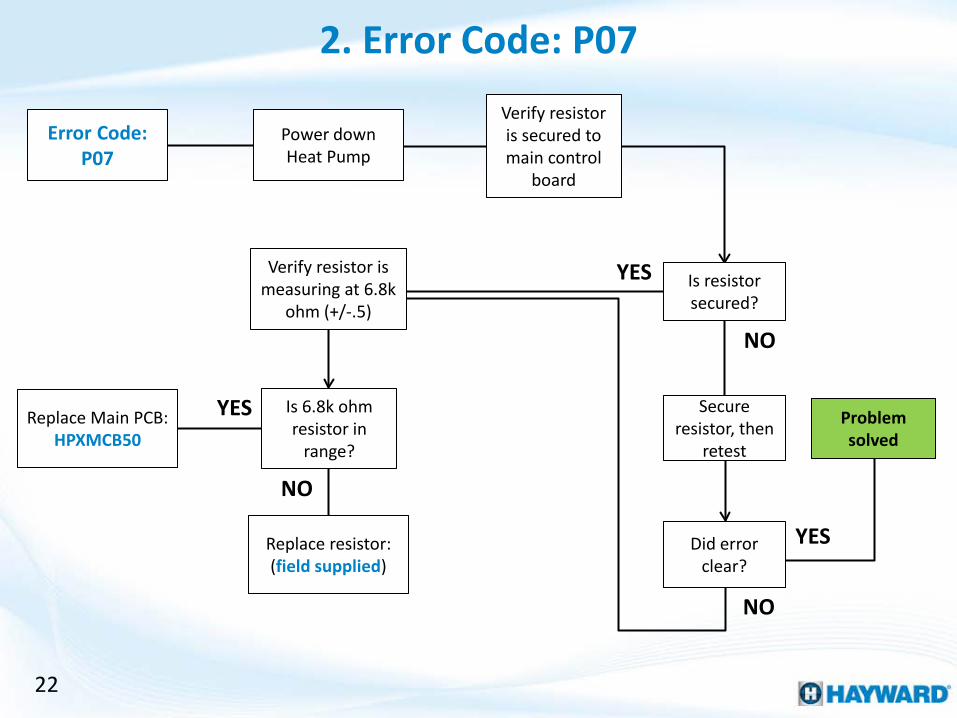
Locate and test the 6.8k Ohm resistor on the main control PCB. If the resistor is out of range, replace it, otherwise replace the main control PCB.
Power down the heat pump, and locate the resistor. Verify it is secured to the main control PCB. IF not,
secure the resistor and retest. IF secured, proceed to step 2B.
Measure the resistor, verifying 6.8k ohms (+/-.5). IF the resistance is correct, replace the main control PCB
(HPXMCB50). IF incorrect, replace the 6.8k ohm resistor (Field Supplied).
Power Down & Locate Resistor Step 2A Step 2B
Measure Resistance
2. Error Code: P07
NOTE: 6.8k ohm resistor is not reading with +/-.5, then replace it with a locally sourced 6.8k ohm resistor.

24
Attach gauge manifold to
high side
Replace switch: HPX2001-3605
3. Error Code: E01
Does error clear when heat pump is not running?
Power down Heat Pump
Inspect pressure switch
wires
NO
YES
Error Code: E01
Remove pressure switch wires & test
switch for resistance
Does the switch have resistance?
YES
NO
Repair/replace Field Supplied
Are wires damaged?
Replace Main PCB: HPXMCB50
YES
NO
During operation, does pressure exceed
580PSI?
Verify pump speed, increase
if necessary
YES
NO Is low pressure side dropping
rapidly?
YES
Replace filter dryer:
(field supplied)
NO
NO Remove refrigerant,
evacuate to 500 microns, recharge with 3.1lbs
R-410A
Replace switch: HPX2001-3605

25
An Error Code: E01 relates to a problem detected on the high refrigerant pressure side. This could be caused by a problem with the pressure switch, pressure switch wiring, control board PCB, the water supply, the filter dryer, or the Heat Pumps refrigerant
charge.
To isolate an E01 error, first verify whether the error clears when the heat pump is not running. IF the error
clears, go to 3D. IF the error does not clear, jump to step 3B.
Power down heat pump, disconnect high pressure switch wires & measure switch for resistance. IF
resistance is identified, replace switch (HPX2001-3605). IF no resistance, go to step 3C.
Does Error Clear? Step 3A Step 3B
Power Down & Test Pressure Switch
3. Error Code: E01

26
If pressure switch wires are damaged then they will need to be repaired or replaced, as this will cause issues between the control board and the pressure switch.
If pressure switch wires are damaged, this will affect how the control board interacts with the switch. IF
wires are damaged, repair/replace (Field Supplied). IF not damaged, replace main control PCB (HPXMCB50).
Attach high pressure manifold gauge. IF during operation the pressure exceeds 580PSI, go to step 3E. IF
it does not exceed 580PSI, replace pressure switch (HPX2001-3605).
Inspect Pressure Switch Wires Step 3C Step 3D
Verify High Pressure Side
NOTE: A pressure gauge adaptor (1/4” male SAE to 5/16” female SAE) must be field supplied to test the high and low pressure manifolds.
3. Error Code: E01 (cont.)

Recharge Specifications
Evacuate to 500 microns
Recharge with 3.1lbs of R-410A
27
Overcharging the Heat Pump can also cause an Error Code E01. If overcharged recover refrigerant from the heat pump, evacuate to 500 microns, and recharge with
3.1lbs R-410A refrigerant.
Verify flow through heater is minimum 20GPM, correct if necessary. Monitor the low pressure side. IF low
pressure is falling rapidly, while high pressure increases, replace filter dryer (field supplied). IF not, go
to step 3F.
If the heat pump is overcharged this can cause an E01 error code. Power heat pump down and remove
refrigerant. Evacuate system to 500 microns. Then recharge with 3.1lbs of R-410A. IF this does not correct
the problem, contact support (908) 355-7995.
Pump Speed & Low Pressure Side Step 3E Step 3F
Recharge Heat Pump
3. Error Code: E01 (cont.)

28
Attach gauge manifold to
low side
4. Error Code: E02
Does error clear when heat pump is not running?
YES
NO
Error Code: E02
Repair/replace wiring:
Field Supplied
Replace Main PCB:
HPXMCB50
While dormant, is pressure
above 25PSI?
System is low on refrigerant.
Find leak. Recover any remaining refrigerant.
NO
Repair leaks, evacuate to 500 microns &
recharge with 3.1lbs R-410A
YES
Attach gauge manifold to
low side
Remove pressure switch wires & test
switch for resistance
Does the switch have resistance?
YES Replace switch: HPX20000-3603
NO Inspect
pressure switch wires
Are wires damaged?
YES
NO
During operation, is
pressure above 3PSI?
YES
Leak test, recover any remaining refrigerant
Repair leaks, evacuate to 500
microns & recharge with 3.1lbs R-410A
Is fan running?
NO
YES
NO
Go to Section 2 (next page)

29
4. Error Code: E02
Ensure fan has 240VAC (on call for heat/cool)
Section 2: (Fan not running)
Is 240VAC present?
NO
Replace Main PCB: HPXMCB50
YES
Check fan for obstructions, if
present, shut down & remove
obstructions
Remove fan wires and
measure for resistance
Red & blue = 83ohms Blue & black = 203ohms Red & black = 121ohms, are these values correct?
YES
NO
Replace fan motor: HPX2000-330124
Test fan capacitor (pg.
18), is capacitor good?
YES
Contact tech support:
(908) 355-7995
Replace capacitor: HPX2000-350012
NO

30
While the heat pump is in its dormant (not running) state, the low side pressure should read at least 25PSI.
To isolate an E02 error, first verify whether the error clears when the heat pump is not running. IF the error does not clear, go to 4B. IF error clears, jump ahead to
step 4F.
Attach low pressure manifold gauge. With the heat pump OFF, verify the pressure is above 25PSI. IF the
pressure is below 25PSI, go to 4C. IF above 25PSI, jump ahead to step 4D.
Step 4A Step 4B
Verify Low Pressure Side
4. Error Code: E02
Does Error Clear?
NOTE: A pressure gauge adaptor (1/4” male SAE to 5/16” female SAE) must be field supplied to test the high and low pressure manifolds.

Recharge Specifications
Evacuate to 500 microns
Recharge with 3.1lbs of R-410A
31
If the heat pump does not have 25PSI of pressure on the low pressure side, while dormant (not running), then it likely has a leak.
Test the heat pump for leaks & repair as needed. Power heat pump down and recover any remaining
refrigerant. Repair leak. Evacuate to 500 microns. Then recharge with 3.1lbs of R-410A. IF this does not correct
the problem, contact support (908) 355-7995.
Power down heat pump, disconnect low pressure switch wires & measure switch for resistance. IF
resistance is identified, replace switch (HPX2001-3605). IF no resistance, proceed to step 4E,
to inspect pressure switch wires.
Leak Test & Recharge Heat Pump Step 4C Step 4D
4. Error Code: E02 (cont.)
Power Down & Test Pressure Switch

32
If pressure switch wires are damaged, this will affect how the control board interacts with the switch. IF
wires are damaged, repair/replace (field supplied). IF not damaged, replace main control PCB (HPXMCB50).
Attach low pressure manifold gauge. With the heat running, verify the pressure is at least 3PSI. IF pressure
is below 3PSI, go to 4G. IF equal to or above 3PSI, go back to step 4D.
Inspect Pressure Switch Wires Step 4E Step 4F
4. Error Code: E02 (cont.)
Verify Low Pressure Side
While the heat pump is running, the low side pressure should read at least 3PSI.

Recharge Specifications
Evacuate to 500 microns
Recharge with 3.1lbs of R-410A
33
If the fan is not running, this will affect the low side pressure. Verify whether the fan is running. IF the fan is
running go to step 4H. IF not running, jump ahead to step 4I.
Test the heat pump for leaks & repair as needed. Power heat pump down and recover remaining refrigerant. Repair leak. Evacuate to 500 microns. Then recharge
with 3.1lbs of R-410A. IF this does not correct the problem, contact support (908) 355-7995.
During Operation Inspect Fan Step 4G Step 4H
4. Error Code: E02 (cont.)
Leak Test & Recharge Heat Pump
If the fan is not running when the heat pump is calling for heat/cool, this could affect the low side pressure. Verify whether the fan is running when calling for heat/cool.
34
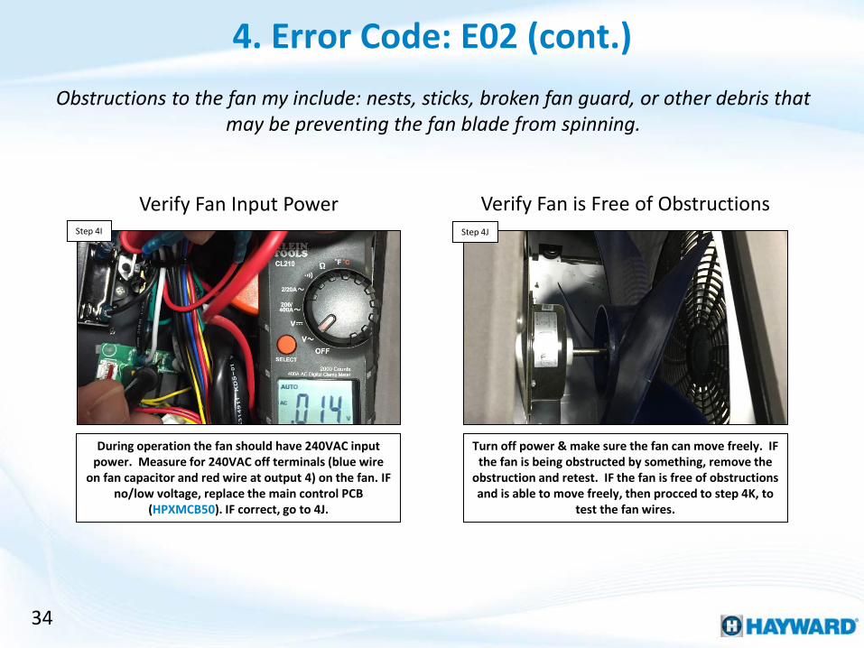
During operation the fan should have 240VAC input power. Measure for 240VAC off terminals (blue wire
on fan capacitor and red wire at output 4) on the fan. IF no/low voltage, replace the main control PCB
(HPXMCB50). IF correct, go to 4J.
Turn off power & make sure the fan can move freely. IF the fan is being obstructed by something, remove the
obstruction and retest. IF the fan is free of obstructions and is able to move freely, then procced to step 4K, to
test the fan wires.
Verify Fan Input Power Step 4I Step 4J
4. Error Code: E02 (cont.)
Verify Fan is Free of Obstructions
Obstructions to the fan my include: nests, sticks, broken fan guard, or other debris that may be preventing the fan blade from spinning.

35
Isolate the fan and measure resistance across the wires. They should be: between red & blue (83ohms), blue &
black (203ohms), & red & black (121ohms). IF correct go to 4L. IF incorrect, replace the fan motor (HPX2000-
330124).
Disconnect wires to the fan capacitor and measure for resistance (pg. 18). IF capacitor tests bad, then replace the fan capacitor (HPX2000-350012). IF correct contact
tech support for further assistance (908) 355-7995.
Disconnect & Test Fan Motor Step 4K Step 4L
4. Error Code: E02 (cont.)
Test Fan Capacitor
To test the fan motor, isolate the motor wires and measure resistance across red & blue (83ohms), blue & black (203ohms), and red & black (121ohms).

36
Verify water is flowing at pool
return
5. Error Code: E03
Verify the pump is running
YES
Check skimmer basket & filter pressure, clean
as needed
Check flow switch
orientation
Is flow switch installed
correctly?
After turning on the pump,
does error persist?
Error Code: E03
Shut down pump, drain
lines & reinstall switch
correctly
Problem solved
NO
YES
NO
If bypass is open, slowly
close to determine if error clears
Did the error clear while
closing bypass?
Too much water was
bypassing the heat pump
YES
NO Isolate flow
switch wires & test for continuity
through switch with pump
running
Does the switch have continuity?
YES
NO
Replace Main PCB: HPXMCB50
Replace Flow Switch: HPX20000-360005
Problem solved

37
Error Code 03 is reporting a flow error. Verify the pump is not only on and running but circulating water through the heat pump before proceeding.
Verify the pump is on and water is passing through the heat pump. Finally, check the pool return to make sure water is circulating in the pool. IF correct, go to step 5B.
IF incorrect, resolve & retest.
Verify Flow Step 5A Step 5B
Verify the flow switch is mounted in the correct orientation. IF the flow switch is installed properly, go to 5C. Otherwise, turn off pump, correct orientation,
and retest.
Verify Flow Switch Orientation
5. Error Code: E03

38
Check the skimmer, pump basket, filter pressure. Clean as needed. If the error clears after cleaning the filter, note the current pump speed and filter for future reference.
Inspect the skimmer, filter pressure, & pump basket. Clean as needed. IF after cleaning the error persists
continue to step 5D. If the error clears, make note of the filter pressure and pump speed.
Check Skimmer & Filter Pressure Step 5C Step 5D
If the bypass is open, slowly close the bypass, checking to see of this clears the E03. The bypass may be causing
the flow error. IF the error clears, fully close or leave the bypass in its current position. IF not, go to 5E.
Slowly Close Bypass
5. Error Code: E03 (cont.)

39
When the flow requirements of the heat pump are satisfied, the flow switch should register continuity, and it should report as open at insufficient flow.
Isolate the flow switch (disconnecting the wires from the control board). With the pump running, test for
continuity through the switch. IF no continuity, replace the switch (HPX20000-360005). IF continuity is present,
replace the main control board (HPXMCB50)
Isolate Flow Switch & Test Step 5E
5. Error Code: E03 (cont.)

6. Error Code: E06
Error Code: E06
Test inlet & outlet water temp sensors against 4.8k
ohm chart (pg. 7)
Expected water differential
between inlet & outlet is: 3.5°F
Replace defective temp sensor(s): HPX2000-3242
Based on chart, are either temp sensors
out of range?
YES
NO
Close bypass slowly,
monitoring the temperature differential
between the inlet & outlet
Did partially or fully closing bypass correct
the problem?
YES
NO
Problem solved
Replace Main PCB: HPXMCB50

41
The E06 error implies that the temperature differential between the inlet and outlet water sensors is greater than 58°F; however the expected differential between these
sensors should be closer to 3.5°F.
Following the chart (pg. 7), verify whether the inlet & outlet water temperature sensors are reading
accurately. IF they are, go to step 6B. IF not, replace defective sensor(s) (HPX2000-3242).
Test Inlet & Outlet Temp Sensors Step 6A Step 6B
The expected differential, between the inlet and outlet is 3.5°F. Slowly close the bypass, monitoring the
differential. IF closing the bypass does not correct the problem, replace the main PCB (HPXMCB50).
Monitor Differential (closing bypass)
6. Error Code: E06

42
Error Code: E07/E19/E29
7. Error Code: E07/E19/E29 E19: (standby mode) & implies air temp reads <32°F & water temp is
between 37°- 40°F
E29: (heating mode) & implies air temp
reads <32°F & water temp < 36°F
Is error code: E19?
YES
NO
Using 4.8k ohm chart (pg. 7), measure both
air and water temp sensors
Replace defective temp sensor(s): HPX2000-3242
Based on chart, are either temp sensors
out of range?
YES
NO
Replace Main PCB: HPXMCB50
Is error code: E29?
NO
YES
E07: (cooling mode) & implies air temp reads <32°F & water temp
< 40°F

43
Error Codes: E07, E19, & E29 all refer to different versions of freeze protection and are based on reported temperature reading by the ambient air temp sensor and inlet
water temp sensor.
IF the error code is an E07, go to step 7B. IF the error code is an E19, jump to step 7C. IF the error code is
reporting as a E29, then jump ahead to step 7D.
Which Error Code Step 7A Step 7B
An E07 Error Code will appear in cooling mode & implies air temp reads <32°F & water temp < 40°F.
Jump to step 7E to verify sensors.
Error Code: E07
7. Error Code: E07/E19/E29
Step 7B
Step 7C
Step 7D

44
An E19 Error Code will appear in standby mode & implies air temp reads <32°F & water temp is between
37°- 40°F. Jump to step 7E to verify sensors.
Error Code: E19 Step 7C
An E29 Error Code will appear in heating mode & implies air temp reads <32°F & water temp < 36°F.
Jump to step 7E to verify sensors.
Error Code: E29 Step 7D
Error Codes: E07, E19, & E29 all refer to different versions of freeze protection and are based on reported temperature reading by the ambient air temp sensor and inlet
water temp sensor.
7. Error Code: E07/E19/E29 (cont.)

45
Either the sensor(s) is/are causing the problem or the problem resides in the main control board.
Following the chart (pg. 7), verify whether the air & inlet water temperature sensors are reading accurately.
IF they are not, replace defective sensor(s) (HPX2000-3242). IF they are, replace main PCB (HPXMCB50).
Test the Air & Inlet Temp Sensors Step 7E
7. Error Code: E07/E19/E29 (cont.)

46
Error Code: E08
8. Error Code: E08 Connect a new Display to the main control
board
Did the E08 go away?
Replace Main PCB: HPXMCB50
Replace display: HPX95005-310188
YES
NO

47
An Error Code: E08 refers to a communication error between the display (user interface) and the main control board.
Swap display (user interface) with a new display board (HPX95005-310188). IF the problem goes away, keep
the new display board on. IF the problem persists, replace the main control board (HPXMCB50).
Replace Display Step 8A
8. Error Code: E08
Reading Serial Numbers
48
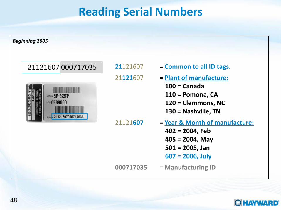
Beginning 2005
21121607 = Common to all ID tags.
21121607 = Plant of manufacture: 100 = Canada 110 = Pomona, CA 120 = Clemmons, NC 130 = Nashville, TN
21121607 = Year & Month of manufacture: 402 = 2004, Feb 405 = 2004, May 501 = 2005, Jan 607 = 2006, July
000717035 = Manufacturing ID
21121607 000717035