HP250II and HP250 Butterfly Valves - Henry Pratt Company · Body Styles: End connections Flanged...
12
Engineering Creative Solutions for Fluid Systems Since 1901 HP250II ® and HP250 ™ Butterfly Valves
Transcript of HP250II and HP250 Butterfly Valves - Henry Pratt Company · Body Styles: End connections Flanged...
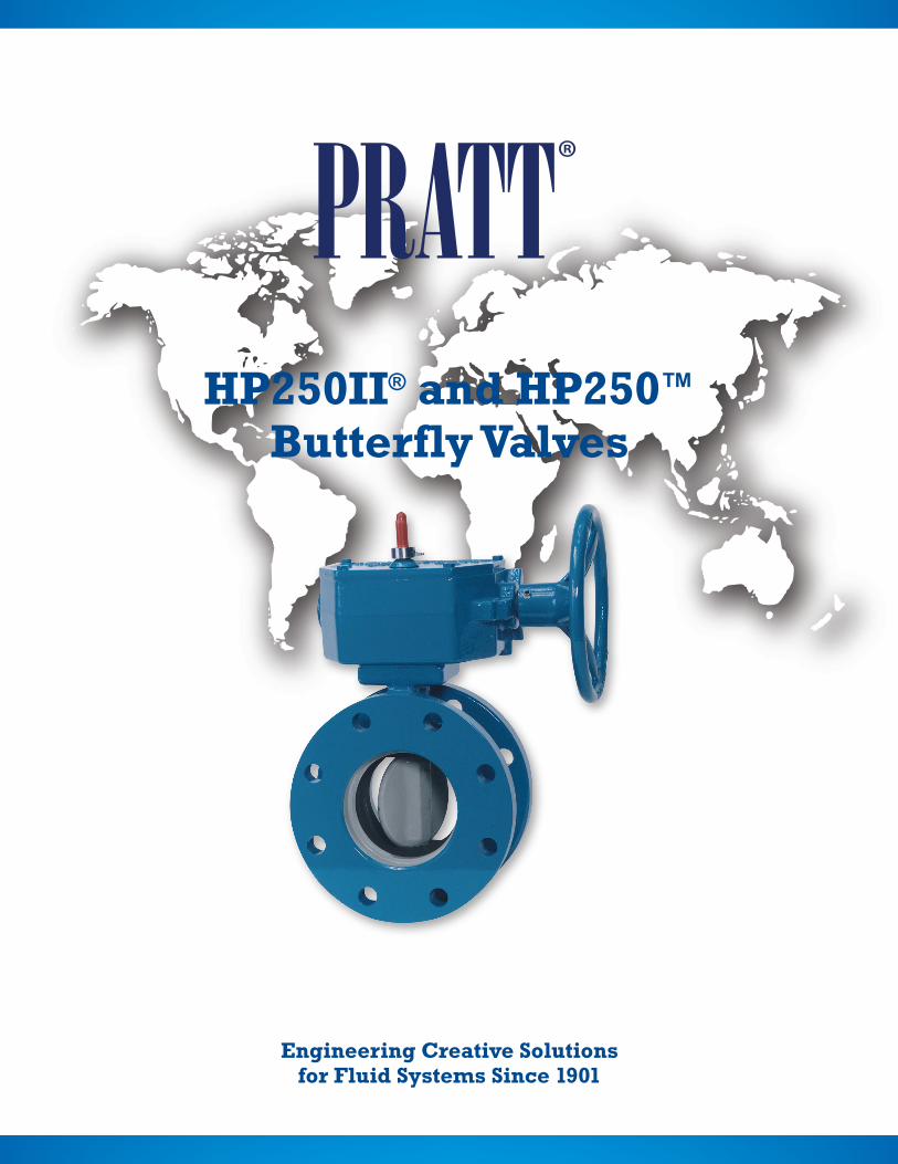
Engineering Creative Solutionsfor Fluid Systems Since 1901
HP250II® and HP250™
Butterfly Valves
Table of Contents
Pratt® HP250II®
Scope of Line .............................................................................................................................................................................................1
Design and Construction Details .......................................................................................................................................................1
Pipe Mating Chart ....................................................................................................................................................................................1
Features and Benefits ............................................................................................................................................................................2
E-LOK® Seating System ........................................................................................................................................................................2
Seat on Body Design Advantage .......................................................................................................................................................3
HP250II Suggested Specification .....................................................................................................................................................4
Dimensional Data ................................................................................................................................................................................4-6
Pratt® HP250™
Scope of Line .............................................................................................................................................................................................7
HP250 Suggested Specification ........................................................................................................................................................7
Dimensional Data......................................................................................................................................................................................8
401 South Highland AvenueAurora, Illinois 60506-5563
www.henrypratt.comphone: 630.844.4000
Email: [email protected]
Copyright © 2017 Henry Pratt Company, LLC. All Rights Reserved.
The trademarks, logos and service marks displayed in this document herein are the property of Henry Pratt Company, LLC, its affiliates or other third parties. Products above marked with a section symbol (§) are subject to patents or patent applications. For details, visit www.mwppat.com. These products are intended for use in potable water or wastewater applications. Please contact your Henry Pratt Company Sales or Customer Service Representative concerning any other application(s).
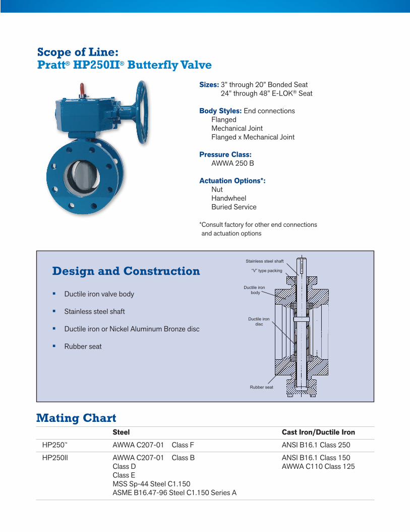
Sizes: 3” through 20” Bonded Seat 24” through 48” E-LOK® Seat
Body Styles: End connections Flanged Mechanical Joint Flanged x Mechanical Joint
Pressure Class: AWWA 250 B Actuation Options*: Nut Handwheel Buried Service
* Consult factory for other end connections and actuation options
Design and Construction
• Ductile iron valve body
• Stainless steel shaft
• Ductile iron or Nickel Aluminum Bronze disc
• Rubber seat
Mating Chart Steel Cast Iron/Ductile Iron
HP250™ AWWA C207-01 Class F ANSI B16.1 Class 250
HP250II AWWA C207-01 Class B ANSI B16.1 Class 150 Class D AWWA C110 Class 125 Class E MSS Sp-44 Steel C1.150 ASME B16.47-96 Steel C1.150 Series A
Stainless steel shaft
“V” type packing
Ductile iron disc
Rubber seat
Ductile iron body
Scope of Line: Pratt® HP250II® Butterfly Valve
Feature
• Higher Pressures
• Wide Size Range
• Low Seating/Unseating Torques
• Unique Disc Design
• Adjustable/Replaceable Seat on 24” and larger
• Choice of Valve Ends
• Actuators and Accessories
Benefit
• Working pressures to 250 psi with temperatures to 150° F.
• Available in sizes 3” - 72” (flanged ends); 6” - 48” (mechanical joint ends).
• Increases seat life and reduces actuator size.
• Provides more strength, less weight, and greater free-flow area than conventional disc designs.
• E-LOK® design retains seat in body without metal hardware. If adjustable or replacement is required, both can be done in the field utilizing simple hand tools.
• Flange and Mechanical Joint. Flanges are in full accordance with ANSI B16.1, Class 125# cast iron flanges where applicable. Mechanical joint ends conform to ANSI 21.11. For ANSI Class 250# Flange, see page 8.
• Available with manual traveling nut or worm gear, electric motor or cylinder actuators; plus full range of extensions, indicators, positioners, remote controls and other accessories.
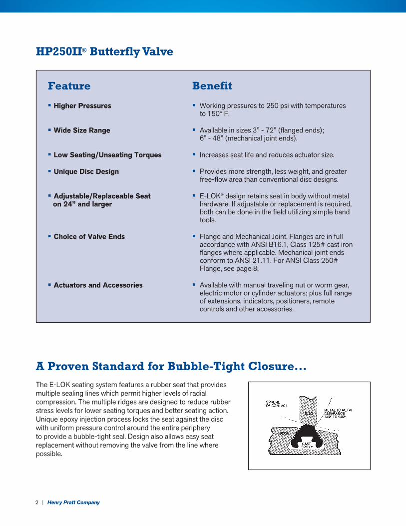
A Proven Standard for Bubble-Tight Closure...The E-LOK seating system features a rubber seat that provides multiple sealing lines which permit higher levels of radial compression. The multiple ridges are designed to reduce rubber stress levels for lower seating torques and better seating action. Unique epoxy injection process locks the seat against the disc with uniform pressure control around the entire periphery to provide a bubble-tight seal. Design also allows easy seat replacement without removing the valve from the line where possible.
HP250II® Butterfly Valve
2 | Henry Pratt Company
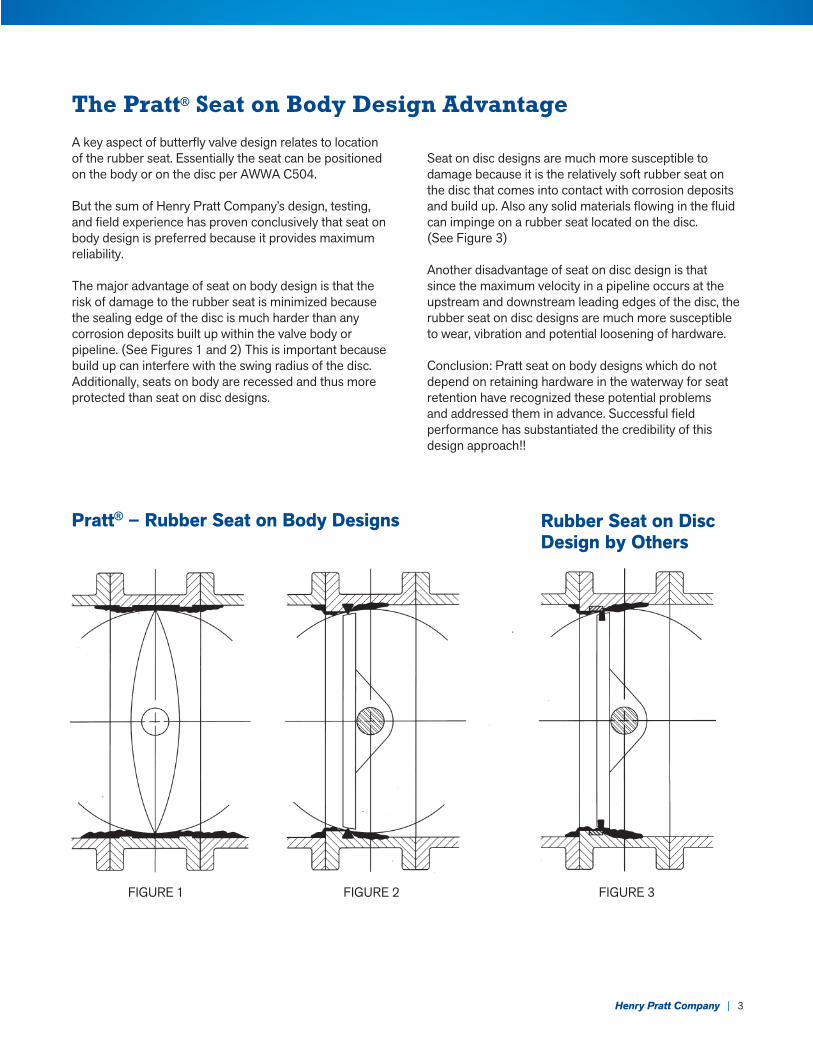
A key aspect of butterfly valve design relates to location of the rubber seat. Essentially the seat can be positioned on the body or on the disc per AWWA C504.
But the sum of Henry Pratt Company’s design, testing, and field experience has proven conclusively that seat on body design is preferred because it provides maximum reliability.
The major advantage of seat on body design is that the risk of damage to the rubber seat is minimized because the sealing edge of the disc is much harder than any corrosion deposits built up within the valve body or pipeline. (See Figures 1 and 2) This is important because build up can interfere with the swing radius of the disc. Additionally, seats on body are recessed and thus more protected than seat on disc designs.
Seat on disc designs are much more susceptible to damage because it is the relatively soft rubber seat on the disc that comes into contact with corrosion deposits and build up. Also any solid materials flowing in the fluid can impinge on a rubber seat located on the disc. (See Figure 3)
Another disadvantage of seat on disc design is that since the maximum velocity in a pipeline occurs at the upstream and downstream leading edges of the disc, the rubber seat on disc designs are much more susceptible to wear, vibration and potential loosening of hardware.
Conclusion: Pratt seat on body designs which do not depend on retaining hardware in the waterway for seat retention have recognized these potential problems and addressed them in advance. Successful field performance has substantiated the credibility of this design approach!!
The Pratt® Seat on Body Design Advantage
Pratt® – Rubber Seat on Body Designs Rubber Seat on Disc Design by Others
FIGURE 1 FIGURE 2 FIGURE 3
Henry Pratt Company | 3
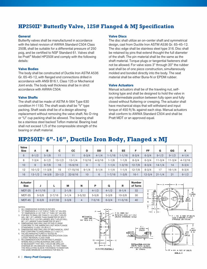
HP250II® 6”-16”, Ductile Iron Body, Flanged x MJ
GeneralButterfly valves shall be manufactured in accordance with the latest revision of AWWA Standard C504 Class 250B, shall be suitable for a differential pressure of 250 psig, and be certified to NSF Standard 61. Valves shall be Pratt® Model HP250II and comply with the following details:
Valve Bodies The body shall be constructed of Ductile Iron ASTM A536 Gr. 65-45-12, with flanged end connections drilled in accordance with ANSI B16.1, Class 125 or Mechanical Joint ends. The body wall thickness shall be in strict accordance with AWWA C504.
Valve Shafts The shaft shall be made of ASTM A-564 Type 630 condition H-1150. The shaft seals shall be “V” type packing. Shaft seals shall be of a design allowing replacement without removing the valve shaft. No O-ring or “U” cup packing shall be allowed. The bearing shall be a stainless steel backed Teflon material. Bearing load shall not exceed 1/5 of the compressible strength of the bearing or shaft material.
Valve DiscsThe disc shall utilize an on-center shaft and symmetrical design, cast from Ductile Iron ASTM A536 Gr. 65-45-12. The disc edge shall be stainless steel type 316. Disc shall be retained by pins that extend thought the full diameter of the shaft. The pin material shall be the same as the shaft material. Torque plugs or tangential fasteners shall not be allowed. For valve sizes 3” through 20” the rubber seat shall be of one piece construction, simultaneously molded and bonded directly into the body. The seat material shall be either Buna-N or EPDM rubber.
Valve Actuators Manual actuators shall be of the traveling nut, self-locking type and shall be designed to hold the valve in any intermediate position between fully open and fully closed without fluttering or creeping. The actuator shall have mechanical stops that will withstand and input torque of 450 ft/lb. against each stop. Manual actuators shall conform to AWWA Standard C504 and shall be Pratt MDT or an approved equal.
HP250II® Butterfly Valve, 125# Flanged & MJ Specification
NOTES:1. ALL DIMENSIONS SHOWN IN INCHES.2. “D” DIMENSION ±1/16” FOR 6” THRU 10” VALVES.
“D” DIMENSION ±1/8” FOR 12” THRU 20” VALVES.3. FOR BOLTS SMALLER THAN 01-3/4, BOLT HOLES
WILL BE 1/8” LARGER THAN DIAMETER OF BOLT. FOR BOLTS 01-3/4 OR LARGER, BOLT HOLES WILL BE 1/4” LARGER THAN DIAMETER OF BOLT.
4. DIMENSIONS AND DRILLING OF END FLANGE CONFORM TO THE AMERICAN CAST IRON FLANGE STANDARDS, CLASS 125 (B16.1).
5. DIMENSIONS AND DRILLING OF MECHANICAL JOINT END CONFORM TO ANSI/AWWA C111/A21/11.
6. VALVES MANUFACTURED & TESTED IN ACCORDANCE WITHE AWWA SPECIFICATION C504 LATEST REVISION, CLASS 250B.
7. RECOMMENDATION FOR MATING FLANGES: WHERE INSULATING BUSHINGS ARE USED, IT IS NECESSARY THAT BOLT HOLES BE DRILLED OVERSIZE BY AN AMOUNT EQUAL TO TWO TIMES THE INSULATING SLEEVE THICKNESS TO MAINTAIN THE SAME MINIMUM CLEARANCE FOR BOLTS.
Valve Size A B C CC D DD E EE F FF G GG X
6 6-1/2 5-1/8 11 11 6-3/4 4-1/4 1-1/16 1-1/16 8-3/4 6-3/4 9-1/2 9-1/2 4-1/4
8 7-3/4 6-1/2 13-1/2 13-1/4 7-5/16 4-5/16 1-1/8 1-1/8 8-3/4 6-3/4 11-3/4 11-3/4 4-13/16
10 9 9-7/8 16 15-9/16 9 5 1-1/4 1-3/16 12-7/8 8-3/4 14-1/4 14 6-3/4
12 10-1/2 11-3/8 19 17-15/16 9-1/4 5-1/4 1-1/4 1-1/4 12-7/8 8-3/4 17 16-1/4 6-3/4
16 13-1/2 14-3/8 23-1/2 22-9/16 10 6 1-7/16 1-3/8 16-1 12-3/4 21-1/4 21 6-1/2
Actuator Size J L M N P Q R
Number of Turns
MDT-2S 4-11/16 2 2-1/8 2 4-1/2 4-1/2 8-1/4 32
MDT-3S 5-5/8 2-7/16 3-1/4 3-5/32 5-5/8 5-3/8 10-3/8 30
MDT-45 6-3/8 2-27/32 3-3/8 4 7-5/16 6-3/4 11-5/16 40
4 | Henry Pratt Company
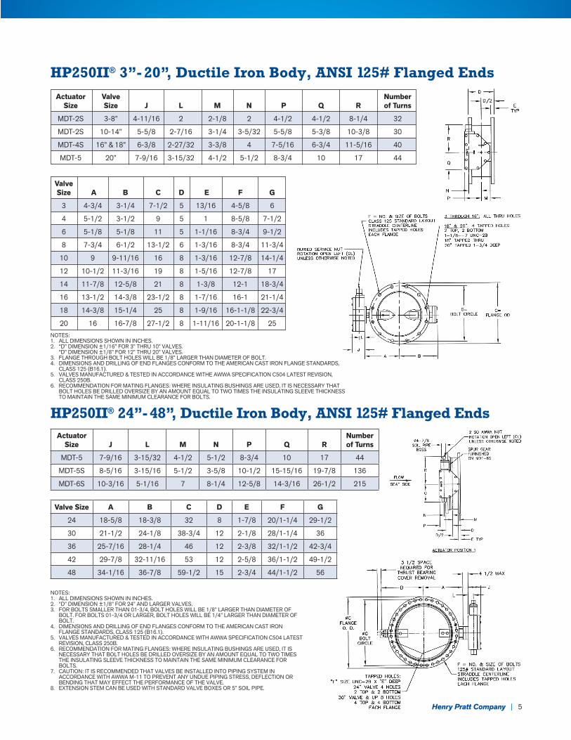
HP250II® 3”- 20”, Ductile Iron Body, ANSI 125# Flanged Ends
NOTES:1. ALL DIMENSIONS SHOWN IN INCHES.2. “D” DIMENSION ±1/16” FOR 3” THRU 10” VALVES.
“D” DIMENSION ±1/8” FOR 12” THRU 20” VALVES.3. FLANGE THROUGH BOLT HOLES WILL BE 1/8” LARGER THAN DIAMETER OF BOLT.4. DIMENSIONS AND DRILLING OF END FLANGES CONFORM TO THE AMERICAN CAST IRON FLANGE STANDARDS,
CLASS 125 (B16.1).5. VALVES MANUFACTURED & TESTED IN ACCORDANCE WITHE AWWA SPECIFICATION C504 LATEST REVISION,
CLASS 250B.6. RECOMMENDATION FOR MATING FLANGES: WHERE INSULATING BUSHINGS ARE USED, IT IS NECESSARY THAT
BOLT HOLES BE DRILLED OVERSIZE BY AN AMOUNT EQUAL TO TWO TIMES THE INSULATING SLEEVE THICKNESS TO MAINTAIN THE SAME MINIMUM CLEARANCE FOR BOLTS.
HP250II® 24”- 48”, Ductile Iron Body, ANSI 125# Flanged Ends
NOTES:1. ALL DIMENSIONS SHOWN IN INCHES.2. “D” DIMENSION ±1/8” FOR 24” AND LARGER VALVES.3. FOR BOLTS SMALLER THAN 01-3/4, BOLT HOLES WILL BE 1/8” LARGER THAN DIAMETER OF
BOLT. FOR BOLTS 01-3/4 OR LARGER, BOLT HOLES WILL BE 1/4” LARGER THAN DIAMETER OF BOLT.
4. DIMENSIONS AND DRILLING OF END FLANGES CONFORM TO THE AMERICAN CAST IRON FLANGE STANDARDS, CLASS 125 (B16.1).
5. VALVES MANUFACTURED & TESTED IN ACCORDANCE WITH AWWA SPECIFICATION C504 LATEST REVISION, CLASS 250B.
6. RECOMMENDATION FOR MATING FLANGES: WHERE INSULATING BUSHINGS ARE USED, IT IS NECESSARY THAT BOLT HOLES BE DRILLED OVERSIZE BY AN AMOUNT EQUAL TO TWO TIMES THE INSULATING SLEEVE THICKNESS TO MAINTAIN THE SAME MINIMUM CLEARANCE FOR BOLTS.
7. CAUTION: IT IS RECOMMENDED THAT VALVES BE INSTALLED INTO PIPING SYSTEM IN ACCORDANCE WITH AWWA M-11 TO PREVENT ANY UNDUE PIPING STRESS, DEFLECTION OR BENDING THAT MAY EFFECT THE PERFORMANCE OF THE VALVE.
8. EXTENSION STEM CAN BE USED WITH STANDARD VALVE BOXES OR 5” SOIL PIPE.
Actuator Size J L M N P Q R
Number of Turns
MDT-5 7-9/16 3-15/32 4-1/2 5-1/2 8-3/4 10 17 44
MDT-5S 8-5/16 3-15/16 5-1/2 3-5/8 10-1/2 15-15/16 19-7/8 136
MDT-6S 10-3/16 5-1/16 7 8-1/4 12-5/8 14-3/16 26-1/2 215
Valve Size A B C D E F G
24 18-5/8 18-3/8 32 8 1-7/8 20/1-1/4 29-1/2
30 21-1/2 24-1/8 38-3/4 12 2-1/8 28/1-1/4 36
36 25-7/16 28-1/4 46 12 2-3/8 32/1-1/2 42-3/4
42 29-7/8 32-11/16 53 12 2-5/8 36/1-1/2 49-1/2
48 34-1/16 36-7/8 59-1/2 15 2-3/4 44/1-1/2 56
Actuator Valve Number Size Size J L M N P Q R of Turns
MDT-2S 3-8” 4-11/16 2 2-1/8 2 4-1/2 4-1/2 8-1/4 32
MDT-2S 10-14” 5-5/8 2-7/16 3-1/4 3-5/32 5-5/8 5-3/8 10-3/8 30
MDT-4S 16” & 18” 6-3/8 2-27/32 3-3/8 4 7-5/16 6-3/4 11-5/16 40
MDT-5 20” 7-9/16 3-15/32 4-1/2 5-1/2 8-3/4 10 17 44
Valve Size A B C D E F G
3 4-3/4 3-1/4 7-1/2 5 13/16 4-5/8 6
4 5-1/2 3-1/2 9 5 1 8-5/8 7-1/2
6 5-1/8 5-1/8 11 5 1-1/16 8-3/4 9-1/2
8 7-3/4 6-1/2 13-1/2 6 1-3/16 8-3/4 11-3/4
10 9 9-11/16 16 8 1-3/16 12-7/8 14-1/4
12 10-1/2 11-3/16 19 8 1-5/16 12-7/8 17
14 11-7/8 12-5/8 21 8 1-3/8 12-1 18-3/4
16 13-1/2 14-3/8 23-1/2 8 1-7/16 16-1 21-1/4
18 14-3/8 15-1/4 25 8 1-9/16 16-1-1/8 22-3/4
20 16 16-7/8 27-1/2 8 1-11/16 20-1-1/8 25
Henry Pratt Company | 5
Valve Size A B C CC D DD E EE F FF G GG X
6 6-1/2 5-1/8 11 11 6-3/4 4-1/4 1-1/16 1-1/16 8-3/4 6-3/4 9-1/2 9-1/2 4-1/4
8 7-3/4 6-1/2 13-1/2 13-1/4 7-5/16 4-5/16 1-1/8 1-1/8 8-3/4 6-3/4 11-3/4 11-3/4 4-13/16
10 9 9-7/8 16 15-9/16 9 5 1-1/4 1-3/16 12-7/8 8-3/4 14-1/4 14 6-3/4
12 10-1/2 11-3/8 19 17-15/16 9-1/4 5-1/4 1-1/4 1-1/4 12-7/8 8-3/4 17 16-1/4 6-3/4
16 13-1/2 14-3/8 23-1/2 22-9/16 10 6 1-7/16 1-3/8 16-1 12-3/4 21-1/4 21 6-1/2
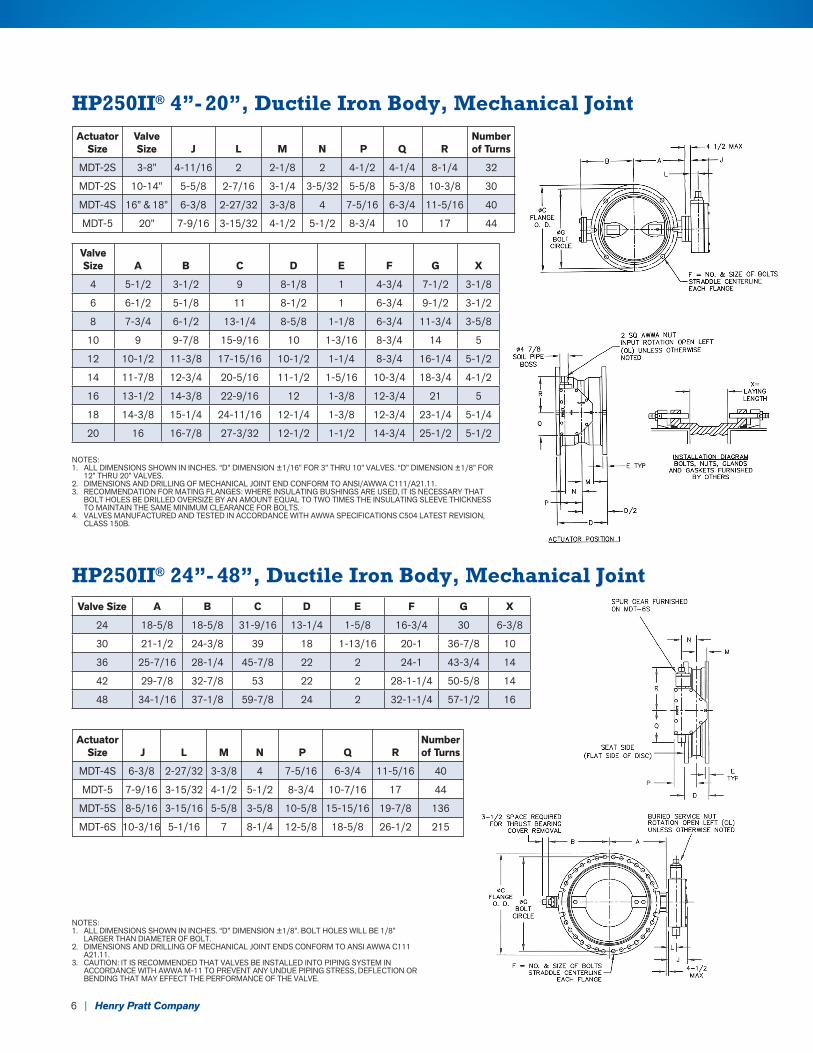
HP250II® 4”- 20”, Ductile Iron Body, Mechanical Joint
NOTES:1. ALL DIMENSIONS SHOWN IN INCHES. “D” DIMENSION ±1/16” FOR 3” THRU 10” VALVES. “D” DIMENSION ±1/8” FOR
12” THRU 20” VALVES.2. DIMENSIONS AND DRILLING OF MECHANICAL JOINT END CONFORM TO ANSI/AWWA C111/A21.11.3. RECOMMENDATION FOR MATING FLANGES: WHERE INSULATING BUSHINGS ARE USED, IT IS NECESSARY THAT
BOLT HOLES BE DRILLED OVERSIZE BY AN AMOUNT EQUAL TO TWO TIMES THE INSULATING SLEEVE THICKNESS TO MAINTAIN THE SAME MINIMUM CLEARANCE FOR BOLTS.
4. VALVES MANUFACTURED AND TESTED IN ACCORDANCE WITH AWWA SPECIFICATIONS C504 LATEST REVISION, CLASS 150B.
HP250II® 24”- 48”, Ductile Iron Body, Mechanical Joint
NOTES:1. ALL DIMENSIONS SHOWN IN INCHES. “D” DIMENSION ±1/8”. BOLT HOLES WILL BE 1/8”
LARGER THAN DIAMETER OF BOLT.2. DIMENSIONS AND DRILLING OF MECHANICAL JOINT ENDS CONFORM TO ANSI AWWA C111
A21.11.3. CAUTION: IT IS RECOMMENDED THAT VALVES BE INSTALLED INTO PIPING SYSTEM IN
ACCORDANCE WITH AWWA M-11 TO PREVENT ANY UNDUE PIPING STRESS, DEFLECTION OR BENDING THAT MAY EFFECT THE PERFORMANCE OF THE VALVE.
Valve Size A B C D E F G X
4 5-1/2 3-1/2 9 8-1/8 1 4-3/4 7-1/2 3-1/8
6 6-1/2 5-1/8 11 8-1/2 1 6-3/4 9-1/2 3-1/2
8 7-3/4 6-1/2 13-1/4 8-5/8 1-1/8 6-3/4 11-3/4 3-5/8
10 9 9-7/8 15-9/16 10 1-3/16 8-3/4 14 5
12 10-1/2 11-3/8 17-15/16 10-1/2 1-1/4 8-3/4 16-1/4 5-1/2
14 11-7/8 12-3/4 20-5/16 11-1/2 1-5/16 10-3/4 18-3/4 4-1/2
16 13-1/2 14-3/8 22-9/16 12 1-3/8 12-3/4 21 5
18 14-3/8 15-1/4 24-11/16 12-1/4 1-3/8 12-3/4 23-1/4 5-1/4
20 16 16-7/8 27-3/32 12-1/2 1-1/2 14-3/4 25-1/2 5-1/2
Valve Size A B C D E F G X
24 18-5/8 18-5/8 31-9/16 13-1/4 1-5/8 16-3/4 30 6-3/8
30 21-1/2 24-3/8 39 18 1-13/16 20-1 36-7/8 10
36 25-7/16 28-1/4 45-7/8 22 2 24-1 43-3/4 14
42 29-7/8 32-7/8 53 22 2 28-1-1/4 50-5/8 14
48 34-1/16 37-1/8 59-7/8 24 2 32-1-1/4 57-1/2 16
Actuator Valve Number Size Size J L M N P Q R of Turns
MDT-2S 3-8” 4-11/16 2 2-1/8 2 4-1/2 4-1/4 8-1/4 32
MDT-2S 10-14” 5-5/8 2-7/16 3-1/4 3-5/32 5-5/8 5-3/8 10-3/8 30
MDT-4S 16” & 18” 6-3/8 2-27/32 3-3/8 4 7-5/16 6-3/4 11-5/16 40
MDT-5 20” 7-9/16 3-15/32 4-1/2 5-1/2 8-3/4 10 17 44
Actuator Number Size J L M N P Q R of Turns
MDT-4S 6-3/8 2-27/32 3-3/8 4 7-5/16 6-3/4 11-5/16 40
MDT-5 7-9/16 3-15/32 4-1/2 5-1/2 8-3/4 10-7/16 17 44
MDT-5S 8-5/16 3-15/16 5-5/8 3-5/8 10-5/8 15-15/16 19-7/8 136
MDT-6S 10-3/16 5-1/16 7 8-1/4 12-5/8 18-5/8 26-1/2 215
6 | Henry Pratt Company
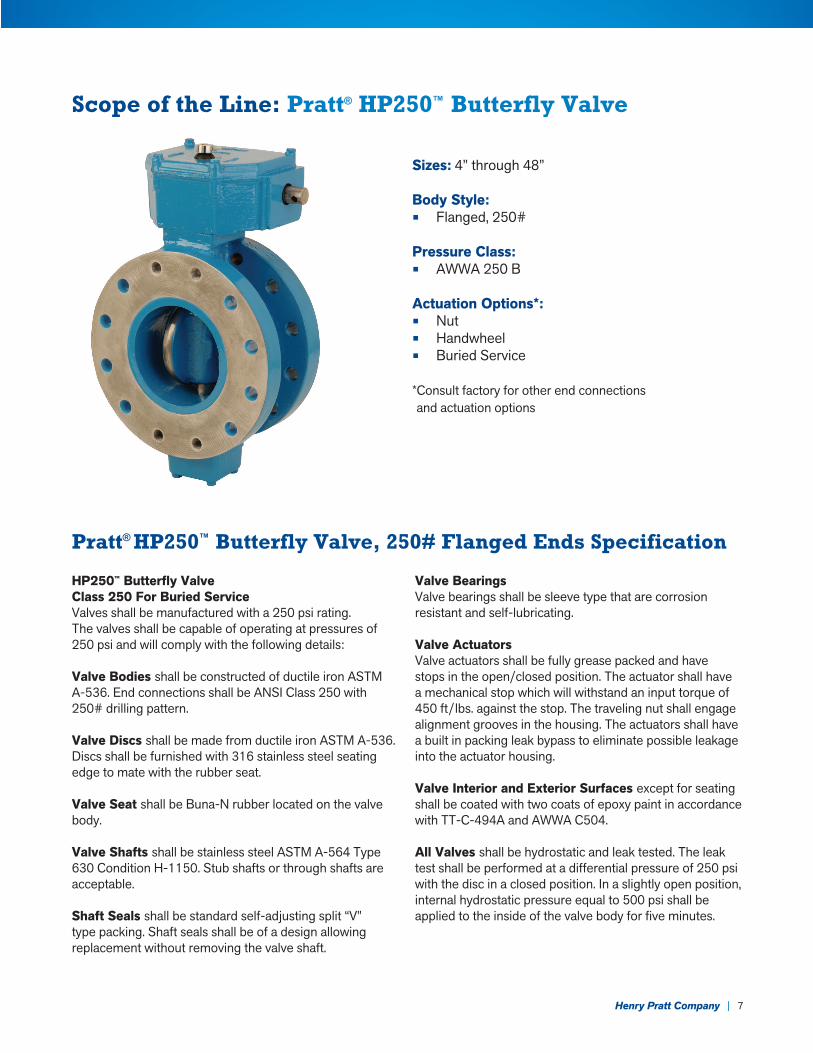
Scope of the Line: Pratt® HP250™ Butterfly Valve
Sizes: 4” through 48”
Body Style:• Flanged, 250#
Pressure Class:• AWWA 250 B Actuation Options*:• Nut• Handwheel• Buried Service
* Consult factory for other end connections and actuation options
HP250™ Butterfly ValveClass 250 For Buried ServiceValves shall be manufactured with a 250 psi rating. The valves shall be capable of operating at pressures of 250 psi and will comply with the following details:
Valve Bodies shall be constructed of ductile iron ASTM A-536. End connections shall be ANSI Class 250 with 250# drilling pattern.
Valve Discs shall be made from ductile iron ASTM A-536. Discs shall be furnished with 316 stainless steel seating edge to mate with the rubber seat.
Valve Seat shall be Buna-N rubber located on the valve body.
Valve Shafts shall be stainless steel ASTM A-564 Type 630 Condition H-1150. Stub shafts or through shafts are acceptable.
Shaft Seals shall be standard self-adjusting split “V” type packing. Shaft seals shall be of a design allowing replacement without removing the valve shaft.
Valve BearingsValve bearings shall be sleeve type that are corrosion resistant and self-lubricating.
Valve ActuatorsValve actuators shall be fully grease packed and have stops in the open/closed position. The actuator shall have a mechanical stop which will withstand an input torque of 450 ft/lbs. against the stop. The traveling nut shall engage alignment grooves in the housing. The actuators shall have a built in packing leak bypass to eliminate possible leakage into the actuator housing.
Valve Interior and Exterior Surfaces except for seating shall be coated with two coats of epoxy paint in accordance with TT-C-494A and AWWA C504.
All Valves shall be hydrostatic and leak tested. The leak test shall be performed at a differential pressure of 250 psi with the disc in a closed position. In a slightly open position, internal hydrostatic pressure equal to 500 psi shall be applied to the inside of the valve body for five minutes.
Pratt® HP250™ Butterfly Valve, 250# Flanged Ends Specification
Henry Pratt Company | 7
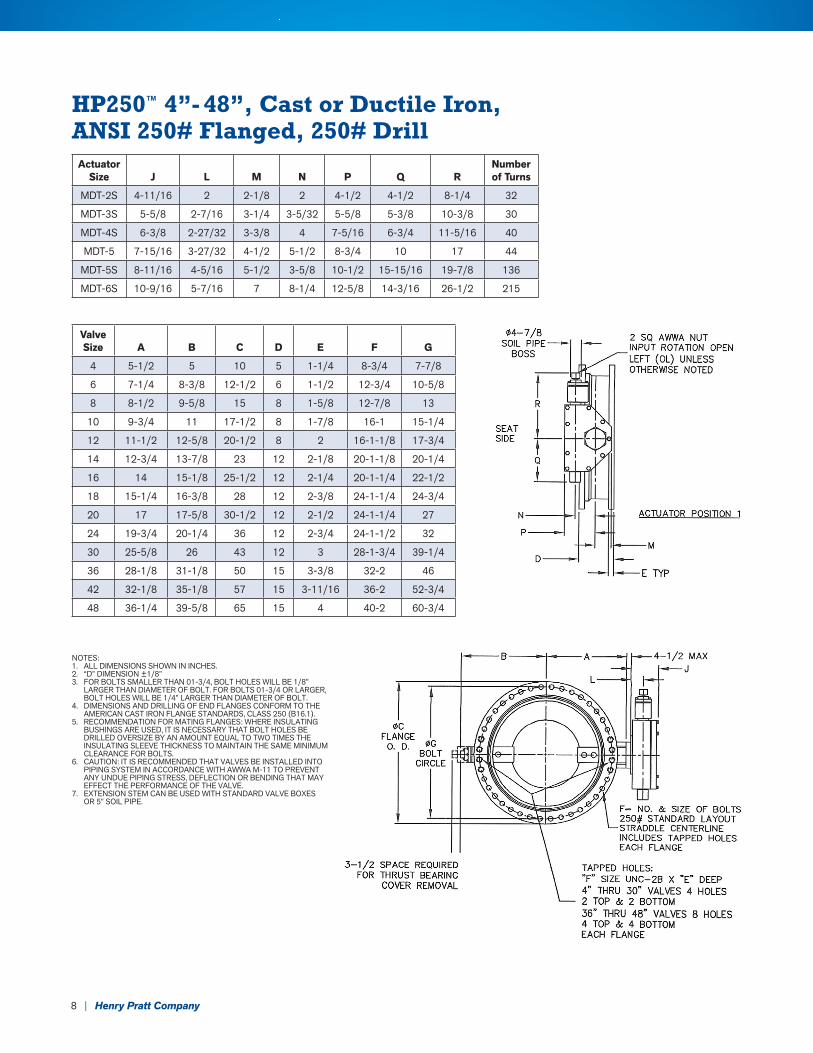
HP250™ 4”- 48”, Cast or Ductile Iron, ANSI 250# Flanged, 250# Drill
NOTES:1. ALL DIMENSIONS SHOWN IN INCHES.2. “D” DIMENSION ±1/8”3. FOR BOLTS SMALLER THAN 01-3/4, BOLT HOLES WILL BE 1/8”
LARGER THAN DIAMETER OF BOLT. FOR BOLTS 01-3/4 OR LARGER, BOLT HOLES WILL BE 1/4” LARGER THAN DIAMETER OF BOLT.
4. DIMENSIONS AND DRILLING OF END FLANGES CONFORM TO THE AMERICAN CAST IRON FLANGE STANDARDS, CLASS 250 (B16.1).
5. RECOMMENDATION FOR MATING FLANGES: WHERE INSULATING BUSHINGS ARE USED, IT IS NECESSARY THAT BOLT HOLES BE DRILLED OVERSIZE BY AN AMOUNT EQUAL TO TWO TIMES THE INSULATING SLEEVE THICKNESS TO MAINTAIN THE SAME MINIMUM CLEARANCE FOR BOLTS.
6. CAUTION: IT IS RECOMMENDED THAT VALVES BE INSTALLED INTO PIPING SYSTEM IN ACCORDANCE WITH AWWA M-11 TO PREVENT ANY UNDUE PIPING STRESS, DEFLECTION OR BENDING THAT MAY EFFECT THE PERFORMANCE OF THE VALVE.
7. EXTENSION STEM CAN BE USED WITH STANDARD VALVE BOXES OR 5” SOIL PIPE.
Actuator Size J L M N P Q R
Number of Turns
MDT-2S 4-11/16 2 2-1/8 2 4-1/2 4-1/2 8-1/4 32
MDT-3S 5-5/8 2-7/16 3-1/4 3-5/32 5-5/8 5-3/8 10-3/8 30
MDT-4S 6-3/8 2-27/32 3-3/8 4 7-5/16 6-3/4 11-5/16 40
MDT-5 7-15/16 3-27/32 4-1/2 5-1/2 8-3/4 10 17 44
MDT-5S 8-11/16 4-5/16 5-1/2 3-5/8 10-1/2 15-15/16 19-7/8 136
MDT-6S 10-9/16 5-7/16 7 8-1/4 12-5/8 14-3/16 26-1/2 215
Valve Size A B C D E F G
4 5-1/2 5 10 5 1-1/4 8-3/4 7-7/8
6 7-1/4 8-3/8 12-1/2 6 1-1/2 12-3/4 10-5/8
8 8-1/2 9-5/8 15 8 1-5/8 12-7/8 13
10 9-3/4 11 17-1/2 8 1-7/8 16-1 15-1/4
12 11-1/2 12-5/8 20-1/2 8 2 16-1-1/8 17-3/4
14 12-3/4 13-7/8 23 12 2-1/8 20-1-1/8 20-1/4
16 14 15-1/8 25-1/2 12 2-1/4 20-1-1/4 22-1/2
18 15-1/4 16-3/8 28 12 2-3/8 24-1-1/4 24-3/4
20 17 17-5/8 30-1/2 12 2-1/2 24-1-1/4 27
24 19-3/4 20-1/4 36 12 2-3/4 24-1-1/2 32
30 25-5/8 26 43 12 3 28-1-3/4 39-1/4
36 28-1/8 31-1/8 50 15 3-3/8 32-2 46
42 32-1/8 35-1/8 57 15 3-11/16 36-2 52-3/4
48 36-1/4 39-5/8 65 15 4 40-2 60-3/4
8 | Henry Pratt Company

Notes
Henry Pratt Company | 9
2 | Henry Pratt Company ©2017 Henry Pratt Company, LLC. | Printed in the U.S.A. | 13296 1/17
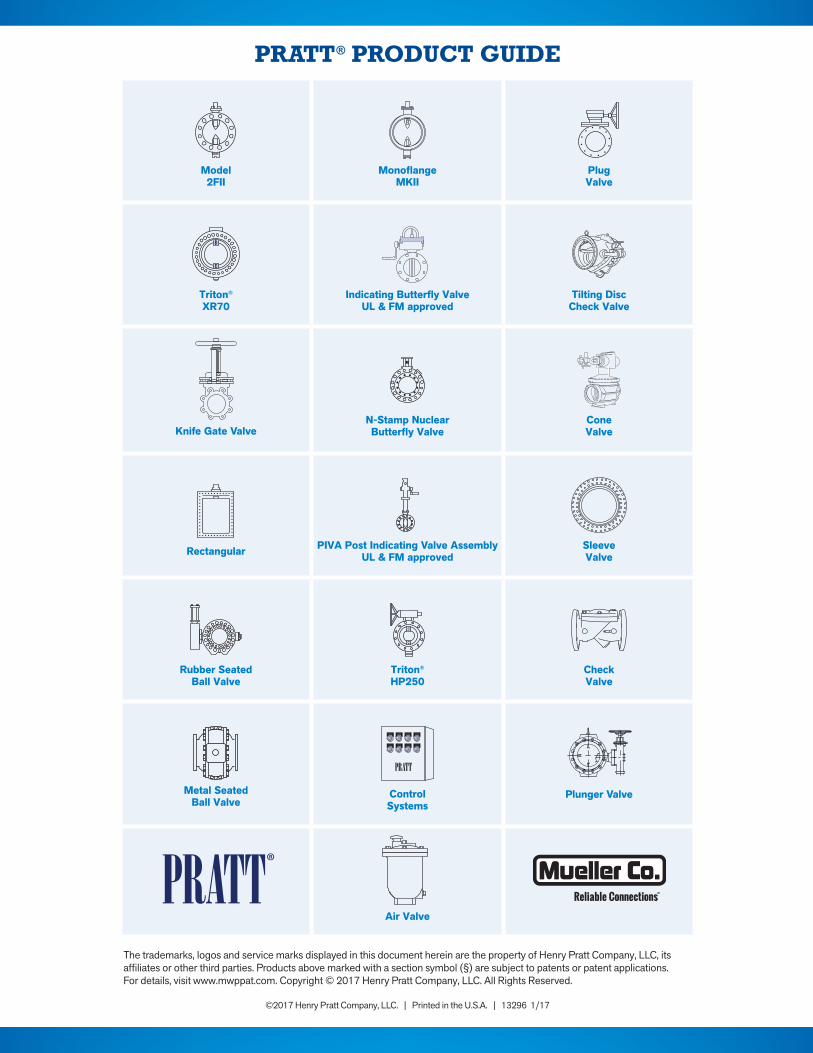
PRATT® PRODUCT GUIDE
Model 2FII
Monoflange MKII
PlugValve
Triton® XR70
Indicating Butterfly ValveUL & FM approved
Tilting Disc Check Valve
Knife Gate ValveN-Stamp Nuclear Butterfly Valve
Cone Valve
Rectangular PIVA Post Indicating Valve AssemblyUL & FM approved
Sleeve Valve
Rubber SeatedBall Valve
Triton® HP250
Check Valve
Metal SeatedBall Valve
ControlSystems
Plunger Valve
Air Valve
The trademarks, logos and service marks displayed in this document herein are the property of Henry Pratt Company, LLC, its affiliates or other third parties. Products above marked with a section symbol (§) are subject to patents or patent applications. For details, visit www.mwppat.com. Copyright © 2017 Henry Pratt Company, LLC. All Rights Reserved.