HP ProLiant DL980 G7 Server - Maintenance and Service Guide 2013-05 v8
112
HP ProLiant DL980 G7 Server Maintenance and Service Guide Abstract This document describes service procedures for the HP ProLiant DL980 G7 Server. This document is intended for experienced service technicians. HP assumes that you are qualified in the servicing of computer equipment, are trained in recognizing hazards in products with hazardous energy levels, and are familiar with weight and stability precautions for rack installations. HP Part Number: AM426-9001H Published: May 2013 Edition: 8
description
HP ProLiant DL980 G7 Server - Maintenance and Service Guide (2013-05 v8)
Transcript of HP ProLiant DL980 G7 Server - Maintenance and Service Guide 2013-05 v8
HP ProLiant DL980 G7 Server Maintenanceand Service Guide
AbstractThis document describes service procedures for the HP ProLiant DL980 G7 Server. This document is intended for experiencedservice technicians. HP assumes that you are qualified in the servicing of computer equipment, are trained in recognizinghazards in products with hazardous energy levels, and are familiar with weight and stability precautions for rack installations.
HP Part Number: AM426-9001HPublished: May 2013Edition: 8

© Copyright 2010, 2013 Hewlett-Packard Development Company, L.P.
Notices
The information contained herein is subject to change without notice. The only warranties for HP products and services are set forth in the expresswarranty statements accompanying such products and services. Nothing herein should be construed as constituting an additional warranty. HP shallnot be liable for technical or editorial errors or omissions contained herein.
Windows® and Windows Server® are U.S. registered trademarks of Microsoft Corporation. Intel® and Xeon® are trademarks of Intel Corporationin the United States and other countries.

Contents1 Illustrated parts catalog...............................................................................5
Mechanical Components...........................................................................................................5System components...................................................................................................................9
2 Removal and replacement procedures.........................................................21Required tools........................................................................................................................21Safety considerations..............................................................................................................21
Preventing electrostatic discharge.........................................................................................21Server warnings and cautions..............................................................................................21
Power off the server.................................................................................................................22SAS hard drive blank..............................................................................................................22SAS/SATA hard drive..............................................................................................................22DVD-ROM drive......................................................................................................................23Power supply blank.................................................................................................................23Hot-plug power supply............................................................................................................24Fans.....................................................................................................................................25
Upper fans........................................................................................................................25Lower fan module..............................................................................................................25
Remove the upper or lower processor memory drawer or processor memory drawer blank...............26Remove a processor memory drawer cover................................................................................27Memory cartridge...................................................................................................................27DIMMs..................................................................................................................................30
Memory options................................................................................................................32DIMM support...................................................................................................................34Single-, dual-, and quad-rank DIMMs...................................................................................34DIMM identification...........................................................................................................35DIMM installation guidelines...............................................................................................35Memory cartridge population guidelines...............................................................................36Memory subsystem architecture............................................................................................36Hemisphere mode..............................................................................................................37Memory performance optimization.......................................................................................38Memory RAS.....................................................................................................................38Advanced ECC memory population guidelines......................................................................39Online Spare memory population guidelines.........................................................................39Mirrored Memory population guidelines...............................................................................40
Heatsink................................................................................................................................42Processor...............................................................................................................................44Expansion slot cover...............................................................................................................49Low profile I/O expander........................................................................................................50Non-hot-plug expansion board.................................................................................................52Battery-backed write cache procedures......................................................................................53
Removing the BBWC cache module......................................................................................53Removing the BBWC battery pack........................................................................................54BBWC low profile I/O expander location.............................................................................55Recovering data from the battery-backed write cache..............................................................55
Remove the SPI board.............................................................................................................56Systems Insight Display assembly..............................................................................................57Front bezel.............................................................................................................................58Solid state drive......................................................................................................................59Battery..................................................................................................................................60I/O expansion board..............................................................................................................61
Expansion board options....................................................................................................63
Contents 3

SAS backplane......................................................................................................................67XNC module..........................................................................................................................67System board.........................................................................................................................68
Re-entering the server serial number and product ID...............................................................70Power backplane....................................................................................................................70HP Trusted Platform Module.....................................................................................................72
3 Upgrading a 4s configuration to an 8s configuration....................................744 Flashing firmware.....................................................................................75
Flashing firmware requirements.................................................................................................75Flashing firmware using Offline Update.....................................................................................76Flashing firmware using Smart Components...............................................................................77
Procedure for Windows and Linux operating systems..............................................................77Procedure for Solaris and VMware operating systems.............................................................82
5 Component identification...........................................................................83Front panel components...........................................................................................................83Front panel LEDs.....................................................................................................................84System Insight Display LEDs......................................................................................................85
Processor and memory board configuration / logical (physical) location...................................87Hard drive LEDs.....................................................................................................................87Hard drive LED combinations...................................................................................................87Rear panel components...........................................................................................................88Rear panel LEDs.....................................................................................................................90Power supply LED...................................................................................................................91Fan location...........................................................................................................................92System board components.......................................................................................................94
System maintenance switch.................................................................................................95SPI board components.............................................................................................................96Expansion board components..................................................................................................96DIMM slot locations................................................................................................................98Device numbers......................................................................................................................99Battery pack LEDs...................................................................................................................99
6 Cabling................................................................................................102XNC cabling.......................................................................................................................102DVD-ROM drive cabling........................................................................................................103
7 Specifications.........................................................................................104Environmental Specifications..................................................................................................104Server Specifications.............................................................................................................105
8 Acronyms and abbreviations....................................................................1079 Documentation feedback.........................................................................109Index.......................................................................................................110
4 Contents

1 Illustrated parts catalogMechanical Components
NOTE: The list of part numbers is current and correct as of the publication of the document. Partnumbers change often. Check the HP Partsurfer website (http://partsurfer.hp.com/search.aspx),to ensure you have the latest part numbers associated with this product.
Customer self repairSpare part numberDescriptionItem
Mandatory1AM426-69016Access panel1
Mandatory1AM426-69002Processor memory drawertop
2
Mandatory1AM426-69019Bezel - Upperprocessor-memory drawer,frontal access
—
Mandatory1392613-001Blank, hard drive3
Mandatory1591209-001Bezel assembly, power, SID4
Mandatory1AM426-69021Bezel - Frontal section ofprocessor-memory drawer
5
Mandatory1AM426-69018Processor memory drawerbottom
6
Mandatory1AM426-69008Blank, lower processormemory drawer
Not shown
Mechanical Components 5

Customer self repairSpare part numberDescriptionItem
Mandatory1AM426-69020Bezel - Lowerprocessor-memory drawer,frontal access
—
Mandatory1199630-001Tool, T-15 Torx screwdriver7
Mandatory1496058-001Blank, power supply8
Mandatory1AM426-69014Plastics KitNot shown
Mandatory1496058-001Hardware kit - contains aheatsink blank, optical
Not shown
device blank, fan blank,full-length expansion slotcover, low-profile expansionslot cover, PCI retainer, PCItop retainer, PCI endretainer, and PCI removableretainer
Mandatory1AM426-69022Bezel kit - Miscellaneousparts included
Not shown
Mandatory1AM426-2104A3-8 U Slide rail kitNot shown
1 Mandatory—Parts for which customer self repair is mandatory. If you request HP to replace theseparts, you will be charged for the travel and labor costs of this service.2 Optional—Parts for which customer self repair is optional. These parts are also designed forcustomer self repair. If, however, you require that HP replace them for you, there may or may notbe additional charges, depending on the type of warranty service designated for your product.3 No—Some HP parts are not designed for customer self repair. In order to satisfy the customerwarranty, HP requires that an authorized service provider replace the part. These parts are identifiedas "No" in the Illustrated Parts Catalog.—1 Mandatory: Obligatoire—Pièces pour lesquelles la réparation par le client est obligatoire. Sivous demandez à HP de remplacer ces pièces, les coûts de déplacement et main d'oeuvre duservice vous seront facturés.2 Optional: Facultatif—Pièces pour lesquelles la réparation par le client est facultative. Ces piècessont également conçues pour permettre au client d'effectuer lui-même la réparation. Toutefois, sivous demandez à HP de remplacer ces pièces, l'intervention peut ou non vous être facturée, selonle type de garantie applicable à votre produit.3No: Non—Certaines pièces HP ne sont pas conçues pour permettre au client d'effectuer lui-mêmela réparation. Pour que la garantie puisse s'appliquer, HP exige que le remplacement de la piècesoit effectué par un Mainteneur Agréé. Ces pièces sont identifiées par la mention “Non” dans leCatalogue illustré.—1 Mandatory: Obbligatorie—Parti che devono essere necessariamente riparate dal cliente. Se ilcliente ne affida la riparazione ad HP, deve sostenere le spese di spedizione e di manodoperaper il servizio.2Optional: Opzionali—Parti la cui riparazione da parte del cliente è facoltativa. Si tratta comunquedi componenti progettati per questo scopo. Se tuttavia il cliente ne richiede la sostituzione ad HP,potrebbe dover sostenere spese addizionali a seconda del tipo di garanzia previsto per il prodotto.
6 Illustrated parts catalog

3No: Non CSR—Alcuni componenti HP non sono progettati per la riparazione da parte del cliente.Per rispettare la garanzia, HP richiede che queste parti siano sostituite da un centro di assistenzaautorizzato. Tali parti sono identificate da un “No” nel Catalogo illustrato dei componenti.—1Mandatory: Zwingend—Teile, die im Rahmen des Customer Self Repair Programms ersetzt werdenmüssen. Wenn Sie diese Teile von HP ersetzen lassen, werden Ihnen die Versand- und Arbeitskostenfür diesen Service berechnet.2 Optional: Optional—Teile, für die das Customer Self Repair-Verfahren optional ist. Diese Teilesind auch für Customer Self Repair ausgelegt. Wenn Sie jedoch den Austausch dieser Teile vonHP vornehmen lassen möchten, können bei diesem Service je nach den für Ihr Produkt vorgesehenenGarantiebedingungen zusätzliche Kosten anfallen.3 No: Kein—Einige Teile sind nicht für Customer Self Repair ausgelegt. Um den Garantieanspruchdes Kunden zu erfüllen, muss das Teil von einem HP Servicepartner ersetzt werden. Im illustriertenTeilekatalog sind diese Teile mit „No“ bzw. „Nein“ gekennzeichnet.—1 Mandatory: Obligatorio—componentes para los que la reparación por parte del usuario esobligatoria. Si solicita a HP que realice la sustitución de estos componentes, tendrá que hacersecargo de los gastos de desplazamiento y de mano de obra de dicho servicio.2Optional: Opcional— componentes para los que la reparación por parte del usuario es opcional.Estos componentes también están diseñados para que puedan ser reparados por el usuario. Sinembargo, si precisa que HP realice su sustitución, puede o no conllevar costes adicionales,dependiendo del tipo de servicio de garantía correspondiente alproducto.3 No: No—Algunos componentes no están diseñados para que puedan ser reparados por elusuario. Para que el usuario haga valer su garantía, HP pone como condición que un proveedorde servicios autorizado realice la sustitución de estos componentes. Dichos componentes seidentifican con la palabra “No” en el catálogo ilustrado de componentes.—1Mandatory: Verplicht—Onderdelen waarvoor Customer Self Repair verplicht is. Als u HP verzoektdeze onderdelen te vervangen, komen de reiskosten en het arbeidsloon voor uw rekening.2 Optional: Optioneel—Onderdelen waarvoor reparatie door de klant optioneel is. Ook dezeonderdelen zijn ontworpen voor reparatie door de klant. Als u echter HP verzoekt deze onderdelenvoor u te vervangen, kunnen daarvoor extra kosten in rekening worden gebracht, afhankelijk vanhet type garantieservice voor het product.3 No: Nee—Sommige HP onderdelen zijn niet ontwikkeld voor reparatie door de klant. In verbandmet de garantievoorwaarden moet het onderdeel door een geautoriseerde Service Partner wordenvervangen. Deze onderdelen worden in de geïllustreerde onderdelencatalogus aangemerkt met"Nee".—1 Mandatory: Obrigatória—Peças cujo reparo feito pelo cliente é obrigatório. Se desejar que aHP substitua essas peças, serão cobradas as despesas de transporte e mão-de-obra do serviço.2 Optional: Opcional—Peças cujo reparo feito pelo cliente é opcional. Essas peças também sãoprojetadas para o reparo feito pelo cliente. No entanto, se desejar que a HP as substitua, podehaver ou não a cobrança de taxa adicional, dependendo do tipo de serviço de garantia destinadoao produto.3 No: Nenhuma—Algumas peças da HP não são projetadas para o reparo feito pelo cliente. Afim de cumprir a garantia do cliente, a HP exige que um técnico autorizado substitua a peça.Essas peças estão identificadas com a marca “No” (Não), no catálogo de peças ilustrado.
Mechanical Components 7

8 Illustrated parts catalog

System components
NOTE: The list of part numbers is current and correct as of the publication of the document. Partnumbers change often. Check the HP Partsurfer website (http://partsurfer.hp.com/search.aspx),to ensure you have the latest part numbers associated with this product.
Customer self repairSpare part numberDescriptionItem
Mandatory1591204-001588139-B21
PCI-X/PCI Express I/Oexpansion board
1
Mandatory1591205-001588137-B21
PCI Express I/O expansionboard
2
Optional2AM426-69015System board3
——SPI board4
Mandatory1AM426-69017HP ProLiant DL980 NC375iSPI Board
—
Mandatory1AM451-69002HP ProLiant DL980 331i SPIBoard
—
Optional2591198-001Memory module5
Optional2591207-001Heatsink assembly6
——Memory7
System components 9

Customer self repairSpare part numberDescriptionItem
Mandatory1501533-0012 GB (128 MBx8), 133PC3-10600R, DDR3 DIMMmemory module
—
Mandatory1501534-0014 GB (256MBx4), 133MHz, PC3-10600R, DDR3DIMMmemory module1Rx4
—
Mandatory1595424-0014 GB, PC3-10600R,DDR3-1333, single-rankmemory module
—
Mandatory1606426-0014 GB PC3L 10600RDDR3-1333 memory module
—
Mandatory1501536-0018 GBPC3-10600R-DDR3-133MHz RDIMM
—
Mandatory1606427-0018GB PC3L 10600RDDR3-1333 memory module
—
Mandatory1501538-00116 GB DDR3-106,PC3-8500R memory module(512 MBx4)
—
Mandatory1632204-00116GB (1x16GB) memoryDIMM - Dual rank x4,
—
PC3L-10600, DDR3-1333,Registered CAS-9 LP
Mandatory1632205-00132GB memory DIMM 32GB4RX4 PC3L-8500R-9A
—
——Processors8
Mandatory1597821-001Intel Xeon e7520 4 coreprocessor, 1.86 GHz [1 GB
—
Level-2 cache (256 KB percore), LGA 1567 socket, 95W TDP]
Mandatory1594899-001Intel Xeon E6540 6 coreprocessor, 2.00 GHz [1.5
—
GB Level-2 cache (256 KBper core), LGA 1567 socket,105 W TDP]
Mandatory1594896-001Intel Xeon X6550 8 coreprocessor, 2.00 GHz [2 GB
—
Level-2 cache (256 KB percore), LGA 1567 socket,130 W TDP]
Mandatory1594893-001Intel Xeon X7500 8 coreprocessor, 2.27 GHz [2 GB
—
Level-2 cache (256 KB percore), LGA 1567 socket,130W TDP]
Mandatory1653055-001HP DL980 6 Core E7-48071.86 processor kit
—
Mandatory1650016-001HP DL980 10 Core E7-28502.0 processor kit
—
Mandatory1650017-001Intel Xeon E7-28304-processor kit, 2.13GHz
—
10 Illustrated parts catalog

Customer self repairSpare part numberDescriptionItem
(24MB Level-2 cache,6.40GT/s)
Mandatory1650015-001HP DL980 10 Core E7-28602.26 processor kit
—
Mandatory1653050-001HP DL980 10 Core E7-48702.4 processor kit
—
Optional2395532-001Thermal grease kitNot shown
No3AM426-69001Power backplane9
——Memory cartridge11
Optional2591198-001Memory cartridge for IntelXeon 7500/6500 Seriesprocessor
—
Optional2647058-001Memory cartridge for IntelXeon E7 Family processor:HP DL980
—
Optional2591203-001SAS backplane13
Optional2AM426-69003Systems Insight Displayassembly
14
——SFF hot-plug drives (notshown)
15
Mandatory1512743-001B21a) 72-GB, 6G SAS,15,000-rpm, 6.35-cm(2.5-in)
—
Mandatory1512744-001b) 146-GB, 6G SAS,15,000-rpm, 6.35-cm(2.5-in)
—
Mandatory1507284-001c) 300 GB, 6G SAS,10,000-rpm 6.35-cm:DL980 (2.5-in)
—
Mandatory1581284-B21d) 450 GB, 6G SAS,10,000 rpm 6.35 cm (2.5in)
—
Mandatory1581286-B21e) 600 GB, 6G SAS,10,000 rpm 6.35 cm (2.5in)
—
Mandatory1619291-B21f) 900 GB, 6G SAS, 10,000rpm 6.35 cm (2.5 in)
—
Mandatory1507127-B21HP 300 GB SAS 10K SFF(2.5 in.) dual port enterprisehard drive
—
Mandatory1512545-B21HP 72 GB SAS 15K SFF(2.5 in.) dual port enterprisehard drive
—
Mandatory1512547-B21HP 146 GB SAS 15K SFF(2.5 in.) dual port enterprisehard drive
—
——Solid state drivesNot shown
System components 11

Customer self repairSpare part numberDescriptionItem
Mandatory1572071-B21a) 60 GB 3G SATA, 6.35cm (2.5 in), MDL SSD
—
Mandatory1572073-B21b) 120 GB, 3G SATA, 6.35cm (2.5 in) MDL SSD
—
Mandatory1632492-B21c) 200 GB, SAS, 6.35 cm(2.5 in) SSD SLC drive
—
Mandatory1632494-B21e) 400 GB, SAS, 6.35 cm(2.5 in) SSD SLC drive
—
——Media drivesNot shown
Mandatory1481428-001481041-B21
a) SATA DVD-ROM drive—
Mandatory1481429-001481043-B21
b) SATA DVD RW drive—
Mandatory1AM426-69013Fan, lower module16
Mandatory1AM426-69012Small form factor PCIExpress I/O expansionmodule
17
Mandatory1AM426-69009XNC module18
Mandatory1579229-001Power supply PHB - 1200W,12V, 1U form factor,
19
hot-pluggable, redundant,high-efficiency
Mandatory1578322-B21HP 1200W CS PlatinumPower Supply Kit
Not shown
——I/ONot shown
Mandatory1593120-001SCSI U320e host busadapter (HBA), dual
—
channel, PCIe, with lowvoltage differential (LVD)
Mandatory1593412-001Host channel adapter - IB 4xquad data rate (QDR) CX-2
—
PCIe dual port host channeladapter
Mandatory1488765-B21HP SC08Ge HBA—
Mandatory1503746-B21HP NC112T PCIe GigabitServer Adapter
—
Mandatory1412648-B21HP NC360T PCIe Dual Port1Gb Server Adapter
—
Mandatory1593722-B21HP NC365T 4-port EthernetServer Adapter
—
Mandatory1394793-B21HP NC373F PCIe Mfn 1GbEServer Adapter
—
Mandatory1394791-B21HP NC373T PCIe Mfn 1GbEServer Adapter
—
Mandatory1538696-B21HP NC375T PCIe 4PrtGigabit Server Adapter
—
12 Illustrated parts catalog

Customer self repairSpare part numberDescriptionItem
Mandatory1458492-B21HP NC382T PCIe Dual-PortMultifunction Gb ServerAdapter
—
Mandatory1593717-B21HP NC523SFP 10Gb 2PAdapter
—
Mandatory1489892-B21HP NC524SFP Dual Port10GbE Module
—
Mandatory1581201-B21HP NC550SFP 2 -port PCIex8 Ethernet Adapter
—
Mandatory1458491-001HP NC382T PCIe Dual PortMultifunction Gigabit ServerAdapter
—
Mandatory1462594-001SAS controller board, for usein the Smart Array P212controller
—
Mandatory1462834-B21HP P212/256 Smart Arraycontroller
—
Mandatory1462830-B21HP P411/256 Smart Arraycontroller
—
Mandatory1462918-001SAS controller board, forSmart Array P411 controller
—
with 256 MB memorymodule
Mandatory1572531-B21HP Smart Array P411controller w/1GB FBWCcontroller
—
Mandatory1578229-B21HP Smart Array P411controller w/512MB FBWCcontroller
—
Mandatory1487204-B21HP Smart Array P812/1controller Gb flash, 8-ports
—
internal, 16-ports external,PCIe x8
Mandatory1614988-B21HP SC08e 6 Gb SAS HBA—
Mandatory1587224-001HP Smart Array P812controller, 24 ports, 1 Gb,
—
PCIe, SAS, supports up to108 hard drives
Mandatory1435129-B21HP Smart Array E500/256external controller
—
Mandatory1405132-B21HP Smart Array P400/256SAS controller, PCIe RAID
—
controller with eight internalSerial Attached SCSI portsin a low-profile form factor,supports up to 512MBBBWC and RAID Level-6(ADG)
Mandatory1411064-B21HP Smart Array P400/512rmkt controller
—
System components 13

Customer self repairSpare part numberDescriptionItem
Mandatory1383280-B21HP Smart Array cachebattery kit - For Smart ArrayP400 controller only
—
Mandatory1381513-B21HP Smart Array P800controller
—
Mandatory1462860-B21HP P410/Zero Memory FIOSmart Array controller
—
Mandatory1462862-B21HP Smart Array P410/256controller
—
Mandatory1462864-B21HP Smart Array P400/512rmkt controller
—
Mandatory1491195-B21HP Smart Array P410/256MB BBWC controller
—
Mandatory1572532-B21HP Smart Array P410 with1GB FBWC controller
—
Mandatory1578230-B21HP P410 with 512MBFBWC controller
—
Mandatory1468406-B21HP SAS Expander Card—
Mandatory1AK344AHP StorageWorks 81QPCI-e FC HBA
—
Mandatory1AE312AHP StorageWorks FC1242SR 4Gb PCIe dualchannel HBA
—
Mandatory1A8003AHP StorageWorks FC2242SR 4Gb PCIe dualchannel HBA
—
Mandatory1AE311AHP StorageWorks FC1142SR 4Gb PCIe HBA
—
Mandatory1A8002AHP StorageWorks FC2142SR 4Gb PCIe HBA
—
Mandatory1AJ763AHP StorageWorks 82E 8GbDual-port PCIe FC HBA
—
Mandatory1AJ764AHP StorageWorks 82Q 8GbDual Port PCI-e FC HBA
—
Mandatory1AJ762AHP StorageWorks 81E 8GbSP PCI-e FC HBA
—
Mandatory1468508-001HP StorageWorks 8 Gbshort wave FC SFFtransceiver
—
Mandatory1AP768AHP StorageWorks 42B PCIe4Gb Dual Port
—
Mandatory1AP767AHP StorageWorks 41B PCIe4Gb Single Port
—
Mandatory1AP770AHP StorageWorks 82B PCIe8Gb Dual Port
—
Mandatory1AP769AHP StorageWorks 81B PCIe8Gb Single Port
—
14 Illustrated parts catalog
Customer self repairSpare part numberDescriptionItem
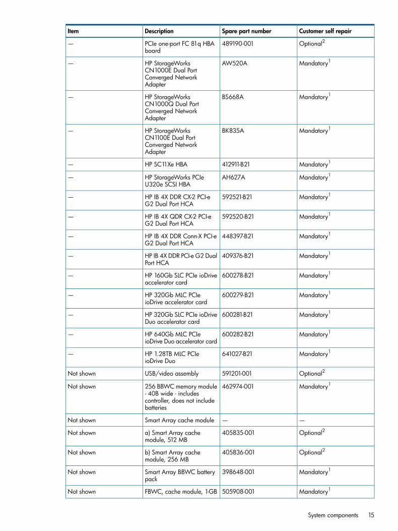
Optional2489190-001PCIe one-port FC 81q HBAboard
—
Mandatory1AW520AHP StorageWorksCN1000E Dual Port
—
Converged NetworkAdapter
Mandatory1BS668AHP StorageWorksCN1000Q Dual Port
—
Converged NetworkAdapter
Mandatory1BK835AHP StorageWorksCN1100E Dual Port
—
Converged NetworkAdapter
Mandatory1412911-B21HP SC11Xe HBA—
Mandatory1AH627AHP StorageWorks PCIeU320e SCSI HBA
—
Mandatory1592521-B21HP IB 4X DDR CX-2 PCI-eG2 Dual Port HCA
—
Mandatory1592520-B21HP IB 4X QDR CX-2 PCI-eG2 Dual Port HCA
—
Mandatory1448397-B21HP IB 4X DDR Conn-X PCI-eG2 Dual Port HCA
—
Mandatory1409376-B21HP IB 4X DDR PCI-e G2 DualPort HCA
—
Mandatory1600278-B21HP 160Gb SLC PCIe ioDriveaccelerator card
—
Mandatory1600279-B21HP 320Gb MLC PCIeioDrive accelerator card
—
Mandatory1600281-B21HP 320Gb SLC PCIe ioDriveDuo accelerator card
—
Mandatory1600282-B21HP 640Gb MLC PCIeioDrive Duo accelerator card
—
Mandatory1641027-B21HP 1.28TB MLC PCIeioDrive Duo
—
Optional2591201-001USB/video assemblyNot shown
Mandatory1462974-001256 BBWC memory module- 40B wide - includes
Not shown
controller, does not includebatteries
——Smart Array cache moduleNot shown
Optional2405835-001a) Smart Array cachemodule, 512 MB
Not shown
Optional2405836-001b) Smart Array cachemodule, 256 MB
Not shown
Mandatory1398648-001Smart Array BBWC batterypack
Not shown
Mandatory1505908-001FBWC, cache module, 1-GBNot shown
System components 15

Customer self repairSpare part numberDescriptionItem
Mandatory1534915-B21HP 512 MB FBWC moduleNot shown
Mandatory1534562-B21HP 1 GB FBWC moduleNot shown
Mandatory1578882-001FBWC module, 512 MBNot shown
Mandatory1587324-001FBWC capacitor packNot shown
Optional2490712-001NC524SFP dual-port 10GBEmodule
Not shown
Optional2587225-001Super capacitor moduleNot shown
Mandatory1436431-001PCIe mezzanine NIC card -4-port, 1000base-T fiberconnector (FC)
—
Mandatory1489103-0018-port external SAS HBAboard
—
Mandatory1489191-001PCIe dual-port FC 82q HBAboard
—
Mandatory1489192-001PC board - PCIe single -portFC 81e HBA board
—
Mandatory1489193-001PC board - PCIe dual-port FC82e HBA board
—
Mandatory1397739-0014Gb PCIe to FC HBA -StorageWorks FC142SRsingle-channel
—
Mandatory1397740-0014Gb PCIe to FC HBA -StorageWorks FC2242SRdual-port
—
Mandatory1407620-0014 GB PCIe to FC HBA(QLogic) Features one
—
4Gbps FC port with SFFmultimode optic with LC-styleconnector, automatic speednegotiation, and MPIO
Mandatory1407621-001PCIe dual FC HBA (QLogic)-4GB, optical LC type
—
connector, automatic speednegotiation, MPIO basic
Mandatory1412651-001Intel NC360T PCIe 2-portGb (1000 Base-T) server
—
NIC adapter - includes astandard-height bracketattached
Mandatory1468332-B21HP NC522SFP Dual-Port10GbE Gigabit ServerAdapter
—
Mandatory1397740-0014Gb PCIe-to-FC HBA -StorageWorks FC2242SRdual-channel
—
Mandatory1397740-0014Gb PCIe-to-FC HBA -StorageWorks FC2242SRdual-channel
—
Mandatory1445009-001SCSI U320e (HBA) - dualchannel, PCIe, with LVD
—
16 Illustrated parts catalog

Customer self repairSpare part numberDescriptionItem
Mandatory1445009-002Dual-channel Ultra320 PCIEHBA
—
Mandatory1466515-001PC board - HBA, 81Q, FC,PCIe
—
Mandatory1468349-001SPS-BD,NC522SFP+ 10gigabit,SE
—
Mandatory1489190-001PCIe one-port FC 81q HBAboard
—
Mandatory1503827-001SPS-BD,NC112T,PCIegigabit ADP
—
Mandatory1539931-001SPS-BD NIC PXIE 4P10/100/1000
—
Mandatory1581201-B21HP NC550SFP 10Gb 2-portPCIe x8 Ethernet Adapter
—
Mandatory1586444-001NC550SFP dual-port 10GbEserver adapter
—
Mandatory1593413-001SPS-BD mezzanine 4X DDRIB CX G2 dual-port
—
Mandatory1593743-001Quad port NC365T adapter- 1 gigabit Ethernet (GbE)
—
Mandatory1600474-001PC board - ioDriveaccelerator card, 160 GB,
—
logical Not And (NAND)flash, Single Level Cell (SLC),bandwidth (64kB) 750MBswrites, 770MBs reads,access latency (512 Byte)twenty-six microseconds,123,000 InterfaceOperating Procedures (IOPS)75/25 R/W
Mandatory1600475-001PC board - ioDriveaccelerator card, 320GB,
—
logical NAND flash, MLC,bandwidth (64kB) 510MBswrites, 735M/s reads,access latency (512 Byte)twenty-nine microseconds,67000 IOPS (75/25 R/W)
Mandatory1600477-001PC board - ioDriveaccelerator card, 320GB,
—
logical NAND flash, SLC,bandwidth (64kB) 1.5GBswrites 1.5GBs reads, accesslatency (512 Byte) twenty-sixmicroseconds, 238,000IOPS 75/25 R/W mix
Mandatory1600478-001PC board - ioDriveaccelerator card, 640GB,
—
logical NAND flash, MLC,bandwidth (64kB) 1.0GBswrites, 1.5GBs reads,access latency (512 byte)twenty-nine microseconds,
System components 17

Customer self repairSpare part numberDescriptionItem
138, 000 IOPS 75/25R/W mix
Mandatory1581135-001SPS-PCA Mini-DIMM 512MBNot shown
Mandatory1153099-001Battery, 3V, LithiumNot shown
Mandatory1AM426-69011Cable kit for DL980G7Not shown
Mandatory1—a) Cable assembly, USB,video
Not shown
Mandatory1—b) Cable assembly, power,UID
Not shown
Mandatory1—c) Cable assembly, SASpower
Not shown
Mandatory1—d) Cable, SATA DVDNot shown
Mandatory1—e) Cable assembly, SSDNot shown
Mandatory1—f) Cable assembly, power,fan, backplane/SPI
Not shown
Mandatory1—g) Cable assembly, thermalsensor
Not shown
Mandatory1—g) Cable assembly, MiniSAS (SPI to SAS backplane)
Not shown
Mandatory1496071-001SATA DVD power cableNot shown
Mandatory1409124-001Cable assembly, 5A BBWCbattery
Not shown
Optional2501025-001Cable assembly, SATApower/data
Not shown
Mandatory1498426-001Cable assembly, mini-SAS,83.8 cm (33-in)
Not shown
Mandatory1531997-001Cable - Serial ATA (SATA),power / data
Not shown
Mandatory1AM426-69023Cable, XNC JLink, 35.56 cm(14 in)
Not shown
No3488069-B21Trusted Platform Module(TPM) kit
Not shown
No3505836-001Trusted Platform Module(TPM)
Not shown
1 Mandatory—Parts for which customer self repair is mandatory. If you request HP to replace theseparts, you will be charged for the travel and labor costs of this service.2 Optional—Parts for which customer self repair is optional. These parts are also designed forcustomer self repair. If, however, you require that HP replace them for you, there may or may notbe additional charges, depending on the type of warranty service designated for your product.3 No—Some HP parts are not designed for customer self repair. In order to satisfy the customerwarranty, HP requires that an authorized service provider replace the part. These parts are identifiedas "No" in the Illustrated Parts Catalog.—
18 Illustrated parts catalog
1 Mandatory: Obligatoire—Pièces pour lesquelles la réparation par le client est obligatoire. Sivous demandez à HP de remplacer ces pièces, les coûts de déplacement et main d'oeuvre duservice vous seront facturés.2 Optional: Facultatif—Pièces pour lesquelles la réparation par le client est facultative. Ces piècessont également conçues pour permettre au client d'effectuer lui-même la réparation. Toutefois, sivous demandez à HP de remplacer ces pièces, l'intervention peut ou non vous être facturée, selonle type de garantie applicable à votre produit.3No: Non—Certaines pièces HP ne sont pas conçues pour permettre au client d'effectuer lui-mêmela réparation. Pour que la garantie puisse s'appliquer, HP exige que le remplacement de la piècesoit effectué par un Mainteneur Agréé. Ces pièces sont identifiées par la mention “Non” dans leCatalogue illustré.—1 Mandatory: Obbligatorie—Parti che devono essere necessariamente riparate dal cliente. Se ilcliente ne affida la riparazione ad HP, deve sostenere le spese di spedizione e di manodoperaper il servizio.2Optional: Opzionali—Parti la cui riparazione da parte del cliente è facoltativa. Si tratta comunquedi componenti progettati per questo scopo. Se tuttavia il cliente ne richiede la sostituzione ad HP,potrebbe dover sostenere spese addizionali a seconda del tipo di garanzia previsto per il prodotto.3No: Non CSR—Alcuni componenti HP non sono progettati per la riparazione da parte del cliente.Per rispettare la garanzia, HP richiede che queste parti siano sostituite da un centro di assistenzaautorizzato. Tali parti sono identificate da un “No” nel Catalogo illustrato dei componenti.—1Mandatory: Zwingend—Teile, die im Rahmen des Customer Self Repair Programms ersetzt werdenmüssen. Wenn Sie diese Teile von HP ersetzen lassen, werden Ihnen die Versand- und Arbeitskostenfür diesen Service berechnet.2 Optional: Optional—Teile, für die das Customer Self Repair-Verfahren optional ist. Diese Teilesind auch für Customer Self Repair ausgelegt. Wenn Sie jedoch den Austausch dieser Teile vonHP vornehmen lassen möchten, können bei diesem Service je nach den für Ihr Produkt vorgesehenenGarantiebedingungen zusätzliche Kosten anfallen.3 No: Kein—Einige Teile sind nicht für Customer Self Repair ausgelegt. Um den Garantieanspruchdes Kunden zu erfüllen, muss das Teil von einem HP Servicepartner ersetzt werden. Im illustriertenTeilekatalog sind diese Teile mit „No“ bzw. „Nein“ gekennzeichnet.—1 Mandatory: Obligatorio—componentes para los que la reparación por parte del usuario esobligatoria. Si solicita a HP que realice la sustitución de estos componentes, tendrá que hacersecargo de los gastos de desplazamiento y de mano de obra de dicho servicio.2Optional: Opcional— componentes para los que la reparación por parte del usuario es opcional.Estos componentes también están diseñados para que puedan ser reparados por el usuario. Sinembargo, si precisa que HP realice su sustitución, puede o no conllevar costes adicionales,dependiendo del tipo de servicio de garantía correspondiente alproducto.3 No: No—Algunos componentes no están diseñados para que puedan ser reparados por elusuario. Para que el usuario haga valer su garantía, HP pone como condición que un proveedorde servicios autorizado realice la sustitución de estos componentes. Dichos componentes seidentifican con la palabra “No” en el catálogo ilustrado de componentes.—1Mandatory: Verplicht—Onderdelen waarvoor Customer Self Repair verplicht is. Als u HP verzoektdeze onderdelen te vervangen, komen de reiskosten en het arbeidsloon voor uw rekening.
System components 19

2 Optional: Optioneel—Onderdelen waarvoor reparatie door de klant optioneel is. Ook dezeonderdelen zijn ontworpen voor reparatie door de klant. Als u echter HP verzoekt deze onderdelenvoor u te vervangen, kunnen daarvoor extra kosten in rekening worden gebracht, afhankelijk vanhet type garantieservice voor het product.3 No: Nee—Sommige HP onderdelen zijn niet ontwikkeld voor reparatie door de klant. In verbandmet de garantievoorwaarden moet het onderdeel door een geautoriseerde Service Partner wordenvervangen. Deze onderdelen worden in de geïllustreerde onderdelencatalogus aangemerkt met"Nee".—1 Mandatory: Obrigatória—Peças cujo reparo feito pelo cliente é obrigatório. Se desejar que aHP substitua essas peças, serão cobradas as despesas de transporte e mão-de-obra do serviço.2 Optional: Opcional—Peças cujo reparo feito pelo cliente é opcional. Essas peças também sãoprojetadas para o reparo feito pelo cliente. No entanto, se desejar que a HP as substitua, podehaver ou não a cobrança de taxa adicional, dependendo do tipo de serviço de garantia destinadoao produto.3 No: Nenhuma—Algumas peças da HP não são projetadas para o reparo feito pelo cliente. Afim de cumprir a garantia do cliente, a HP exige que um técnico autorizado substitua a peça.Essas peças estão identificadas com a marca “No” (Não), no catálogo de peças ilustrado.
20 Illustrated parts catalog

2 Removal and replacement proceduresRequired tools
You need the following items for some procedures:
• Torx T-15 screwdriver (provided with the server)
• Phillips screwdriver
• Flathead screwdriver
• Diagnostics Utility
Safety considerationsBefore performing service procedures, review all the safety information.
Preventing electrostatic dischargeTo prevent damaging the system, be aware of the precautions you need to follow when setting upthe system or handling parts. A discharge of static electricity from a finger or other conductor maydamage system boards or other static-sensitive devices. This type of damage may reduce the lifeexpectancy of the device.To prevent electrostatic damage:
• Avoid hand contact by transporting and storing products in static-safe containers.
• Keep electrostatic-sensitive parts in their containers until they arrive at static-free workstations.
• Place parts on a grounded surface before removing them from their containers.
• Avoid touching pins, leads, or circuitry.
• Always be properly grounded when touching a static-sensitive component or assembly.
Server warnings and cautionsBefore installing a server, be sure that you understand the following warnings and cautions.
WARNING! To reduce the risk of electric shock or damage to the equipment:• Do not disable the power cord grounding plug. The grounding plug is an important safety
feature.• Plug the power cord into a grounded (earthed) electrical outlet that is easily accessible at all
times.• Unplug the power cord from the power supply to disconnect power to the equipment.
• Do not route the power cord where it can be walked on or pinched by items placed againstit. Pay particular attention to the plug, electrical outlet, and the point where the cord extendsfrom the server.
WARNING! To reduce the risk of personal injury from hot surfaces, allow the drives and theinternal system components to cool before touching them.
CAUTION: Do not operate the server for long periods with the access panel open or removed.Operating the server in this manner results in improper airflow and improper cooling that can leadto thermal damage.
Required tools 21

Power off the server
WARNING! To reduce the risk of personal injury, electric shock, or damage to the equipment,disconnect the power cord to remove power from the server. The front panel Power On/Standbybutton does not completely shut off system power. Portions of the power supply and some internalcircuitry remain active until the power cord is disconnected.
NOTE: If installing a hot-plug device, it is not necessary to power down the server.
1. Back up the server data.2. Shut down the operating system as directed by the operating system documentation.3. If the server is installed in a rack, press the UID LED button on the front panel. Blue LEDs
illuminate on the front and rear panels of the server.4. Press the Power On/Standby button to place the server in standby mode. When the server
activates standby power mode, the system power LED changes to amber.5. If the server is installed in a rack, locate the server by identifying the illuminated rear UID LED
button.6. Disconnect the power cords.The system is now without power.
SAS hard drive blank
CAUTION: For proper cooling, do not operate the server without the access panel, baffles,expansion slot covers, or blanks installed. If the server supports hot-plug components, minimize theamount of time the access panel is open.
Remove the component as indicated.
To replace the blank, slide the blank into the bay until it locks into place.
SAS/SATA hard drive
CAUTION: To prevent improper cooling and thermal damage, do not operate the server unlessall bays are populated with either a component or a blank.
To remove the component:1. Determine the status of the drive from the hot-plug SAS hard drive LED combinations (“Hard
drive LED combinations” (page 87)).2. Back up all server data on the hard drive.3. Remove the hard drive.
22 Removal and replacement procedures

To replace the component, reverse the removal procedure.
DVD-ROM driveTo remove the component:1. Power down the server.2. Extend the server from the rack.3. Remove the access panel.4. Disconnect the cable from the rear of the DVD-ROM drive.5. Remove the DVD-ROM drive.
To replace the component, reverse the removal procedure.
Power supply blankRemove the component as indicated.
DVD-ROM drive 23

To replace the component, reverse the removal procedure.
Hot-plug power supplyThe server supports up to eight hot-plug power supplies. Install all power supplies to provide fullredundancy.HP recommends installing redundant hot-plug power supplies in pairs.To confirm the redundancy of your configuration, see the HP power advisor at the HP website(http://www.hp.com/go/hppoweradvisor).
WARNING! To reduce the risk of electric shock or damage to the equipment:• Do not disable the power cord grounding plug. The grounding plug is an important safety
feature.• Plug the power cord into a grounded (earthed) electrical outlet that is easily accessible at all
times.• Unplug the power cord from the power supply to disconnect power to the equipment.
• Do not route the power cord where it can be walked on or pinched by items placed againstit. Pay particular attention to the plug, electrical outlet, and the point where the cord extendsfrom the server.
To remove the component:1. Disconnect the power cord from the failed power supply.2. Remove the failed power supply.
24 Removal and replacement procedures

To replace the component, reverse the removal procedure.
FansNOTE: If two fan fail or if a dual-rotor fan is removed and the "Shutdown" operating systempop-up alert appears, if the hot-plug fans are immediately replaced, the fan sensor state returns to"OK" (Green); however, the 60-second shutdown is not always aborted as it should be, and thesystem continues with its graceful shutdown. This issue occurs because HP Integrated Lights-Out 3(iLO 3) Firmware Version 1.10 detects that when two fans are failed and repaired in quicksuccession, they may be flagged as "Failed" and then "OK" in a random order, so iLO 3 doesnot detect that the shutdown should be canceled when the fans are hot-swapped. A future versionof iLO 3 firmware will prevent the graceful shutdown from continuing if the fans are immediatelyreplaced.There is no workaround to prevent the possible shutdown; however, if the fans fail and need to bereplaced, perform the following instead of hot-swapping the fans:1. Shut down the server and remove the power cord.2. Replace any dual rotor fans (or two individual fans).3. Power the server back on.
Upper fansTo remove the component:1. Extend the server from the rack.2. Remove the access panel.3. Remove the fan.
To replace the component, reverse the removal procedure.
Lower fan moduleTo remove the component:1. Extend the server from the rack.2. Remove the fan module.
Fans 25

To replace the component, reverse the removal procedure.
Remove the upper or lower processor memory drawer or processor memorydrawer blank
1. Power off the server (“Power off the server” (page 22)).2. Release the latches on the release lever.3. Lower the handle, and then extend the processor memory drawer from the server until the
release latches catch.
4. Firmly holding the processor memory drawer, press the release buttons and then remove thedrawer from the server.
The procedure is the same for the upper and lower processor memory drawers, and the processormemory drawer blank.
CAUTION: XNC cabling (“XNC cabling” (page 102)) is required for eight processor systems.Failure to cable the XNC will result in the lower processor memory drawer not being recognizedby the server.
26 Removal and replacement procedures

Remove a processor memory drawer cover1. Power off the server (“Power off the server” (page 22)).2. Remove the processor memory drawer. (“Remove the upper or lower processor memory drawer
or processor memory drawer blank” (page 26))3. Remove the processor memory drawer cover.
The procedure is the same for the upper and lower processor memory drawers, and the processormemory drawer blank.
CAUTION: XNC cabling (“XNC cabling” (page 102)) is required for eight processor systems.Failure to cable the XNC will result in the lower processor memory drawer not being recognizedby the server.
Memory cartridgeNOTE: Be sure you are using the correct spare part number when replacing the memory cartridge.The server ships with one of two different memory cartridges, which are not interchangeable.
To remove the component:1. Power off the server (“Power off the server” (page 22)).2. Remove the processor memory drawer (“Remove the upper or lower processor memory drawer
or processor memory drawer blank” (page 26)).3. Remove the processor memory drawer cover (“Remove a processor memory drawer cover”
(page 27)).4. Remove the failed memory cartridge.
Remove a processor memory drawer cover 27

5. Open the memory cartridge cover.
6. Remove the DIMMs from the failed memory cartridge:a. Open the DIMM slot latches.b. Remove the DIMM.
28 Removal and replacement procedures

To replace the component:1. Install the DIMMs in the replacement memory cartridge:
a. Open the DIMM slot latches.b. Install the DIMM.
2. Close the memory cartridge cover.3. Install the memory cartridge.
Memory cartridge 29

4. Install the processor memory drawer cover.5. Install the processor memory drawer.6. Power up the server.
DIMMsTo remove the component:1. Power down the server.2. Remove the processor memory drawer (“Remove the upper or lower processor memory drawer
or processor memory drawer blank” (page 26)).3. Remove the processor memory drawer cover (“Remove a processor memory drawer cover”
(page 27)).4. Remove the memory cartridge.
5. Open the memory cartridge cover.
30 Removal and replacement procedures

6. Remove the failed DIMM from the memory cartridge:a. Open the DIMM slot latches.b. Remove the DIMM.
To replace the component:1. Install the replacement DIMM in the memory cartridge:
a. Open the DIMM slot latches.b. Install the DIMM.
DIMMs 31

2. Close the memory cartridge cover.3. Install the memory cartridge.
4. Install the processor memory drawer cover.5. Install the processor memory drawer.6. Power up the server.
Memory optionsThis server contains eight memory cartridge connectors in each processor memory drawer. Eachmemory cartridge can contain eight DIMMs, for a total of 128 DIMMs, for a maximum memoryconfiguration of 4 TB.The server supports the following DIMM speeds:
• Single- and dual-rank PC3-10600 (DDR-1333) DIMMs operating at 1066 MHz
• Quad-rank PC3-8500 (DDR-1066) DIMMs operating at 1066 MHz
32 Removal and replacement procedures

Depending on the processor model, the memory clock speed might be reduced to 1066 or 800MHz.
WARNING! There is not enough available PCI memory to allocate to all devices installed in thesystem. Devices which were not allocated requested resources may not operate properly.This occursduring the I/O configuration phase of POST, after the System ROM has allocated most of theavailable memory for some PCI devices, leaving insufficient memory for PCI devices that have notyet been configured.The above message is an indication that the HP ProLiant DL980 G7 serverhas encountered this MMIO limitation and does not indicate an issue with the server. It can occurwhen the I/O configuration of the server demands resources beyond those which the platformarchitecture allows.This message is an indication that the HP ProLiant DL980 G7 server hasencountered this MMIO limitation and does not indicate an issue with the server. It can occur whenthe I/O configuration of the server demands resources beyond those which the platform architectureallows.If some PCI devices are not allocated memory and the warning message appears duringPOST, perform one or more of the following potential workarounds to allow the remaining PCIdevices to receive their requested memory allocations:If the server operating system documentationstates that it requires 2GB (or more) of memory below the 4GB address boundary, do not performStep 1 below because it may result in operating system boot failure.If the operating systemdocumentation does not specify its memory requirements below the 4GB boundary, the Step 1procedure below may be attempted. However, if performing Step 1 results in operating systemboot failure, perform Step 1 again and change Memory Mapped I/O Options to the default valueof 2GB of Memory Mapped I/O , and then perform Step 2 below:1. Change the MMIO Settings in the ROM-Based Setup Utility (RBSU).
a. Boot the server.b. Press the F9 key during POST (when the F9 prompt appears).c. Select Advanced Options.d. Select Advanced System ROM Options.e. Select Memory Mapped I/O Options.f. Change the default selection of 2GB of Memory Mapped I/O to either 3GB of Memory
Mapped I/O or Automatically configure Memory Mapped I/O.g. Reboot the server and verify that no warning messages appear during POST. If the
operating system will not boot, perform Step 1 again and reset Memory Mapped I/OOptions to the default value of 2GB of Memory Mapped I/O .
2. If the warning message continues to appear, ensure that all slotted PCI devices are usingupdated firmware and drivers and reboot the server.
3. If the warning message continues to appear, determine which adapter is least critical for theoperating environment and remove or disable that adapter. Repeat this step until the servercompletes POST without displaying this error message.
DIMMs 33

NOTE: ProLiant DL980 G7 servers may be unable to provide MMIO (Memory Mapped I/O)memory to all slotted PCI devices during Power-On Self-Test (POST) in large I/O configurations,resulting in the following warning message:
NOTE: When an HP ProLiant DL980 G7 server is configured with a DIMM that has anuninitialized SPD area, and the server is running any version of the System ROM detailed in theScope section below, the Survey Utility in HP SmartStart will report the "Correctable Error ThresholdCount" for the DIMM as "Feature Not Supported." However, this is incorrect. The DIMM doesactually support "Correctable Error Threshold Count." This issue is only observed when using theSurvey Tool in HP SmartStart. In addition, this issue does not affect the operation or functionalityof the server or of ECC. It only affects the reporting of ECC capabilities in the DIMM SPD and doesnot impact any other system operation. Any ProLiant DL980 G7 server configured with a P66System ROM dated 07/07/2010, 07/27/2010, or 01/27/2011 and using the Survey Tool inSmartStart (any version) may see this issue.This is only a reporting issue and can be safely ignored. It does not affect the operation orfunctionality of the server or of ECC. It only affects the reporting of ECC capabilities in the DIMMSPD and does not impact any other system operation. To prevent this issue from occurring, or tocorrect it after it has already occurred, update the System ROM to a version dated 03/24/2011(or later).
DIMM supportThe server supports the following DIMMs:
• Single- and dual-rank PC3-10600 (DDR3-1333) DIMMs operating at 1066 MT/sWhile single-rank DIMMs are supported, HP recommends dual-rank and quad-rank DIMMssince they provide significant memory throughput and better memory protection (Online Sparememory mode) over single-rank DIMMs.
• Quad-rank PC3-8500 (DDR3-1066) DIMMs operating at 1066 MT/s
Single-, dual-, and quad-rank DIMMsTo understand and configure memory protection modes properly, an understanding of single-,dual-, and quad-rank DIMMs is helpful. Some DIMM configuration requirements are based onthese classifications.A single-rank DIMM has one set of memory chips that is accessed while writing to or reading fromthe memory. A dual-rank DIMM is similar to having two single-rank DIMMs on the same module,with only one rank accessible at a time. A quad-rank DIMM is effectively two dual-rank DIMMs onthe same module. Only one rank is accessible at a time. The server memory control subsystemselects the proper rank within the DIMM when writing to or reading from the DIMM.Dual- and quad-rank DIMMs provide the greatest capacity with the existing memory technology.For example, if current DRAM technology supports 2-GB single-rank DIMMs, a dual-rank DIMMwould be 4-GB and a quad-rank DIMM would be 8-GB.Although only one data rank is accessed at any given time for each DIMM, optimized commandand address pipelining via various interleaving schemes enables the Intel® Xeon™ 7500-seriesprocessor architecture to benefit from dual-rank and quad-rank DIMMs. A dual-rank DIMM performssignificantly better than its single-rank counterpart. A quad-rank DIMM provides further performanceimprovement even at the same DIMM capacity.
34 Removal and replacement procedures

DIMM identificationTo determine DIMM characteristics, use the label attached to the DIMM and the following illustrationand table.
DefinitionDescriptionItem
—Size1
1R = Single-rank2R = Dual-rank4R =Quad-rank
Rank2
x4 = 4-bitx8 = 8-bitData width3
10600 = 1333-MHz8500 =1066-MHz
Memory speed4
R = RDIMM (registered)DIMM type5
For the latest supported memory information, see the QuickSpecs on the HP website (http://www.hp.com).
DIMM installation guidelinesThis server supports two memory cartridges per processor. Each memory cartridge can support upto eight DIMMs. Eight memory cartridges provide a total of 128 DIMMs per system. When installingDIMMs in the memory cartridge, observe the following minimum guidelines:
• The minimum configuration is two DIMMs per cartridge. Running in Lockstep mode, suchDIMM pairs offer larger memory protection to provide increased memory fault resiliency.
• DIMMs must be installed in quads with identical characteristics. When possible, forconfiguration simplicity, HP recommends using DIMMs with identical part numbers throughoutthe system.
• DIMM quads must be populated in sequence by letter designation. Install DIMM quad (1A,8A in both cartridges) first, followed by DIMM quad (3B, 6B in both cartridges), DIMM quad(2C, 7C in both cartridges) and DIMM quad (4D, 5D in both cartridges).
• To achieve maximum performance, balance DIMM quads by letter groupings across all memorycartridges so that the (1A, 8A) pair is installed in all memory cartridges first, followed by theB-pair, C-pair, and D-pair.
• When installing mixed rank DIMMs in any cartridge, DIMMs with the highest number of ranksmust be installed in the white DIMM connector locations. This guarantees proper electricalsignaling on the DDR3 channel since DIMMs with higher rank counts present larger electricalloading on the DDR3 channel and must be populated at the end point of the channel. Formore information, see the illustration below.
CAUTION: Failure to follow these guidelines may result in the inability to recognize memory,memory errors, or reduced memory performance.
NOTE: To utilize more than 128GB per processor socket, 44-bit addressing mode must beused (40-bit versus 44-bit addressing is configured in the RBSU). Not all supported operatingsystems support 44-bit addressing mode; refer to the desired operating system documentationto ensure 44-bit addressing is supported. In 40-bit mode, systems with 4 installed processorsare limited to a maximum of 512GB, and systems with 8 installed processors are limited toa maximum of 1TB of addressable memory.
DIMMs 35

• AMP modes Advanced ECC, Online Spare, and Mirrored Memory have further requirementsbeyond the ones listed here. For additional memory configuration requirements, see thecorresponding AMP sections:
◦ Advanced ECC memory population guidelines (“Advanced ECC memory populationguidelines” (page 39))
◦ Online Spare memory population guidelines (“Online Spare memory populationguidelines” (page 39))
◦ Mirrored Memory population guidelines (“Mirrored Memory population guidelines” (page40))
Memory cartridge population guidelinesThis server contains eight memory cartridge slots in each processor memory drawer.Observe the following guidelines:
• Memory must be loaded in quads, with a pair of DIMMs in each memory cartridge for acorresponding processor.
Upper processor memory board is shown on the left. Lower processor memory board is shown onthe right.
• Memory is only accessible to the system if the associated processor is installed. Do not installmemory cartridges in cartridge slots without the corresponding processor installed.
• Two DIMM populated memory cartridges are required per processor.
• To maximize performance in multi-processor configurations, distribute the total memory capacityevenly across all processors.
NOTE: Be sure you are using the correct spare part number when replacing the memorycartridge. The server ships with one of two different memory cartridges, which are notinterchangeable.
Memory subsystem architectureThe Intel® Xeon™ 7500 processor memory architecture is designed to take advantage of multiplestages of memory interleaving to reduce latency and increase bandwidth.Each Intel Xeon 7500 processor contains two memory controllers as shown in the illustration below.Each memory controller has two SMI buses operating in Lockstep mode. Each SMI bus connectsto a memory buffer. The buffer converts SMI to DDR3 and expands the memory capacity of the
36 Removal and replacement procedures

system. Each buffer has two DDR3 channels and can support up to four DIMMs for a total of eightDIMMs per cartridge.
• Memory speed is not affected by number of DIMMs or ranks. All DIMMs run at the highestpossible speed for a given processor.
• DDR3 memory speed is a function of the QPI bus speed supported by the processor:
Processors with a QPI speed of 6.4 GT/s run memory at 1066 MT/s.◦◦ Processors with a QPI speed of 5.6 GT/s run memory at 978 MT/s.
◦ Processors with a QPI speed of 4.8 GT/s run memory at 800 MT/s.
• Successive cache lines are interleaved between the DIMMs and the Lockstep SMI channels ofthe two memory controllers in the processor such that adjacent cache lines reside on differentmemory controllers, SMIs, DIMMs, and DIMM ranks for better performance. To take advantageof this feature, DIMMs should be populated evenly between all SMI channels. If an SMI channelpair has more DIMMs than others, the extra memory on that SMI channel pair does not benefitfrom the interleaving mechanism across memory controllers.
Hemisphere modeThe Intel® Xeon™ 7500-series processor architecture incorporates Hemisphere mode, ahigh-performance interleaving technology. Hemisphere mode combines the tracking resources ofboth memory controllers within each processor for a more aggressive cache line pipelining.Hemisphere mode is the only supported configuration, and is enabled in RBSU when processorsin the system have identical DIMM population behind both of their memory controllers. That is tosay, all populated memory cartridges are populated the same way.
• Hemisphere mode should produce the best overall performance for a variety of applications.
• To enable each processor to enter Hemisphere mode, both memory cartridges must be installedand populated with equal memory capacities based on the DIMM installation guidelines(“DIMM installation guidelines” (page 35)).
• Greater performance is obtained when all cartridges are populated with either four or eightdual- or quad-rank DIMMs.
• The server supports Mirrored Memory mode while Hemisphere mode is enabled.
DIMMs 37

Memory performance optimizationThe server supports 128 DIMMS across eight Multi-core processors (64 DIMMs across four multi-coreprocessors, in each processor memory drawer). While there are many DIMM populationconfigurations that can support any total memory size, optimal performance is achieved whenpopulated DIMMs can take advantage of the Intel® Xeon™ 7500-series processor architecture.To achieve the best performance for a given memory processor configuration, observe the followingguidelines:
• The largest contributor to maximum memory bandwidth performance is to use both memorycontrollers inside the processor. To achieve maximum memory bandwidth performance,populate both memory cartridges for each installed processor. This configuration is requiredfor this server.
• The second largest contributor to performance is to populate each DDR3 channel in eachmemory cartridge. To achieve this, the minimum DIMM count per cartridge is four DIMMsinstalled in DIMM pair locations A and B.
• The next largest contributor to performance is the number of ranks per DIMM. Dual-rank DIMMsperform significantly better than single-rank DIMMs. Quad-rank DIMMs offer a furtherperformance boost.
• The best performance is obtained when all installed processors are enabled for Hemispheremode. Hemisphere mode is optimum when four or eight DIMMs are installed per cartridge.Hemisphere mode can be achieved with two or six DIMMs per cartridge (2 cartridges perprocessor), but this configuration is not optimal for Hemisphere mode. Hemisphere mode isrequired for this server.
• Maximum throughput is achieved when all memory cartridges are fully populated with themaximum number of eight quad-rank DIMMs per cartridge.
Plan the memory configurations using identical DIMMs to achieve the memory size target, takinginto account that 64- and 128-DIMM count configurations result in the highest performance. Usinga four-processor configuration as an example, do the following:
• If the initial memory target is 64 GB, populate a four-processor system with eight cartridgesof four 2-GB DIMMs each for a total of 32 DIMMs.
• For 4-GB DIMMs, the initial memory target is 128-GB using 32 DIMMs. The maximumexpansion target is 256 GB with 64 DIMMs.
• For 8-GB DIMMs, the initial memory target is 256-GB using 32 DIMMs. The maximumexpansion target is 512 GB with 64 DIMMs.
• The maximum system memory capability is achieved with an initial memory target of 1024GB with 32 x 32-GB DIMMs and 2 TB with 64 x 32-GB DIMMs.
For an eight-processor configuration, the same example applies, but must be done for both processormemory drawers, resulting a doubling of the memory capacity, and a 4 TB maximum with 128 x32 GB DIMMs.
Memory RASThe server supports the following AMP modes:
• Advanced ECC memory mode provides the greatest memory capacity for a given DIMM sizeand provides x4 and x8 SDDC. This mode is the default option for this server. For moreinformation, see "Advanced ECC memory population guidelines (“Advanced ECC memorypopulation guidelines” (page 39))."
• Online Spare memory mode provides protection against persistent DRAM failure. Rank-sparingis more efficient than DIMM-sparing since only a portion of a DIMM is set aside for memory
38 Removal and replacement procedures

protection. For more information, see "Online Spare memory population guidelines (“OnlineSpare memory population guidelines” (page 39))."
• Mirrored Memory mode provides the maximum protection against failed DIMMs. Uncorrectableerrors in the DIMMs of one memory cartridge are corrected by the DIMMs in the mirroredcartridge. The two memory controllers of each processor form a mirrored pair using twomemory cartridges. For more information, see "Mirrored Memory population guidelines(“Mirrored Memory population guidelines” (page 40))."
AMP modes are configured in RBSU. If the requested AMP mode is not supported by the installedDIMM configuration, the server boots in Advanced ECC mode. For more information, see "HPROM-Based Setup Utility."For the latest memory configuration information, see the QuickSpecs on the HP website (http://www.hp.com/go/ProLiant).
Advanced ECC memory population guidelinesAdvanced ECC memory is the default memory protection mode for the server. Up to 2-TB of activememory using 16-GB DIMMs is supported in this AMP mode.Advanced ECC can correct single-bit and multi-bit memory errors on a single x8 or two adjacentx4 DRAM devices.The server provides notification when correctable error events have exceeded a pre-defined thresholdrate. When uncorrectable errors are detected using Advanced ECC, the server notifies the userand shuts down the operating system.
NOTE: When attempting to install or boot VMware ESX 4.1 on a ProLiant DL980 G7 serverwith Advanced Memory Protection (Memory Mirroring) enabled, the following error message willbe displayed:The system has found a problem on your machine and cannot continue.The BIOS will report thatNUMA node 1 has no memory. When implementing memory mirroring on the ProLiant DL980 G7server, the sockets are paired so that the even socket of each pair is considered primary and theodd socket is the mirror. However, the system reports that the cores on the odd sockets do not haveany local memory.If Memory Mirroring is enabled prior to VMware installation, then immediatelyafter BIOS POST and when the VMware installation begins, press F2 and add the following lineto the boot options:useNUMAInfo=falseAfter installation, the system will reboot. Perform thefollowing:1. At the boot menu, press "a" to modify the kernel argument and add "useNUMAInfo=false"
to the end of the "grub append>" line.2. Boot to VMware ESX 4.1.3. Log into the newly installed VMWare Server with vSphere Client or vCenter Client.4. Navigate to: Configuration Panel -> Software Advanced Settings -> VMKernel5. Uncheck "VMkernel.Boot.useNUMAInfo" to disable NUMA.
If Memory Mirroring will be enabled after VMware is installed, perform the following:6. Log into the installed VMWare Server using the vSphere Client or vCenter Client application.7. Navigate to Configuration Panel -> Software Advanced Settings -> VMKernel.8. Uncheck "VMkernel.Boot.useNUMAInfo" to disable NUMA prior to enabling memory mirroring.
Online Spare memory population guidelinesOnline spare memory provides protection against persistent DRAM failure. It monitors DIMMs forexcessive correctable errors and copies the content of an unhealthy rank to an available sparerank in advance of multi-bit or persistent single-bit failures that may result in uncorrectable faults.Rank-sparing is more efficient than DIMM-sparing since only a portion of a DIMM is set aside formemory protection.
DIMMs 39

When Online Spare memory is enabled, the first ranks of DIMM pair, 1A/8A, are set aside asthe sparing ranks. Therefore, the available memory is reduced by the size of the first ranks of DIMMpair 1A/8A.If a DIMM rank on either of the SMI buses exceeds its correctable ECC threshold, then the contentsof the failing DIMM ranks are copied to the spare DIMM ranks. Once the copy is complete, allmemory accesses to the previous failing DIMM ranks go to the spare DIMM ranks.No performance penalty occurs for rank-sparing, other than the time it takes to copy the data fromthe failing rank to the spare rank upon an error condition.The following population rules apply to each memory cartridge. Begin with the DIMM installationguidelines (“DIMM installation guidelines” (page 35)) with these additional constraints:
• All installed processors must contain a valid sparing configuration.
• If installing mixed rank DIMMs in a cartridge, follow the mixed rank installation rules of theDIMM installation guidelines (“DIMM installation guidelines” (page 35)).
• Rank sparing requires that the spare ranks of the DIMM pair 1A/8A be at least as large asany other DIMM rank on the DDR3 channels of the cartridge. To determine the size of a singlerank in a DIMM, divide the total DIMM size by the number of ranks.For example, the rank size of a dual-rank 2-GB DIMM is 1 GB and the rank size of a dual-rank4-GB DIMM is 2 GB. Therefore, it is possible to support rank sparing with mixed DIMM pairsizes in the cartridge if the 1A/8A pair is populated with the 4-GB DIMMs and the other pairsare populated with either the identical 4-GB or 2-GB DIMMs (pairs C and D are not requiredto be populated). In this case, the 2-GB rank size of the 4-GB DIMMs in the 1A/8A pair isequal to or greater than the rank size of the other installed DIMMs.However, the server cannot support DIMM sparing in this example if the 2-GB DIMMs arepopulated in the 1A/8A pair locations and the 4-GB DIMMs are populated in any of theremaining DIMM pair locations. This is because it violates the rule requiring that the sparerank size of DIMM pair 1A/8A (1 GB) be equal to or larger than the single rank size of theother DIMM pair locations, since the rank size of a 4-GB DIMM in pairs B, C, or D would belarger (2 GB) than the spare rank size of the 2-GB DIMM pair in 1A/8A (1 GB).
Mirrored Memory population guidelinesErrors that are not corrected by ECC or SDDC cannot be corrected by Online Spare memory. Byproviding added redundancy in the memory sub-system, Mirrored Memory provides the greatestprotection against memory failure beyond ECC, SDDC, and Online Spare memory.In Mirrored Memory mode, each Lockstep DIMM pair of a memory controller (of a memory cartridgeconnected to a processor) has a mirrored DIMM pair on the other memory cartridge of the siblingprocessor in the same QPI island.Upon detecting an uncorrectable memory error from a DIMM pair of a memory cartridge, theprocessor avoids a system crash by reading the mirrored DIMM pairs from the other memorycartridge. In this case, the system management routine disables the failed DIMM. Further memoryreads and writes will only occur on the mirrored DIMM pairs.The exceptions to Mirrored Memory mode are the following:
• In Mirrored Memory mode, half of the memory is allocated to memory protection.
• The available memory bandwidth is reduced by up to 50% in this mode.
• Mirrored Memory mode, Online Spare mode, Hemisphere mode, and interleaving cannot beenabled simultaneously.
40 Removal and replacement procedures

To configure memory for Mirrored Memory mode, observe these additional constraints:
• For the server to support Mirrored Memory, all processors must have a valid mirroringconfiguration.
• The minimum allowable configuration is two memory cartridges per processor.
• Both memory cartridges for each processor must be populated with the same DIMMconfigurations.
• Both of the CPU sockets on the same QPI island must be loaded with identical memory.
NOTE: When attempting to install or boot VMware ESX 4.1 on a ProLiant DL980 G7 serverwith Advanced Memory Protection (Memory Mirroring) enabled, the following error messagewill be displayed:The system has found a problem on your machine and cannot continue.The BIOS will reportthat NUMA node 1 has no memory. When implementing memory mirroring on the ProLiantDL980 G7 server, the sockets are paired so that the even socket of each pair is consideredprimary and the odd socket is the mirror. However, the system reports that the cores on theodd sockets do not have any local memory.If Memory Mirroring is enabled prior to VMwareinstallation, then immediately after BIOS POST and when the VMware installation begins,press F2 and add the following line to the boot options:useNUMAInfo=falseAfter installation,the system will reboot. Perform the following:1. At the boot menu, press "a" to modify the kernel argument and add "useNUMAInfo=false"
to the end of the "grub append>" line.2. Boot to VMware ESX 4.1.3. Log into the newly installed VMWare Server with vSphere Client or vCenter Client.4. Navigate to: Configuration Panel -> Software Advanced Settings -> VMKernel5. Uncheck "VMkernel.Boot.useNUMAInfo" to disable NUMA.
If Memory Mirroring will be enabled after VMware is installed, perform the following:6. Log into the installed VMWare Server using the vSphere Client or vCenter Client
application.7. Navigate to Configuration Panel -> Software Advanced Settings -> VMKernel.8. Uncheck "VMkernel.Boot.useNUMAInfo" to disable NUMA prior to enabling memory
mirroring.
NOTE: If all installed memory is configured for a single CPU on a ProLiant DL980 G7 serverrunning Red Hat Enterprise Linux 5, an error message similar to the following may appearwhen the server is operating under a heavy workload, prior to the server becomingunresponsive:soft lockup - CPU#21 stuck for 10s!This occurs because configuring all server memory for asingle CPU results in contention of all other CPUs for communication to the single nodeconfigured with memory. This contention is exacerbated when running processes with highmemory resource requirements.This issue is not specific to the HP ProLiant DL980 G7 server.Any server using the Non-Uniform Memory Access (NUMA) multiprocessing architecture whenall memory is configured for a single CPU may be affected. Although this has been observedunder Red Hat Enterprise Linux 5, it may also occur under Red Hat Enterprise Linux 4 andSUSE Linux Enterprise Server 10.Recent Linux kernels (for example, kernels in Red Hat EnterpriseLinux 6.x and SUSE Linux Enterprise Server 11) have improved methods for dealing withmemory and should not experience this issue. To avoid this issue when running Red HatEnterprise Linux 4, Red Hat Enterprise Linux 5, or SUSE Linux Enterprise Server 10, utilize theDIMM installation guidelines (“DIMM installation guidelines” (page 35)) for the ProLiant DL980G7server:
DIMMs 41

HeatsinkTo remove the component:1. Power off the server (“Power off the server” (page 22)).2. Remove the processor memory drawer (“Remove the upper or lower processor memory drawer
or processor memory drawer blank” (page 26)).3. Remove the processor memory drawer cover (“Remove a processor memory drawer cover”
(page 27)).4. Open the processor retaining bracket.
5. Remove the heatsink.
42 Removal and replacement procedures

To replace the component:1. Clean the old thermal grease from the top of the processor with the alcohol swab. Allow the
alcohol to evaporate before continuing.2. Remove the heatsink protective cover.
3. Install the heatsink.4. Close and lock the processor retaining bracket.
Heatsink 43

5. Install the processor memory drawer cover.6. Install the processor memory drawer.7. Power up the server.To replace the component, reverse the removal procedure.
Processor
WARNING! Use caution when installing the processor memory module or removing the processormemory module. The processor memory module is very heavy when fully populated.
CAUTION: XNC cabling (“XNC cabling” (page 102)) is required for eight processor systems.Failure to cable the XNC will result in the lower processor memory drawer not being recognizedby the server.
CAUTION: Use care when handling components to avoid damaging connector pins.
CAUTION: To help avoid damage to the processor and system board, do not install the processorwithout using the processor installation tool.
CAUTION: To prevent possible server malfunction and damage to the equipment, multiprocessorconfigurations must contain processors with the same part number.
To remove the component:1. Power off the server (“Power off the server” (page 22)).2. Remove the processor memory drawer (“Remove the upper or lower processor memory drawer
or processor memory drawer blank” (page 26)).
CAUTION: To prevent damage to the processor memory drawer cover, be sure the handleof the processor memory drawer is fully open before removing the cover.
3. Remove the processor memory drawer cover (“Remove a processor memory drawer cover”(page 27)).
44 Removal and replacement procedures

4. Remove the heatsink (“Heatsink” (page 42)).5. Open the processor locking lever and the processor socket retaining bracket.
6. Using the processor tool, remove the processor from the system board:a. Line up the processor tool, ensuring the locking lever graphic on the tool is oriented
correctly.b. Press in on the plastic tabs, and then place the tool on the processor.c. Release the tabs, and then carefully lift the processor and tool straight up.
7. Carefully rotate the tool, and then push in and release the tabs to secure the processor in thetool.
Processor 45

CAUTION: To avoid damage to the processor, do not touch the bottom of the processor,especially the contact area.
To replace the component:1. Carefully insert the processor into the processor installation tool. Handle the processor by the
edges only, and do not touch the bottom of the processor, especially the contact area.
2. Be sure the tool is oriented correctly. Align the processor installation tool with the socket, andthen install the processor. THE PINS ON THE SYSTEM BOARD ARE VERY FRAGILE AND EASILYDAMAGED.
46 Removal and replacement procedures

CAUTION: THE PINS ON THE SYSTEM BOARD ARE VERY FRAGILE AND EASILY DAMAGED.To avoid damage to the system board:• Never install or remove a processor without using the processor installation tool.
• Do not touch the processor socket contacts.
• Do not tilt or slide the processor when lowering the processor into the socket.
3. Press and hold the tabs on the processor installation tool to separate it from the processor,and then remove the tool.
Processor 47

4. Close the processor socket retaining bracket and the processor locking lever.
CAUTION: Be sure to close the processor socket retaining bracket before closing theprocessor locking lever. The lever should close without resistance. Forcing the lever closedcan damage the processor and socket, requiring system board replacement.
5. Clean the old thermal grease from the heatsink with the alcohol swab. Allow the alcohol toevaporate before continuing.
6. Apply all the grease to the top of the processor in the following pattern to ensure evendistribution.
48 Removal and replacement procedures

7. Install the heatsink.8. Close and lock the processor retaining bracket.
9. Install the processor memory drawer cover.10. Install the processor memory drawer.11. Power up the server.
Expansion slot cover
CAUTION: To prevent improper cooling and thermal damage, do not operate the server unlessall expansion slots have either an expansion slot cover or an expansion board installed.
1. Power down the server.2. Extend or remove the server from the rack.3. Remove the access panel.
Expansion slot cover 49

4. Check for the shipping screw, and remove if present.
5. Open the latch, and remove the expansion slot cover.
To replace the component, reverse the removal procedure.
Low profile I/O expander1. Power off the server (“Power off the server” (page 22)).2. Press the release button, and open the lever.3. Slide the I/O expander out of the server. Place a hand under the component to support it as
you remove it from the server.
50 Removal and replacement procedures

4. Press the side buttons to remove the component cover.
5. To open the I/O card lock, push the blue tab, flip it back, then open the hinge forward.
Low profile I/O expander 51

6. Remove expansion slot covers as necessary.To replace the component, reverse the removal procedure.
Non-hot-plug expansion board
CAUTION: To prevent improper cooling and thermal damage, do not operate the server unlessall expansion slots have either an expansion slot cover or an expansion board installed.
To remove the component:1. Power down the server.2. Extend the server from the rack.3. Remove the access panel.4. Open the expansion slot latch.
5. Disconnect any cables attached to the expansion board.
52 Removal and replacement procedures
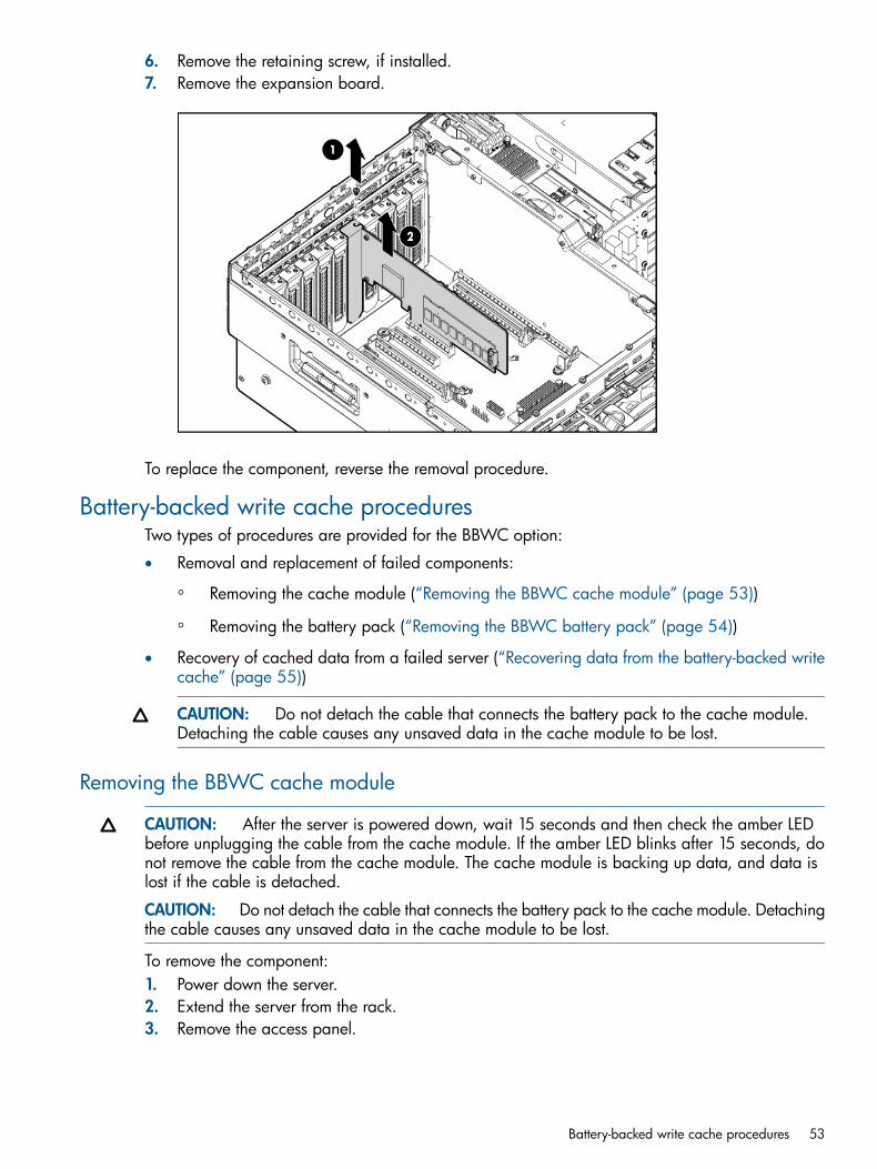
6. Remove the retaining screw, if installed.7. Remove the expansion board.
To replace the component, reverse the removal procedure.
Battery-backed write cache proceduresTwo types of procedures are provided for the BBWC option:
• Removal and replacement of failed components:
Removing the cache module (“Removing the BBWC cache module” (page 53))◦◦ Removing the battery pack (“Removing the BBWC battery pack” (page 54))
• Recovery of cached data from a failed server (“Recovering data from the battery-backed writecache” (page 55))
CAUTION: Do not detach the cable that connects the battery pack to the cache module.Detaching the cable causes any unsaved data in the cache module to be lost.
Removing the BBWC cache module
CAUTION: After the server is powered down, wait 15 seconds and then check the amber LEDbefore unplugging the cable from the cache module. If the amber LED blinks after 15 seconds, donot remove the cable from the cache module. The cache module is backing up data, and data islost if the cable is detached.
CAUTION: Do not detach the cable that connects the battery pack to the cache module. Detachingthe cable causes any unsaved data in the cache module to be lost.
To remove the component:1. Power down the server.2. Extend the server from the rack.3. Remove the access panel.
Battery-backed write cache procedures 53

4. If the existing cache is connected to a battery, observe the BBWC Status LED (“Battery packLEDs” (page 99)).• If the LED is flashing every 2 seconds, data is still trapped in the cache. Restore system
power, and then repeat the previous steps.• If the LED is not illuminated, disconnect the battery cable from the cache.
5. Disconnect the cable.6. Remove the SPI board (“Remove the SPI board” (page 56)).7. Open the cache slot latches.8. Remove the cache module.
To replace the component, reverse the removal procedure.
Removing the BBWC battery pack
CAUTION: After the server is powered down, wait 15 seconds and then check the amber LEDbefore unplugging the cable from the cache module. If the amber LED blinks after 15 seconds, donot remove the cable from the cache module. The cache module is backing up data, and data islost if the cable is detached.
CAUTION: Do not detach the cable that connects the battery pack to the cache module. Detachingthe cable causes any unsaved data in the cache module to be lost.
To remove the component:1. Power down the server.2. Extend the server from the rack.3. Remove the access panel.4. If the existing cache is connected to a battery, observe the BBWC Status LED (“Battery pack
LEDs” (page 99)).• If the LED is flashing every 2 seconds, data is still trapped in the cache. Restore system
power, and then repeat the previous steps.• If the LED is not illuminated, disconnect the battery cable from the cache.
5. Disconnect the cable.6. Remove the battery pack.
The SPI board is removed for clarity.
54 Removal and replacement procedures

To replace the component, reverse the removal procedure.
BBWC low profile I/O expander location
BBWC procedures are the same for a BBWC located in the low profile I/O expander.
Recovering data from the battery-backed write cacheIf the server fails, you can recover any data temporarily trapped in the BBWC by using the followingprocedure.
CAUTION: Before starting this procedure, read the information about protecting againstelectrostatic discharge (“Preventing electrostatic discharge” (page 21)).
Battery-backed write cache procedures 55

1. Perform one of the following:• Set up a recovery server station using an identical server model. Do not install any internal
drives or BBWC in this server. (This is the preferred option.)• Find a server that has enough empty drive bays to accommodate all the drives from the
failed server and that meets all the other requirements for drive and array migration.2. Power down the failed server. If any data is trapped in the cache module, an amber LED on
the module blinks every 15 seconds.
CAUTION: Do not detach the cable that connects the battery pack to the cache module.Detaching the cable causes any unsaved data in the cache module to be lost.
3. Transfer the hard drives from the failed server to the recovery server station.4. Remove the BBWC [cache module and battery pack (“Removing the BBWC battery pack”
(page 54))] from the failed server.5. Perform one of the following:
• Install the BBWC into an empty BBWC DIMM socket on the system board of the recoveryserver.
• Install the BBWC into an empty BBWC DIMM socket on any Smart Array Controller inthe recovery server.
6. Power up the recovery server. A 1759 POST message is displayed, stating that valid datawas flushed from the cache. This data is now stored on the drives in the recovery server. Youcan now transfer the drives (and controller, if one was used) to another server.
Remove the SPI boardTo remove the component:1. Power off the server (“Power off the server” (page 22)).2. Extend the server from the rack.3. Remove the access panel.4. Disconnect all cables from the SPI board.
NOTE: If replacing the SPI board or clearing NVRAM, you must re-enter the server serialnumber through RBSU (“Re-entering the server serial number and product ID” (page 70)).
5. Raise the levers, and lift the SPI board from the server.
56 Removal and replacement procedures

6. Remove all components from the failed SPI board.To replace the component, reverse the removal procedure.
Systems Insight Display assembly
CAUTION: When routing cables, always be sure that the cables are not in a position wherethey can be pinched or crimped.
To remove the component:1. Power off the server (“Power off the server” (page 22)).2. Extend the server from the rack.3. Remove the access panel.4. Using a T-10 Torx screwdriver, release the two locking latches on the top of the SID bezel.5. Pull the bezel up and away from the server.6. Disconnect the cable from the rear of the Systems Insight Display assembly.7. Remove the retaining screw.8. Remove the Systems Insight Display assembly.
Systems Insight Display assembly 57

To replace the component, reverse the removal procedure.
Front bezel
CAUTION: Removal of the bezel will most likely destroy the component. Have a replacementbezel on hand for immediate replacement before removing the bezel.
1. Power down the server.2. Extend the server from the rack.3. Remove the access panel.4. Remove the SID bezel (“Systems Insight Display assembly” (page 57)).5. Remove the seven screws from the right side of the chassis and eight screws from the left side
of the chassis.
6. From the left and right insertion tabs, slide the upper part of the bezel forward.
58 Removal and replacement procedures

7. Disengage the three bezel catches between the processor memory drawers, the three catcheson the lower part of the bezel, and remove the bezel.
To replace the component, reverse the removal procedure., inserting the left side tab as the bezelis placed into position.
Solid state driveTo remove the component:1. Power down the server.2. Extend the server from the rack.3. Remove the access panel.4. Disconnect the cable from the solid state drive.5. Remove the solid state drive.
Solid state drive 59

To replace the component, reverse the removal procedure.
BatteryIf the server no longer automatically displays the correct date and time, you may need to replacethe battery that provides power to the real-time clock.
WARNING! The computer contains an internal lithium manganese dioxide, a vanadium pentoxide,or an alkaline battery pack. A risk of fire and burns exists if the battery pack is not properly handled.To reduce the risk of personal injury:• Do not attempt to recharge the battery.
• Do not expose the battery to temperatures higher than 60°C (140°F).
• Do not disassemble, crush, puncture, short external contacts, or dispose of in fire or water.
• Replace only with the spare designated for this product.
To remove the component:1. Power down the server.2. Extend the server from the rack.3. Remove the access panel.4. Remove the SPI board (“Remove the SPI board” (page 56)).5. Remove the battery.
60 Removal and replacement procedures

To replace the component, reverse the removal procedure.For more information about battery replacement or proper disposal, contact an authorized reselleror an authorized service provider.
I/O expansion board
CAUTION: To prevent improper cooling and thermal damage, do not operate the server unlessall expansion slots have either an expansion slot cover or an expansion board installed.
NOTE: When either optional I/O expansion board in installed in a two-processor configuration,the second processor must be installed in socket 3.
1. Power off the server (“Power off the server” (page 22)).2. Extend the server from the rack.3. Remove the access panel.4. Release the latches on the release lever.
I/O expansion board 61
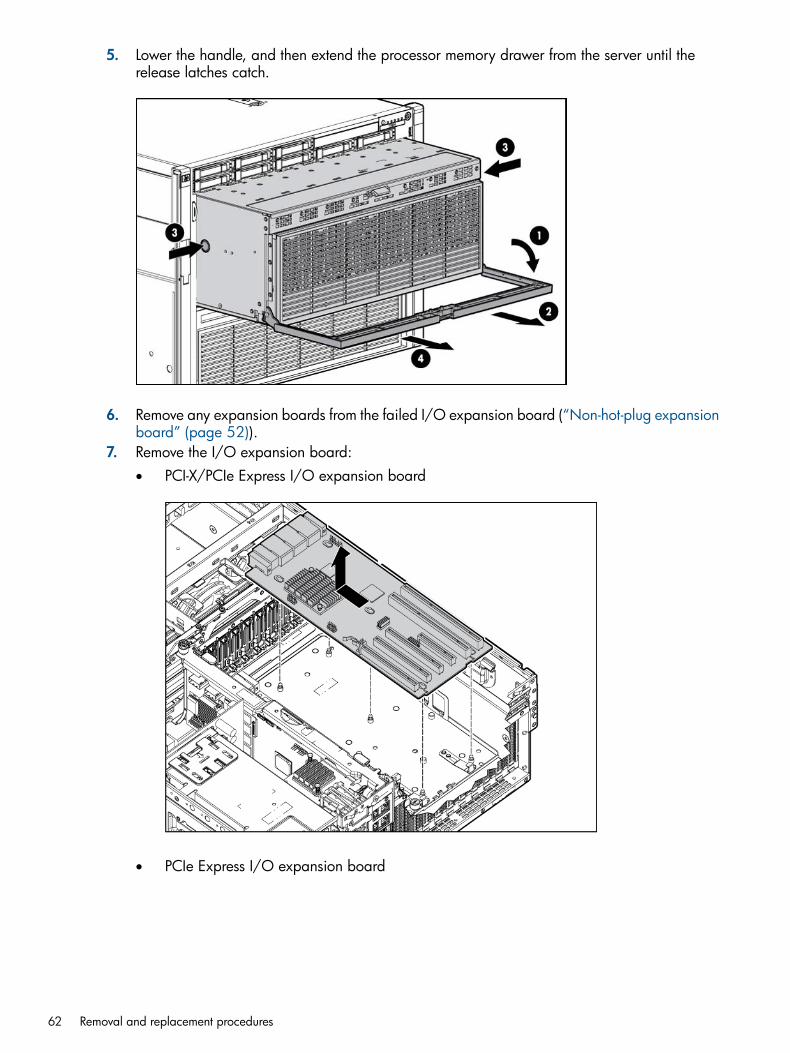
5. Lower the handle, and then extend the processor memory drawer from the server until therelease latches catch.
6. Remove any expansion boards from the failed I/O expansion board (“Non-hot-plug expansionboard” (page 52)).
7. Remove the I/O expansion board:• PCI-X/PCIe Express I/O expansion board
• PCIe Express I/O expansion board
62 Removal and replacement procedures

To replace the component, reverse the removal procedure.
Expansion board optionsIn the main I/O tray the server supports up to 11 expansion slots. The server ships with 5 PCIExpress expansion slots.
I/O expansion board 63

To support the optional expansion slots, install one of the following options into the server:
• PCI Express I/O Expansion Board—Adds six optional slots
• PCI-X/PCI Express I/O Expansion Board—Adds five optional slots
WARNING! There is not enough available PCI memory to allocate to all devices installedin the system. Devices which were not allocated requested resources may not operateproperly.This occurs during the I/O configuration phase of POST, after the System ROM hasallocated most of the available memory for some PCI devices, leaving insufficient memory forPCI devices that have not yet been configured.The above message is an indication that theHP ProLiant DL980 G7 server has encountered this MMIO limitation and does not indicatean issue with the server. It can occur when the I/O configuration of the server demandsresources beyond those which the platform architecture allows.This message is an indicationthat the HP ProLiant DL980 G7 server has encountered this MMIO limitation and does notindicate an issue with the server. It can occur when the I/O configuration of the server demandsresources beyond those which the platform architecture allows.If some PCI devices are notallocated memory and the warning message appears during POST, perform one or more ofthe following potential workarounds to allow the remaining PCI devices to receive theirrequested memory allocations:If the server operating system documentation states that it requires2GB (or more) of memory below the 4GB address boundary, do not perform Step 1 belowbecause it may result in operating system boot failure.If the operating system documentationdoes not specify its memory requirements below the 4GB boundary, the Step 1 procedurebelow may be attempted. However, if performing Step 1 results in operating system bootfailure, perform Step 1 again and change Memory Mapped I/O Options to the default valueof 2GB of Memory Mapped I/O , and then perform Step 2 below:1. Change the MMIO Settings in the ROM-Based Setup Utility (RBSU).
a. Boot the server.b. Press the F9 key during POST (when the F9 prompt appears).c. Select Advanced Options.d. Select Advanced System ROM Options.e. Select Memory Mapped I/O Options.f. Change the default selection of 2GB of Memory Mapped I/O to either 3GB of
Memory Mapped I/O or Automatically configure Memory Mapped I/O.g. Reboot the server and verify that no warning messages appear during POST. If the
operating system will not boot, perform Step 1 again and reset Memory MappedI/O Options to the default value of 2GB of Memory Mapped I/O .
2. If the warning message continues to appear, ensure that all slotted PCI devices are usingupdated firmware and drivers and reboot the server.
3. If the warning message continues to appear, determine which adapter is least critical forthe operating environment and remove or disable that adapter. Repeat this step until theserver completes POST without displaying this error message.
64 Removal and replacement procedures

NOTE: For ProLiant DL980 G7 servers, when there is an HP NC550SFP 10Gb 2-port PCIex8 Ethernet Adapter in I/O slot 9 and an HP CN1000E Converged Network Adapter in I/Oslot 10, during a network stress test (netperf), the connection in the second port of the CN1000Emay be dropped. This issue may also occur when there is an HP CN1000E ConvergedNetwork Adapter in slot 9 and a HP CN1000E Converged Network Adapter in slot 10.This issue occurs in the following scenario:1. Run a network stress test (netperf).2. Shut down the stress test and reboot the server.3. Run netperf again.4. The connections to the clients will be made at a slow rate and then finally the connection
to slot 9 and 10 will be dropped.This occurs because the ServerEngines driver is not getting enough MSI messages at driverload time. On a ProLiant DL980 system, the driver is not getting enough MSI-X interrupts, sothe system is reverting to legacy interrupt mode.For any ProLiant DL980 G7 server runningWindows Server 2008 that has either an NC550SFP in slot 9 and an HP CN1000E ConvergedNetwork Adapter in slot 10 or an HP CN1000E Converged Network Adapter in slot 9 andan HP CN1000E Converged Network Adapter in slot 10, perform the following to allownetperf to run in this configuration without connections dropping:1. Go to the Start menu, then "Run."2. Type "cmd."3. From the command prompt, type "bcdedit /set UsePhysicalDestination yes."
NOTE: When multiple LAN-On-Motherboard (LOM) ports on an NC375i Network Adapterconfigured in a ProLiant DL980 G7 server are connected to a DHCP and a PXE server, bootingfrom the PXE server may not succeed with the following error message:No filename or root path specified(There is no F12 key option available to boot from a PXEserver.)This occurs due to the PXE implementation in the adapter firmware, which is notHP-specific.his issue only occurs when more than one LOM ports are connected AND Port 2is used to boot from the PXE server. If only Port 2 is connected, the PXE boot will succeed.
NOTE: If an HP ProLiant DL980 G7 with System ROM 2010.07.27 or a ProLiant DL580G7 with System ROM 2010.08.28 is used with Integrated Lights-Out 3 (iLO 3) FirmwareVersion 1.15 (or later) and I/O cards are installed in SubIO (I/O expansion board) slots orLPIO (Low Profile PCI-e I/O expansion board) slots, then the server Power-On-Boot processmay stop responding at the point where "Inlet Ambient Temperature" is displayed.The issue has been detected with a large range of I/O cards including the HP NC522SFP10G NIC, Smart Array P212 Controller, and Smart Array P800 Controller. In addition, thismay also potentially occur when any I/O card is installed in SubIO/LPIO slots with theBIOS/iLO 3 firmware combination described above.When this occurs, there are no IntegratedManagement Log (IML) events or other indications other than the boot sequence does notprogress past "Inlet Ambient Temperature" as shown above.To prevent the server from ceasingto respond during the Power-On-Boot process, upgrade the System ROM to HP ProLiant DL980G7 System ROM 2011.01.27 (or later).
NOTE: Any HP ProLiant DL980 server configured with any of the following HP IO Acceleratorcards:
◦ 160GB SLC PCIe ioDrive (part number 600278-B21)
◦ 320GB MLC PCIe ioDrive (part number 600279-B21)
◦ 320GB SLC PCIe ioDuo (part number 600281-B21)
◦ 640GB MLC PCIe ioDuo (part number 600282-B21)
I/O expansion board 65

◦ 1.28TB MCL PCIe ioDuo (part number 641027-B21)
may experience thermal throttling when the server is running a System ROM dated July 27,2010 (2010.07.27) or July 7, 2010 under both of the following conditions:
◦ An application has sustained high WRITE-bandwidth demands to the HP IO Accelerators.
◦ High ambient (data center) temperature (>25deg C).
When the IO accelerator card begins thermal throttling, the system will display the followingwarnings: Thermal throttling activated (<junction temp in degC>)When the IO acceleratorcard stops thermal throttling, the system will display the following warning: Thermal throttlingdeactivated (<junction temp in degC>)The above warning messages will be logged as follows:
◦ For Linux operating systems in: /var/log/messages
◦ For Windows operating systems in: the Windows system event log.
To avoid the temperature messages, perform either of the following:
◦ Accept "reduced write bandwidth" when prompted by the server. (With reduced cooling,the IO Accelerator cards will self manage the critical internal component temperature tostay within specifications. With no firmware change, the IO Accelerator cards will reduceWRITE bandwidth to remain within temperature specifications. The expected WRITEbandwidth reduction is relatively small.)
◦ Upgrade the System ROM to a version dated January 27, 2011 (1/27/2011) or later.
NOTE: When the HP ProLiant DL980 G7 server is configured with the Low-profile PCIExpress I/O expansion kit (Option Part Number AM434A) and no additional I/O backplaneoptions are installed, I/O devices installed in the Low Profile I/O backplane may not function,causing the operating system to generate a machine check when attempting to access thedevices.When this occurs, a message similar to the following will be displayed in the IntegrateManagement Log (IML):Uncorrectable Machine Check Exception (Board 0, Processor 5 or 6,APIC ID 0x000000A0, Bank 0x0000000B or 0x0000000C, Status 0xFA000000'00160F0F,Address 0x00000000'00000000, Misc 0x65000000'00000090)This is targeted to beresolved in a future version of the System ROM. As a workaround, perform either of thefollowing:
◦ Remove the Low-profile PCI Express I/O expansion kit (Option Part Number AM434A)
◦ Order either of the following I/O backplane options and then add them to the server:– PCI Express I/O expansion kit option part number 588139-B21
– PCI-X / PCI Express I/O expansion kit option part number 588137-B21
NOTE: ProLiant DL980 G7 servers may be unable to provide MMIO (Memory MappedI/O) memory to all slotted PCI devices during Power-On Self-Test (POST) in large I/Oconfigurations, resulting in the following warning message:
NOTE: Five or more PCIe IO Accelerator Cards are now supported when running DL980G7 System ROM version 2011.01.27 (or later) and PCIe IO Accelerator Card firmware driverversion 2.2.3 (or later).
The server supports up to 5 low profile PCI Express expansion slots in the optional low profile PCIExpress expansion module.
66 Removal and replacement procedures

NOTE: On an HP ProLiant DL980 G7 server with a 128 logical CPU configuration, if an HPNC382T PCI Express Dual Port Multifunction Gigabit Server Adapter is located in any Low ProfileIO slot, the network connection may drop or the NIC may stop responding. This can occur whilerunning Windows Server 2008 R2 and HP Network Configuration Utility for Windows Server2008 R2 Version 10.10 or Version 10.20. To prevent network connections from dropping, upgradeto HP Network Configuration Utility for Windows Server 2008 R2 Version 10.30 (or later).
SAS backplaneTo remove the component:1. Power down the server.2. Extend the server from the rack.3. Remove the access panel.4. Remove all hard drives (“SAS/SATA hard drive” (page 22)).5. Disconnect all cables from the SAS backplane.6. Release the locking latch.7. Remove the SAS backplane.
To replace the component, reverse the removal procedure.
XNC module1. Power off the server (“Power off the server” (page 22)).2. Release the latches on the release lever.
SAS backplane 67

3. Lower the handle, and then remove the component from the server.
CAUTION: Do not replace either the SPI board, main I/O board, upper CPU board, lowerCPU board or XNC boards with new components at the same time.
CAUTION: If replacing this component with a new part, all component firmware must beupdated (“Flashing firmware using Smart Components” (page 77)) before replacing any othercomponent.
CAUTION: XNC cabling (“XNC cabling” (page 102)) is required for eight processor systems.Failure to cable the XNC will result in the lower processor memory drawer not being recognizedby the server.
To replace the component, reverse the removal procedure.
System board
WARNING! The server weighs approximately 72.6 kg–93 kg (160 lb–205 lb). To reduce therisk of injury due to the weight of the server, remove the following components before removingthe server from the rack:• Processor memory module
• Hard drives
• Power suppliesThe server weighs 21.8 kg (48 lb) with these components removed and might require twopeople to remove the server from the rack.
CAUTION: Before starting this procedure, read the information about protecting againstelectrostatic discharge (“Preventing electrostatic discharge” (page 21)).
CAUTION: Only authorized technicians trained by HP should attempt to remove the systemboard. If you believe the system board requires replacement, contact HP Technical Support beforeproceeding.
68 Removal and replacement procedures

1. Power off the server (“Power off the server” (page 22)).2. Remove the server from the rack.3. Remove the access panel.4. Remove the processor memory drawer (“Remove the upper or lower processor memory drawer
or processor memory drawer blank” (page 26)).5. Disconnect all cables from all installed expansion boards.6. Remove all expansion boards (“Non-hot-plug expansion board” (page 52)).7. Remove the SPI board (“Remove the SPI board” (page 56)).8. Remove the I/O expansion board, if installed.9. Remove the system board.
To replace a system board:1. Install the spare system board.
2. Replace all components removed from the failed system board.3. Install the access panel.
System board 69

4. Slide the server back into the rack.5. Power up the server.After you replace the system board, you must re-enter the server serial number and the product ID.1. During the server startup sequence, press the F9 key to access RBSU.2. Select the Advanced Options menu.3. Select Service Options.4. Select Serial Number. The following warnings appear:
WARNING! WARNING! WARNING! The serial number is loaded into the system during themanufacturing process and should NOT be modified. This option should only be used byqualified service personnel. This value should always match the serial number sticker locatedon the chassis.Warning: The serial number should ONLY be modified by qualified personnel. This valueshould always match the serial number located on the chassis.
5. Press the Enter key to clear the warning.6. Enter the serial number and press the Enter key.7. Select Product ID. The following warning appears:
Warning: The Product ID should ONLY be modified by qualified personnel. This value shouldalways match the Product ID on the chassis.
8. Enter the product ID and press the Enter key.9. Press the Esc key to close the menu.10. Press the Esc key to exit RBSU.11. Press the F10 key to confirm exiting RBSU. The server automatically reboots.
Re-entering the server serial number and product IDAfter you replace the SPI board, you must re-enter the server serial number and the product ID.1. During the server startup sequence, press the F9 key to access RBSU.2. Select the Advanced Options menu.3. Select Serial Number. The following warning is displayed:
Warning: The serial number should ONLY be modified by qualified service personnel. Thisvalue should always match the serial number located on the chassis.
4. Press the Enter key to clear the warning.5. Enter the serial number.6. Select Product ID. The following warning is displayed:
Warning: The Product ID should ONLY be modified by qualified service personnel. This valueshould always match the Product ID located on the chassis.
7. Enter the product ID, and press the Enter key.8. Press the Esc key to close the menu.9. Press the Esc key to exit RBSU.10. Press the F10 key to confirm exiting RBSU. The server automatically reboots.
Power backplaneTo remove the component:1. Power off the server (“Power off the server” (page 22)).2. Extend the server from the rack.3. Remove the access panel.4. Remove all power supplies (“Hot-plug power supply” (page 24)).5. Remove the XNC module (“XNC module” (page 67)).
70 Removal and replacement procedures

6. Remove the SPI board (“SPI board components” (page 96)).7. Remove the processor memory drawers (“Remove the upper or lower processor memory drawer
or processor memory drawer blank” (page 26)).8. Remove the system board (“System board” (page 68)).9. Disconnect the upper cables from the power supply backplane:
a. Disconnect the upper fan power cable.b. Remove the screws and disconnect the power cable.c. Remove the lower fan power cable from the cable management slot.
10. Disconnect the lower cables from the power supply backplane:a. Disconnect the lower fan power cable from the power backplane.b. Lift the release latch.c. Disconnect the lower power cable from the power supply backplane.
Power backplane 71
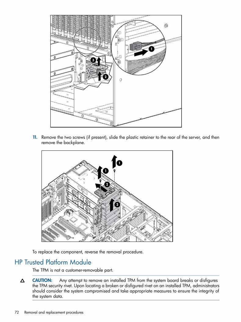
11. Remove the two screws (if present), slide the plastic retainer to the rear of the server, and thenremove the backplane.
To replace the component, reverse the removal procedure.
HP Trusted Platform ModuleThe TPM is not a customer-removable part.
CAUTION: Any attempt to remove an installed TPM from the system board breaks or disfiguresthe TPM security rivet. Upon locating a broken or disfigured rivet on an installed TPM, administratorsshould consider the system compromised and take appropriate measures to ensure the integrity ofthe system data.
72 Removal and replacement procedures

If you suspect a TPM board failure, leave the TPM installed and remove the system board (“Systemboard” (page 68)). Contact an HP authorized service provider for a replacement system boardand TPM board.
HP Trusted Platform Module 73

3 Upgrading a 4s configuration to an 8s configurationTo upgrade your DL980 G7 server from a 4s configuration to an 8s configuration:1. Verify that the current system firmware is the latest available and if necessary upgrade the
system firmware (“Flashing firmware” (page 75)).2. Power off the server and disconnect the power cords (“Power off the server” (page 22)).3. Remove the lower processor memory drawer (“Remove the upper or lower processor memory
drawer or processor memory drawer blank” (page 26)).4. Remove the processor memory drawer cover (“Remove a processor memory drawer cover”
(page 27)).5. Install processors 5 through 8 in the lower processor memory drawer. For instructions on
installing a processor, see the HP ProLiant DL980 G7 Server User Guide.6. Install DIMMs in the lower processor memory drawer (“DIMMs” (page 30)).
CAUTION: Ensure that you follow DIMM installation guidelines (“DIMM installation guidelines”(page 35)) and memory cartridge population guidelines (“Memory cartridge populationguidelines” (page 36)).Failure to follow these guidelines may result in the inability to recognize memory, memoryerrors, or reduced memory performance.
7. Connect XNC cabling (“XNC cabling” (page 102)).
CAUTION: XNC cabling is required for eight processor systems. Failure to cable the XNCwill result in the lower processor memory drawer not being recognized by the server.
8. Install any additional components, such as the power profile I/O assembly.9. Connect the power cords and power on the server. Verify server operation by monitoring
POST messages and checking the iLO IML log.
74 Upgrading a 4s configuration to an 8s configuration

4 Flashing firmwareFlashing firmware requirements
A firmware update is required when upgrading to Intel® Xeon® E7 Family processors or whenreplacing a SPI board, main I/O board, upper CPU board, lower CPU board, or XNC assemblywith a new part.
• The system firmware must be upgraded to a minimum level of HWM5.1.
• If upgrading the CPUs.The CPUs and heatsinks must be replaced with the new CPUs andheatsinks.
• The server must only contain supported I/O cards. The following cards are no longer supportedon the DL980 G7 Server with Intel Xeon E7 Family® processors.
Part numberI/O Card
435508-B21HP NC364T PCIE 4 Port 1GbE
468332-B21HP NC522SFP Dual Port 10GbE Server Adapter
488765-B21SC08Ge
To upgrade system firmware, use one of the following methods:
• Flashing firmware using Offline Update Method. This is the preferred method for all operatingsystem.
• Flashing firmware using Smart Components. This method may be used for Windows and Linuxoperating systems.
Before contacting HP, always attempt to resolve problems by completing the procedures in thisguide.
NOTE: Collect the appropriate server information and operating system information beforecontacting HP for support.
For United States and worldwide contact information, see the Contact HP website (http://www.hp.com/go/assistance).In the United States:
• To contact HP by phone, call 1-800-334-5144. For continuous quality improvement, calls maybe recorded or monitored.
If you have purchased a Care Pack (service upgrade), see the Support & Drivers website (http://www8.hp.com/us/en/support-drivers.html). If the problem cannot be resolved at the website, call
Flashing firmware requirements 75

1-800-633-3600. For more information about Care Packs, see the HP website (http://pro-aq-sama.houston.hp.com/services/cache/10950-0-0-225-121.html).
• In other locations, see the Contact HP worldwide (in English) (http://welcome.hp.com/country/us/en/contact_us.html) webpage.
CAUTION: If replacing a SPI board, main I/O board, upper CPU board, lower CPU board,or XNC assembly with a new part, all component firmware must be updated before replacingany other component. Do no replace either the SPI board, main I/O board, upper CPU board,lower CPU board, or XNC assembly with new components at the same time.
CAUTION: Physical access to the server is required for updating these components. Thisprocedure cannot be performed remotely or with automated deployment.
NOTE: Read through the entire firmware update process before beginning.
Flashing firmware using Offline UpdateThis procedure can be used for Windows, Linux, Solaris and VMware operating systems.
CAUTION: Physical access to the server is required for updating these components. This procedurecannot be performed remotely or with automated deployment. Do not use vMedia Functionality.
CAUTION: While upgrading the firmware, do not power off the server or attempt any operations.
CAUTION: All steps of this procedure must be performed in the exact order given in thisprocedure. Once the upgrade is started, complete the entire update. Do not stop at any pointduring the update.
NOTE: Read through the entire firmware update process before beginning.
NOTE: This procedure will take approximately 2 - 4 hours to complete.
1. Obtain the Flash System Programmable Logic Offline Update ISO Image and the latest BIOS(System ROM):a. Go to the Contact HP United States (http://welcome.hp.com/country/us/en/
contact_us.html) webpage.b. Select Support and Driver downloads.c. Select Drivers and Software.d. Enter a product name/number (for example: DL980), and click Search.e. Click HP ProLiant DL980 G7 Server.f. To retrieve an index of all available drivers, system management applications, BIOS,
firmware, software, and utilities, click your operating system.2. Flash BIOS (System ROM) by following the component installation instructions.3. Power down to Stand-By (dc power off).4. Using the web interface, flash iLO.5. Using the Offline Update ISO Image by following the installation instructions in the README.txt
file included in the zip file with the ISO image, flash System Programmable Logic.a. Insert the update media (CD or USB key) into the DL980 G7 server, and power up or
reset the system.b. Allow the system to boot normally; it will auto-boot into the update media.c. After several minutes you will be presented with a splash screen. Proceed with the update,
accepting each of the three updates as they occur.
76 Flashing firmware

6. Disconnect all power cables from the server, and wait at least 30 seconds.
CAUTION: After flashing the System Programmable Logic Devices, the power must cyclefor the changes to take effect. All power cables must be unplugged for at least 30 seconds toallow the components to lose their residual charge. Pressing the power button is not sufficient.
7. If installing new processors (“Processor” (page 44)), install them now.8. Connect the power cables to the server.9. Power up the server.10. HP recommends verifying post by watching POST codes through iLO IRC (bottom banner).
Flashing firmware using Smart Components
CAUTION: Physical access to the server is required for updating these components. This procedurecannot be performed remotely or with automated deployment.
NOTE: Read through the entire firmware update process before beginning.
Procedure for Windows and Linux operating systems
CAUTION: All steps of this procedure must be performed in the exact order given in thisprocedure. Once the upgrade is started, complete the entire update. Do not stop at any pointduring the update.
NOTE: While upgrading the firmware, do not power off the server or attempt any operations.
NOTE: This procedure will take approximately 2 - 4 hours to complete.
This procedure uses Smart Components. Smart Components are self-extracting executables, witha filename based on the component number.1. Obtain the latest BIOS (System ROM) and device drivers:
a. Go to the Contact HP United States (http://welcome.hp.com/country/us/en/contact_us.html) webpage.
b. Select Support and Driver downloads.c. Select Drivers and Software.d. Enter a product name/number (for example: DL980), and click Search.e. Click HP ProLiant DL980 G7 Server.f. To retrieve an index of all available drivers, system management applications, BIOS,
firmware, software, and utilities, click your operating system.2. The appropriate device driver must be installed and running before using this flash component.
CAUTION: If the appropriate device driver is not installed and running before using thisflash component, you will receive the following error message if the driver is not running. "Thesoftware is not supported for installation on this system. You must install the iLO ChannelInterface driver to use this component."
• On the Windows operating system, install the HP ProLiant iLO 3 Management ControllerDriver Package.
• On the Linux operating system, install the HP ProLiant Channel Interface Device Driverfor iLO.
3. Follow the component installation instructions to flash BIOS (System ROM).4. Power down to Stand-By.
Flashing firmware using Smart Components 77

5. Use the web interface to flash iLO.6. Power on the system.7. Boot the system to the OS.8. If running, disable SNMP agents service.
• For Windows operating systems:Run Services.a.
b. Select SNMP Service.c. Click Stop to stop the service.d. Click yes to stop the services indicated.
• For Linux operating systems, enterservice hp-snmp-agents stop
.9. Flash the FPGA using the FPGA Smart Component.
NOTE: When updating the individual components, the Smart Components will detect if thecomponent is already at the correct revision by displaying the message pictured below. Forcomponents other than is CPLD, you can select "Close" and continue with the rest of thefirmware update process. For the CPLD, you must select "install" and update the CPLD.
TIP: The estimated time for this update is 10 - 15 minutes.
78 Flashing firmware

a. Download the Smart Component to a directory on the hard drive and change to thatdirectory.• Download the FPGA firmware for the Windows operating system (ftp://ftp.hp.com/
pub/softlib2/software1/sc-windows-fw/p2013128495/v68025).• Download the FPGA firmware for the Linux operating system (ftp://ftp.hp.com/pub/
softlib2/software1/sc-linux-fw/p1486976799/v68026).b. From that drive and directory, execute the downloaded file. Linux users can execute "sh
CPxxxxxx.scexe" where CPxxxxxx.scexe represents the filename of the component. Click"Install" when prompted.
c. If the first update pass fails, retry flashing the FPGA.d. If the second update pass fails, browse to the iLO web information Diagnostics tab, and
use the Reset button to reset iLO.e. Retry flashing the FPGA.f. Upon successful update, the following dialog boxes will appear. Do not restart the server
at this time.
CAUTION: Do not power off or power down the server until the firmware for allcomponents in this procedure have been updated.
g. Click Restart Later.10. Flash the CPLD using the CPLD Smart Component.
Flashing firmware using Smart Components 79

NOTE: When updating the individual components, the Smart Components will detect if thecomponent is already at the correct revision by displaying the message pictured below. Forcomponents other than is CPLD, you can select "Close" and continue with the rest of thefirmware update process. For the CPLD, you must select "install" and update the CPLD.
TIP: The estimated time for this update is approximately one hour.
a. Download the Smart Component to a directory on the hard drive and change to thatdirectory.• Download the CPLD firmware for the Windows operating system (ftp://ftp.hp.com/
pub/softlib2/software1/sc-windows-fw/p350928355/v68911).• Download the CPLD firmware for the Linux operating system (ftp://ftp.hp.com/pub/
softlib2/software1/sc-linux-fw/p290132142/v68931).b. From that drive and directory, execute the downloaded file. Linux users can execute "sh
CPxxxxxx.scexe" where CPxxxxxx.scexe represents the filename of the component. Click"Install" when prompted.
c. If the first update pass fails, retry flashing the CPLD.d. If the second update pass fails, browse to the iLO web information Diagnostics tab and
use the Reset button to reset iLO.e. Retry flashing the CPLD.f. Upon successful update, the following dialog box will appear. Do not restart the server
at this time.
CAUTION: Do not power off or power down the server until the firmware for allcomponents in this procedure have been updated.
11. Flash the FMP using the FMP Smart Component.
NOTE: When updating the individual components, the Smart Components will detect if thecomponent is already at the correct revision by displaying the message pictured below. Forcomponents other than is CPLD, you can select "Close" and continue with the rest of thefirmware update process. For the CPLD, you must select "install" and update the CPLD.
80 Flashing firmware

TIP: The estimated time for this update is approximately one hour.
a. Download the Smart Component to a directory on the hard drive and change to thatdirectory.• Download the FMP firmware for the Windows operating system (ftp://ftp.hp.com/
pub/softlib2/software1/sc-windows-fw/p2062200202/v68009).• Download the FMP firmware for the Linux operating system (ftp://ftp.hp.com/pub/
softlib2/software1/sc-linux-fw/p1438027470/v68004).b. From that drive and directory, execute the downloaded file. Linux users can execute "sh
CPxxxxxx.scexe" where CPxxxxxx.scexe represents the filename of the component. Click"Install" when prompted.
c. If the first update pass fails, retry flashing the FMP.d. If the second update pass fails, browse to the iLO web information Diagnostics tab and
use the Reset button to reset iLO.e. Retry flashing the FMP.f. Upon successful update, the following dialog box will appear.
CAUTION: Do not power off or power down the server until the firmware for allcomponents in this procedure have been updated.
12. Shutdown the OS.13. Unplug all power cables from the server, and wait at least 30 seconds.
CAUTION: After flashing the System Programmable Logic Devices, the power must cyclefor the changes to take effect. All power cables must be unplugged for at least 30 seconds toallow the components to lose their residual charge. Pressing the power button is not sufficient.
14. If installing new processors (“Processor” (page 44)), install them now.15. Connect the power cables to the server.16. Power up the server (dc on).17. Verify post by watching post codes through iLO IRC (bottom banner). This step is optional,
but recommended.
Flashing firmware using Smart Components 81

Procedure for Solaris and VMware operating systemsFor Solaris and VMware operating systems use the Flashing firmware using Offline Update Method.
82 Flashing firmware

5 Component identificationFront panel components
DescriptionItem
Hard drive bay 11
Hard drive bay 22
Hard drive bay 33
Hard drive bay 44
Hard drive bay 55
Hard drive bay 66
Hard drive bay 77
Hard drive bay 88
Optical drive bay9
UID button and LED10
Health LED11
NIC 1 LED12
NIC 2 LED13
NIC 3 LED14
NIC 4 LED15
Power on/Standby button and LED16
SID17
USB connectors18
Video connector19
Front panel components 83

DescriptionItem
Processor memory tray (upper)20
Processor memory tray (lower)21
Front panel LEDs
StatusDescriptionItem
Blue—ActivatedUID button and LED1Blue (flashing)—Server being managedremotelyOff—Deactivated
Green—Normal (system on)Health LED2Amber (flashing)—Internal system healthdegradedRed (flashing)—Internal system healthcriticalOff—Normal (system off)
Green—Linked to networkNIC 1 LED3Green (flashing)—Linked with activityon the networkOff—No network connection
Green—Linked to networkNIC 2 LED4Green (flashing)—Linked with activityon the networkOff—No network connection
Green—Linked to networkNIC 3 LED5Green (flashing)—Linked with activityon the networkOff—No network connection
Green—Linked to networkNIC 4 LED6
84 Component identification

StatusDescriptionItem
Green (flashing)—Linked with activityon the networkOff—No network connection
Amber—System has AC power and isin standby mode.
Power on/Standby button and LED7
Green—System has AC power and ispowered on.Off—System has no AC power.
System Insight Display LEDs
DescriptionComponentLED
Green—Normal (system on)System powerPOWEROff—Normal (system off)
Green—Normal (system on)Boot progressBOOT PROGRESSGreen (flashing)—Normal (system onreset)Amber (flashing)—No POST codewithin first timeout periodRed (flashing)—No POST code withina subsequent second timeout periodOff—Normal (system off)
System Insight Display LEDs 85

DescriptionComponentLED
Green—Normal (system on)External component healthEXT HEALTHAmber (flashing)—Internal system healthdegradedRed (flashing)—Internal system healthcriticalOff—Normal (system off)
Green—System on or requesting poweron
Powering cappingPOWER CAP
Flashing amber—Power on deniedOff—Standby
Off—NormalOver temperatureOVER TEMPAmber—Failed or missing component
Off—No protectionAdvanced memory protectionAMPGreen—Protection enabledAmber—Memory failure occurredAmber (flashing)—Memoryconfiguration error
Off—NormalPower supplyPS XAmber—Failed or missing component
Off—NormalFanFAN XAmber—Failed or missing component
Off—NormalSPI board not properly seatedSPI ILKAmber—Failed or missing component
Off—NormalXNC board not properly seatedXNCAmber—Failed or missing component
Off—NormalXNC J-Link cables or managementcable
CABLEAmber—Failed or missing component
Off—NormalLower processor memory drawer notfully seated
LOWER CPU INKAmber—Failed or missing component
Off—NormalUpper processor memory drawer notfully seated
UPPER CPU ILKAmber—Failed or missing component
Off—NormalProcessorPROC XAmber—Failed or missing component
Off—NormalIndicates upper CPU tray withassociated CPUs, memory risers andDIMMs
UPPER CPUAmber—Failed or missing component
Off—NormalIndicates lower CPU tray withassociated CPUs, memory risers andDIMMs
LOWER CPUAmber—Failed or missing component
Off—NormalDIMM slotMEMORY BOARD X DIMM 1A-8DAmber—Failed or missing component
86 Component identification

Processor and memory board configuration / logical (physical) locationUpper processor memory board is shown on the left. Lower processor memory board is shown onthe right.
Hard drive LEDs
DescriptionItem
Fault/UID LED (amber/blue)1
Online LED (green)2
Hard drive LED combinations
InterpretationFault/UID LED (amber/blue)Online/activity LED (green)
The drive has failed, or a predictivefailure alert has been received for this
Alternating amber and blueOn, off, or flashing
drive; it also has been selected by amanagement application.
The drive is operating normally, and ithas been selected by a managementapplication.
Steadily blueOn, off, or flashing
A predictive failure alert has beenreceived for this drive.
Amber, flashing regularly (1 Hz)On
Replace the drive as soon as possible.
The drive is online, but it is not activecurrently.
OffOn
Do not remove the drive. Removing adrive may terminate the currentoperation and cause data loss.
Amber, flashing regularly (1 Hz)Flashing regularly (1 Hz)
The drive is part of an array that isundergoing capacity expansion orstripe migration, but a predictive failurealert has been received for this drive.To minimize the risk of data loss, donot replace the drive until the expansionor migration is complete.
Hard drive LEDs 87

InterpretationFault/UID LED (amber/blue)Online/activity LED (green)
Do not remove the drive. Removing adrive may terminate the currentoperation and cause data loss.
OffFlashing regularly (1 Hz)
The drive is rebuilding, or it is part ofan array that is undergoing capacityexpansion or stripe migration.
The drive is active, but a predictivefailure alert has been received for this
Amber, flashing regularly (1 Hz)Flashing irregularly
drive. Replace the drive as soon aspossible.
The drive is active, and it is operatingnormally.
OffFlashing irregularly
A critical fault condition has beenidentified for this drive, and the
Steadily amberOff
controller has placed it offline. Replacethe drive as soon as possible.
A predictive failure alert has beenreceived for this drive. Replace the driveas soon as possible.
Amber, flashing regularly (1 Hz)Off
The drive is offline, a spare, or notconfigured as part of an array.
OffOff
Rear panel components
DescriptionItem
Torx T-15 Tool1
iLO 3 connector2
Mouse connector3
88 Component identification

DescriptionItem
Serial connector4
NIC connector 25
NIC connector 46
UID7
NIC connector 38
NIC connector 19
Video connector10
Keyboard connector11
USB connectors12
I/O expansion slots13
Small form factor I/O expansion slots (optional)14
XNC connectors15
XNC management connector16
Power supply 817
Power supply 718
Power supply 619
Power supply 520
Power supply 421
Power supply 322
Power supply 223
Power supply 124
Rear panel components 89

Rear panel LEDs
StatusLED colorDescriptionItem
On or flashing—Networkactivity
GreeniLO3 NIC Activity LED1
Off—No network activity
On—Linked to networkGreeniLO3 NIC Link LED2Off—Not linked to network
On or flashing—Networkactivity
GreenNIC 2 Activity LED3
Off—No network activity
On—Linked to networkGreenNIC 2 Link LED4Off—Not linked to network
On or flashing—Networkactivity
GreenNIC 4 Activity LED5
Off—No network activity
On—Linked to networkGreenNIC 4 Link LED6Off—Not linked to network
90 Component identification
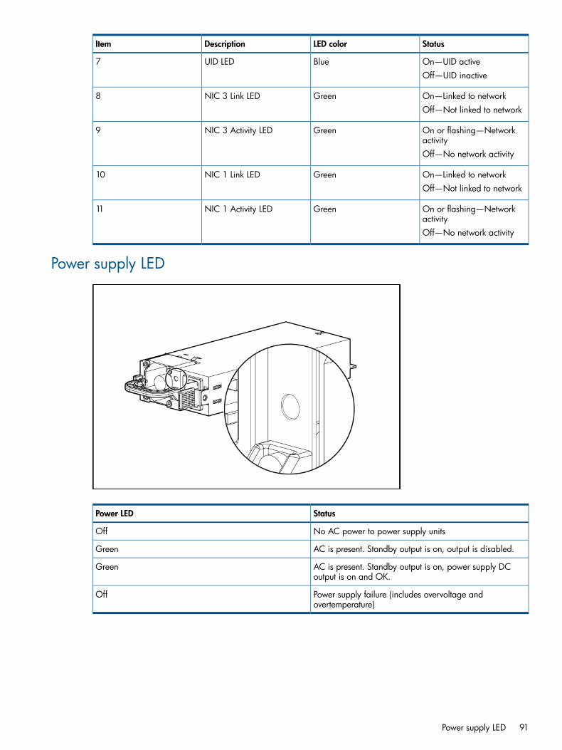
StatusLED colorDescriptionItem
On—UID activeBlueUID LED7Off—UID inactive
On—Linked to networkGreenNIC 3 Link LED8Off—Not linked to network
On or flashing—Networkactivity
GreenNIC 3 Activity LED9
Off—No network activity
On—Linked to networkGreenNIC 1 Link LED10Off—Not linked to network
On or flashing—Networkactivity
GreenNIC 1 Activity LED11
Off—No network activity
Power supply LED
StatusPower LED
No AC power to power supply unitsOff
AC is present. Standby output is on, output is disabled.Green
AC is present. Standby output is on, power supply DCoutput is on and OK.
Green
Power supply failure (includes overvoltage andovertemperature)
Off
Power supply LED 91

Fan location
92 Component identification

DescriptionItem
Fan 41
Fan 32
Fan 23
Fan 14
Fan module 65
Fan module 56
Fan location 93

System board components
DescriptionItem
Optional I/O expansion board connectors:1• PCI-X/PCI Express I/O expansion board
• PCI Express I/O expansion board
Slot 7 PCIe2 x8 (4, 2, 1)2
Slot 8 PCIe2 x8 (4, 2, 1)3
Slot 9 PCIe2 x16 (8, 4, 2, 1)4
Slot 10 PCIe2 x8 (4, 2, 1)5
Slot 11 PCIe2 x8 (8, 4, 2, 1)6
SPI board connector7
Internal USB connectors (2)8
NMI jumper9
System maintenance switch10
Optical drive connector11
Video/USB connector12
Solid state drive connector13
Power button/UID connector14
94 Component identification

System maintenance switchThe system maintenance switch (SW1) is an eight-position switch that is used for systemconfiguration. The default position for all eight positions is Off.
FunctionDescriptionPosition
Off = iLO3 security is enabled.iLO3 securityS1On = iLO3 security is disabled.
Off = System configuration can bechanged.
Configuration lockS2
On = System configuration is locked.
ReservedReservedS3
ReservedReservedS4
Off = No functionPassword protection overrideS5On = Clears power-on password andadministrator password
Off = NormalInvalidate configurationS6On = Clears NVRAM
ReservedReservedS7
ReservedReservedS8
System board components 95

SPI board components
DescriptionItem
Mini SAS connectors (2)1
SAS cache connector2
TPM connector3
Fan data connector4
RMII connector5
SD card slot6
Battery7
10Gb NIC connector8
NIC cache connector9
NIC 3 connector10
NIC 1 connector11
Video connector12
Keyboard connector13
USB connectors (2)14
iLO 3 connector15
Mouse connector16
Serial connector17
NIC 2 connector18
NIC 4 connector19
Expansion board components• PCI-X/PCI Express I/O expansion board
96 Component identification

DescriptionItem
Slot 6 PCIe2 x16 (16, 8, 4, 2, 1)1
Slot 4 PCIe2 x8 (4, 2, 1)21
Slot 3 PCIe2 x16 (16, 8, 4, 2, 1)3
Slot 2 PCI-X4
Slot 1 PCI-X51 Slot 4 is physically a x8 slot but operates electrically as a x4 slot.
• PCI Express I/O expansion board
DescriptionItem
Slot 6 PCIe2 x16 (8, 4, 2, 1)11
Slot 5 PCIe2 x16 (8, 4, 2, 1)22
Slot 4 PCIe2 x8 (4, 2, 1)33
Slot 3 PCIe2 x16 (8, 4, 2, 1)44
Slot 2 PCIe2 x16 (8, 4, 2, 1)5
Expansion board components 97

DescriptionItem5
Slot 1 PCIe1 x8 (4, 2, 1)66
1 Slots 2, 3, 5 and 6 are physically x16 slots but operate electrically as x8 slots.2 Slots 2, 3, 5 and 6 are physically x16 slots but operate electrically as x8 slots.3 Slots 1 and 4 are physically x8 slots but operate electrically as x4 slots.4 Slots 2, 3, 5 and 6 are physically x16 slots but operate electrically as x8 slots.5 Slots 2, 3, 5 and 6 are physically x16 slots but operate electrically as x8 slots.6 Slots 1 and 4 are physically x8 slots but operate electrically as x4 slots.
• Low profile I/O expansion board
DescriptionItem
Slot 12 Low profile PCIe2 x8 (4, 2, 1)1
Slot 13 Low profile PCIe2 x8 (4, 2, 1)2
Slot 14 Low profile PCIe2 x4 (2, 1)3
Slot 15 Low profile PCIe x8 (4, 2, 1)4
Slot 16 Low profile PCIe x8 (4, 2, 1)5
DIMM slot locationsEach memory module contains 8 DIMM slots. The paired banks are identified by the letters Athrough D.
98 Component identification

Device numbers
Battery pack LEDs
DescriptionColorItem
System Power LED. This LED is on whenthe system is powered up and 12 V
Green1
system power is available. This powersupply is used to maintain the batterycharge and provide supplementarypower to the cache microcontroller.
Auxiliary Power LED. This LED is onwhen 3.3V auxiliary voltage is
Green2
detected. The auxiliary voltage is usedto preserve BBWC data and isavailable any time that the systempower cords are connected to a powersupply.
Device numbers 99

DescriptionColorItem
Battery Health LED. To interpret theillumination patterns of this LED, see thefollowing table.
Amber3
BBWC Status LED. To interpret theillumination patterns of this LED, see thefollowing table.
Green4
InterpretationLED4 patternLED3 pattern
The system is powered down, and thecache contains data that has not yet
Flashing (2 Hz)Off
been written to the drives. Restoresystem power as soon as possible toprevent data loss.Data preservation time is extended anytime that 3.3 V auxiliary power isavailable, as indicated by LED 2. In theabsence of auxiliary power, batterypower alone preserves the data. Afully-charged battery can normallypreserve data for at least 2 days.The battery lifetime also depends on thecache module size. For moreinformation, see the controllerQuickSpecs on the HP website (http://www.hp.com).
The cache microcontroller is waiting forthe host controller to communicate.
Double flash, then pauseOff
The battery pack is below the minimumcharge level and is being charged.
Flashing (1 Hz)Off
Features that require a battery (such aswrite cache, capacity expansion, stripesize migration, and RAID migration) areunavailable temporarily until chargingis complete. The recharge process takesbetween 15 minutes and 2 hours,depending on the initial capacity of thebattery.
The battery pack is fully charged, andposted write data is stored in the cache.
OnOff
The battery pack is fully charged, andno posted write data exists in thecache.
OffOff
An alternating green and amberflashing pattern indicates that the cache
Flashing (1 Hz)Flashing (1 Hz)
microcontroller is executing from withinits boot loader and receiving new flashcode from the host controller.
A short circuit exists across the batteryterminals or within the battery pack.
—On
BBWC features are disabled until thebattery pack is replaced. The lifeexpectancy of a battery pack istypically more than 3 years.
An open circuit exists across the batteryterminals or within the battery pack.
—Flashing (1 Hz)
BBWC features are disabled until the
100 Component identification
InterpretationLED4 patternLED3 pattern
battery pack is replaced. The lifeexpectancy of a battery pack istypically more than 3 years.
Battery pack LEDs 101
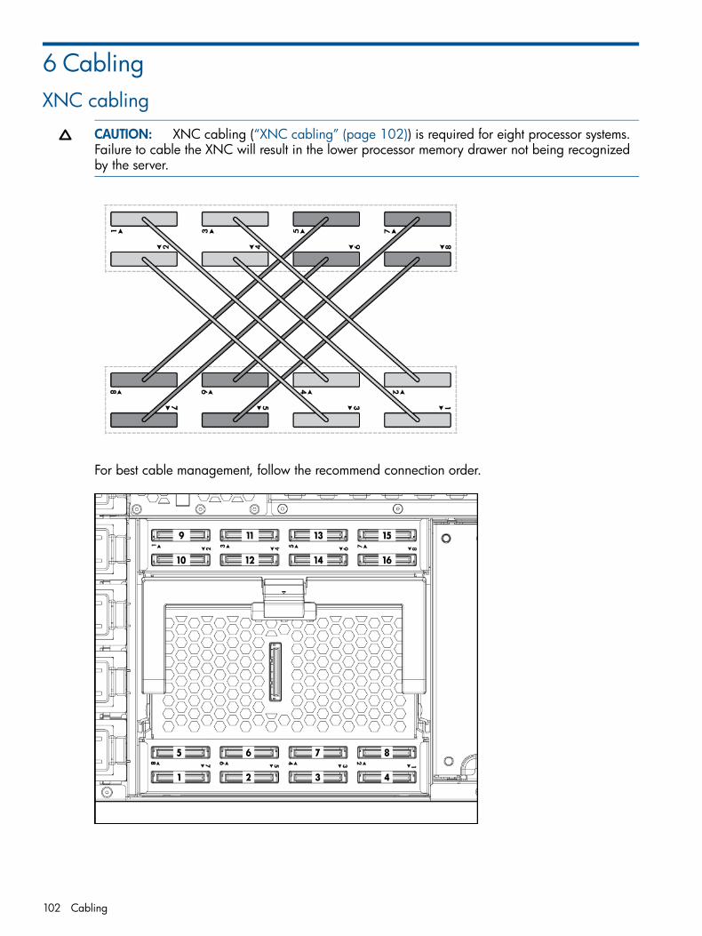
6 CablingXNC cabling
CAUTION: XNC cabling (“XNC cabling” (page 102)) is required for eight processor systems.Failure to cable the XNC will result in the lower processor memory drawer not being recognizedby the server.
For best cable management, follow the recommend connection order.
102 Cabling

1. Make connections labeled 1 through 8 in the illustration.2. Refer to cabling illustrations and table to make connections 9 though 16. For example, to
make the ninth connection, to upper board 1, use the cable connected to lower board 4.
NumberBoardConnectionsequence
Connects toNumberBoardConnectionsequence
1UpperNinthConnects4LowerSeventh
2UpperTenthConnects3LowerThird
3UpperEleventhConnects2LowerEighth
4UpperTwelfthConnects1LowerFourth
5UpperThirteenthConnects8LowerFifth
6UpperFourteenthConnects7LowerFirst
7UpperFifteenthConnects6LowerSixth
8UpperSixteenthConnects5LowerSecond
DVD-ROM drive cabling
DVD-ROM drive cabling 103

7 SpecificationsEnvironmental Specifications
ValueSpecification
—System inlet temperature
10° to 35°C (50° to 95°F) at sea level with an altitudederating of 1.0°C per every 305 m (1.8°F per every 1000
Operating
ft) above sea level to a maximum of 3050 m (10,000 ft),no direct sustained sunlight.Maximum rate of change is 10°C/hr (18°F/hr). The upperlimit may be limited by the type and number of optionsinstalled.System performance may be reduced if operating with afan fault or above 30°C (86°F).
-30° to 60°C (-22° to 140°F). Maximum rate of change is20°C/hr (36°F/hr).
Non-operating
—Relative humidity (non-condensing)
10 to 90% relative humidity (Rh), 28°C (82.4°F) maximumwet bulb temperature, non-condensing.
Operating
5 to 95% relative humidity (Rh), 38.7°C (101.7°F)maximum wet bulb temperature, non-condensing.
Non-operating
—Altitude
3050 m (10,000 ft). This value may be limited by the typeand number of options installed. Maximum allowablealtitude change rate is 457 m/min (1500 ft/min).
Operating
9144 m (30,000 ft). Maximum allowable altitude changerate is 457 m/min (1500 ft/min).
Non-operating
Listed are the declared A-Weighted sound power levels(LWAd) and declared average bystander position
Acoustic noise
A-Weighted sound pressure levels (LpAm) when the productis operating in a 23°C ambient environment. Noiseemissions were measured in accordance with ISO 7779(ECMA 74) and declared in accordance with ISO 9296(ECMA 109).
L WAd 7.5 BelsIdleL pAm 59.7 dB
L WAd 7.5 BelsOperatingL pAm 89.7 dB
—Emissions Classification (EMC)
Class AFCC rating
CISPR 22; EN55022; EN55024; FCC CFR 47, Pt 15;ICES-003; CNS13438; GB9254; K22;K24; EN61000-3-2; EN 61000-3-3; EN 60950-1; IEC 60950-1
Normative Standards
104 Specifications

Server Specifications
ValueSpecification
—Dimension
35.36 cm (13.92 in)Height
87.63 cm (34.5 in)Depth
48.26 cm (19.0 in)Width
93 kg (205 lb)Weight (maximum)
75 kg (165 lb)Weight (one hard drive, power supply and processorinstalled)
—Input requirement1
100-240 VACRated line voltage
9.3A @ 100 VACRates input current9.5A @ 108-120 VAC6.6A @ 200-240 VAC
50–60 Hz +/- 3hzRated input frequency
4600 WInput power (maximum)
14,444 BTU/hr (worst case configuration and utilization)BTUs rating (maximum)
—Power supply output (per power supply)
800 W @ 100 VACRated steady-state power900 W @ 110-120 VAC1200 W @ 200-240 VAC
950W @ 100 VACRated input power1075W @ 108–120 VAC1375W @ 200-240 VAC
960 W @ 100 VACMaximum peak power1080 W @ 110-120 VAC1440 W @ 200-240 VAC
1 To ensure the server has sufficient power during normal operation, a server configured with eight populated CPU socketsor a detected high power GPU requires high line (200 - 240 V) ac server configuration. As a precaution, if theseconfigurations are detected on a low line (100 - 127 V) ac configured server the server will halt at Power-On Self-Testwith a "Low line (100-120 VAC) power delivery is not sufficient for this configuration. High line (200-240 VAC) deliveryis required to operate the system in its current configuration" message and only boot to RBSU.
At POST, the server automatically detects whether the power supplies are connected to high-linepower or low-line power. If the server is configured with eight populated CPU sockets or a detectedhigh power GPU, the system will halt if it detects that the server is plugged into low-line power.This occurs by design because systems configured eight processors, and/ or high power graphicscards, with a large amount of memory, hard drives, or other options might require more powerthan can be provided by low-line power. POST halts this low-line configuration as a precautionagainst the server having insufficient power during operation.If a you wish to operate a server in this configuration when utilizing low-line power, the powersupply solution should be verified as sufficient using the HP Power Advisor (http://www.hp.com/go/hppoweradvisor). If the power solution is not deemed sufficient, the server may not have
Server Specifications 105

sufficient power to operate normally. If the solution is deemed sufficient, a ROM-Based Setup Utilityoption, outlined below, can be used to allow the system to operate in this configuration.If the HP Power Advisor has determined that the server can be reliably powered at low-line powerin this configuration, perform the following steps to override the Power Supply Requirements settingin ROM-Based Setup Utility (RBSU):1. When the server halts, access RBSU.2. Select "Advanced Options".3. Scroll down to "Power Requirements Override" and choose to enable it.4. Exit RBSU,which will reboot the server and should bypass the message on the subsequent
boot.
106 Specifications

8 Acronyms and abbreviationsABENDabnormal end
AMPAdvanced Memory Protection
ASRAutomatic Server Recovery
BBWCbattery-backed write cache
FBWCflash-backed write cache
GPUgraphics processing unit
IECInternational Electrotechnical Commission
iLO 3Integrated Lights-Out 3
IMLIntegrated Management Log
NVRAMnonvolatile memory
ORCAOption ROM Configuration for Arrays
PCIeperipheral component interconnect express
PCI-Xperipheral component interconnect extended
POSTPower-On Self Test
RBSUROM-Based Setup Utility
107

SASserial attached SCSI
SDSecure Digital
SFFsmall form factor
SIMSystems Insight Manager
SPIsystem peripheral interface
SSDsupport software diskette
TPMTrusted Platform Module
UIDunit identification
USBuniversal serial bus
108 Acronyms and abbreviations

9 Documentation feedbackHP is committed to providing documentation that meets your needs. To help us improve thedocumentation, send any errors, suggestions, or comments to Documentation Feedback. Includethe document title and part number, version number, or the URL when submitting your feedback.
109

Index
Symbols4s to 8s upgrade, 74
BbatteryBattery, 60SPI board components, 96
battery pack LEDs, 99battery-backed write cache (BBWC)Battery pack LEDs, 99Battery-backed write cache procedures, 53BBWC low profile I/O expander location, 55Recovering data from the battery-backed write cache,55
Removing the BBWC battery pack, 54SPI board components, 96
battery-backed write cache battery packBattery-backed write cache procedures, 53Removing the BBWC battery pack, 54
BBWC (battery-backed write cache)Battery pack LEDs, 99Battery-backed write cache procedures, 53Recovering data from the battery-backed write cache,55
Removing the BBWC battery pack, 54Removing the BBWC cache module, 53
blank, power supply, 23board, SPI (System Peripheral Interface)Re-entering the server serial number and product ID, 70Remove the SPI board, 56SPI board components, 96System board components, 94
Ccables, 102cabling, DVD-ROM drive, 103cabling, XNC, 102components, front panelFront panel components, 83Front panel LEDs, 84
components, identificationComponent identification, 83Illustrated parts catalog, 5
components, rearRear panel components, 88Rear panel LEDs, 90
components, SPI board, 96components, system boardSystem board components, 94System maintenance switch, 95
connector, iLO3, 96connector, keyboard, 96connector, mouse, 96connector, NIC, 96connector, USB, 96
connector, video, 96
Ddevice numbers, 99DIMM installation guidelinesDIMM installation guidelines, 35Hemisphere mode, 37
DIMM slot locations, 98DIMMsDIMM identification, 35Single-, dual-, and quad-rank DIMMs, 34
drives, 22DVD drive, 103DVD-ROM driveDVD-ROM drive, 23DVD-ROM drive cabling, 103
DVD-ROM drive, removing, 23
Eelectrostatic discharge, 21expansion board, 52expansion boardsExpansion board options, 63Low profile I/O expander, 50Non-hot-plug expansion board, 52
expansion slots, 94
FfansFans, 25Hot-plug power supply, 24Upper fans, 25
fans, removingFans, 25Upper fans, 25
fans, replacingFans, 25Upper fans, 25
features, 83firmware, 75firmware requirements, 75firmware update, 75firmware, updating, 75front bezel, 58
Hhard drive backplane, 67hard drive LEDsHard drive LED combinations, 87Hard drive LEDs, 87
II/O expansion boards, removing, 61iLO 3 connector, 96
110 Index

Kkeyboard connector, 96
LLED, health, 84LED, iLO 3 linkRear panel components, 88Rear panel LEDs, 90
LED, UIDFront panel LEDs, 84Rear panel LEDs, 90
LEDs, 91LEDs, battery pack, 99LEDs, front panel, 84LEDs, hard driveHard drive LED combinations, 87Hard drive LEDs, 87
LEDs, power supply, 91LEDs, rear panel, 90LEDs, Systems Insight Display, 85LEDs, unit identification (UID), 84
Mmechanical componentsIllustrated parts catalog, 5Mechanical Components, 5
memory, 34memory cartridge, 27memory module population guidelinesAdvanced ECC memory population guidelines, 39Mirrored Memory population guidelines, 40
memory options, 32memory performance optimization, 38memory requirements, 38mirrored memory, 40mouse connector, 96
NNIC connectors, 96non-hot-plug expansion boards, removing, 52NVRAM, clearing, 95
Ppower LEDs, system, 99power supplies, removing, 24power supply bays, 91power supply blank, 23power supply LEDs, 91power supply, installing, 24processor, 44processor memory moduleProcessor and memory board configuration / logical(physical) location, 87
Remove a processor memory drawer cover, 27Remove the upper or lower processor memory draweror processor memory drawer blank, 26
Rrequired tools
Removal and replacement procedures, 21Required tools, 21
Ssafety considerations, 21safety information, 21SAS backplane, 67SAS hard drive LEDsHard drive LED combinations, 87Hard drive LEDs, 87
serial connector, 96serial number, 70server asset text, 70server specificationsServer Specifications, 105Specifications, 104
server warnings and cautions, 21SID, 57Solaris environments, 82solid state drive, removing, 59specifications, environmentalEnvironmental Specifications, 104Specifications, 104
specifications, serverEnvironmental Specifications, 104Specifications, 104
SPI (System Peripheral Interface) boardRe-entering the server serial number and product ID, 70Remove the SPI board, 56SPI board components, 96System board components, 94
static electricity, 21status lights, battery pack, 99switch, system maintenance, 94system battery, 96system board componentsSystem board components, 94System maintenance switch, 95
system board replacement, 68system board switches, 95system componentsComponent identification, 83System components, 9
system maintenance switchSystem board components, 94System maintenance switch, 95
System Peripheral Interface (SPI) board, 96system power LED, 99
Tthree slot option card connectors, 94tools, 21TPM (Trusted Platform Module), 72Trusted Platform Module (TPM), 72
Uupgrade4s to 8s configuration, 74
USB connectors, 96
111

Vvideo connector, 96VMware ESX Server, configuring, 82
XXNC Module, 67
112 Index