
HP ENVY 14 Notebook PC - CNET...
106
HP ENVY 14 Notebook PC Maintenance and Service Guide
Transcript of HP ENVY 14 Notebook PC - CNET...
HP ENVY 14 Notebook PC
Maintenance and Service Guide
© Copyright 2010 Hewlett-PackardDevelopment Company, L.P.
Bluetooth is a trademark owned by itsproprietor and used by Hewlett-PackardCompany under license. Intel and Core aretrademarks of Intel Corporation in the U.S.and other countries. Microsoft, Windows,and Windows Vista are U.S. registeredtrademarks of Microsoft Corporation. SDLogo is a trademark of its proprietor.
The information contained herein is subjectto change without notice. The onlywarranties for HP products and services areset forth in the express warranty statementsaccompanying such products and services.Nothing herein should be construed asconstituting an additional warranty. HP shallnot be liable for technical or editorial errorsor omissions contained herein.
First Edition: September 2010
Document Part Number: 595069-001Revision A

MSG revision history
Revision Publication Date Description
A September 2010 Updated spare parts throughout MSG.
iii

iv MSG revision history

Safety warning notice
WARNING! To reduce the possibility of heat-related injuries or of overheating the device, do notplace the device directly on your lap or obstruct the device air vents. Use the device only on a hard,flat surface. Do not allow another hard surface, such as an adjoining optional printer, or a softsurface, such as pillows or rugs or clothing, to block airflow. Also, do not allow the AC adapter tocontact the skin or a soft surface, such as pillows or rugs or clothing, during operation. The deviceand the AC adapter comply with the user-accessible surface temperature limits defined by theInternational Standard for Safety of Information Technology Equipment (IEC 60950).
v

vi Safety warning notice

Table of contents
1 Product description ........................................................................................................................................ 1
2 External component identification ................................................................................................................ 5
Top ....................................................................................................................................................... 5
Button .................................................................................................................................. 5
Keys ..................................................................................................................................... 6
Lights ................................................................................................................................... 7
TouchPad ............................................................................................................................ 8
Display .................................................................................................................................................. 9
Front ................................................................................................................................................... 10
Left side .............................................................................................................................................. 11
Right side ........................................................................................................................................... 12
Bottom components ........................................................................................................................... 13
3 Illustrated parts catalog ............................................................................................................................... 14
Service tag ......................................................................................................................................... 14
Computer major components ............................................................................................................. 15
Door Kit .............................................................................................................................................. 20
Mass storage devices ......................................................................................................................... 20
Miscellaneous parts ............................................................................................................................ 21
Sequential part number listing ............................................................................................................ 22
4 Removal and replacement procedures ....................................................................................................... 28
Preliminary replacement requirements ............................................................................................... 28
Tools required .................................................................................................................... 28
Service considerations ....................................................................................................... 28
Plastic parts ....................................................................................................... 28
Cables and connectors ..................................................................................... 28
Drive handling ................................................................................................... 29
Grounding guidelines ......................................................................................................... 29
Electrostatic discharge damage ........................................................................ 29
Packaging and transporting guidelines ............................................. 31
Component replacement procedures ................................................................................................. 32
Service tag ......................................................................................................................... 33
Computer feet .................................................................................................................... 33
Battery ............................................................................................................................... 34
SIM .................................................................................................................................... 35
Mass storage device .......................................................................................................... 36
vii
WWAN module .................................................................................................................. 38
WLAN module .................................................................................................................... 41
RTC battery ....................................................................................................................... 45
Memory module ................................................................................................................. 46
Battery connector board .................................................................................................... 48
Top cover ........................................................................................................................... 50
Keyboard ........................................................................................................................... 52
Audio/USB board ............................................................................................................... 55
Bluetooth module ............................................................................................................... 56
SIM/WWAN board ............................................................................................................. 57
Optical drive ....................................................................................................................... 59
Power connector cable ...................................................................................................... 61
System board ..................................................................................................................... 62
Fan/heat sink assembly ..................................................................................................... 65
Processor ........................................................................................................................... 67
Speakers ............................................................................................................................ 69
Display assembly ............................................................................................................... 70
5 Setup Utility (BIOS) ....................................................................................................................................... 72
Starting Setup Utility ........................................................................................................................... 72
Using Setup Utility .............................................................................................................................. 72
Changing the language of Setup Utility ............................................................................. 72
Navigating and selecting in Setup Utility ............................................................................ 72
Displaying system information ........................................................................................... 73
Restoring factory default settings in Setup Utility .............................................................. 73
Exiting Setup Utility ............................................................................................................ 74
Updating the BIOS ............................................................................................................................. 74
Determining the BIOS version ........................................................................................... 74
Downloading a BIOS update ............................................................................................. 75
6 Specifications ................................................................................................................................................ 76
Computer specifications ..................................................................................................................... 76
14.5-inch, SVA display specifications ................................................................................................. 77
Hard drive specifications .................................................................................................................... 77
DVD±RW and CD-RW Super Multi Double-Layer Combo Drive specifications ................................. 78
7 Backup and recovery .................................................................................................................................... 79
Recovery discs ................................................................................................................................... 79
Performing a system recovery ............................................................................................................ 80
Recovering using the dedicated recovery partition ............................................................ 80
Recovering using the recovery discs ................................................................................. 80
Backing up your information ............................................................................................................... 81
Using Windows Backup and Restore ................................................................................ 81
viii
Using system restore points .............................................................................................. 82
When to create restore points ........................................................................... 82
Create a system restore point ........................................................................... 82
Restore to a previous date and time ................................................................. 82
8 Connector pin assignments ......................................................................................................................... 83
Audio-in (microphone) ........................................................................................................................ 83
Audio-out (headphone) ....................................................................................................................... 83
HDMI .................................................................................................................................................. 84
RJ-45 (network) .................................................................................................................................. 85
Universal Serial Bus ........................................................................................................................... 85
9 Power cord set requirements ...................................................................................................................... 86
Requirements for all countries ............................................................................................................ 86
Requirements for specific countries and regions ............................................................................... 87
10 Recycling ..................................................................................................................................................... 88
Battery ................................................................................................................................................ 88
Display ................................................................................................................................................ 88
Index ................................................................................................................................................................... 94
ix

x
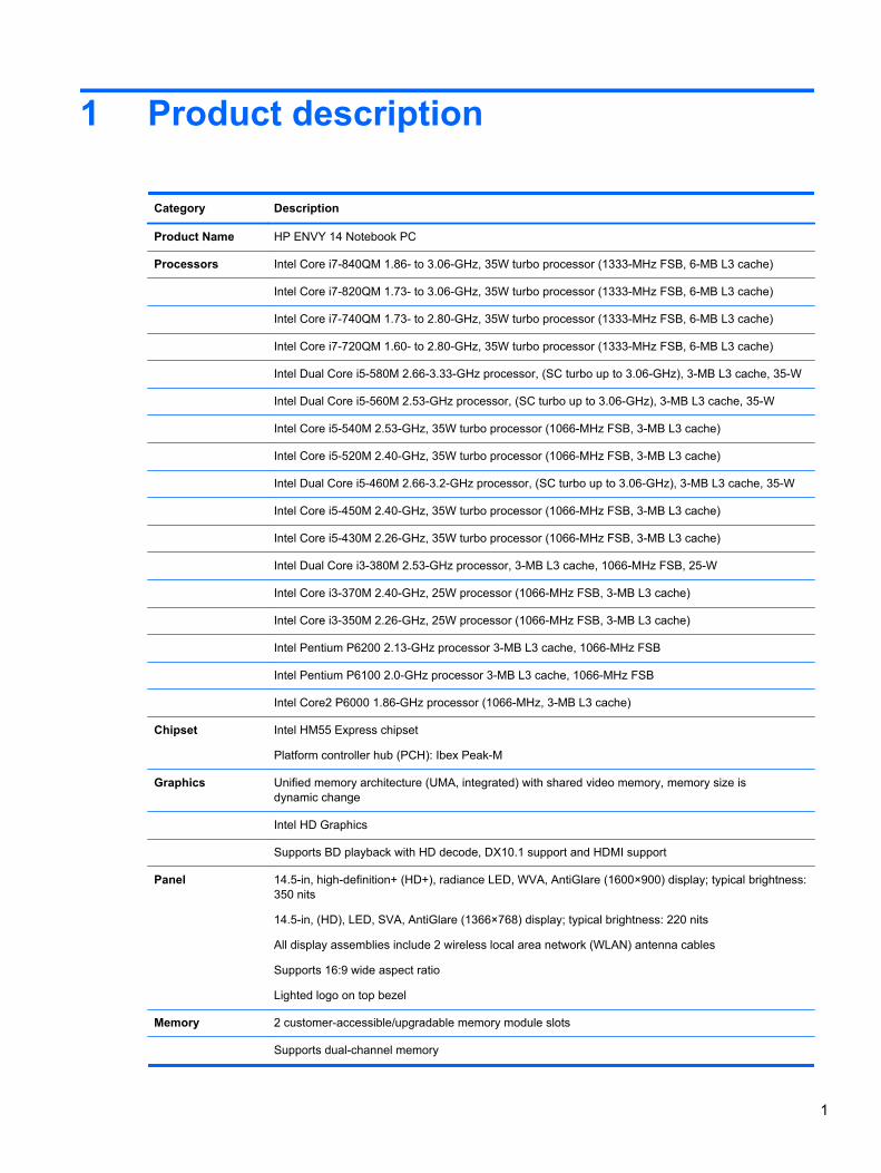
1 Product description
Category Description
Product Name HP ENVY 14 Notebook PC
Processors Intel Core i7-840QM 1.86- to 3.06-GHz, 35W turbo processor (1333-MHz FSB, 6-MB L3 cache)
Intel Core i7-820QM 1.73- to 3.06-GHz, 35W turbo processor (1333-MHz FSB, 6-MB L3 cache)
Intel Core i7-740QM 1.73- to 2.80-GHz, 35W turbo processor (1333-MHz FSB, 6-MB L3 cache)
Intel Core i7-720QM 1.60- to 2.80-GHz, 35W turbo processor (1333-MHz FSB, 6-MB L3 cache)
Intel Dual Core i5-580M 2.66-3.33-GHz processor, (SC turbo up to 3.06-GHz), 3-MB L3 cache, 35-W
Intel Dual Core i5-560M 2.53-GHz processor, (SC turbo up to 3.06-GHz), 3-MB L3 cache, 35-W
Intel Core i5-540M 2.53-GHz, 35W turbo processor (1066-MHz FSB, 3-MB L3 cache)
Intel Core i5-520M 2.40-GHz, 35W turbo processor (1066-MHz FSB, 3-MB L3 cache)
Intel Dual Core i5-460M 2.66-3.2-GHz processor, (SC turbo up to 3.06-GHz), 3-MB L3 cache, 35-W
Intel Core i5-450M 2.40-GHz, 35W turbo processor (1066-MHz FSB, 3-MB L3 cache)
Intel Core i5-430M 2.26-GHz, 35W turbo processor (1066-MHz FSB, 3-MB L3 cache)
Intel Dual Core i3-380M 2.53-GHz processor, 3-MB L3 cache, 1066-MHz FSB, 25-W
Intel Core i3-370M 2.40-GHz, 25W processor (1066-MHz FSB, 3-MB L3 cache)
Intel Core i3-350M 2.26-GHz, 25W processor (1066-MHz FSB, 3-MB L3 cache)
Intel Pentium P6200 2.13-GHz processor 3-MB L3 cache, 1066-MHz FSB
Intel Pentium P6100 2.0-GHz processor 3-MB L3 cache, 1066-MHz FSB
Intel Core2 P6000 1.86-GHz processor (1066-MHz, 3-MB L3 cache)
Chipset Intel HM55 Express chipset
Platform controller hub (PCH): Ibex Peak-M
Graphics Unified memory architecture (UMA, integrated) with shared video memory, memory size isdynamic change
Intel HD Graphics
Supports BD playback with HD decode, DX10.1 support and HDMI support
Panel 14.5-in, high-definition+ (HD+), radiance LED, WVA, AntiGlare (1600×900) display; typical brightness:350 nits
14.5-in, (HD), LED, SVA, AntiGlare (1366×768) display; typical brightness: 220 nits
All display assemblies include 2 wireless local area network (WLAN) antenna cables
Supports 16:9 wide aspect ratio
Lighted logo on top bezel
Memory 2 customer-accessible/upgradable memory module slots
Supports dual-channel memory
1
Category Description
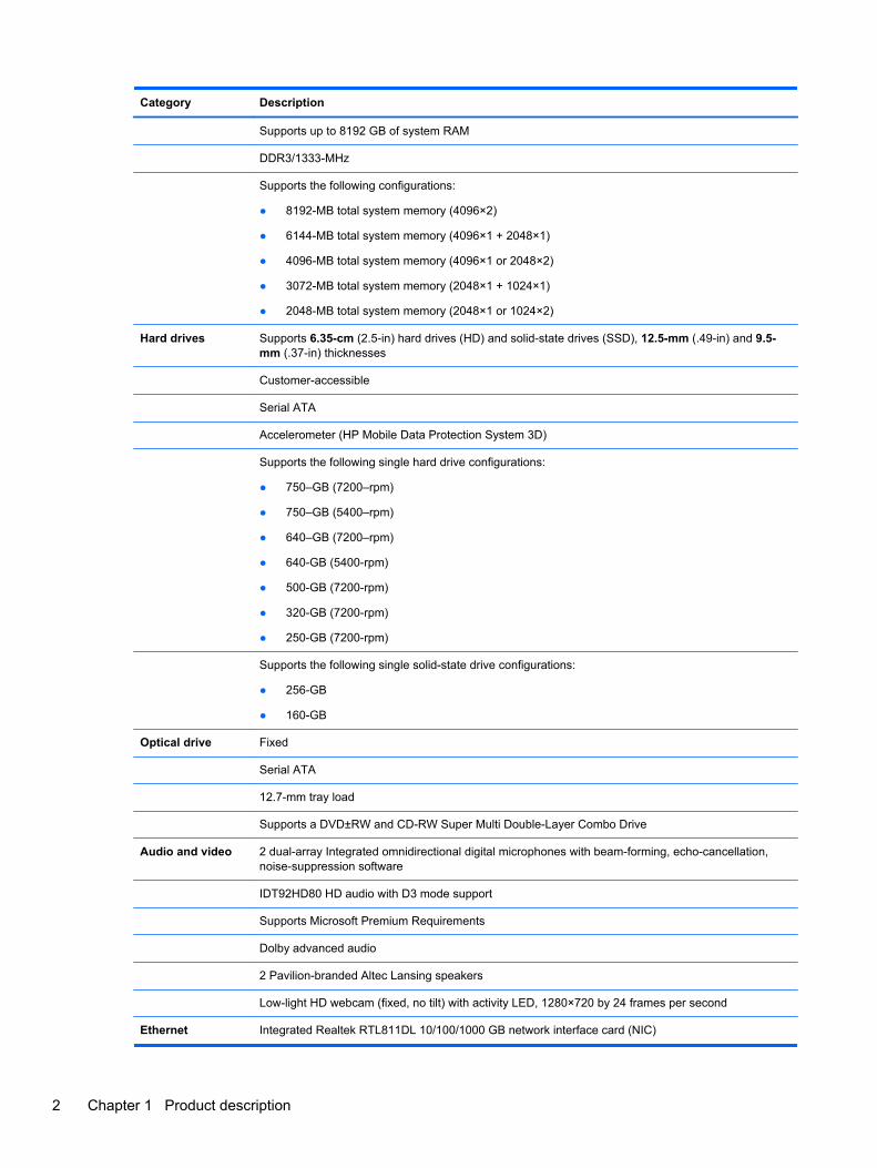
Supports up to 8192 GB of system RAM
DDR3/1333-MHz
Supports the following configurations:
● 8192-MB total system memory (4096×2)
● 6144-MB total system memory (4096×1 + 2048×1)
● 4096-MB total system memory (4096×1 or 2048×2)
● 3072-MB total system memory (2048×1 + 1024×1)
● 2048-MB total system memory (2048×1 or 1024×2)
Hard drives Supports 6.35-cm (2.5-in) hard drives (HD) and solid-state drives (SSD), 12.5-mm (.49-in) and 9.5-mm (.37-in) thicknesses
Customer-accessible
Serial ATA
Accelerometer (HP Mobile Data Protection System 3D)
Supports the following single hard drive configurations:
● 750–GB (7200–rpm)
● 750–GB (5400–rpm)
● 640–GB (7200–rpm)
● 640-GB (5400-rpm)
● 500-GB (7200-rpm)
● 320-GB (7200-rpm)
● 250-GB (7200-rpm)
Supports the following single solid-state drive configurations:
● 256-GB
● 160-GB
Optical drive Fixed
Serial ATA
12.7-mm tray load
Supports a DVD±RW and CD-RW Super Multi Double-Layer Combo Drive
Audio and video 2 dual-array Integrated omnidirectional digital microphones with beam-forming, echo-cancellation,noise-suppression software
IDT92HD80 HD audio with D3 mode support
Supports Microsoft Premium Requirements
Dolby advanced audio
2 Pavilion-branded Altec Lansing speakers
Low-light HD webcam (fixed, no tilt) with activity LED, 1280×720 by 24 frames per second
Ethernet Integrated Realtek RTL811DL 10/100/1000 GB network interface card (NIC)
2 Chapter 1 Product description
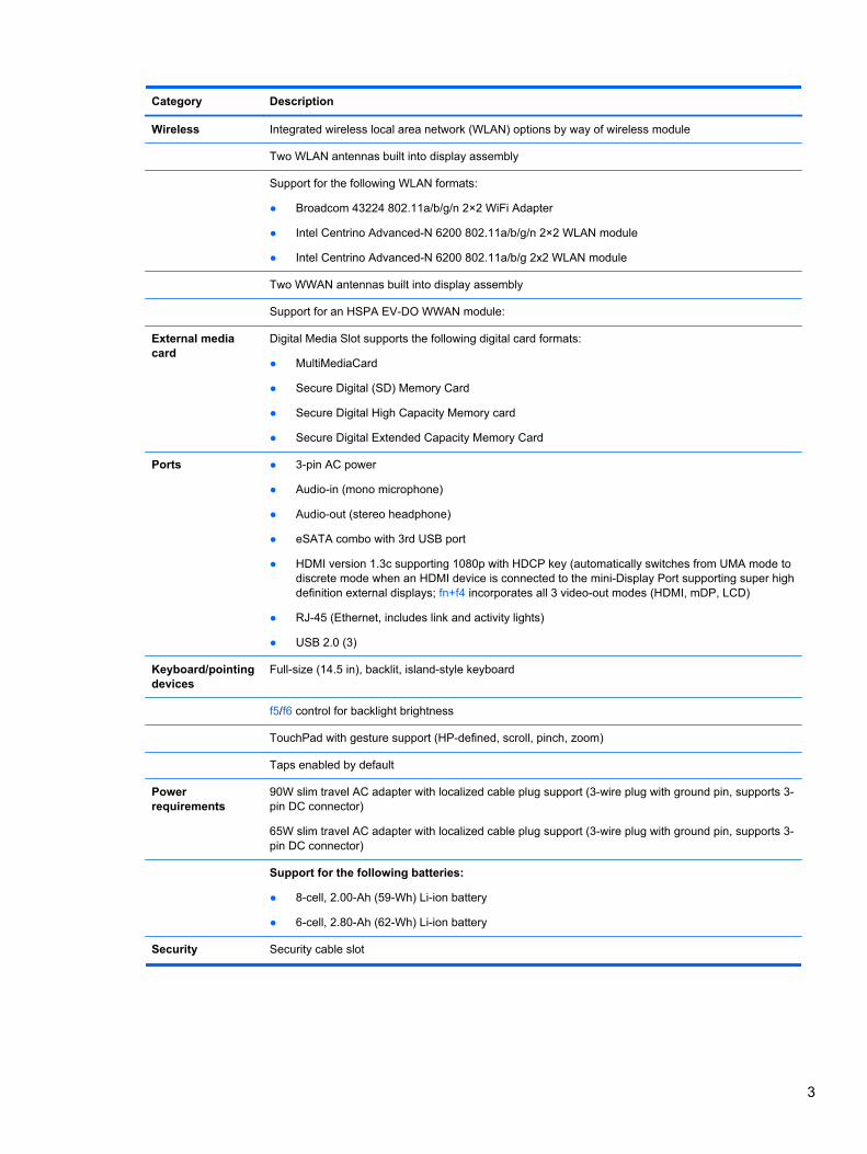
Category Description
Wireless Integrated wireless local area network (WLAN) options by way of wireless module
Two WLAN antennas built into display assembly
Support for the following WLAN formats:
● Broadcom 43224 802.11a/b/g/n 2×2 WiFi Adapter
● Intel Centrino Advanced-N 6200 802.11a/b/g/n 2×2 WLAN module
● Intel Centrino Advanced-N 6200 802.11a/b/g 2x2 WLAN module
Two WWAN antennas built into display assembly
Support for an HSPA EV-DO WWAN module:
External mediacard
Digital Media Slot supports the following digital card formats:
● MultiMediaCard
● Secure Digital (SD) Memory Card
● Secure Digital High Capacity Memory card
● Secure Digital Extended Capacity Memory Card
Ports ● 3-pin AC power
● Audio-in (mono microphone)
● Audio-out (stereo headphone)
● eSATA combo with 3rd USB port
● HDMI version 1.3c supporting 1080p with HDCP key (automatically switches from UMA mode todiscrete mode when an HDMI device is connected to the mini-Display Port supporting super highdefinition external displays; fn+f4 incorporates all 3 video-out modes (HDMI, mDP, LCD)
● RJ-45 (Ethernet, includes link and activity lights)
● USB 2.0 (3)
Keyboard/pointingdevices
Full-size (14.5 in), backlit, island-style keyboard
f5/f6 control for backlight brightness
TouchPad with gesture support (HP-defined, scroll, pinch, zoom)
Taps enabled by default
Powerrequirements
90W slim travel AC adapter with localized cable plug support (3-wire plug with ground pin, supports 3-pin DC connector)
65W slim travel AC adapter with localized cable plug support (3-wire plug with ground pin, supports 3-pin DC connector)
Support for the following batteries:
● 8-cell, 2.00-Ah (59-Wh) Li-ion battery
● 6-cell, 2.80-Ah (62-Wh) Li-ion battery
Security Security cable slot
3
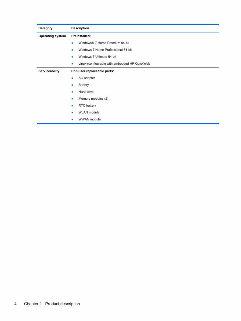
Category Description
Operating system Preinstalled:
● Windows® 7 Home Premium 64-bit
● Windows 7 Home Professional 64-bit
● Windows 7 Ultimate 64-bit
● Linux (configurable with embedded HP QuickWeb
Serviceability End-user replaceable parts:
● AC adapter
● Battery
● Hard drive
● Memory modules (2)
● RTC battery
● WLAN module
● WWAN module
4 Chapter 1 Product description
2 External component identification
Top
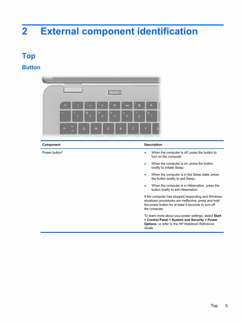
Button
Component Description
Power button* ● When the computer is off, press the button toturn on the computer.
● When the computer is on, press the buttonbriefly to initiate Sleep.
● When the computer is in the Sleep state, pressthe button briefly to exit Sleep.
● When the computer is in Hibernation, press thebutton briefly to exit Hibernation.
If the computer has stopped responding and Windowsshutdown procedures are ineffective, press and holdthe power button for at least 5 seconds to turn offthe computer.
To learn more about your power settings, select Start> Control Panel > System and Security > PowerOptions, or refer to the HP Notebook ReferenceGuide.
Top 5
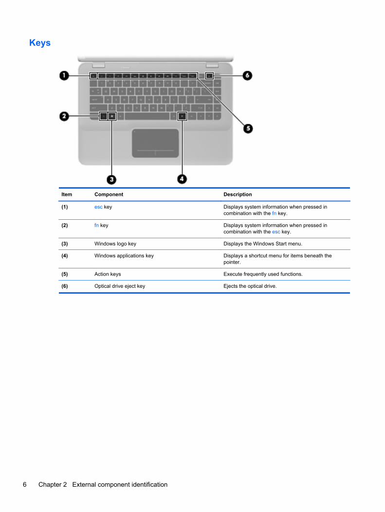
Keys
Item Component Description
(1) esc key Displays system information when pressed incombination with the fn key.
(2) fn key Displays system information when pressed incombination with the esc key.
(3) Windows logo key Displays the Windows Start menu.
(4) Windows applications key Displays a shortcut menu for items beneath thepointer.
(5) Action keys Execute frequently used functions.
(6) Optical drive eject key Ejects the optical drive.
6 Chapter 2 External component identification
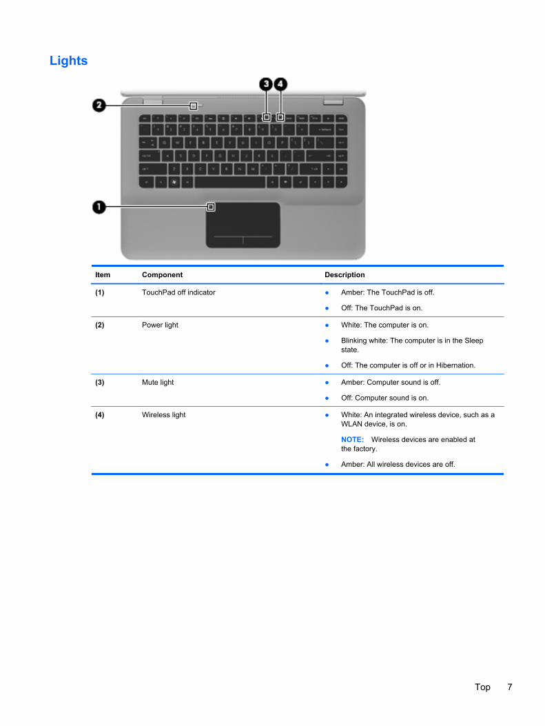
Lights
Item Component Description
(1) TouchPad off indicator ● Amber: The TouchPad is off.
● Off: The TouchPad is on.
(2) Power light ● White: The computer is on.
● Blinking white: The computer is in the Sleepstate.
● Off: The computer is off or in Hibernation.
(3) Mute light ● Amber: Computer sound is off.
● Off: Computer sound is on.
(4) Wireless light ● White: An integrated wireless device, such as aWLAN device, is on.
NOTE: Wireless devices are enabled atthe factory.
● Amber: All wireless devices are off.
Top 7

TouchPad
Item Component Description
(1) TouchPad off indicator Turns the TouchPad on and off. Quickly double-tapthe TouchPad off indicator to turn the TouchPad onand off.
(2) TouchPad zone Moves the pointer and selects or activates items onthe screen.
(3) Left TouchPad button Functions like the left button on an external mouse.
(4) Right TouchPad button Functions like the right button on an external mouse.
8 Chapter 2 External component identification
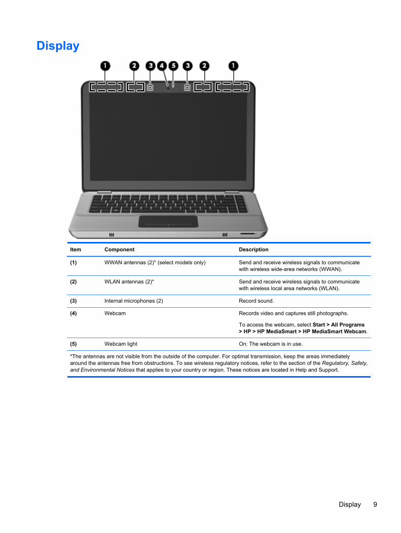
Display
Item Component Description
(1) WWAN antennas (2)* (select models only) Send and receive wireless signals to communicatewith wireless wide-area networks (WWAN).
(2) WLAN antennas (2)* Send and receive wireless signals to communicatewith wireless local area networks (WLAN).
(3) Internal microphones (2) Record sound.
(4) Webcam Records video and captures still photographs.
To access the webcam, select Start > All Programs> HP > HP MediaSmart > HP MediaSmart Webcam.
(5) Webcam light On: The webcam is in use.
*The antennas are not visible from the outside of the computer. For optimal transmission, keep the areas immediatelyaround the antennas free from obstructions. To see wireless regulatory notices, refer to the section of the Regulatory, Safety,and Environmental Notices that applies to your country or region. These notices are located in Help and Support.
Display 9
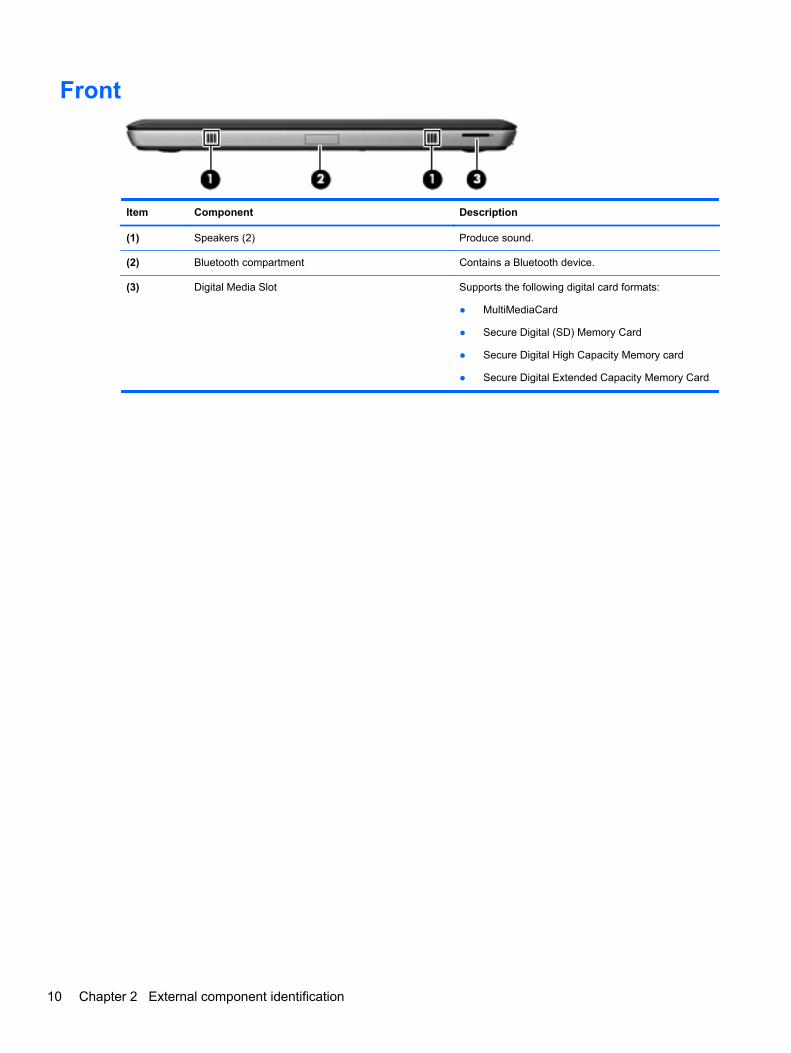
Front
Item Component Description
(1) Speakers (2) Produce sound.
(2) Bluetooth compartment Contains a Bluetooth device.
(3) Digital Media Slot Supports the following digital card formats:
● MultiMediaCard
● Secure Digital (SD) Memory Card
● Secure Digital High Capacity Memory card
● Secure Digital Extended Capacity Memory Card
10 Chapter 2 External component identification
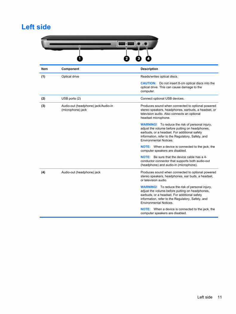
Left side
Item Component Description
(1) Optical drive Reads/writes optical discs.
CAUTION: Do not insert 8-cm optical discs into theoptical drive. This can cause damage to thecomputer.
(2) USB ports (2) Connect optional USB devices.
(3) Audio-out (headphone) jack/Audio-in(microphone) jack
Produces sound when connected to optional poweredstereo speakers, headphones, earbuds, a headset, ortelevision audio. Also connects an optionalheadset microphone.
WARNING! To reduce the risk of personal injury,adjust the volume before putting on headphones,earbuds, or a headset. For additional safetyinformation, refer to the Regulatory, Safety, andEnvironmental Notices.
NOTE: When a device is connected to the jack, thecomputer speakers are disabled.
NOTE: Be sure that the device cable has a 4-conductor connector that supports both audio-out(headphone) and audio-in (microphone).
(4) Audio-out (headphone) jack Produces sound when connected to optional poweredstereo speakers, headphones, ear buds, a headset,or television audio.
WARNING! To reduce the risk of personal injury,adjust the volume before putting on headphones,earbuds, or a headset. For additional safetyinformation, refer to the Regulatory, Safety, andEnvironmental Notices.
NOTE: When a device is connected to the jack, thecomputer speakers are disabled.
Left side 11
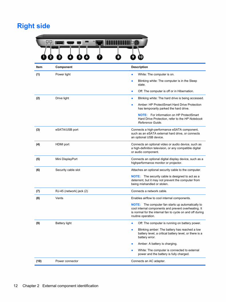
Right side
Item Component Description
(1) Power light ● White: The computer is on.
● Blinking white: The computer is in the Sleepstate.
● Off: The computer is off or in Hibernation.
(2) Drive light ● Blinking white: The hard drive is being accessed.
● Amber: HP ProtectSmart Hard Drive Protectionhas temporarily parked the hard drive.
NOTE: For information on HP ProtectSmartHard Drive Protection, refer to the HP NotebookReference Guide.
(3) eSATA/USB port Connects a high-performance eSATA component,such as an eSATA external hard drive, or connectsan optional USB device.
(4) HDMI port Connects an optional video or audio device, such asa high-definition television, or any compatible digitalor audio component.
(5) Mini DisplayPort Connects an optional digital display device, such as ahighperformance monitor or projector.
(6) Security cable slot Attaches an optional security cable to the computer.
NOTE: The security cable is designed to act as adeterrent, but it may not prevent the computer frombeing mishandled or stolen.
(7) RJ-45 (network) jack (2) Connects a network cable.
(8) Vents Enables airflow to cool internal components.
NOTE: The computer fan starts up automatically tocool internal components and prevent overheating. Itis normal for the internal fan to cycle on and off duringroutine operation.
(9) Battery light ● Off: The computer is running on battery power.
● Blinking amber: The battery has reached a lowbattery level, a critical battery level, or there is abattery error.
● Amber: A battery is charging.
● White: The computer is connected to externalpower and the battery is fully charged.
(10) Power connector Connects an AC adapter.
12 Chapter 2 External component identification
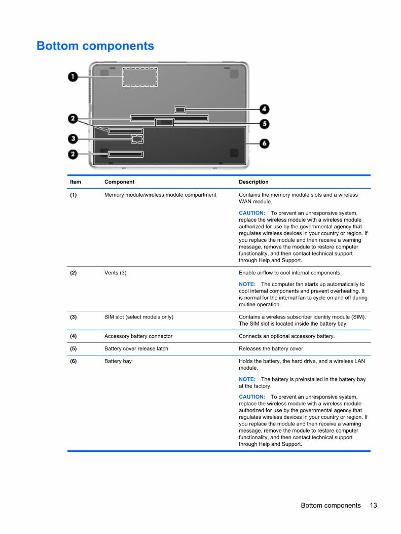
Bottom components
Item Component Description
(1) Memory module/wireless module compartment Contains the memory module slots and a wirelessWAN module.
CAUTION: To prevent an unresponsive system,replace the wireless module with a wireless moduleauthorized for use by the governmental agency thatregulates wireless devices in your country or region. Ifyou replace the module and then receive a warningmessage, remove the module to restore computerfunctionality, and then contact technical supportthrough Help and Support.
(2) Vents (3) Enable airflow to cool internal components.
NOTE: The computer fan starts up automatically tocool internal components and prevent overheating. Itis normal for the internal fan to cycle on and off duringroutine operation.
(3) SIM slot (select models only) Contains a wireless subscriber identity module (SIM).The SIM slot is located inside the battery bay.
(4) Accessory battery connector Connects an optional accessory battery.
(5) Battery cover release latch Releases the battery cover.
(6) Battery bay Holds the battery, the hard drive, and a wireless LANmodule.
NOTE: The battery is preinstalled in the battery bayat the factory.
CAUTION: To prevent an unresponsive system,replace the wireless module with a wireless moduleauthorized for use by the governmental agency thatregulates wireless devices in your country or region. Ifyou replace the module and then receive a warningmessage, remove the module to restore computerfunctionality, and then contact technical supportthrough Help and Support.
Bottom components 13
3 Illustrated parts catalog
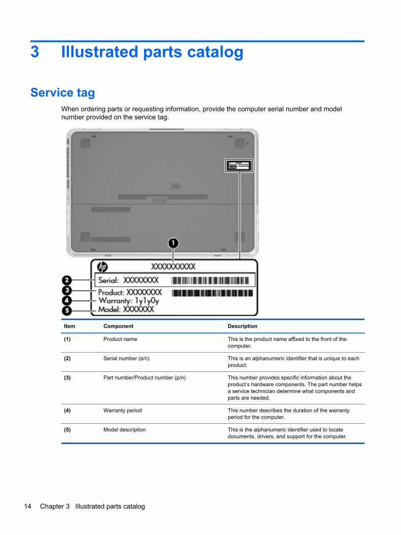
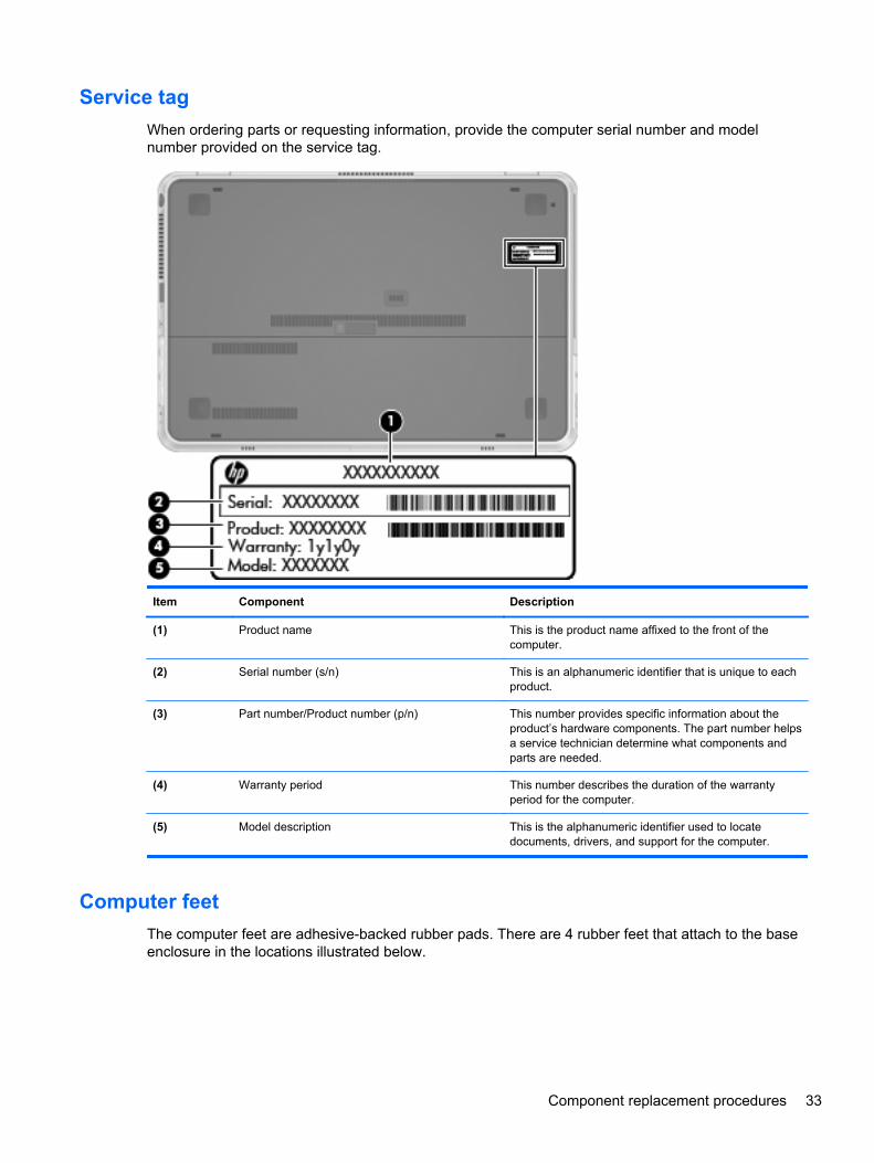
Service tagWhen ordering parts or requesting information, provide the computer serial number and modelnumber provided on the service tag.
Item Component Description
(1) Product name This is the product name affixed to the front of thecomputer.
(2) Serial number (s/n) This is an alphanumeric identifier that is unique to eachproduct.
(3) Part number/Product number (p/n) This number provides specific information about theproduct’s hardware components. The part number helpsa service technician determine what components andparts are needed.
(4) Warranty period This number describes the duration of the warrantyperiod for the computer.
(5) Model description This is the alphanumeric identifier used to locatedocuments, drivers, and support for the computer.
14 Chapter 3 Illustrated parts catalog
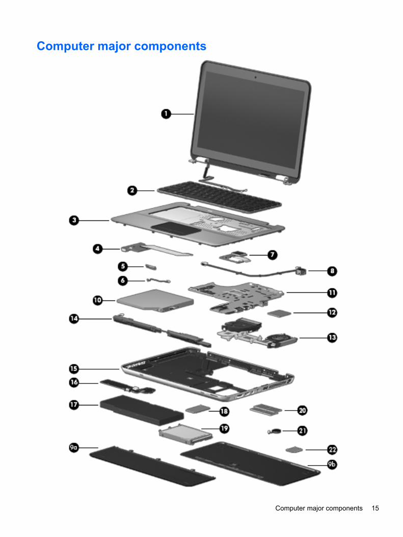
Computer major components
Computer major components 15
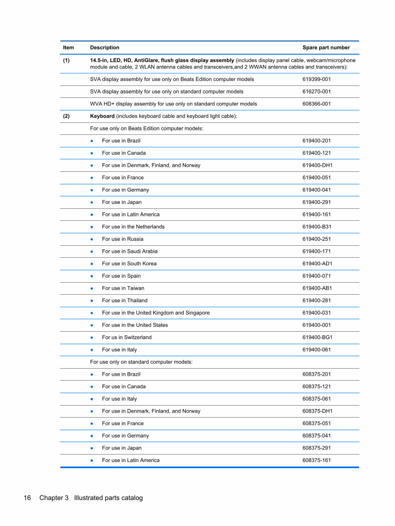
Item Description Spare part number
(1) 14.5-in, LED, HD, AntiGlare, flush glass display assembly (includes display panel cable, webcam/microphonemodule and cable, 2 WLAN antenna cables and transceivers,and 2 WWAN antenna cables and transceivers):
SVA display assembly for use only on Beats Edition computer models 619399-001
SVA display assembly for use only on standard computer models 616270-001
WVA HD+ display assembly for use only on standard computer models 608366-001
(2) Keyboard (includes keyboard cable and keyboard light cable):
For use only on Beats Edition computer models:
● For use in Brazil 619400-201
● For use in Canada 619400-121
● For use in Denmark, Finland, and Norway 619400-DH1
● For use in France 619400-051
● For use in Germany 619400-041
● For use in Japan 619400-291
● For use in Latin America 619400-161
● For use in the Netherlands 619400-B31
● For use in Russia 619400-251
● For use in Saudi Arabia 619400-171
● For use in South Korea 619400-AD1
● For use in Spain 619400-071
● For use in Taiwan 619400-AB1
● For use in Thailand 619400-281
● For use in the United Kingdom and Singapore 619400-031
● For use in the United States 619400-001
● For us in Switzerland 619400-BG1
● For use in Italy 619400-061
For use only on standard computer models:
● For use in Brazil 608375-201
● For use in Canada 608375-121
● For use in Italy 608375-061
● For use in Denmark, Finland, and Norway 608375-DH1
● For use in France 608375-051
● For use in Germany 608375-041
● For use in Japan 608375-291
● For use in Latin America 608375-161
16 Chapter 3 Illustrated parts catalog
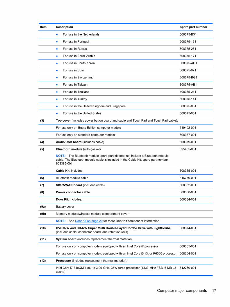
Item Description Spare part number
● For use in the Netherlands 608375-B31
● For use in Portugal 608375-131
● For use in Russia 608375-251
● For use in Saudi Arabia 608375-171
● For use in South Korea 608375-AD1
● For use in Spain 608375-071
● For use in Switzerland 608375-BG1
● For use in Taiwan 608375-AB1
● For use in Thailand 608375-281
● For use in Turkey 608375-141
● For use in the United Kingdom and Singapore 608375-031
● For use in the United States 608375-001
(3) Top cover (includes power button board and cable and TouchPad and TouchPad cable):
For use only on Beats Edition computer models 619402-001
For use only on standard computer models 608377-001
(4) Audio/USB board (includes cable) 608379-001
(5) Bluetooth module (with gasket)
NOTE: The Bluetooth module spare part kit does not include a Bluetooth modulecable. The Bluetooth module cable is included in the Cable Kit, spare part number608385-001.
625485-001
Cable Kit, includes: 608385-001
(6) Bluetooth module cable 616779-001
(7) SIM/WWAN board (includes cable) 608382-001
(8) Power connector cable 608380-001
Door Kit, includes: 608384-001
(9a) Battery cover
(9b) Memory module/wireless module compartment cover
NOTE: See Door Kit on page 20 for more Door Kit component information.
(10) DVD±RW and CD-RW Super Multi Double-Layer Combo Drive with LightScribe(includes cable, connector board, and retention rails)
608374-001
(11) System board (includes replacement thermal material):
For use only on computer models equipped with an Intel Core i7 processor 608365-001
For use only on computer models equipped with an Intel Core i5, i3, or P6000 processor 608364-001
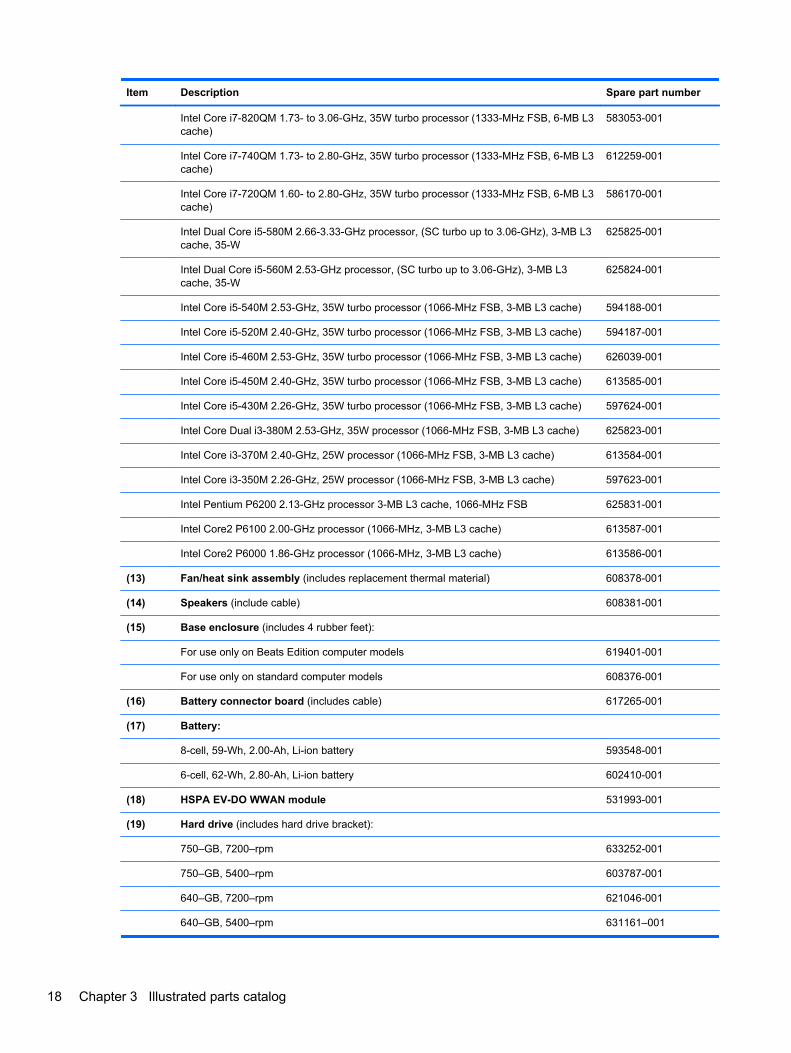
(12) Processor (includes replacement thermal material):
Intel Core i7-840QM 1.86- to 3.06-GHz, 35W turbo processor (1333-MHz FSB, 6-MB L3cache)
612260-001
Computer major components 17
Item Description Spare part number
Intel Core i7-820QM 1.73- to 3.06-GHz, 35W turbo processor (1333-MHz FSB, 6-MB L3cache)
583053-001
Intel Core i7-740QM 1.73- to 2.80-GHz, 35W turbo processor (1333-MHz FSB, 6-MB L3cache)
612259-001
Intel Core i7-720QM 1.60- to 2.80-GHz, 35W turbo processor (1333-MHz FSB, 6-MB L3cache)
586170-001
Intel Dual Core i5-580M 2.66-3.33-GHz processor, (SC turbo up to 3.06-GHz), 3-MB L3cache, 35-W
625825-001
Intel Dual Core i5-560M 2.53-GHz processor, (SC turbo up to 3.06-GHz), 3-MB L3cache, 35-W
625824-001
Intel Core i5-540M 2.53-GHz, 35W turbo processor (1066-MHz FSB, 3-MB L3 cache) 594188-001
Intel Core i5-520M 2.40-GHz, 35W turbo processor (1066-MHz FSB, 3-MB L3 cache) 594187-001
Intel Core i5-460M 2.53-GHz, 35W turbo processor (1066-MHz FSB, 3-MB L3 cache) 626039-001
Intel Core i5-450M 2.40-GHz, 35W turbo processor (1066-MHz FSB, 3-MB L3 cache) 613585-001
Intel Core i5-430M 2.26-GHz, 35W turbo processor (1066-MHz FSB, 3-MB L3 cache) 597624-001
Intel Core Dual i3-380M 2.53-GHz, 35W processor (1066-MHz FSB, 3-MB L3 cache) 625823-001
Intel Core i3-370M 2.40-GHz, 25W processor (1066-MHz FSB, 3-MB L3 cache) 613584-001
Intel Core i3-350M 2.26-GHz, 25W processor (1066-MHz FSB, 3-MB L3 cache) 597623-001
Intel Pentium P6200 2.13-GHz processor 3-MB L3 cache, 1066-MHz FSB 625831-001
Intel Core2 P6100 2.00-GHz processor (1066-MHz, 3-MB L3 cache) 613587-001
Intel Core2 P6000 1.86-GHz processor (1066-MHz, 3-MB L3 cache) 613586-001
(13) Fan/heat sink assembly (includes replacement thermal material) 608378-001
(14) Speakers (include cable) 608381-001
(15) Base enclosure (includes 4 rubber feet):
For use only on Beats Edition computer models 619401-001
For use only on standard computer models 608376-001
(16) Battery connector board (includes cable) 617265-001
(17) Battery:
8-cell, 59-Wh, 2.00-Ah, Li-ion battery 593548-001
6-cell, 62-Wh, 2.80-Ah, Li-ion battery 602410-001
(18) HSPA EV-DO WWAN module 531993-001
(19) Hard drive (includes hard drive bracket):
750–GB, 7200–rpm 633252-001
750–GB, 5400–rpm 603787-001
640–GB, 7200–rpm 621046-001
640–GB, 5400–rpm 631161–001
18 Chapter 3 Illustrated parts catalog
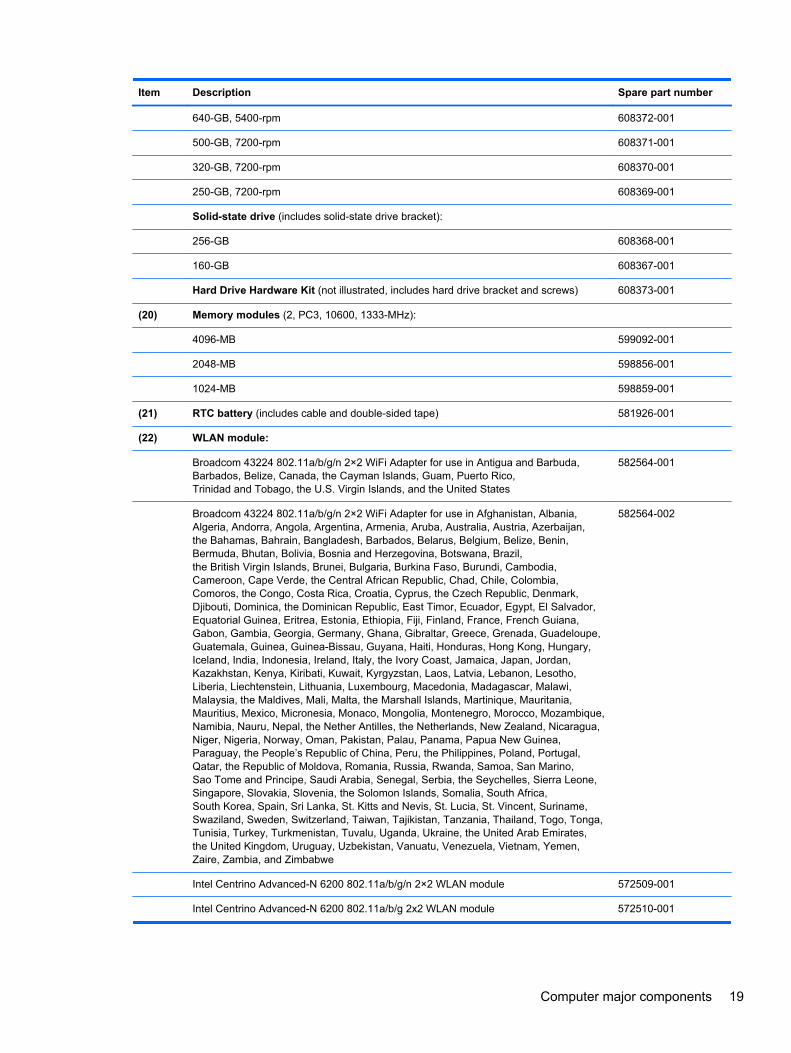
Item Description Spare part number
640-GB, 5400-rpm 608372-001
500-GB, 7200-rpm 608371-001
320-GB, 7200-rpm 608370-001
250-GB, 7200-rpm 608369-001
Solid-state drive (includes solid-state drive bracket):
256-GB 608368-001
160-GB 608367-001
Hard Drive Hardware Kit (not illustrated, includes hard drive bracket and screws) 608373-001
(20) Memory modules (2, PC3, 10600, 1333-MHz):
4096-MB 599092-001
2048-MB 598856-001
1024-MB 598859-001
(21) RTC battery (includes cable and double-sided tape) 581926-001
(22) WLAN module:
Broadcom 43224 802.11a/b/g/n 2×2 WiFi Adapter for use in Antigua and Barbuda,Barbados, Belize, Canada, the Cayman Islands, Guam, Puerto Rico,Trinidad and Tobago, the U.S. Virgin Islands, and the United States
582564-001
Broadcom 43224 802.11a/b/g/n 2×2 WiFi Adapter for use in Afghanistan, Albania,Algeria, Andorra, Angola, Argentina, Armenia, Aruba, Australia, Austria, Azerbaijan,the Bahamas, Bahrain, Bangladesh, Barbados, Belarus, Belgium, Belize, Benin,Bermuda, Bhutan, Bolivia, Bosnia and Herzegovina, Botswana, Brazil,the British Virgin Islands, Brunei, Bulgaria, Burkina Faso, Burundi, Cambodia,Cameroon, Cape Verde, the Central African Republic, Chad, Chile, Colombia,Comoros, the Congo, Costa Rica, Croatia, Cyprus, the Czech Republic, Denmark,Djibouti, Dominica, the Dominican Republic, East Timor, Ecuador, Egypt, El Salvador,Equatorial Guinea, Eritrea, Estonia, Ethiopia, Fiji, Finland, France, French Guiana,Gabon, Gambia, Georgia, Germany, Ghana, Gibraltar, Greece, Grenada, Guadeloupe,Guatemala, Guinea, Guinea-Bissau, Guyana, Haiti, Honduras, Hong Kong, Hungary,Iceland, India, Indonesia, Ireland, Italy, the Ivory Coast, Jamaica, Japan, Jordan,Kazakhstan, Kenya, Kiribati, Kuwait, Kyrgyzstan, Laos, Latvia, Lebanon, Lesotho,Liberia, Liechtenstein, Lithuania, Luxembourg, Macedonia, Madagascar, Malawi,Malaysia, the Maldives, Mali, Malta, the Marshall Islands, Martinique, Mauritania,Mauritius, Mexico, Micronesia, Monaco, Mongolia, Montenegro, Morocco, Mozambique,Namibia, Nauru, Nepal, the Nether Antilles, the Netherlands, New Zealand, Nicaragua,Niger, Nigeria, Norway, Oman, Pakistan, Palau, Panama, Papua New Guinea,Paraguay, the People’s Republic of China, Peru, the Philippines, Poland, Portugal,Qatar, the Republic of Moldova, Romania, Russia, Rwanda, Samoa, San Marino,Sao Tome and Principe, Saudi Arabia, Senegal, Serbia, the Seychelles, Sierra Leone,Singapore, Slovakia, Slovenia, the Solomon Islands, Somalia, South Africa,South Korea, Spain, Sri Lanka, St. Kitts and Nevis, St. Lucia, St. Vincent, Suriname,Swaziland, Sweden, Switzerland, Taiwan, Tajikistan, Tanzania, Thailand, Togo, Tonga,Tunisia, Turkey, Turkmenistan, Tuvalu, Uganda, Ukraine, the United Arab Emirates,the United Kingdom, Uruguay, Uzbekistan, Vanuatu, Venezuela, Vietnam, Yemen,Zaire, Zambia, and Zimbabwe
582564-002
Intel Centrino Advanced-N 6200 802.11a/b/g/n 2×2 WLAN module 572509-001
Intel Centrino Advanced-N 6200 802.11a/b/g 2x2 WLAN module 572510-001
Computer major components 19

Door Kit
Item Description Spare part number
Door Kit, includes: 608384-001
(1) Battery cover
(2) Memory module/wireless module compartment cover
Mass storage devices
Item Description Spare part number
(1) Hard drive (includes hard drive bracket):
750–GB, 7200–rpm 633252-001
750–GB, 5400–rpm 603787-001
20 Chapter 3 Illustrated parts catalog
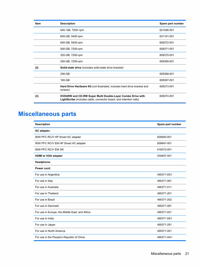
Item Description Spare part number
640–GB, 7200–rpm 621046-001
640-GB, 5400-rpm 631161-001
640-GB, 5400-rpm 608372-001
500-GB, 7200-rpm 608371-001
320-GB, 7200-rpm 608370-001
250-GB, 7200-rpm 608369-001
(2) Solid-state drive (includes solid-state drive bracket):
256-GB 608368-001
160-GB 608367-001
Hard Drive Hardware Kit (not illustrated, includes hard drive bracket andscrews)
608373-001
(3) DVD±RW and CD-RW Super Multi Double-Layer Combo Drive withLightScribe (includes cable, connector board, and retention rails)
608374-001
Miscellaneous parts
Description Spare part number
AC adapter:
90W PFC RC/V HP Smart AC adapter 609940-001
90W PFC RC/V EM HP Smart AC adapter 609947-001
90W PFC RC/V EM 3W 616072-001
HDMI to VGA adapter 530607-001
Headphone:
Power cord:
For use in Argentina 490371-D01
For use in Italy 490371-061
For use in Australia 490371-011
For use in Thailand 490371-201
For use in Brazil 490371-202
For use in Denmark 490371-081
For use in Europe, the Middle East, and Africa 490371-021
For use in India 490371-D61
For use in Japan 490371-291
For use in North America 490371-001
For use in the People's Republic of China 490371-AA1
Miscellaneous parts 21
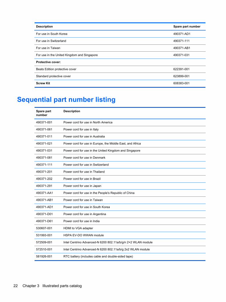
Description Spare part number
For use in South Korea 490371-AD1
For use in Switzerland 490371-111
For use in Taiwan 490371-AB1
For use in the United Kingdom and Singapore 490371-031
Protective cover:
Beats Edition protective cover 622391-001
Standard protective cover 623899-001
Screw Kit 608383-001
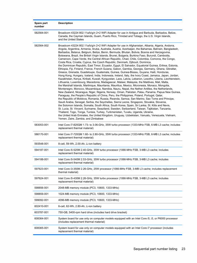
Sequential part number listing
Spare partnumber
Description
490371-001 Power cord for use in North America
490371-061 Power cord for use in Italy
490371-011 Power cord for use in Australia
490371-021 Power cord for use in Europe, the Middle East, and Africa
490371-031 Power cord for use in the United Kingdom and Singapore
490371-081 Power cord for use in Denmark
490371-111 Power cord for use in Switzerland
490371-201 Power cord for use in Thailand
490371-202 Power cord for use in Brazil
490371-291 Power cord for use in Japan
490371-AA1 Power cord for use in the People's Republic of China
490371-AB1 Power cord for use in Taiwan
490371-AD1 Power cord for use in South Korea
490371-D01 Power cord for use in Argentina
490371-D61 Power cord for use in India
530607-001 HDMI to VGA adapter
531993-001 HSPA EV-DO WWAN module
572509-001 Intel Centrino Advanced-N 6200 802.11a/b/g/n 2×2 WLAN module
572510-001 Intel Centrino Advanced-N 6200 802.11a/b/g 2x2 WLAN module
581926-001 RTC battery (includes cable and double-sided tape)
22 Chapter 3 Illustrated parts catalog
Spare partnumber
Description
582564-001 Broadcom 43224 802.11a/b/g/n 2×2 WiFi Adapter for use in Antigua and Barbuda, Barbados, Belize,Canada, the Cayman Islands, Guam, Puerto Rico, Trinidad and Tobago, the U.S. Virgin Islands,and the United States
582564-002 Broadcom 43224 802.11a/b/g/n 2×2 WiFi Adapter for use in Afghanistan, Albania, Algeria, Andorra,Angola, Argentina, Armenia, Aruba, Australia, Austria, Azerbaijan, the Bahamas, Bahrain, Bangladesh,Barbados, Belarus, Belgium, Belize, Benin, Bermuda, Bhutan, Bolivia, Bosnia and Herzegovina,Botswana, Brazil, the British Virgin Islands, Brunei, Bulgaria, Burkina Faso, Burundi, Cambodia,Cameroon, Cape Verde, the Central African Republic, Chad, Chile, Colombia, Comoros, the Congo,Costa Rica, Croatia, Cyprus, the Czech Republic, Denmark, Djibouti, Dominica,the Dominican Republic, East Timor, Ecuador, Egypt, El Salvador, Equatorial Guinea, Eritrea, Estonia,Ethiopia, Fiji, Finland, France, French Guiana, Gabon, Gambia, Georgia, Germany, Ghana, Gibraltar,Greece, Grenada, Guadeloupe, Guatemala, Guinea, Guinea-Bissau, Guyana, Haiti, Honduras,Hong Kong, Hungary, Iceland, India, Indonesia, Ireland, Italy, the Ivory Coast, Jamaica, Japan, Jordan,Kazakhstan, Kenya, Kiribati, Kuwait, Kyrgyzstan, Laos, Latvia, Lebanon, Lesotho, Liberia, Liechtenstein,Lithuania, Luxembourg, Macedonia, Madagascar, Malawi, Malaysia, the Maldives, Mali, Malta,the Marshall Islands, Martinique, Mauritania, Mauritius, Mexico, Micronesia, Monaco, Mongolia,Montenegro, Morocco, Mozambique, Namibia, Nauru, Nepal, the Nether Antilles, the Netherlands,New Zealand, Nicaragua, Niger, Nigeria, Norway, Oman, Pakistan, Palau, Panama, Papua New Guinea,Paraguay, the People’s Republic of China, Peru, the Philippines, Poland, Portugal, Qatar,the Republic of Moldova, Romania, Russia, Rwanda, Samoa, San Marino, Sao Tome and Principe,Saudi Arabia, Senegal, Serbia, the Seychelles, Sierra Leone, Singapore, Slovakia, Slovenia,the Solomon Islands, Somalia, South Africa, South Korea, Spain, Sri Lanka, St. Kitts and Nevis,St. Lucia, St. Vincent, Suriname, Swaziland, Sweden, Switzerland, Taiwan, Tajikistan, Tanzania,Thailand, Togo, Tonga, Tunisia, Turkey, Turkmenistan, Tuvalu, Uganda, Ukraine,the United Arab Emirates, the United Kingdom, Uruguay, Uzbekistan, Vanuatu, Venezuela, Vietnam,Yemen, Zaire, Zambia, and Zimbabwe
583053-001 Intel Core i7-820QM 1.73- to 3.06-GHz, 35W turbo processor (1333-MHz FSB, 6-MB L3 cache; includesreplacement thermal material)
586170-001 Intel Core i7-720QM 1.60- to 2.80-GHz, 35W turbo processor (1333-MHz FSB, 6-MB L3 cache; includesreplacement thermal material)
593548-001 8-cell, 59-Wh, 2.00-Ah, Li-ion battery
594187-001 Intel Core i5-520M 2.40-GHz, 35W turbo processor (1066-MHz FSB, 3-MB L3 cache; includesreplacement thermal material)
594188-001 Intel Core i5-540M 2.53-GHz, 35W turbo processor (1066-MHz FSB, 3-MB L3 cache; includesreplacement thermal material)
597623-001 Intel Core i3-350M 2.26-GHz, 25W processor (1066-MHz FSB, 3-MB L3 cache; includes replacementthermal material)
597624-001 Intel Core i5-430M 2.26-GHz, 35W turbo processor (1066-MHz FSB, 3-MB L3 cache; includesreplacement thermal material)
598856-001 2048-MB memory module (PC3, 10600, 1333-MHz)
598859-001 1024-MB memory module (PC3, 10600, 1333-MHz)
599092-001 4096-MB memory module (PC3, 10600, 1333-MHz)
602410-001 6-cell, 62-Wh, 2.80-Ah, Li-ion battery
603787-001 750-GB, 5400-rpm hard drive (includes hard drive bracket)
608364-001 System board for use only on computer models equipped with an Intel Core i5, i3, or P6000 processor(includes replacement thermal material)
608365-001 System board for use only on computer models equipped with an Intel Core i7 processor (includesreplacement thermal material)
Sequential part number listing 23

Spare partnumber
Description
608366-001 14.5-in, LED, HD+, AntiGlare, flush glass WVA display assembly for use only on standard computermodels (includes display panel cable, webcam/microphone module and cable, 2 WLAN antenna cablesand transceivers,and 2 WWAN antenna cables and transceivers)
608367-001 160-GB solid-state drive (includes solid-state drive bracket)
608368-001 256-GB solid-state drive (includes solid-state drive bracket)
608369-001 250-GB, 7200-rpm hard drive (includes hard drive bracket)
608370-001 320-GB, 7200-rpm hard drive (includes hard drive bracket)
608371-001 500-GB, 7200-rpm hard drive (includes hard drive bracket)
608372-001 640-GB, 5400-rpm hard drive (includes hard drive bracket)
608373-001 Hard Drive Hardware Kit (includes hard drive bracket and screws)
608374-001 DVD±RW and CD-RW Super Multi Double-Layer Combo Drive with LightScribe (includes cable,connector board, and retention rails)
608375-001 Keyboard for use only on standard computer models in the United States (includes keyboard cable andkeyboard light cable)
608375-031 Keyboard for use only on standard computer models in the United Kingdom and Singapore (includeskeyboard cable and keyboard light cable)
608375-041 Keyboard for use only on standard computer models in Germany (includes keyboard cable andkeyboard light cable)
608375-051 Keyboard for use only on standard computer models in France (includes keyboard cable and keyboardlight cable)
608375-061 Keyboard for use only on standard computer models in Italy (includes keyboard cable and keyboard lightcable)
608375-071 Keyboard for use only on standard computer models in Spain (includes keyboard cable and keyboardlight cable)
608375-121 Keyboard for use only on standard computer models in Canada (includes keyboard cable and keyboardlight cable)
608375-131 Keyboard for use only on standard computer models in Portugal (includes keyboard cable and keyboardlight cable)
608375-141 Keyboard for use only on standard computer models in Turkey (includes keyboard cable and keyboardlight cable)
608375-161 Keyboard for use only on standard computer models in Latin America (includes keyboard cable andkeyboard light cable)
608375-171 Keyboard for use only on standard computer models in Saudi Arabia (includes keyboard cable andkeyboard light cable)
608375-201 Keyboard for use only on standard computer models in Brazil (includes keyboard cable and keyboardlight cable)
608375-251 Keyboard for use only on standard computer models in Russia (includes keyboard cable and keyboardlight cable)
608375-281 Keyboard for use only on standard computer models in Thailand (includes keyboard cable and keyboardlight cable)
608375-291 Keyboard for use only on standard computer models in Japan (includes keyboard cable and keyboardlight cable)
24 Chapter 3 Illustrated parts catalog
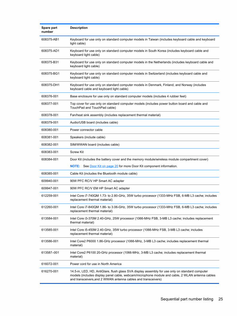
Spare partnumber
Description
608375-AB1 Keyboard for use only on standard computer models in Taiwan (includes keyboard cable and keyboardlight cable)
608375-AD1 Keyboard for use only on standard computer models in South Korea (includes keyboard cable andkeyboard light cable)
608375-B31 Keyboard for use only on standard computer models in the Netherlands (includes keyboard cable andkeyboard light cable)
608375-BG1 Keyboard for use only on standard computer models in Switzerland (includes keyboard cable andkeyboard light cable)
608375-DH1 Keyboard for use only on standard computer models in Denmark, Finland, and Norway (includeskeyboard cable and keyboard light cable)
608376-001 Base enclosure for use only on standard computer models (includes 4 rubber feet)
608377-001 Top cover for use only on standard computer models (includes power button board and cable andTouchPad and TouchPad cable)
608378-001 Fan/heat sink assembly (includes replacement thermal material)
608379-001 Audio/USB board (includes cable)
608380-001 Power connector cable
608381-001 Speakers (include cable)
608382-001 SIM/WWAN board (includes cable)
608383-001 Screw Kit
608384-001 Door Kit (includes the battery cover and the memory module/wireless module compartment cover)
NOTE: See Door Kit on page 20 for more Door Kit component information.
608385-001 Cable Kit (includes the Bluetooth module cable)
609940-001 90W PFC RC/V HP Smart AC adapter
609947-001 90W PFC RC/V EM HP Smart AC adapter
612259-001 Intel Core i7-740QM 1.73- to 2.80-GHz, 35W turbo processor (1333-MHz FSB, 6-MB L3 cache; includesreplacement thermal material)
612260-001 Intel Core i7-840QM 1.86- to 3.06-GHz, 35W turbo processor (1333-MHz FSB, 6-MB L3 cache; includesreplacement thermal material)
613584-001 Intel Core i3-370M 2.40-GHz, 25W processor (1066-MHz FSB, 3-MB L3 cache; includes replacementthermal material)
613585-001 Intel Core i5-450M 2.40-GHz, 35W turbo processor (1066-MHz FSB, 3-MB L3 cache; includesreplacement thermal material)
613586-001 Intel Core2 P6000 1.86-GHz processor (1066-MHz, 3-MB L3 cache; includes replacement thermalmaterial)
613587–001 Intel Core2 P6100 20-GHz processor (1066-MHz, 3-MB L3 cache; includes replacement thermalmaterial)
616072-001 Power cord for use in North America
616270-001 14.5-in, LED, HD, AntiGlare, flush glass SVA display assembly for use only on standard computermodels (includes display panel cable, webcam/microphone module and cable, 2 WLAN antenna cablesand transceivers,and 2 WWAN antenna cables and transceivers)
Sequential part number listing 25
Spare partnumber
Description
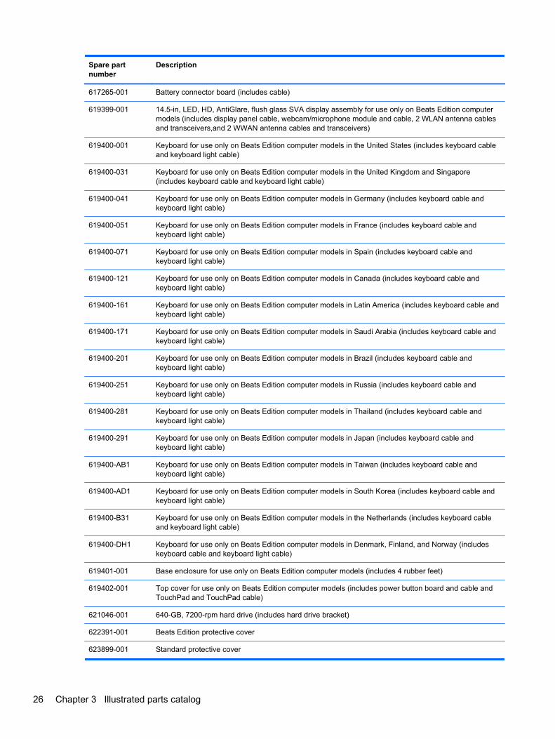
617265-001 Battery connector board (includes cable)
619399-001 14.5-in, LED, HD, AntiGlare, flush glass SVA display assembly for use only on Beats Edition computermodels (includes display panel cable, webcam/microphone module and cable, 2 WLAN antenna cablesand transceivers,and 2 WWAN antenna cables and transceivers)
619400-001 Keyboard for use only on Beats Edition computer models in the United States (includes keyboard cableand keyboard light cable)
619400-031 Keyboard for use only on Beats Edition computer models in the United Kingdom and Singapore(includes keyboard cable and keyboard light cable)
619400-041 Keyboard for use only on Beats Edition computer models in Germany (includes keyboard cable andkeyboard light cable)
619400-051 Keyboard for use only on Beats Edition computer models in France (includes keyboard cable andkeyboard light cable)
619400-071 Keyboard for use only on Beats Edition computer models in Spain (includes keyboard cable andkeyboard light cable)
619400-121 Keyboard for use only on Beats Edition computer models in Canada (includes keyboard cable andkeyboard light cable)
619400-161 Keyboard for use only on Beats Edition computer models in Latin America (includes keyboard cable andkeyboard light cable)
619400-171 Keyboard for use only on Beats Edition computer models in Saudi Arabia (includes keyboard cable andkeyboard light cable)
619400-201 Keyboard for use only on Beats Edition computer models in Brazil (includes keyboard cable andkeyboard light cable)
619400-251 Keyboard for use only on Beats Edition computer models in Russia (includes keyboard cable andkeyboard light cable)
619400-281 Keyboard for use only on Beats Edition computer models in Thailand (includes keyboard cable andkeyboard light cable)
619400-291 Keyboard for use only on Beats Edition computer models in Japan (includes keyboard cable andkeyboard light cable)
619400-AB1 Keyboard for use only on Beats Edition computer models in Taiwan (includes keyboard cable andkeyboard light cable)
619400-AD1 Keyboard for use only on Beats Edition computer models in South Korea (includes keyboard cable andkeyboard light cable)
619400-B31 Keyboard for use only on Beats Edition computer models in the Netherlands (includes keyboard cableand keyboard light cable)
619400-DH1 Keyboard for use only on Beats Edition computer models in Denmark, Finland, and Norway (includeskeyboard cable and keyboard light cable)
619401-001 Base enclosure for use only on Beats Edition computer models (includes 4 rubber feet)
619402-001 Top cover for use only on Beats Edition computer models (includes power button board and cable andTouchPad and TouchPad cable)
621046-001 640-GB, 7200-rpm hard drive (includes hard drive bracket)
622391-001 Beats Edition protective cover
623899-001 Standard protective cover
26 Chapter 3 Illustrated parts catalog
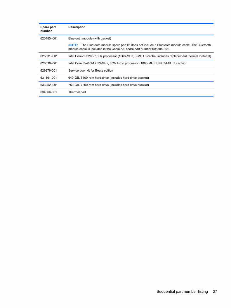
Spare partnumber
Description
625485–001 Bluetooth module (with gasket)
NOTE: The Bluetooth module spare part kit does not include a Bluetooth module cable. The Bluetoothmodule cable is included in the Cable Kit, spare part number 608385-001.
625831–001 Intel Core2 P620 2.13Hz processor (1066-MHz, 3-MB L3 cache; includes replacement thermal material)
626039–001 Intel Core i5-460M 2.53-GHz, 35W turbo processor (1066-MHz FSB, 3-MB L3 cache)
629879-001 Service door kit for Beats edition
631161-001 640-GB, 5400-rpm hard drive (includes hard drive bracket)
633252–001 750-GB, 7200-rpm hard drive (includes hard drive bracket)
634366-001 Thermal pad
Sequential part number listing 27
4 Removal and replacement procedures
Preliminary replacement requirements
Tools required
You will need the following tools to complete the removal and replacement procedures:
● Flat-bladed screwdriver
● Magnetic screwdriver
● Phillips P0 and P1 screwdrivers
Service considerations
The following sections include some of the considerations that you must keep in mind duringdisassembly and assembly procedures.
NOTE: As you remove each subassembly from the computer, place the subassembly (and allaccompanying screws) away from the work area to prevent damage.
Plastic parts
CAUTION: Using excessive force during disassembly and reassembly can damage plastic parts.Use care when handling the plastic parts. Apply pressure only at the points designated in themaintenance instructions.
Cables and connectors
CAUTION: When servicing the computer, be sure that cables are placed in their proper locationsduring the reassembly process. Improper cable placement can damage the computer.
Cables must be handled with extreme care to avoid damage. Apply only the tension required tounseat or seat the cables during removal and insertion. Handle cables by the connector wheneverpossible. In all cases, avoid bending, twisting, or tearing cables. Be sure that cables are routed insuch a way that they cannot be caught or snagged by parts being removed or replaced. Handle flexcables with extreme care; these cables tear easily.
28 Chapter 4 Removal and replacement procedures
Drive handling
CAUTION: Drives are fragile components that must be handled with care. To prevent damage tothe computer, damage to a drive, or loss of information, observe these precautions:
Before removing or inserting a hard drive, shut down the computer. If you are unsure whether thecomputer is off or in Hibernation, turn the computer on, and then shut it down through the operatingsystem.
Before handling a drive, be sure that you are discharged of static electricity. While handling a drive,avoid touching the connector.
Before removing a diskette drive or optical drive, be sure that a diskette or disc is not in the drive andbe sure that the optical drive tray is closed.
Handle drives on surfaces covered with at least one inch of shock-proof foam.
Avoid dropping drives from any height onto any surface.
After removing a hard drive, an optical drive, or a diskette drive, place it in a static-proof bag.
Avoid exposing an internal hard drive to products that have magnetic fields, such as monitors orspeakers.
Avoid exposing a drive to temperature extremes or liquids.
If a drive must be mailed, place the drive in a bubble pack mailer or other suitable form of protectivepackaging and label the package “FRAGILE.”
Grounding guidelines
Electrostatic discharge damage
Electronic components are sensitive to electrostatic discharge (ESD). Circuitry design and structuredetermine the degree of sensitivity. Networks built into many integrated circuits provide someprotection, but in many cases, ESD contains enough power to alter device parameters or melt siliconjunctions.
A discharge of static electricity from a finger or other conductor can destroy static-sensitive devices ormicrocircuitry. Even if the spark is neither felt nor heard, damage may have occurred.
An electronic device exposed to ESD may not be affected at all and can work perfectly throughout anormal cycle. Or the device may function normally for a while, then degrade in the internal layers,reducing its life expectancy.
CAUTION: To prevent damage to the computer when you are removing or installing internalcomponents, observe these precautions:
Keep components in their electrostatic-safe containers until you are ready to install them.
Before touching an electronic component, discharge static electricity by using the guidelinesdescribed in this section.
Avoid touching pins, leads, and circuitry. Handle electronic components as little as possible.
If you remove a component, place it in an electrostatic-safe container.
The following table shows how humidity affects the electrostatic voltage levels generated by differentactivities.
CAUTION: A product can be degraded by as little as 700 V.
Preliminary replacement requirements 29

Typical electrostatic voltage levels
Relative humidity
Event 10% 40% 55%
Walking across carpet 35,000 V 15,000 V 7,500 V
Walking across vinyl floor 12,000 V 5,000 V 3,000 V
Motions of bench worker 6,000 V 800 V 400 V
Removing DIPS from plastic tube 2,000 V 700 V 400 V
Removing DIPS from vinyl tray 11,500 V 4,000 V 2,000 V
Removing DIPS from Styrofoam 14,500 V 5,000 V 3,500 V
Removing bubble pack from PCB 26,500 V 20,000 V 7,000 V
Packing PCBs in foam-lined box 21,000 V 11,000 V 5,000 V
30 Chapter 4 Removal and replacement procedures
Packaging and transporting guidelines
Follow these grounding guidelines when packaging and transporting equipment:
● To avoid hand contact, transport products in static-safe tubes, bags, or boxes.
● Protect ESD-sensitive parts and assemblies with conductive or approved containers orpackaging.
● Keep ESD-sensitive parts in their containers until the parts arrive at static-free workstations.
● Place items on a grounded surface before removing items from their containers.
● Always be properly grounded when touching a component or assembly.
● Store reusable ESD-sensitive parts from assemblies in protective packaging or nonconductivefoam.
● Use transporters and conveyors made of antistatic belts and roller bushings. Be sure thatmechanized equipment used for moving materials is wired to ground and that proper materialsare selected to avoid static charging. When grounding is not possible, use an ionizer to dissipateelectric charges.
Workstation guidelines
Follow these grounding workstation guidelines:
● Cover the workstation with approved static-shielding material.
● Use a wrist strap connected to a properly grounded work surface and use properly groundedtools and equipment.
● Use conductive field service tools, such as cutters, screwdrivers, and vacuums.
● When fixtures must directly contact dissipative surfaces, use fixtures made only of static-safematerials.
● Keep the work area free of nonconductive materials, such as ordinary plastic assembly aids andStyrofoam.
● Handle ESD-sensitive components, parts, and assemblies by the case or PCM laminate. Handlethese items only at static-free workstations.
● Avoid contact with pins, leads, or circuitry.
● Turn off power and input signals before inserting or removing connectors or test equipment.
Preliminary replacement requirements 31
Equipment guidelines
Grounding equipment must include either a wrist strap or a foot strap at a grounded workstation.
● When seated, wear a wrist strap connected to a grounded system. Wrist straps are flexiblestraps with a minimum of one megohm ±10% resistance in the ground cords. To provide properground, wear a strap snugly against the skin at all times. On grounded mats with banana-plugconnectors, use alligator clips to connect a wrist strap.
● When standing, use foot straps and a grounded floor mat. Foot straps (heel, toe, or boot straps)can be used at standing workstations and are compatible with most types of shoes or boots. Onconductive floors or dissipative floor mats, use foot straps on both feet with a minimum of onemegohm resistance between the operator and ground. To be effective, the conductive must beworn in contact with the skin.
The following grounding equipment is recommended to prevent electrostatic damage:
● Antistatic tape
● Antistatic smocks, aprons, and sleeve protectors
● Conductive bins and other assembly or soldering aids
● Nonconductive foam
● Conductive tabletop workstations with ground cords of one megohm resistance
● Static-dissipative tables or floor mats with hard ties to the ground
● Field service kits
● Static awareness labels
● Material-handling packages
● Nonconductive plastic bags, tubes, or boxes
● Metal tote boxes
● Electrostatic voltage levels and protective materials
The following table lists the shielding protection provided by antistatic bags and floor mats.
Material Use Voltage protection level
Antistatic plastics Bags 1,500 V
Carbon-loaded plastic Floor mats 7,500 V
Metallized laminate Floor mats 5,000 V
Component replacement proceduresThis chapter provides removal and replacement procedures.
There are as many as 67 screws that must be removed, replaced, or loosened when servicing thecomputer. Make special note of each screw and screw lock size and location during removal andreplacement.
32 Chapter 4 Removal and replacement procedures
Service tag
When ordering parts or requesting information, provide the computer serial number and modelnumber provided on the service tag.
Item Component Description
(1) Product name This is the product name affixed to the front of thecomputer.
(2) Serial number (s/n) This is an alphanumeric identifier that is unique to eachproduct.
(3) Part number/Product number (p/n) This number provides specific information about theproduct’s hardware components. The part number helpsa service technician determine what components andparts are needed.
(4) Warranty period This number describes the duration of the warrantyperiod for the computer.
(5) Model description This is the alphanumeric identifier used to locatedocuments, drivers, and support for the computer.
Computer feet
The computer feet are adhesive-backed rubber pads. There are 4 rubber feet that attach to the baseenclosure in the locations illustrated below.
Component replacement procedures 33
Battery
Description Spare part number
8-cell, 59-Wh, 2.00-Ah, Li-ion battery 593548-001
6-cell, 62-Wh, 2.80-Ah, Li-ion battery 602410-001
Before disassembling the computer, follow these steps:
1. Shut down the computer. If you are unsure whether the computer is off or in Hibernation, turnthe computer on, and then shut it down through the operating system.
2. Disconnect all external devices connected to the computer.
3. Disconnect the power from the computer by first unplugging the power cord from the AC outletand then unplugging the AC adapter from the computer.
Remove the battery:
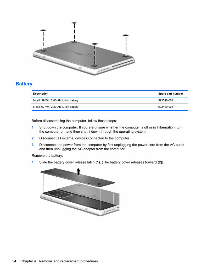
1. Slide the battery cover release latch (1). (The battery cover releases forward (2)).
34 Chapter 4 Removal and replacement procedures
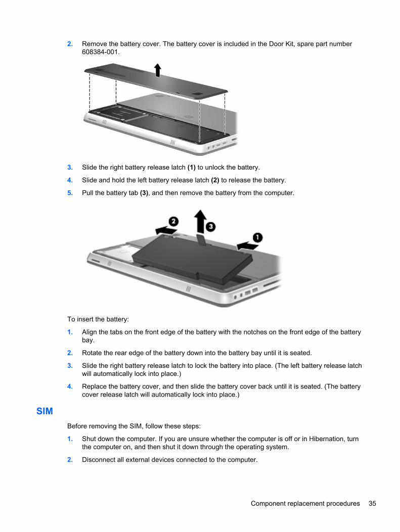
2. Remove the battery cover. The battery cover is included in the Door Kit, spare part number608384-001.
3. Slide the right battery release latch (1) to unlock the battery.
4. Slide and hold the left battery release latch (2) to release the battery.
5. Pull the battery tab (3), and then remove the battery from the computer.
To insert the battery:
1. Align the tabs on the front edge of the battery with the notches on the front edge of the batterybay.
2. Rotate the rear edge of the battery down into the battery bay until it is seated.
3. Slide the right battery release latch to lock the battery into place. (The left battery release latchwill automatically lock into place.)
4. Replace the battery cover, and then slide the battery cover back until it is seated. (The batterycover release latch will automatically lock into place.)
SIM
Before removing the SIM, follow these steps:
1. Shut down the computer. If you are unsure whether the computer is off or in Hibernation, turnthe computer on, and then shut it down through the operating system.
2. Disconnect all external devices connected to the computer.
Component replacement procedures 35
3. Disconnect the power from the computer by first unplugging the power cord from the AC outletand then unplugging the AC adapter from the computer.
4. Remove the battery cover and battery (see Battery on page 34).
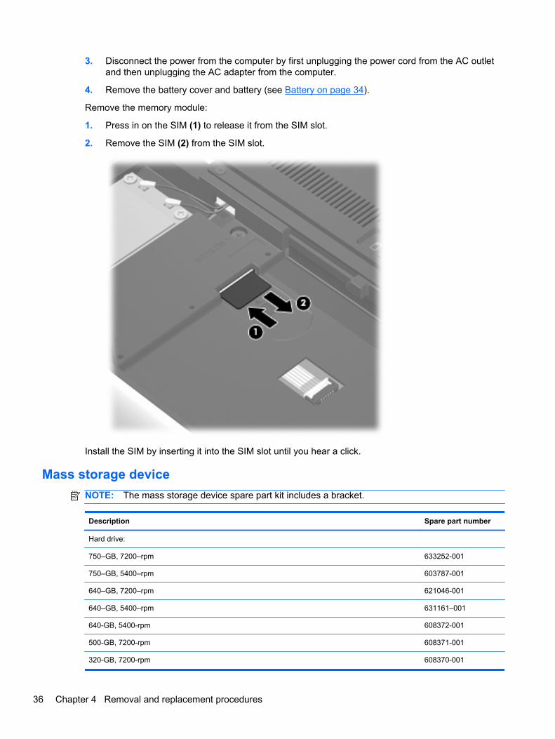
Remove the memory module:
1. Press in on the SIM (1) to release it from the SIM slot.
2. Remove the SIM (2) from the SIM slot.
Install the SIM by inserting it into the SIM slot until you hear a click.
Mass storage device
NOTE: The mass storage device spare part kit includes a bracket.
Description Spare part number
Hard drive:
750–GB, 7200–rpm 633252-001
750–GB, 5400–rpm 603787-001
640–GB, 7200–rpm 621046-001
640–GB, 5400–rpm 631161–001
640-GB, 5400-rpm 608372-001
500-GB, 7200-rpm 608371-001
320-GB, 7200-rpm 608370-001
36 Chapter 4 Removal and replacement procedures
Description Spare part number
250-GB, 7200-rpm 608369-001
Hard Drive Hardware Kit (includes hard drive bracket and screws) 608373-001
Solid-state drive:
256-GB 608368-001
160-GB 608367-001
Before removing the mass storage device, follow these steps:
1. Shut down the computer. If you are unsure whether the computer is off or in Hibernation, turnthe computer on, and then shut it down through the operating system.
2. Disconnect all external devices connected to the computer.
3. Disconnect the power from the computer by first unplugging the power cord from the AC outletand then unplugging the AC adapter from the computer.
4. Remove the battery cover and battery (see Battery on page 34).
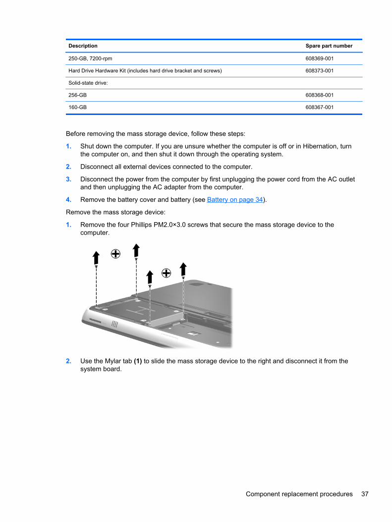
Remove the mass storage device:
1. Remove the four Phillips PM2.0×3.0 screws that secure the mass storage device to thecomputer.
2. Use the Mylar tab (1) to slide the mass storage device to the right and disconnect it from thesystem board.
Component replacement procedures 37
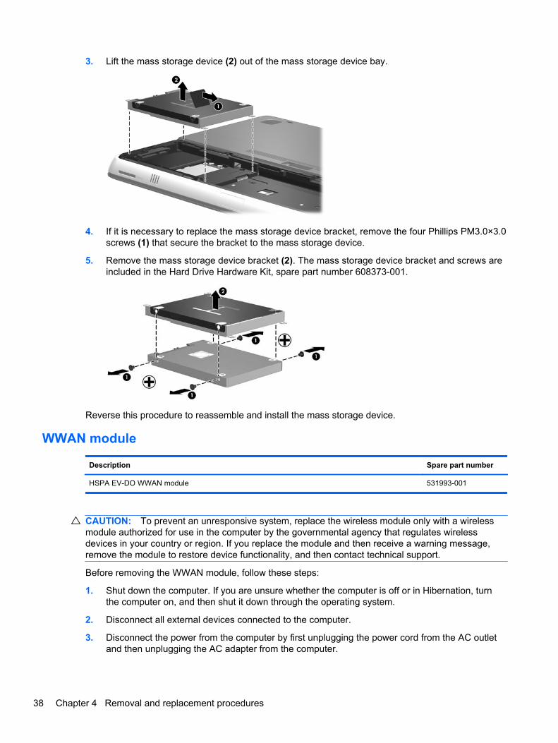
3. Lift the mass storage device (2) out of the mass storage device bay.
4. If it is necessary to replace the mass storage device bracket, remove the four Phillips PM3.0×3.0screws (1) that secure the bracket to the mass storage device.
5. Remove the mass storage device bracket (2). The mass storage device bracket and screws areincluded in the Hard Drive Hardware Kit, spare part number 608373-001.
Reverse this procedure to reassemble and install the mass storage device.
WWAN module
Description Spare part number
HSPA EV-DO WWAN module 531993-001
CAUTION: To prevent an unresponsive system, replace the wireless module only with a wirelessmodule authorized for use in the computer by the governmental agency that regulates wirelessdevices in your country or region. If you replace the module and then receive a warning message,remove the module to restore device functionality, and then contact technical support.
Before removing the WWAN module, follow these steps:
1. Shut down the computer. If you are unsure whether the computer is off or in Hibernation, turnthe computer on, and then shut it down through the operating system.
2. Disconnect all external devices connected to the computer.
3. Disconnect the power from the computer by first unplugging the power cord from the AC outletand then unplugging the AC adapter from the computer.
38 Chapter 4 Removal and replacement procedures
4. Remove the battery cover and battery (see Battery on page 34).
5. Remove the hard drive (see Mass storage device on page 36).
Remove the WWAN module:
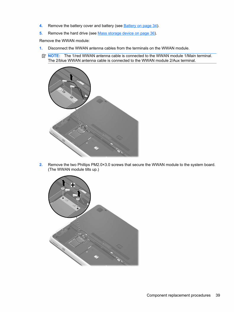
1. Disconnect the WWAN antenna cables from the terminals on the WWAN module.
NOTE: The 1/red WWAN antenna cable is connected to the WWAN module 1/Main terminal.The 2/blue WWAN antenna cable is connected to the WWAN module 2/Aux terminal.
2. Remove the two Phillips PM2.0×3.0 screws that secure the WWAN module to the system board.(The WWAN module tilts up.)
Component replacement procedures 39
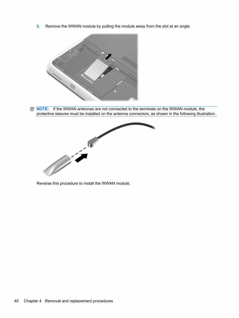
3. Remove the WWAN module by pulling the module away from the slot at an angle.
NOTE: If the WWAN antennas are not connected to the terminals on the WWAN module, theprotective sleeves must be installed on the antenna connectors, as shown in the following illustration.
Reverse this procedure to install the WWAN module.
40 Chapter 4 Removal and replacement procedures
WLAN module
Description Spare part number
Broadcom 43224 802.11a/b/g/n 2×2 WiFi Adapter for use in Antigua and Barbuda, Barbados,Belize, Canada, the Cayman Islands, Guam, Puerto Rico, Trinidad and Tobago,the U.S. Virgin Islands, and the United States
582564-001
Broadcom 43224 802.11a/b/g/n 2×2 WiFi Adapter for use in Afghanistan, Albania, Algeria, Andorra,Angola, Argentina, Armenia, Aruba, Australia, Austria, Azerbaijan, the Bahamas, Bahrain,Bangladesh, Barbados, Belarus, Belgium, Belize, Benin, Bermuda, Bhutan, Bolivia,Bosnia and Herzegovina, Botswana, Brazil, the British Virgin Islands, Brunei, Bulgaria,Burkina Faso, Burundi, Cambodia, Cameroon, Cape Verde, the Central African Republic, Chad,Chile, Colombia, Comoros, the Congo, Costa Rica, Croatia, Cyprus, the Czech Republic, Denmark,Djibouti, Dominica, the Dominican Republic, East Timor, Ecuador, Egypt, El Salvador,Equatorial Guinea, Eritrea, Estonia, Ethiopia, Fiji, Finland, France, French Guiana, Gabon, Gambia,Georgia, Germany, Ghana, Gibraltar, Greece, Grenada, Guadeloupe, Guatemala, Guinea, Guinea-Bissau, Guyana, Haiti, Honduras, Hong Kong, Hungary, Iceland, India, Indonesia, Ireland, Italy,the Ivory Coast, Jamaica, Japan, Jordan, Kazakhstan, Kenya, Kiribati, Kuwait, Kyrgyzstan, Laos,Latvia, Lebanon, Lesotho, Liberia, Liechtenstein, Lithuania, Luxembourg, Macedonia, Madagascar,Malawi, Malaysia, the Maldives, Mali, Malta, the Marshall Islands, Martinique, Mauritania, Mauritius,Mexico, Micronesia, Monaco, Mongolia, Montenegro, Morocco, Mozambique, Namibia, Nauru,Nepal, the Nether Antilles, the Netherlands, New Zealand, Nicaragua, Niger, Nigeria, Norway,Oman, Pakistan, Palau, Panama, Papua New Guinea, Paraguay, the People’s Republic of China,Peru, the Philippines, Poland, Portugal, Qatar, the Republic of Moldova, Romania, Russia,Rwanda, Samoa, San Marino, Sao Tome and Principe, Saudi Arabia, Senegal, Serbia,the Seychelles, Sierra Leone, Singapore, Slovakia, Slovenia, the Solomon Islands, Somalia,South Africa, South Korea, Spain, Sri Lanka, St. Kitts and Nevis, St. Lucia, St. Vincent, Suriname,Swaziland, Sweden, Switzerland, Taiwan, Tajikistan, Tanzania, Thailand, Togo, Tonga, Tunisia,Turkey, Turkmenistan, Tuvalu, Uganda, Ukraine, the United Arab Emirates, the United Kingdom,Uruguay, Uzbekistan, Vanuatu, Venezuela, Vietnam, Yemen, Zaire, Zambia, and Zimbabwe
582564-002
Intel Centrino Advanced-N 6200 802.11a/b/g/n 2×2 WLAN module 572509-001
Intel Centrino Advanced-N 6200 802.11a/b/g 2x2 WLAN module 572510-001
CAUTION: To prevent an unresponsive system, replace the wireless module only with a wirelessmodule authorized for use in the computer by the governmental agency that regulates wirelessdevices in your country or region. If you replace the module and then receive a warning message,remove the module to restore device functionality, and then contact technical support.
Before removing the WLAN module, follow these steps:
1. Shut down the computer. If you are unsure whether the computer is off or in Hibernation, turnthe computer on, and then shut it down through the operating system.
2. Disconnect all external devices connected to the computer.
3. Disconnect the power from the computer by first unplugging the power cord from the AC outletand then unplugging the AC adapter from the computer.
4. Remove the battery cover and battery (see Battery on page 34).
Remove the WLAN module:
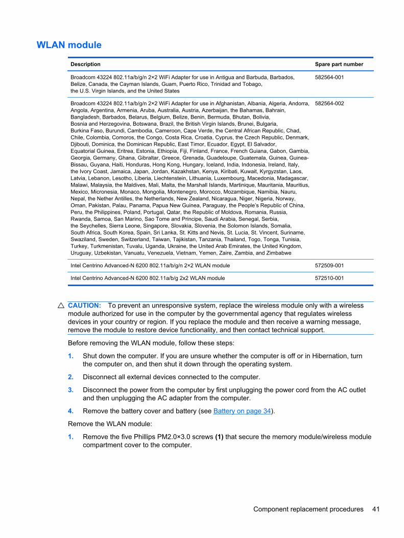
1. Remove the five Phillips PM2.0×3.0 screws (1) that secure the memory module/wireless modulecompartment cover to the computer.
Component replacement procedures 41
2. Slide the memory module/wireless module compartment cover (2) toward the back of thecomputer until the tabs on the cover disengage from the slots in the base enclosure.
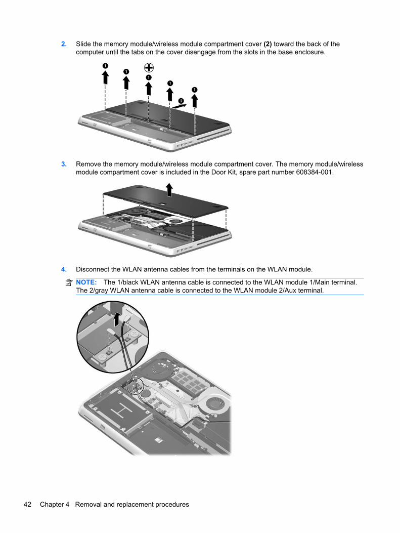
3. Remove the memory module/wireless module compartment cover. The memory module/wirelessmodule compartment cover is included in the Door Kit, spare part number 608384-001.
4. Disconnect the WLAN antenna cables from the terminals on the WLAN module.
NOTE: The 1/black WLAN antenna cable is connected to the WLAN module 1/Main terminal.The 2/gray WLAN antenna cable is connected to the WLAN module 2/Aux terminal.
42 Chapter 4 Removal and replacement procedures
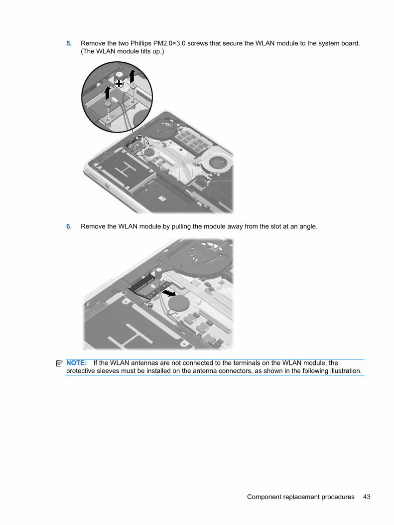
5. Remove the two Phillips PM2.0×3.0 screws that secure the WLAN module to the system board.(The WLAN module tilts up.)
6. Remove the WLAN module by pulling the module away from the slot at an angle.
NOTE: If the WLAN antennas are not connected to the terminals on the WLAN module, theprotective sleeves must be installed on the antenna connectors, as shown in the following illustration.
Component replacement procedures 43
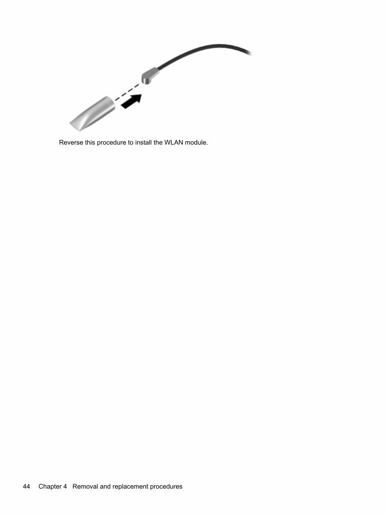
Reverse this procedure to install the WLAN module.
44 Chapter 4 Removal and replacement procedures
RTC battery
Description Spare part number
RTC battery 581926-001
Before removing the RTC battery, follow these steps:
1. Shut down the computer. If you are unsure whether the computer is off or in Hibernation, turnthe computer on, and then shut it down through the operating system.
2. Disconnect all external devices connected to the computer.
3. Disconnect the power from the computer by first unplugging the power cord from the AC outletand then unplugging the AC adapter from the computer.
4. Remove the battery cover and battery (see Battery on page 34).
5. Remove the memory module/wireless module compartment cover (see WLAN moduleon page 41).
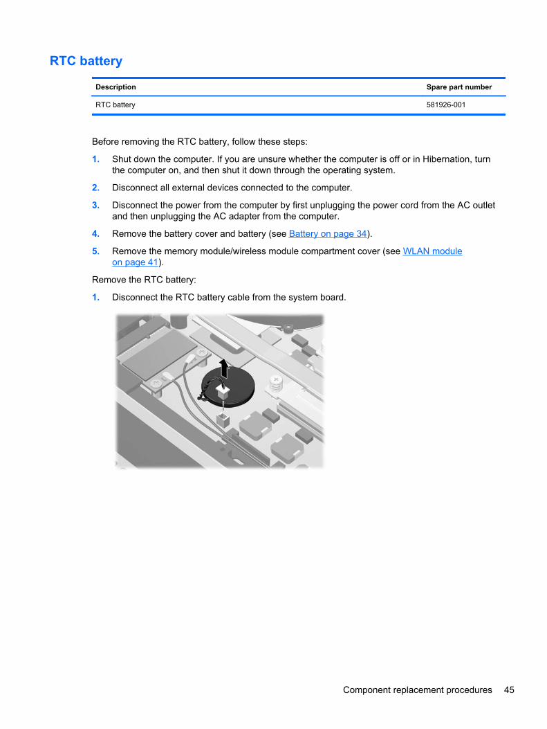
Remove the RTC battery:
1. Disconnect the RTC battery cable from the system board.
Component replacement procedures 45
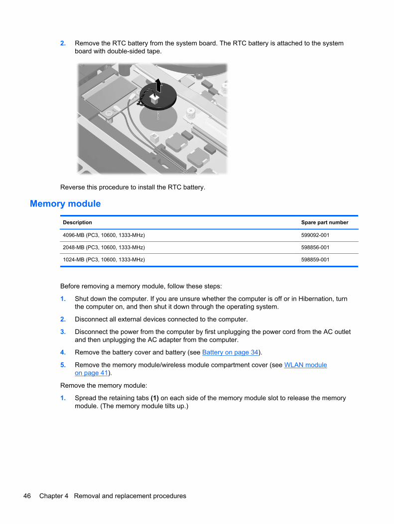
2. Remove the RTC battery from the system board. The RTC battery is attached to the systemboard with double-sided tape.
Reverse this procedure to install the RTC battery.
Memory module
Description Spare part number
4096-MB (PC3, 10600, 1333-MHz) 599092-001
2048-MB (PC3, 10600, 1333-MHz) 598856-001
1024-MB (PC3, 10600, 1333-MHz) 598859-001
Before removing a memory module, follow these steps:
1. Shut down the computer. If you are unsure whether the computer is off or in Hibernation, turnthe computer on, and then shut it down through the operating system.
2. Disconnect all external devices connected to the computer.
3. Disconnect the power from the computer by first unplugging the power cord from the AC outletand then unplugging the AC adapter from the computer.
4. Remove the battery cover and battery (see Battery on page 34).
5. Remove the memory module/wireless module compartment cover (see WLAN moduleon page 41).
Remove the memory module:
1. Spread the retaining tabs (1) on each side of the memory module slot to release the memorymodule. (The memory module tilts up.)
46 Chapter 4 Removal and replacement procedures
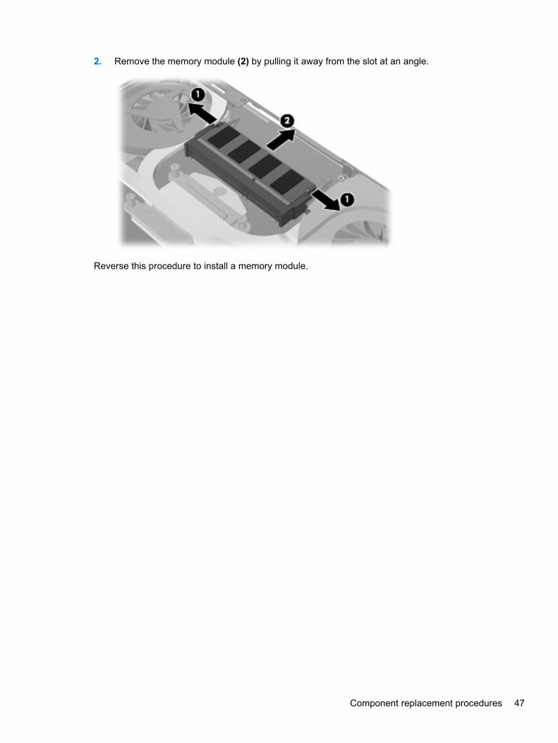
2. Remove the memory module (2) by pulling it away from the slot at an angle.
Reverse this procedure to install a memory module.
Component replacement procedures 47
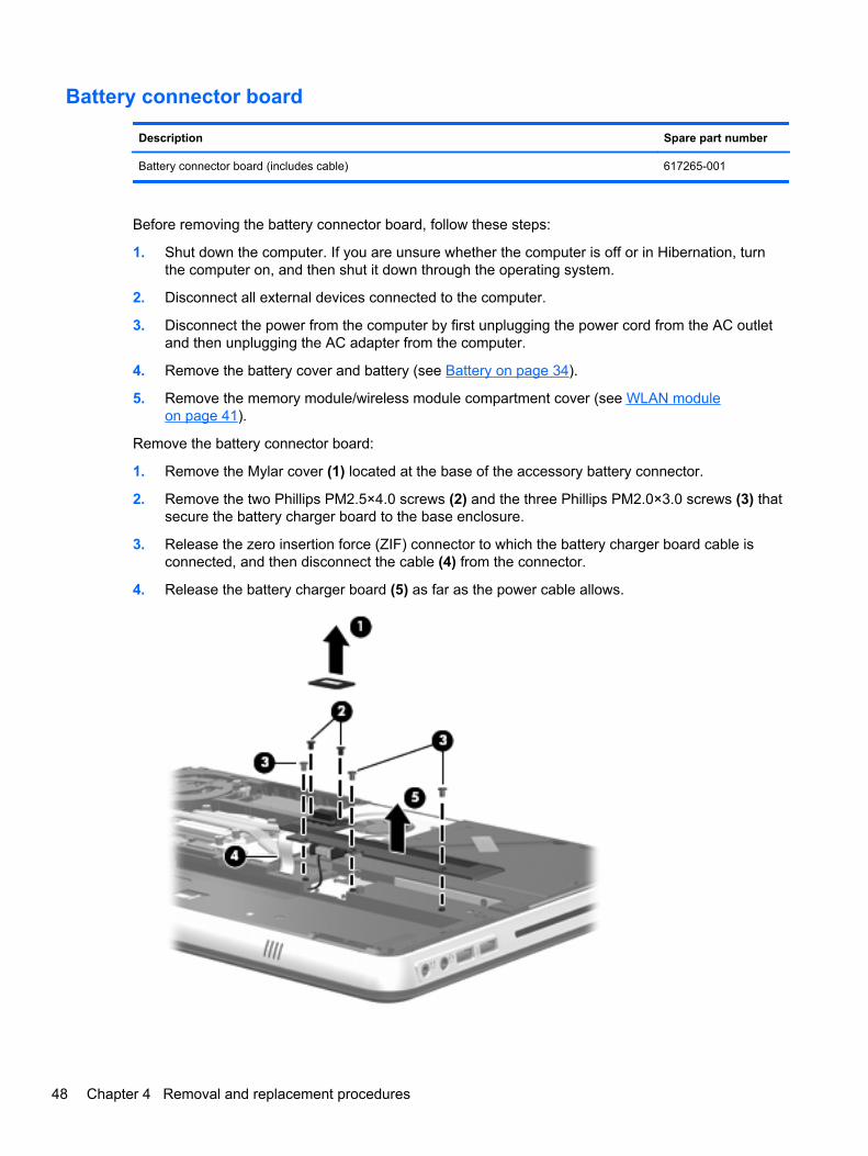
Battery connector board
Description Spare part number
Battery connector board (includes cable) 617265-001
Before removing the battery connector board, follow these steps:
1. Shut down the computer. If you are unsure whether the computer is off or in Hibernation, turnthe computer on, and then shut it down through the operating system.
2. Disconnect all external devices connected to the computer.
3. Disconnect the power from the computer by first unplugging the power cord from the AC outletand then unplugging the AC adapter from the computer.
4. Remove the battery cover and battery (see Battery on page 34).
5. Remove the memory module/wireless module compartment cover (see WLAN moduleon page 41).
Remove the battery connector board:
1. Remove the Mylar cover (1) located at the base of the accessory battery connector.
2. Remove the two Phillips PM2.5×4.0 screws (2) and the three Phillips PM2.0×3.0 screws (3) thatsecure the battery charger board to the base enclosure.
3. Release the zero insertion force (ZIF) connector to which the battery charger board cable isconnected, and then disconnect the cable (4) from the connector.
4. Release the battery charger board (5) as far as the power cable allows.
48 Chapter 4 Removal and replacement procedures
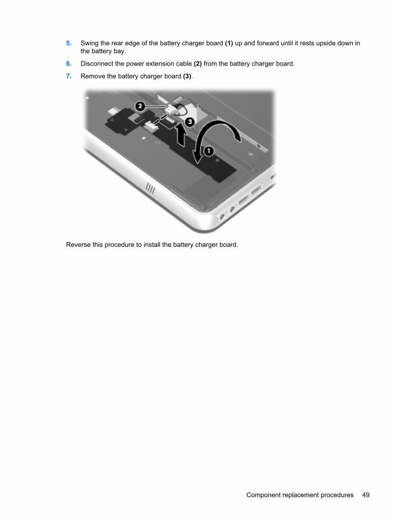
5. Swing the rear edge of the battery charger board (1) up and forward until it rests upside down inthe battery bay.
6. Disconnect the power extension cable (2) from the battery charger board.
7. Remove the battery charger board (3).
Reverse this procedure to install the battery charger board.
Component replacement procedures 49
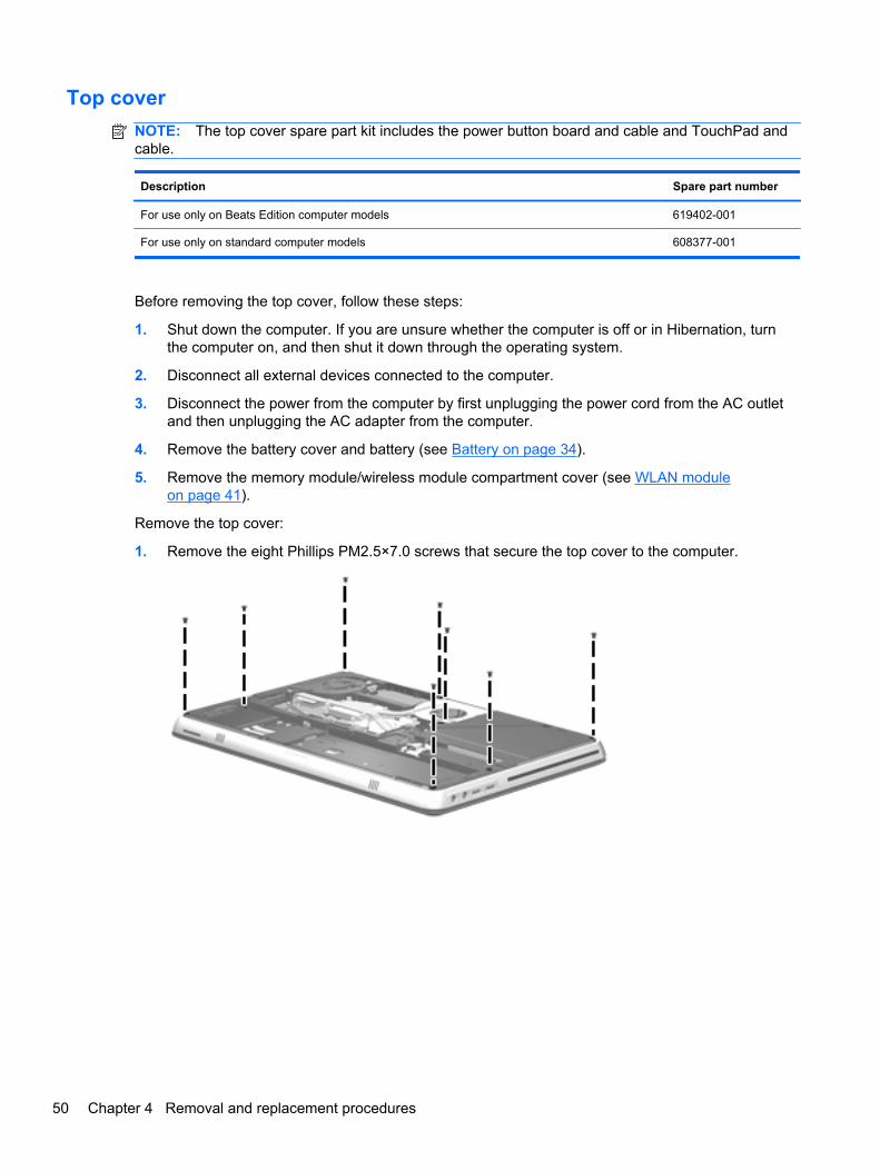
Top cover
NOTE: The top cover spare part kit includes the power button board and cable and TouchPad andcable.
Description Spare part number
For use only on Beats Edition computer models 619402-001
For use only on standard computer models 608377-001
Before removing the top cover, follow these steps:
1. Shut down the computer. If you are unsure whether the computer is off or in Hibernation, turnthe computer on, and then shut it down through the operating system.
2. Disconnect all external devices connected to the computer.
3. Disconnect the power from the computer by first unplugging the power cord from the AC outletand then unplugging the AC adapter from the computer.
4. Remove the battery cover and battery (see Battery on page 34).
5. Remove the memory module/wireless module compartment cover (see WLAN moduleon page 41).
Remove the top cover:
1. Remove the eight Phillips PM2.5×7.0 screws that secure the top cover to the computer.
50 Chapter 4 Removal and replacement procedures
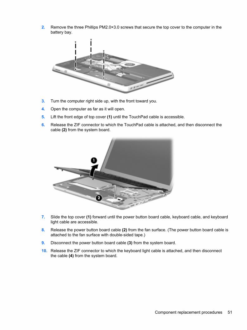
2. Remove the three Phillips PM2.0×3.0 screws that secure the top cover to the computer in thebattery bay.
3. Turn the computer right side up, with the front toward you.
4. Open the computer as far as it will open.
5. Lift the front edge of top cover (1) until the TouchPad cable is accessible.
6. Release the ZIF connector to which the TouchPad cable is attached, and then disconnect thecable (2) from the system board.
7. Slide the top cover (1) forward until the power button board cable, keyboard cable, and keyboardlight cable are accessible.
8. Release the power button board cable (2) from the fan surface. (The power button board cable isattached to the fan surface with double-sided tape.)
9. Disconnect the power button board cable (3) from the system board.
10. Release the ZIF connector to which the keyboard light cable is attached, and then disconnectthe cable (4) from the system board.
Component replacement procedures 51
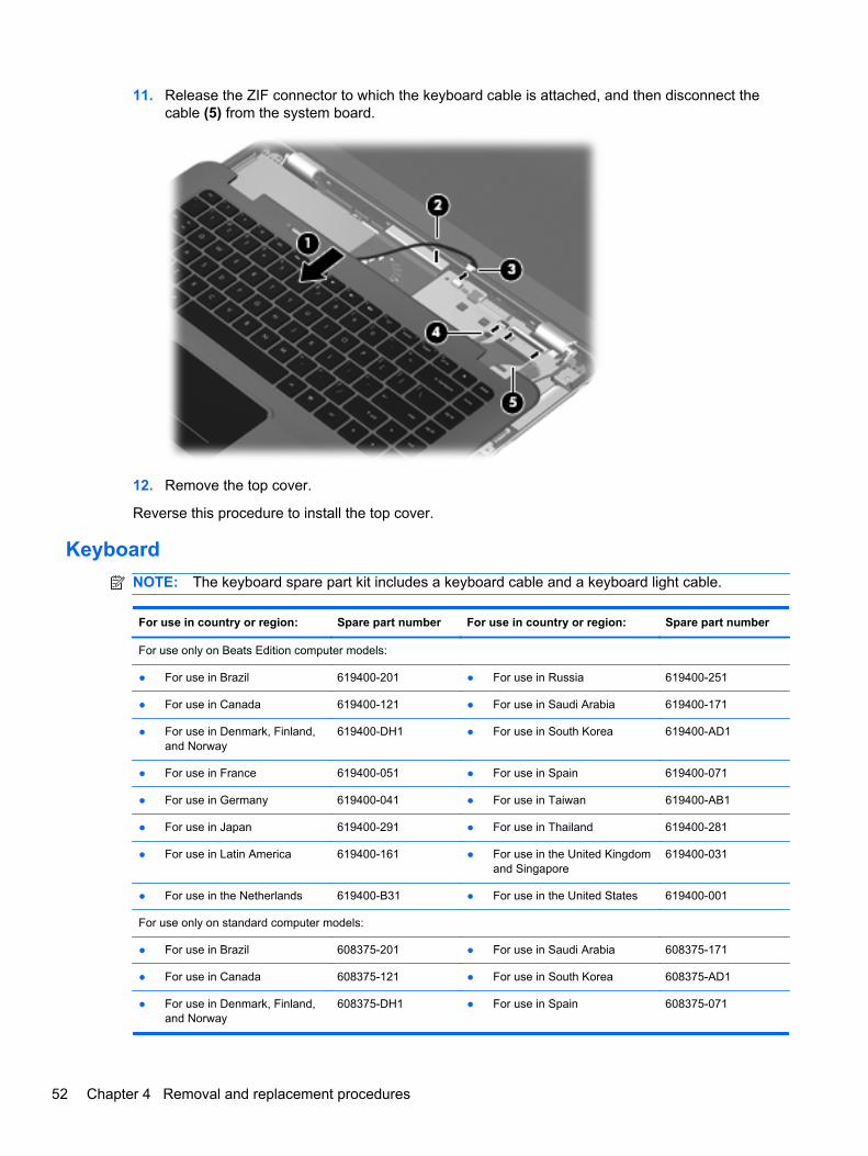
11. Release the ZIF connector to which the keyboard cable is attached, and then disconnect thecable (5) from the system board.
12. Remove the top cover.
Reverse this procedure to install the top cover.
Keyboard
NOTE: The keyboard spare part kit includes a keyboard cable and a keyboard light cable.
For use in country or region: Spare part number For use in country or region: Spare part number
For use only on Beats Edition computer models:
● For use in Brazil 619400-201 ● For use in Russia 619400-251
● For use in Canada 619400-121 ● For use in Saudi Arabia 619400-171
● For use in Denmark, Finland,and Norway
619400-DH1 ● For use in South Korea 619400-AD1
● For use in France 619400-051 ● For use in Spain 619400-071
● For use in Germany 619400-041 ● For use in Taiwan 619400-AB1
● For use in Japan 619400-291 ● For use in Thailand 619400-281
● For use in Latin America 619400-161 ● For use in the United Kingdomand Singapore
619400-031
● For use in the Netherlands 619400-B31 ● For use in the United States 619400-001
For use only on standard computer models:
● For use in Brazil 608375-201 ● For use in Saudi Arabia 608375-171
● For use in Canada 608375-121 ● For use in South Korea 608375-AD1
● For use in Denmark, Finland,and Norway
608375-DH1 ● For use in Spain 608375-071
52 Chapter 4 Removal and replacement procedures
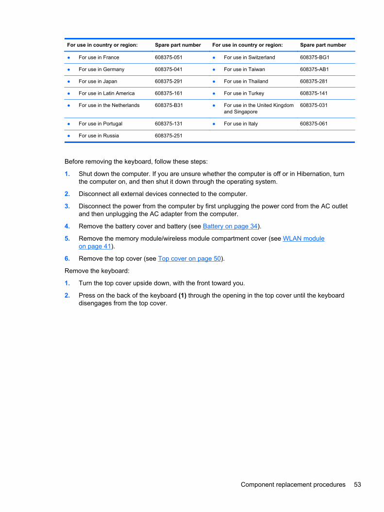
For use in country or region: Spare part number For use in country or region: Spare part number
● For use in France 608375-051 ● For use in Switzerland 608375-BG1
● For use in Germany 608375-041 ● For use in Taiwan 608375-AB1
● For use in Japan 608375-291 ● For use in Thailand 608375-281
● For use in Latin America 608375-161 ● For use in Turkey 608375-141
● For use in the Netherlands 608375-B31 ● For use in the United Kingdomand Singapore
608375-031
● For use in Portugal 608375-131 ● For use in Italy 608375-061
● For use in Russia 608375-251
Before removing the keyboard, follow these steps:
1. Shut down the computer. If you are unsure whether the computer is off or in Hibernation, turnthe computer on, and then shut it down through the operating system.
2. Disconnect all external devices connected to the computer.
3. Disconnect the power from the computer by first unplugging the power cord from the AC outletand then unplugging the AC adapter from the computer.
4. Remove the battery cover and battery (see Battery on page 34).
5. Remove the memory module/wireless module compartment cover (see WLAN moduleon page 41).
6. Remove the top cover (see Top cover on page 50).
Remove the keyboard:
1. Turn the top cover upside down, with the front toward you.
2. Press on the back of the keyboard (1) through the opening in the top cover until the keyboarddisengages from the top cover.
Component replacement procedures 53
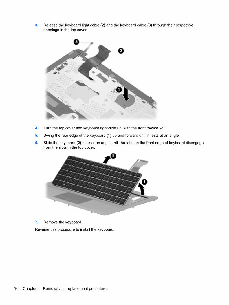
3. Release the keyboard light cable (2) and the keyboard cable (3) through their respectiveopenings in the top cover.
4. Turn the top cover and keyboard right-side up, with the front toward you.
5. Swing the rear edge of the keyboard (1) up and forward until it rests at an angle.
6. Slide the keyboard (2) back at an angle until the tabs on the front edge of keyboard disengagefrom the slots in the top cover.
7. Remove the keyboard.
Reverse this procedure to install the keyboard.
54 Chapter 4 Removal and replacement procedures

Audio/USB board
Description Spare part number
Audio/USB board (includes cable) 608379-001
Before removing the audio/USB board, follow these steps:
1. Shut down the computer. If you are unsure whether the computer is off or in Hibernation, turnthe computer on, and then shut it down through the operating system.
2. Disconnect all external devices connected to the computer.
3. Disconnect the power from the computer by first unplugging the power cord from the AC outletand then unplugging the AC adapter from the computer.
4. Remove the battery cover and battery (see Battery on page 34).
5. Remove the memory module/wireless module compartment cover (see WLAN moduleon page 41).
6. Remove the top cover (see Top cover on page 50).
Remove the audio/USB board:
1. Disconnect the speaker cable (1) from the audio/USB board.
2. Release the grounding tape (2) that secures the audio/USB board cable to the base enclosure.
3. Release the ZIF connector to which the audio/USB board cable is attached, and then disconnectthe cable (3) from the system board.
4. Remove the Phillips PM2.5×4.0 screw (4) that secures the audio/USB board to the baseenclosure.
5. Remove the audio/USB board (5) and cable.
Reverse this procedure to install the audio/USB board and cable.
Component replacement procedures 55
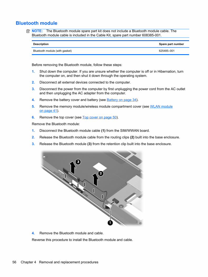
Bluetooth module
NOTE: The Bluetooth module spare part kit does not include a Bluetooth module cable. TheBluetooth module cable is included in the Cable Kit, spare part number 608385-001.
Description Spare part number
Bluetooth module (with gasket) 625485–001
Before removing the Bluetooth module, follow these steps:
1. Shut down the computer. If you are unsure whether the computer is off or in Hibernation, turnthe computer on, and then shut it down through the operating system.
2. Disconnect all external devices connected to the computer.
3. Disconnect the power from the computer by first unplugging the power cord from the AC outletand then unplugging the AC adapter from the computer.
4. Remove the battery cover and battery (see Battery on page 34).
5. Remove the memory module/wireless module compartment cover (see WLAN moduleon page 41).
6. Remove the top cover (see Top cover on page 50).
Remove the Bluetooth module:
1. Disconnect the Bluetooth module cable (1) from the SIM/WWAN board.
2. Release the Bluetooth module cable from the routing clips (2) built into the base enclosure.
3. Release the Bluetooth module (3) from the retention clip built into the base enclosure.
4. Remove the Bluetooth module and cable.
Reverse this procedure to install the Bluetooth module and cable.
56 Chapter 4 Removal and replacement procedures
SIM/WWAN board
Description Spare part number
SIM/WWAN board (includes cable) 608382-001
Before removing the SIM/WWAN board, follow these steps:
1. Shut down the computer. If you are unsure whether the computer is off or in Hibernation, turnthe computer on, and then shut it down through the operating system.
2. Disconnect all external devices connected to the computer.
3. Disconnect the power from the computer by first unplugging the power cord from the AC outletand then unplugging the AC adapter from the computer.
4. Remove the battery cover and battery (see Battery on page 34), and then remove the followingcomponents:
a. SIM (see SIM on page 35)
b. Hard drive (see Mass storage device on page 36)
c. WWAN module (see WWAN module on page 38)
d. Memory module/wireless module compartment cover (see WLAN module on page 41)
e. Top cover (see Top cover on page 50)
Remove the SIM/WWAN board:
1. Disconnect the Bluetooth module cable (1) from the SIM/WWAN board.
2. Release the grounding tape (2) that secures the SIM/WWAN cable to the base enclosure.
3. Release the ZIF connector to which the SIM/WWAN board cable is attached, and thendisconnect the cable (3) from the system board.
4. Remove the Phillips PM2.0×3.0 screw (4) that secures the SIM/WWAN board to the baseenclosure.
Component replacement procedures 57
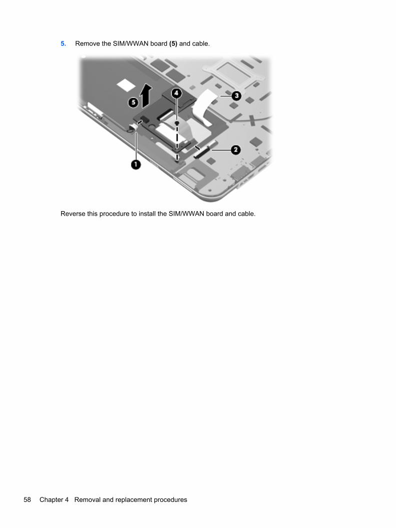
5. Remove the SIM/WWAN board (5) and cable.
Reverse this procedure to install the SIM/WWAN board and cable.
58 Chapter 4 Removal and replacement procedures
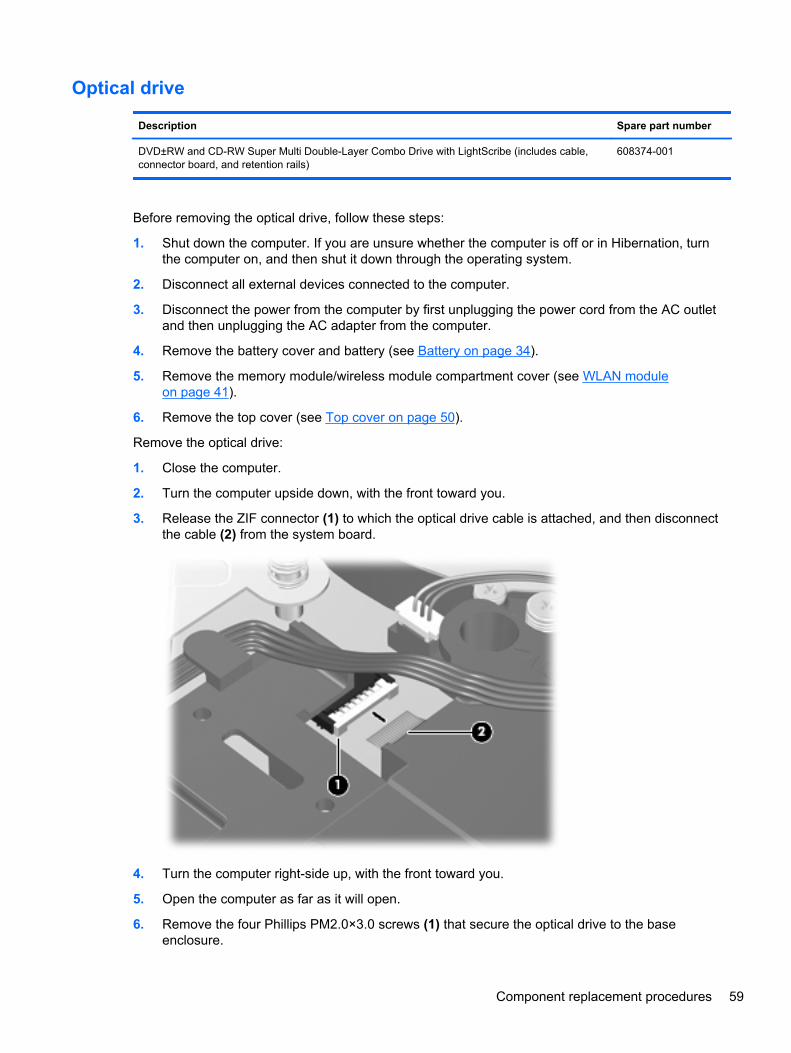
Optical drive
Description Spare part number
DVD±RW and CD-RW Super Multi Double-Layer Combo Drive with LightScribe (includes cable,connector board, and retention rails)
608374-001
Before removing the optical drive, follow these steps:
1. Shut down the computer. If you are unsure whether the computer is off or in Hibernation, turnthe computer on, and then shut it down through the operating system.
2. Disconnect all external devices connected to the computer.
3. Disconnect the power from the computer by first unplugging the power cord from the AC outletand then unplugging the AC adapter from the computer.
4. Remove the battery cover and battery (see Battery on page 34).
5. Remove the memory module/wireless module compartment cover (see WLAN moduleon page 41).
6. Remove the top cover (see Top cover on page 50).
Remove the optical drive:
1. Close the computer.
2. Turn the computer upside down, with the front toward you.
3. Release the ZIF connector (1) to which the optical drive cable is attached, and then disconnectthe cable (2) from the system board.
4. Turn the computer right-side up, with the front toward you.
5. Open the computer as far as it will open.
6. Remove the four Phillips PM2.0×3.0 screws (1) that secure the optical drive to the baseenclosure.
Component replacement procedures 59
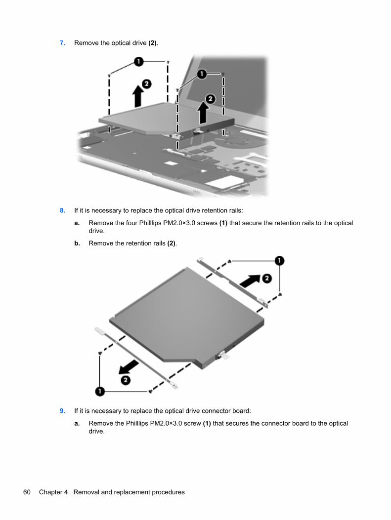
7. Remove the optical drive (2).
8. If it is necessary to replace the optical drive retention rails:
a. Remove the four Philllips PM2.0×3.0 screws (1) that secure the retention rails to the opticaldrive.
b. Remove the retention rails (2).
9. If it is necessary to replace the optical drive connector board:
a. Remove the Philllips PM2.0×3.0 screw (1) that secures the connector board to the opticaldrive.
60 Chapter 4 Removal and replacement procedures
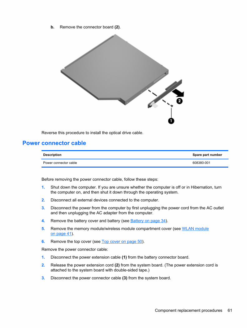
b. Remove the connector board (2).
Reverse this procedure to install the optical drive cable.
Power connector cable
Description Spare part number
Power connector cable 608380-001
Before removing the power connector cable, follow these steps:
1. Shut down the computer. If you are unsure whether the computer is off or in Hibernation, turnthe computer on, and then shut it down through the operating system.
2. Disconnect all external devices connected to the computer.
3. Disconnect the power from the computer by first unplugging the power cord from the AC outletand then unplugging the AC adapter from the computer.
4. Remove the battery cover and battery (see Battery on page 34).
5. Remove the memory module/wireless module compartment cover (see WLAN moduleon page 41).
6. Remove the top cover (see Top cover on page 50).
Remove the power connector cable:
1. Disconnect the power extension cable (1) from the battery connector board.
2. Release the power extension cord (2) from the system board. (The power extension cord isattached to the system board with double-sided tape.)
3. Disconnect the power connector cable (3) from the system board.
Component replacement procedures 61
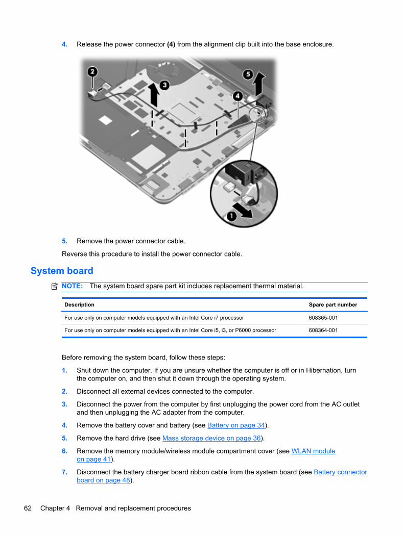
4. Release the power connector (4) from the alignment clip built into the base enclosure.
5. Remove the power connector cable.
Reverse this procedure to install the power connector cable.
System board
NOTE: The system board spare part kit includes replacement thermal material.
Description Spare part number
For use only on computer models equipped with an Intel Core i7 processor 608365-001
For use only on computer models equipped with an Intel Core i5, i3, or P6000 processor 608364-001
Before removing the system board, follow these steps:
1. Shut down the computer. If you are unsure whether the computer is off or in Hibernation, turnthe computer on, and then shut it down through the operating system.
2. Disconnect all external devices connected to the computer.
3. Disconnect the power from the computer by first unplugging the power cord from the AC outletand then unplugging the AC adapter from the computer.
4. Remove the battery cover and battery (see Battery on page 34).
5. Remove the hard drive (see Mass storage device on page 36).
6. Remove the memory module/wireless module compartment cover (see WLAN moduleon page 41).
7. Disconnect the battery charger board ribbon cable from the system board (see Battery connectorboard on page 48).
62 Chapter 4 Removal and replacement procedures
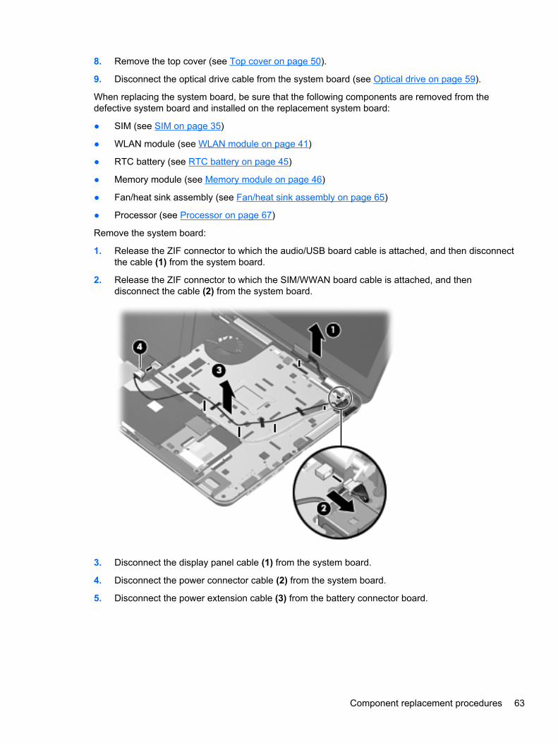
8. Remove the top cover (see Top cover on page 50).
9. Disconnect the optical drive cable from the system board (see Optical drive on page 59).
When replacing the system board, be sure that the following components are removed from thedefective system board and installed on the replacement system board:
● SIM (see SIM on page 35)
● WLAN module (see WLAN module on page 41)
● RTC battery (see RTC battery on page 45)
● Memory module (see Memory module on page 46)
● Fan/heat sink assembly (see Fan/heat sink assembly on page 65)
● Processor (see Processor on page 67)
Remove the system board:
1. Release the ZIF connector to which the audio/USB board cable is attached, and then disconnectthe cable (1) from the system board.
2. Release the ZIF connector to which the SIM/WWAN board cable is attached, and thendisconnect the cable (2) from the system board.
3. Disconnect the display panel cable (1) from the system board.
4. Disconnect the power connector cable (2) from the system board.
5. Disconnect the power extension cable (3) from the battery connector board.
Component replacement procedures 63
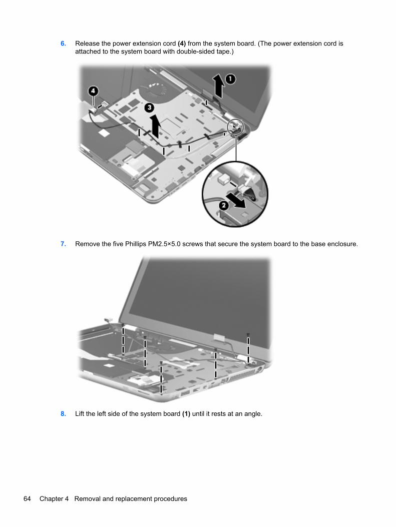
6. Release the power extension cord (4) from the system board. (The power extension cord isattached to the system board with double-sided tape.)
7. Remove the five Phillips PM2.5×5.0 screws that secure the system board to the base enclosure.
8. Lift the left side of the system board (1) until it rests at an angle.
64 Chapter 4 Removal and replacement procedures
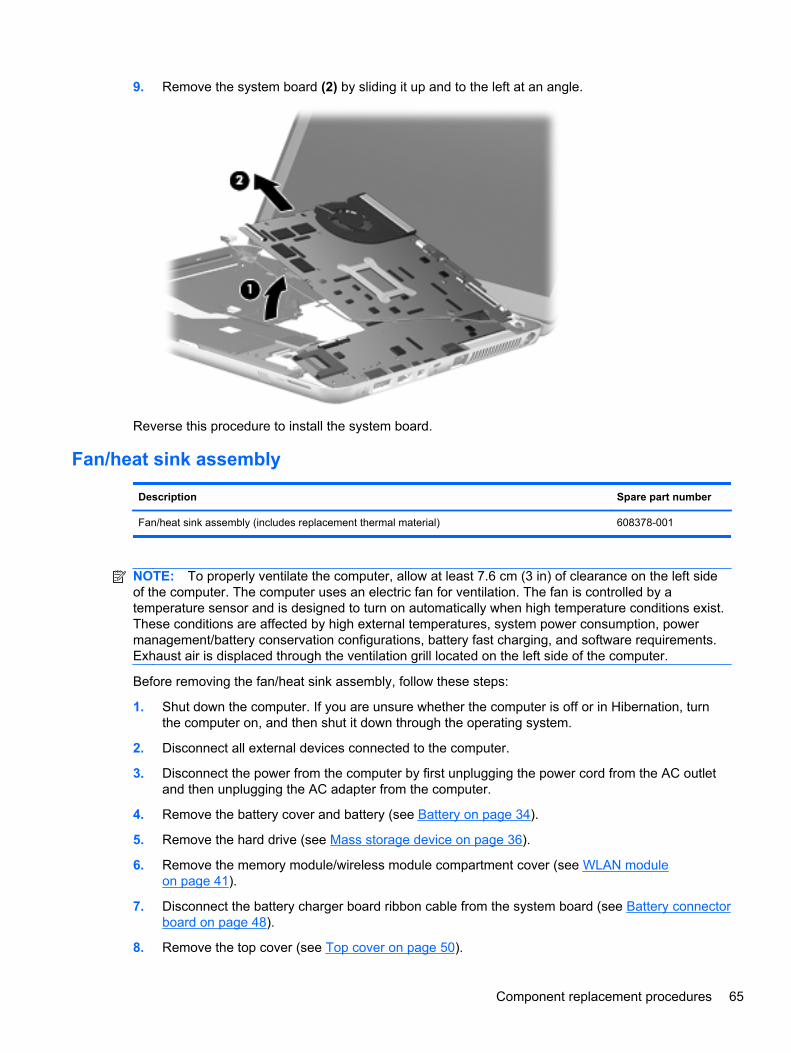
9. Remove the system board (2) by sliding it up and to the left at an angle.
Reverse this procedure to install the system board.
Fan/heat sink assembly
Description Spare part number
Fan/heat sink assembly (includes replacement thermal material) 608378-001
NOTE: To properly ventilate the computer, allow at least 7.6 cm (3 in) of clearance on the left sideof the computer. The computer uses an electric fan for ventilation. The fan is controlled by atemperature sensor and is designed to turn on automatically when high temperature conditions exist.These conditions are affected by high external temperatures, system power consumption, powermanagement/battery conservation configurations, battery fast charging, and software requirements.Exhaust air is displaced through the ventilation grill located on the left side of the computer.
Before removing the fan/heat sink assembly, follow these steps:
1. Shut down the computer. If you are unsure whether the computer is off or in Hibernation, turnthe computer on, and then shut it down through the operating system.
2. Disconnect all external devices connected to the computer.
3. Disconnect the power from the computer by first unplugging the power cord from the AC outletand then unplugging the AC adapter from the computer.
4. Remove the battery cover and battery (see Battery on page 34).
5. Remove the hard drive (see Mass storage device on page 36).
6. Remove the memory module/wireless module compartment cover (see WLAN moduleon page 41).
7. Disconnect the battery charger board ribbon cable from the system board (see Battery connectorboard on page 48).
8. Remove the top cover (see Top cover on page 50).
Component replacement procedures 65
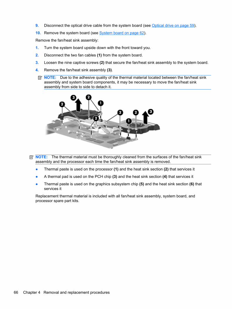
9. Disconnect the optical drive cable from the system board (see Optical drive on page 59).
10. Remove the system board (see System board on page 62).
Remove the fan/heat sink assembly:
1. Turn the system board upside down with the front toward you.
2. Disconnect the two fan cables (1) from the system board.
3. Loosen the nine captive screws (2) that secure the fan/heat sink assembly to the system board.
4. Remove the fan/heat sink assembly (3).
NOTE: Due to the adhesive quality of the thermal material located between the fan/heat sinkassembly and system board components, it may be necessary to move the fan/heat sinkassembly from side to side to detach it.
NOTE: The thermal material must be thoroughly cleaned from the surfaces of the fan/heat sinkassembly and the processor each time the fan/heat sink assembly is removed.
● Thermal paste is used on the processor (1) and the heat sink section (2) that services it
● A thermal pad is used on the PCH chip (3) and the heat sink section (4) that services it
● Thermal paste is used on the graphics subsystem chip (5) and the heat sink section (6) thatservices it
Replacement thermal material is included with all fan/heat sink assembly, system board, andprocessor spare part kits.
66 Chapter 4 Removal and replacement procedures
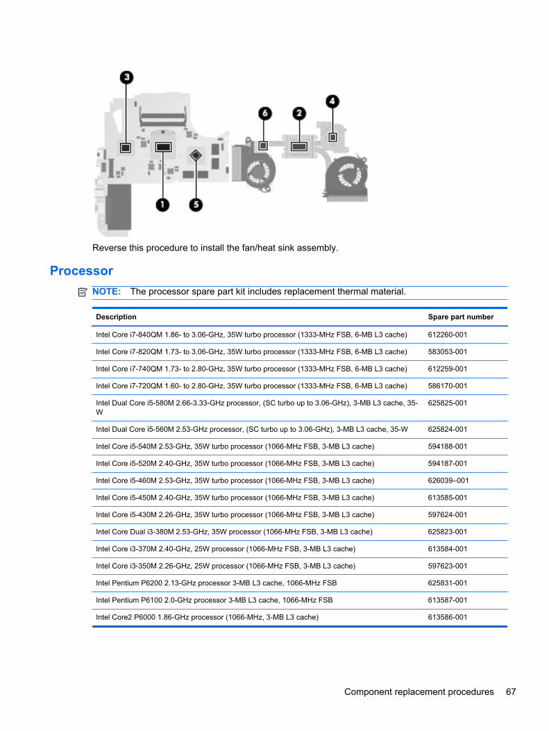
Reverse this procedure to install the fan/heat sink assembly.
Processor
NOTE: The processor spare part kit includes replacement thermal material.
Description Spare part number
Intel Core i7-840QM 1.86- to 3.06-GHz, 35W turbo processor (1333-MHz FSB, 6-MB L3 cache) 612260-001
Intel Core i7-820QM 1.73- to 3.06-GHz, 35W turbo processor (1333-MHz FSB, 6-MB L3 cache) 583053-001
Intel Core i7-740QM 1.73- to 2.80-GHz, 35W turbo processor (1333-MHz FSB, 6-MB L3 cache) 612259-001
Intel Core i7-720QM 1.60- to 2.80-GHz, 35W turbo processor (1333-MHz FSB, 6-MB L3 cache) 586170-001
Intel Dual Core i5-580M 2.66-3.33-GHz processor, (SC turbo up to 3.06-GHz), 3-MB L3 cache, 35-W
625825-001
Intel Dual Core i5-560M 2.53-GHz processor, (SC turbo up to 3.06-GHz), 3-MB L3 cache, 35-W 625824-001
Intel Core i5-540M 2.53-GHz, 35W turbo processor (1066-MHz FSB, 3-MB L3 cache) 594188-001
Intel Core i5-520M 2.40-GHz, 35W turbo processor (1066-MHz FSB, 3-MB L3 cache) 594187-001
Intel Core i5-460M 2.53-GHz, 35W turbo processor (1066-MHz FSB, 3-MB L3 cache) 626039–001
Intel Core i5-450M 2.40-GHz, 35W turbo processor (1066-MHz FSB, 3-MB L3 cache) 613585-001
Intel Core i5-430M 2.26-GHz, 35W turbo processor (1066-MHz FSB, 3-MB L3 cache) 597624-001
Intel Core Dual i3-380M 2.53-GHz, 35W processor (1066-MHz FSB, 3-MB L3 cache) 625823-001
Intel Core i3-370M 2.40-GHz, 25W processor (1066-MHz FSB, 3-MB L3 cache) 613584-001
Intel Core i3-350M 2.26-GHz, 25W processor (1066-MHz FSB, 3-MB L3 cache) 597623-001
Intel Pentium P6200 2.13-GHz processor 3-MB L3 cache, 1066-MHz FSB 625831-001
Intel Pentium P6100 2.0-GHz processor 3-MB L3 cache, 1066-MHz FSB 613587-001
Intel Core2 P6000 1.86-GHz processor (1066-MHz, 3-MB L3 cache) 613586-001
Component replacement procedures 67
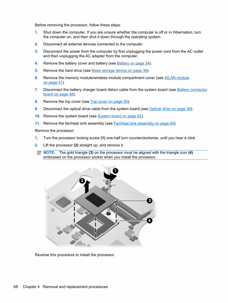
Before removing the processor, follow these steps:
1. Shut down the computer. If you are unsure whether the computer is off or in Hibernation, turnthe computer on, and then shut it down through the operating system.
2. Disconnect all external devices connected to the computer.
3. Disconnect the power from the computer by first unplugging the power cord from the AC outletand then unplugging the AC adapter from the computer.
4. Remove the battery cover and battery (see Battery on page 34).
5. Remove the hard drive (see Mass storage device on page 36).
6. Remove the memory module/wireless module compartment cover (see WLAN moduleon page 41).
7. Disconnect the battery charger board ribbon cable from the system board (see Battery connectorboard on page 48).
8. Remove the top cover (see Top cover on page 50).
9. Disconnect the optical drive cable from the system board (see Optical drive on page 59).
10. Remove the system board (see System board on page 62).
11. Remove the fan/heat sink assembly (see Fan/heat sink assembly on page 65).
Remove the processor:
1. Turn the processor locking screw (1) one-half turn counterclockwise, until you hear a click.
2. Lift the processor (2) straight up, and remove it.
NOTE: The gold triangle (3) on the processor must be aligned with the triangle icon (4)embossed on the processor socket when you install the processor.
Reverse this procedure to install the processor.
68 Chapter 4 Removal and replacement procedures
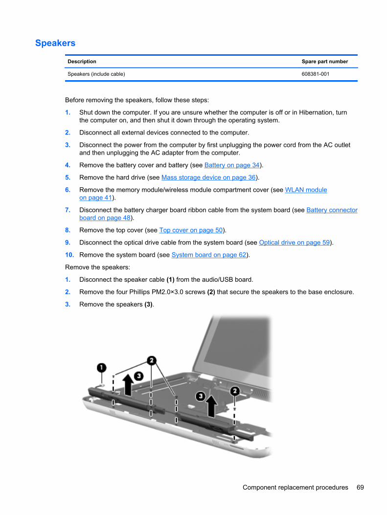
Speakers
Description Spare part number
Speakers (include cable) 608381-001
Before removing the speakers, follow these steps:
1. Shut down the computer. If you are unsure whether the computer is off or in Hibernation, turnthe computer on, and then shut it down through the operating system.
2. Disconnect all external devices connected to the computer.
3. Disconnect the power from the computer by first unplugging the power cord from the AC outletand then unplugging the AC adapter from the computer.
4. Remove the battery cover and battery (see Battery on page 34).
5. Remove the hard drive (see Mass storage device on page 36).
6. Remove the memory module/wireless module compartment cover (see WLAN moduleon page 41).
7. Disconnect the battery charger board ribbon cable from the system board (see Battery connectorboard on page 48).
8. Remove the top cover (see Top cover on page 50).
9. Disconnect the optical drive cable from the system board (see Optical drive on page 59).
10. Remove the system board (see System board on page 62).
Remove the speakers:
1. Disconnect the speaker cable (1) from the audio/USB board.
2. Remove the four Phillips PM2.0×3.0 screws (2) that secure the speakers to the base enclosure.
3. Remove the speakers (3).
Component replacement procedures 69
Reverse this procedure to install the speakers.
Display assembly
NOTE: The display assembly spare part kit includes a display panel cable, webcam/microphonemodule and cable, 2 WLAN antenna cables and transceivers,and 2 WWAN antenna cables andtransceivers.
Description Spare part number
14.5-in, LED, HD, AntiGlare, flush glass SVA display assembly for use only on Beats Editioncomputer models
619399-001
14.5-in, LED, HD, AntiGlare, flush glass SVA display assembly for use only on standard computermodels
616270-001
14.5-in, LED, HD+, AntiGlare, flush glass WVA display assembly for use only on standardcomputer models
608366-001
Before removing the display assembly, follow these steps:
1. Shut down the computer. If you are unsure whether the computer is off or in Hibernation, turnthe computer on, and then shut it down through the operating system.
2. Disconnect all external devices connected to the computer.
3. Disconnect the power from the computer by first unplugging the power cord from the AC outletand then unplugging the AC adapter from the computer.
4. Remove the battery cover and battery (see Battery on page 34).
5. Remove the memory module/wireless module compartment cover (see WLAN moduleon page 41).
6. Remove the top cover (see Top cover on page 50).
Remove the display assembly:
1. Close the computer.
2. Turn the computer upside down, with the front toward you.
3. Disconnect the wireless antenna cables (1) from the WWAN and WLAN modules.
4. Release the wireless antenna cables from the routing clips (2) built into the base enclosure.
5. Release the grounding tape (3) that secures the WWAN antenna cables to the base enclosure.
70 Chapter 4 Removal and replacement procedures
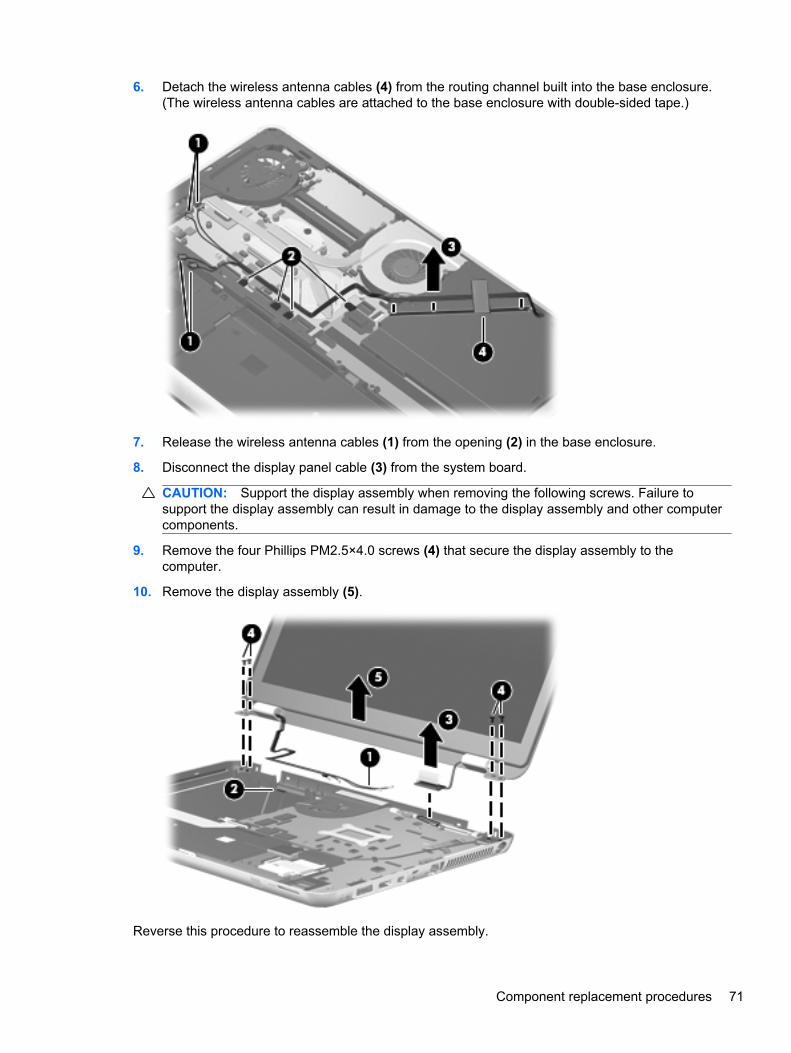
6. Detach the wireless antenna cables (4) from the routing channel built into the base enclosure.(The wireless antenna cables are attached to the base enclosure with double-sided tape.)
7. Release the wireless antenna cables (1) from the opening (2) in the base enclosure.
8. Disconnect the display panel cable (3) from the system board.
CAUTION: Support the display assembly when removing the following screws. Failure tosupport the display assembly can result in damage to the display assembly and other computercomponents.
9. Remove the four Phillips PM2.5×4.0 screws (4) that secure the display assembly to thecomputer.
10. Remove the display assembly (5).
Reverse this procedure to reassemble the display assembly.
Component replacement procedures 71
5 Setup Utility (BIOS)
Setup Utility, or Basic Input/Output System (BIOS), controls communication between all the input andoutput devices on the system (such as disk drives, display, keyboard, mouse, and printer). SetupUtility includes settings for the types of peripherals installed, the startup sequence of the computer,and the amount of system and extended memory.
CAUTION: Use extreme care when making changes in Setup Utility. Errors can prevent thecomputer from operating properly.
Starting Setup UtilityNOTE: The fingerprint reader (select models only) cannot be used to access Setup Utility.
▲ Turn on or restart the computer. While the “Press the ESC key for Startup Menu” message isdisplayed in the lower-left corner of the screen, press esc. When the Startup Menu is displayed,press f10.
Using Setup Utility
Changing the language of Setup Utility
1. Start Setup Utility.
2. Use the arrow keys to select System Configuration > Language, and then press enter.
3. Use the arrow keys to select a language, and then press enter.
4. When a confirmation prompt with your language selected is displayed, press enter.
5. To save your change and exit Setup Utility, use the arrow keys to select Exit > Exit SavingChanges, and then press enter.
Your change takes effect immediately.
Navigating and selecting in Setup Utility
Because Setup Utility is not Windows based, it does not support the TouchPad. Navigation andselection are by keystroke.
● To choose a menu or a menu item, use the arrow keys.
● To choose an item in a list or to toggle a field—for example an Enable/Disable field—use eitherthe arrow keys or f5 and f6.
● To select an item, press enter.
● To close a text box or return to the menu display, press esc.
● To display additional navigation and selection information while Setup Utility is open, press f1.
72 Chapter 5 Setup Utility (BIOS)
Displaying system information
1. Start Setup Utility.
2. Select the Main menu. System information such as the system time and date, and identificationinformation about the computer is displayed.
3. To exit Setup Utility without changing any settings, use the arrow keys to select Exit > ExitDiscarding Changes, and then press enter.
Restoring factory default settings in Setup Utility
1. Start Setup Utility.
2. Use the arrow keys to select Exit > Load Setup Defaults, and then press enter.
3. When the Setup Confirmation is displayed, press enter.
4. To save your change and exit Setup Utility, use the arrow keys to select Exit > Exit SavingChanges, and then press enter.
The Setup Utility factory settings take effect when the computer restarts.
NOTE: Your password, security, and language settings are not changed when you restore thefactory settings.
Using Setup Utility 73
Exiting Setup Utility
● To exit Setup Utility and save your changes from the current session:
If the Setup Utility menus are not visible, press esc to return to the menu display. Then use thearrow keys to select Exit > Exit Saving Changes, and then press enter.
● To exit Setup Utility without saving your changes from the current session:
If the Setup Utility menus are not visible, press esc to return to the menu display. Then use thearrow keys to select Exit > Exit Discarding Changes, and then press enter.
Updating the BIOSUpdated versions of the BIOS may be available on the HP Web site.
Most BIOS updates on the HP Web site are packaged in compressed files called SoftPaqs.
Some download packages contain a file named Readme.txt, which contains information regardinginstalling and troubleshooting the file.
Determining the BIOS version
To determine whether available BIOS updates contain later BIOS versions than those currentlyinstalled on the computer, you need to know the version of the system BIOS currently installed.
BIOS version information (also known as ROM date and System BIOS) can be displayed by pressingfn+esc (if you are already in Windows) or by using Setup Utility.
1. Start Setup Utility.
2. If the system information is not displayed, use the arrow keys to select the Main menu.
BIOS and other system information is displayed.
3. To exit Setup Utility, use the arrow keys to select Exit > Exit Discarding Changes, and thenpress enter.
74 Chapter 5 Setup Utility (BIOS)
Downloading a BIOS update
CAUTION: To reduce the risk of damage to the computer or an unsuccessful installation, downloadand install a BIOS update only when the computer is connected to reliable external power using theAC adapter. Do not download or install a BIOS update while the computer is running on batterypower, docked in an optional docking device, or connected to an optional power source. During thedownload and installation, follow these instructions:
Do not disconnect power from the computer by unplugging the power cord from the AC outlet.
Do not shut down the computer or initiate Sleep or Hibernation.
Do not insert, remove, connect, or disconnect any device, cable, or cord.
1. Access the page on the HP Web site that provides software for your computer:
Windows 7—Select Start > Help and Support > Maintain.
Windows XP—Select Start > Help and Support, and then select the software and driversupdate.
2. Follow the on-screen instructions to identify your computer and access the BIOS update youwant to download.
3. At the download area, follow these steps:
a. Identify the BIOS update that is later than the BIOS version currently installed on yourcomputer. Make a note of the date, name, or other identifier. You may need this informationto locate the update later, after it has been downloaded to your hard drive.
b. Follow the on-screen instructions to download your selection to the hard drive.
Make a note of the path to the location on your hard drive where the BIOS update isdownloaded. You will need to access this path when you are ready to install the update.
NOTE: If you connect your computer to a network, consult the network administrator beforeinstalling any software updates, especially system BIOS updates.
BIOS installation procedures vary. Follow any instructions that are displayed on the screen after thedownload is complete. If no instructions are displayed, follow these steps:
1. Windows 7—Open Windows Explorer by selecting Start > Computer.
Windows XP—Open Windows Explorer by selecting Start > My Computer.
2. Double-click your hard drive designation. The hard drive designation is typically Local Disk (C:).
3. Using the hard drive path you recorded earlier, open the folder on your hard drive that containsthe update.
4. Double-click the file that has an .exe extension (for example, filename.exe).
The BIOS installation begins.
5. Complete the installation by following the on-screen instructions.
NOTE: After a message on the screen reports a successful installation, you can delete thedownloaded file from your hard drive.
Updating the BIOS 75
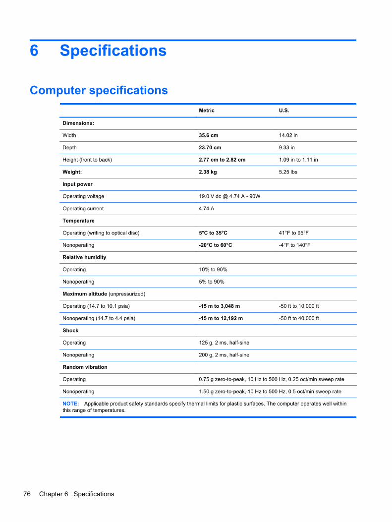
6 Specifications
Computer specifications
Metric U.S.
Dimensions:
Width 35.6 cm 14.02 in
Depth 23.70 cm 9.33 in
Height (front to back) 2.77 cm to 2.82 cm 1.09 in to 1.11 in
Weight: 2.38 kg 5.25 lbs
Input power
Operating voltage 19.0 V dc @ 4.74 A - 90W
Operating current 4.74 A
Temperature
Operating (writing to optical disc) 5°C to 35°C 41°F to 95°F
Nonoperating -20°C to 60°C -4°F to 140°F
Relative humidity
Operating 10% to 90%
Nonoperating 5% to 90%
Maximum altitude (unpressurized)
Operating (14.7 to 10.1 psia) -15 m to 3,048 m -50 ft to 10,000 ft
Nonoperating (14.7 to 4.4 psia) -15 m to 12,192 m -50 ft to 40,000 ft
Shock
Operating 125 g, 2 ms, half-sine
Nonoperating 200 g, 2 ms, half-sine
Random vibration
Operating 0.75 g zero-to-peak, 10 Hz to 500 Hz, 0.25 oct/min sweep rate
Nonoperating 1.50 g zero-to-peak, 10 Hz to 500 Hz, 0.5 oct/min sweep rate
NOTE: Applicable product safety standards specify thermal limits for plastic surfaces. The computer operates well withinthis range of temperatures.
76 Chapter 6 Specifications
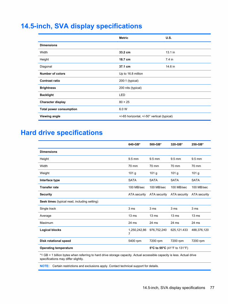
14.5-inch, SVA display specifications
Metric U.S.
Dimensions
Width 33.2 cm 13.1 in
Height 18.7 cm 7.4 in
Diagonal 37.1 cm 14.6 in
Number of colors Up to 16.8 million
Contrast ratio 200:1 (typical)
Brightness 200 nits (typical)
Backlight LED
Character display 80 × 25
Total power consumption 6.0 W
Viewing angle +/-65 horizontal, +/-50° vertical (typical)
Hard drive specifications
640-GB* 500-GB* 320-GB* 250-GB*
Dimensions
Height 9.5 mm 9.5 mm 9.5 mm 9.5 mm
Width 70 mm 70 mm 70 mm 70 mm
Weight 101 g 101 g 101 g 101 g
Interface type SATA SATA SATA SATA
Transfer rate 100 MB/sec 100 MB/sec 100 MB/sec 100 MB/sec
Security ATA security ATA security ATA security ATA security
Seek times (typical read, including setting)
Single track 3 ms 3 ms 3 ms 3 ms
Average 13 ms 13 ms 13 ms 13 ms
Maximum 24 ms 24 ms 24 ms 24 ms
Logical blocks 1,250,242,867
976,752,240 625,121.433 488,376,120
Disk rotational speed 5400 rpm 7200 rpm 7200 rpm 7200 rpm
Operating temperature 5°C to 55°C (41°F to 131°F)
*1 GB = 1 billion bytes when referring to hard drive storage capacity. Actual accessible capacity is less. Actual drivespecifications may differ slightly.
NOTE: Certain restrictions and exclusions apply. Contact technical support for details.
14.5-inch, SVA display specifications 77
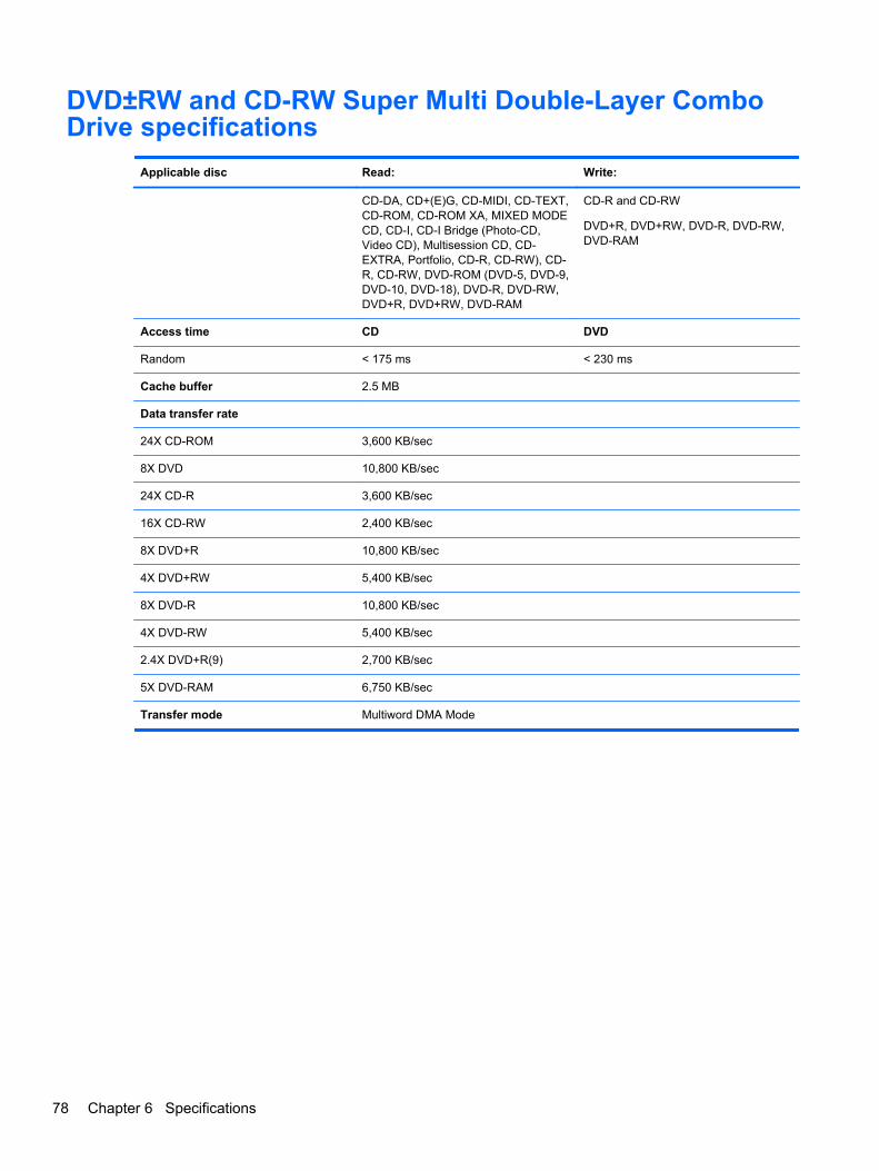
DVD±RW and CD-RW Super Multi Double-Layer ComboDrive specifications
Applicable disc Read: Write:
CD-DA, CD+(E)G, CD-MIDI, CD-TEXT,CD-ROM, CD-ROM XA, MIXED MODECD, CD-I, CD-I Bridge (Photo-CD,Video CD), Multisession CD, CD-EXTRA, Portfolio, CD-R, CD-RW), CD-R, CD-RW, DVD-ROM (DVD-5, DVD-9,DVD-10, DVD-18), DVD-R, DVD-RW,DVD+R, DVD+RW, DVD-RAM
CD-R and CD-RW
DVD+R, DVD+RW, DVD-R, DVD-RW,DVD-RAM
Access time CD DVD
Random < 175 ms < 230 ms
Cache buffer 2.5 MB
Data transfer rate
24X CD-ROM 3,600 KB/sec
8X DVD 10,800 KB/sec
24X CD-R 3,600 KB/sec
16X CD-RW 2,400 KB/sec
8X DVD+R 10,800 KB/sec
4X DVD+RW 5,400 KB/sec
8X DVD-R 10,800 KB/sec
4X DVD-RW 5,400 KB/sec
2.4X DVD+R(9) 2,700 KB/sec
5X DVD-RAM 6,750 KB/sec
Transfer mode Multiword DMA Mode
78 Chapter 6 Specifications
7 Backup and recovery
Recovery after a system failure is as good as your most recent backup. HP recommends that youcreate recovery discs immediately after software setup. As you add new software and data files, youshould continue to back up your system on a regular basis to maintain a reasonably current backup.
Tools provided by the operating system and HP Recovery Manager software are designed to helpyou with the following tasks for safeguarding your information and restoring it in case of a computerfailure:
● Creating a set of recovery discs (Recovery Manager software feature)
● Backing up your information
● Creating system restore points
● Recovering a program or driver
● Performing a full system recovery (from the partition or recovery discs)
NOTE: Recovery discs have been included if your computer does not have a partition. Use thesediscs to recover your operating system and software. To check for the presence of a recoverypartition, click Start, right-click Computer, click Manage, and then click Disk Management. If thepartition is present, an HP Recovery drive is listed in the window.
Recovery discsHP recommends that you create recovery discs to be sure that you can restore your computer to itsoriginal factory state if the hard drive fails, or if for any reason you cannot recover using the recoverypartition tools. Create these discs after setting up the computer for the first time.
Handle these discs carefully and keep them in a safe place. The software allows the creation of onlyone set of recovery discs.
NOTE: If your computer does not include an integrated optical drive, you can use an optionalexternal optical drive (purchased separately) to create recovery discs, or you can purchase recoverydiscs for your computer from the HP Web site. If you use an external optical drive, it must beconnected directly to a USB port on the computer, not to a USB port on an external device, such as aUSB hub.
Guidelines:
● Purchase high-quality DVD-R, DVD+R, BD-R (writable Blu-ray), or CD-R discs. DVDs and BDshave a much higher storage capacity than CDs. If you use CDs, up to 20 discs may be required,whereas only a few DVDs or BDs are required.
NOTE: Read-write discs, such as CD-RW, DVD±RW, double-layer DVD±RW, and BD-RE(rewritable Blu-ray) discs, are not compatible with the Recovery Manager software.
● The computer must be connected to AC power during this process.
● Only one set of recovery discs can be created per computer.
Recovery discs 79
● Number each disc before inserting it into the optical drive.
● If necessary, you can exit the program before you have finished creating the recovery discs. Thenext time you open Recovery Manager, you will be prompted to continue the disc creationprocess.
To create a set of recovery discs:
1. Select Start > All Programs > Recovery Manager > Recovery Disc Creation.
2. Follow the on-screen instructions.
Performing a system recoveryRecovery Manager software allows you to repair or restore the computer to its original factory state.Recovery Manager works from recovery discs or from a dedicated recovery partition (select modelsonly) on the hard drive.
Note the following when performing a system recovery:
● You can recover only files that you have previously backed up. HP recommends that you useHP Recovery Manager to create a set of recovery discs (entire drive backup) as soon as you setup the computer.
● Windows has its own built-in repair features, such as System Restore. If you have not alreadytried these features, try them before using Recovery Manager.
● Recovery Manager recovers only software that was preinstalled at the factory. Software notprovided with this computer must be downloaded from the manufacturer's Web site or reinstalledfrom the disc provided by the manufacturer.
Recovering using the dedicated recovery partition
On some models, you can perform a recovery from the partition on the hard drive, accessed byclicking Start or pressing the f11 key. This type of recovery restores the computer to its factorycondition without using recovery discs.
To restore the computer from the partition, follow these steps:
1. Access Recovery Manager in either of the following ways:
● Select Start > All Programs > Recovery Manager > Recovery Manager.
– or –
● Turn on or restart the computer, and then press esc while the “Press the ESC key forStartup Menu” message is displayed at the bottom of the screen. Then, press f11 while the“F11 (HP Recovery)” message is displayed on the screen.
2. Click System Recovery in the Recovery Manager window.
3. Follow the on-screen instructions.
Recovering using the recovery discs
1. If possible, back up all personal files.
2. Insert the first recovery disc into the optical drive on your computer or an optional externaloptical drive, and then restart the computer.
3. Follow the on-screen instructions.
80 Chapter 7 Backup and recovery
Backing up your informationYou should back up your computer files on a regular schedule to maintain a current backup. You canback up your information to an optional external hard drive, a network drive, or discs. Back up yoursystem at the following times:
● At regularly scheduled times
NOTE: Set reminders to back up your information periodically.
● Before the computer is repaired or restored
● Before you add or modify hardware or software
Guidelines:
● Create system restore points using the Windows System Restore feature, and periodically copythem to an optical disc or an external hard drive. For more information on using system restorepoints, refer to “Using system restore points”.
● Store personal files in the Documents library and back up this folder periodically.
● Save customized settings in a window, toolbar, or menu bar by taking a screen shot of yoursettings. The screen shot can be a time-saver if you have to reset your preferences.
Using Windows Backup and Restore
Windows Backup and Restore allows you to back up individual files or back up the entire computerimage.
Guidelines:
● Be sure that the computer is connected to AC power before you start the backup process.
● Allow enough time to complete the backup process. Depending on file sizes, it may take over anhour.
To create a backup:
1. Select Start > Control Panel > System and Security > Backup and Restore.
2. Follow the on-screen instructions to schedule and create a backup.
NOTE: Windows includes the User Account Control feature to improve the security of the computer.You may be prompted for your permission or password for tasks such as installing software, runningutilities, or changing Windows settings. Refer to Help and Support for more information.
Backing up your information 81
Using system restore points
A system restore point allows you to save and name a snapshot of your hard drive at a specific pointin time. You can then recover back to that point if you want to reverse subsequent changes.
NOTE: Recovering to an earlier restore point does not affect data files saved or e-mails createdsince the last restore point.
You also can create additional restore points to provide increased protection for your files andsettings.
When to create restore points
● Before you add or extensively modify software or hardware
● Periodically, whenever the computer is functioning optimally
NOTE: If you revert to a restore point and then change your mind, you can reverse the restoration.
Create a system restore point
1. Select Start > Control Panel > System and Security > System.
2. In the left pane, click System Protection.
3. Click the System Protection tab.
4. Follow the on-screen instructions.
Restore to a previous date and time
To revert to a restore point (created at a previous date and time), when the computer was functioningoptimally, follow these steps:
1. Select Start > Control Panel > System and Security > System.
2. In the left pane, click System protection.
3. Click the System Protection tab.
4. Click System Restore.
5. Follow the on-screen instructions.
82 Chapter 7 Backup and recovery
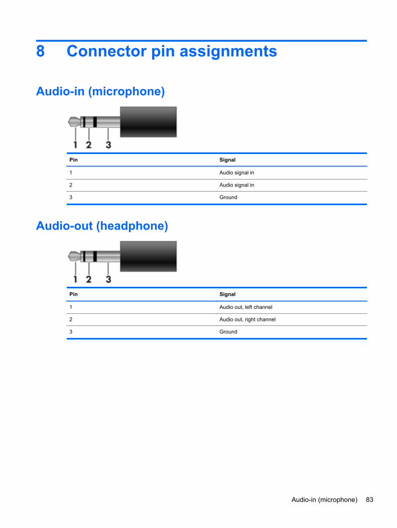
8 Connector pin assignments
Audio-in (microphone)
Pin Signal
1 Audio signal in
2 Audio signal in
3 Ground
Audio-out (headphone)
Pin Signal
1 Audio out, left channel
2 Audio out, right channel
3 Ground
Audio-in (microphone) 83
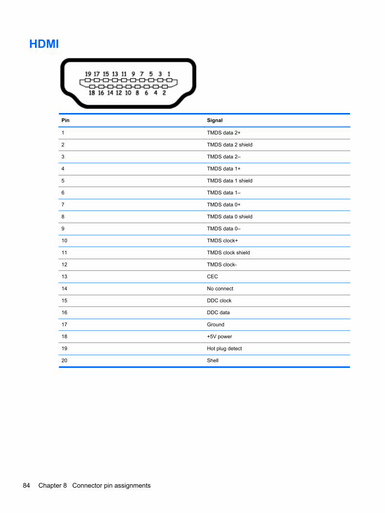
HDMI
Pin Signal
1 TMDS data 2+
2 TMDS data 2 shield
3 TMDS data 2–
4 TMDS data 1+
5 TMDS data 1 shield
6 TMDS data 1–
7 TMDS data 0+
8 TMDS data 0 shield
9 TMDS data 0–
10 TMDS clock+
11 TMDS clock shield
12 TMDS clock-
13 CEC
14 No connect
15 DDC clock
16 DDC data
17 Ground
18 +5V power
19 Hot plug detect
20 Shell
84 Chapter 8 Connector pin assignments
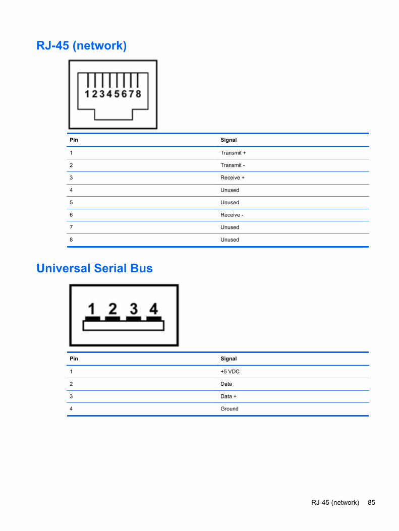
RJ-45 (network)
Pin Signal
1 Transmit +
2 Transmit -
3 Receive +
4 Unused
5 Unused
6 Receive -
7 Unused
8 Unused
Universal Serial Bus
Pin Signal
1 +5 VDC
2 Data
3 Data +
4 Ground
RJ-45 (network) 85
9 Power cord set requirements
The wide-range input feature of the computer permits it to operate from any line voltage from 100 to120 volts AC, or from 220 to 240 volts AC
The 3-conductor power cord set included with the computer meets the requirements for use in thecountry or region where the equipment is purchased.
Power cord sets for use in other countries and regions must meet the requirements of the country orregion where the computer is used.
Requirements for all countriesThe following requirements are applicable to all countries and regions:
● The length of the power cord set must be at least 1.5 m (5.0 ft) and no more than 2.0 m (6.5 ft).
● All power cord sets must be approved by an acceptable accredited agency responsible forevaluation in the country or region where the power cord set will be used.
● The power cord sets must have a minimum current capacity of 10 amps and a nominal voltagerating of 125 or 250 V AC, as required by the power system of each country or region.
● The appliance coupler must meet the mechanical configuration of an EN 60 320/IEC 320Standard Sheet C13 connector for mating with the appliance inlet on the back of the computer.
86 Chapter 9 Power cord set requirements
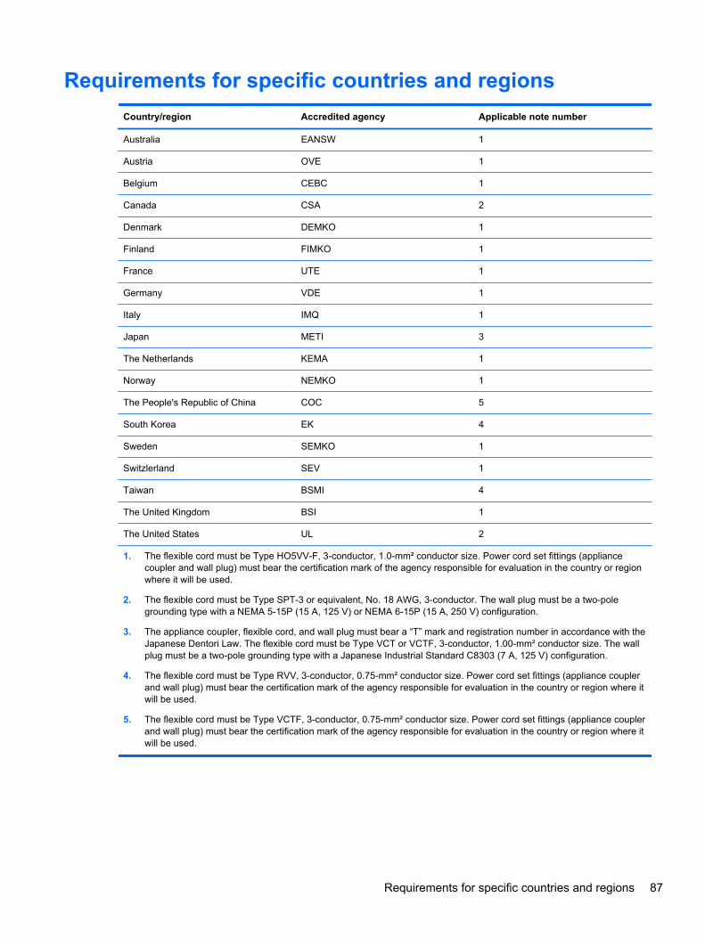
Requirements for specific countries and regions
Country/region Accredited agency Applicable note number
Australia EANSW 1
Austria OVE 1
Belgium CEBC 1
Canada CSA 2
Denmark DEMKO 1
Finland FIMKO 1
France UTE 1
Germany VDE 1
Italy IMQ 1
Japan METI 3
The Netherlands KEMA 1
Norway NEMKO 1
The People's Republic of China COC 5
South Korea EK 4
Sweden SEMKO 1
Switzlerland SEV 1
Taiwan BSMI 4
The United Kingdom BSI 1
The United States UL 2
1. The flexible cord must be Type HO5VV-F, 3-conductor, 1.0-mm² conductor size. Power cord set fittings (appliancecoupler and wall plug) must bear the certification mark of the agency responsible for evaluation in the country or regionwhere it will be used.
2. The flexible cord must be Type SPT-3 or equivalent, No. 18 AWG, 3-conductor. The wall plug must be a two-polegrounding type with a NEMA 5-15P (15 A, 125 V) or NEMA 6-15P (15 A, 250 V) configuration.
3. The appliance coupler, flexible cord, and wall plug must bear a “T” mark and registration number in accordance with theJapanese Dentori Law. The flexible cord must be Type VCT or VCTF, 3-conductor, 1.00-mm² conductor size. The wallplug must be a two-pole grounding type with a Japanese Industrial Standard C8303 (7 A, 125 V) configuration.
4. The flexible cord must be Type RVV, 3-conductor, 0.75-mm² conductor size. Power cord set fittings (appliance couplerand wall plug) must bear the certification mark of the agency responsible for evaluation in the country or region where itwill be used.
5. The flexible cord must be Type VCTF, 3-conductor, 0.75-mm² conductor size. Power cord set fittings (appliance couplerand wall plug) must bear the certification mark of the agency responsible for evaluation in the country or region where itwill be used.
Requirements for specific countries and regions 87
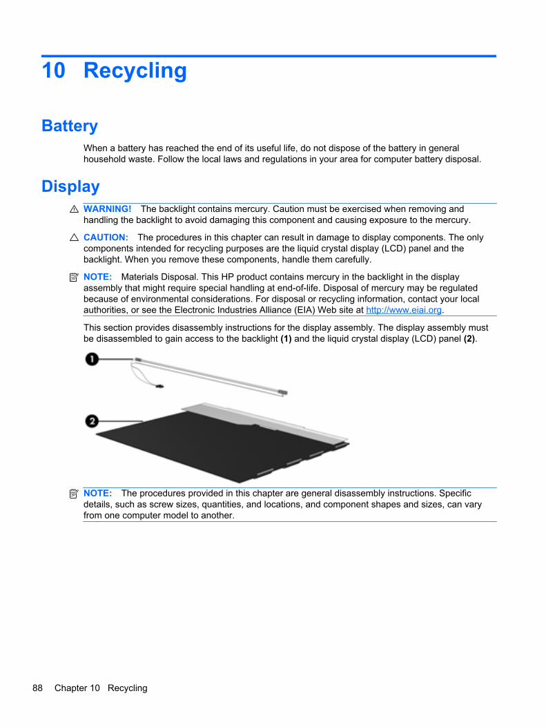
10 Recycling
BatteryWhen a battery has reached the end of its useful life, do not dispose of the battery in generalhousehold waste. Follow the local laws and regulations in your area for computer battery disposal.
DisplayWARNING! The backlight contains mercury. Caution must be exercised when removing andhandling the backlight to avoid damaging this component and causing exposure to the mercury.
CAUTION: The procedures in this chapter can result in damage to display components. The onlycomponents intended for recycling purposes are the liquid crystal display (LCD) panel and thebacklight. When you remove these components, handle them carefully.
NOTE: Materials Disposal. This HP product contains mercury in the backlight in the displayassembly that might require special handling at end-of-life. Disposal of mercury may be regulatedbecause of environmental considerations. For disposal or recycling information, contact your localauthorities, or see the Electronic Industries Alliance (EIA) Web site at http://www.eiai.org.
This section provides disassembly instructions for the display assembly. The display assembly mustbe disassembled to gain access to the backlight (1) and the liquid crystal display (LCD) panel (2).
NOTE: The procedures provided in this chapter are general disassembly instructions. Specificdetails, such as screw sizes, quantities, and locations, and component shapes and sizes, can varyfrom one computer model to another.
88 Chapter 10 Recycling
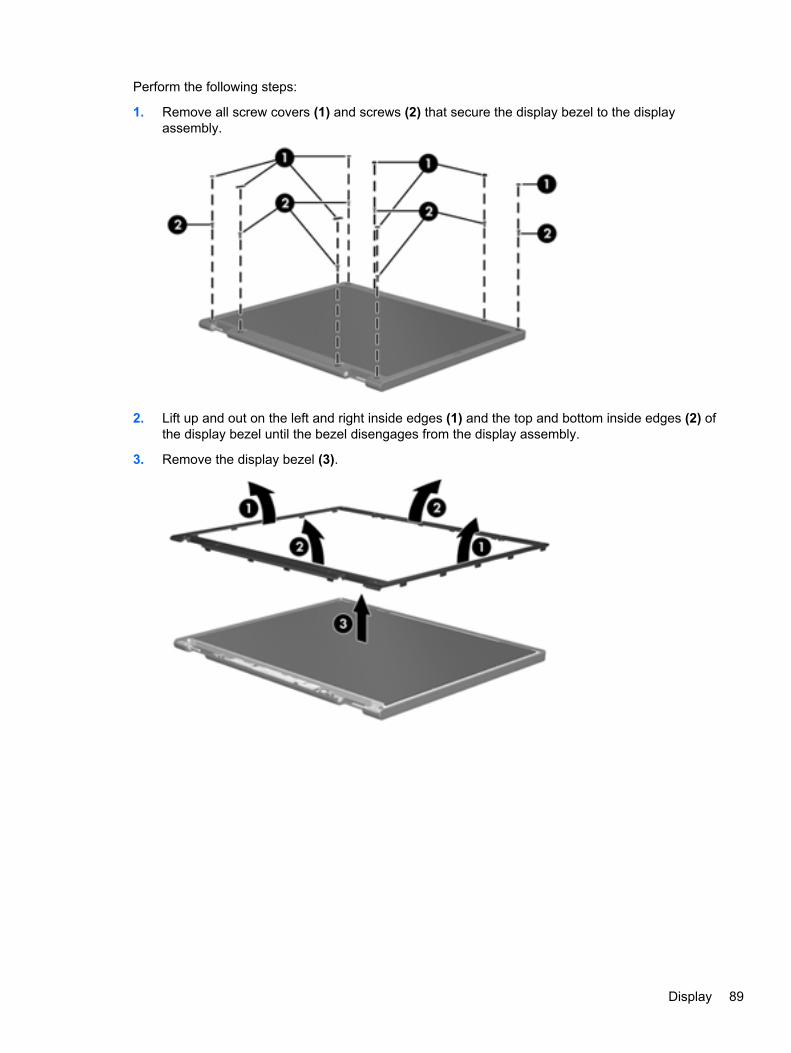
Perform the following steps:
1. Remove all screw covers (1) and screws (2) that secure the display bezel to the displayassembly.
2. Lift up and out on the left and right inside edges (1) and the top and bottom inside edges (2) ofthe display bezel until the bezel disengages from the display assembly.
3. Remove the display bezel (3).
Display 89
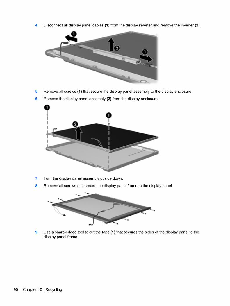
4. Disconnect all display panel cables (1) from the display inverter and remove the inverter (2).
5. Remove all screws (1) that secure the display panel assembly to the display enclosure.
6. Remove the display panel assembly (2) from the display enclosure.
7. Turn the display panel assembly upside down.
8. Remove all screws that secure the display panel frame to the display panel.
9. Use a sharp-edged tool to cut the tape (1) that secures the sides of the display panel to thedisplay panel frame.
90 Chapter 10 Recycling
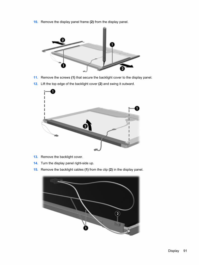
10. Remove the display panel frame (2) from the display panel.
11. Remove the screws (1) that secure the backlight cover to the display panel.
12. Lift the top edge of the backlight cover (2) and swing it outward.
13. Remove the backlight cover.
14. Turn the display panel right-side up.
15. Remove the backlight cables (1) from the clip (2) in the display panel.
Display 91
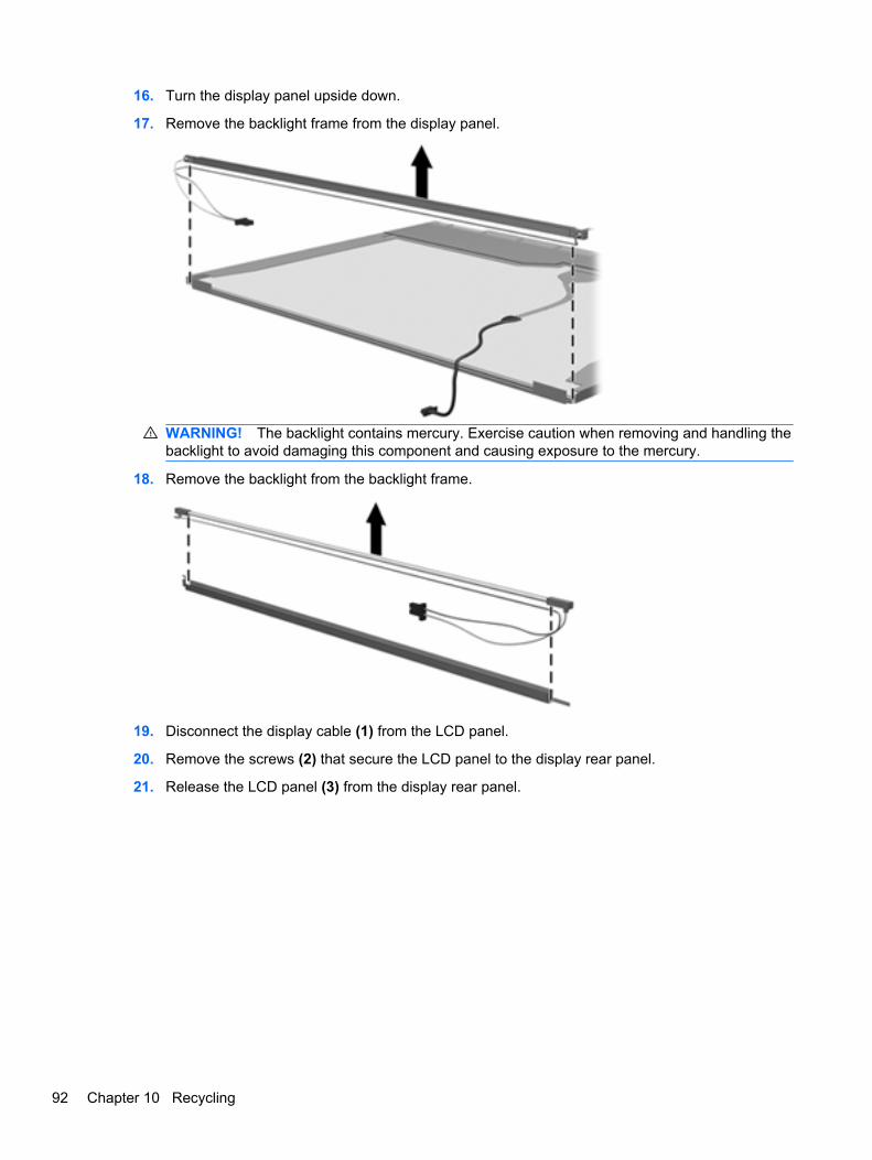
16. Turn the display panel upside down.
17. Remove the backlight frame from the display panel.
WARNING! The backlight contains mercury. Exercise caution when removing and handling thebacklight to avoid damaging this component and causing exposure to the mercury.
18. Remove the backlight from the backlight frame.
19. Disconnect the display cable (1) from the LCD panel.
20. Remove the screws (2) that secure the LCD panel to the display rear panel.
21. Release the LCD panel (3) from the display rear panel.
92 Chapter 10 Recycling
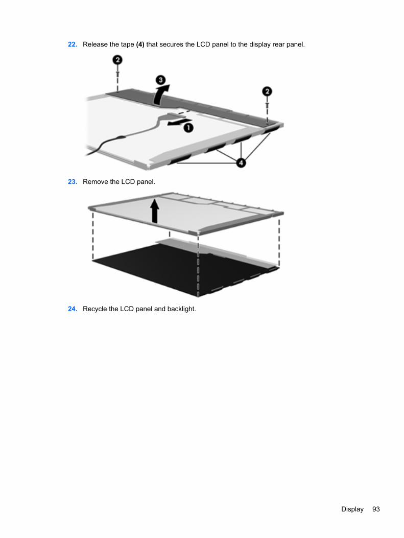
22. Release the tape (4) that secures the LCD panel to the display rear panel.
23. Remove the LCD panel.
24. Recycle the LCD panel and backlight.
Display 93
Index
AAC adapter, spare part numbers
21, 25accessory battery connector 13action keys 6antenna, locations 9audio, product description 2audio-in jack
connector pinout 83location 11
audio-out jackconnector pinout 83location 11
audio/USB boardremoval 55spare part number 17, 25, 55
Bbase enclosure, spare part
numbers 18, 25, 26battery
removal 34spare part numbers 18, 23, 34
battery bay 13battery connector board
removal 48spare part number 18, 26, 48
battery coverillustrated 20removal 34spare part number 35
battery light 12battery release latch 13Bluetooth compartment 10Bluetooth module
removal 56spare part number 17, 27, 56
bottom components 13button component 5buttons
power 5TouchPad 8
CCable Kit, spare part number 17,
25cables, service considerations 28chipset, product description 1components
bottom 13button 5display 9front 10keys 6left side 11lights 7right side 12TouchPad 8
computer feetlocations 33spare part number 33
computer part number 14, 33computer specifications 76connector pinout
audio-in jack 83audio-out jack 83HDMI port 84headphone jack 83microphone jack 83network jack 85RJ-45 jack 85Universal Serial Bus (USB)
port 85connectors, service
considerations 28
DDigital Media Slot 10display assembly
removal 70spare part numbers 16, 24,
25, 26, 70display components 9display panel, product
description 1display specifications 77
Door Kitcomponents 20spare part number 17, 20, 25
drive light 12drives, preventing damage 29DVD±RW and CD-RW Super Multi
Double-Layer Combo Driveprecautions 29removal 59spare part number 17, 21, 24,
59specifications 78
Eelectrostatic discharge 29equipment guidelines 32eSATA port 12esc key 6Ethernet, product description 2external media cards, product
description 3
Ffan/heat sink assembly
removal 65spare part number 18, 25, 65
feetlocations 33spare part number 33
fn key 6front components 10
Ggraphics, product description 1grounding guidelines 29guidelines
equipment 32grounding 29packaging 31transporting 31workstation 31
Hhard drive
precautions 29
94 Index
product description 2removal 36spare part numbers 18, 20,
23, 24, 26, 27, 36specifications 77
Hard Drive Hardware Kit, sparepart number 19, 21, 24, 37
HDMI portconnector pinout 84location 12
HDMI to VGA adapter, spare partnumber 21, 22
headphone jackconnector pinout 83location 11
headphone, spare part numbers21
Jjacks
audio-in 11audio-out 11headphone 11microphone 11network 12RJ-45 12
Kkey components 6keyboard
product description 3removal 52spare part numbers 16, 24,
25, 26, 52keys
action 6esc 6fn 6optical drive eject 6Windows applications 6Windows logo 6
Lleft-side components 11light components 7lights
battery 12drive 12mute 7power 7, 12
webcam 9wireless 7
Mmass storage device
removal 36spare part numbers 18, 19,
20, 23, 24, 26, 27, 36memory module
product description 1removal 46spare part numbers 19, 23, 46
memory module/wireless modulecompartment 13
memory module/wireless modulecompartment cover
illustrated 20removal 42
microphonelocation 9product description 2
microphone jackconnector pinout 83location 11
MiniDisplay Port 12model description 14, 33model name 1mute light 7
Nnetwork jack
connector pinout 85location 12
Ooperating system, product
description 4optical drive
location 11precautions 29product description 2removal 59spare part number 17, 21, 24,
59specifications 78
optical drive eject key 6
Ppackaging guidelines 31part number listing, sequential 22
plastic parts, serviceconsiderations 28
pointing device, productdescription 3
portseSATA 12HDMI 12Mini DisplayPort 12product description 3Universal Serial Bus (USB)
11, 12power button 5power connector 12power connector cable
removal 61spare part number 17, 25, 61
power cordset requirements 86spare part numbers 21, 22, 25
power light 7, 12power requirements, product
description 3processor
product description 1removal 67spare part numbers 17, 23,
25, 27, 67product description
audio 2chipset 1display panel 1Ethernet 2external media cards 3graphics 1hard drives 2keyboard 3memory module 1microphone 2operating system 4optical drive 2pointing device 3ports 3power requirements 3processors 1product name 1security 3serviceability 4video 2wireless 3
product name 1, 14, 33
Index 95
product number 14, 33protective cover, spare part
numbers 22, 26
Rremoval/replacement
preliminaries 28procedures 32
right-side components 12RJ-45 jack
connector pinout 85location 12
RTC batteryremoval 45spare part number 19, 22, 45
SScrew Kit, spare part number 22,
25security cable slot 12security, product description 3serial number 14, 33service considerations
cables 28connectors 28plastic parts 28
service tag 14, 33serviceability, product
description 4SIM slot 13SIM, removal 35SIM/WWAN board
removal 57spare part number 17, 25, 57
solid-state driveremoval 36spare part numbers 19, 21,
24, 36speakers
location 10removal 69spare part number 18, 25, 69
specificationscomputer 76display 77DVD±RW and CD-RW Super
Multi Double-Layer ComboDrive 78
hard drive 77optical drive 78
system boardremoval 62spare part numbers 17, 23, 62
Ttools required 28top cover
removal 50spare part numbers 17, 25,
26, 50TouchPad 8TouchPad button 8TouchPad components 8TouchPad off indicator 7, 8transporting guidelines 31
UUniversal Serial Bus (USB) port
connector pinout 85location 11, 12
Vvents 12, 13video, product description 2
Wwarranty period 14, 33webcam 9webcam light 9Windows applications key 6Windows logo key 6wireless antenna, locations 9wireless light 7wireless, product description 3WLAN module
removal 41spare part numbers 19, 22,
23, 41workstation guidelines 31WWAN module
removal 38spare part number 18, 22, 38
96 Index


