HP Compaq LA2006x, LA2206x, and LA2306x LED Backlit LCD...
52
HP Compaq LA2006x, LA2206x, and LA2306x LED Backlit LCD Monitors User Guide
Transcript of HP Compaq LA2006x, LA2206x, and LA2306x LED Backlit LCD...
HP Compaq LA2006x, LA2206x, andLA2306x LED Backlit LCD Monitors
User Guide

© 2010, 2011 Hewlett-PackardDevelopment Company, L.P.
Microsoft, Windows, and Windows Vista areeither trademarks or registered trademarksof Microsoft Corporation in the UnitedStates and/or other countries.
The only warranties for HP products andservices are set forth in the expresswarranty statements accompanying suchproducts and services . Nothing hereinshould be construed as constituting anadditional warranty. HP shall not be liablefor technical or editorial errors or omissionscontained herein.
This document contains proprietaryinformation that is protected by copyright.No part of this document may bephotocopied, reproduced, or translated toanother language without the prior writtenconsent of Hewlett-Packard Company.
Second Edition (June 2011)
Document Part Number: 630579-002

About This Guide
This guide provides information on setting up the monitor, installing drivers, using the on-screendisplay menu, troubleshooting and technical specifications.
WARNING! Text set off in this manner indicates that failure to follow directions could result in bodilyharm or loss of life.
CAUTION: Text set off in this manner indicates that failure to follow directions could result indamage to equipment or loss of information.
NOTE: Text set off in this manner provides important supplemental information.
ENWW iii

iv About This Guide ENWW

Table of contents
1 Product Features ............................................................................................................................................ 1
HP LCD Monitors ................................................................................................................................. 1
2 Safety and Maintenance Guidelines .............................................................................................................. 3
Important Safety Information ................................................................................................................ 3
Maintenance Guidelines ....................................................................................................................... 3
Cleaning the Monitor ............................................................................................................ 4
Shipping the Monitor ............................................................................................................ 4
3 Setting Up the Monitor ................................................................................................................................... 5
Unfolding the Monitor Pedestal Base ................................................................................................... 5
Rear Components ................................................................................................................................ 6
Connecting the Cables ......................................................................................................................... 7
Adjusting the Monitor ............................................................................................................................ 9
Turning on the Monitor ....................................................................................................................... 11
Connecting USB Devices ................................................................................................................... 12
Removing the Monitor Pedestal Base ................................................................................................ 13
Mounting the Monitor ......................................................................................................... 14
Locating the Rating Labels ................................................................................................................. 15
Installing a Cable Lock ....................................................................................................................... 15
4 Operating the Monitor .................................................................................................................................. 16
Software and Utilities .......................................................................................................................... 16
The Information File ........................................................................................................... 16
The Image Color Matching File .......................................................................................... 16
Installing the .INF and .ICM Files ....................................................................................................... 17
Installing from the CD ........................................................................................................ 17
Downloading from the Worldwide Web .............................................................................. 17
Using the Auto-Adjustment Function .................................................................................................. 18
Front Panel Controls .......................................................................................................................... 19
Adjusting the Monitor Settings ............................................................................................................ 20
Using the On-Screen Display Menu .................................................................................. 20
OSD Menu Selections ....................................................................................... 21
Optimizing Image Performance ......................................................................... 25
Using the HP Display Assistant Utility ............................................................................... 26
Identifying Monitor Conditions ............................................................................................................ 26
ENWW v
Sleep Timer Mode .............................................................................................................................. 27
Appendix A Troubleshooting .......................................................................................................................... 29
Solving Common Problems ................................................................................................................ 29
Online Technical Support ................................................................................................................... 30
Preparing to Call Technical Support ................................................................................................... 30
Appendix B Technical Specifications ............................................................................................................ 31
LA2006x Model .................................................................................................................................. 31
LA2206x Model .................................................................................................................................. 32
LA2306x Model .................................................................................................................................. 33
Recognizing Preset Display Resolutions ............................................................................................ 35
LA2006x Model .................................................................................................................. 35
LA2206x Model .................................................................................................................. 35
LA2306x Model .................................................................................................................. 36
Entering User Modes .......................................................................................................................... 37
Energy Saver Feature ........................................................................................................................ 37
Appendix C Agency Regulatory Notices ....................................................................................................... 38
Federal Communications Commission Notice ................................................................................... 38
Modifications ...................................................................................................................... 38
Cables ................................................................................................................................ 38
Declaration of Conformity for Products Marked with the FCC Logo (United States Only) ................. 38
Canadian Notice ................................................................................................................................. 39
Avis Canadien .................................................................................................................................... 39
European Union Regulatory Notice .................................................................................................... 39
German Ergonomics Notice ............................................................................................................... 40
Japanese Notice ................................................................................................................................. 40
Korean Notice ..................................................................................................................................... 40
Power Cord Set Requirements ........................................................................................................... 40
Japanese Power Cord Requirements ................................................................................ 40
Product Environmental Notices .......................................................................................................... 41
ENERGY STAR® Qualification .......................................................................................... 41
Materials Disposal ............................................................................................................. 41
Disposal of Waste Equipment by Users in Private Household in the European Union ..... 42
HP Recycling Program ...................................................................................................... 42
Chemical Substances ........................................................................................................ 42
Restriction of Hazardous Substances (RoHS) ................................................................... 42
Turkey EEE Regulation ..................................................................................................... 43
vi ENWW

Appendix D LCD Monitor Quality and Pixel Policy ....................................................................................... 44
ENWW vii

viii ENWW
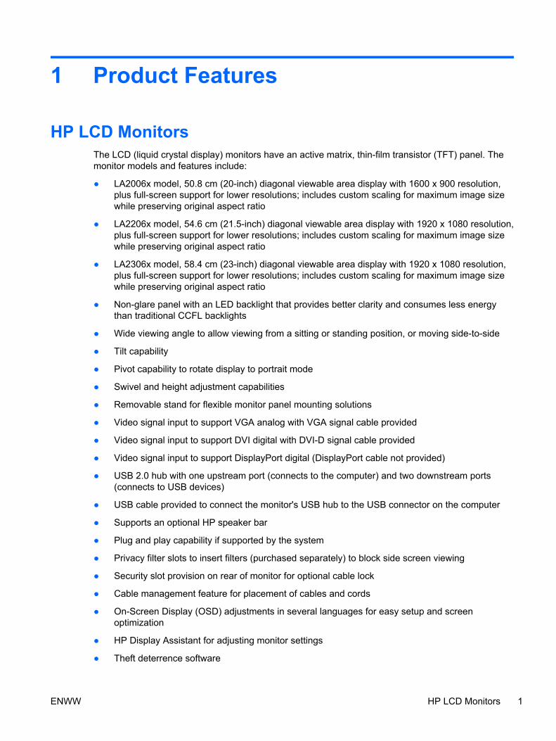
1 Product Features
HP LCD MonitorsThe LCD (liquid crystal display) monitors have an active matrix, thin-film transistor (TFT) panel. Themonitor models and features include:
● LA2006x model, 50.8 cm (20-inch) diagonal viewable area display with 1600 x 900 resolution,plus full-screen support for lower resolutions; includes custom scaling for maximum image sizewhile preserving original aspect ratio
● LA2206x model, 54.6 cm (21.5-inch) diagonal viewable area display with 1920 x 1080 resolution,plus full-screen support for lower resolutions; includes custom scaling for maximum image sizewhile preserving original aspect ratio
● LA2306x model, 58.4 cm (23-inch) diagonal viewable area display with 1920 x 1080 resolution,plus full-screen support for lower resolutions; includes custom scaling for maximum image sizewhile preserving original aspect ratio
● Non-glare panel with an LED backlight that provides better clarity and consumes less energythan traditional CCFL backlights
● Wide viewing angle to allow viewing from a sitting or standing position, or moving side-to-side
● Tilt capability
● Pivot capability to rotate display to portrait mode
● Swivel and height adjustment capabilities
● Removable stand for flexible monitor panel mounting solutions
● Video signal input to support VGA analog with VGA signal cable provided
● Video signal input to support DVI digital with DVI-D signal cable provided
● Video signal input to support DisplayPort digital (DisplayPort cable not provided)
● USB 2.0 hub with one upstream port (connects to the computer) and two downstream ports(connects to USB devices)
● USB cable provided to connect the monitor's USB hub to the USB connector on the computer
● Supports an optional HP speaker bar
● Plug and play capability if supported by the system
● Privacy filter slots to insert filters (purchased separately) to block side screen viewing
● Security slot provision on rear of monitor for optional cable lock
● Cable management feature for placement of cables and cords
● On-Screen Display (OSD) adjustments in several languages for easy setup and screenoptimization
● HP Display Assistant for adjusting monitor settings
● Theft deterrence software
ENWW HP LCD Monitors 1

● HDCP copy protection on DVI and DisplayPort inputs
● Software and documentation CD that includes monitor drivers and product documentation
● Energy saver feature to meet requirements for reduced power consumption
● Energy Star® qualified
● Intelligent Management AssetControl
● Compliant with the following regulated specifications:
◦ European Union CE Directives
◦ Swedish TCO Requirements
2 Chapter 1 Product Features ENWW

2 Safety and Maintenance Guidelines
Important Safety InformationA power cord is included with the monitor. If another cord is used, use only a power source andconnection appropriate for this monitor. For information on the correct power cord set to use with themonitor, refer to the Power Cord Set Requirements on page 40.
WARNING! To reduce the risk of electric shock or damage to the equipment:
• Do not disable the power cord grounding feature. The grounding plug is an important safety feature.
• Plug the power cord in a grounded (earthed) outlet that is easily accessible at all times.
• Disconnect power from the product by unplugging the power cord from the electrical outlet.
For your safety, do not place anything on power cords or cables. Arrange them so that no one mayaccidentally step on or trip over them. Do not pull on a cord or cable. When unplugging from theelectrical outlet, grasp the cord by the plug.
To reduce the risk of serious injury, read the Safety and Comfort Guide. It describes properworkstation, setup, posture, and health and work habits for computer users, and provides importantelectrical and mechanical safety information. This guide is located on the Web at http://www.hp.com/ergo and/or on the documentation CD, if one is included with the monitor.
CAUTION: For the protection of the monitor, as well as the computer, connect all power cords forthe computer and its peripheral devices (such as a monitor, printer, scanner) to some form of surgeprotection device such as a power strip or Uninterruptible Power Supply (UPS). Not all power stripsprovide surge protection; the power strips must be specifically labeled as having this ability. Use apower strip whose manufacturer offers a Damage Replacement Policy so you can replace theequipment, if surge protection fails.
Use the appropriate and correctly sized furniture designed to properly support your HP LCD monitor.
WARNING! LCD monitors that are inappropriately situated on dressers, bookcases, shelves, desks,speakers, chests, or carts may fall over and cause personal injury.
Care should be taken to route all cords and cables connected to the LCD monitor so that they can notbe pulled, grabbed, or tripped over.
Maintenance GuidelinesTo enhance the performance and extend the life of the monitor:
● Do not open the monitor cabinet or attempt to service this product yourself. Adjust only thosecontrols that are covered in the operating instructions. If the monitor is not operating properly orhas been dropped or damaged, contact an authorized HP dealer, reseller, or service provider.
● Use only a power source and connection appropriate for this monitor, as indicated on the label/back plate of the monitor.
● Be sure the total ampere rating of the products connected to the outlet does not exceed thecurrent rating of the electrical outlet, and the total ampere rating of the products connected to thecord does not exceed the rating of the cord. Look on the power label to determine the ampererating (AMPS or A) for each device.
ENWW Important Safety Information 3

● Install the monitor near an outlet that you can easily reach. Disconnect the monitor by graspingthe plug firmly and pulling it from the outlet. Never disconnect the monitor by pulling the cord.
● Turn the monitor off when not in use. You can substantially increase the life expectancy of themonitor by using a screen saver program and turning off the monitor when not in use.
NOTE: Monitors with a “burned-in image” are not covered under the HP warranty.
● Slots and openings in the cabinet are provided for ventilation. These openings must not beblocked or covered. Never push objects of any kind into cabinet slots or other openings.
● Do not drop the monitor or place it on an unstable surface.
● Do not allow anything to rest on the power cord. Do not walk on the cord.
● Keep the monitor in a well-ventilated area, away from excessive light, heat or moisture.
● When removing the monitor stand, you must lay the monitor face down on a soft area to preventit from getting scratched, defaced, or broken.
Cleaning the Monitor
1. Turn off the monitor and unplug the power cord from the back of the unit.
2. Dust the monitor by wiping the screen and the cabinet with a soft, clean antistatic cloth.
3. For more difficult cleaning situations, use a 50/50 mix of water and Isopropyl alcohol.
CAUTION: Spray the cleaner onto a cloth and use the damp cloth to gently wipe the screensurface. Never spray the cleaner directly on the screen surface. It may run behind the bezel anddamage the electronics.
CAUTION: Do not use cleaners that contain any petroleum based materials such as benzene,thinner, or any volatile substance to clean the monitor screen or cabinet. These chemicals maydamage the monitor.
Shipping the Monitor
Keep the original packing box in a storage area. You may need it later if you move or ship themonitor.
4 Chapter 2 Safety and Maintenance Guidelines ENWW
3 Setting Up the Monitor
To set up the monitor, ensure that the power is turned off to the monitor, computer system, and otherattached devices, then follow the instructions below.
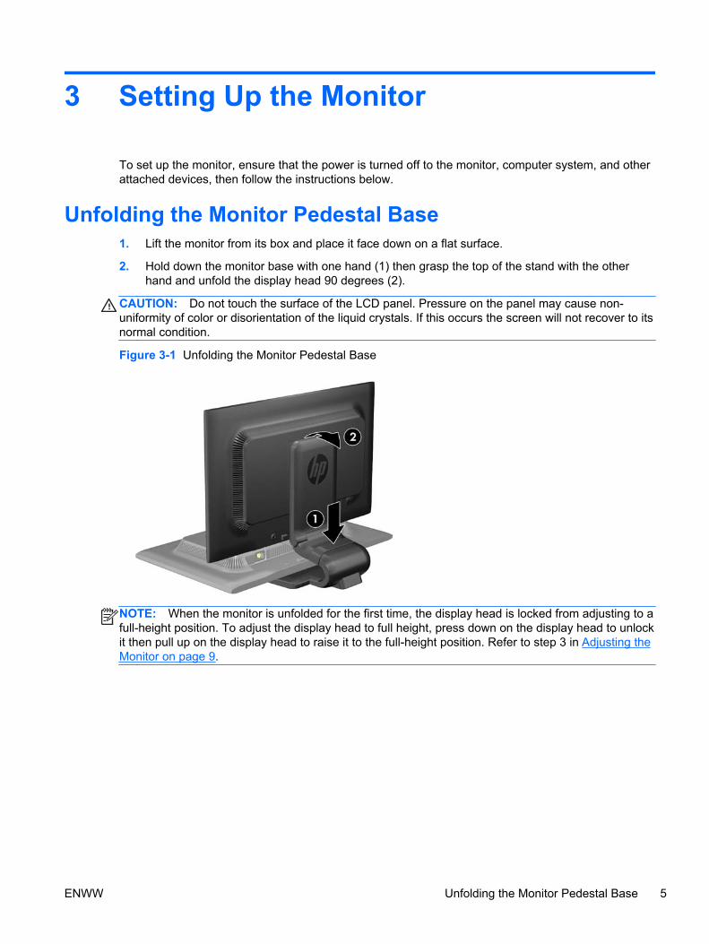
Unfolding the Monitor Pedestal Base1. Lift the monitor from its box and place it face down on a flat surface.
2. Hold down the monitor base with one hand (1) then grasp the top of the stand with the otherhand and unfold the display head 90 degrees (2).
CAUTION: Do not touch the surface of the LCD panel. Pressure on the panel may cause non-uniformity of color or disorientation of the liquid crystals. If this occurs the screen will not recover to itsnormal condition.
Figure 3-1 Unfolding the Monitor Pedestal Base
NOTE: When the monitor is unfolded for the first time, the display head is locked from adjusting to afull-height position. To adjust the display head to full height, press down on the display head to unlockit then pull up on the display head to raise it to the full-height position. Refer to step 3 in Adjusting theMonitor on page 9.
ENWW Unfolding the Monitor Pedestal Base 5

Rear ComponentsFigure 3-2 Rear Components
Component Function
1 AC Power Connector Connects the AC power cord to the monitor.
2 DisplayPort Connects the DisplayPort cable (not included) to themonitor.
3 DVI-D Connects the DVI-D cable to the monitor.
4 VGA Connects the VGA cable to the monitor.
5 USB UpstreamConnector
Connects the USB hub cable to the monitor's USB hubconnector and to a host USB port/hub.
6 USB DownstreamConnectors (2)
Connects optional USB devices to the monitor.
6 Chapter 3 Setting Up the Monitor ENWW

Connecting the Cables1. Place the monitor in a convenient, well-ventilated location near the computer.
2. Remove the cable management clip from the pedestal by pulling outward on the two sides of theclip (1) then lifting the clip off the pedestal (2).
Figure 3-3 Removing the Cable Management Clip
3. Connect a VGA signal cable, DVI-D signal cable, or DisplayPort signal cable.
NOTE: The monitor is capable of supporting either analog or digital input. The video mode isdetermined by the video cable used. The monitor will automatically determine which inputs havevalid video signals. The inputs can be selected by pressing the +/source button on the frontpanel or through the On-Screen Display (OSD) feature by pressing the Menu button.
● For analog operation, use the VGA signal cable provided. Connect the VGA signal cable tothe VGA connector on the rear of the monitor and the other end to the VGA connector onthe computer.
● For DVI digital operation, use the DVI-D signal cable provided. Connect the DVI-D signalcable to the DVI connector on the rear of the monitor and the other end to the DVIconnector on the computer.
● For DisplayPort digital operation, use a DisplayPort signal cable (not provided). Connectthe DisplayPort signal cable to the DisplayPort connector on the rear of the monitor and theother end to the DisplayPort connector on the computer.
4. Connect one end of the provided USB cable to the USB hub connector on the rear panel of thecomputer, and the other end to the upstream USB connector on the monitor.
ENWW Connecting the Cables 7

5. Connect one end of the power cord to the AC power connector on the back of the monitor, andthe other end to an electrical wall outlet.
Figure 3-4 Connecting the Cables
WARNING! To reduce the risk of electric shock or damage to the equipment:
Do not disable the power cord grounding plug. The grounding plug is an important safetyfeature.
Plug the power cord into a grounded (earthed) electrical outlet that is easily accessible at alltimes.
Disconnect power from the equipment by unplugging the power cord from the electrical outlet.
For your safety, do not place anything on power cords or cables. Arrange them so that no onemay accidentally step on or trip over them. Do not pull on a cord or cable. When unplugging fromthe electrical outlet, grasp the cord by the plug.
6. Secure the cables in place with the cable management clip. Press the clip straight down on thecurved neck of the pedestal ensuring that the tabs on the sides of the clip snap into the slots onthe pedestal.
Figure 3-5 Installing the Cable Management Clip
8 Chapter 3 Setting Up the Monitor ENWW

Adjusting the MonitorNOTE: Your monitor model may look different than the model in the following illustrations.
1. Tilt the monitor's panel forward or backward to set it to a comfortable eye level.
Figure 3-6 Tilting the Monitor
2. Swivel the monitor to the left or right for the best viewing angle.
Figure 3-7 Swiveling the Monitor
ENWW Adjusting the Monitor 9
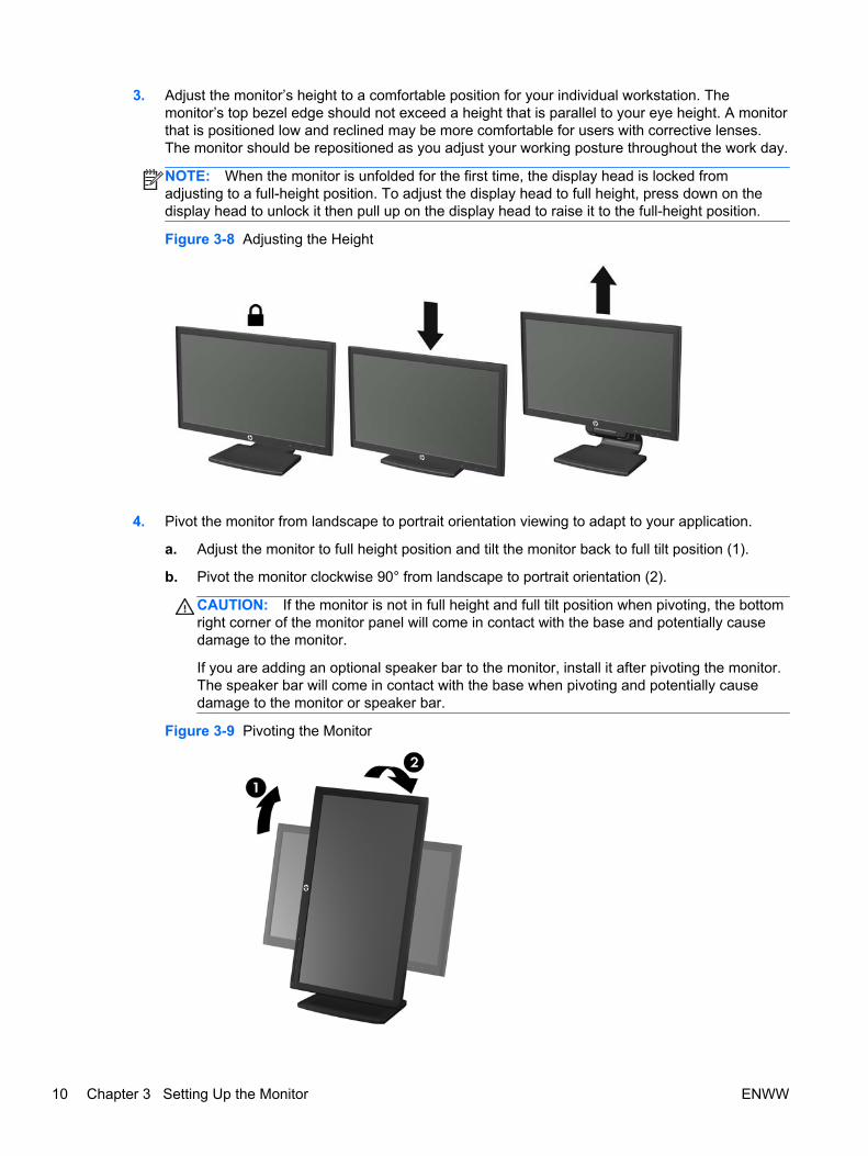
3. Adjust the monitor’s height to a comfortable position for your individual workstation. Themonitor’s top bezel edge should not exceed a height that is parallel to your eye height. A monitorthat is positioned low and reclined may be more comfortable for users with corrective lenses.The monitor should be repositioned as you adjust your working posture throughout the work day.
NOTE: When the monitor is unfolded for the first time, the display head is locked fromadjusting to a full-height position. To adjust the display head to full height, press down on thedisplay head to unlock it then pull up on the display head to raise it to the full-height position.
Figure 3-8 Adjusting the Height
4. Pivot the monitor from landscape to portrait orientation viewing to adapt to your application.
a. Adjust the monitor to full height position and tilt the monitor back to full tilt position (1).
b. Pivot the monitor clockwise 90° from landscape to portrait orientation (2).
CAUTION: If the monitor is not in full height and full tilt position when pivoting, the bottomright corner of the monitor panel will come in contact with the base and potentially causedamage to the monitor.
If you are adding an optional speaker bar to the monitor, install it after pivoting the monitor.The speaker bar will come in contact with the base when pivoting and potentially causedamage to the monitor or speaker bar.
Figure 3-9 Pivoting the Monitor
10 Chapter 3 Setting Up the Monitor ENWW

NOTE: To view information on the screen in portrait mode, you can install the HP DisplayAssistant software included on the software and documentation CD. The position of the OSDmenu can also be rotated to portrait mode. To rotate the OSD menu, access the OSD menu bypressing the Menu button on the front panel, select OSD Control from the menu, then selectRotate OSD.
Turning on the Monitor1. Press the power button on the computer to turn it on.
2. Press the power button on the front of the monitor to turn it on.
CAUTION: Burn-in image damage may occur on monitors that display the same static image onscreen for a prolonged period of time.* To avoid burn-in image damage on the monitor screen, youshould always activate a screen saver application or turn off the monitor when it is not in use for aprolonged period of time. Image retention is a condition that may occur on all LCD screens. Monitorswith a “burned-in image” are not covered under the HP warranty.
* A prolonged period of time is 12 consecutive hours of non-use.
NOTE: If pressing the power button has no effect, the Power Button Lockout feature may beenabled. To disable this feature, press and hold the monitor power button for 10 seconds.
NOTE: You can disable the power LED in the OSD menu. Press the Menu button on the front of themonitor, then select Management > Bezel Power LED > Off.
When the monitor is powered on, a Monitor Status message is displayed for five seconds. Themessage shows which input (DisplayPort, DVI, or VGA) is the current active signal, the status of theauto-switch source setting (On or Off; factory default is On), the default source signal (factory defaultis DisplayPort), the current preset display resolution, and the recommended preset display resolution.
The monitor automatically scans the signal inputs for an active input and uses that input for thedisplay. If two or more inputs are active, the monitor will display the default input source. If the defaultsource is not one of the active inputs, then the monitor will display the highest ranking priority input inthe following order: DisplayPort, DVI, then VGA. You can change the default source in the OSD bypressing the front panel Menu button and selecting Source Control > Default Source.
ENWW Turning on the Monitor 11

Connecting USB DevicesUSB connectors are used to connect devices such as a digital camera, USB keyboard, or USBmouse. Two USB connectors are located on the side panel of the monitor.
NOTE: You must connect the USB hub cable from the monitor to the computer to enable the USB2.0 ports on the monitor. Refer to Step 4 in Connecting the Cables on page 7.
Figure 3-10 Connecting USB Devices
12 Chapter 3 Setting Up the Monitor ENWW

Removing the Monitor Pedestal BaseYou can remove the monitor panel from the pedestal base to install the panel on a wall, a swing arm,or other mounting fixture.
CAUTION: Before beginning to disassemble the monitor, be sure the monitor is turned off and thepower and signal cables are both disconnected. Also disconnect all USB cables connected to themonitor.
1. Disconnect and remove the signal, power, and USB cables from the monitor.
2. Lay the monitor face down on a flat surface covered by a clean, dry cloth.
3. Pivot the base 45 degrees clockwise and remove the screw from the back of the monitor, thenpivot the base 45 degrees counter-clockwise and remove the other screw from the back of themonitor.
Figure 3-11 Removing the Pedestal Base Screws
4. Rotate the base of the monitor up (1) then pull it back (2) to unhinge the tabs on the monitorstand from the slots in the monitor.
Figure 3-12 Removing the Pedestal Base
ENWW Removing the Monitor Pedestal Base 13
Mounting the Monitor
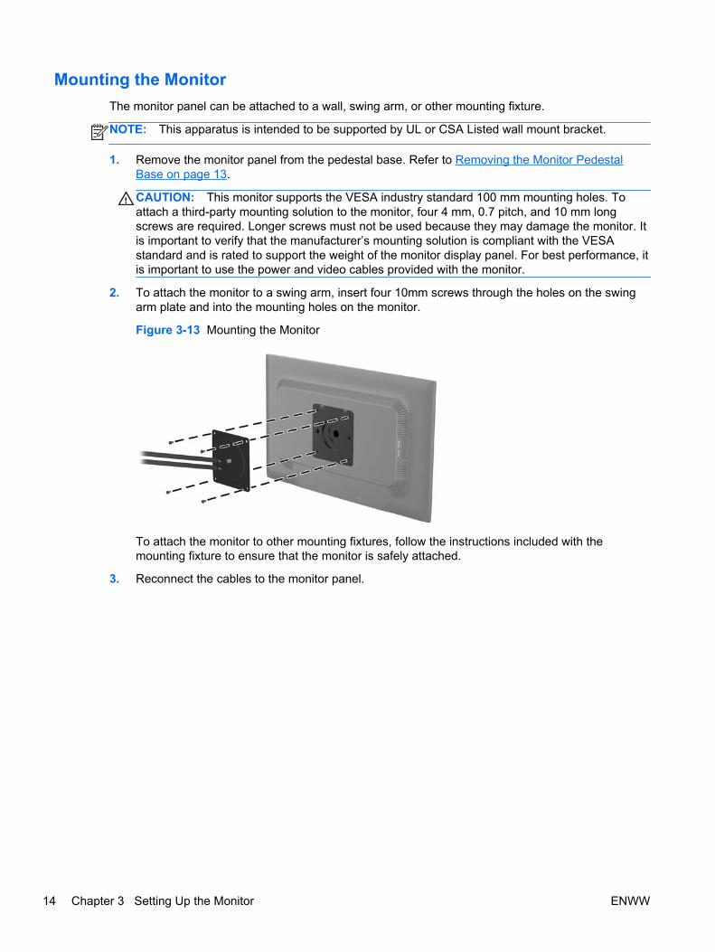
The monitor panel can be attached to a wall, swing arm, or other mounting fixture.
NOTE: This apparatus is intended to be supported by UL or CSA Listed wall mount bracket.
1. Remove the monitor panel from the pedestal base. Refer to Removing the Monitor PedestalBase on page 13.
CAUTION: This monitor supports the VESA industry standard 100 mm mounting holes. Toattach a third-party mounting solution to the monitor, four 4 mm, 0.7 pitch, and 10 mm longscrews are required. Longer screws must not be used because they may damage the monitor. Itis important to verify that the manufacturer’s mounting solution is compliant with the VESAstandard and is rated to support the weight of the monitor display panel. For best performance, itis important to use the power and video cables provided with the monitor.
2. To attach the monitor to a swing arm, insert four 10mm screws through the holes on the swingarm plate and into the mounting holes on the monitor.
Figure 3-13 Mounting the Monitor
To attach the monitor to other mounting fixtures, follow the instructions included with themounting fixture to ensure that the monitor is safely attached.
3. Reconnect the cables to the monitor panel.
14 Chapter 3 Setting Up the Monitor ENWW
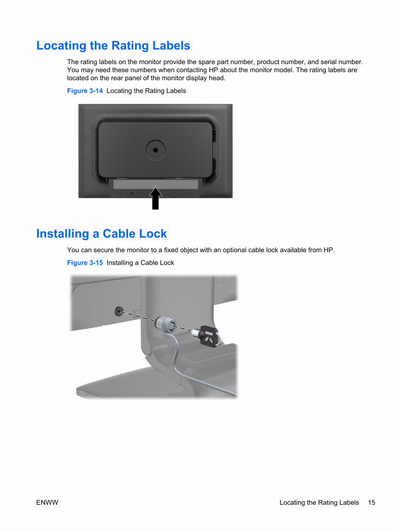
Locating the Rating LabelsThe rating labels on the monitor provide the spare part number, product number, and serial number.You may need these numbers when contacting HP about the monitor model. The rating labels arelocated on the rear panel of the monitor display head.
Figure 3-14 Locating the Rating Labels
Installing a Cable LockYou can secure the monitor to a fixed object with an optional cable lock available from HP.
Figure 3-15 Installing a Cable Lock
ENWW Locating the Rating Labels 15

4 Operating the Monitor
Software and UtilitiesThe CD that comes with the monitor contains files you can install on the computer:
● an .INF (Information) file
● an .ICM (Image Color Matching) file
● auto-adjustment pattern utility
● additional software for the monitor model
NOTE: If the monitor does not include a CD, the .INF and .ICM files can be downloaded from theHP monitors support Web site. See Downloading from the Worldwide Web on page 17 in thischapter.
The Information File
The .INF file defines monitor resources used by Microsoft Windows operating systems to ensuremonitor compatibility with the computer’s graphics adapter.
This monitor is Microsoft Windows Plug and Play compatible and the monitor will work correctlywithout installing the .INF file. Monitor Plug and Play compatibility requires that the computer’sgraphic card is VESA DDC2–compliant and that the monitor connects directly to the graphics card.Plug and Play does not work through separate BNC type connectors or through distribution buffers/boxes.
The Image Color Matching File
The .ICM files are data files that are used in conjunction with graphics programs to provide consistentcolor matching from monitor screen to printer, or from scanner to monitor screen. This file is activatedfrom within graphics programs that support this feature.
NOTE: The ICM color profile is written in accordance with the International Color Consortium (ICC)Profile Format specification.
16 Chapter 4 Operating the Monitor ENWW

Installing the .INF and .ICM FilesAfter you determine that you need to update, you can install the .INF and .ICM files from the CD ordownload them.
Installing from the CD
To install the .INF and .ICM files on the computer from the CD:
1. Insert the CD in the computer CD-ROM drive. The CD menu is displayed.
2. View the Monitor Driver Software Readme file.
3. Select Install Monitor Driver Software.
4. Follow the on-screen instructions.
5. Ensure that the proper resolution and refresh rates appear in the Windows Display control panel.
NOTE: You may need to install the digitally signed monitor .INF and .ICM files manually from theCD in the event of an installation error. Refer to the Monitor Driver Software Readme file on the CD.
Downloading from the Worldwide Web
To download the latest version of .INF and .ICM files from the HP monitors support Web site:
1. Refer to http://www.hp.com/support and select the country region.
2. Follow the links for the monitor to the support page and download page.
3. Ensure the system meets the requirements.
4. Download the software by following the instructions.
ENWW Installing the .INF and .ICM Files 17

Using the Auto-Adjustment FunctionYou can optimize the screen performance for the VGA (analog) input by using the OK/auto button onthe monitor and the auto-adjustment pattern software utility on the CD provided.
Do not use this procedure if the monitor is using a DVI or DisplayPort input. If the monitor is using aVGA (analog) input, this procedure can correct the following image quality conditions:
● Fuzzy or unclear focus
● Ghosting, streaking or shadowing effects
● Faint vertical bars
● Thin, horizontal scrolling lines
● An off-center picture
To use the auto-adjustment feature:
1. Allow the monitor to warm up for 20 minutes before adjusting.
2. Press the OK/auto button on the monitor front panel.
● You can also press the Menu button, then select Image Control > Auto-Adjustment fromthe OSD Main Menu. Refer to Adjusting the Monitor Settings on page 20 in this chapter.
● If the result is not satisfactory, continue with the procedure.
3. Insert the CD in the disc drive. The CD menu is displayed.
4. Select Open Auto-Adjustment Software. The setup test pattern is displayed.
5. Press the OK/auto button on the monitor front panel to produce a stable, centered image.
6. Press the ESC key or any other key on the keyboard to exit the test pattern.
18 Chapter 4 Operating the Monitor ENWW
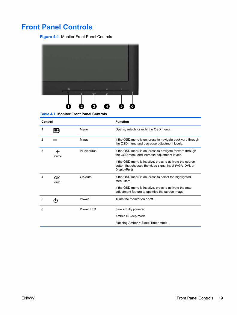
Front Panel ControlsFigure 4-1 Monitor Front Panel Controls
Table 4-1 Monitor Front Panel Controls
Control Function
1 Menu Opens, selects or exits the OSD menu.
2 Minus If the OSD menu is on, press to navigate backward throughthe OSD menu and decrease adjustment levels.
3 Plus/source If the OSD menu is on, press to navigate forward throughthe OSD menu and increase adjustment levels.
If the OSD menu is inactive, press to activate the sourcebutton that chooses the video signal input (VGA, DVI, orDisplayPort)
4 OK/auto If the OSD menu is on, press to select the highlightedmenu item.
If the OSD menu is inactive, press to activate the autoadjustment feature to optimize the screen image.
5 Power Turns the monitor on or off.
6 Power LED Blue = Fully powered.
Amber = Sleep mode.
Flashing Amber = Sleep Timer mode.
ENWW Front Panel Controls 19
Adjusting the Monitor SettingsThe monitor settings can be adjusted from the On-Screen Display (OSD) menu or from the HPDisplay Assistant utility.
NOTE: If there is a problem with the display settings, try resetting the settings to the factory defaultsby opening the OSD and selecting Factory Reset from the OSD menu.
Using the On-Screen Display Menu
Use the On-Screen Display (OSD) to adjust the screen image based on your viewing preferences. Toaccess the OSD, do the following:
1. If the monitor is not already on, press the Power button to turn on the monitor.
2. To access the OSD Menu, press the Menu button on the monitor’s front panel.
3. To navigate through the OSD Menu, press the + (Plus) button on the monitor’s front panel toscroll up, or the – (Minus) button to scroll in reverse.
4. To select an item from the OSD Menu, use the + or – buttons to scroll to and highlight yourselection, then press the OK button to select that function.
5. Adjust the item using the + or – buttons on the front panel to adjust the scale.
6. After adjusting the function, select Save and Return, or Cancel if you don’t want to save thesetting, then select Exit from the Main Menu.
NOTE: If the buttons remain untouched for 10 seconds while displaying a menu, the OSDautomatically saves all changes and exits.
20 Chapter 4 Operating the Monitor ENWW
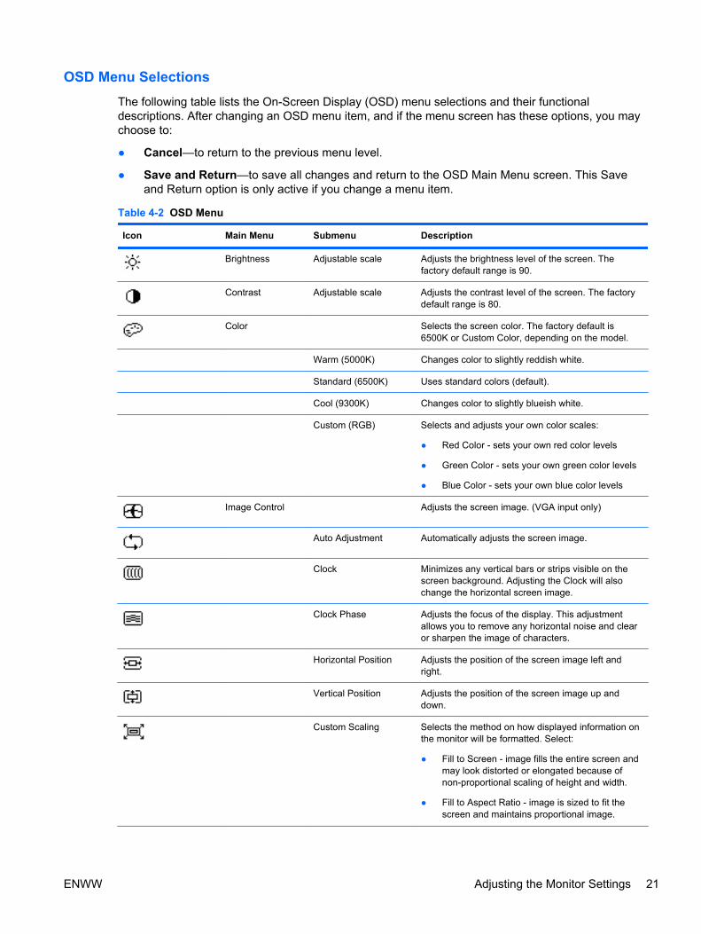
OSD Menu Selections
The following table lists the On-Screen Display (OSD) menu selections and their functionaldescriptions. After changing an OSD menu item, and if the menu screen has these options, you maychoose to:
● Cancel—to return to the previous menu level.
● Save and Return—to save all changes and return to the OSD Main Menu screen. This Saveand Return option is only active if you change a menu item.
Table 4-2 OSD Menu
Icon Main Menu Submenu Description
Brightness Adjustable scale Adjusts the brightness level of the screen. Thefactory default range is 90.
Contrast Adjustable scale Adjusts the contrast level of the screen. The factorydefault range is 80.
Color Selects the screen color. The factory default is6500K or Custom Color, depending on the model.
Warm (5000K) Changes color to slightly reddish white.
Standard (6500K) Uses standard colors (default).
Cool (9300K) Changes color to slightly blueish white.
Custom (RGB) Selects and adjusts your own color scales:
● Red Color - sets your own red color levels
● Green Color - sets your own green color levels
● Blue Color - sets your own blue color levels
Image Control Adjusts the screen image. (VGA input only)
Auto Adjustment Automatically adjusts the screen image.
Clock Minimizes any vertical bars or strips visible on thescreen background. Adjusting the Clock will alsochange the horizontal screen image.
Clock Phase Adjusts the focus of the display. This adjustmentallows you to remove any horizontal noise and clearor sharpen the image of characters.
Horizontal Position Adjusts the position of the screen image left andright.
Vertical Position Adjusts the position of the screen image up anddown.
Custom Scaling Selects the method on how displayed information onthe monitor will be formatted. Select:
● Fill to Screen - image fills the entire screen andmay look distorted or elongated because ofnon-proportional scaling of height and width.
● Fill to Aspect Ratio - image is sized to fit thescreen and maintains proportional image.
ENWW Adjusting the Monitor Settings 21
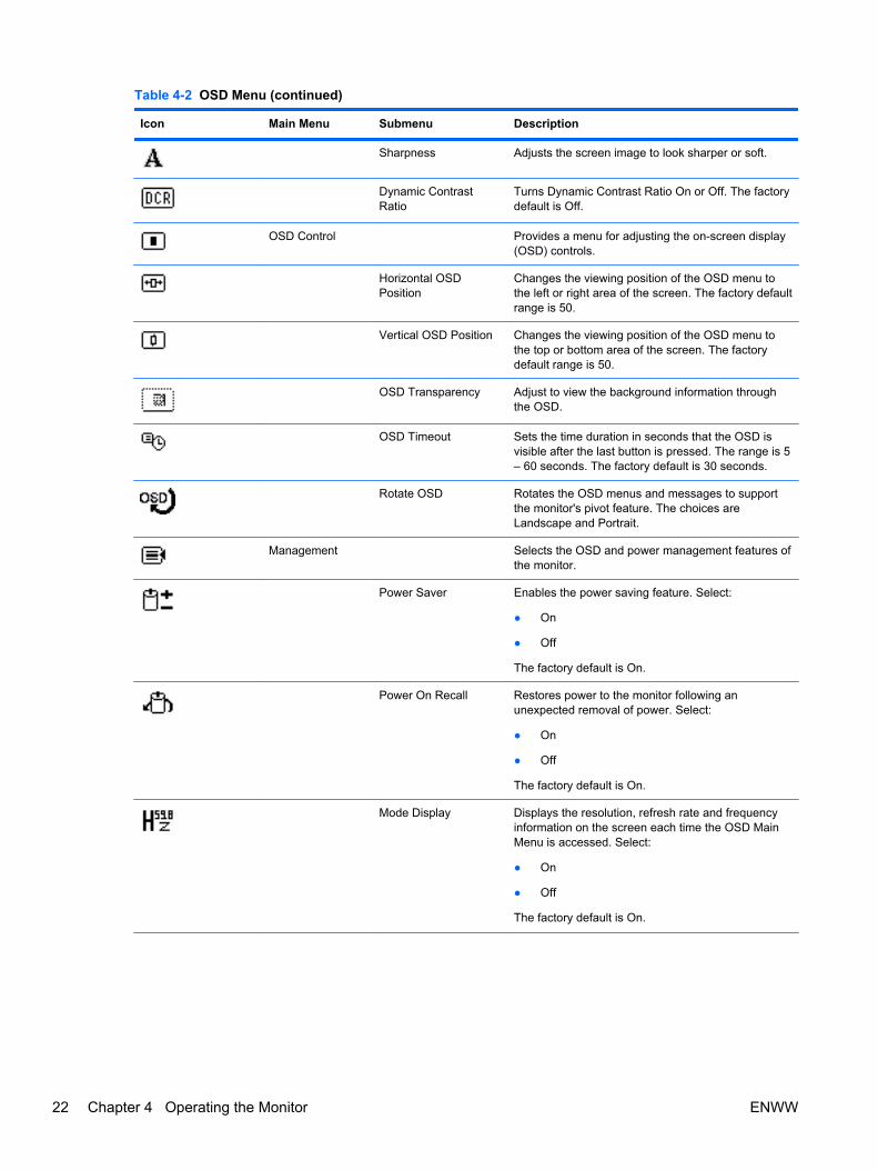
Table 4-2 OSD Menu (continued)
Icon Main Menu Submenu Description
Sharpness Adjusts the screen image to look sharper or soft.
Dynamic ContrastRatio
Turns Dynamic Contrast Ratio On or Off. The factorydefault is Off.
OSD Control Provides a menu for adjusting the on-screen display(OSD) controls.
Horizontal OSDPosition
Changes the viewing position of the OSD menu tothe left or right area of the screen. The factory defaultrange is 50.
Vertical OSD Position Changes the viewing position of the OSD menu tothe top or bottom area of the screen. The factorydefault range is 50.
OSD Transparency Adjust to view the background information throughthe OSD.
OSD Timeout Sets the time duration in seconds that the OSD isvisible after the last button is pressed. The range is 5– 60 seconds. The factory default is 30 seconds.
Rotate OSD Rotates the OSD menus and messages to supportthe monitor's pivot feature. The choices areLandscape and Portrait.
Management Selects the OSD and power management features ofthe monitor.
Power Saver Enables the power saving feature. Select:
● On
● Off
The factory default is On.
Power On Recall Restores power to the monitor following anunexpected removal of power. Select:
● On
● Off
The factory default is On.
Mode Display Displays the resolution, refresh rate and frequencyinformation on the screen each time the OSD MainMenu is accessed. Select:
● On
● Off
The factory default is On.
22 Chapter 4 Operating the Monitor ENWW
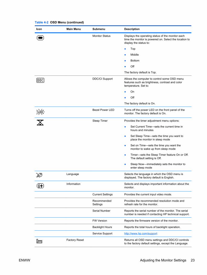
Table 4-2 OSD Menu (continued)
Icon Main Menu Submenu Description
Monitor Status Displays the operating status of the monitor eachtime the monitor is powered on. Select the location todisplay the status to:
● Top
● Middle
● Bottom
● Off
The factory default is Top.
DDC/CI Support Allows the computer to control some OSD menufeatures such as brightness, contrast and colortemperature. Set to:
● On
● Off
The factory default is On.
Bezel Power LED Turns off the power LED on the front panel of themonitor. The factory default is On.
Sleep Timer Provides the timer adjustment menu options:
● Set Current Time—sets the current time inhours and minutes
● Set Sleep Time—sets the time you want toplace the monitor in sleep mode
● Set on Time—sets the time you want themonitor to wake up from sleep mode
● Timer—sets the Sleep Timer feature On or Off.The default setting is Off.
● Sleep Now—immediately sets the monitor toenter sleep mode
Language Selects the language in which the OSD menu isdisplayed. The factory default is English.
Information Selects and displays important information about themonitor.
Current Settings Provides the current input video mode.
RecommendedSettings
Provides the recommended resolution mode andrefresh rate for the monitor.
Serial Number Reports the serial number of the monitor. The serialnumber is needed if contacting HP technical support.
FW Version Reports the firmware version of the monitor.
Backlight Hours Reports the total hours of backlight operation.
Service Support http://www.hp.com/support
Factory Reset Returns all OSD menu settings and DDC/CI controlsto the factory default settings, except the Language.
ENWW Adjusting the Monitor Settings 23
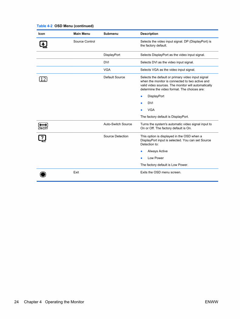
Table 4-2 OSD Menu (continued)
Icon Main Menu Submenu Description
Source Control Selects the video input signal. DP (DisplayPort) isthe factory default.
DisplayPort Selects DisplayPort as the video input signal.
DVI Selects DVI as the video input signal.
VGA Selects VGA as the video input signal.
Default Source Selects the default or primary video input signalwhen the monitor is connected to two active andvalid video sources. The monitor will automaticallydetermine the video format. The choices are:
● DisplayPort
● DVI
● VGA
The factory default is DisplayPort.
Auto-Switch Source Turns the system's automatic video signal input toOn or Off. The factory default is On.
Source Detection This option is displayed in the OSD when aDisplayPort input is selected. You can set SourceDetection to:
● Always Active
● Low Power
The factory default is Low Power.
Exit Exits the OSD menu screen.
24 Chapter 4 Operating the Monitor ENWW
Optimizing Image Performance
Two controls in the on-screen display can be adjusted to improve image performance: Clock andClock Phase.
NOTE: The Clock and Clock Phase controls are adjustable only when using an analog input. Thesecontrols are not adjustable for digital inputs.
The Clock must first be set correctly since the Clock Phase settings are dependent on the main Clocksetting. Use these controls only when the auto-adjustment function does not provide a satisfactoryimage.
● Clock—Increases/decreases the value to minimize any vertical bars or stripes visible on thescreen background.
● Clock Phase—Increases/decreases the value to minimize video flickering or blurring.
NOTE: When using the controls, you will obtain the best results by using the auto-adjustmentpattern software utility provided on the CD.
When adjusting the Clock and Clock Phase values, if the monitor images become distorted, continueadjusting the values until the distortion disappears. To restore the factory settings, select Yes fromthe Factory Reset menu in the on-screen display.
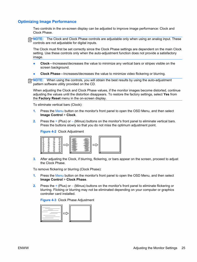
To eliminate vertical bars (Clock):
1. Press the Menu button on the monitor's front panel to open the OSD Menu, and then selectImage Control > Clock.
2. Press the + (Plus) or – (Minus) buttons on the monitor's front panel to eliminate vertical bars.Press the buttons slowly so that you do not miss the optimum adjustment point.
Figure 4-2 Clock Adjustment
3. After adjusting the Clock, if blurring, flickering, or bars appear on the screen, proceed to adjustthe Clock Phase.
To remove flickering or blurring (Clock Phase):
1. Press the Menu button on the monitor's front panel to open the OSD Menu, and then selectImage Control > Clock Phase.
2. Press the + (Plus) or – (Minus) buttons on the monitor's front panel to eliminate flickering orblurring. Flicking or blurring may not be eliminated depending on your computer or graphicscontroller card installed.
Figure 4-3 Clock Phase Adjustment
ENWW Adjusting the Monitor Settings 25
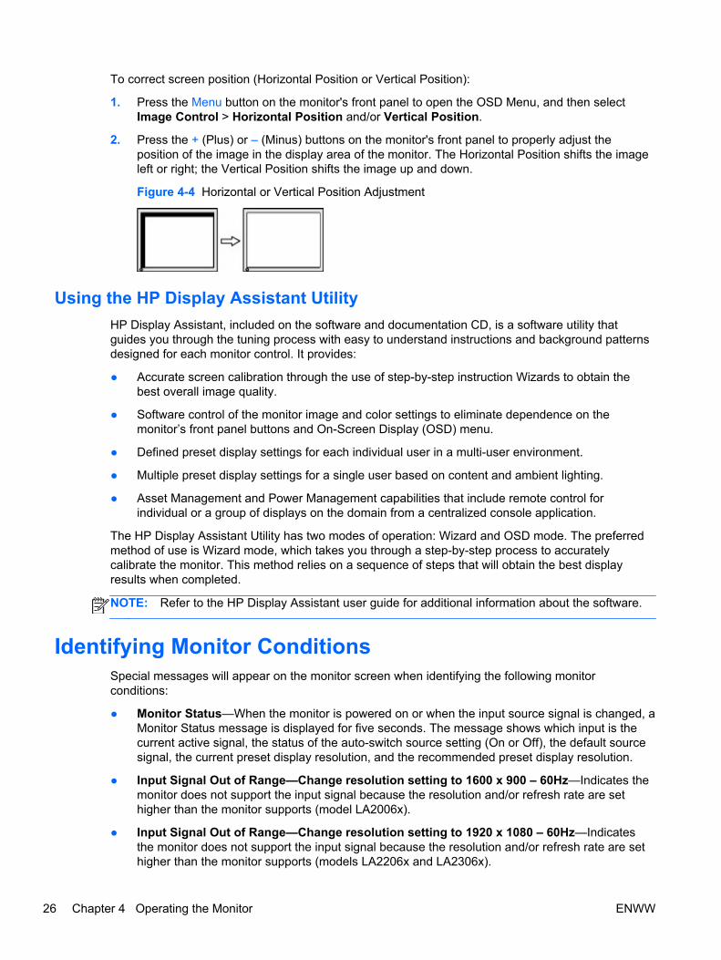
To correct screen position (Horizontal Position or Vertical Position):
1. Press the Menu button on the monitor's front panel to open the OSD Menu, and then selectImage Control > Horizontal Position and/or Vertical Position.
2. Press the + (Plus) or – (Minus) buttons on the monitor's front panel to properly adjust theposition of the image in the display area of the monitor. The Horizontal Position shifts the imageleft or right; the Vertical Position shifts the image up and down.
Figure 4-4 Horizontal or Vertical Position Adjustment
Using the HP Display Assistant Utility
HP Display Assistant, included on the software and documentation CD, is a software utility thatguides you through the tuning process with easy to understand instructions and background patternsdesigned for each monitor control. It provides:
● Accurate screen calibration through the use of step-by-step instruction Wizards to obtain thebest overall image quality.
● Software control of the monitor image and color settings to eliminate dependence on themonitor’s front panel buttons and On-Screen Display (OSD) menu.
● Defined preset display settings for each individual user in a multi-user environment.
● Multiple preset display settings for a single user based on content and ambient lighting.
● Asset Management and Power Management capabilities that include remote control forindividual or a group of displays on the domain from a centralized console application.
The HP Display Assistant Utility has two modes of operation: Wizard and OSD mode. The preferredmethod of use is Wizard mode, which takes you through a step-by-step process to accuratelycalibrate the monitor. This method relies on a sequence of steps that will obtain the best displayresults when completed.
NOTE: Refer to the HP Display Assistant user guide for additional information about the software.
Identifying Monitor ConditionsSpecial messages will appear on the monitor screen when identifying the following monitorconditions:
● Monitor Status—When the monitor is powered on or when the input source signal is changed, aMonitor Status message is displayed for five seconds. The message shows which input is thecurrent active signal, the status of the auto-switch source setting (On or Off), the default sourcesignal, the current preset display resolution, and the recommended preset display resolution.
● Input Signal Out of Range—Change resolution setting to 1600 x 900 – 60Hz—Indicates themonitor does not support the input signal because the resolution and/or refresh rate are sethigher than the monitor supports (model LA2006x).
● Input Signal Out of Range—Change resolution setting to 1920 x 1080 – 60Hz—Indicatesthe monitor does not support the input signal because the resolution and/or refresh rate are sethigher than the monitor supports (models LA2206x and LA2306x).
26 Chapter 4 Operating the Monitor ENWW

● No Source Signal—Indicates the monitor is not receiving a video signal from the PC on themonitor video input connector. Check to determine if the PC or input signal source is off or in thepower saving mode.
● Auto Adjustment in Progress—Indicates the auto-adjustment function is active.
● Monitor Going to Sleep—Indicates the screen display is entering a sleep mode.
● Check Video Cable—Indicates the video cable is not properly connected to the computer.
● OSD Lockout—The OSD can be enabled or disabled by pressing and holding the Menu buttonon the front panel for 10 seconds. If the OSD is locked, the warning message OSD Lockoutdisplays for ten seconds.
◦ If the OSD is locked, press and hold the Menu button for 10 seconds to unlock the OSD.
◦ If the OSD is unlocked, press and hold the Menu button for 10 seconds to lock the OSD.
● Power Button Lockout—Indicates the power button is locked. If the power button is locked, thewarning message Power Button Lockout displays.
◦ If the power button is locked, press and hold the power button for 10 seconds to unlock thepower button function.
◦ If the power button is unlocked, press and hold the power button for 10 seconds to lock outthe power button function.
● Dynamic Contrast Ratio On—Indicates that Dynamic Contrast Ratio has been turned on. Thisoccurs if Dynamic Contrast Ratio is turned on in the Image Control OSD menu.
● Dynamic Contrast Ratio Off—Indicates that Dynamic Contrast Ratio has been turned off. Thisoccurs if Dynamic Contrast Ratio is turned off in the Image Control OSD menu.
● Theft Mode Enabled—Indicates that theft deterrence mode has been activated. Theftdeterrence is an optional feature that can be set up in HP Display Assistant. Theft deterrencemode is triggered if both the power and display cables have been disconnected from themonitor, the monitor is reconnected to a different computer, and the theft deterrence PIN numberis not entered within the elapsed time. When the monitor is in theft deterrence mode, all frontpanel buttons are disabled other than the power button.
Sleep Timer ModeThe Sleep Timer mode is an energy-saving feature that enables you to set a time for the monitor topower on and off at the same time every day. This also extends the life of the backlight bulbs in themonitor. The Sleep Timer has five settings:
● Set Current Time
● Set Sleep Time
● Set On Time
● Timer: On/Off
● Sleep Now
To set the timer:
1. Press the Menu button on the monitor front panel to display the OSD Menu.
2. Scroll down and highlight Management.
3. Press the OK button to select Management.
ENWW Sleep Timer Mode 27

4. Scroll down and highlight and select Sleep Timer > Set Current Time.
NOTE: You must set the current local time before you reset the time for Sleep Time or OnTime. Note that the time is displayed in a 24–hour clock format. For example, 1:15 p.m. isdisplayed as 13 hours 15 minutes.
A power failure or loss of power to the monitor will cause the timer to reset to 00:00. If thisoccurs, you will need to reset the sleep timer mode.
5. Press the OK button once to enter the adjustment mode for hours.
6. Press the - (Minus) or + (Plus) button to adjust the hour.
7. Press the OK button again to enter the time for minutes.
8. Press the - (Minus) or + (Plus) button to adjust the minutes.
9. Press the OK button to lock in the time chosen.
10. After setting the current time, the highlight automatically skips to Set Sleep Time. Repeat steps6 through 9 to set Sleep Time.
11. If you do not want to set Sleep Time, press the OK button twice, then select Save and Returnto exit the menu.
12. After setting Sleep Time, the highlight automatically skips to Set On Time. Repeat steps 6through 9 to set On Time.
13. Set the Timer mode to On to activate the Sleep Timer settings.
14. When you are finished, select Save and Return to exit the menu.
The fifth selection, Sleep Now, turns the monitor backlights off immediately and stays in sleep modeuntil the next On Time activates or a monitor button is pressed.
28 Chapter 4 Operating the Monitor ENWW
A Troubleshooting
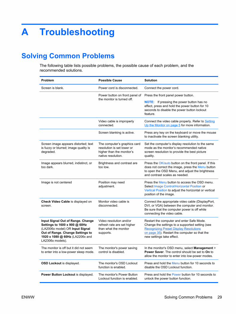
Solving Common ProblemsThe following table lists possible problems, the possible cause of each problem, and therecommended solutions.
Problem Possible Cause Solution
Screen is blank. Power cord is disconnected. Connect the power cord.
Power button on front panel ofthe monitor is turned off.
Press the front panel power button.
NOTE: If pressing the power button has noeffect, press and hold the power button for 10seconds to disable the power button lockoutfeature.
Video cable is improperlyconnected.
Connect the video cable properly. Refer to SettingUp the Monitor on page 5 for more information.
Screen blanking is active. Press any key on the keyboard or move the mouseto inactivate the screen blanking utility.
Screen image appears distorted; textis fuzzy or blurred; image quality isdegraded.
The computer’s graphics cardresolution is set lower orhigher than the monitor’snative resolution.
Set the computer’s display resolution to the samemode as the monitor’s recommended nativescreen resolution to provide the best picturequality.
Image appears blurred, indistinct, ortoo dark.
Brightness and contrast aretoo low.
Press the OK/auto button on the front panel. If thisdoes not correct the image, press the Menu buttonto open the OSD Menu, and adjust the brightnessand contrast scales as needed.
Image is not centered Position may needadjustment.
Press the Menu button to access the OSD menu.Select Image Control/Horizontal Position orVertical Position to adjust the horizontal or verticalposition of the image.
Check Video Cable is displayed onscreen.
Monitor video cable isdisconnected.
Connect the appropriate video cable (DisplayPort,DVI, or VGA) between the computer and monitor.Be sure that the computer power is off whileconnecting the video cable.
Input Signal Out of Range. ChangeSettings to 1600 x 900 @ 60Hz(LA2006x model) OR Input SignalOut of Range. Change Settings to1920 x 1080 @ 60Hz (LA2206x andLA2306x models).
Video resolution and/orrefresh rate are set higherthan what the monitorsupports.
Restart the computer and enter Safe Mode.Change the settings to a supported setting (seeRecognizing Preset Display Resolutionson page 35). Restart the computer so that thenew settings take effect.
The monitor is off but it did not seemto enter into a low-power sleep mode.
The monitor's power savingcontrol is disabled.
In the monitor's OSD menu, select Management >Power Saver. The control should be set to On toallow the monitor to enter into low-power modes.
OSD Lockout is displayed. The monitor's OSD Lockoutfunction is enabled.
Press and hold the Menu button for 10 seconds todisable the OSD Lockout function.
Power Button Lockout is displayed. The monitor's Power ButtonLockout function is enabled.
Press and hold the Power button for 10 seconds tounlock the power button function.
ENWW Solving Common Problems 29

Online Technical SupportFor the online access to technical support information, self-solve tools, online assistance, communityforums of IT experts, broad multivendor knowledge base, monitoring and diagnostic tools, go tohttp://www.hp.com/support.
Preparing to Call Technical SupportIf you cannot solve a problem using the troubleshooting tips in this section, you may need to calltechnical support. Have the following information available when you call:
● Monitor model number
● Monitor serial number
● Purchase date on invoice
● Conditions under which the problem occurred
● Error messages received
● Hardware configuration
● Name and version of the hardware and software you are using
30 Appendix A Troubleshooting ENWW

B Technical Specifications
NOTE: All specifications represent the typical specifications provided by HP's componentmanufacturers; actual performance may vary either higher or lower.
LA2006x ModelTable B-1 LA2006x Specifications
Display
Type
50.8 cm wide screen
TFT LCD
20 inches wide screen
Viewable Image Size 50.8 cm diagonal 20–inch diagonal
Tilt -5 to 30°
Swivel -180 to 180°
Maximum Weight (Unpacked) 5.48 kg 12.1 lbs
Dimensions (include base)
Height (highest position)
Height (lowest position)
Depth
Width
41.8 cm
31.63 cm
21.63 cm
48.36 cm
16.46 inches
12.45 inches
8.52 inches
19.04 inches
Maximum Graphic Resolution 1600 x 900 (60 Hz) analog input
1600 x 900 (60 Hz) digital input
Optimum Graphic Resolution 1600 x 900 (60 Hz) analog input
1600 x 900 (60 Hz) digital input
Text Mode 720 × 400
Dot Pitch 0.2768 (H) × 0.2768 (W) mm
Pixels Per Inch 91.8 PPI
Horizontal Frequency 24 to 83 kHz
Vertical Refresh Rate 50 to 76 Hz
Environmental Requirements Temperature
Operating Temperature
Storage Temperature
5 to 35° C
-20 to 60° C
41 to 95° F
-4 to 140° F
Relative Humidity 20 to 80%
Power Source 100 – 240 VAC 50/60 Hz
ENWW LA2006x Model 31

Table B-1 LA2006x Specifications (continued)
Altitude:
Operating
Storage
0 to 5000 m
0 to 12192 m
0 to 16,400 feet
0 to 40,000 feet
Measured Power Consumption:
Full Power
Typical Settings
Energy Star® Test Methods
Sleep
Switch Off
34.0 watts
29.0 watts
24.5 watts
0.5 watts
0.5 watts
Input Terminal One VGA connector with cable included;one DVI connector with cable included;one DisplayPort connector (cable notincluded)
LA2206x ModelTable B-2 LA2206x Specifications
Display
Type
54.61 cm wide screen
TFT LCD
21.5 inches wide screen
Viewable Image Size 54.61 cm diagonal 22–inch diagonal
Tilt -5 to 30°
Swivel -180 to 180°
Maximum Weight (Unpacked) 6.0 kg 13.24 lbs
Dimensions (include base)
Height (highest position)
Height (lowest position)
Depth
Width
43.87 cm
33.35 cm
22.72 cm
51.8 cm
17.27 inches
13.13 inches
8.94 inches
20.39 inches
Maximum Graphic Resolution 1920 x 1080 (60 Hz) analog input
1920 x 1080 (60 Hz) digital input
Optimum Graphic Resolution 1920 x 1080 (60 Hz) analog input
1920 x 1080 (60 Hz) digital input
Text Mode 720 x 400
Dot Pitch 0.248 (H) x 0.248 (W) mm
Pixels Per Inch 102 PPI
Horizontal Frequency 24 to 94 kHz
Vertical Refresh Rate 50 to 76 Hz
32 Appendix B Technical Specifications ENWW
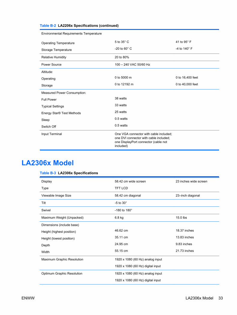
Table B-2 LA2206x Specifications (continued)
Environmental Requirements Temperature
Operating Temperature
Storage Temperature
5 to 35° C
-20 to 60° C
41 to 95° F
-4 to 140° F
Relative Humidity 20 to 80%
Power Source 100 – 240 VAC 50/60 Hz
Altitude:
Operating
Storage
0 to 5000 m
0 to 12192 m
0 to 16,400 feet
0 to 40,000 feet
Measured Power Consumption:
Full Power
Typical Settings
Energy Star® Test Methods
Sleep
Switch Off
38 watts
33 watts
25 watts
0.5 watts
0.5 watts
Input Terminal One VGA connector with cable included;one DVI connector with cable included;one DisplayPort connector (cable notincluded)
LA2306x ModelTable B-3 LA2306x Specifications
Display
Type
58.42 cm wide screen
TFT LCD
23 inches wide screen
Viewable Image Size 58.42 cm diagonal 23–inch diagonal
Tilt -5 to 30°
Swivel -180 to 180°
Maximum Weight (Unpacked) 6.8 kg 15.0 lbs
Dimensions (include base)
Height (highest position)
Height (lowest position)
Depth
Width
46.62 cm
35.11 cm
24.95 cm
55.15 cm
18.37 inches
13.83 inches
9.83 inches
21.73 inches
Maximum Graphic Resolution 1920 x 1080 (60 Hz) analog input
1920 x 1080 (60 Hz) digital input
Optimum Graphic Resolution 1920 x 1080 (60 Hz) analog input
1920 x 1080 (60 Hz) digital input
ENWW LA2306x Model 33
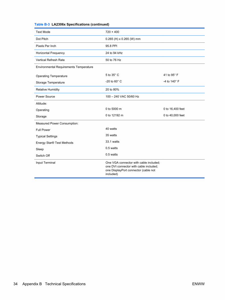
Table B-3 LA2306x Specifications (continued)
Text Mode 720 × 400
Dot Pitch 0.265 (H) x 0.265 (W) mm
Pixels Per Inch 95.8 PPI
Horizontal Frequency 24 to 94 kHz
Vertical Refresh Rate 50 to 76 Hz
Environmental Requirements Temperature
Operating Temperature
Storage Temperature
5 to 35° C
-20 to 60° C
41 to 95° F
-4 to 140° F
Relative Humidity 20 to 80%
Power Source 100 – 240 VAC 50/60 Hz
Altitude:
Operating
Storage
0 to 5000 m
0 to 12192 m
0 to 16,400 feet
0 to 40,000 feet
Measured Power Consumption:
Full Power
Typical Settings
Energy Star® Test Methods
Sleep
Switch Off
40 watts
35 watts
33.1 watts
0.5 watts
0.5 watts
Input Terminal One VGA connector with cable included;one DVI connector with cable included;one DisplayPort connector (cable notincluded)
34 Appendix B Technical Specifications ENWW

Recognizing Preset Display ResolutionsThe display resolutions listed below are the most commonly used modes and are set as factorydefaults. This monitor automatically recognizes these preset modes and they will appear properlysized and centered on the screen.
LA2006x Model
Table B-4 Factory Preset Modes
Preset Pixel Format Horz Freq (kHz) Vert Freq (Hz)
1 640 × 480 31.469 59.94
2 720 × 400 31.469 70.087
3 800 × 600 37.879 60.317
4 1024 × 768 48.363 60.004
5 1280 × 720 45.0 60.0
6 1280 × 1024 63.981 60.02
7 1440 × 900 55.935 59.887
8 1600 × 900 60.0 60.0
Table B-5 High Definition Video Formats
Preset Timing Name Pixel Format Horz Freq (kHz) Vert Freq (Hz)
1 480p 720 × 480 31.469 60
2 576p 720 × 576 31.25 50
3 720p50 1280 × 720 37.5 50
4 720p60 1280 × 720 45 60
LA2206x Model
Table B-6 Factory Preset Modes
Preset Pixel Format Horz Freq (kHz) Vert Freq (Hz)
1 640 × 480 31.469 59.940
2 720 × 400 31.469 70.087
3 800 × 600 37.879 60.317
4 1024 × 768 48.363 60.004
5 1280 × 720 45.00 59.94
6 1280 × 1024 63.981 60.02
7 1440 × 900 55.935 59.887
ENWW Recognizing Preset Display Resolutions 35
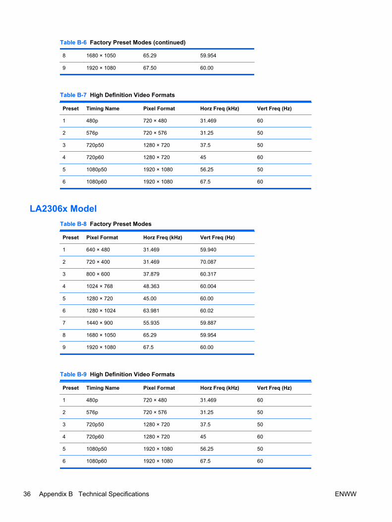
Table B-6 Factory Preset Modes (continued)
8 1680 × 1050 65.29 59.954
9 1920 × 1080 67.50 60.00
Table B-7 High Definition Video Formats
Preset Timing Name Pixel Format Horz Freq (kHz) Vert Freq (Hz)
1 480p 720 × 480 31.469 60
2 576p 720 × 576 31.25 50
3 720p50 1280 × 720 37.5 50
4 720p60 1280 × 720 45 60
5 1080p50 1920 × 1080 56.25 50
6 1080p60 1920 × 1080 67.5 60
LA2306x Model
Table B-8 Factory Preset Modes
Preset Pixel Format Horz Freq (kHz) Vert Freq (Hz)
1 640 × 480 31.469 59.940
2 720 × 400 31.469 70.087
3 800 × 600 37.879 60.317
4 1024 × 768 48.363 60.004
5 1280 × 720 45.00 60.00
6 1280 × 1024 63.981 60.02
7 1440 × 900 55.935 59.887
8 1680 × 1050 65.29 59.954
9 1920 × 1080 67.5 60.00
Table B-9 High Definition Video Formats
Preset Timing Name Pixel Format Horz Freq (kHz) Vert Freq (Hz)
1 480p 720 × 480 31.469 60
2 576p 720 × 576 31.25 50
3 720p50 1280 × 720 37.5 50
4 720p60 1280 × 720 45 60
5 1080p50 1920 × 1080 56.25 50
6 1080p60 1920 × 1080 67.5 60
36 Appendix B Technical Specifications ENWW

Entering User ModesThe video controller signal may occasionally call for a mode that is not preset if:
● You are not using a standard graphics adapter.
● You are not using a preset mode.
It this occurs, you may need to readjust the parameters of the monitor screen by using the on-screendisplay. Your changes can be made to any or all of these modes and saved in memory. The monitorautomatically stores the new setting, then recognizes the new mode just as it does a preset mode. Inaddition to the factory preset modes, there are at least 10 user modes that can be entered andstored.
Energy Saver FeatureThe monitors support a reduced power state. The reduced power state will be entered into if themonitor detects the absence of either the horizontal sync signal and/or the vertical sync signal. Upondetecting the absence of these signals, the monitor screen is blanked, the backlight is turned off, andthe power light is turned amber. When the monitor is in the reduced power state, the monitor willutilize .5 watts of power. There is a brief warm up period before the monitor will return to its normaloperating mode.
Refer to the computer manual for instructions on setting energy saver features (sometimes calledpower management features).
NOTE: The above power saver feature only works when connected to computers that have energysaver features.
By selecting the settings in the monitor's Energy Saver utility, you can also program the monitor toenter into the reduced power state at a predetermined time. When the monitor's Energy Saver utilitycauses the monitor to enter the reduced power state, the power light blinks amber.
ENWW Entering User Modes 37

C Agency Regulatory Notices
Federal Communications Commission NoticeThis equipment has been tested and found to comply with the limits for a Class B digital device,pursuant to Part 15 of the FCC Rules. These limits are designed to provide reasonable protectionagainst harmful interference in a residential installation. This equipment generates, uses, and canradiate radio frequency energy and, if not installed and used in accordance with the instructions, maycause harmful interference to radio communications. However, there is no guarantee that interferencewill not occur in a particular installation. If this equipment does cause harmful interference to radio ortelevision reception, which can be determined by turning the equipment off and on, the user isencouraged to try to correct the interference by one or more of the following measures:
● Reorient or relocate the receiving antenna.
● Increase the separation between the equipment and the receiver.
● Connect the equipment into an outlet on a circuit different from that to which the receiver isconnected.
● Consult the dealer or an experienced radio or television technician for help.
Modifications
The FCC requires the user to be notified that any changes or modifications made to this device thatare not expressly approved by Hewlett Packard Company may void the user's authority to operate theequipment.
Cables
Connections to this device must be made with shielded cables with metallic RFI/EMI connector hoodsto maintain compliance with FCC Rules and Regulations.
Declaration of Conformity for Products Marked with theFCC Logo (United States Only)
This device complies with Part 15 of the FCC Rules. Operation is subject to the following twoconditions:
1. This device may not cause harmful interference.
2. This device must accept any interference received, including interference that may causeundesired operation.
For questions regarding the product, contact:
Hewlett Packard Company
P. O. Box 692000, Mail Stop 530113
Houston, Texas 77269-2000
Or, call 1-800-HP-INVENT (1-800 474-6836)
38 Appendix C Agency Regulatory Notices ENWW

For questions regarding this FCC declaration, contact:
Hewlett Packard Company
P. O. Box 692000, Mail Stop 510101
Houston, Texas 77269-2000
Or, call (281) 514-3333
To identify this product, refer to the Part, Series, or Model number found on the product.
Canadian NoticeThis Class B digital apparatus meets all requirements of the Canadian Interference-CausingEquipment Regulations.
Avis CanadienCet appareil numérique de la classe B respecte toutes les exigences du Règlement sur le matérielbrouilleur du Canada.
European Union Regulatory NoticeProducts bearing the CE marking comply with the following EU Directives:
● Low Voltage Directive 2006/95/EC
● EMC Directive 2004/108/EC
● Ecodesign Directive 2009/125/EC, where applicable
CE compliance of this product is valid if powered with the correct CE-marked AC adapter provided byHP.
Compliance with these directives implies conformity to applicable harmonized European standards(European Norms) that are listed in the EU Declaration of Conformity issued by HP for this product orproduct family and available (in English only) either within the product documentation or at thefollowing web site: http://www.hp.eu/certificates (type the product number in the search field).
The compliance is indicated by one of the following conformity markings placed on the product:
For non-telecommunications products and for EUharmonized telecommunications products, suchas Bluetooth® within power class below 10mW.
For EU non-harmonized telecommunicationsproducts (If applicable, a 4-digit notified bodynumber is inserted between CE and !).
Please refer to the regulatory label provided on the product.
The point of contact for regulatory matters is: Hewlett-Packard GmbH, Dept./MS: HQ-TRE,Herrenberger Strasse 140, 71034 Boeblingen, GERMANY.
ENWW Canadian Notice 39

German Ergonomics NoticeHP products which bear the “GS” approval mark, when forming part of a system comprising HP brandcomputers, keyboards and monitors that bear the “GS” approval mark, meet the applicable ergonomicrequirements. The installation guides included with the products provide configuration information.
Japanese Notice
Korean Notice
Power Cord Set RequirementsThe monitor power supply is provided with Automatic Line Switching (ALS). This feature allows themonitor to operate on input voltages between 100–120V or 200–240V.
The power cord set (flexible cord or wall plug) received with the monitor meets the requirements foruse in the country where you purchased the equipment.
If you need to obtain a power cord for a different country, you should purchase a power cord that isapproved for use in that country.
The power cord must be rated for the product and for the voltage and current marked on the product'selectrical ratings label. The voltage and current rating of the cord should be greater than the voltageand current rating marked on the product. In addition, the cross-sectional area of the wire must be aminimum of 0.75 mm² or 18 AWG, and the length of the cord must be between 6 feet (1.8 m) and 12feet (3.6 m). If you have questions about the type of power cord to use, contact an authorized HPservice provider.
A power cord should be routed so that it is not likely to be walked on or pinched by items placed uponit or against it. Particular attention should be paid to the plug, electrical outlet, and the point where thecord exits from the product.
Japanese Power Cord Requirements
For use in Japan, use only the power cord received with this product.
CAUTION: Do not use the power cord received with this product on any other products.
40 Appendix C Agency Regulatory Notices ENWW

Product Environmental Notices
ENERGY STAR® Qualification
HP Displays marked with the ENERGY STAR® certification mark meet the requirements of the U.S.Environmental Protection Agency (EPA) ENERGY STAR® program. The EPA ENERGY STAR®certification mark does not imply endorsement by the EPA. As an ENERGY STAR® Partner, HewlettPackard Company has determined that this product meets the ENERGY STAR® programrequirements for display energy efficiency.
The following ENERGY STAR® certification mark appears on all ENERGY STAR® qualified displays:
The ENERGY STAR® program specifications for displays and computers were created by the EPA topromote energy efficiency and reduce air pollution through more energy-efficient equipment inhomes, offices, and factories. One way products achieve this goal is by using the Microsoft Windowspower management feature to reduce power consumption when the product is not in use.
The power management feature enables the computer to initiate a low-power or “sleep” mode after aperiod of user inactivity. When used with an external ENERGY STAR® qualified display, this featurealso supports similar power management features for the display. To take advantage of thesepotential energy savings, users should use the default power management settings that are providedwith ENERGY STAR qualified computers and displays. The default power management settings onENERGY STAR® qualified computers are preset to behave in the following ways when the system isoperating on AC power:
● Turn off an external display after 15 minutes of user inactivity
● Initiate a low power sleep mode for the computer after 30 minutes of user inactivity
ENERGY STAR® qualified computers exit the low power sleep mode and ENERGY STAR® qualifieddisplays resume operation when the user resumes use of the computer. Examples include the userpressing the power/sleep button, receiving an input signal from an input device, receiving an inputsignal from a network connection with the Wake On LAN (WOL) feature enabled, etc.
Additional information on the ENERGY STAR® program, its environmental benefits and the potentialenergy and financial savings of the power management feature can be found on the EPA ENERGYSTAR® Power Management Web site at http://www.energystar.gov/powermanagement.
Materials Disposal
Some HP LCD monitors contain mercury in the fluorescent lamps that might require special handlingat end-of-life.
Disposal of this material can be regulated because of environmental considerations. For disposal orrecycling information, contact the local authorities or the Electronic Industries Alliance (EIA)http://www.eiae.org.
ENWW Product Environmental Notices 41

Disposal of Waste Equipment by Users in Private Household in theEuropean Union
This symbol on the product or on its packaging indicates that this product must not be disposed ofwith your household waste. Instead, it is your responsibility to dispose of your waste equipment byhanding it over to a designated collection point for the recycling or waste electrical and electronicequipment. The separate collection and recycling of your waste equipment at the time of disposal willhelp to conserve natural resources and ensure that it is recycled in a manner that protects humanhealth and the environment. For more information about where you can drop off your wasteequipment for recycling, please contact the local city office, the household waste disposal service orthe shop where you purchased the product.
HP Recycling Program
HP encourages customers to recycle used electronic hardware, HP original print cartridges, andrechargeable batteries. For more information about recycling programs, go to http://www.hp.com/recycle.
Chemical Substances
HP is committed to providing our customers with information about the chemical substances in ourproducts as needed to comply with legal requirements such as REACH (Regulation EC No1907/2006 of the European Parliament and Council). A chemical information report for this productcan be found at http://www.hp.com/go/reach.
Restriction of Hazardous Substances (RoHS)
A Japanese regulatory requirement, defined by specification JIS C 0950, 2005, mandates thatmanufacturers provide Material Content Declarations for certain categories of electronic productsoffered for sale after July 1, 2006. To view the JIS C 0950 material declaration for this product, visithttp://www.hp.com/go/jisc0950.
42 Appendix C Agency Regulatory Notices ENWW

Turkey EEE Regulation
In Conformity with the EEE Regulation
EEE Yönetmeliğine Uygundur
ENWW Product Environmental Notices 43

D LCD Monitor Quality and Pixel Policy
The TFT monitor uses high-precision technology, manufactured according to HP standards, toguarantee trouble-free performance. Nevertheless, the display may have cosmetic imperfections thatappear as small bright or dark spots. This is common to all LCD displays used in products supplied byall vendors and is not specific to the HP LCD. These imperfections are caused by one or moredefective pixels or sub-pixels.
● A pixel consists of one red, one green, and one blue sub-pixel.
● A defective whole pixel is always turned on (a bright spot on a dark background), or it is alwaysoff (a dark spot on a bright background). The first is the more visible of the two.
● A defective sub-pixel (dot defect) is less visible than a defective whole pixel and is small andonly visible on a specific background.
To locate defective pixels, the monitor should be viewed under normal operating conditions, in normaloperating mode at a supported resolution and refresh rate, from a distance of approximately 50 cm(20 in).
HP expects that, over time, the industry will continue to improve its ability to produce LCDs with fewercosmetic imperfections and HP will adjust guidelines as improvements are made.
44 Appendix D LCD Monitor Quality and Pixel Policy ENWW