HP 4284A PRECISION L CR METER - Wikis · Do not op erate the instrumen t in the presence of ammable...
460
Transcript of HP 4284A PRECISION L CR METER - Wikis · Do not op erate the instrumen t in the presence of ammable...

HP 4284A PRECISION LCR METER
OPERATION MANUAL
(Including Option 001, 002, 006, 201, 202, 301)
SERIAL NUMBERS
This manual applies directly to instruments with the serial numberpre�x of 2940J02283,02285 and above, and whose ROM-based�rmware is version 01.20. For additional important information aboutserial numbers, read \Serial Number" in Chapter 9 of this OperationManual.
HP Part No. 04284-90040
Printed in JAPAN August 1998
Sixth Edition

Notice The information contained in this document is subject to changewithout notice.
This document contains proprietary information which is protectedby copyright. All rights are reserved. No part of this documentmay be photocopied, reproduced, or translated to another languagewithout the prior written consent of the Hewlett-Packard Company.
Hewlett-Packard Japan, LTD.Kobe Instrument Division1-3-2, Murotani, Nishi-ku, Kobe-shi,Hyogo, 651-2241 Japan
c Copyright 1988,1991,1994,1996,1998 Hewlett-Packard Japan, LTD.

Manual PrintingHistory
The manual printing date and part number indicate its currentedition. The printing date changes when a new edition is printed.(Minor corrections and updates which are incorporated at reprint donot cause the date to change.) The manual part number changeswhen extensive technical changes are incorporated.
December 1988 : : : : : : : : : : : : : : : : : : : : : : : : : : : : : : : : : :First Edition
April 1991 : : : : : : : : : : : : : : : : : : : : : : : : : : : : : : : : : : : : :Second Edition
December 1991 : : : : : : : : : : : : : : : : : : : : : : : : : : : : : : : : :Third Edition
March 1994 : : : : : : : : : : : : : : : : : : : : : : : : : : : : : : : : : : : :Fourth Edition
December 1996 : : : : : : : : : : : : : : : : : : : : : : : : : : : : : : : : : :Fifth Edition
August 1998 : : : : : : : : : : : : : : : : : : : : : : : : : : : : : : : : : : : : Sixth Edition
iii

Safety Summary The following general safety precautions must be observed during allphases of operation, service, and repair of this instrument. Failureto comply with these precautions or with speci�c WARNINGS
elsewhere in this manual may impair the protection provided bythe equipment. In addition it violates safety standards of design,manufacture, and intended use of the instrument.The Hewlett-Packard Company assumes no liability for the customer's
failure to comply with these requirements.
Note HP 4284A complies with INSTALLATION CATEGORY II andPOLLUTION DEGREE 2 in IEC1010-1.HP 4284A is INDOOR USEproduct.
Note LEDs in this product are Class 1 in accordance with IEC825-1.
CLASS 1 LED PRODUCT
Ground The Instrument To avoid electric shock hazard, the instrument chassis and cabinetmust be connected to a safety earth ground by the supplied powercable with earth blade.
DO NOT Operate In AnExplosive Atmosphere
Do not operate the instrument in the presence of ammable gasses orfumes. Operation of any electrical instrument in such an environmentconstitutes a de�nite safety hazard.
Keep Away From LiveCircuits
Operating personnel must not remove instrument covers. Componentreplacement and internal adjustments must be made by quali�edmaintenance personnel. Do not replace components with the powercable connected. Under certain conditions, dangerous voltages mayexist even with the power cable removed. To avoid injuries, alwaysdisconnect power and discharge circuits before touching them.
DO NOT Service OrAdjust Alone
Do not attempt internal service or adjustment unless another person,capable of rendering �rst aid and resuscitation, is present.
DO NOT SubstituteParts Or Modify
Instrument
Because of the danger of introducing additional hazards, do notinstall substitute parts or perform unauthorized modi�cations to theinstrument. Return the instrument to a Hewlett-Packard Sales andService O�ce for service and repair to ensure that safety features aremaintained.
iv

Dangerous ProcedureWarnings
Warnings , such as the example below, precede potentially dangerousprocedures throughout this manual. Instructions contained in thewarnings must be followed.
Warning Dangerous voltages, capable of causing death, are present in this
instrument. Use extreme caution when handling, testing, and adjusting
this instrument.
Safety Symbols General de�nitions of safety symbols used on equipment or inmanuals are listed below.
Instruction manual symbol: the product is markedwith this symbol when it is necessary for the user torefer to the instruction manual.
Alternating current.
Direct current.
On (Supply).
O� (Supply).
In position of push-button switch.
Out position of push-button switch.
Frame (or chassis) terminal. A connection to theframe (chassis) of the equipment which normallyinclude all exposed metal structures.
This Warning sign denotes a hazard. It callsattention to a procedure, practice, condition or thelike, which, if not correctly performed or adhered to,could result in injury or death to personnel.
This Caution sign denotes a hazard. It callsattention to a procedure, practice, condition or thelike, which, if not correctly performed or adhered to,could result in damage to or destruction of part or allof the product.
Note denotes important information. It callsattention to a procedure, practice, condition or thelike, which is essential to highlight.
A�xed to product containing static sensitive devicesuse anti-static handling procedures to preventelectrostatic discharge damage to component.
v

How To Use ThisManual
This manual, the Operation Manual for the HP 4284A PrecisionLCR Meter, contains ten chapters plus appendixes, organized for theconvenience of the �rst time user. After you receive your HP 4284A,begin with Chapter 1.
Chapter 1Getting Started
Chapter 1 provides unpacking, initial inspection, and preparationinformation necessary for you to know before you apply AC power.
Chapter 2Overview
Chapter 2 provides information including a product overview and atour of the front panel, which will help you to quickly learn how tooperate the HP 4284A.
Chapter 3DISPLAY FORMAT
Chapter 3 provides detailed information for the display format andmeasurement function, corresponding to �DISPLAY FORMAT� menu key.
Chapter 4MEAS SETUP
Chapter 4 provides detailed information for the measurementcondition setup, corresponding to �MEAS SETUP� menu key.
Chapter 5CATALOG/SYSTEMCONFIGURATION
Chapter 5 provides detailed information for the internal/externalmemory and system con�guration catalog of the HP 4284A,corresponding to �CATALOG/SYSTEM� menu key.
Chapter 6Measurement Basics
Chapter 6 provides the basic measurement procedure with thegeneral impedance theory and measurement techniques, and practicalmeasurement examples.
Chapter 7Remote Control
Chapter 7 provides information to control the HP 4284A using theHP-IB interface.
Chapter 8Command Reference
Chapter 8 provides detailed information for each of the HP 4284AHP-IB commands.
Chapter 9General Information
Chapter 9 provides the speci�cations, rack mount/handle kitinstallation, and other general information on the HP 4284A.
Chapter 10Performance Test
Chapter 10 provides the performance tests for the HP 4284A usedfor incoming inspection and veri�cation that your instrument iscompletely calibrated.
vi

Appendix AManual Changes
Appendix A contains Manual Changes and provides informationfor using this manual with an HP 4284A manufactured before theprinting date of the manual.
Appendix BError and Warning
Messages
Appendix B lists the HP 4284A's error and warning messages withbrief descriptions and solutions and the system messages.
Appendix CInitial Settings and
System Memory
Appendix C lists the HP 4284A's initial settings and functions whosestatus is stored in internal system memory.
Appendix DCorrection Data
Appendix D provides information about the relationship between thetest frequency and the correction data.
Appendix EWrite Protection
Appendix E provides the procedure for write protecting all of thestored data in the HP 4284A's memory card and internal EEPROMmemory.
Appendix FTest Frequency Points
Appendix F lists all available test frequency points from 1 kHz to 1MHz.
Appendix GTransient States
Caused byMeasurement Condition
Changes
Appendix G describes the measurement condition changes whichcause the transient states, and lists the delay times required forvarious transient states.
TypefaceConventions
Bold Boldface type is used when a term is de�ned.For example: icons are symbols.
Italics Italic type is used for emphasis and for titlesof manuals and other publications.
Italic type is also used for keyboard entrieswhen a name or a variable must be typed inplace of the words in italics. For example:copy �lename means to type the word copy,to type a space, and then to type the name ofa �le such as file1.
Computer Computer font is used for on-screen promptsand messages.
�HARDKEYS� Labeled keys on the instrument front panelare enclosed in � �.
vii

NNNNNNNNNNNNNNNNNNNNNNNNNNSOFTKEYS Softkeys located to the right of the Liquid
Crystal Display (LCD) are enclosed inNNNNN.
Certification Hewlett-Packard Company certi�es that this product metits published speci�cations at the time of shipment from thefactory. Hewlett-Packard further certi�es that its calibrationmeasurements are traceable to the United States National Instituteof Standards and Technology (nist), to the extent allowed by theInstitute's calibration facility, or to the calibration facilities of otherInternational Standards Organization members.
Warranty This Hewlett-Packard instrument product is warranted againstdefects in material and workmanship for a period of one year fromthe date of shipment, except that in the case of certain componentslisted in \Components not Covered by Warranty" in Chapter 9 ofthis manual, the warranty shall be for the speci�ed period. Duringthe warranty period, Hewlett-Packard Company will, at its option,either repair or replace products which prove to be defective.
For warranty service or repair, this product must be returned to aservice facility designated by HP. Buyer shall prepay shipping chargesto HP and HP shall pay shipping charges to return the product toBuyer. However, Buyer shall pay all shipping charges, duties, andtaxes for products returned to HP from another country.
HP warrants that its software and �rmware designated by HP for usewith an instrument will execute its programming instruction whenproperty installed on that instrument. HP does not warrant thatthe operation of the instrument, or software, or �rmware will beuninterrupted or error free.
viii

Limitation ofWarranty
The foregoing warranty shall not apply to defects resulting fromimproper or inadequate maintenance by Buyer, Buyer-suppliedsoftware or interfacing, unauthorized modi�cation or misuse,operation outside of the environmental speci�cations for the product,or improper site preparation or maintenance.
No other warranty is expressed or implied. HP speci�cally disclaims
the implied warranties of merchantability and �tness for a particular
purpose.
Exclusive Remedies The remedies provided herein are buyer's sole and exclusive remedies.
HP shall not be liable for any direct, indirect, special, incidental, or
consequential damages, whether based on contract, tort, or any other
legal theory.
Assistance Product maintenance agreements and other customer assistanceagreements are available for Hewlett-Packard products.
For any assistance, contact your nearest Hewlett-Packard Sales andService O�ce. Addresses are provided at the back of this manual.
ix


Contents
1. Installation and Set Up Guide
Incoming Inspection . . . . . . . . . . . . . . 1-1Power Requirements . . . . . . . . . . . . . . 1-2Power Cable . . . . . . . . . . . . . . . . . 1-2
Line Voltage and Fuse Selection . . . . . . . . . 1-4Line Voltage Selection . . . . . . . . . . . . . 1-4
Fuse Selection . . . . . . . . . . . . . . 1-4
Operation Environment . . . . . . . . . . . . . 1-5Electromagnetic Compatibility . . . . . . . . . . 1-5Ventilation Requirements . . . . . . . . . . . . 1-6Instruction for Cleaning . . . . . . . . . . . . . 1-6Rack/Handle Installation . . . . . . . . . . . . 1-6Option 907 Handle Kit . . . . . . . . . . . . 1-7Installing the Handle . . . . . . . . . . . . 1-7
Option 908 Rack Flange Kit . . . . . . . . . . 1-7Mounting the Rack . . . . . . . . . . . . . 1-7
Option 909 Rack Flange & Handle Kit . . . . . 1-8Mounting the Handle and Rack . . . . . . . 1-8
2. Overview
Introduction . . . . . . . . . . . . . . . . . . 2-1Product Introduction . . . . . . . . . . . . . . 2-1A Tour of the Front Panel . . . . . . . . . . . 2-2(1) LINE On/O� . . . . . . . . . . . . . . 2-2(2) LCD . . . . . . . . . . . . . . . . . . 2-2(3) SOFTKEYs . . . . . . . . . . . . . . 2-2(4) MENU Keys . . . . . . . . . . . . . . 2-2(5) CURSOR Keys . . . . . . . . . . . . . 2-3(6) ENTRY Keys . . . . . . . . . . . . . . 2-3(7) HP-IB Status Indicators . . . . . . . . . 2-3(8) �LCL� Key . . . . . . . . . . . . . . . . 2-3(9) �TRIGGER� Key . . . . . . . . . . . . . . 2-3(10) MEMORY Card Slot and UNLOCK Button 2-3(11) �DC BIAS� Key . . . . . . . . . . . . . 2-3(12) CONTRAST Control Knob . . . . . . . 2-4
(13) UNKNOWN Terminals . . . . . . . 2-4
(14) FRAME Terminal . . . . . . . . . . . 2-4A Tour of the Rear Panel . . . . . . . . . . . 2-4(1) HP-IB Interface Connector . . . . . . . . 2-5(2) Interface Connectors . . . . . . . . . . . 2-5
Contents-1

(3) INT DC BIAS MONITOR Connector . . . 2-5(4) EXT TRIGGER Connector . . . . . . . . 2-5(5) �LINE Input Receptacle . . . . . . . . . 2-6
(6) �LINE Fuse Holder . . . . . . . . 2-6
(7) �LINE VOLTAGE SELECTOR . . . . . 2-6Display . . . . . . . . . . . . . . . . . . . . 2-7Display Area De�nition . . . . . . . . . . . . 2-7Display Page Area . . . . . . . . . . . . . 2-7System Menu Field . . . . . . . . . . . . . 2-7Comment Line Area . . . . . . . . . . . . 2-7Softkey Area . . . . . . . . . . . . . . . . 2-8Measurement Data/Conditions Area . . . . . 2-8Input Line Area . . . . . . . . . . . . . . 2-8System Message Area . . . . . . . . . . . . 2-8
MENU keys and Display Page . . . . . . . . . 2-9DISPLAY FORMAT MENU key . . . . . . . 2-9MEAS SETUP MENU key . . . . . . . . . 2-9CATALOG/SYSTEM menu key . . . . . . . 2-10
Summary of Pages . . . . . . . . . . . . . . 2-11MEAS DISPLAY (under �DISPLAY FORMAT�) . . 2-11BIN No. DISPLAY (under �DISPLAY FORMAT�) . 2-11BIN COUNT DISPLAY (under �DISPLAY FORMAT�) 2-11LIST SWEEP DISPLAY (under �DISPLAY FORMAT�) 2-11MEAS SETUP (under �MEAS SETUP�) . . . . . 2-11CORRECTION (under �MEAS SETUP�) . . . . . 2-11LIMIT TABLE SETUP (under �MEAS SETUP�) . 2-12LIST SWEEP SETUP (under �MEAS SETUP�) . . 2-12CATALOG (under �CATALOG/SYSTEM�) . . . . . 2-12SYSTEM CONFIG (under �CATALOG/SYSTEM�) . 2-12SELF TEST (under �CATALOG/SYSTEM�) . . . . 2-12
Basic Operation . . . . . . . . . . . . . . . . 2-16
3. DISPLAY FORMAT Menu
Introduction . . . . . . . . . . . . . . . . . . 3-1MEAS DISPLAY Page . . . . . . . . . . . . . 3-1Measurement Function . . . . . . . . . . . . 3-4Description . . . . . . . . . . . . . . . . 3-4Front Panel Operation for Setting the
Measurement Function . . . . . . . . . . 3-5Measurement Range . . . . . . . . . . . . . 3-6Description . . . . . . . . . . . . . . . . 3-6Front Panel Operation for Setting the
Measurement Range . . . . . . . . . . . 3-9Test Frequency . . . . . . . . . . . . . . . . 3-10Description . . . . . . . . . . . . . . . . 3-10Front Panel Operation for Setting the Test
Frequency . . . . . . . . . . . . . . . 3-11Oscillator Level . . . . . . . . . . . . . . . 3-12Description . . . . . . . . . . . . . . . . 3-12
Contents-2

Front Panel Operation for Setting the OscillatorLevel . . . . . . . . . . . . . . . . . 3-13
DC Bias . . . . . . . . . . . . . . . . . . . 3-14Description . . . . . . . . . . . . . . . . 3-14Front Panel Operation for Setting the DC Bias . 3-16
Integration Time . . . . . . . . . . . . . . . 3-17Description . . . . . . . . . . . . . . . . 3-17Front Panel Operation for Setting the Integration
Time . . . . . . . . . . . . . . . . . 3-17System Menu . . . . . . . . . . . . . . . . 3-18Load/Store Function . . . . . . . . . . . . 3-18Fixed Decimal Point Function . . . . . . . . 3-20Printer Function . . . . . . . . . . . . . . 3-20Keylock Function . . . . . . . . . . . . . . 3-23
BIN No. DISPLAY Page . . . . . . . . . . . . 3-23Comparator Function ON/OFF . . . . . . . . 3-25Description . . . . . . . . . . . . . . . . 3-25Front Panel Operation for Setting the Comparator
Function to ON or OFF . . . . . . . . . 3-25System Menu . . . . . . . . . . . . . . . . 3-25Load/Store Function . . . . . . . . . . . . 3-25Printer Function . . . . . . . . . . . . . . 3-26Keylock Function . . . . . . . . . . . . . . 3-27
BIN COUNT DISPLAY Page . . . . . . . . . . 3-28System Menu . . . . . . . . . . . . . . . . 3-30Counter Function . . . . . . . . . . . . . . 3-30Load/Store Function . . . . . . . . . . . . 3-30Printer Function . . . . . . . . . . . . . . 3-31Keylock Function . . . . . . . . . . . . . . 3-32
LIST SWEEP DISPLAY Page . . . . . . . . . . 3-32Sweep Mode . . . . . . . . . . . . . . . . . 3-34Front Panel Operation for Setting the Sweep Mode
of the List Sweep Measurement . . . . . . 3-35System Menu . . . . . . . . . . . . . . . . 3-35Load/Store Function . . . . . . . . . . . . 3-35Printer Function . . . . . . . . . . . . . . 3-36Keylock Function . . . . . . . . . . . . . . 3-37
4. MEAS SETUP Menu
Introduction . . . . . . . . . . . . . . . . . . 4-1MEAS SETUP page . . . . . . . . . . . . . . 4-1Comment . . . . . . . . . . . . . . . . . . 4-4Description . . . . . . . . . . . . . . . . 4-4Front Panel Operation for Entering a Comment
Number . . . . . . . . . . . . . . . . 4-4Trigger Mode . . . . . . . . . . . . . . . . 4-4Description . . . . . . . . . . . . . . . . 4-4Front Panel Operation for Setting the Trigger
Mode . . . . . . . . . . . . . . . . . 4-5Automatic Level Control Function . . . . . . . 4-6Description . . . . . . . . . . . . . . . . 4-6
Contents-3

Front Panel Operation for Setting the AutomaticLevel Control Function . . . . . . . . . . 4-9
High Power Mode . . . . . . . . . . . . . . 4-9Description (Refer to Appendix G.) . . . . . . 4-9Front Panel Operation for Setting the High Power
Mode . . . . . . . . . . . . . . . . . 4-9Bias Current Isolation Function . . . . . . . . 4-10Description (Refer to Appendix G.) . . . . . . 4-10Front Panel Operation for Setting the Bias Current
Isolation Function . . . . . . . . . . . . 4-10Averaging Rate . . . . . . . . . . . . . . . 4-11Description . . . . . . . . . . . . . . . . 4-11Front Panel Operation for Setting the Averaging
Rate . . . . . . . . . . . . . . . . . . 4-11Delay Time . . . . . . . . . . . . . . . . . 4-11Description (Refer to Appendix G.) . . . . . . 4-11Front Panel Operation for Setting the Delay Time 4-11
Level Monitor Function . . . . . . . . . . . . 4-12Description . . . . . . . . . . . . . . . . 4-12Front Panel Operation for Setting the Level
Monitor Function . . . . . . . . . . . . 4-12Deviation Measurement Function . . . . . . . . 4-12Description . . . . . . . . . . . . . . . . 4-12Front Panel Operation for the Deviation
Measurement Function . . . . . . . . . . 4-13System Menu . . . . . . . . . . . . . . . . 4-14Load/Store Function . . . . . . . . . . . . 4-14Clear Setup Function . . . . . . . . . . . . 4-15Printer Function . . . . . . . . . . . . . . 4-16SYSTEM RESET Function . . . . . . . . . 4-16
CORRECTION Page . . . . . . . . . . . . . . 4-18OPEN Correction . . . . . . . . . . . . . . 4-21Description . . . . . . . . . . . . . . . . 4-21Front Panel Operation for the Open Correction 4-22
SHORT Correction . . . . . . . . . . . . . . 4-23Description . . . . . . . . . . . . . . . . 4-23Front Panel Operation for the Short Correction 4-24
LOAD Correction . . . . . . . . . . . . . . 4-24Description . . . . . . . . . . . . . . . . 4-24Front Panel Operation for the
OPEN/SHORT/LOAD Correction . . . . . 4-25Measurement Function for the Standard . . . . . 4-28Description . . . . . . . . . . . . . . . . 4-28Front Panel Operation for Setting the Standard's
Measurement Function . . . . . . . . . . 4-29Single/Multi Correction Mode Selection . . . . . 4-31Description . . . . . . . . . . . . . . . . 4-31Front Panel Operation for Setting the Correction
Mode to the Multi Correction Mode . . . . 4-31Cable Length Selection . . . . . . . . . . . . 4-32Description . . . . . . . . . . . . . . . . 4-32
Contents-4

Front Panel For Selecting the Cable Length . . 4-32System Menu . . . . . . . . . . . . . . . . 4-32Printer Function . . . . . . . . . . . . . . 4-33
LIMIT TABLE SETUP Page . . . . . . . . . . 4-33Swap Parameter Function . . . . . . . . . . . 4-36Description . . . . . . . . . . . . . . . . 4-36Front Panel Operation for Swapping the Primary
Parameter for the Secondary Parameter . . 4-37Limit Mode for Comparator . . . . . . . . . . 4-37Description . . . . . . . . . . . . . . . . 4-37Front Panel Operation for Setting the Limit Mode
for the Comparator . . . . . . . . . . . 4-38Nominal Value for Tolerance Mode . . . . . . . 4-39Description . . . . . . . . . . . . . . . . 4-39Front Panel Operation for Setting the Nominal
Value . . . . . . . . . . . . . . . . . 4-39Comparator Function ON/OFF . . . . . . . . 4-40Description . . . . . . . . . . . . . . . . 4-40Front Panel Operation for Setting the Comparator
Function to ON or OFF . . . . . . . . . 4-40Auxliary Bin ON/OFF . . . . . . . . . . . . 4-41Description . . . . . . . . . . . . . . . . 4-41Front Panel Operation for Setting the AUX BIN to
ON or OFF . . . . . . . . . . . . . . . 4-42Low/High Limits . . . . . . . . . . . . . . . 4-43Description . . . . . . . . . . . . . . . . 4-43Front Panel Operation for Setting the Low/High
Limits . . . . . . . . . . . . . . . . . 4-44System Menu . . . . . . . . . . . . . . . . 4-45Load/Store Function . . . . . . . . . . . . 4-46Clear Table Function . . . . . . . . . . . . 4-46Printer Function . . . . . . . . . . . . . . 4-47
LIST SWEEP SETUP Page . . . . . . . . . . . 4-48Sweep Mode . . . . . . . . . . . . . . . . . 4-50Description . . . . . . . . . . . . . . . . 4-50Front Panel Operation for Setting the List Sweep
Measurement Mode . . . . . . . . . . . 4-51List Sweep Parameter . . . . . . . . . . . . . 4-51Description . . . . . . . . . . . . . . . . 4-51Front Panel Operation for Setting the List Sweep
Parameter . . . . . . . . . . . . . . . 4-51Sweep Points and Limit Mode . . . . . . . . . 4-52Description . . . . . . . . . . . . . . . . 4-52Front Panel Operation for Setting the Sweep
Points . . . . . . . . . . . . . . . . . 4-53System Menu . . . . . . . . . . . . . . . . 4-54Load/Store Function . . . . . . . . . . . . 4-54Clear Table Function . . . . . . . . . . . . 4-54Printer Function . . . . . . . . . . . . . . 4-55
Contents-5

5. Catalog/System Con�guration
Introduction . . . . . . . . . . . . . . . . . . 5-1CATALOG Page . . . . . . . . . . . . . . . . 5-1System Menu . . . . . . . . . . . . . . . . 5-3Media Specifying . . . . . . . . . . . . . . 5-3Load/Store Function . . . . . . . . . . . . 5-3Printer Function . . . . . . . . . . . . . . 5-4Purge Function . . . . . . . . . . . . . . . 5-4
SYSTEM CONFIG Page . . . . . . . . . . . . 5-5Beeper Function ON/OFF . . . . . . . . . . . 5-7Description . . . . . . . . . . . . . . . . 5-7How to Set the Beeper to ON or OFF . . . . . 5-7
HP-IB Setting . . . . . . . . . . . . . . . . 5-8Description . . . . . . . . . . . . . . . . 5-8How to Set the HP-IB Address . . . . . . . . 5-8How to Set the Talk Only Mode . . . . . . . 5-8
Handler Interface Setting . . . . . . . . . . . 5-8Description . . . . . . . . . . . . . . . . 5-8How to Set the Handler Interface to ON or OFF 5-9
Scanner Interface Setting . . . . . . . . . . . 5-9Description . . . . . . . . . . . . . . . . 5-9How to Set the Scanner Interface to ON or OFF 5-9
System Menu . . . . . . . . . . . . . . . . 5-10Printer Function . . . . . . . . . . . . . . 5-10
SELF TEST Page . . . . . . . . . . . . . . . 5-11Memory Card R/W Test . . . . . . . . . . . 5-13Description . . . . . . . . . . . . . . . . 5-13How to Perform the Memory Card R/W Test . 5-13
LED Display Test . . . . . . . . . . . . . . 5-14Description . . . . . . . . . . . . . . . . 5-14How to Perform the LED Display Test . . . . 5-14
LCD Display Test . . . . . . . . . . . . . . 5-14Description . . . . . . . . . . . . . . . . 5-14How to Perform the LCD Display Test . . . . 5-14
Handler I/F Test . . . . . . . . . . . . . . . 5-14Description . . . . . . . . . . . . . . . . 5-14
Scanner I/F EEPROM R/W Test . . . . . . . 5-15Description . . . . . . . . . . . . . . . . 5-15How to Perform the Scanner I/F EEPROM R/W
Test . . . . . . . . . . . . . . . . . . 5-15Scanner I/F I/O Test . . . . . . . . . . . . . 5-16Description . . . . . . . . . . . . . . . . 5-16
Bias Current I/F I/O Test . . . . . . . . . . . 5-16Description . . . . . . . . . . . . . . . . 5-16
Contents-6

6. Measurement Procedure and Examples
Introduction . . . . . . . . . . . . . . . . . . 6-1Basic Measurement Procedure . . . . . . . . . . 6-1Impedance Parameters . . . . . . . . . . . . . 6-2Parallel/Series Circuit Mode . . . . . . . . . . . 6-5Selecting Circuit Mode of Capacitance . . . . . 6-5Small Capacitance (modeled by (a) in Figure 6-3) 6-5Large Capacitance (modeled by (b) in Figure 6-3) 6-5
Selecting Circuit Mode of Inductance . . . . . . 6-6Large Inductance (modeled by (a) in Figure 6-4) 6-6Small Inductance (modeled by (b) in Figure 6-4) 6-6
Signal Level . . . . . . . . . . . . . . . . . . 6-7Signal Level Across The DUT . . . . . . . . . 6-7Oscillator Level Setting . . . . . . . . . . . . 6-8Signal Level Setting Selection Example for
Inductance Measurements . . . . . . . . 6-8Four-Terminal Pair Con�guration . . . . . . . . 6-9Measurement Contacts . . . . . . . . . . . . . 6-10Capacitance To Ground . . . . . . . . . . . . 6-11Contact Resistance . . . . . . . . . . . . . . 6-12Extending Test Leads . . . . . . . . . . . . . 6-13Guarding For Low Capacitance Measurements . . 6-15Shielding . . . . . . . . . . . . . . . . . . 6-15
Correction Functions . . . . . . . . . . . . . . 6-16Performing OPEN Correction . . . . . . . . . 6-19Performing SHORT Correction . . . . . . . . . 6-19Performing LOAD Correction . . . . . . . . . 6-20Preparing the Standard . . . . . . . . . . . 6-20Reference Values of the LOAD Standard . . . 6-20Using the Pre-Measured Device for the LOAD . 6-21
Parasitics Incident to DUT Connection . . . . . . 6-22Characteristics Example . . . . . . . . . . . . . 6-23Capacitor Measurements . . . . . . . . . . . . 6-24Inductance Measurements . . . . . . . . . . . . 6-27If the HP 4284A does NOT Measure Correctly . . . 6-32
7. Remote Control
Introduction . . . . . . . . . . . . . . . . . . 7-1Hewlett-Packard Interface Bus (HP-IB) . . . . . . 7-1HP-IB Connection . . . . . . . . . . . . . . 7-1HP-IB Capability . . . . . . . . . . . . . . . 7-3HP-IB Addressing . . . . . . . . . . . . . . 7-4HP-IB Bus Capability . . . . . . . . . . . . . 7-4ABORT I/O (IFC) . . . . . . . . . . . . . 7-4CLEAR LOCKOUT/SET LOCAL . . . . . . 7-4DEVICE CLEAR (SDC or DCL) . . . . . . . 7-4LOCAL (GTL) . . . . . . . . . . . . . . . 7-4LOCAL LOCKOUT (LLO) . . . . . . . . . 7-5REMOTE . . . . . . . . . . . . . . . . . 7-5SPOLL . . . . . . . . . . . . . . . . . . 7-5SERVICE REQUEST . . . . . . . . . . . . 7-5
Contents-7

TRIGGER (GET) . . . . . . . . . . . . . 7-5Standard Commands for Programmable
Instruments(SCPI) . . . . . . . . . . . . . 7-6Data Transfer . . . . . . . . . . . . . . . . . 7-7ASCII Format . . . . . . . . . . . . . . . . 7-7Binary Format . . . . . . . . . . . . . . . . 7-9Floating Point Format . . . . . . . . . . . . 7-10Trigger System . . . . . . . . . . . . . . . . 7-12Data Bu�er Memory . . . . . . . . . . . . . 7-16
Status Byte . . . . . . . . . . . . . . . . . . 7-20Enabling the Status Byte . . . . . . . . . . . 7-22Operation Status Register Group . . . . . . . . 7-23Standard Operation Status Condition Register . 7-24Standard Operation Status Event Register . . . 7-25Standard Operation Status Event Enable Register 7-26
Standard Event Status Register . . . . . . . . 7-27Enabling the Event Status Register . . . . . . . 7-30
Sample Programs . . . . . . . . . . . . . . . . 7-31Control Settings . . . . . . . . . . . . . . . 7-31MEAS SETUP page . . . . . . . . . . . . 7-32CORRECTION page . . . . . . . . . . . . 7-33LIMIT TABLE SETUP page . . . . . . . . 7-34LIST SWEEP SETUP page . . . . . . . . . 7-35
Data Transfer Examples . . . . . . . . . . . . 7-36ASCII Format . . . . . . . . . . . . . . . 7-36BINARY Format . . . . . . . . . . . . . . 7-38
8. Command Reference
Introduction . . . . . . . . . . . . . . . . . . 8-1Notation Conventions and De�nitions . . . . . . . 8-1Command Structure . . . . . . . . . . . . . . 8-2Command Abbreviations . . . . . . . . . . . . 8-4Header and Parameters . . . . . . . . . . . . . 8-5NR1 . . . . . . . . . . . . . . . . . . . . 8-6NR2 . . . . . . . . . . . . . . . . . . . . 8-6NR3 . . . . . . . . . . . . . . . . . . . . 8-6
Terminators . . . . . . . . . . . . . . . . . . 8-8Program Message Terminators . . . . . . . . . 8-8Response Message Terminators . . . . . . . . . 8-8
Command Reference . . . . . . . . . . . . . . 8-9DISPlay Subsystem . . . . . . . . . . . . . . . 8-10:PAGE . . . . . . . . . . . . . . . . . . . . 8-11:LINE . . . . . . . . . . . . . . . . . . . . . 8-12FREQuency Subsystem . . . . . . . . . . . . . 8-13VOLTage Subsystem . . . . . . . . . . . . . . 8-14CURRent Subsystem . . . . . . . . . . . . . . 8-15AMPLitude Subsystem . . . . . . . . . . . . . 8-16OUTPut Subsystem . . . . . . . . . . . . . . 8-17:High POWer . . . . . . . . . . . . . . . . . 8-17:DC:ISOLation . . . . . . . . . . . . . . . . . 8-18BIAS Subsystem . . . . . . . . . . . . . . . . 8-19
Contents-8

:STATe . . . . . . . . . . . . . . . . . . . . 8-20:VOLTage . . . . . . . . . . . . . . . . . . . 8-21:CURRent . . . . . . . . . . . . . . . . . . . 8-22FUNCtion Subsystem . . . . . . . . . . . . . . 8-23:IMPedance[:TYPE] . . . . . . . . . . . . . . 8-24:IMPedance:RANGe . . . . . . . . . . . . . . 8-25:IMPedance:RANGe :AUTO . . . . . . . . . . . 8-26:Source MONitor:VAC . . . . . . . . . . . . . 8-27:Source MONitor:IAC . . . . . . . . . . . . . . 8-28:DEV<n>:MODE . . . . . . . . . . . . . . . 8-29:DEV<n>:REFerence . . . . . . . . . . . . . . 8-30:DEV<n> :REFerence:FILL . . . . . . . . . . . 8-30LIST Subsystem . . . . . . . . . . . . . . . . 8-31:FREQuency . . . . . . . . . . . . . . . . . . 8-32:VOLTage . . . . . . . . . . . . . . . . . . . 8-33:CURRent . . . . . . . . . . . . . . . . . . . 8-34:BIAS:VOLTage . . . . . . . . . . . . . . . . 8-35:BIAS:CURRent . . . . . . . . . . . . . . . . 8-36:MODE . . . . . . . . . . . . . . . . . . . . 8-37:BAND<n> . . . . . . . . . . . . . . . . . . 8-38APERture Subsystem . . . . . . . . . . . . . . 8-39TRIGger Subsystem . . . . . . . . . . . . . . 8-40:IMMediate . . . . . . . . . . . . . . . . . . 8-40:SOURce . . . . . . . . . . . . . . . . . . . 8-41:DELay . . . . . . . . . . . . . . . . . . . . 8-42INITiate Subsystem . . . . . . . . . . . . . . 8-43[:IMMediate] . . . . . . . . . . . . . . . . . . 8-43:CONTinuous . . . . . . . . . . . . . . . . . 8-44FETCh? Subsystem . . . . . . . . . . . . . . 8-45[:IMP]? . . . . . . . . . . . . . . . . . . . . 8-45:Source MONitor:VAC? . . . . . . . . . . . . . 8-46:Source MONitor:IAC? . . . . . . . . . . . . . 8-46ABORt Subsystem . . . . . . . . . . . . . . . 8-47FORMat Subsystem . . . . . . . . . . . . . . 8-48MEMory Subsystem . . . . . . . . . . . . . . 8-49:DIM . . . . . . . . . . . . . . . . . . . . . 8-49:FILL . . . . . . . . . . . . . . . . . . . . . 8-49:CLEar . . . . . . . . . . . . . . . . . . . . 8-50:READ? . . . . . . . . . . . . . . . . . . . . 8-50CORRection Subsystem . . . . . . . . . . . . . 8-51:LENGth . . . . . . . . . . . . . . . . . . . 8-52:METHod . . . . . . . . . . . . . . . . . . . 8-53:OPEN . . . . . . . . . . . . . . . . . . . . 8-53:OPEN:STATe . . . . . . . . . . . . . . . . . 8-54:SHORt . . . . . . . . . . . . . . . . . . . . 8-54:SHORt:STATe . . . . . . . . . . . . . . . . . 8-55:LOAD:STATe . . . . . . . . . . . . . . . . . 8-56:LOAD:TYPE . . . . . . . . . . . . . . . . . 8-57:SPOT<n>:STATe . . . . . . . . . . . . . . . 8-58:SPOT<n>:FREQuency . . . . . . . . . . . . 8-59:SPOT<n>:OPEN . . . . . . . . . . . . . . . 8-60
Contents-9

:SPOT<n>:SHORt . . . . . . . . . . . . . . . 8-60:SPOT<n>:LOAD . . . . . . . . . . . . . . . 8-61:SPOT<n>:LOAD :STANdard . . . . . . . . . . 8-62:USE . . . . . . . . . . . . . . . . . . . . . 8-63:USE:DATA? . . . . . . . . . . . . . . . . . 8-64COMParator Subsystem . . . . . . . . . . . . . 8-65[:STATe] . . . . . . . . . . . . . . . . . . . 8-66:MODE . . . . . . . . . . . . . . . . . . . . 8-67:TOLerance:NOMinal . . . . . . . . . . . . . . 8-68:TOLerance:BIN<n> . . . . . . . . . . . . . . 8-69:SEQuence:BIN . . . . . . . . . . . . . . . . 8-70:Secondary LIMit . . . . . . . . . . . . . . . . 8-71:Auxiliary BIN . . . . . . . . . . . . . . . . . 8-72:SWAP . . . . . . . . . . . . . . . . . . . . 8-73:BIN:CLEar . . . . . . . . . . . . . . . . . . 8-73:BIN:COUNt[:STATe] . . . . . . . . . . . . . . 8-74:BIN:COUNt:DATA? . . . . . . . . . . . . . . 8-75:BIN:COUNt:CLEar . . . . . . . . . . . . . . 8-75Mass MEMory Subsystem . . . . . . . . . . . . 8-76:LOAD:STATe . . . . . . . . . . . . . . . . . 8-76:STORe:STATe . . . . . . . . . . . . . . . . . 8-76SYSTem:ERRor? . . . . . . . . . . . . . . . . 8-77STATus Subsystem . . . . . . . . . . . . . . . 8-78:OPERation[:EVENt]? . . . . . . . . . . . . . 8-79:OPERation:CONDition? . . . . . . . . . . . . 8-80:OPERation:ENABle . . . . . . . . . . . . . . 8-81Common Commands . . . . . . . . . . . . . . 8-82*CLS . . . . . . . . . . . . . . . . . . . . . 8-82*ESE . . . . . . . . . . . . . . . . . . . . . 8-83*ESR? . . . . . . . . . . . . . . . . . . . . 8-84*SRE . . . . . . . . . . . . . . . . . . . . . 8-85*STB? . . . . . . . . . . . . . . . . . . . . 8-86*IDN? . . . . . . . . . . . . . . . . . . . . 8-87*OPC . . . . . . . . . . . . . . . . . . . . . 8-88*WAI . . . . . . . . . . . . . . . . . . . . . 8-88*RST . . . . . . . . . . . . . . . . . . . . . 8-89*TST? . . . . . . . . . . . . . . . . . . . . 8-89*TRG . . . . . . . . . . . . . . . . . . . . . 8-90*LRN? . . . . . . . . . . . . . . . . . . . . 8-91*OPT? . . . . . . . . . . . . . . . . . . . . 8-92
9. General Information
Introduction . . . . . . . . . . . . . . . . . . 9-1Components not Covered by Warranty . . . . . . 9-1Serial Number . . . . . . . . . . . . . . . . . 9-1Speci�cations . . . . . . . . . . . . . . . . . 9-2Measurement Functions . . . . . . . . . . . . 9-2Measurement Parameters . . . . . . . . . . 9-2Combinations . . . . . . . . . . . . . . . 9-2Mathematical Functions . . . . . . . . . . . 9-3Equivalent Measurement Circuit . . . . . . . 9-3
Contents-10

Ranging . . . . . . . . . . . . . . . . . . 9-3Trigger . . . . . . . . . . . . . . . . . . 9-3Delay Time . . . . . . . . . . . . . . . . 9-3Measurement terminals . . . . . . . . . . . 9-3Test Cable Length . . . . . . . . . . . . . 9-3Standard . . . . . . . . . . . . . . . . 9-3With Option 006 . . . . . . . . . . . . . 9-3
Integration Time . . . . . . . . . . . . . . 9-3Averaging . . . . . . . . . . . . . . . . . 9-3
Test Signal . . . . . . . . . . . . . . . . . 9-3Frequency . . . . . . . . . . . . . . . . . 9-3Accuracy . . . . . . . . . . . . . . . . 9-3
Signal Modes . . . . . . . . . . . . . . . 9-3Normal . . . . . . . . . . . . . . . . . 9-3Constant . . . . . . . . . . . . . . . . 9-3
Signal Level . . . . . . . . . . . . . . . . 9-4Output Impedance . . . . . . . . . . . . . 9-4Test Signal Level Monitor . . . . . . . . . . 9-4
Display Range . . . . . . . . . . . . . . . . 9-5Absolute Measurement Accuracy . . . . . . . . 9-5jZj, jYj, L, C, R, X, G and B Accuracy . . . . 9-5D accuracy . . . . . . . . . . . . . . . . 9-5Q Accuracy . . . . . . . . . . . . . . . . 9-5� Accuracy . . . . . . . . . . . . . . . . 9-6G Accuracy . . . . . . . . . . . . . . . . 9-6Rp Accuracy . . . . . . . . . . . . . . . . 9-6Rs Accuracy . . . . . . . . . . . . . . . . 9-6
Relative Measurement Accuracy . . . . . . . . 9-7jZj, jYj, L, C, R, X, G and B Accuracy . . . . 9-8D accuracy . . . . . . . . . . . . . . . . 9-9Q Accuracy . . . . . . . . . . . . . . . . 9-9� Accuracy . . . . . . . . . . . . . . . . 9-9G Accuracy . . . . . . . . . . . . . . . . 9-9Rp Accuracy . . . . . . . . . . . . . . . . 9-9Rs Accuracy . . . . . . . . . . . . . . . . 9-10
Example of C-D Accuracy Calculation . . . . . 9-11Measurement Conditions . . . . . . . . . . 9-11
Speci�cation Charts and Tables . . . . . . . . 9-12HP 4284A Calibration Accuracy . . . . . . . . 9-16Correction Functions . . . . . . . . . . . . . 9-17Zero Open . . . . . . . . . . . . . . . . . 9-17Zero Short . . . . . . . . . . . . . . . . . 9-17Load . . . . . . . . . . . . . . . . . . . 9-17
List Sweep . . . . . . . . . . . . . . . . . . 9-17Comparator Function . . . . . . . . . . . . . 9-17Sorting Modes . . . . . . . . . . . . . . . 9-17Bin Count . . . . . . . . . . . . . . . . . 9-17List Sweep Comparator . . . . . . . . . . . 9-17
DC Bias . . . . . . . . . . . . . . . . . . . 9-17Setting Accuracy . . . . . . . . . . . . . . 9-17
Other Functions . . . . . . . . . . . . . . . 9-18
Contents-11

Store/Load . . . . . . . . . . . . . . . . 9-18HP-IB . . . . . . . . . . . . . . . . . . 9-18Interface Functions . . . . . . . . . . . . 9-18
Self Test . . . . . . . . . . . . . . . . . 9-18Options . . . . . . . . . . . . . . . . . . . 9-18Option 001 (Power Amp/DC Bias) . . . . . . 9-18Test Signal Level . . . . . . . . . . . . . . 9-18Output Impedance . . . . . . . . . . . . . 9-18Test Signal Level Monitor . . . . . . . . . . 9-19DC Bias Level . . . . . . . . . . . . . . . 9-19Bias Current Isolation Function . . . . . . . 9-20DC Bias Monitor Terminal . . . . . . . . . 9-20
Other Options . . . . . . . . . . . . . . . . 9-20Furnished Accessories . . . . . . . . . . . . . 9-20Power Requirements . . . . . . . . . . . . . 9-20Line Voltage . . . . . . . . . . . . . . . . 9-20Line Frequency . . . . . . . . . . . . . . . 9-20Power Consumption . . . . . . . . . . . . 9-20
Operating Environment . . . . . . . . . . . . 9-21Temperature . . . . . . . . . . . . . . . . 9-21Humidity . . . . . . . . . . . . . . . . . 9-21Altitude . . . . . . . . . . . . . . . . . . 9-21
Dimensions . . . . . . . . . . . . . . . . . 9-21Weight . . . . . . . . . . . . . . . . . . . 9-21Display . . . . . . . . . . . . . . . . . . . 9-21Capable of Displaying . . . . . . . . . . . . 9-21Number of Display Digits . . . . . . . . . . 9-21
Supplemental Performance Characteristics . . . . . 9-21Stability . . . . . . . . . . . . . . . . . . . 9-21Temperature Coe�cient . . . . . . . . . . . . 9-22Settling Time . . . . . . . . . . . . . . . . 9-22Frequency (fm) . . . . . . . . . . . . . . . 9-22Test Signal Level . . . . . . . . . . . . . . 9-22Measurement Range . . . . . . . . . . . . 9-22
Input Protection . . . . . . . . . . . . . . . 9-22Measurement Time . . . . . . . . . . . . . . 9-23Display Time . . . . . . . . . . . . . . . 9-23HP-IB Data Output Time . . . . . . . . . . 9-23
DC Bias (1.5 V/2 V) . . . . . . . . . . . . . 9-24Option 001 (Power Amp/DC Bias) . . . . . . . 9-24DC Bias Voltage . . . . . . . . . . . . . . 9-24DC Bias Current . . . . . . . . . . . . . . 9-24Relative Measurement Accuracy with Bias Current
Isolation . . . . . . . . . . . . . . . . 9-24Calculation Example . . . . . . . . . . . . . 9-25Measurement Conditions . . . . . . . . . . 9-25
DC Bias Settling Time . . . . . . . . . . . . 9-26Rack/Handle Installation . . . . . . . . . . . . 9-27Storage and Repacking . . . . . . . . . . . . . 9-28Environment . . . . . . . . . . . . . . . . . 9-28Original Packaging . . . . . . . . . . . . . . 9-28
Contents-12

Other Packaging . . . . . . . . . . . . . . . 9-28
10. Performance Tests
Introduction . . . . . . . . . . . . . . . . . . 10-1Test Equipment . . . . . . . . . . . . . . . . 10-1Performance Test Record . . . . . . . . . . . . 10-2Calibration Cycle . . . . . . . . . . . . . . . . 10-2System Reset . . . . . . . . . . . . . . . . . 10-4Procedure . . . . . . . . . . . . . . . . . . 10-4
Test Frequency Accuracy Test . . . . . . . . . . 10-5Equipment . . . . . . . . . . . . . . . . . 10-5Procedure: . . . . . . . . . . . . . . . . . . 10-5
Test Signal Level/Level-Monitor Accuracy Test . . . 10-6Equipment: . . . . . . . . . . . . . . . . . 10-6Procedure: . . . . . . . . . . . . . . . . . . 10-7
DC Bias Level Accuracy Test . . . . . . . . . . 10-9Equipment: . . . . . . . . . . . . . . . . . 10-9Procedure: . . . . . . . . . . . . . . . . . . 10-10
Impedance Measurement Accuracy Test . . . . . . 10-12Equipment: . . . . . . . . . . . . . . . . . 10-12Procedure: . . . . . . . . . . . . . . . . . . 10-12
Store and Load Function Test . . . . . . . . . . 10-20Equipment: . . . . . . . . . . . . . . . . . 10-20Procedure: . . . . . . . . . . . . . . . . . . 10-20
HP-IB Interface Test . . . . . . . . . . . . . . 10-21Equipment: . . . . . . . . . . . . . . . . . 10-21Procedure: . . . . . . . . . . . . . . . . . . 10-21
Bias Current Interface Function Test (Option 002 only) 10-23Equipment: . . . . . . . . . . . . . . . . . 10-23Procedure: . . . . . . . . . . . . . . . . . . 10-23
Handler Interface Function Test (Option 201 only) . 10-26Equipment: . . . . . . . . . . . . . . . . . 10-26Procedure: . . . . . . . . . . . . . . . . . . 10-26
Handler Interface Function Test (Option 202 only) . 10-30Equipment: . . . . . . . . . . . . . . . . . 10-30Procedure: . . . . . . . . . . . . . . . . . . 10-30
Scanner Interface Function Test (Option 301 only) . 10-33Equipment: . . . . . . . . . . . . . . . . . 10-33Procedure: . . . . . . . . . . . . . . . . . . 10-33
Supplying DC Power to the Simulator . . . . . . . 10-36Procedure: . . . . . . . . . . . . . . . . . . 10-36
Performance Test Record . . . . . . . . . . . . 10-37Test Signal Frequency Accuracy Test . . . . . . 10-37Test Signal Level/Level-Monitor Accuracy Test . . 10-37Multimeter Reading (Signal Frequency: 1.25 kHz,
Hi-PW: OFF) . . . . . . . . . . . . . . 10-37Level Monitor Reading (Signal Frequency: 1.25
kHz, Hi-PW: OFF) . . . . . . . . . . . 10-37Multimeter Reading (Signal Frequency: 960 kHz,
Hi PW: OFF) . . . . . . . . . . . . . . 10-38
Contents-13

Multimeter Reading (Signal Frequency: 1.25 kHz,Hi PW: ON) Option 001 ONLY . . . . . . 10-38
Level Monitor Reading (Signal Frequency: 1.25kHz, Hi-PW: ON) Option 001 ONLY . . . 10-38
Multimeter Reading (Signal Frequency: 960 kHz,Hi PW: ON) Option 001 ONLY . . . . . . 10-39
Level Monitor Reading (Signal Frequency: 960kHz, Hi-PW: ON) Option 001 ONLY . . . 10-39
DC Bias Voltage Accuracy Test . . . . . . . . 10-40Hi-PW OFF . . . . . . . . . . . . . . . . 10-40Hi-PW ON (Option 001 only) . . . . . . . . 10-40
Impedance Measurement Accuracy Test . . . . . 10-4110 pF Standard . . . . . . . . . . . . . . 10-41OSC Level: 510 mV . . . . . . . . . . . . 10-41OSC Level: 20 mV . . . . . . . . . . . . . 10-41OSC Level: 5.1 V (Option 001 only) . . . . . 10-42
100 pF Standard . . . . . . . . . . . . . . . 10-42OSC Level: 510 mV . . . . . . . . . . . . 10-42OSC Level: 20 mV . . . . . . . . . . . . . 10-42OSC Level: 5.1 V (Option 001 only) . . . . . 10-42
1000 pF Standard . . . . . . . . . . . . . . 10-43OSC Level: 510 mV . . . . . . . . . . . . 10-43OSC Level: 20 mV . . . . . . . . . . . . . 10-43OSC Level: 5.1 V (Option 001 only) . . . . . 10-43
0.01 �F Standard . . . . . . . . . . . . . . . 10-44OSC Level: 510 mV . . . . . . . . . . . . 10-44OSC Level: 20 mV . . . . . . . . . . . . . 10-44OSC Level: 5.1 V (Option 001 only) . . . . . 10-44
0.1 �F Standard . . . . . . . . . . . . . . . 10-44OSC Level :510 mV . . . . . . . . . . . . . 10-44OSC Level: 20 mV . . . . . . . . . . . . . 10-44OSC Level: 5.1 V (Option 001 only) . . . . . 10-44
1 �F Standard . . . . . . . . . . . . . . . . 10-45OSC Level :510 mV . . . . . . . . . . . . . 10-45OSC Level: 20 mV . . . . . . . . . . . . . 10-45OSC Level: 5.1 V (Option 001 only) . . . . . 10-45
100 Standard . . . . . . . . . . . . . . . 10-45OSC Level :510 mV . . . . . . . . . . . . . 10-45OSC Level: 20 mV . . . . . . . . . . . . . 10-45OSC Level: 5.1 V (Option 001 only) . . . . . 10-45
1k Standard . . . . . . . . . . . . . . . . 10-46OSC Level :510 mV . . . . . . . . . . . . . 10-46OSC Level: 20 mV . . . . . . . . . . . . . 10-46
1 m Cable Length Operation . . . . . . . . . . 10-462 m Cable Length Operation (Option 006 only) . 10-464 m Cable Length Operation (Option 006 only) . 10-46Store and Load Function Test . . . . . . . . . 10-46HP-IB Interface Test . . . . . . . . . . . . . 10-46Bias Current Interface Function Test (Option 002
only) . . . . . . . . . . . . . . . . . . 10-46
Contents-14

A. Manual Changes
Introduction . . . . . . . . . . . . . . . . . . A-1Manual Changes . . . . . . . . . . . . . . . . A-1CHANGE1 . . . . . . . . . . . . . . . . . . A-2CHANGE2 . . . . . . . . . . . . . . . . . . A-2
B. Error and Warning Messages
Introduction . . . . . . . . . . . . . . . . . . B-1Error Messages . . . . . . . . . . . . . . . . . B-1Operation Errors . . . . . . . . . . . . . . . B-1HP-IB Errors . . . . . . . . . . . . . . . . B-1Sample Program to Detect the Error . . . . . . B-2Operation Errors . . . . . . . . . . . . . . . B-3HP-IB Errors . . . . . . . . . . . . . . . . B-9
System Message . . . . . . . . . . . . . . . . B-11Warning Messages . . . . . . . . . . . . . . B-11Instruction Messages . . . . . . . . . . . . . B-12
C. Initial Settings and System Memory
Introduction . . . . . . . . . . . . . . . . . . C-1
D. Correction Data
Introduction . . . . . . . . . . . . . . . . . . D-1Test Frequency and Correction Frequency . . . . . D-1Single Channel Correction Mode . . . . . . . . D-2Multi Channel Correction Mode . . . . . . . . D-3
CORRECTION FUNCTION SETTING . . . . . . D-4
E. Write Protection
Introduction . . . . . . . . . . . . . . . . . . E-1Write Protection Procedure . . . . . . . . . . . E-1
F. Test Frequency Point
Introduction . . . . . . . . . . . . . . . . . . F-1Frequency Points . . . . . . . . . . . . . . . . F-1
G. Transient States Caused by Measurement Condition Changes
Introduction . . . . . . . . . . . . . . . . . . G-1Changing the Test Frequency . . . . . . . . . . G-2Changing the Measurement Range . . . . . . . . G-3CHANGING THE DC BIAS VOLTAGE . . . . . G-6Short Circuit Recovery . . . . . . . . . . . . . G-8
Index
Contents-15

Figures
1-1. Power Cable Supplied . . . . . . . . . . . . . 1-31-2. Line Voltage Selector . . . . . . . . . . . . . 1-41-3. Rack Mount Kits Installation . . . . . . . . . 1-72-1. Front Panel Overview . . . . . . . . . . . . . 2-22-2. Rear Panel Overview . . . . . . . . . . . . . 2-52-3. Display Area De�nition . . . . . . . . . . . . 2-72-4. MENU keys . . . . . . . . . . . . . . . . . 2-92-5. Display Pages (1/3) . . . . . . . . . . . . . . 2-132-6. CURSOR Keys and Field Operation Example . . 2-162-7. Softkey Selection Example . . . . . . . . . . . 2-173-1. Available Fields on the MEAS DISPLAY Page . . 3-23-2. Available Softkeys on the MEAS DISPLAY Page . 3-33-3. E�ective Measuring Range for Each Measurement
Range . . . . . . . . . . . . . . . . . . 3-73-4. E�ective Measuring Range (Oscillator Level � 2V or
� 20 mA) . . . . . . . . . . . . . . . . 3-83-5. E�ective Measuring Range (Oscillator Level > 2V or
> 20 mA) . . . . . . . . . . . . . . . . 3-93-6. DC BIAS Current . . . . . . . . . . . . . . 3-153-7. DC BIAS Monitor Circuits . . . . . . . . . . 3-163-8. MEAS DISPLAY Page Example . . . . . . . . 3-213-9. Available Fields on the BIN No. DISPLAY Page . 3-243-10. Available Softkeys on the BIN No. DISPLAY Page 3-243-11. BIN No. DISPLAY Page Example . . . . . . . 3-273-12. Available Fields on the BIN COUNT DISPLAY Page 3-293-13. Available Softkeys on the BIN COUNT DISPLAY
Page . . . . . . . . . . . . . . . . . . . 3-293-14. BIN COUNT DISPLAY Page Example . . . . . 3-313-15. Available Fields on the LIST SWEEP DISPLAY
Page . . . . . . . . . . . . . . . . . . . 3-333-16. Available Softkeys on the LIST SWEEP DISPLAY
Page . . . . . . . . . . . . . . . . . . . 3-343-17. SEQ Mode and STEP Mode . . . . . . . . . . 3-343-18. LIST SWEEP DISPLAY Page Example . . . . . 3-364-1. Available Fields on the MEAS SETUP Page . . . 4-24-2. Available Softkeys on the MEAS SETUP Page . . 4-34-3. External Trigger Pulse . . . . . . . . . . . . 4-54-4. Feedback Circuit . . . . . . . . . . . . . . . 4-74-5. Available Operating Area for the ALC Function . 4-84-6. MEAS SETUP page After Clearing the Setup . . 4-154-7. MEAS SETUP page Example . . . . . . . . . 4-164-8. Available Fields on the CORRECTION Page . . 4-19
Contents-16

4-9. Available Softkeys on the CORRECTION Page . 4-204-10. Stray Admittance . . . . . . . . . . . . . . 4-214-11. OPEN/SHORT Correction Using The Interpolation
Method . . . . . . . . . . . . . . . . . 4-224-12. Residual Impedance . . . . . . . . . . . . . 4-234-13. OPEN/SHORT/LOAD Correction . . . . . . . 4-254-14. CORRECTION Page Example . . . . . . . . . 4-334-15. Available Fields on the LIMIT TABLE SETUP Page 4-354-16. Available Softkeys on the LIMIT TABLE SETUP
Page . . . . . . . . . . . . . . . . . . . 4-364-17. Swap Parameter Function . . . . . . . . . . . 4-374-18. Tolerance Mode and Sequential Mode . . . . . . 4-384-19. Limit Table Using the Sequential Mode . . . . . 4-454-20. LIMIT TABLE SETUP Page Example . . . . . 4-474-21. Available Fields on the LIST SWEEP SETUP Page 4-494-22. Available Softkeys on the LIST SWEEP SETUP
Page . . . . . . . . . . . . . . . . . . . 4-504-23. SEQ mode and STEP mode . . . . . . . . . . 4-514-24. List Sweep Settings . . . . . . . . . . . . . . 4-524-25. LIST SWEEP SETUP Page Example . . . . . . 4-555-1. Available Fields on the CATALOG Page . . . . 5-25-2. Available Softkeys on the CATALOG Page . . . 5-25-3. CATALOG Page Example . . . . . . . . . . . 5-45-4. Available Fields on the SYSTEM CONFIG Page . 5-65-5. Available Softkeys on the SYSTEM CONFIG Page 5-75-6. SYSTEM CONFIG page Example . . . . . . . 5-105-7. Available Fields on the SELF TEST Page . . . . 5-125-8. Available Softkeys on the SELF TEST Page . . . 5-126-1. De�nition of Impedance . . . . . . . . . . . . 6-36-2. Vector Representation of Admittance . . . . . . 6-46-3. Capacitance Circuit Mode Selection . . . . . . . 6-66-4. Inductance Circuit Mode Selection . . . . . . . 6-76-5. Simpli�ed Model of Signal Level and DUT . . . . 6-86-6. Four-Terminal Pair Measurement Principle . . . 6-96-7. Measurement Contacts . . . . . . . . . . . . 6-106-8. Model of Capacitance to Ground . . . . . . . . 6-116-9. Reducing Capacitance to Ground . . . . . . . . 6-126-10. Contact Resistance . . . . . . . . . . . . . . 6-136-11. Extending The Four-Terminal Pair Test Leads . . 6-136-12. Measurement Contacts for Test Leads Extension . 6-146-13. Example DUT Guard Plate Connection . . . . . 6-156-14. Guard Shield . . . . . . . . . . . . . . . . 6-156-15. Sample Shorting Plate . . . . . . . . . . . . 6-196-16. Shorting Plate Connection . . . . . . . . . . . 6-206-17. Parasitic Impedance Model (Using the HP
16047A/C/D) . . . . . . . . . . . . . . . 6-226-18. Typical Characteristics of Components . . . . . 6-236-19. Connecting the HP 16047A . . . . . . . . . . 6-256-20. Connecting A Shorting Bar . . . . . . . . . . 6-266-21. Connecting DUT . . . . . . . . . . . . . . . 6-266-22. Measurement Results of A 470 pF Capacitor . . . 6-27
Contents-17

6-23. Connecting the HP 16047A . . . . . . . . . . 6-296-24. Connecting A Shorting Bar . . . . . . . . . . 6-306-25. Connecting DUT . . . . . . . . . . . . . . . 6-306-26. Measurement Results of The Magnetic-Cored
Inductor . . . . . . . . . . . . . . . . . 6-317-1. HP-IB Connector Signal/Pin Con�guration . . . 7-27-2. Typical HP-IB System Interconnection . . . . . 7-37-3. Functional Layers Diagram . . . . . . . . . . 7-67-4. ASCII Format 1 . . . . . . . . . . . . . . . 7-77-5. ASCII Format 2 (List Sweep) . . . . . . . . . 7-97-6. BINARY Format 1 . . . . . . . . . . . . . . 7-107-7. Binary Data Format For List Sweep Measurement 7-117-8. Trigger State Diagram . . . . . . . . . . . . 7-127-9. INITiate Subsystem Commands and Trigger System 7-127-10. Trigger System and Trigger Commands . . . . . 7-137-11. TRIGger:IMMediate Command Sample Program . 7-147-12. *TRG or GET Command Sample Program . . . 7-147-13. Triggering System and Data Transfer . . . . . . 7-157-14. Bu�ered Data Transfer Sample Program and
Description . . . . . . . . . . . . . . . . 7-167-15. ASCII Format (Bu�er Memory) . . . . . . . . 7-187-16. BINARY Format (Bu�er Memory) . . . . . . . 7-187-17. Status Byte Register . . . . . . . . . . . . . 7-207-18. Operation Status Register Structure . . . . . . 7-237-19. Standard Event Status Register . . . . . . . . 7-287-20. MEAS SETUP Page . . . . . . . . . . . . . 7-327-21. CORRECTION page . . . . . . . . . . . . . 7-337-22. LIMIT TABLE SETUP page . . . . . . . . . 7-347-23. LIST SWEEP SETUP . . . . . . . . . . . . 7-357-24. Sample Program (Comparator) Using ASCII Format 7-367-25. Sample Program (Bu�er Memory) Using ASCII
Format . . . . . . . . . . . . . . . . . . 7-377-26. Sample Program (List Sweep) Using ASCII Format 7-377-27. Sample Program (Comparator) Using BINARY
Format . . . . . . . . . . . . . . . . . . 7-387-28. Sample Program (Bu�er Memory) Using BINARY
Format . . . . . . . . . . . . . . . . . . 7-397-29. Sample Program (List Sweep) Using BINARY
Format . . . . . . . . . . . . . . . . . . 7-398-1. Command Tree Example . . . . . . . . . . . 8-28-2. Command Header and Parameters . . . . . . . 8-58-3. DISPlay Subsystem Command Tree . . . . . . . 8-108-4. OUTPut Subsystem Command Tree . . . . . . 8-178-5. BIAS Subsystem Command Tree . . . . . . . . 8-198-6. FUNCtion Subsystem Command Tree . . . . . . 8-238-7. LIST Subsystem Command Tree . . . . . . . . 8-318-8. TRIGger Subsystem Command Tree . . . . . . 8-408-9. INITiate Subsystem Command Tree . . . . . . 8-438-10. FETCh? Subsystem Command Tree . . . . . . 8-458-11. MEMory Subsystem Command Tree . . . . . . 8-498-12. CORRection Subsystem Command Tree . . . . . 8-51
Contents-18

8-13. COMParator Subsystem Command Tree . . . . 8-658-14. Mass MEMory Subsystem Command Tree . . . . 8-768-15. STATus Subsystem Command Tree . . . . . . . 8-789-1. Serial Number Plate . . . . . . . . . . . . . 9-19-2. Test Signal Voltage and Test Frequency upper Limits
to apply measurement accuracy to 2 m and 4 mCable Length Operation. . . . . . . . . . . 9-7
9-3. Test Signal Voltage and DC Bias Voltage UpperLimits Apply for Measurement Accuracy. . . . 9-8
9-4. Basic Accuracy A (1 of 2) . . . . . . . . . . . 9-129-5. Basic Accuracy A (2 of 2) . . . . . . . . . . . 9-139-6. Temperature Factor Ke . . . . . . . . . . . . 9-159-7. Maximum Capacitance Voltage . . . . . . . . . 9-229-8. Measurement Time . . . . . . . . . . . . . . 9-269-9. Rack Mount Kits Installation . . . . . . . . . 9-2710-1. Test Frequency Accuracy Test Setup . . . . . . 10-510-2. Test Signal Level Accuracy Test Setup Using an
Interface Box . . . . . . . . . . . . . . . 10-610-3. Test Signal Level Accuracy Test Setup Without an
Interface Box . . . . . . . . . . . . . . . 10-610-4. DC Bias Level Accuracy Test Setup Using an
Interface Box . . . . . . . . . . . . . . . 10-910-5. DC Bias Level Accuracy Test Setup Without an
Interface Box . . . . . . . . . . . . . . . 10-910-6. Impedance Measurement Accuracy Test Setup . . 10-1210-7. Correction Page Setup . . . . . . . . . . . . 10-1310-8. HP-IB Interface Test Setup . . . . . . . . . . 10-2110-9. Bias Interface Simulator . . . . . . . . . . . . 10-2310-10. Bias Current Interface Function Test Setup . . . 10-2410-11. Bias Current Interface Function Test . . . . . . 10-2510-12. Interface Board Locations . . . . . . . . . . . 10-2610-13. Jumper Settings . . . . . . . . . . . . . . . 10-2710-14. Jumper Settings . . . . . . . . . . . . . . . 10-2810-15. Handler Interface Function Test Set UP . . . . . 10-2810-16. Handler Interface Function Check . . . . . . . 10-2910-17. Jumper Settings . . . . . . . . . . . . . . . 10-3110-18. Handler Interface Function Test Set up . . . . . 10-3110-19. Handler Interface Function Check . . . . . . . 10-3210-20. SW1 and SW2 settings . . . . . . . . . . . . 10-3410-21. Scanner Simulator Connections . . . . . . . . . 10-3410-22. A7 Board Location . . . . . . . . . . . . . . 10-36E-1. A7 Digital Board Location . . . . . . . . . . . E-2E-2. Write Protection Switch . . . . . . . . . . . . E-3G-1. Required Delay Time After Changing the
Measurement Range (1) . . . . . . . . . . G-3G-2. Required Delay Time After Changing the
Measurement Range (2) . . . . . . . . . . G-4G-3. Required Delay Times After Changing the
Measurement Range (3) . . . . . . . . . . G-5G-4. Required Delay Times After Changing the DC Bias
(1) . . . . . . . . . . . . . . . . . . . G-6
Contents-19

G-5. Required Delay Time After Changing the DC Bias(2) . . . . . . . . . . . . . . . . . . . G-7
G-6. Required Delay Times For Short Circuit Recovery (1) G-8G-7. Required Delay Times For Short Circuit Recovery (2) G-9G-8. Short Circuit Recovery Delay Times (3) . . . . . G-10
Contents-20

Tables
1-1. HP 4284A Contents . . . . . . . . . . . . . . 1-21-2. Line Voltage Selection . . . . . . . . . . . . . 1-41-3. Fuse Selection . . . . . . . . . . . . . . . . 1-41-4. Rack Mount Kits . . . . . . . . . . . . . . . 1-63-1. Measurement Function . . . . . . . . . . . . 3-53-2. Oscillator Level and Resolution (Std.) . . . . . . 3-123-3. Oscillator Level and Resolution (Opt.001) . . . . 3-133-4. DC bias and Resolution (Opt.001) . . . . . . . 3-143-5. DC Bias and Oscillator level Setting limits . . . . 3-154-1. Maximum DC Bias Current . . . . . . . . . . 4-106-1. Parallel/Series Circuit Mode . . . . . . . . . . 6-56-2. Correction Functions . . . . . . . . . . . . . 6-167-1. HP-IB Interconnect Cables . . . . . . . . . . 7-27-2. HP-IB Interface Capability . . . . . . . . . . 7-37-3. Data Format and Data Transfer Time . . . . . . 7-197-4. Status Byte Assignments . . . . . . . . . . . 7-217-5. Standard Operation Status Condition Register
Assignments . . . . . . . . . . . . . . . 7-247-6. Standard Operation Status Event Register
Assignments . . . . . . . . . . . . . . . 7-257-7. Standard Event Status Register Assignments . . . 7-298-1. Multiplier Mnemonics . . . . . . . . . . . . . 8-78-2. Su�x Units and Available Commands . . . . . . 8-79-1. Impedance Proportional Factors Ka and Kb . . . 9-149-2. Cable Length Factor Kaa . . . . . . . . . . . 9-149-3. Cable Length Factor Kbb . . . . . . . . . . . 9-159-4. Calibration Interpolation Factor Kc . . . . . . . 9-159-5. Preset Calibration Frequencies . . . . . . . . . 9-159-6. Cable Length Factor Kd . . . . . . . . . . . . 9-159-7. Coe�cient Related to Test Frequency and
Measurement Range . . . . . . . . . . . . 9-259-8. Rack Mount Kits . . . . . . . . . . . . . . . 9-2710-1. Recommended Test Equipment . . . . . . . . . 10-310-2. Test Frequency Test limits . . . . . . . . . . . 10-510-3. Test Signal Level/Level-Monitor Test Limits (Hi-PW
OFF) . . . . . . . . . . . . . . . . . . 10-810-4. Test Signal Level/Level-Monitor Test Limits (Hi-PW
ON) . . . . . . . . . . . . . . . . . . . 10-810-5. DC Bias Level Test Limits (Hi-PW OFF) . . . . 10-1010-6. DC Bias Level Test Limits (Hi-PW ON) . . . . . 10-1110-7. Impedance Measurement Accuracy Test Limits (1 of
2) . . . . . . . . . . . . . . . . . . . . 10-14
Contents-21

10-7. Impedance Measurement Accuracy Test Limits (2 of2) . . . . . . . . . . . . . . . . . . . . 10-15
10-8. Impedance Measurement Accuracy Test Limits . . 10-1610-9. Impedance Measurement Accuracy Test Limits for 1
m Cable Length Operation . . . . . . . . . 10-1710-10. Impedance Measurement Accuracy Test Limits for 2
m and 4 m Cable Length Operation . . . . . 10-19A-1. Manual Changes by Serial Number . . . . . . . A-1A-2. Manual Changes by Firmware's Version . . . . . A-1D-1. Correction Data Selecting Rule for SINGLE Mode D-2D-2. Correction Data Selecting Rule for MULTI Mode . D-3G-1. Measurement Condition Changes . . . . . . . . G-1
Contents-22

1
Installation and Set Up Guide
This chapter provides the information necessary for performing anincoming inspection and setting up the HP 4284A. The main topicsin this chapter are:
Incoming Inspection
Power requirements
Line Voltage and Fuse Selection
Operation Environment
Electromagnetic Compatibility
Ventilation Requirements
Instruction for Cleaning
Rack/Handle Installation
Incoming Inspection
Warning To avoid hazardous electrical shock, do not turn on the HP 4284A
when there are signs of shipping damage to any portion of the outer
enclosure (for example, covers, panel, or display)
Inspect the shipping container for damage. If the shipping containeror cushioning material is damaged, it should be kept until thecontents of the shipment have been checked for completeness andthe HP 4284A has been checked mechanically and electrically. Thecontents of the shipment should be as listed in Table 1-1. If thecontents are incomplete, if there is mechanical damage or defect, or ifthe analyzer does not pass the power-on selftests, notify the nearestHewlett-Packard o�ce. If the shipping container is damaged, or thecushioning material shows signs of unusual stress, notify the carrieras well as the Hewlett-Packard o�ce. Keep the shipping materials forthe carrier's inspection.
Installation and Set Up Guide 1-1

Table 1-1. HP 4284A Contents
Description Qty. HP Part Number
HP 4284A
Power cable1 1 |
Operation Manual 1 04284-90020
Option 004 Memory Card
Memory Card 1 04278-89001
Option 201 Fuse
Fuse 2 2110-0046
Option 907 Handle Kit
Handle kit 1 5061-9690
Option 908 Rack Flange Kit
Rack Flange Kit 1 5061-9678
Option 909 Rack Flange & Handle Kit
Rack Flange & Handle Kit 1 5061-9684
1 Power Cable depends on where the instrument is used, see \Power
Cable".
Power Requirements The HP 4284A requires the following power source:
Voltage : 90 to 132 Vac, 198 to 252 Vac
Frequency : 47 to 66 Hz
Power : 200 VA maximum
Power Cable In accordance with international safety standards, this instrumentis equipped with a three-wire power cable. When connected to anappropriate ac power outlet, this cable grounds the instrumentframe.The type of power cable shipped with each instrument depends onthe country of destination. Refer to Figure 1-1 for the part numbersof the power cables available.
Warning For protection from electrical shock, the power cable ground must not
be defeated.
The power plug must be plugged into an outlet that provides a
protective earth ground connection.
1-2 Installation and Set Up Guide

Figure 1-1. Power Cable Supplied
Installation and Set Up Guide 1-3

Line Voltage andFuse Selection
Figure 1-2 illustrates the line voltage selection switch and fuseholderon the instrument's rear panel.
Figure 1-2. Line Voltage Selector
Caution Before connecting the instrument to the power source, make surethat the correct fuse has been installed and the Line VoltageSelection Switch is correctly set.
Line Voltage Selection Select the proper voltage selector according to the Table 1-2.
Table 1-2. Line Voltage Selection
Voltage
Selector
Line
Voltage
115 V� 90{132 V, 47{66 Hz
230 V� 198{252 V, 47{66 Hz
Fuse SelectionSelect proper fuse according to the Table 1-3. Current ratings forthe fuse are printed under the fuseholder on the rear panel, and arelisted, along with the fuse's HP part number, in Table 1-3.
Table 1-3. Fuse Selection
Operating
Voltage
Fuse
Rating/Type
Fuse
Part Number
3A 250Vac
115 V� UL/CSA type 2110-0381
Time Delay
2A 250Vac
230 V� UL/CSA type 2110-0303
Time Delay
If you need this fuse,contact your nearest Hewlett-Packard Sales andService O�ce.
1-4 Installation and Set Up Guide

To remove the fuse, turn the fuse holder counterclockwise until thefuse pops out.
Caution Use the proper fuse for the line voltage selected. Use only fuses withthe required current rating and of the speci�ed type as replacements.DO NOT use a mended fuse or short-circuit the fuse-holder in orderto by-pass a blown fuse. Find out what caused the fuse to blow!
OperationEnvironment
The HP 4284A must be operated under within the followingenvironment conditions, and su�cient space must be kept behind theHP 4284A to avoid obstructing the air ow of the cooling fans.
Temperature: 0�C to 55�C
Humidity: less than 95% RH at 40�C
Note The HP 4284A must be protected from temperature extremes whichcould cause condensation within the instrument.
ElectromagneticCompatibility
This product has been designed and tested to the requirements ofthe Electromagnetic Compatibility (EMC) Directive 89/336/EEC.To use a properly shielded cable or shielded coaxial cable (such asthose recommended in the General Information and the PerformanceTest) to connect each of the ports to their respective controllers,peripherals, equipments or devices may ensure to meet therequirements.
Installation and Set Up Guide 1-5

VentilationRequirements
To ensure adequate ventilation, make sure that there is adequateclearance around the HP 4284A.
Instruction forCleaning
To prevent electrical shock, disconnect the HP 4284A power cablefrom the receptacle before cleaning. Use a dry cloth or a clothslightly dipped in water to clean the casing. Do not attempt to cleanthe HP 4284A internally.
Rack/HandleInstallation
The analyzer can be rack mounted and used as a component in ameasurement system. Figure 1-3 shows how to rack mount theHP 4284A.
Table 1-4. Rack Mount Kits
Option Description HP Part
Number
907 Handle Kit 5061-9690
908 Rack Flange Kit 5061-9678
909 Rack Flange & Handle Kit 5061-9684
1-6 Installation and Set Up Guide

Figure 1-3. Rack Mount Kits Installation
Option 907 Handle Kit Option 907 is a handle kit containing a pair of handles and thenecessary hardware to attach them to the instrument.
Installing the Handle
1. Remove the adhesive-backed trim strips 1 from the left and rightfront sides of the HP 4284A. (Refer to Figure 1-3.)
2. Attach the front handles 2 to the sides using the screws provided.
3. Attach the trim strips 3 to the handles.
Option 908 Rack FlangeKit
Option 908 is a rack ange kit containing a pair of anges andthe necessary hardware to mount them to the instrument in anequipment rack with 482.6 mm (19 inches) horizontal spacing.
Mounting the Rack
1. Remove the adhesive-backed trim strips 1 from the left and rightfront sides of the HP 4284A. (Refer to Figure 1-3.)
2. Attach the rack mount ange 4 to the left and right front sides ofthe HP 4284A using the screws provided.
3. Remove all four feet 5 (lift bar on the inner side of the foot, andslide the foot toward the bar.)
Installation and Set Up Guide 1-7

Option 909 Rack Flange& Handle Kit
Option 909 is a rack mount kit containing a pair of anges and thenecessary hardware to mount them to an instrument which hashandles attached, in an equipment rack with 482.6 mm (19 inches)spacing.
Mounting the Handle and Rack
1. Remove the adhesive-backed trim strips 1 from the left and rightfront sides of the HP 4284A.
2. Attach the front handle 3 and the rack mount ange 5 togetheron the left and right front sides of the HP 4284A using the screwsprovided.
3. Remove all four feet (lift bar on the inner side of the foot, andslide the foot toward the bar).
1-8 Installation and Set Up Guide

2
Overview
Introduction This Chapter provides the information you will need to know beforeoperating the Hewlett-Packard Model 4284A Precision LCR Meter.Before using the HP 4284A, read through this Chapter so you canquickly and e�ciently learn the HP 4284A's operation.
Product Introduction The HP 4284A is a general purpose LCR meter for incominginspection of components, quality control, and laboratory use. TheHP 4284A is used for evaluating LCR components, materials, andsemiconductor devices over a wide range of frequencies (20 Hz to1 MHz) and test signal levels (5 mV to 2 Vrms, 50 �A to 20 mArms).With Option 001 the HP 4284A's test signal level range spans 5 mVto 20 Vrms, and 50 �A to 100 mArms.
The HP 4284A o�ers C-D measurements with a basic accuracy of� 0.05% (C), � 0.0005 (D) at all test frequencies with six digitresolution (the dissipation factor resolution is 0.000001) on everyrange.
With its built-in comparator, the HP 4284A can outputcomparison/decision results for sorting components into a maximumof ten bins. By using the handler interface and scanner interfaceoptions, the HP 4284A can easily be combined with a componenthandler, a scanner, and a system controller to fully automatecomponent testing, sorting, and quality control data processing.
The HP 4284A's new list sweep function permits entry of up to tenfrequencies, test signal levels, or bias level points to be automaticallymeasured.
The HP-IB interface is a standard interface on the HP 4284Aand can be used to build an automatic test system to completelycharacterize new components and materials, and to fully automaticproduction line testing.
The HP 4284A with Option 002 can apply a 0 to 20A (Maximum40A : When two HP 42841As are paralleled.) DC current bias tothe DUT (Device Under Test). So, high current biased impedancemeasurement of coils or transformers can be performed easy, fast andsafe.
Overview 2-1

A Tour of the FrontPanel
Figure 2-1 shows the brief description of each key on the HP 4284A'sfront panel.
Figure 2-1. Front Panel Overview
(1) LINE On/Off
Power on/o� switch. In the \ON" position all operating voltagesare applied to the instrument. In the \OFF" position NO operatingvoltages are applied to the instrument.
(2) LCD
The Liquid Crystal Display (LCD) displays measurement results, testconditions, etc.
(3) SOFTKEYs
Five softkeys are used to select control and parameter functions.Each softkey has a softkey label along its left side.
(4) MENU Keys
Menu selection keys. There are three menu keys, �DISPLAY FORMAT�,�MEAS SETUP�, and �CATALOG/SYSTEM�. The menu keys are used toaccess the corresponding selection of instrument controls.
2-2 Overview

(5) CURSOR Keys
The CURSOR keys are used to move the �eld select cursor from �eldto �eld on the LCD display page. When the cursor is moved to a�eld, the �eld changes to an inverse video image of the original �eld.The cursor can only be moved from �eld to �eld.
(6) ENTRY Keys
The ENTRY keys are used to enter numeric data into the HP 4284A.The ENTRY keys are composed of the digits �0� to �9�, a period �.�,a minus sign �-�, �ENTER�, and �BACK SPACE� keys. �ENTER� terminatesnumeric input data and enters the displayed value on the InputLine (second line from the bottom of the LCD screen). �BACK SPACE�deletes one last character of the input value.
(7) HP-IB Status Indicators
The HP-IB status indicators consist of the RMT (remote), TLK(talk), LTN (listen), and SRQ (service request) indicators. Theseindicators are used to show the HP 4284A's HP-IB status when it isinterfaced to a controller via HP-IB.
(8) �LCL� Key
This is the Local (LCL) key which sets the HP 4284A to local(front-panel) control, if it was in REMOTE and if the HP-IBcontroller had not invoked a local lockout. �LCL� is the onlyfront-panel key that is active when the HP 4284A is in REMOTEstate.
(9) �TRIGGER� Key
This is the TRIGGER key used to manually trigger the HP 4284Awhen it is set to the Manual Trigger mode.
(10) MEMORY Card Slot and UNLOCK Button
The MEMORY card slot is where you insert the memory cards. TheUNLOCK button is used to eject a memory card.
(11) �DC BIAS� Key
This is �DC BIAS� used to enable the DC bias output. �DC BIAS� is atoggle type switch, and the DC BIAS ON/OFF LED indicator islocated above �DC BIAS�. When �DC BIAS� is set to ON, the DC BIASON/OFF LED indicator is ON. When �DC BIAS� is set to OFF, theDC BIAS ON/OFF LED indicator is OFF. If �DC BIAS� is set to OFF,even though the DC bias is set to ON according to the LCD display,the DC bias isn't output.
Overview 2-3

(12) CONTRAST Control Knob
This knob is used to adjust the LCD's CONTRAST.
(13) UNKNOWN Terminals
These are the UNKNOWN Terminals used to connect a four-terminalpair test �xture or test leads for measuring the device undertest.Available four terminal-pair test �xtures or test leads are referto the Accessories Selection Guide For Impedance Measurements(Catalog number 5963-6834E).
INSTALLATION CATEGORY I
Caution Do not apply DC voltage or current to the UNKNOWN
terminals. Doing so will damage the HP 4284A. Before you measurea capacitor, be sure the capacitor is fully discharged.
(14) FRAME Terminal
This is the FRAME Terminal which is tied to the instrument'schassis and which can be used for measurements that requireguarding.
A Tour of the RearPanel
Figure 2-2 shows a brief description of the HP 4284A's rear panel.
2-4 Overview

Figure 2-2. Rear Panel Overview
(1) HP-IB Interface Connector
This is the HP-IB interface connector used when operating on theHewlett-Packard Interface Bus.
(2) Interface Connectors
When interface options are installed, the interface connectors will beinstalled as shown. When the HP 4284A is not equipped with aninterface option, blank covers are installed.
(3) INT DC BIAS MONITOR Connector
This BNC connector is the internal DC BIAS monitor connector usedfor monitoring the DC bias voltage applied to the device under test.This connector is installed only when Option 001 is installed.
(4) EXT TRIGGER Connector
This BNC connector is the external trigger connector used to inputthe positive-going TTL pulse signal to trigger the HP 4284A. (Thetrigger mode must be set to EXTernal.)
Overview 2-5

(5) �LINE Input Receptacle
AC power cord receptacle.
(6) �LINE Fuse Holder
Fuse holder for the HP 4284A's line fuse. Refer to CHAPTER 1 todetermine the correct line fuse rating.
(7) �LINE VOLTAGE SELECTOR
The switch used to match the HP 4284A to the AC operating voltagebeing used. Refer to CHAPTER 1 to determine the correct operatingvoltage.
2-6 Overview

Display The following paragraphs de�ne the display areas and �elds, anddescribes the LCD's display pages.
Display Area Definition The HP 4284A uses a 40 character by 16 line Liquid Crystal Display(lcd) , and the display area on the LCD is divided into the areasshown in Figure 2-3.
Figure 2-3. Display Area Definition
Display Page Area
This is the display page area. This area identi�es the current displaypage.
System Menu Field
The system menu area is always displayed on all pages (except forthe SELF TEST page) as the SYS MENU �eld. When the cursor isset on the SYS MENU �eld, common system functions which arenot displayed on the display pages (for example, LOAD/STOREfunction), or controls which cannot be set on a display page's �elds,are made available.
Comment Line Area
The comment line area is used to display comment messages sentvia the HP-IB bus using the DISPlay:LINE command or entered onthe MEAS SETUP page using the �0� to �9�, �.� (period), �-� (minus)keys. Up to 30 characters can be displayed. The comment line areais displayed on the following pages.
MEAS DISPLAY
BIN No. DISPLAY
LIST SWEEP DISPLAY
MEAS SETUP
Overview 2-7

LIST SWEEP SETUP
SYSTEM CONFIG
Softkey Area
The last six character positions of each line are reserved for softkeylabels. The softkeys displayed correspond to the �eld at the cursor'sposition on the LCD.
Measurement Data/Conditions Area
This area is where measurement results and measurement conditionsare displayed.
Note Under certain conditions one of the following messages may bedisplayed instead of the measurement results.
\UNBAL": This message is displayed when the impedance of thedevice exceeds the range of the analog measurementcircuit's capability.
\ADC ERR": This message is displayed when the A/D converter inthe measurement circuit is not functioning.
\------": This message is displayed and is called \over ow"when the analog measurement circuit can measurethe device, but the data format used will not holdthe calculated results.
\INFINITY": This message is displayed when an attempt is madeto divide by zero during parameter calculation. Forexample, if you set the � % measurement functionwithout setting the reference value, this message willbe displayed.
Input Line Area
This area is the input line where numeric input data entered with thefront panel keys is displayed.
System Message Area
This area is where system messages, comments, and error messagesare displayed.
2-8 Overview

MENU keys and DisplayPage
The HP 4284A has three MENU keys which are used to de�ne theLCD display pages.
Figure 2-4. MENU keys
Each MENU key has three or four display pages as follows.
DISPLAY FORMAT MENU key
This MENU key has the following four pages.
MEAS DISPLAY
BIN No. DISPLAY
BIN COUNT DISPLAY
LIST SWEEP DISPLAY
These display pages are used for displaying the measurementresults, and displaying the sorting results. Some controls for eachdisplay page can be set from the display page. Only from the abovedisplay pages can the HP 4284A measure a device under test.When �DISPLAY FORMAT� is pressed, the MEAS DISPLAY page willbe displayed on the LCD screen, and the softkeys used to selectthe other three pages are displayed. The cursor will be positionedat the MEAS DISPLAY �eld. The power-on default displaypage is the MEAS DISPLAY page. For more information under�DISPLAY FORMAT�, refer to Chapter 3.
MEAS SETUP MENU key
This MENU key has the following four pages.
MEAS SETUP
CORRECTION
LIMIT TABLE SETUP
Overview 2-9
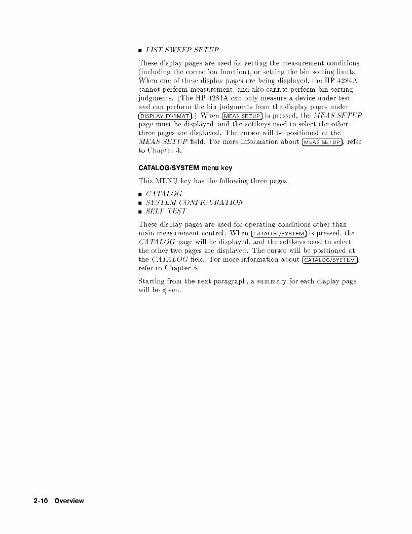
LIST SWEEP SETUP
These display pages are used for setting the measurement conditions(including the correction function), or setting the bin sorting limits.When one of these display pages are being displayed, the HP 4284Acannot perform measurement, and also cannot perform bin sortingjudgments. (The HP 4284A can only measure a device under testand can perform the bin judgments from the display pages under�DISPLAY FORMAT�.) When �MEAS SETUP� is pressed, the MEAS SETUPpage must be displayed, and the softkeys used to select the otherthree pages are displayed. The cursor will be positioned at theMEAS SETUP �eld. For more information about �MEAS SETUP�, referto Chapter 3.
CATALOG/SYSTEM menu key
This MENU key has the following three pages.
CATALOG
SYSTEM CONFIGURATION
SELF TEST
These display pages are used for operating conditions other thanmain measurement control. When �CATALOG/SYSTEM� is pressed, theCATALOG page will be displayed, and the softkeys used to selectthe other two pages are displayed. The cursor will be positioned atthe CATALOG �eld. For more information about �CATALOG/SYSTEM�,refer to Chapter 5.
Starting from the next paragraph, a summary for each display pagewill be given.
2-10 Overview

Summary of Pages Figure 2-5 shows all display pages. Each summary of each page isshown below.
MEAS DISPLAY (under �DISPLAY FORMAT�)
This display page provides the measurement result information, andcontrol settings are entered from this page. The HP 4284A measuresthe device under test from this page, and displays the measurementresults in large characters.
BIN No. DISPLAY (under �DISPLAY FORMAT�)
This display page provides the bin sorting result information, themeasurement results, and comparator function on/o� settings. TheHP 4284A measures the device under test from this page. The binnumber is displayed in large characters, and the measurement resultsare displayed in normal characters.
BIN COUNT DISPLAY (under �DISPLAY FORMAT�)
This display page provides the limit table's conditions, and thecomparator's bin counter results. The HP 4284A can measure thedevice under test from this page, but the measurement results willnot be displayed.
LIST SWEEP DISPLAY (under �DISPLAY FORMAT�)
This display page provides the list sweep measurement results,and the sweep mode step/seq selection. The HP 4284A measuresthe device under test according to the list sweep conditions in theLIST SWEEP SETUP page. An asterisk (*) shows the currentmeasuring point in the list sweep points. The list sweep point cannotbe set from this page. You must use the LIST SWEEP SETUP (in�MEAS SETUP�) page to set the list sweep points.
MEAS SETUP (under �MEAS SETUP�)
This display page provides all of the measurement control settings.The HP 4284A cannot perform a measurement from this page, andthe measurement result can not be displayed on this page. When youmeasure the device under test using the control settings on this page,use one of the display pages from �DISPLAY FORMAT�.
CORRECTION (under �MEAS SETUP�)
This display page provides the correction function. The correctionfunction must be used to measure the device under test accurately.The HP 4284A cannot measure the device under test from thispage, and the measurement results will not be displayed. Whenyou measure a device under test, use one of the display pages from�DISPLAY FORMAT�.
Overview 2-11

LIMIT TABLE SETUP (under �MEAS SETUP�)
This display page provides the limit table settings for bin sorting.The HP 4284A cannot perform a measurement from this page, andthe comparison results can not be displayed. When you want tosee the comparison results, either the BIN No. DISPLAY page(under �DISPLAY FORMAT�) or the BIN COUNT DISPLAY page (under�DISPLAY FORMAT�) must be used.
LIST SWEEP SETUP (under �MEAS SETUP�)
This display page provides the control settings for the List Sweepmeasurement function. The HP 4284A cannot measure the deviceunder test from this page, and the list sweep measurement resultscan not be displayed from this page. When you measure the deviceunder test using the control settings on the LIST SWEEP SETUP
page, the LIST SWEEP DISPLAY page (in �DISPLAY FORMAT�) mustbe used.
CATALOG (under �CATALOG/SYSTEM�)
This display page provides the catalog of the stored contents ininternal memory or a from the memory card.
SYSTEM CONFIG (under �CATALOG/SYSTEM�)
This display page provides the operation of either the HP-IBinterface or the HP 4284A's options, and will also tell you the optioninstallation information.
SELF TEST (under �CATALOG/SYSTEM�)
This display page provides the HP 4284A's self test utilities and thethe Performance Test given in Chapter 10.
2-12 Overview

Figure 2-5. Display Pages (1/3)
Overview 2-13

Figure 2-5. Display Pages (2/3)
2-14 Overview

Figure 2-5. Display Pages (3/3)
Overview 2-15

Basic Operation The HP 4284A's basic operation is described in the followingparagraphs.
Display the desired display page using both the MENU keys andthe softkeys. (Refer to Figure 2-5.)
Move the cursor to the �eld to be used using the CURSOR arrowkeys. The cursor will be an inverse video marker, and the �eld isthe area to which you can set the cursor.
Figure 2-6. CURSOR Keys and Field Operation Example
The softkeys corresponding to the �eld pointed to by the cursorwill be displayed. Select and press a softkey. The numeric entrykeys and �ENTER� are used to enter numeric data.
When one of the numeric entry keys is pressed, the softkeys willchange to the available unit softkeys. You can use these unitsoftkeys instead of �ENTER�. When �ENTER� is used, the numericdata is entered with Hz, V, or A as the default unit depending onthe cursor �eld selected, e.g., test frequency's unit will be Hz, etc.
2-16 Overview

Figure 2-7. Softkey Selection Example
Overview 2-17


3
DISPLAY FORMAT Menu
Introduction This Chapter provides information about the function of each page of�DISPLAY FORMAT�. The following four display pages can be called from�DISPLAY FORMAT�.
MEAS DISPLAY
BIN No. DISPLAY
BIN COUNT DISPLAY
LIST SWEEP DISPLAY
This Chapter describes the functions on each page in the order of thepreceding list.
MEAS DISPLAYPage
When you press �DISPLAY FORMAT�, the MEAS DISPLAY page will bedisplayed. On this MEAS DISPLAY page, the measurement resultsare displayed in large characters, and the following measurementcontrols can be set from this page. (The �eld in parenthesis is usedto set the control function.)
Measurement Function (FUNC )Measurement Range (RANGE)Test Frequency (FREQ)Oscillator Level (LEVEL)DC Bias (BIAS )Integration Time (INTEG)System Menu (SYS MENU )
There are eight �elds on this page: MEAS DISPLAY , FUNC ,RANGE , FREQ , LEVEL, BIAS , INTEG , and SYS MENU . Eachcontrol function is described in the following paragraphs.
This page also provides the following information in monitor areason the displayed page. These conditions can be set from the MEAS
SETUP page or CORRECTION page. (For more detail of thefollowing information, refer to Chapter 4.)
Oscillator Level Voltage/Current Monitor value (Vm, Im)
OPEN, SHORT, LOAD on/o� setting conditions (CORR)
Channel Number (CH ) when the scanner interface is used.
The available �elds and the softkeys which correspond to the �eldson this page are shown in Figure 3-1 and Figure 3-2 respectively.
DISPLAY FORMAT Menu 3-1

Figure 3-1. Available Fields on the MEAS DISPLAY Page
3-2 DISPLAY FORMAT Menu

Figure 3-2. Available Softkeys on the MEAS DISPLAY Page
DISPLAY FORMAT Menu 3-3

Measurement FunctionDescription
The HP 4284A measures two components of the complex impedance(parameters) at the same time in a measurement cycle. Themeasurement parameters are listed as follows.
Primary Parameters
jZj (absolute value of impedance)jYj (absolute value of admittance)L (inductance)C (capacitance)R (resistance)G (conductance)
Secondary Parameters
D (dissipation factor)Q (quality factor)Rs (ESR (equivalent series resistance))Rp (equivalent parallel resistance)X (reactance)B (susceptance)� (phase angle)
The primary parameter measurement result is located on the upperline as two large character lines on this page, and the secondaryparameter measurement result is located on the lower line as twolarge character lines on this page.
The combinations of primary and secondary parameters, includingthe equivalent parallel and serial combinations, are listed in Table3-1.
3-4 DISPLAY FORMAT Menu

Table 3-1. Measurement Function
Primary
Parameter
Serial Mode Parallel Mode
Z Z-� (rad)Z-� (deg)
Y Y-� (rad)Y-� (deg)
C Cs-DCs-QCs-Rs
Cp-DCp-QCp-GCp-Rp
L Ls-DLs-QLs-Rs
Lp-DLp-QLp-GLp-Rp
R R-X
G G-B
Front Panel Operation for Setting the Measurement Function
Perform the following steps to set the measurement function.
1. Use the CURSOR arrow keys to move the cursor to the FUNC�eld. The following softkeys will be displayed.
NNNNNNNNNNNNNNCp-DNNNNNNNNNNNNNNCp-QNNNNNNNNNNNNNNCp-GNNNNNNNNNNNNNNNNNCp-RpNNNNNNNNNNNNNNNNNNNNNNNNNNmore 1/6
2. Select and press a softkey to set the measurement function. If the
softkey you want is not displayed, pressNNNNNNNNNNNNNNNNNNNNNNNNNNmore 1/6 to display the
following set of softkeys.NNNNNNNNNNNNNNCs-DNNNNNNNNNNNNNNCs-QNNNNNNNNNNNNNNNNNCs-RsNNNNNNNNNNNNNNNNNNNNNNNNNNmore 2/6
3. Select and press a softkey to set the measurement function. If the
softkey you want is not displayed, pressNNNNNNNNNNNNNNNNNNNNNNNNNNmore 2/6 to display the
following set of softkeys.NNNNNNNNNNNNNNLp-DNNNNNNNNNNNNNNLp-Q
DISPLAY FORMAT Menu 3-5

NNNNNNNNNNNNNNLp-GNNNNNNNNNNNNNNNNNLp-RpNNNNNNNNNNNNNNNNNNNNNNNNNNmore 3/6
4. Select and press a softkey to set the measurement function. If the
softkey you want is not displayed, pressNNNNNNNNNNNNNNNNNNNNNNNNNNmore 3/6 to display the
following set of softkeys.NNNNNNNNNNNNNNLs-DNNNNNNNNNNNNNNLs-QNNNNNNNNNNNNNNNNNNNNLs-Rs>NNNNNNNNNNNNNNNNNNNNNNNNNNmore 4/6
5. Select and press a softkey to set the measurement function. If the
softkey you want is not displayed, pressNNNNNNNNNNNNNNNNNNNNNNNNNNmore 4/6 to display the
following set of softkeys.NNNNNNNNNNNR-XNNNNNNNNNNNNNNNNNNNNNNNNNNNNNZ-� (deg)NNNNNNNNNNNNNNNNNNNNNNNNNNNNNZ-� (rad)NNNNNNNNNNNNNNNNNNNNNNNNNNmore 5/6
6. Select and press a softkey to set the measurement function. If the
softkey you want is not displayed, pressNNNNNNNNNNNNNNNNNNNNNNNNNNmore 5/6 to display the
following set of softkeys.NNNNNNNNNNNG-BNNNNNNNNNNNNNNNNNNNNNNNNNNNNNY-� (deg)NNNNNNNNNNNNNNNNNNNNNNNNNNNNNY-� (rad)NNNNNNNNNNNNNNNNNNNNNNNNNNmore 6/6
7. Select and press a softkey to set the measurement function.
WhenNNNNNNNNNNNNNNNNNNNNNNNNNNmore 6/6 is pressed, the softkeys shown in step 1 will be
displayed. Retry steps 1 through 7 if you missed the function youwere looking for.
Measurement RangeDescription
The HP 4284A has eight measurement ranges: 10, 100, 300, 1k, 3 k, 10 k, 30 k, and 100 k. When Option 001 is installed,the HP 4284A has nine measurement ranges: 1, 10, 100, 300,1 k, 3 k, 10 k, 30 k, and 100 k. The measurement range isselected according to the DUT's impedance even if measurementparameter is capacitance or inductance.
Figure 3-3 shows the display range and e�ective measuring range foreach measurement range while in the impedance mode (jZj, R, X).For example, 50 k DUT impedance can be measured using from
3-6 DISPLAY FORMAT Menu

the 100 to the 30 k range, but the HP 4284A's measurementaccuracy speci�cation is only met by using the 30 k range. If thisDUT is measured by the 100 k range, UNBAL will be displayed.
Figure 3-3. Effective Measuring Range for Each Measurement Range
Figure 3-4 and Figure 3-5 show the e�ective measuring range of eachmeasurement range, in which the HP 4284A's measurement accuracymeets its speci�cation. When the measurement range is set manually,the optimum measurement range should be selected by matchingthe DUT's impedance to the e�ective measuring range shown inFigure 3-4 and Figure 3-5. When the measurement range is set toAUTO, the optimum measurement range is automatically selectedaccording to the impedance of each DUT.
DISPLAY FORMAT Menu 3-7

Figure 3-4.
Effective Measuring Range
(Oscillator Level � 2V or � 20 mA)
3-8 DISPLAY FORMAT Menu

Figure 3-5.
Effective Measuring Range
(Oscillator Level > 2V or > 20 mA)
Note The measurement range is limited by the test frequency settingwhen the oscillator level is equal to 2 V or less than 2 V. Whenthe measurement range and the test frequency are set under theabove conditions, the test frequency must be set �rst, and then themeasurement range. If you set the measurement range �rst and thenfrequency, the resulting measurement range may not be the one youwanted to set.
Front Panel Operation for Setting the Measurement Range
Perform the following procedure to set the measurement range.
1. Move the cursor to the RANGE �eld using the CURSOR keys.The following softkeys will be displayed.
DISPLAY FORMAT Menu 3-9

NNNNNNNNNNNNNNAUTO This softkey is used to set the measurement range to
AUTO.NNNNNNNNNNNNNNHOLD This softkey is used to change the measurement range
from the AUTO mode to the HOLD mode. Whenthe measurement range is set to the HOLD mode, theimpedance range is �xed at the current range setting,and the impedance range is displayed in the RANGE�eld.
NNNNNNNNNNNNNNNNNNNNINCR * This softkey is used to increment the measurement
range in the HOLD (�xed range) mode.NNNNNNNNNNNNNNNNNNNNDECR + This softkey is used to decrement the measurement
range in the HOLD (�xed range) mode.
2. Use the softkeys to set the measurement range.
Test FrequencyDescription
The HP 4284A operates from 20 Hz to 1 MHz with 8610 frequencysteps in between. All of test frequency points (F) are calculatedvalues using the following formula. (All available frequency pointsabove 1 kHz are shown in Appendix F.)
F =m
n[kHz]
Where,
Frequency [F] m n
20 Hz � F � 5 kHz (8467 points) 60, 62.5,and 75
13 to 3750(integer)
5 kHz < F � 10 kHz (34 points) 120, 125,and 150
13 to 29(integer)
10 kHz < F � 20 kHz (34 points) 240, 250,and 300
13 to 29(integer)
20 kHz < F � 250 kHz (63 points) 480, 500and 600
2 to 29(integer)
250 kHz < F � 500 kHz (6 points) 960, 1000and 1200
2, 3, and 4
500 kHz < F � 1 MHz (6 points) 1920, 2000and 2400
2, 3, and 4
When numeric data is entered, the nearest available frequency pointis automatically set.
3-10 DISPLAY FORMAT Menu

Front Panel Operation for Setting the Test Frequency
There are two ways to set the test frequency. One is to use thesoftkeys, and the other is to use the numeric entry keys. Perform thefollowing steps to set the test frequency.
1. Move the CURSOR to the FREQ �eld. The following softkeyswill be displayed.
NNNNNNNNNNNNNNNNNNNNINCR *
This softkey is the coarse frequency increment softkey used toincrement the test frequency to the next sequentially highertenfold value after 20 Hz. The frequency points set using thissoftkey are as follows.
20 Hz 100 Hz 1 kHz 10 kHz 100 kHz 1 MHz
NNNNNNNNNNNNNNNNNNNNINCR "
This softkey is the �ne frequency increment softkey used toincrement the current test frequency to the next sequentiallyhigher frequency point. There are 10 frequency points betweensuccessive decade values. The sequential frequency points whichcan be set using this softkey are as follows.
20 Hz 100 Hz 1 kHz 10 kHz 100 kHz 1 MHz
25 Hz 120 Hz 1.2 kHz 12 kHz 120 kHz
30 Hz 150 Hz 1.5 kHz 15 kHz 150 kHz40 Hz 200 Hz 2 kHz 20 kHz 200 kHz
50 Hz 250 Hz 2.5 kHz 25 kHz 250 kHz
60 Hz 300 Hz 3 kHz 30 kHz 300 kHz
80 Hz 400 Hz 4 kHz 40 kHz 400 kHz
500 Hz 5 kHz 50 kHz 500 kHz600 Hz 6 kHz 60 kHz 600 kHz
800 Hz 8 kHz 80 kHz 800 kHz
NNNNNNNNNNNNNNNNNNNNDECR #
This softkey is the �ne frequency decrement softkey used todecrease the test frequency to the next sequentially lowerfrequency point. There are ten frequency points betweensuccessive decade values. The frequency points set using this
softkey are the same values as set usingNNNNNNNNNNNNNNNNNNNNINCR " .
NNNNNNNNNNNNNNNNNNNNDECR +
This softkey is the coarse frequency decrement softkey which isused to decrement the test frequency to the next sequentiallylower tenth value. The frequency points set using this softkey
are the same as the frequency points set usingNNNNNNNNNNNNNNNNNNNNINCR * .
2. Select and set the test frequency using either the softkeys or thenumeric entry keys. When the test frequency is entered using thenumeric entry keys, the softkey labels are changed to the available
DISPLAY FORMAT Menu 3-11

units (NNNNNNNNHz ,
NNNNNNNNNNNkHz , and
NNNNNNNNNNNMHz ), and so you can use these softkeys
instead of �ENTER� to enter the units and enter the data. When�ENTER� is used, the numeric data is entered with Hz as the defaultunit.
Oscillator LevelDescription
The HP 4284A's oscillator level can be set as the e�ective value(RMS value) of a sine wave of the test frequency from theHP 4284A's internal oscillator. You can set either the oscillatorvoltage level or the oscillator current level. The output impedance is100.
Note The set value of the oscillator current level is the value set when themeasurement contacts (UNKNOWN Terminals) are shorted together.
The set value of the oscillator voltage level is the value set when themeasurement contacts (UNKNOWN Terminals) are opened.
When the Option 001 (power ampli�er/DC-bias) isn't installed,the oscillator voltage level can be set from 0 Vrms to 2 Vrms with aresolution as listed in Table 3-2, or the oscillator current level can beset from 0 Arms to 20 mArms with a resolution as listed in Table 3-2.
Table 3-2. Oscillator Level and Resolution (Std.)
Mode Oscillator Level Resolution
Voltage 0 Vrms
5 mVrms to 200 mVrms
210 mVrms to 2 Vrms
1 mVrms
10 mVrms
Level 0 Arms
50 �Arms to 2 mArms
2.1 mArms to 20 mArms
10 �Arms
100 �Arms
When the option 001 (power ampli�er/DC-bias) is installed, theoscillator voltage level can be set form 0 Vrms to 20 Vrms with aresolution as listed in Table 3-3, or the oscillator current level can beset from 0 Arms to 200 mArms with a resolution as listed in Table 3-3.
Note It is possible to make the option 001 valid or invalid from the MEAS
SETUP page. When the option 001 function is used, the high powermode must be set to ON in the MEAS SETUP page. (For moreinformation, refer to Chapter 4.)
3-12 DISPLAY FORMAT Menu

Table 3-3. Oscillator Level and Resolution (Opt.001)
Mode Oscillator Level Resolution
Voltage 0 Vrms
5 mVrms to 200 mVrms
210 mVrms to 2 Vrms
2.1 Vrms to 20 V rms
1 mVrms
10 mVrms
100 mVrms
Level 0 Arms
50 �Arms to 2 mArms
2.1 mArms to 20 mArms
21 mArms to 200 mArms
10 �Arms
100 �Arms
1 mArms
The HP 4284A can measure a device using a constant voltage orcurrent level by using the automatic level control function. (Theautomatic level control function (ALC �eld) can be set to ON fromthe MEAS SETUP page.) When a constant voltage or current levelmeasurement is performed, the asterisk mark (*) is located at thehead of the oscillator level value. For more information about theautomatic level control function, refer to Chapter 4.
Front Panel Operation for Setting the Oscillator Level
There are two ways to set the oscillator level. One is to use thesoftkeys, and the other is to use the use the numeric entry keys.Perform the following steps to set the oscillator level.
1. Move the cursor to the LEVEL �eld. The following softkeys willbe displayed.
NNNNNNNNNNNNNNNNNNNNINCR *
Press this softkey to increases the oscillator's output level.NNNNNNNNNNNNNNNNNNNNDECR +
Press this softkey to decreases the oscillator's output level.
2. Select and set the oscillator level using either the softkeys or thenumeric entry keys. When the oscillator level is entered using thenumeric entry keys, the softkey labels are changed to the available
units labels (NNNNNNNNmV ,
NNNNNV ,
NNNNNNNN�A ,
NNNNNNNNmA , and
NNNNNA ), and you can use these
softkeys to enter the units and enter the data instead of �ENTER�.When �ENTER� is used, the numeric data is entered with V or A asthe default unit.
Note When you want to change the oscillator level from voltage to current,or from current to voltage, the numeric entry keys and units' softkeysmust be used.
DISPLAY FORMAT Menu 3-13

DC BiasDescription
The HP 4284A has internal dc bias voltage selections of 0 V, 1.5 V,and 2.0 V.
When option 001 is installed, the dc bias voltage can be set from 0V to � 40 V with a resolution as listed in Table 3-4, or the DC biascurrent can be set from 0 A to � 100 mA with a resolution as listedin Table 3-4.
Note Option 001 can be made valid or invalid from the MEAS SETUP
page. When the option 001 function is used, the high power modemust be set to ON from the MEAS SETUP page. (For moreinformation, refer to Chapter 4.)
Table 3-4. DC bias and Resolution (Opt.001)
Mode DC Bias Level Resolution
Voltage � (0 V to 4 V)
� (4.002 V to 8 V)
� (8.005 V to 20 V)
� (20.01 V to 40 V)
1 mV2 mV5 mV10 mV
Current � (0 A to 40 mA)
� (40.02 mA to 80 mA)� (80.05 mA to 100 mA)
10 �A
20 �A50 �A
Note The setting value of the dc bias current is the value set when themeasurement contacts (UNKNOWN Terminals) are shorted. (Referto Figure 3-6.) When a DUT is connected to the measurementcontacts, the setting current value is di�erent from the actual currentthrough the DUT. To determine the bias current through a device,refer to BIAS CURRENT ISOLATION FUNCTION, Chapter 4.
The setting value of the DC bias voltage is the value set when themeasurement contacts (UNKNOWN Terminals) are opened.
3-14 DISPLAY FORMAT Menu

Figure 3-6. DC BIAS Current
Note The DC bias will be output after setting �DC BIAS� on the front panelto ON. �DC BIAS� is used to enable the dc bias output. �DC BIAS� is atoggle type switch, and the DC BIAS on/o� LED indicator is locatedabove �DC BIAS�. When �DC BIAS� is set to ON, the DC BIAS on/o�LED indicator is ON. When �DC BIAS� is set to OFF, the DC BIASon/o� LED indicator is OFF. If �DC BIAS� is set to OFF, even thoughthe dc bias is set to ON according to the LCD display, the set dc biasisn't output.
Note When both the dc bias and the oscillator level are set under thefollowing conditions, the amount of the dc bias plus the oscillatorlevel is limited as listed in Table 3-5.
Option 001 is installed.
The high power mode (Hi-PW) is set to ON.
�DC BIAS� on the front panel is set to ON.
Table 3-5. DC Bias and Oscillator level Setting limits
DC Bias
Setting
Osc Level
Setting
Limit
Vdc(V) Vosc(Vrms) Vosc �p2 � 1.1 + Vdc � 1.002 < 42 V
Vdc(V) Iosc(Arms) Iosc �p2 � 110 + Vdc � 1.002 < 42 V
Idc(A) Vosc(Vrms) Vosc �p2 � 1.1 + Idc � 100.2 < 42 V
Idc(A) Iosc(Arms) Iosc � (p2 / �) � 1.1 + Idc � 1.01 < 0.11 A
When Option 001 is installed, the DC bias voltage across the DUTcan be monitored at the INT DC BIAS MONITOR connector on therear panel. See Figure 3-7. There are resistors (approximately 9.9
DISPLAY FORMAT Menu 3-15

k) in series between the INT DC BIAS MONITOR connector andthe HCUR Terminal. So if you use a dc voltmeter to �nd the actualDC bias voltage, use the following formula to calculate it.
Vdc = (1 +9:9k
Rin
)� Vm � Vlow
Where,
Vdc : Actual DC bias voltage
Rin : Input Resistor of the DC voltage meter
Vm : Actual monitor value at the INT DC BIASMONITOR connector
Vlow : Residual voltage at the LOW Terminal (Typical: 2mV, Max.: 6 mV (DCI:ISO ON), 20 mV (DCI:ISOOFF))
Figure 3-7. DC BIAS Monitor Circuits
Front Panel Operation for Setting the DC Bias
There are two ways to set the DC bias, one is to use the softkeys,and the other is to use the numeric entry keys. Perform the followingsteps to set the DC bias.
1. Move the cursor to the BIAS �eld. The following softkeys will bedisplayed.
a.NNNNNNNNNNNNNNNNNNNNINCR *
Press this softkey to increase the DC bias level.
b.NNNNNNNNNNNNNNNNNNNNDECR +
Press this softkey to decrease the DC bias level.
3-16 DISPLAY FORMAT Menu

2. Set the dc bias to your desired bias using either the softkeys orthe numeric entry keys. When the dc bias is entered using thenumeric entry keys, the softkey labels are changed to the available
units (NNNNNNNNmV ,
NNNNNV ,
NNNNNNNN�A ,
NNNNNNNNmA , and
NNNNNA ), and so you can use these softkeys
instead of �ENTER�. When �ENTER� is used, the numeric data isentered with V or A as the default unit.
Note When you want to change the DC bias from voltage to current orfrom current to voltage, you must use the numeric entry keys and theunits' softkeys.
3. Set �DC BIAS� on the front panel to ON to output the dc bias.
Integration TimeDescription
The HP 4284A's measurement time is determined by the following.
Integration Time (A/D conversion)Averaging Rate (number of measurement averaged)Delay Time (time delay between the trigger and the start of themeasurement)Measurement result's display time
On this page, only the Integration Time in the above items can beset, the other settings except for the measurement result's displaytime can be set from the MEAS SETUP page.
The HP 4284A uses an integrating A/D converter in the internalcircuits to convert the analog signal to a digital signal. TheIntegration Time is the time required to perform an A/D conversion.Generally, a longer conversion time will result in more stable andaccurate measurement results. SHORT, MEDIUM, or LONGintegration times can be selected. The measurement time of eachintegration time is shown in \Measurement Time" in Chapter 9.
Front Panel Operation for Setting the Integration Time
Perform the following steps to set the integration time.
1. Move the cursor to the INTEG �eld. The following softkeys willbe displayed.
NNNNNNNNNNNNNNNNNSHORTNNNNNNNNNNNMEDNNNNNNNNNNNNNNLONG
2. Use the preceding softkeys to select and set the integration time.
DISPLAY FORMAT Menu 3-17

System Menu The system menu allows you to perform the following functions.
Load/StoreDecimal �xed pointPrinterKeylock
This paragraph describes each function in the order listed above.
Load/Store Function
The HP 4284A uses two types of non-volatile memory: the internalEEPROM and an external memory card for storing and retrieving amaximum of 20 sets of instrument control settings. The followingdata will be stored in non-volatile memory as one record.
Control settings on the MEAS SETUP page.
Measurement FunctionTest FrequencyMeasurement RangeOscillator LevelDC BiasIntegration TimeAveraging RateDelay TimeTrigger ModeALC on/o�Hi-PW mode on/o�V Monitor on/o�I Monitor on/o�Deviation Measurement A/B (�ABS/�%/o�)Deviation Measurement A/B Reference ValueBias Current Isolation on/o�
Control settings on the LIMIT TABLE page.
Measurement Function (Swap Parameter)Nominal ValueLimit Mode for the Primary ParameterAuxiliary Bin on/o�Comparator Function on/o�Low/High Limits for Each Bin
Control setting on the BIN COUNT DISPLAY page.
Bin Count Capability on/o�
Control settings on the LIST SWEEP SETUP page.
Sweep ModeAll Sweep PointsAll Low/High Limits including the limit mode (A or B)
Comment Line
Display page format
3-18 DISPLAY FORMAT Menu

Note �DC BIAS� ON/OFF condition on the front panel cannot be stored innon-volatile memory.
When the memory card is inserted into the MEMORY card slot andthe HP 4284A is turned on, the HP 4284A's Auto Load function willload the control settings stored in record number 10. If there are nocontrol settings stored in record number 10, the power-on defaultsettings will be used, the same ones loaded without the memory card.
Note The following items are stored in internal nonvolatile memorywithout using the load/store function.
Control settings on the CORRECTION page.
OPEN, SHORT, LOAD correction on/o�OPEN, SHORT correction data for all test frequencies.OPEN, SHORT, LOAD correction data at FREQ 1, FREQ 2,FREQ 3. (OPEN correction data at each frequency, SHORTcorrection data at each frequency, and LOAD correctionreference data and actual data at each frequency.)
Control settings on the SYSTEM CONFIG page.
Beeper on/o�HP-IB addressTalk Only on/o�Handler I/F on/o�Scanner I/F on/o�
Perform the following steps to store the control settings to theinternal non-volatile memory or to the external memory card.
1. Select and set all control settings on the MEAS DISPLAY page.
2. Move the cursor to the SYS MENU �eld.
3. Insert a memory card in the MEMORY card slot, if you are goingto store the data to the memory card.
4. PressNNNNNNNNNNNNNNNNNSTORE . The message Enter record number to STORE will
be displayed on the system message line.
5. Enter a record number using the numeric entry keys and �ENTER�to store the current control settings. Then when the record isstored in the internal EEPROM, the record number can be setfrom 0 to 9. When the record is stored in the memory card, recordnumbers from 10 to 19 can be set used.
Perform the following steps to load the control settings from theinternal non-volatile memory or from an external memory card.
1. Move the cursor to the SYS MENU �eld.
2. Insert the memory card into the MEMORY card slot, if you aregoing to use a memory card.
DISPLAY FORMAT Menu 3-19

3. PressNNNNNNNNNNNNNNLOAD . The message Enter record number to LOAD will be
displayed on the system message line.
4. Enter record number you want to load using the numeric entrykeys and �ENTER�.
Fixed Decimal Point Function
The HP 4284A displays the measurement data using a six digit oating point display format. The �xed decimal point function isused to display the measurement data using a �xed point displayformat. This function can also be used to change the number ofdigits displayed.
Perform the following steps to use the �xed decimal point function.
1. Move the cursor to the SYS MENU �eld.
2. PressNNNNNNNNNNNNNNNNNNNNNNNNNNNNNNNND.P. FIX A to �x the decimal point for the main
parameter's data. The � mark will be displayed at the decimal
�xed point. Each timeNNNNNNNNNNNNNNNNNNNNNNNNNNNNNNNND.P. FIX A is pressed, the last digit is
dropped, the value is rounded o�.
3. PressNNNNNNNNNNNNNNNNNNNNNNNNNNNNNNNND.P. FIX B to �x the decimal point for the sub
parameter's data. The � mark will be displayed at the decimal
�xed point. Each timeNNNNNNNNNNNNNNNNNNNNNNNNNNNNND.P.FIX B is pressed, the value is rounded
o� giving one less digit.
Note In the following cases the �xed decimal point function isautomatically disabled.
The measurement function is changed.
When the deviation measurement (which is set on the MEAS
SETUP page) is performed, the deviation measurement function(�ABS, �%, OFF) is changed.
Printer Function
The HP 4284A's printer function is used to make a hardcopy ofthe displayed information (except for the softkey labels) or themeasurement results without the need of an external controller. TheHP 4284A must be set to the HP-IB talker mode, and the printermust be set to the HP-IB listener mode. There are two print modes:the PRINT DISPLAY mode and the PRINT DATA mode.
PRINT DISPLAY mode
The print display mode is used to print out all of information onthe displayed page by sending ASCII character strings to a printer.An example is shown Figure 3-8.
3-20 DISPLAY FORMAT Menu

<MEAS DISPLAY> SYS MENU
FUNC : Cp-D RANGE: AUTO
FREQ :1.00000MHz BIAS : 1.000 V
LEVEL: 1.00 V INTEG: MED
C p : 9 9 . 9 9 2 9 p F
D : . 0 0 0 0 7 1
Vm : 1.009 V Im : 633.9uA
CORR: OPEN,SHORT,LOAD CH: 0
Figure 3-8. MEAS DISPLAY Page Example
Note The following characters are not recognized by the printer, so thecharacter in [ ] on the same line will be printed instead.
�! t (space)
� �! [0]
� �! [d]
� �! [u]� �! [>]
PRINT DATA mode
The print data mode is used to print out the measurement resultsusing the following format. This format is the same as the ASCIIformat used for data transfer via HP-IB. For details, refer toChapter 7.
<DATA A>,<DATA B>,<STATUS>,<BIN No.><CR><LF>
<DATA A> ::= The measurement results of the main parameter(jZj, jYj, C, L, R, G).12 ASCII characters (SN.NNNNNESNN)
<DATA B> ::= The measurement results of the sub parameter(�, D, Q, G, Rs, X, B). 12 ASCII characters(SN.NNNNNESNN)
<STATUS> ::= 0: Normal Measurement.1: Analog Bridge is unbalanced.2: A/D converter not working.3: Signal source is overloaded.4: ALC unable to regulate.
<BIN No.> ::= 0: OUT OF BINS1: BIN 12: BIN 2
DISPLAY FORMAT Menu 3-21

3: BIN 3...8: BIN 89: BIN 910: AUX BIN
Note BIN number data is valid only when the comparator function isset to ON. When the comparator function is set to OFF, the BINnumber data isn't output as shown below.
<DATA A>,<DATA B>,<STATUS><CR><LF>
In the talk only mode, the HP 4284A waits for the completion of thehandshake before starting the next measurement. The measurementcycle of the HP 4284A depends on the printer's speed.
When the <STATUS> is 1 or 2 the measurement data is 9.9E37.When the <STATUS> is 0, 3, or 4 the actual measurement data areoutput.
Use the PRINT DISP mode and perform the following steps to printout all of information on the display page except for the softkeylabels.
1. Connect the HP 4284A to the printer using an HP-IB cable.
2. Set the printer to the listen only mode.
3. Set the talk only mode to ON from the SYSTEM CONFIG page.
4. Press DISPLAY FORMAT to display the MEAS DISPLAY page.
5. Move the cursor to the SYS MENU �eld.
6. PressNNNNNNNNNNNNNNNNNNNNNNNNNNmore 1/2 .
7. PressNNNNNNNNNNNNNNNNNNNNNNNNNNNNNNNNPRINT DISP .
Use the PRINT DATA mode and perform the following steps to printout the measurement results to the printer.
Connect the HP 4284A to the printer using an HP-IB cable.
Set the printer to the listen only mode.
Set the talk only mode to ON from the SYSTEM CONFIG page.
Press �DISPLAY FORMAT� to display the MEAS DISPLAY page.
Move the cursor to the SYS MENU .
PressNNNNNNNNNNNNNNNNNNNNNNNNNNmore 1/2 .
PressNNNNNNNNNNNNNNNNNNNNNNNNNNNNNNNNPRINT DATA . The marker will appear at the side of
NNNNNNNNNNNNNNNNNNNNNNNNNNNNNNNNPRINT DATA . The measurement results are sent out to the printer
on subsequent measurements.
3-22 DISPLAY FORMAT Menu

Keylock Function
The HP 4284A has keyboard lock-out capability that disablesall front panel operation except for the power LINE switch,
CONTRAST knob, �TRIGGER� key, andNNNNNNNNNNNNNNNNNNNNNNNKEYLOCK . This is useful when
you don't want the control settings changed, for example, if theHP 4284A is performing bin sorting for a large number of capacitors.
Perform the following steps to disable all front panel operation on theMEAS DISPLAY page.
1. Move the cursor to the SYS MENU �eld.
2. PressNNNNNNNNNNNNNNNNNNNNNNNNNNmore 1/2 .
3. PressNNNNNNNNNNNNNNNNNNNNNNNNNNKEY LOCK (which is a toggle type softkey). The key mark
will be shown on the left side ofNNNNNNNNNNNNNNNNNNNNNNNNNNKEY LOCK , and the Keys locked
message will be displayed on the system message line.
4. PressNNNNNNNNNNNNNNNNNNNNNNNNNNKEY LOCK again, when you want to enable all front panel
keys again.
BIN No. DISPLAYPage
When you press �DISPLAY FORMAT� , andNNNNNNNNNNNNNNNNNNNNNNNBIN No. , the BIN No.
DISPLAY page will be displayed. The bin sorting results aredisplayed in large characters and the measurement results aredisplayed in normal characters on the BIN No. DISPLAY page, andthe following measurement controls can be set from the BIN No.
DISPLAY page. (The �eld in parenthesis is used when this control isset.)
Comparator Function ON/OFF (COMP )System Menu (SYS MENU )
There are three �elds on this page: <BIN No. DISPLAY>, COMP ,and SYS MENU �elds.
Each control is described in the following paragraphs.
This page also provides the following information in the monitorareas (each monitor area looks like a �eld, but is not). Theseconditions can be set from the MEAS SETUP page, and mostconditions can be set from the MEAS DISPLAY page.
Measurement Function (FUNC )Measurement Range (RANGE)Test Frequency (FREQ)Oscillator Level (LEVEL)DC Bias (BIAS )Integration Time (INTEG)OPEN, SHORT, LOAD on/o� setting conditions (CORR)
The available �elds and the softkeys which correspond to each �eldon this page are shown in Figure 3-9 and Figure 3-10.
DISPLAY FORMAT Menu 3-23

Figure 3-9. Available Fields on the BIN No. DISPLAY Page
Figure 3-10. Available Softkeys on the BIN No. DISPLAY Page
3-24 DISPLAY FORMAT Menu

Comparator FunctionON/OFF Description
The HP 4284A's built-in comparator can sort devices into amaximum of ten bins (BIN 1 to BIN 9 and the OUT OF BINS bin)using a maximum of nine pairs of primary limits and one pair ofsecondary parameter limits. Also, a device whose primary parameteris within limits, but whose secondary parameter measurement resultis not within limits can be sorted into an AUXiliary BIN. Thecomparator function is especially useful when using the HP 4284Awith a component handler (handler interface option is installed).These limit settings for bin sorting are only set on the LIMIT
TABLE page under �MEAS SETUP� (refer to the Chapter 4). So thisCOMP �eld allows you to only set the comparator function to ON orOFF.
Front Panel Operation for Setting the Comparator Function to ON or
OFF
Perform the following steps to set the comparator function to ON orOFF.
1. Move the cursor to the COMP �eld. The following softkeys willbe displayed.
NNNNNNNNON
NNNNNNNNNNNOFF
2. Use the softkeys to set the comparator function to ON or OFF.
System Menu The system menu on this page allows you to use the followingfunctions.
Load/StorePrinterKeylock
These functions are the same as the functions on the system menuon the MEAS DISPLAY page (Refer to page 3-19,\System Menu").So only the procedure for each function is given in the followingparagraphs.
Load/Store Function
Perform the following steps to store the control settings to theinternal non-volatile memory or the external memory card or loadthe control settings from the internal non-volatile memory or theexternal memory card.
1. Set all controls.
2. ON the BIN No. DISPLAY page move the cursor to the SYSMENU �eld using the CURSOR keys.
DISPLAY FORMAT Menu 3-25

3. If you are going to store the settings on a memory card, insert amemory card to the MEMORY card slot.
4. PressNNNNNNNNNNNNNNNNNSTORE when you want to use the STORE function. The
message Enter record number to STORE will be displayed on thesystem message line.
PressNNNNNNNNNNNNNNLOAD when you want to use the LOAD function. Then the
Enter record number to LOAD will be displayed on the systemmessage line.
5. Use the numeric entry keys and �ENTER� to enter the recordnumber at which the current control settings will be STORED toor LOADED from.
Printer Function
Perform the following steps to print out the displayed page or themeasurement data using the PRINT DISP mode or PRINT DATAmode.
1. Connect the HP 4284A to the printer using an HP-IB cable
2. Set the printer to the listen only mode.
3. Set the talk only mode to ON on the SYSTEM CONFIG page.
4. Press �DISPLAY FORMAT�, and pressNNNNNNNNNNNNNNNNNNNNNNNBIN No. to display the BIN
No. DISPLAY page.
5. Move the cursor to the SYS MENU �eld.
6. PressNNNNNNNNNNNNNNNNNNNNNNNNNNmore 1/2 .
7. PressNNNNNNNNNNNNNNNNNNNNNNNNNNNNNNNNPRINT DISP when you want to print out the displayed page.
The displayed page is printed out as shown in Figure 3-8.
PressNNNNNNNNNNNNNNNNNNNNNNNNNNNNNNNNPRINT DATA when you want to print out the measurement
data. The marker will appear besideNNNNNNNNNNNNNNNNNNNNNNNNNNNNNNNNPRINT DATA . The
measurement results are printed out on subsequent measurements.
3-26 DISPLAY FORMAT Menu

<BIN No. DISPLAY> SYS MENU
FUNC : Cp-D RANGE: AUTO
FREQ :1.00000MHz BIAS : 1.000 V
LEVEL: 1.00 V INTEG: MED
COMP : ON
B I N 6
Cp: 99.9609pF D : .000387
CORR: OPEN,SHORT,LOAD CH: 0
Figure 3-11. BIN No. DISPLAY Page Example
Keylock Function
Perform the following steps from the BIN No. DISPLAY page todisable all front panel operation.
1. Move the cursor to the SYS MENU �eld.
2. PressNNNNNNNNNNNNNNNNNNNNNNNNNNmore 1/2 .
3. PressNNNNNNNNNNNNNNNNNNNNNNNNNNKEY LOCK (which is a toggle type softkey). The key mark
will be shown on the left side ofNNNNNNNNNNNNNNNNNNNNNNNNNNKEY LOCK , and the Keys locked
message will be displayed on the system message line.
4. PressNNNNNNNNNNNNNNNNNNNNNNNNNNKEY LOCK again to enable all front panel keys.
DISPLAY FORMAT Menu 3-27

BIN COUNTDISPLAY Page
When you press �DISPLAY FORMAT� andNNNNNNNNNNNNNNNNNNNNNNNNNNNNNBIN COUNT , the BIN COUNT
DISPLAY page will be displayed. On the BIN COUNT DISPLAY
page, the comparator's count results are displayed, and the followingmeasurement controls can be set.
System Menu (SYS MENU )
So there are two �elds on this page: <BIN COUNT DISPLAY> andSYS MENU �elds.
The system menu is described in the following paragraphs.
This page also provides the following information in monitorareas (the monitor areas look like �elds, but they are not). Theseconditions can be set from the LIMIT TABLE page. (For moredetails on the following controls, refer to Chapter 4.)
Nominal Value
Measurement Function
Bin Sorting Low/High Limits
The available �elds and the softkeys which corresponded to each �eldon this page are shown in Figure 3-12 and Figure 3-13.
3-28 DISPLAY FORMAT Menu

Figure 3-12. Available Fields on the BIN COUNT DISPLAY Page
Figure 3-13. Available Softkeys on the BIN COUNT DISPLAY Page
DISPLAY FORMAT Menu 3-29

System Menu The system menu on this page allows you to perform the followingfunctions.
Counter ON/OFFLoad/StorePrinterKeylock
These functions, except for the counter function, are the same asthe functions displayed on the system menu of the MEAS DISPLAY
page. (Refer to page 3-19, \System Menu") So in the case ofthe counter function, the description and setting procedures aredescribed in the following paragraphs, for the other functions, onlythe procedure is described.
Counter Function
The HP 4284A has bin counting capability. When many devices arebeing sorted into bins using the comparator function, the numberof devices sorted into each bin is counted. The maximum count is999999, the over ow message \----" will be displayed when thisvalue is exceeded. The bin counter will still be operating, so you canonly get the count data via HP-IB.
Perform the following steps to set the counter function to ON orOFF from the BIN COUNT DISPLAY page.
Move the cursor to SYS MENU �eld on the BIN COUNT
DISPLAY page.
PressNNNNNNNNNNNNNNNNNNNNNNNNNNCOUNT ON to set the counter function to ON. An arrow will
be displayed at the left of COUNT.
PressNNNNNNNNNNNNNNNNNNNNNNNNNNNNNCOUNT OFF when you want to set the counter function to
OFF. The arrow will disappear.
PressNNNNNNNNNNNNNNNNNNNNNNNNNNNNNNNNNNNRESET COUNT when all counts are reset to zero. The message
RESET COUNT, do you proceed? will be displayed on the system
message line, andNNNNNNNNNNNYES and
NNNNNNNNNO will be displayed. Press
NNNNNNNNNNNYES .
Load/Store Function
Perform the following steps to store the current control settings tothe internal non-volatile memory or the external memory card, andto load the control settings from the internal non-volatile memory orthe external memory card.
1. Set all controls.
2. Move the cursor to the SYS MENU �eld on the BIN COUNT
DISPLAY page.
3. Insert a memory card into the MEMORY card slot, if you aregoing to store or load the settings to or from a memory card.
4. PressNNNNNNNNNNNNNNNNNNNNNNNNNNmore 1/3 .
3-30 DISPLAY FORMAT Menu

5. PressNNNNNNNNNNNNNNNNNSTORE when you want to use the STORE function. The
message Enter record number to STORE will be displayed on thesystem message line.
PressNNNNNNNNNNNNNNLOAD when you want to use the LOAD function. Then the
Enter record number to LOAD will be displayed on the systemmessage line.
6. Use the numeric entry keys and �ENTER� to enter the recordnumber at which the current control settings will be STORED toor LOADED from.
Printer Function
Use the PRINT DISP or PRINT DATA mode and perform thefollowing steps to print out the display page or the measurementdata.
1. Connect the HP 4284A to the printer using an HP-IB cable.
2. Set the printer to the listen only mode.
3. Set the talk only mode to ON on the SYSTEM CONFIG page.
4. Press �DISPLAY FORMAT�, and pressNNNNNNNNNNNNNNNNNNNNNNNNNNNNNBIN COUNT to display the BIN
COUNT DISPLAY page.
5. Move the cursor to the SYS MENU �eld.
6. PressNNNNNNNNNNNNNNNNNNNNNNNNNNmore 1/3 and then press
NNNNNNNNNNNNNNNNNNNNNNNNNNmore 2/3 .
7. PressNNNNNNNNNNNNNNNNNNNNNNNNNNNNNNNNPRINT DISP when you want to print out the displayed page.
Figure 3-10 shows a sample print out of the display page.
PressNNNNNNNNNNNNNNNNNNNNNNNNNNNNNNNNPRINT DATA when you want to print out the measurement
results. The marker will appear besideNNNNNNNNNNNNNNNNNNNNNNNNNNNNNNNNPRINT DATA . The
measurement results are printed out on subsequent measurements.
<BIN COUNT DISPLAY> SYS MENU
FUNC : Cp-D NOM : 100.000pF
BIN LOW [ % ] HIGH[ % ] >COUNT
1 - 0.001 + 0.001 0
2 - 0.003 + 0.003 0
3 - 0.005 + 0.005 0
4 - 0.010 + 0.010 0
5 - 0.030 + 0.030 0
6 - 0.050 + 0.050 76
7 - 0.100 + 0.100 0
8 - 0.500 + 0.500 0
9 - 1.000 + 1.000 1
2nd +.000000 +.000300 [ ]
REJ CNT AUX: 12 OUT: 38
Figure 3-14. BIN COUNT DISPLAY Page Example
DISPLAY FORMAT Menu 3-31

Keylock Function
Perform the following steps to disable all front panel operations onthe BIN COUNT DISPLAY page.
Move the cursor to the SYS MENU �eld.
PressNNNNNNNNNNNNNNNNNNNNNNNNNNmore 1/3 , and press
NNNNNNNNNNNNNNNNNNNNNNNNNNmore 2/3 .
PressNNNNNNNNNNNNNNNNNNNNNNNNNNKEY LOCK (a toggle type softkey). The key mark will be
displayed on the left side ofNNNNNNNNNNNNNNNNNNNNNNNNNNKEY LOCK , and the message Keys
locked will be displayed on the system message line.
PressNNNNNNNNNNNNNNNNNNNNNNNNNNKEY LOCK again, if you want to enable the front panel keys.
LIST SWEEPDISPLAY Page
The HP 4284A's LIST SWEEP function permits entry of up to tenfrequencies, signal levels, or DC bias levels, and the measurementlimits on the LIST SWEEP SETUP page under the MEAS
SETUP page. These points are automatically swept and themeasurement results are compared to the limits set. When you press
�DISPLAY FORMAT� andNNNNNNNNNNNNNNNNNNNNNNNNNNNNNNNNLIST SWEEP , the LIST SWEEP DISPLAY
page will be displayed. On the LIST SWEEP DISPLAY page, thesweep points are swept and the measurement results are comparedto the limits. During a sweep, an asterisk mark (*) will appears onthe left side of the current measuring list sweep point. The followingmeasurement controls can be set from this page. (Each �eld inparenthesis is used when that control is set.)
Sweep Mode of the List sweep Measurement (MODE)System Menu (SYS MENU )
So there are three �elds on this page: <LIST SWEEP DISPLAY>,MODE , and SYS MENU �elds.
The system menu is described in the following paragraphs.
The list sweep point can not be set from this page, but can only beset from the LIST SWEEP SETUP page.
The available �elds and the softkeys which corresponded to each �eldon this page are shown in Figure 3-15 and Figure 3-16.
3-32 DISPLAY FORMAT Menu
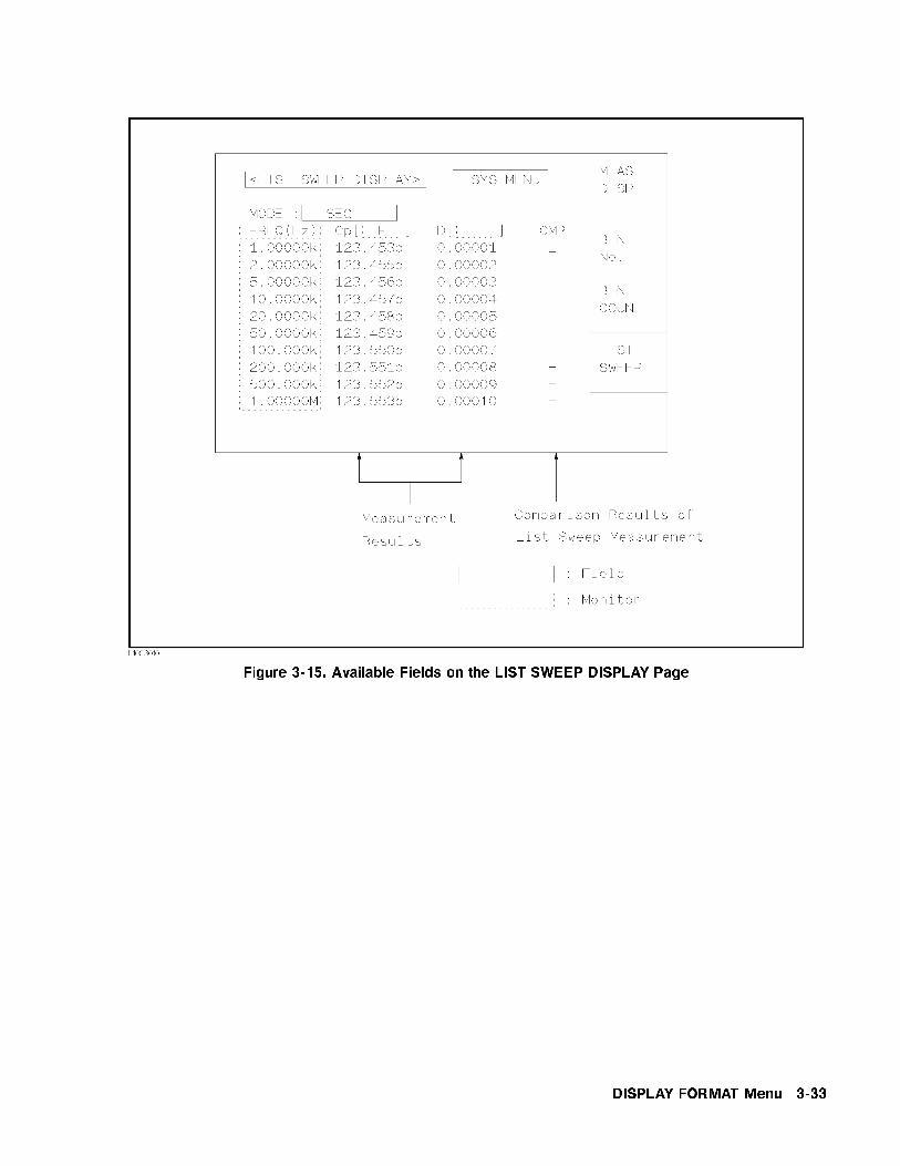
Figure 3-15. Available Fields on the LIST SWEEP DISPLAY Page
DISPLAY FORMAT Menu 3-33

Figure 3-16. Available Softkeys on the LIST SWEEP DISPLAY Page
Sweep Mode The HP 4284A's List Sweep Measurement function permits upto 10 test frequencies, oscillator levels, or DC bias points to beautomatically measured. There are two measurement modes forlist sweep measurements: sequential (SEQ) mode and step (STEP)mode. In the case of SEQ mode, when the HP 4284A is triggeredonce, all sweep points are automatically swept. In the case of theSTEP mode, each time the HP 4284A is triggered the sweep point isswept by one step.
Figure 3-17. SEQ Mode and STEP Mode
Note When two or more sweep points are the same, and are adjacent theHP 4284A measures the device once, and then the measurementresult is compared to limits set for each sweep point.
3-34 DISPLAY FORMAT Menu

Front Panel Operation for Setting the Sweep Mode of the List Sweep
Measurement
Perform the following steps to set the list sweep measurement modeto the SEQ or STEP modes.
1. Move the cursor to the MODE �eld. The following softkeys willbe displayed.
NNNNNNNNNNNSEQNNNNNNNNNNNNNNSTEP
2. Use the softkeys to select and set the list sweep measurementmode (SEQ or STEP mode).
System Menu The system menu on this page allows you to perform the followingfunctions.
Load/StorePrinterKeylock
These functions are the same as the functions of the system menu onthe MEAS DISPLAY page. (Refer to \System Menu" on page 3-19)So only the procedure is given for each function.
Load/Store Function
Perform the following steps to store the control settings in theinternal non-volatile memory or in an external memory card.
1. Set all controls.
2. Move the cursor to the SYS MENU �eld.
3. Insert a memory card to the MEMORY card slot, if you are goingto store the settings in a memory card.
4. PressNNNNNNNNNNNNNNNNNSTORE . The message Enter record number to STORE will
be displayed on the system message line.
5. Use the entry keys and �ENTER� to enter the record number wherethe current control setting are to be stored. When the data is tobe stored in the internal EEPROM, record numbers 0 to 9 areused, and when the record is stored in a memory card, recordnumbers 10 to 19 are used.
Perform the following steps to load the control settings from theinternal non-volatile memory or from an external memory card.
1. Move the cursor to the SYS MENU �eld.
2. Insert the appropriate memory card into the MEMORY card slot,if you are going to load the settings from a memory card.
3. PressNNNNNNNNNNNNNNLOAD . The message Enter record number to LOAD will be
displayed on the system message line.
DISPLAY FORMAT Menu 3-35

4. Enter the record number using the numeric entry keys and�ENTER�.
Printer Function
Perform the following steps to print out the display page or to listsweep measurement results using the PRINT DISP mode or PRINTDATA mode.
1. Connect the HP 4284A to the printer using an HP-IB cable.
2. Set the printer to the listen only mode.
3. Set the talk only mode to ON from the SYSTEM CONFIG page.
4. Press �DISPLAY FORMAT�, and pressNNNNNNNNNNNNNNNNNNNNNNNNNNNNNNNNLIST SWEEP to display the
LIST SWEEP DISPLAY page.
5. Move the cursor to the SYS MENU �eld.
6. PressNNNNNNNNNNNNNNNNNNNNNNNNNNmore 1/2 .
7. PressNNNNNNNNNNNNNNNNNNNNNNNNNNNNNNNNPRINT DISP to print out the display page. The displayed
page will be printed out as shown in Figure 3-18.
<LIST SWEEP DISPLAY> SYS MENU
MODE : SEQ
FREQ[Hz] Cp[ F ] D[ ] CMP
1.00000k 99.6257p .008338 L
2.00000k 99.8398p .003280 L
3.00000k 99.8841p .002077 L
4.00000k 99.9033p .001570
5.00000k 99.9187p .001228
6.00000k 100.021p .000936
6.94444k 100.016p .000787
8.00000k 100.002p .000691
8.92857k 100.015p .000646
10.0000k 100.014p .000810
Figure 3-18. LIST SWEEP DISPLAY Page Example
PressNNNNNNNNNNNNNNNNNNNNNNNNNNNNNNNNPRINT DATA to print out the measurement results. A marker
will appear besideNNNNNNNNNNNNNNNNNNNNNNNNNNNNNNNNPRINT DATA . The measurement results will be
printed out on subsequent measurements according to the followingdata format. (This format is as same as the ASCII format of thedata transfer via HP-IB. For more details, refer to Chapter 7.)
<DATA A>,<DATA B>,<STATUS>,<IN/OUT><CR><LF>
<DATA A>::= The measurement results of the main parameter(jZj, jYj, C, L, R, G).12 ASCII characters (SN.NNNNNESNN)
3-36 DISPLAY FORMAT Menu

<DATA B>::= Measurement results of the sub parameter (�, D,Q, G, Rs, X, B).12 ASCII characters (SN.NNNNNESNN)
<STATUS>::= 0: Normal Measurement.1: Analog Bridge is unbalance.2: A/D converter doesn't work.3: Signal source overload.4: ALC unable to regulate.
<IN/OUT>::= �1: LOW0: IN1: HIGH
Note When the sequential sweep mode is used, the above formats arerepeated at each sweep point.
When the <STATUS> is 1 or 2, 9.9E37 is output as themeasurement data. When the <STATUS> is 0, 3, or 4, the actualmeasurement results are output.
Keylock Function
Perform the following steps from the LIST SWEEP DISPLAY pageto disable all front panel operation.
1. Move the cursor to the SYS MENU �eld.
2. PressNNNNNNNNNNNNNNNNNNNNNNNNNNmore 1/2 .
3. PressNNNNNNNNNNNNNNNNNNNNNNNNNNKEY LOCK (a toggle type softkey). A key symbol will be
displayed on the left side ofNNNNNNNNNNNNNNNNNNNNNNNNNNKEY LOCK , and the Keys locked
message will be displayed on the system message line.
4. PressNNNNNNNNNNNNNNNNNNNNNNNNNNKEY LOCK again, if you want to enable all front panel keys.
DISPLAY FORMAT Menu 3-37


4
MEAS SETUP Menu
Introduction This Chapter provides information for each page's function under�MEAS SETUP�. �MEAS SETUP� have four display pages as listed below.
MEAS SETUP
CORRECTION
LIMIT TABLE SETUP
LIST SWEEP SETUP
This Chapter describes each function of each page in the order of thepreceding list.
MEAS SETUP page When you press �MEAS SETUP�, the MEAS SETUP page will bedisplayed. On this MEAS SETUP page, all of the followingmeasurement control functions can be set. (Each �eld in parenthesisis used when each control is set.)
Comment Line (comment line)Measurement Function (FUNC )Measurement Range (RANGE)Test Frequency (FREQ)Oscillator Level (LEVEL)DC Bias (BIAS )Integration Time (INTEG)Trigger Mode (TRIG)Automatic Level Control (ALC )High Power Mode ON/OFF (Hi-PW )Bias Current Isolation Mode ON/OFF (DCI:ISO)Averaging Rate (AVG)Voltage Level Monitor ON/OFF (Vm)Current Level Monitor ON/OFF (Im)Delay Time (DELAY )System Menu (SYS MENU )Deviation Measurement A Mode (DEV A)Deviation Measurement B Mode ((DEV) B)Reference Value for the Deviation Measurement A (REF A)Reference Value for the Deviation Measurement B ((REF) B)
Some �elds on the MEAS SETUP page are the same as the �eldson the MEAS DISPLAY page as follows. So, these �elds are notdescribed in this Chapter, and the other functions on the MEAS
SETUP page are described in the following paragraphs.
MEAS SETUP Menu 4-1

Measurement Function (FUNC )Measurement Range (RANGE)Test Frequency (FREQ)Oscillator Level (LEVEL)DC Bias (BIAS )Integration Time (INTEG)
The available �elds and the softkeys which corresponded to each �eldon this page are shown in Figure 4-1 and Figure 4-2.
Figure 4-1. Available Fields on the MEAS SETUP Page
4-2 MEAS SETUP Menu

Figure 4-2. Available Softkeys on the MEAS SETUP Page
MEAS SETUP Menu 4-3

CommentDescription
You can enter a comment using the numeric entry keys (�0� to �9�, �-�(minus), �.� (period)) on the comment line �eld. This comment line isstored to the internal non-volatile memory or to the external memorycard with the HP 4284A control settings. Also this comment line isloaded from the internal non-volatile memory or from the externalmemory card with the control settings. A comment can be up to 30characters long.
Note When you want to enter the ASCII characters on the comment line,only the DISPlay:LINE HP-IB command must be sent via HP-IB.
Front Panel Operation for Entering a Comment Number
Perform the following steps to enter a comment.
1. Move the cursor to the comment line �eld.
2. Enter the comment using the numeric entry keys, then press�ENTER�.
Trigger ModeDescription
The HP 4284A has four trigger modes: INTernal, EXTernal,MANual, and BUS.
When the trigger mode is set to INT trigger mode, the HP 4284Acontinuously repeats measurements on any display page under�DISPLAY FORMAT�.
When the trigger mode is set to MAN trigger mode, the HP 4284Aperforms a single measurement on any display page under�DISPLAY FORMAT� every time �TRIGGER� on the front panel is pressed.
When the trigger mode is set to EXT trigger mode, the HP 4284Aperforms a single measurement on any display page under�DISPLAY FORMAT� every time a positive going TTL pulse is applied tothe EXT TRIGGER connector on the rear panel. External triggeringcan be also be achieved by momentarily switching the centerconductor of the EXT TRIGGER connector to chassis ground (centerconductor circuit contains a pull-up resistor). Figure 4-3 shows therequired TTL pulse.
4-4 MEAS SETUP Menu

Figure 4-3. External Trigger Pulse
Note The HP 4284A ignores triggers that are applied while a measurementis in progress. Trigger the HP 4284A after the measurement iscompleted.
Select the EXT trigger mode when the HP 4284A is triggered via anoptional interface.
When the trigger mode is set to BUS trigger mode, the HP 4284Aperforms a single measurement every time the TRIGGER commandis sent to the HP 4284A via HP-IB. Then the BUS trigger modecannot be set on the front panel.
Front Panel Operation for Setting the Trigger Mode
Perform the following steps to set the trigger mode except for in theBUS TRIG mode. To set the trigger mode in the BUS TRIG mode,the TRIGger:SOURce BUS command should be sent via HP-IB.
1. Move the cursor to the TRIG �eld. The following softkeys will bedisplayed.
NNNNNNNNNNNINTNNNNNNNNNNNMANNNNNNNNNNNNEXT
2. Set the trigger mode using the softkeys.
MEAS SETUP Menu 4-5

Automatic Level ControlFunction Description
The automatic level control (alc) function regulates the actual testlevel (voltage across the DUT, or current through the DUT) to yourdesired level. So by using this function, the test signal voltage orcurrent level at the DUT can be held constant.
When the automatic level control function is used, the oscillator levelsettings are limited as follows.
When Option 001 is not installed, or the high power mode is set toOFF
Voltage Level: 10 mVrms to 1 Vrms
Current Level: 100 �Arms to 10 mArms
When the high power mode is set to ON
Voltage Level: 10 mVrms to 10 Vrms
Current Level: 100 �Arms to 100 mArms
Note When the ALC function is active, if the oscillator level settingexceeds the above limits, the ALC function is automatically set toOFF and the setting value is entered as a normal oscillator level.
Note The automatic level control is achieved using feedback with the levelmonitor function as shown in Figure 4-4. The feedback operationperforms a level measurement/OSC level adjustment 2 to 6 timesper measurement. (The time required (n in the following formula)depends on the device being tested. The more non-linear the deviceis, the greater the time required.) When the ALC function can'tregulate the level using 6 output level measurement/adjustmentcycles (when a device has non-linear characteristics, the ALCfunction may stop before the 6 output level measurement/adjustmentcycles), the ALC function stops, and a warning message ALC unable
to regulate is displayed, and sets the oscillator level to equal yoursetting value, open-loop, the output level will be the same as whenALC is set to OFF. The time required for the ALC function tooperate is calculated using the following formula.
(meas.time (SHORT) + approx. 115 msec.) � n
Where, n = 2 (min.)
n = 6 (max.)
4-6 MEAS SETUP Menu

Figure 4-4. Feedback Circuit
The available operation range for the ALC function is shown inFigure 4-5. The solid line shows the operation range for a resistoras the DUT, and the dotted line shows the operation range for acapacitor or inductor as the DUT.
The uncertainty of the limitation of the operating range is:
Hi-PW mode: o� � 13%
Hi-PW mode: on � 16%
MEAS SETUP Menu 4-7

Figure 4-5. Available Operating Area for the ALC Function
4-8 MEAS SETUP Menu

Front Panel Operation for Setting the Automatic Level Control Function
Perform the following steps to set the automatic level controlfunction to ON or OFF.
1. Move the cursor to the ALC �eld. The following softkeys will bedisplayed.
NNNNNNNNONNNNNNNNNNNNOFF
2. PressNNNNNNNNON to set the automatic level control function to ON. Press
NNNNNNNNNNNOFF to set the automatic level control function OFF.
High Power ModeDescription (Refer to Appendix G.)
When Option 001 (Power Ampli�er/DC Bias) is installed, theoscillator level can be set from the 5 mVrms to 20 Vrms, and from 50�Arms to 200 mArms, and also the dc bias can be set up to �40 V.The Hi-PW �eld allows you to make Option 001 valid or invalid.So if the high power mode is set to OFF, the oscillator level or thedc bias controls are the same as the oscillator level or the dc biascontrols of an HP 4284A without Option 001.
Note When Option 001 is installed, the power-on default setting of thehigh power mode is ON.
When the low test signal level measurement is performed withoutusing dc bias, the measurement value at the high power mode: OFFmay be more stable than the measurement value at the high powermode: ON.
Note When the HP 42841A is connected to the HP 4284A, the high powermode is set to OFF, and Option 001 is disabled.
Front Panel Operation for Setting the High Power Mode
Perform the following steps to set the high power mode to ON orOFF when Option 001 is installed.
1. Move the cursor to the Hi-PW �eld. The following softkeys willbe displayed.
NNNNNNNNONNNNNNNNNNNNOFF
2. PressNNNNNNNNON to set the high power mode to ON. Press
NNNNNNNNNNNOFF to set the
high power mode to OFF.
MEAS SETUP Menu 4-9

Bias Current IsolationFunction Description (Refer to Appendix G.)
When Option 001 (Power Ampli�er/DC Bias is installed, the dc biascan be set up to �40 V. The dc bias current through the deviceunder test can be calculated using the following formula.
Idc =Vs
100 + Rdc
=Is � 100
100 + Rdc
Where, Idc: Actual Bias Current [A]
Rdc: DUT's DC resistance []
Vs: Setting Value of the dc bias [V]
Is: Setting Value of the dc bias [A]
This bias current isolation function prevents the DC current froma�ecting the measurement input circuit. The DCI:ISO �eld allowsyou to set the bias current isolation function to ON or OFF. Whenthe bias current isolation function is set to ON, the bias currentthrough the device can be up to 100 mA. When the bias currentisolation function is set to OFF, the current through the device canbe set to the values listed in Table 4-1. When the current through adevice exceeds the values listed in Table 4-1, normal measurementcan't be performed.
Table 4-1. Maximum DC Bias Current
Measurement Range 100 300 1 k 3 k 10 k 30 k 100 k
Max. current 2 mA 2 mA 1 mA 300 �A 100 �A 30 �A 10 �A
Note The bias current isolation function in uences the measurementaccuracy. (Refer to \Relative Measurement Accuracy with BiasCurrent Isolation" in Chapter 9.) So when measuring a highimpedance device at low frequency with low bias current, the biascurrent isolation function should be set to OFF.
Front Panel Operation for Setting the Bias Current Isolation Function
Perform the following steps to set the bias current isolation functionto ON or OFF when high power mode is set to ON.
1. Move the cursor to the DCI:ISO �eld. The following softkeys willbe displayed.
NNNNNNNNON
NNNNNNNNNNNOFF
4-10 MEAS SETUP Menu

2. PressNNNNNNNNON to set the bias current isolation function to ON. Press
NNNNNNNNNNNOFF to set the bias current isolation function to OFF.
Averaging RateDescription
The HP 4284A's averaging rate function arithmetically averages theresults of two or more A/D conversions. (The A/D conversion timecan be set in the INTEG �eld.) The number of conversions averagedcan be set from 1 to 256, in steps of 1.
Front Panel Operation for Setting the Averaging Rate
Perform the following steps to set the averaging rate.
1. Move the cursor to the AVG �eld. The following softkeys will bedisplayed.
NNNNNNNNNNNNNNNNNNNNINCR *
This softkey is used to increment the averaging rate. (1, 2, 4, 8,16, 32, 64, 128, and 256)NNNNNNNNNNNNNNNNNNNNDECR +
This softkey is used to decrement the averaging rate. (1, 2, 4, 8,16, 32, 64, 128, and 256)
2. Use the softkeys to set the averaging rate, or enter the averagingrate using the numeric entry keys, and �ENTER�.
Delay TimeDescription (Refer to Appendix G.)
The HP 4284A's delay time function allows you to set a trigger delayso the HP 4284A will delay the start of the measurement after it istriggered. (When the list sweep measurement is performed, theHP 4284A will delay the start of the measurement at each sweeppoint using the trigger delay time.) The trigger delay time can be setfrom 0 s to 60 s in 1 ms steps. This function is useful if a componenthandler triggers the HP 4284A before stable contact is made with thedevice under test (dut).
Front Panel Operation for Setting the Delay Time
Perform the following steps to set the delay time.
1. Move the cursor to the DELAY �eld.
2. Enter the delay time using the numeric entry keys. When one ofthe numeric entry keys is pressed, the following unit softkeys willbe displayed, these can be used instead of �ENTER�.
NNNNNNNNNNNNNNmsecNNNNNNNNNNNsec
MEAS SETUP Menu 4-11

Level Monitor FunctionDescription
The level monitor function allows you to monitor the actual voltagelevel across the device under test or the actual current level thoughthe device under test. The voltage monitor value is only displayedon the MEAS DISPLAY page at Vm monitor area. The currentmonitor value is only displayed on the MEAS DISPLAY page at Immonitor area.
Note The correction function interacts with the level monitor function. Sothe monitor value may be changed by the correction data change orthe OPEN/SHORT/LOAD correction ON/OFF condition change.
Front Panel Operation for Setting the Level Monitor Function
Perform the following steps to set the level monitor function to ONor OFF.
1. Move the cursor to the Vm �eld. The following softkeys will bedisplayed.
NNNNNNNNONNNNNNNNNNNNOFF
2. PressNNNNNNNNON to set the voltage level monitor function to ON. Press
NNNNNNNNNNNOFF to set the voltage level monitor function to o�.
3. Move the cursor to the Im �eld. The following softkeys will bedisplayed.
NNNNNNNNONNNNNNNNNNNNOFF
4. PressNNNNNNNNON to set the current level monitor function to ON. Press
NNNNNNNNNNNOFF to set the current level monitor function to OFF.
Deviation MeasurementFunction Description
The deviation measurement function allows you to display thedeviation value instead of the actual measurement value. Thedeviation value is the value calculated by taking the di�erencebetween the actual measurement value and a previously storedreference value. This function is useful when the change of acomponent's value versus changes in temperature, frequency, bias,etc. are being observed. Deviation measurements can be made foreither or both primary parameter and/or secondary parametermeasurements. There are two types of deviation measurements.
�ABS (Delta ABSolute) deviation measurement
4-12 MEAS SETUP Menu

The di�erence between the measured value of the DUT and apreviously stored reference value are displayed. The formula usedto calculate the deviation is as follows.
�ABS = X � Y
Where, X: The measured value of the DUTY: The stored reference value
�% (Delta percent) deviation measurement
The di�erence between the measured value of the DUT and apreviously stored reference value are displayed as a percentage ofthe reference value. The formula used to calculate the percentdeviation is as follows.
�% = (X � Y) / Y � 100 [%]
Where, X: The measured value of the DUTY: The stored reference value
Front Panel Operation for the Deviation Measurement Function
Perform the following steps to execute the deviation measurementfunction.
1. Move the cursor to the REF A �eld to enter the referencevalue for the primary parameter. The following softkey will bedisplayed.
NNNNNNNNNNNNNNNNNNNNNNNNNNMEA-SURE
When the device which has a reference value is connected,
pressing thisNNNNNNNNNNNNNNNNNNNNNNNNNNMEA-SURE , the HP 4284A measures the device,
and the measurement results are entered as a reference value forREF A and REF B values.
2. Enter the reference value for the primary parameter usingNNNNNNNNNNNNNNNNNNNNNNNNNNMEA-SURE or the numeric entry keys.
3. Move the cursor to the (REF) B �eld to enter the referencevalue for the secondary parameter. The following softkey will bedisplayed.
NNNNNNNNNNNNNNNNNNNNNNNNNNMEA-SURE
When the device is to be used as the reference value isconnected,
NNNNNNNNNNNNNNNNNNNNNNNNNNMEA-SURE is pressed, the HP 4284A measures the
device, and the measurement results are entered as a referencevalue for REF A and REF B values.
4. Enter the reference value for the secondary parameter usingNNNNNNNNNNNNNNNNNNNNNNNNNNMEA-SURE or the numeric entry keys. If the reference values for A
and B are entered usingNNNNNNNNNNNNNNNNNNNNNNNNNNMEA-SURE in step 2, skip this step.
5. Move the cursor to the DEV A �eld. The following softkeys willbe displayed.
MEAS SETUP Menu 4-13

NNNNNNNNNNNNNNNNN� ABSNNNNNNNNNNN� %NNNNNNNNNNNOFF
6. Select and press a softkey to select the deviation mode for theprimary parameter.
7. Move the cursor to the (DEV) B �eld. The following softkeys willbe displayed.
NNNNNNNNNNNNNNNNN� ABSNNNNNNNNNNN� %NNNNNNNNNNNOFF
8. Select and press a softkey to select the deviation mode for thesecondary parameter.
System Menu The system menu on this page allows you to perform the followingcontrol functions.
Load/StoreClear SetupPrinterSystem Reset
These functions, except for the clear setup function and system resetfunction, are the same as the functions on the system menu on theMEAS DISPLAY page. (The description of each function is given onpage 3-19, system menu.) So in the case of the clear setup functionand the system reset function, the description and setting procedureare given, while in the case of the other functions, only the procedureis given.
Load/Store Function
Perform the following steps on the MEAS SETUP page to store thecontrol settings to the internal non-volatile memory or the externalmemory card, or to load the control settings from the internalnon-volatile memory or the external memory card.
1. Set all controls.
2. Move the cursor to the SYS MENU �eld on the MEAS SETUP
page.
3. If you are using a memory card insert the memory card into theMEMORY card slot.
4. PressNNNNNNNNNNNNNNNNNSTORE when you want to use the store function. The
message Enter record number to STORE will be displayed on thesystem message line.
4-14 MEAS SETUP Menu

PressNNNNNNNNNNNNNNLOAD when you want to use the load function. The message
Enter record number to LOAD will be displayed on the systemmessage line.
5. Enter the record number using the numeric entry keys and �ENTER�to store the current control settings, or load the control settings.
Clear Setup Function
This function allows you to set all of the operation on the MEAS
SETUP page to the power on default settings. The control settingson the other pages are not initialized. Figure 4-6 shows the MEAS
SETUP page after performing the clear setup function.
Figure 4-6. MEAS SETUP page After Clearing the Setup
Perform the following steps to set only all of the operations on theMEAS SETUP page to the power on default settings.
1. Move the cursor to the SYS MENU �eld.
2. PressNNNNNNNNNNNNNNNNNNNNNNNNNNNNNNNNNNNCLEAR SETUP . The message Clearing setup. Are you
sure? will be displayed, and the following softkeys will bedisplayed.
NNNNNNNNNNNYESNNNNNNNNNO
3. PressNNNNNNNNNNNYES to set all of the control settings on the MEAS SETUP
page to the power-on default settings.
MEAS SETUP Menu 4-15

Printer Function
Perform the following steps to print out the display page using thePRINT DISP mode.
1. Connect a printer to the HP 4284A using an HP-IB cable.
2. Set the printer to the Listen Only mode.
3. Set the Talk Only mode to ON from the SYSTEM CONFIG page.
4. Press �MEAS SETUP� to display the MEAS SETUP page.
5. Move the cursor to the SYS MENU �eld.
6. PressNNNNNNNNNNNNNNNNNNNNNNNNNNmore 1/2 .
7. PressNNNNNNNNNNNNNNNNNNNNNNNNNNNNNNNNPRINT DISP . The display page will be printed out to the
printer as shown below.
<MEAS DISPLAY> SYS MENU
FUNC : Cp-D RANGE: AUTO
FREQ :1.00000kHz BIAS : 0.000 V
LEVEL: 1.00 V INTEG: MED
TRIG : INT AVG : 1
ALC : OFF Vm : ON
Hi-Pw: ON Im : ON
DCI :ISO ON DELAY: 0ms
DEV A:dABS REF A: 10.0000pF
B:dABS B: 500.000u
Figure 4-7. MEAS SETUP page Example
SYSTEM RESET Function
This function allows you to set all of the control settings to thepower-on default values. (For more detail information about thedefault settings, refer to Appendix C.)
Perform the following steps to execute the SYSTEM RESETfunction.
1. Move the cursor to the SYS MENU �eld on the MEAS SETUP
page.
2. PressNNNNNNNNNNNNNNNNNNNNNNNNNNmore 1/2 .
3. PressNNNNNNNNNNNNNNNNNNNNNNNNNNNNNNNNNNNNNNSYSTEM RESET . The message Resetting system, Are
you sure? will be displayed, and the following softkeys will bedisplayed.
NNNNNNNNNNNYESNNNNNNNNNO
4-16 MEAS SETUP Menu

4. PressNNNNNNNNNNNYES to reset the HP 4284A.
MEAS SETUP Menu 4-17

CORRECTION Page When you press �MEAS SETUP�, andNNNNNNNNNNNNNNNNNNNNNNNNNNNNNNNNCORRECTION , the CORRECTION
page will be displayed. On the CORRECTION page, the OPEN,SHORT, LOAD correction for correcting the stray admittance, theresidual impedance, and the other errors can be performed, and alsothe cable length can be selected. The correction function has twokinds of correction methods. In one method the open and shortcorrection can be performed at all of the frequency points using theinterpolation method, and in the other method the open, short, andload correction can be performed at the frequency points you specify.
The following operations can be performed from this page. The �eldis in parenthesis.
OPEN Correction (OPEN )SHORT Correction (SHORT )LOAD Correction (LOAD)Cable Length Selection (CABLE )Multi/Single Correction Mode Selection (MODE)Measurement Function for LOAD Correction (FUNC )Frequency 1, 2, 3 for OPEN, SHORT, LOAD Correction (FREQ1 ,FREQ2 , and FREQ3 )Reference Values (A, B) at each three frequencies for LOADCorrection (REF A, B)Cable Length Selection (CABLE )System Menu (SYS MENU )
There are seventeen available �elds on this page: <CORRECTION>,SYS MENU , OPEN , SHORT , LOAD , CABLE , MODE , FUNC ,FREQ1 , REF A, B , FREQ2 , REF A, B , FREQ3 , REF A, and B .
These controls are described in the following paragraphs.
This page also provides the following monitor information (themonitor area looks like a �eld, but it is not).
Actual Measurement Values for LOAD Correction
Channel Number on the MULTI Correction Mode
The actual measurement values for LOAD Correction can bemeasured from the FREQ1 , FREQ2 , or FREQ3 �elds on this page,and the channel number can be set using the scanner interfaceconnector or HP-IB.
The available �elds and the softkeys which are corresponded witheach �eld on this page are shown in Figure 4-8 and Figure 4-9.
4-18 MEAS SETUP Menu

Figure 4-8. Available Fields on the CORRECTION Page
MEAS SETUP Menu 4-19
Figure 4-9. Available Softkeys on the CORRECTION Page
4-20 MEAS SETUP Menu
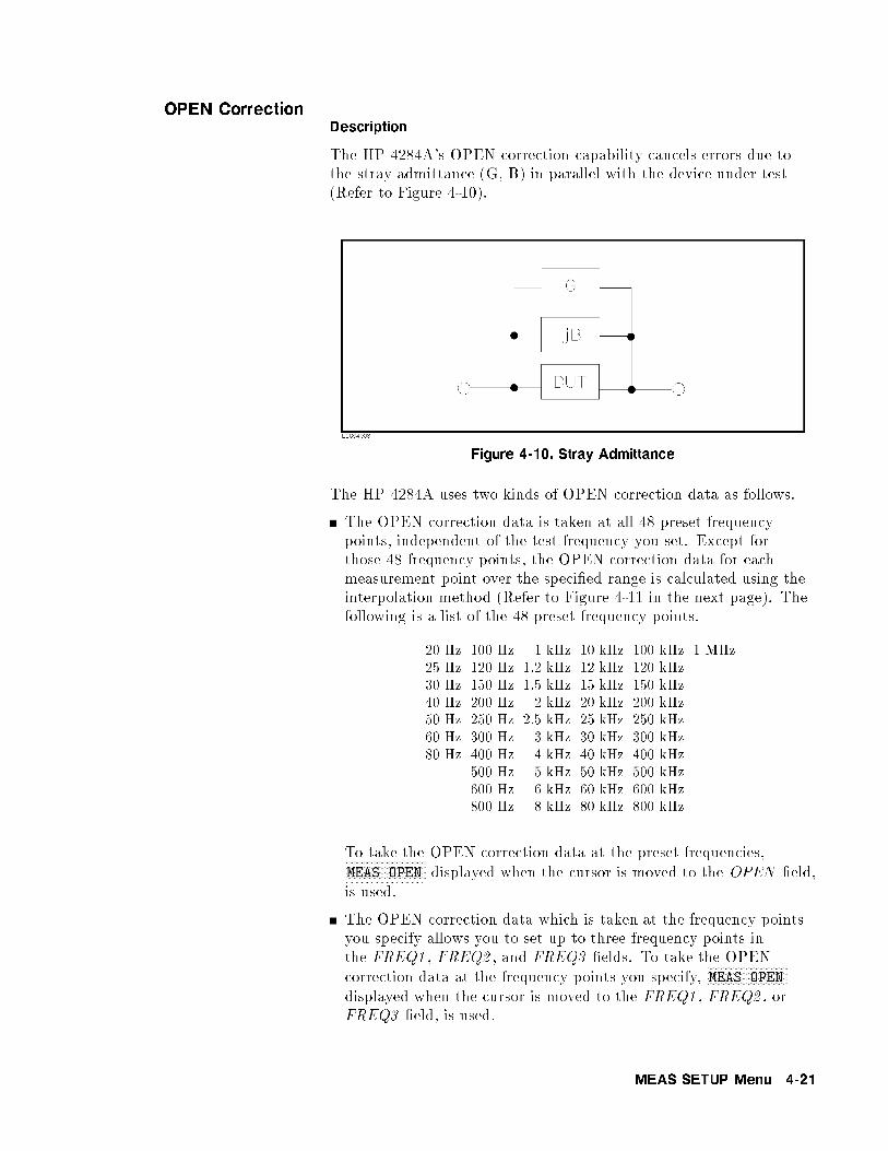
OPEN CorrectionDescription
The HP 4284A's OPEN correction capability cancels errors due tothe stray admittance (G, B) in parallel with the device under test(Refer to Figure 4-10).
Figure 4-10. Stray Admittance
The HP 4284A uses two kinds of OPEN correction data as follows.
The OPEN correction data is taken at all 48 preset frequencypoints, independent of the test frequency you set. Except forthose 48 frequency points, the OPEN correction data for eachmeasurement point over the speci�ed range is calculated using theinterpolation method (Refer to Figure 4-11 in the next page). Thefollowing is a list of the 48 preset frequency points.
20 Hz 100 Hz 1 kHz 10 kHz 100 kHz 1 MHz
25 Hz 120 Hz 1.2 kHz 12 kHz 120 kHz
30 Hz 150 Hz 1.5 kHz 15 kHz 150 kHz
40 Hz 200 Hz 2 kHz 20 kHz 200 kHz50 Hz 250 Hz 2.5 kHz 25 kHz 250 kHz60 Hz 300 Hz 3 kHz 30 kHz 300 kHz
80 Hz 400 Hz 4 kHz 40 kHz 400 kHz500 Hz 5 kHz 50 kHz 500 kHz600 Hz 6 kHz 60 kHz 600 kHz800 Hz 8 kHz 80 kHz 800 kHz
To take the OPEN correction data at the preset frequencies,NNNNNNNNNNNNNNNNNNNNNNNNNNNNNMEAS OPEN displayed when the cursor is moved to the OPEN �eld,
is used.
The OPEN correction data which is taken at the frequency pointsyou specify allows you to set up to three frequency points inthe FREQ1 , FREQ2 , and FREQ3 �elds. To take the OPEN
correction data at the frequency points you specify,NNNNNNNNNNNNNNNNNNNNNNNNNNNNNMEAS OPEN
displayed when the cursor is moved to the FREQ1 , FREQ2 , orFREQ3 �eld, is used.
MEAS SETUP Menu 4-21

Figure 4-11. OPEN/SHORT Correction Using The Interpolation Method
Front Panel Operation for the Open Correction
There are two procedures: OPEN correction using the interpolationmethod, and OPEN correction at the frequency points you specify.
Perform the following steps to execute the OPEN correction at allfrequency points using the interpolation method. When you want toexecute the OPEN correction at a single frequency point, refer to\LOAD Correction".
1. Move the cursor to the OPEN �eld. The following softkeys will bedisplayed.
NNNNNNNNONNNNNNNNNNNNOFFNNNNNNNNNNNNNNNNNNNNNNNNNNNNNMEAS OPEN
2. Connect your test �xture to the UNKNOWN Terminals withoutconnecting the device under test.
3. PressNNNNNNNNNNNNNNNNNNNNNNNNNNNNNMEAS OPEN . The HP 4284A will measure the OPEN
admittance (capacitance, and inductance) at the preset frequencypoints. The time required to measure the open correction data isapproximately 90 s. During the OPEN correction measurement,the following softkey is available.
NNNNNNNNNNNNNNNNNABORT
This softkey is used to stop an OPEN correction datameasurement. The previous OPEN correction data will still bestored.
4. PressNNNNNNNNON to perform the OPEN correction calculations on
subsequent measurements using the OPEN interpolation
4-22 MEAS SETUP Menu

correction data when the FREQ1 , FREQ2 , and FREQ3 �elds areset to OFF.
When the FREQ1 , FREQ2 , and FREQ3 �elds are set to ON, andthe test frequency is equal to FREQ1/2/3, the OPEN correctiondata at FREQ1/2/3 is used. (Refer to APPENDIX D.)
5. PressNNNNNNNNNNNOFF not to perform the OPEN correction calculations on
subsequent measurements.
SHORT CorrectionDescription
The HP 4284A's SHORT correction capability corrects for theresidual impedance (R, X) in serial with the device under test (Referto Figure 4-12).
Figure 4-12. Residual Impedance
The HP 4284A uses the following two kinds of SHORT correctiondata.
The SHORT correction data is taken at all 48 preset frequencypoints independent of the test frequency(ies) you set, and theSHORT correction data for each measurement point otherthan those present frequency points are calculated using theinterpolation method(Refer to Figure 4-11). All preset frequencypoints (48 frequency points) are as same as the preset frequenciesfor the OPEN correction using the interpolation method.
To take the SHORT correction data at the preset frequency points,NNNNNNNNNNNNNNNNNNNNNNNNNNNNNNNNMEAS SHORT , which is displayed when the cursor is moved to the
SHORT �eld, is used.
The SHORT correction data which is taken at the frequencypoints you specify. You can set up to three frequency points in theFREQ1 , FREQ2 , and FREQ3 �elds.
To take the SHORT correction data at the frequency points you
specify,NNNNNNNNNNNNNNNNNNNNNNNNNNNNNNNNMEAS SHORT , which is displayed when the cursor is moved
to the FREQ1 , FREQ2 , or FREQ3 �eld, is used.
MEAS SETUP Menu 4-23

Front Panel Operation for the Short Correction
There are two procedures: SHORT correction at all frequency points,and SHORT correction at user speci�ed frequency points.
Perform the following steps to execute the SHORT correction for allfrequency points. When you want to execute the short correction atthe user speci�ed frequency points, refer to \LOAD Correction".
1. Move the cursor to the SHORT �eld. The following softkeys willbe displayed.
NNNNNNNNONNNNNNNNNNNNOFFNNNNNNNNNNNNNNNNNNNNNNNNNNNNNNNNMEAS SHORT
2. Connect the test �xture to the UNKNOWN Terminals, and shortthe measurement contacts together.
PressNNNNNNNNNNNNNNNNNNNNNNNNNNNNNNNNMEAS SHORT . The HP 4284A will measure the short
impedance (inductance and resistance) at the preset frequencypoints. The time required to measure the short correction data isapproximately 90 s. During the SHORT correction measure cycle,the following softkey is available.
NNNNNNNNNNNNNNNNNABORT
This softkey is used to stop the short correction datameasurement. The previous SHORT correction data is stillstored.
3. PressNNNNNNNNON to perform SHORT correction calculations on
subsequent measurements when the FREQ1 , FREQ2 , and FREQ3
�elds are set to OFF.
When the FREQ1 , FREQ2 , and FREQ3 �elds are set to ON, andthe test frequency is equal to FREQ1/2/3, the SHORT correctiondata at FREQ1/2/3 is used. (Refer to Appendix D.)
4. PressNNNNNNNNNNNOFF to halt SHORT correction calculations on subsequent
measurements.
LOAD CorrectionDescription
The HP 4284A's LOAD correction capability corrects for theother errors by using the transmission coe�cient derived fromthe relationship between a standard's (premeasured) referencevalue to the actual measurement value at the frequency points youspecify (up to three frequency points). So, OPEN/ SHORT/LOADcorrections can be performed at the frequency points you specify(Refer to Figure 4-13). The three frequency points can be set in theFREQ1 ,FREQ2 , and FREQ3 �elds. The standard's reference valuesare set in the REF A, and B �elds. Before entering the standard'sreference values, the measurement function for the standard must
4-24 MEAS SETUP Menu

be set in the FUNC �eld. The standard's value can be measuredusing
NNNNNNNNNNNNNNNNNNNNNNNNNNNNNMEAS LOAD , which is displayed when the cursor is moved to the
FREQ1 , FREQ2 , or FREQ3 �elds.
Figure 4-13. OPEN/SHORT/LOAD Correction
Front Panel Operation for the OPEN/SHORT/LOAD Correction
Perform the following steps to perform the OPEN/ SHORT/LOADcorrection at the frequency points you want to specify.
1. Move the cursor to the FREQ1 , FREQ2 , or FREQ3 �eld tospecify the frequency for the OPEN/SHORT/LOAD correction.The following softkeys will be displayed.
NNNNNNNNON
This softkey is used to make the OPEN/SHORT/LOADcorrection data at the FREQ1, FREQ2, or FREQ3 frequencypoint valid.NNNNNNNNNNNOFF
This softkey is used to make the OPEN/SHORT/LOADcorrection data at the FREQ1, FREQ2, or FREQ3 frequencypoint invalid.NNNNNNNNNNNNNNNNNNNNNNNNNNNNNMEAS OPEN
This softkey is used to perform an OPEN correctionmeasurement at the FREQ1, FREQ2, or FREQ3 frequencypoints.NNNNNNNNNNNNNNNNNNNNNNNNNNNNNNNNMEAS SHORT
This softkey is used to perfom a SHORT correctionmeasurement at the FREQ1, FREQ2, or FREQ3 frequencypoints.NNNNNNNNNNNNNNNNNNNNNNNNNNNNNMEAS LOAD
This softkey is used to perform a LOAD correctionmeasurement at the FREQ1, FREQ2, or FREQ3 frequencypoints.
2. PressNNNNNNNNON to show the previous frequency for the
OPEN/SHORT/LOAD correction.
3. Enter the frequency using the numeric entry keys. When pressingone of the numeric entry keys, the softkey labels are changed to
MEAS SETUP Menu 4-25

the available units (NNNNNNNNHz ,
NNNNNNNNNNNkHz , and
NNNNNNNNNNNMHz ), so you can use these
softkeys to enter the unit and terminate the entry without hitting�ENTER�. (When �ENTER� is used, the numeric data is entered withHz.)
4. Connect the test �xture to the UNKNOWN Terminals.
|OPEN correction|
5. Leave the connection contacts open.
6. PressNNNNNNNNNNNNNNNNNNNNNNNNNNNNNMEAS OPEN . The HP 4284A performs an OPEN correction
measurement at the frequency points you speci�ed. After which,the OPEN correction measurement data are displayed on thesystem message line.
7. Move the cursor to the OPEN �eld.
8. PressNNNNNNNNON to perform the OPEN correction calculations for
subsequent measurements at the speci�ed frequency points.
|SHORT correction|
9. Move the cursor to the FREQ1 , FREQ2 , or FREQ3 �eld atwhich you speci�ed the frequency.
10. Short the connection contacts ogether.t
11. PressNNNNNNNNNNNNNNNNNNNNNNNNNNNNNNNNMEAS SHORT . The HP 4284A will perform a SHORT
correction measurement, and display the SHORT correction dataon the system message line.
12. Move the cursor to the SHORT �eld.
13. PressNNNNNNNNON to perform the SHORT correction calculations for
subsequent measurements at the speci�ed frequency points.
|LOAD correction|
14. Prepare the standard for measurement.
15. Move the cursor to the FUNC �eld.
16. Set the measurement function for your standard. (Refer to thenext paragraph (Measurement function for the standard.))
17. Move the cursor to the REF A �eld of your speci�ed frequency.
18. Enter the premeasured value of your standard's primaryparameter using the numeric entry keys and the unit softkeys.
19. Move the cursor to the B �eld on the right side of your set REFA �eld.
20. Enter your standard's premeasured secondary parameter valueusing the numeric entry keys and the unit softkeys.
21. Move the cursor to the FREQ1 , FREQ2 or FREQ3 �eld atwhich you speci�ed the frequency.
22. Connect the standard to the measurement contacts.
4-26 MEAS SETUP Menu

23. PressNNNNNNNNNNNNNNNNNNNNNNNNNNNNNMEAS LOAD . The HP 4284A will perform a LOAD
correction measurement, and display the LOAD correction dataon the system message line.
24. Move the cursor to the LOAD �eld.
25. PressNNNNNNNNON to enable the LOAD correction calculations for
subsequent measurements at the speci�ed frequency points.
Note The relationship between the CORRECTION page andOPEN/SHORT/LOAD correction function are as follows.
1 This area is used as follows.
To perform the OPEN/SHORT/LOAD correction calculationsusing either the OPEN/SHORT interpolation correction data orthe OPEN/SHORT/LOAD correction data at the spot frequencyyou specify. This correction data selection depends on the testfrequency.
To obtain the OPEN/SHORT interpolation correction data.
2 This area is used as follows.
To obtain the OPEN/SHORT/LOAD correction data at the spotfrequencies you specify (FREQ1, FREQ2, or FREQ3).
To make the OPEN/SHORT/LOAD correction data at the spotfrequencies you specify (FREQ1, FREQ2, or FREQ3) valid orinvalid.
The correction data used depends on the test frequency as follows.(For more detail, refer to APPENDIX D.)
MEAS SETUP Menu 4-27

Correction
Mode
Test Frequency
6= FREQ1{3Test Frequency
= FREQ1{3
FREQ1{3OFF
FREQ1{3ON
FREQ1{3OFF
FREQ1{3ON
OPEN: ON INTPOL INTPOL INTPOL SPOT
SHORT: ON INTPOL INTPOL INTPOL SPOT
LOAD: ON � � � SPOT
SPOT: The correction data for the frequency points youspeci�ed is used.
INTPOL: Interpolation correction data is used.
�: Correction isn't performed even if the correctionfunction is set to ON in the OPEN , SHORT , orLOAD �elds.
When the frequency you specify is equal to a frequency alreadyspeci�ed, the following correction data is used.
Test Frequency = FREQ1 = FREQ2
Correction data: Data at FREQ1
Test Frequency = FREQ2 = FREQ3
Correction data: Data at FREQ2
Test Frequency = FREQ1 = FREQ2 = FREQ3
Correction data: Data at FREQ1
Measurement Functionfor the Standard Description
When the LOAD correction is performed, the reference(pre-measured) value of the standard must be entered. The referencevalue should be the premeasured value of the following measurementfunctions.
Cp-D Lp-D R-XCp-Q Lp-Q Z-� (deg)
Cp-G Lp-G Z-� (rad)
Cp-Rp Lp-Rp G-BCs-D Ls-D Y-� (deg)
Cs-Q Ls-Q Y-� (rad)
Cs-Rs Ls-Rs
The LOAD correction corrects the errors using the transmissioncoe�cient derived from the relationship between the standard'sreference value and the actual raw measurement value. The abovefunction is used only for calculating the transmission coe�cient.
4-28 MEAS SETUP Menu

Front Panel Operation for Setting the Standard's Measurement
Function
Perform the following steps to set the measurement function for thestandard.
1. Move the cursor to the FUNC �eld. The following softkeys willdisplayed.
NNNNNNNNNNNNNNCp-DNNNNNNNNNNNNNNCp-QNNNNNNNNNNNNNNCp-GNNNNNNNNNNNNNNNNNCp-RpNNNNNNNNNNNNNNNNNNNNNNNNNNmore 1/6
2. Select and press a softkey to set the measurement function. Ifthe measurement function softkey you want isn't displayed, pressNNNNNNNNNNNNNNNNNNNNNNNNNNmore 1/6 . The following softkeys will be displayed.
NNNNNNNNNNNNNNCs-DNNNNNNNNNNNNNNCs-QNNNNNNNNNNNNNNNNNCs-RsNNNNNNNNNNNNNNNNNNNNNNNNNNmore 2/6
3. Select and press a softkey to set the measurement function. Ifthe measurement function softkey you want isn't displayed, pressNNNNNNNNNNNNNNNNNNNNNNNNNNmore 2/6 . The following softkeys will be displayed.
NNNNNNNNNNNNNNLp-DNNNNNNNNNNNNNNLp-QNNNNNNNNNNNNNNLp-GNNNNNNNNNNNNNNNNNLp-RpNNNNNNNNNNNNNNNNNNNNNNNNNNmore 3/6
4. Select and press a softkey to set the measurement function. Ifthe measurement function softkey you want isn't displayed, pressNNNNNNNNNNNNNNNNNNNNNNNNNNmore 3/6 . The following softkeys will be displayed.
NNNNNNNNNNNNNNLs-DNNNNNNNNNNNNNNLs-QNNNNNNNNNNNNNNNNNLs-RsNNNNNNNNNNNNNNNNNNNNNNNNNNmore 4/6
5. Select and press a softkey to set the measurement function. Ifthe measurement function softkey you want isn't displayed, pressNNNNNNNNNNNNNNNNNNNNNNNNNNmore 4/6 . The following softkeys will be displayed.
NNNNNNNNNNNR-X
MEAS SETUP Menu 4-29

NNNNNNNNNNNNNNNNNNNNNNNNNNNNNZ-� (deg)NNNNNNNNNNNNNNNNNNNNNNNNNNNNNZ-� (rad)NNNNNNNNNNNNNNNNNNNNNNNNNNmore 5/6
6. Select and press a softkey to set the measurement function. If the
measurement function softkey isn't displayed, pressNNNNNNNNNNNNNNNNNNNNNNNNNNmore 5/6 .
The following softkeys will be displayed.NNNNNNNNNNNG-BNNNNNNNNNNNNNNNNNNNNNNNNNNNNNY-� (deg)NNNNNNNNNNNNNNNNNNNNNNNNNNNNNY-� (rad)NNNNNNNNNNNNNNNNNNNNNNNNNNmore 6/6
7. Select and press a softkey to set the measurement function.
4-30 MEAS SETUP Menu

Single/Multi CorrectionMode Selection Description
When the Option 301 (Scanner Interface) is installed, the HP 4284Acan store up to 128 sets of OPEN, SHORT, LOAD correctionmeasurement data, and one LOAD correction reference data for eachof the three test frequencies (FREQ1, FREQ2, and FREQ3), andthis correction mode is the MULTI correction mode. (The normalcorrection mode is the SINGLE correction mode.)
Note When the MULTI correction mode is used, the OPEN/SHORTcorrection using the interpolation method cannot be performed.(Only the OPEN/SHORT/LOAD correction at the frequencies youspecify can performed.)
The FREQ1, FREQ2, and FREQ3 frequency points are dependenton the correction mode (SINGLE, MULTI).
This MODE �eld allows you to select the single correction mode orthe multi correction mode. For more information about the multicorrection mode, refer to Chapter 3, option 301. scanner interfaceoperation note.
In the case of the multi correction mode, the channel number forselecting the correction data is displayed at the CH No. monitorarea.
Front Panel Operation for Setting the Correction Mode to the Multi
Correction Mode
1. Press �CATALOG/SYSTEM�, andNNNNNNNNNNNNNNNNNNNNNNNNNNNNNNNNNNNNNNNNNSYSTEM CONFIG to display the
SYSTEM CONFIG page.
2. Move the cursor to the SCANNER INTERFACE SETTING �eld.
3. PressNNNNNNNNON to make the scanner interface function valid.
4. Press �MEAS SETUP�, andNNNNNNNNNNNNNNNNNNNNNNNNNNNNNNNNCORRECTION to return to the
CORRECTION page.
5. Move the cursor to the MODE �eld. The following softkeys willbe displayed.
NNNNNNNNNNNNNNNNNNNNSINGLENNNNNNNNNNNNNNNNNMULTI
6. PressNNNNNNNNNNNNNNNNNMULTI to select the multi correction mode. If you want to
set the single correction mode, pressNNNNNNNNNNNNNNNNNNNNSINGLE .
MEAS SETUP Menu 4-31

Cable Length SelectionDescription
The HP 4284A has two reference planes|to the UNKNOWNTerminals (0m), and to the end of the HP 16048A/B test leads (1m).When Option 006 (2m/4m Cable Length Operation) is installed, theHP 4284A has four reference planes|to the UNKNOWN Terminals(0m), to the end of the HP 16048A/B Test Leads (1m), to the endof the HP 16048D test leads (2m), and to the end of the HP 16048Etest leads (4m). Measurement accuracy is speci�ed at these points.
When you select 0m, the four outer conductors of the HPOT, HCUR,LPOT, and LCUR test leads must be tied together at the UNKNOWNterminals.
When you select 1m, the four outer conductors of the HPOT, HCUR,LPOT, and LCUR test leads must be tied together at the end of theHP 16048A/B 1m leads.
When you select 2m, the four outer conductors of the test leads mustbe tied together at the end of the HP 16048D 2m test leads.
When you select 4m, the four outer conductors of the HPOT, HCUR,LPOT, and LCUR test leads must be tied together at the end of theHP 16048E 4m test leads.
In other words, the four-terminal pair con�guration mustbe terminated for the cable length selected. When anHP 16048A/B/D/E test leads are used, use the furnished terminalplate at the end of the cable for easy con�guration.
Front Panel For Selecting the Cable Length
Perform the following steps to select the cable length.
1. Move the cursor to the CABLE �eld. The following softkeys willbe displayed.
NNNNNNNNNNN0 mNNNNNNNNNNN1 mNNNNNNNNNNN2 mNNNNNNNNNNN4 m
2. Select and press a softkey to select the cable length.
System Menu The system menu on this page allows you to perform the followingcontrol functions.
Printer
This function is the same as the functions on the system menu on theMEAS DISPLAY page. (A description of this function is given in\System Menu" in Chapter 3.) So only the procedure is given in thefollowing paragraphs.
4-32 MEAS SETUP Menu

Printer Function
Perform the following steps to print out the information of theCORRECTION page using the PRINT DISP mode.
1. Connect the HP 4284A to the printer using an HP-IB cable.
2. Set the printer to the Listen Only mode.
3. Set the Talk Only mode to ON from the SYSTEM CONFIG page.
4. Press �MEAS SETUP�, andNNNNNNNNNNNNNNNNNNNNNNNNNNNNNNNNCORRECTION to display the
CORRECTION page.
5. Move the cursor to the SYS MENU �eld.
6. PressNNNNNNNNNNNNNNNNNNNNNNNNNNNNNNNNPRINT DISP to print out the display page. The display
page is printed out to the printer as shown in Figure 4-14.
<CORRECTION> SYS MENU
OPEN : ON CABLE : 0 m
SHORT: ON MODE : MULTI
LOAD : ON CH No.: 0
FUNC : Cp-D
FREQ1 :1.00000kHz
REF A: 100.000pF B: .000000
MEA A: 99.6222pF B: .008178
FREQ2 :2.00000kHz
REF A: 100.000pF B: .000000
MEA A: 99.8350pF B: .003234
FREQ2 :1.00000MHz
REF A: 100.000pF B: .000003
MEA A: 99.9439pF B: .000266
Figure 4-14. CORRECTION Page Example
LIMIT TABLE SETUPPage
When you press �MEAS SETUP�, andNNNNNNNNNNNNNNNNNNNNNNNNNNNNNNNNNNNLIMIT TABLE , the LIMIT TABLE
SETUP page will be displayed. The LIMIT TABLE SETUP pageallows you to set the HP 4284A's comparator. The HP 4284A'sbuilt-in comparator can sort devices into a maximum of ten bins(BIN 1 to BIN 9 and one OUT OF BINS) using a maximum of ninepairs of primary limits and one pair of secondary parameter limits.Also, devices whose primary parameter is within limits, but whosesecondary parameter measurement result not within limits, can besorted into an AUXiliary BIN. The comparator function is especiallyuseful when using the HP 4284A with a component handler (handlerinterface option is installed). These limit settings for bin sorting areonly set on this LIMIT TABLE SETUP page.
Measurement Function (FUNC )Comparator Function's Limit Mode (MODE)
MEAS SETUP Menu 4-33

Nominal Value for tolerance mode (NOMINAL)Auxiliary bin ON/OFF (AUX )Comparator Function ON/OFF (COMP )Low Limit Value of each bin (LOW )High Limit Value of each bin (HIGH )
Each function is described in the following paragraphs.
The available �elds and the softkeys which correspond to the �eldson this page are shown in Figure 4-15 and Figure 4-16.
4-34 MEAS SETUP Menu

Figure 4-15. Available Fields on the LIMIT TABLE SETUP Page
MEAS SETUP Menu 4-35
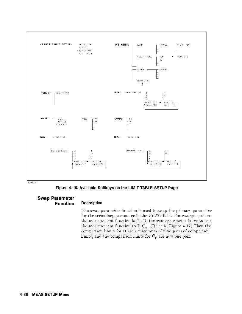
Figure 4-16. Available Softkeys on the LIMIT TABLE SETUP Page
Swap ParameterFunction Description
The swap parameter function is used to swap the primary parameterfor the secondary parameter in the FUNC �eld. For example, whenthe measurement function is Cp-D, the swap parameter function setsthe measurement function to D-Cp. (Refer to Figure 4-17) Then thecomparison limits for D are a maximum of nine pairs of comparisonlimits, and the comparison limits for Cp are now one pair.
4-36 MEAS SETUP Menu

Figure 4-17. Swap Parameter Function
Front Panel Operation for Swapping the Primary Parameter for the
Secondary Parameter
Perform the following steps to swap the primary parameter for thesecondary parameter.
1. Move the cursor to the FUNC �eld. The following softkey will bedisplayed.
NNNNNNNNNNNNNNNNNNNNNNNNNNNNNNNNSWAP PARAM
2. PressNNNNNNNNNNNNNNNNNNNNNNNNNNNNNNNNSWAP PARAM to swap the primary parameter for the
secondary parameter.
3. PressNNNNNNNNNNNNNNNNNNNNNNNNNNNNNNNNSWAP PARAM again to return the measurement function to
the previous combination.
Limit Mode forComparator Description
There are two methods for specifying primary parameter limits, asfollows. (Refer to Figure 4-18)
Tolerance Mode The tolerance mode speci�es comparison limits bythe deviation from the speci�ed nominal value. (The nominal valueis speci�ed at NOM �eld.) There are two methods used to specifythe tolerance mode limits, the ratio in percent and by parametervalue.
Sequential Mode The sequential mode speci�es comparison limitsas the absolute measurement value. The limits must be set in orderfrom the smallest value to the largest value.
MEAS SETUP Menu 4-37
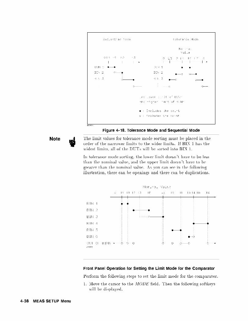
Figure 4-18. Tolerance Mode and Sequential Mode
Note The limit values for tolerance mode sorting must be placed in theorder of the narrower limits to the wider limits. If BIN 1 has thewidest limits, all of the DUTs will be sorted into BIN 1.
In tolerance mode sorting, the lower limit doesn't have to be lessthan the nominal value, and the upper limit doesn't have to begreater than the nominal value. As you can see in the followingillustration, there can be openings and there can be duplications.
Front Panel Operation for Setting the Limit Mode for the Comparator
Perform the following steps to set the limit mode for the comparator.
1. Move the cursor to the MODE �eld. Then the following softkeyswill be displayed.
4-38 MEAS SETUP Menu

NNNNNNNNNNNNNNNNN% TOL
This softkey is used to set the limit mode to the tolerance mode(the ratio in percent).NNNNNNNNNNNNNNNNNNNNNNNABS TOL
This softkey is used to set the limit mode to the tolerance mode(parameter value).NNNNNNNNNNNSEQ
This softkey is used to set the limit mode to the sequentialmode.
2. Select and set the limit mode using the softkeys.
Nominal Value forTolerance Mode Description
When the tolerance mode is used as a limit mode for the primaryparameter, the nominal value must be set. The nominal value canbe set within the range of the following measurement range of theprimary parameter.
Primary Parameter and Display Range
Parameter Range
jZj, R, X 0.01 m to 99.9999 M
jYj, G, B 0.01 nS to 99.9999 S
C 0.01 fF to 9.99999 F
L 0.01 nH to 99.9999 kH
D 0.000001 to 9.99999
Q 0.01 to 99999.9
� �180.000 � to 180.000 �
When the limit mode for the primary parameter is the sequentialmode, the nominal value can be set, but this has no meaning in thesequential mode.
Front Panel Operation for Setting the Nominal Value
Perform the following steps to set the nominal value.
1. Move the cursor to the NOM �eld.
2. Enter the nominal value using the numeric entry keys. When the
numeric data is entered, the su�x softkeys (NNNNNp ,
NNNNNn ,
NNNNN� ,
NNNNNm ,
NNNNNk ,
NNNNNM )
can be used instead of �ENTER�.
MEAS SETUP Menu 4-39

Comparator FunctionON/OFF Description
The HP 4284A's built-in comparator can sort devices into amaximum of ten bins (BIN 1 to BIN 9 and the OUT OF BINS bin)using a maximum of nine pairs of primary limits and one pair ofsecondary parameter limits. Also, a device whose primary parameteris within limits, but whose secondary parameter measurement resultis not within limits can be sorted into the AUXiliary BIN. Thecomparator function is especially useful when using the HP 4284Awith a component handler (handler interface option is installed).
Front Panel Operation for Setting the Comparator Function to ON or
OFF
Perform the following steps to set the comparator function to ON orOFF.
1. Move the cursor to the COMP �eld. The following softkeys willbe displayed.
NNNNNNNNON
NNNNNNNNNNNOFF
2. Use the softkeys to set the comparator function to ON or OFF.
4-40 MEAS SETUP Menu

Auxliary Bin ON/OFFDescription
When the secondary parameters a�ect the sorting results, the limitsfor the secondary parameter can be set in 2nd LOW/HIGH �elds.So there are three patterns for the sorting area of the secondaryparameter.
When the secondary parameter limits are not speci�ed on theLIMIT TABLE SETUP page.
Devices will be sorted according to primary parameter comparisonresults.
When the secondary parameter limits are set and AUX BIN are setto OFF.
Only devices with secondary limits are sorted by the primaryparameter result. Devices not within the secondary parameterlimits are sorted OUT OF BINS even if the device's primaryparameter is within limits.
MEAS SETUP Menu 4-41

When the secondary parameter limits are set and AUX BIN are setto ON.
Devices whose primary parameter is not within limits are sortedOUT OF BINS. Devices whose primary parameter is within limits,but whose secondary parameter is out of limits are sorted into theAUX BIN.
Note When only the lower limit of the secondary parameter is set and theAUX BIN are set to ON, the devices whose primary parameter iswithin limits, but whose secondary parameter is equal to or belowthe lower limit are sorted into the AUX BIN. Also when only thehigher limit of the secondary parameter is set and the AUX BIN areset to ON, the devices whose primary paramter is within limits, butwhose secondary parameter is equal or above the higher limit aresorted into the AUX BIN. (See below.)
The AUX �eld allows you to set the AUX BIN to ON or OFF.
Front Panel Operation for Setting the AUX BIN to ON or OFF
Perform the following steps to set the AUX BIN to ON or OFF.
1. Move the cursor to the AUX �eld. The following softkeys will bedisplayed.
4-42 MEAS SETUP Menu

NNNNNNNNONNNNNNNNNNNNOFF
2. Select and press a softkey to set AUX BIN to ON or OFF.
Low/High LimitsDescription
The HP 4284A's built-in comparator can sort devices into amaximum of ten bins (BIN 1 to BIN 9, and OUT OF BINS) usinga maximum of nine pairs of primary parameter limits and one pairof secondary parameter limits. These primary parameter low/highlimits can be set in the BIN 1 to BIN 9 LOW/HIGH �elds, andthe secondary parameter low/high limits can be set in the 2ndLOW/HIGH �elds.
Note Do NOT enter a value which is lower than the LOW limit into theHIGH limit in the tolerance sorting mode. If you do, the warningmessage Warning, Improper high/low limits will be displayed (thisisn't an error), and the HP 4284A will not sort a DUT into the BINsyou specify.
The limit values for sequential mode sorting can be set withoutsetting the lower/higher limits of BIN1. For example,
BIN 1: Low Limit (L1) onlyBIN 2: High Limit (H2)BIN 3: High Limit (H3)
BIN 1: High Limit (H1) onlyBIN 2: High Limit (H2)BIN 3: High Limit (H3)
MEAS SETUP Menu 4-43

BIN 2: High Limit (H2)BIN 3: High Limit (H3)
Front Panel Operation for Setting the Low/High Limits
Perform the following steps to set the bin sorting limits.
1. Set the measurement function for the comparator function,the nominal value, and the the limit mode for the primaryparameter.
2. Move the cursor to the SYS MENU �eld, and perform the cleartable function.
3. Move the cursor to the BIN 1 LOW �eld. When you use thetolerance mode, perform steps 4 through 7. When you use thesequential mode, perform steps 8 through 12.
|Tolerance Mode is used|
4. Enter the limit value of the BIN 1 at BIN 1 LOW �eld usingthe numeric entry keys. When one of the numeric entry keys
is pressed, the su�x softkeys (NNNNNp ,
NNNNNn ,
NNNNN� ,
NNNNNm ,
NNNNNk , and
NNNNNM ) are
available, and so you can use these softkeys to enter the unit andterminate the entry without hitting �ENTER�. When the limitvalue of BIN 1 is entered in the BIN 1 LOW �eld, the BIN 1 lowlimit becomes � (absolute input value), and the BIN 1 high limitbecomes + (absolute input value).
5. The cursor will be automatically moved to the BIN 2 LOW �eld.Repeat step 4 until the limits of the BIN 9 is entered. After that,the cursor will be moved to the 2nd LOW �eld.
6. Enter the low limit value of the secondary parameter. After that,the cursor will be automatically moved to the 2nd HIGH �eld.
7. Enter the high limit value of the secondary parameter. Then theentry example using the tolerance mode is shown in Figure 4-16.
|Sequential Mode is used|
8. Enter the low limit of the BIN 1 using the numeric entry keys.When the one of the numeric entry keys is pressed, the su�x
soft-keys (NNNNNp ,
NNNNNn ,
NNNNN� ,
NNNNNm ,
NNNNNk , and
NNNNNM ) are available, so you can use
4-44 MEAS SETUP Menu

these softkeys to enter the unit and terminate the entry withouthitting �ENTER�.
9. The cursor will be automatically moved to the BIN 1 HIGH �eldafter entering the low limit of the BIN 1. Enter the high limit ofthe BIN 1.
10. The cursor will be automatically moved to the BIN 2 HIGH
�eld. Because the BIN 2 low limit value is as same as the BIN 1high limit value. Enter the high limit of the BIN 2.
11. Repeat step 5 until the BIN 9 limits are entered. After enteringthe BIN 9 high limit, the cursor will be automatically moved tothe 2nd LOW �eld. Enter the low limit value of the secondaryparameter.
12. The cursor will be automatically moved to the 2nd HIGH �eld.Enter the high limit value of the secondary parameter. The entryexample using the sequential mode is shown below.
Figure 4-19. Limit Table Using the Sequential Mode
System Menu The system menu on this page allows you to perform the followingcontrol functions.
Load/StoreClear TablePrinter
These functions, except for the clear table function, are the sameas the functions in the system menu on the MEAS DISPLAY
page. (A description of each function is given in \System Menu"in Chapter 3.) So, in the case of the clear table function, thedescription and procedure are given, and in the case of the otherfunctions, only the procedure is given.
MEAS SETUP Menu 4-45

Load/Store Function
Perform the following steps on the LIMIT TABLE SETUP page toLoad/Store the control settings to the internal non-volatile memoryor to the external memory card.
1. Set all controls.
2. Move the cursor to the SYS MENU �eld on the LIMIT TABLE
SETUP page.
3. Insert the memory card to the MEMORY card slot, if you areusing a memory card.
4. PressNNNNNNNNNNNNNNNNNSTORE when you want to use the store function. The
message Enter record number to STORE will be displayed on thesystem message line.
PressNNNNNNNNNNNNNNLOAD when you want to use the load function. The message
Enter record number to LOAD will be displayed on the systemmessage line.
5. Enter the record number using the numeric entry keys and �ENTER�to store the current control settings, or load the control settings.
Clear Table Function
This function allows you to clear all of the limit values. So, when youchange the limit mode, this function must be used.
Perform the following steps to clear all of bin sorting limits on theLIMIT TABLE SETUP page.
1. Move the cursor to the SYS MENU �eld.
2. PressNNNNNNNNNNNNNNNNNNNNNNNNNNNNNNNNNNNCLEAR TABLE . The message Clearing table, Are you
sure? will be displayed, and the following softkeys will bedisplayed.
NNNNNNNNNNNYESNNNNNNNNNO
3. PressNNNNNNNNNNNYES to clear all of the bin sorting limits.
4-46 MEAS SETUP Menu

Printer Function
Perform the following steps to print out the display page using thePRINT DISP mode.
1. Connect the HP 4284A to the printer using the HP-IB cable.
2. Set the printer to the Listen Only mode.
3. Set the talk only mode to ON on the SYSTEM CONFIG page.
4. Press �MEAS SETUP� andNNNNNNNNNNNNNNNNNNNNNNNNNNNNNNNNNNNLIMIT TABLE to display the LIMIT
TABLE SETUP page.
5. Move the cursor to the SYS MENU �eld.
6. PressNNNNNNNNNNNNNNNNNNNNNNNNNNmore 1/2 .
7. PressNNNNNNNNNNNNNNNNNNNNNNNNNNNNNNNNPRINT DISP . The display page is printed out to the printer
as shown in Figure 4-20.
<LIMIT TABLE SETUP> SYS MENU
FUNC: Cp-D NOM: 100.000pF
MODE: % AUX: ON COMP: ON
BIN LOW HIGH
1 - 0.001 % + 0.001 %
2 - 0.002 % + 0.002 %
3 - 0.005 % + 0.005 %
4 - 0.010 % + 0.010 %
5 - 0.020 % + 0.020 %
6 - 0.050 % + 0.050 %
7 - 0.100 % + 0.100 %
8 - 0.200 % + 0.200 %
9 - 0.500 % + 0.500 %
2nd +.000000 +.000010
Figure 4-20. LIMIT TABLE SETUP Page Example
MEAS SETUP Menu 4-47

LIST SWEEP SETUPPage
When you press �MEAS SETUP� andNNNNNNNNNNNNNNNNNNNNNNNNNNNNNNNNLIST SETUP , the LIST SWEEP
SETUP page will be displayed. The HP 4284A has a list sweepmeasurement function which permits up to ten test frequencies,oscillator levels, or DC bias points to be automatically measured. Onthe LIST SWEEP SETUP page, the following control settings of thelist sweep measurement can be set. (Each �eld in parenthesis is usedwhen that control is set.)
Sweep Mode (MODE)
Sweep Parameter Selection (FREQ[Hz] , LEVEL[V] , LEVEL[A] ,BIAS[V] , or BIAS[A] )
Sweep Point Settings (sweep point)
Limit Parameter Selection (LMT )
Low/High Limit Values (LOW , HIGH )
There are following �elds on this page: <LIST SWEEP SETUP>,MODE , FREQ [Hz] (LEVEL [V] , LEVEL [A] , BIAS [V] , or BIAS[A] ), LMT , LOW/HIGH , SYS MENU , and sweep points.
These functions are described in the following paragraphs.
The available �elds and softkeys which corresponded to the �elds onthis page are shown in Figure 4-21 and Figure 4-22.
4-48 MEAS SETUP Menu

Figure 4-21. Available Fields on the LIST SWEEP SETUP Page
MEAS SETUP Menu 4-49

Figure 4-22. Available Softkeys on the LIST SWEEP SETUP Page
Sweep ModeDescription
The HP 4284A has a List Sweep measurement function whichpermits up to 10 test frequencies, oscillator levels, or DC bias pointsto be automatically measured. There are two sweep modes for thelist sweep measurements: sequential (SEQ) mode and step (STEP)mode. In the case of the sequential mode, when the HP 4284A istriggered once, the device is automatically measured at all sweeppoints. In the case of the step mode, the sweep point is incrementedeach time the HP 4284A is triggered.
4-50 MEAS SETUP Menu

Figure 4-23. SEQ mode and STEP mode
Note When two or more sweep points are the same, and are adjacent theHP 4284A measures the device once, and then the measurementresult is compared to limits set for each sweep point.
Front Panel Operation for Setting the List Sweep Measurement Mode
Perform the following steps to set the list sweep measurement modeto the sequential mode, or to the step mode.
1. Move the cursor to the MODE �eld. The following softkeys willbe displayed.
NNNNNNNNNNNSEQNNNNNNNNNNNNNNSTEP
2. Select and press a softkey to set the list sweep measurement mode.
List Sweep ParameterDescription
The sweep point parameter for the list sweep measurement can be setto the test frequency, oscillator level, and DC bias. This �eld allowsyou to set the parameter of the list sweep measurement.
Front Panel Operation for Setting the List Sweep Parameter
Perform the following steps to set the list sweep parameter.
1. Move the cursor to the FREQ [Hz] (LEVEL [V] , LEVEL [A] ,BIAS [V] , or BIAS [A] ) �eld. The following softkeys will bedisplayed.
NNNNNNNNNNNNNNNNNNNNNNNNNNNNNFREQ [Hz]NNNNNNNNNNNNNNNNNNNNNNNNNNNNNLEVEL [V]NNNNNNNNNNNNNNNNNNNNNNNNNNNNNLEVEL [A]NNNNNNNNNNNNNNNNNNNNNNNNNNBIAS [V]
MEAS SETUP Menu 4-51

NNNNNNNNNNNNNNNNNNNNNNNNNNBIAS [A]
2. Select and press a softkey to set the list sweep measurement sweepparameter.
Sweep Points and LimitMode Description
The list sweep function permits entry of up to 10 points andmeasurement limits. Figure 4-24 shows the available �elds for settingthe sweep points, the limit parameter, and the high/low limit values.
Figure 4-24. List Sweep Settings
Note When only the low limits of the sweep points are set, the deviceswhose selected parameter's data are equal, or are above the lowlimits are sorted as IN. When only the high limits of the sweep pointsare set, the devices whose selected parameter's data are equal, or arebelow the high limits are sorted as IN.
Note The comparison results are always IN when the paramter selectionfor the limit function is performed, but the low/high limit valuesaren't entered.
Note The comparison results is always LOW under the followingconditions (which are equal to the condition at <STATUS> 6= 0 inthe data format.)
Analog Bridge is unbalanced.A/D converter isn't working.Signal source is overloaded.ALC is unable to regulate.
4-52 MEAS SETUP Menu

Note Do NOT enter a value which is lower than the LOW limit into theHIGH limit. If you do, the warning message Warning, Improper
high/low limits will be displayed (this isn't an error). Thecomparison results are as follows.
Measurement results < LOW limit
Result: LOWMeasurement results � LOW limit
Result: HIGH
Front Panel Operation for Setting the Sweep Points
Perform the following steps to set the sweep points and measurementlimits.
1. Move the cursor to the sweep parameter �eld and set the sweepparameter.
2. Move the cursor to the sweep point �eld.
3. Enter the sweep point using the numeric entry keys. When the
one of the numeric entry keys is pressed, the unit softkeys (NNNNN� ,
NNNNNm ,
NNNNNk , and
NNNNNM ) are available, so you can use these softkeys to enter the
unit and terminate the entry without hitting �ENTER�.
4. The cursor will move automatically to the LMT �eld after youenter a sweep point. The following softkeys will be displayed.
NNNNNNNNNNNNNNNNNNNNNNNNNNNNNNNNNNNNNNLIMIT DATA A
This softkey is used to set the limit parameter to the primaryparameter of the measurement function. When this softkey ispressed, the cursor will automatically move to the LOW �eld.NNNNNNNNNNNNNNNNNNNNNNNNNNNNNNNNNNNNNNLIMIT DATA B
This softkey is used to set the limit parameter to the secondaryparameter of the measurement function. When this softkey ispressed, the cursor will move automatically to the LOW �eld.NNNNNNNNNNNOFF
This softkey is used to set the list sweep measurement's limitfunction to OFF for the sweep point. When this softkey ispressed, the cursor will move automatically to the next sweeppoint �eld.
5. Press the softkey to set the limit parameter.
6. The cursor will move automatically to the LOW �eld. (If
you pressedNNNNNNNNNNNOFF in the previous step, the cursor will move
automatically to the next sweep point �eld.) Enter the low limitvalue.
7. The cursor will move automatically to the HIGH �eld. Enter thehigh limit value using the numeric entry keys. After entering the
MEAS SETUP Menu 4-53

high limit value, the cursor will move automatically to the nextsweep point �eld. Repeat steps 3 through 7.
System Menu The system menu on this page allows you to perform the followingcontrol functions.
Load/StoreClear TablePrinter
These functions, except for the clear table function, are the sameas the functions in the system menu on the MEAS DISPLAY
page. (A description of each function is given in \System Menu" inChapter 3 on page 3-19.) So in the case of the clear table function,the description and procedure are given, and in the case of the otherfunctions, only the procedure is given.
Load/Store Function
Perform the following steps on the LIST SWEEP SETUP page toLoad/Store the control settings from/to internal non-volatile memoryor an external memory card.
1. Set all controls.
2. Move the cursor to the SYS MENU �eld on the LIST SWEEP
SETUP page.
3. If you are using a memory card insert the memory card to theMEMORY card slot.
4. PressNNNNNNNNNNNNNNNNNSTORE when you want to use the store function. The
message Enter record number to STORE will be displayed on thesystem message line.
PressNNNNNNNNNNNNNNLOAD when you want to use the load function. The message
Enter record number to LOAD will be displayed on the systemmessage line.
5. Enter the record number using the numeric entry keys and �ENTER�to Load/Store the current control settings.
Clear Table Function
This function allows you to clear all of the list sweep points andlimits. When you change from the current sweep parameter to theother sweep parameter, this function must be used.
Perform the following steps to set only all of the operations on theLIST SWEEP SETUP page to the power on default settings.
1. Move the CURSOR to the SYS MENU �eld.
2. PressNNNNNNNNNNNNNNNNNNNNNNNNNNNNNNNNNNNCLEAR TABLE . Then the message Clearing table, Are
you sure? will be displayed, and the following softkeys will bedisplayed.
4-54 MEAS SETUP Menu

NNNNNNNNNNNYESNNNNNNNNNO
3. PressNNNNNNNNNNNYES to clear all of the list sweep points and limits.
Printer Function
Perform the following steps to print out the display page using thePRINT DISP mode.
1. Connect the HP 4284A to the printer using an HP-IB cable.
2. Set the printer to the Listen Only mode.
3. Set the talk only mode to ON on the SYSTEM CONFIG page.
4. Press �MEAS SETUP� andNNNNNNNNNNNNNNNNNNNNNNNNNNNNNNNNLIST SETUP to display the LIST SWEEP
SETUP page.
5. Move the cursor to the SYS MENU �eld.
6. PressNNNNNNNNNNNNNNNNNNNNNNNNNNmore 1/2 .
7. PressNNNNNNNNNNNNNNNNNNNNNNNNNNNNNNNNPRINT DISP . The display page is printed out to the printer
as shown in Figure 4-25.
<LIST SWEEP SETUP> SYS MENU
MODE : SEQ
FREQ[Hz] LMT LOW HIGH
1.00000k A 100.000p 100.030p
2.00000k A 100.000p 100.030p
5.00000k A 100.000p 100.030p
10.0000k A 100.000p 100.030p
20.0000k A 100.000p 100.030p
50.0000k A 100.000p 100.030p
100.000k A 100.000p 100.030p
200.000k A 100.000p 100.030p
500.000k A 100.000p 100.030p
1.00000M A 100.000p 100.030p
Figure 4-25. LIST SWEEP SETUP Page Example
MEAS SETUP Menu 4-55


5
Catalog/System Configuration
Introduction This chapter provides information on the function of each page of�CATALOG/SYSTEM�. The following three pages can be called from�CATALOG/SYSTEM�.
CATALOG
SYSTEM CONFIG
SELF TEST
This chapter describes the functions on each page in the order of thepreceding list of display pages.
CATALOG Page When you press �CATALOG/SYSTEM�, the CATALOG page will be
displayed. On this CATALOG page, the catalog of the HP 4284A'sinternal memory (eeprom) or the external memory card which isinserted into the front panel MEMORY card slot, and the followingcontrol functions can be set from this page. (The �eld in parenthesisis used to set the control function.)
System Menu (SYS MENU )
There are two �elds on this page: <CATALOG> and SYS MENU
�elds.
The available �elds and the softkeys which corresponded to each �eldon this page are shown in Figure 5-1 and Figure 5-2.
Catalog/System Configuration 5-1

Figure 5-1. Available Fields on the CATALOG Page
Figure 5-2. Available Softkeys on the CATALOG Page
5-2 Catalog/System Configuration

System Menu The system menu on this page allows you to perform the followingfunctions.
Load/Store
Media Specifying
Printer
Purge
The load/store function is the same as the functions displayed on thesystem menu of the MEAS DISPLAY page. And the printer function
is the same as the function ofNNNNNNNNNNNNNNNNNNNNNNNNNNNNNNNNPRINT DISP of the system menu
on the MEAS DISPLAY page. (The description of each functionis given in \System Menu" in Chapter 3.) So in the case of theMEDIA SPECIFYING and the PURGE functions, the descriptionand setting procedures are described in the following paragraphs,only the procedure is described for the other functions.
Media Specifying
On the CATALOG page, the catalog of the HP 4284A's internalmemory (EEPROM) or the external memory card which are insertedinto the MEMORY card slot on the front panel are displayed, withmemory status (records stored or no record in the memory) and thecomments (displayed on the comment line) for each settings.
To specify the media of memory to be displayed the catalog,NNNNNNNNNNNNNNNNNNNNNNNCAT INT or
NNNNNNNNNNNNNNNNNNNNNNNNNNCAT CARD can be used.
Perform the following steps to specify the media of memory.
1. Move the cursor to the SYS MENU �eld using the CURSORarrow keys. The following softkeys will be displayed in the softkeylabel area.
NNNNNNNNNNNNNNNNNNNNNNNCAT INT
NNNNNNNNNNNNNNNNNNNNNNNNNNCAT CARD
2. Select the memory media, usingNNNNNNNNNNNNNNNNNNNNNNNCAT INT for the internal memory,
orNNNNNNNNNNNNNNNNNNNNNNNNNNCAT CARD for the memory card.
Load/Store Function
Perform the following steps to store the current control settings tothe internal non-volatile memory or to the external memory card, orto load the control settings from the internal non-volatile memory orfrom the external memory card.
1. Set all controls.
2. Move the cursor to the SYS MENU �eld on the CATALOG page.
3. Insert the memory card into the MEMORY card slot, if you aregoing to store or load the settings to or from a memory card.
Catalog/System Configuration 5-3

4. PressNNNNNNNNNNNNNNNNNSTORE when you want to use the STORE function. The
message Enter record number to STORE will be displayed on thesystem message line.
PressNNNNNNNNNNNNNNLOAD when you want to use the LOAD function. The
message Enter record number to LOAD will be displayed on thesystem message line.
5. Use the numeric entry keys and �ENTER� to enter the recordnumber at which the current control settings will be STORED toor LOADED from.
Printer Function
Perform the following steps to print out the displayed page using thePRINT DISP mode.
1. Connect the HP 4284A to the printer using an HP-IB cable.
2. Set the printer to the Listen Only mode.
3. Set the Talk Only mode to ON from the SYSTEM CONFIG page.
4. Press �CATALOG/SYSTEM� to display the CATALOG page.
5. Move the cursor to the SYS MENU �eld.
6. PressNNNNNNNNNNNNNNNNNNNNNNNNNNmore 1/2 .
7. PressNNNNNNNNNNNNNNNNNNNNNNNNNNNNNNNNPRINT DISP to print out the displayed page. The displayed
page is printed out as shown in Figure 5-3.
<CATALOG> SYS MENU
MEDIA : CARD
No. S COMMENT
10 1 470pF Ceramic Capacitor
11 1
12 1 Magnetic Head test
13 1 9140-401
14 0
15 0
16 0
17 0
18 0
19 0
Figure 5-3. CATALOG Page Example
Purge Function
Perform the following steps to purge the control settings from theinternal non-volatile memory or from the external memory card.
1. Move the cursor to the SYS MENU �eld on the CATALOG page.
5-4 Catalog/System Configuration

2. Insert the memory card into the MEMORY card slot, if you aregoing to purge the settings from a memory card.
3. PressNNNNNNNNNNNNNNNNNNNNNNNNNNmore 1/2 , and
NNNNNNNNNNNNNNNNNPURGE . The message Enter record number
to PURGE will be displayed on the system message line.
4. Use the numeric entry keys and �ENTER� to enter the recordnumber at which the control settings will be PURGED.
SYSTEM CONFIGPage
When you press �CATALOG/SYSTEM� andNNNNNNNNNNNNNNNNNNNNNNNNNNNNNNNNNNNNNNNNNSYSTEM CONFIG , the
SYSTEM CONFIG page will be displayed. On this SYSTEMCONFIG page, the status of HP-IB interface and the options aredisplayed, and the following control functions can be set from thispage. (The �eld in parenthesis is used to set the control function.)
Beeper function ON/OFF (BEEPER)
HP-IB address (HP-IB ADDRESS )
HP-IB talk only mode ON/OFF (TALK ONLY )
Handler Interface (Option 201 or 202) ON/OFF (HANDLER I/F )
Scanner Interface (Option 301) ON/OFF (SCANNER I/F )
System Menu (SYS MENU )
So there are seven �elds on this page: <SYSTEM CONFIG>,BEEPER, HP-IB ADDRESS , TALK ONLY , HANDLER I/F ,SCANNER I/F , and SYS MENU �elds.
Each control function is described in the following paragraphs.
This page also the following information as a monitor. Theseconditions is set depending on the status of the options installed inthe instrument.
HP-IB interface installed/not installed (HP-IB I/F )
Power Ampli�er (Option 001) installed /not installed (POWER
AMP (#001))
Bias current interface (Option 002) installed /not installed (I BIASI/F (#002))
2m/4m cable operation (Option 006) installed /not installed(2m/4m CABLE (#006))
Handler Interface (Option 201 or 202) installed /not installed(HANDLER I/F (#201 or #202))
Scanner Interface (Option 301) installed /not installed (SCANNERI/F (#301))
The available �elds and the softkeys which correspond to each �eldon this page are shown in Figure 5-4 and Figure 5-5.
Catalog/System Configuration 5-5

Figure 5-4. Available Fields on the SYSTEM CONFIG Page
5-6 Catalog/System Configuration

Figure 5-5. Available Softkeys on the SYSTEM CONFIG Page
Beeper FunctionON/OFF Description
The HP 4284A has a beeper which it beeps if any of the followingconditions occur.
ADCERR is displayed.
An error has occurred.
Warning message is displayed.
Correction data measurement at 48 preset frequencies is completed.
Comparison judgment Result is out of bin.
Failed sweep comparison judgment.
Key lock ON/OFF is switched.
How to Set the Beeper to ON or OFF
Perform the following steps to set the beeper function to ON or OFF.
1. Move the cursor to the BEEPER �eld on the SYSTEM CONFIG
page. The following softkeys will be displayed in the softkey labelarea.
Catalog/System Configuration 5-7

NNNNNNNNON
NNNNNNNNNNNOFF
2. Use the softkeys to set the beeper function to the ON or OFF.
HP-IB SettingDescription
All HP 4284As except those with Option 109 Delete HP-IB Interfaceare equipped with an HP-IB interface so they can be controlled viathe HP-IB bus. The HP 4284A can be linked to other instrumentsand computers to form an automated measurement system. Thestatus of the HP-IB interface installed/not installed is monitored onthis SYSTEM CONFIG page (HP-IB I/F ).
The HP-IB address and the Talk Only mode can be set on this page.
How to Set the HP-IB Address
Perform the following steps to set HP-IB address.
1. Move the cursor to the HP-IB ADDRESS �eld on the SYSTEMCONFIG page.
2. Enter the HP-IB address using the numeric entry keys, and press�ENTER�.
How to Set the Talk Only Mode
Perform the following steps to set the HP 4284A to the Talk Onlymode (ON). To set the HP 4284A to the addressable mode, performthe following steps to set the Talk Only mode to OFF.
1. Move the cursor to the TALK ONLY �eld on the SYSTEMCONFIG page. The following softkeys will be displayed in thesoftkey label area.
NNNNNNNNON
NNNNNNNNNNNOFF
2. Use the softkeys to set the Talk Only mode to ON (Talk only), orto OFF (addressable).
Handler InterfaceSetting Description
When the HP 4284A is equipped with an Option 201 or 202 HandlerInterface, the 36-pin Amphenol connector on the rear panel is usedto interface between the HP 4284A and the handler to pass controlinput/output signals and the comparator function bin judgmentresults. Refer to the HP 4284A Option 201 or 202 Operation Note.
5-8 Catalog/System Configuration

The status of the handler interface installed/not installed ismonitored on this SYSTEM CONFIG page (HANDLER I/F (#201
or #202)).
How to Set the Handler Interface to ON or OFF
When the handler interface is set to ON, the handler interface signalsthrough the interface connector are enabled. Perform the followingsteps to set the handler interface signal input/output to ON or OFF.
1. Move the cursor to the HANDLER I/F (#201) �eld (or theHANDLER I/F (#202) �eld) on the SYSTEM CONFIG page.The following softkeys will be displayed in the softkey label area.
NNNNNNNNON
NNNNNNNNNNNOFF
2. Use the softkeys to set the handler interface function to ON orOFF.
Scanner InterfaceSetting Description
When the HP 4284A is equipped with the Option 301 ScannerInterface, the multi channel correction function can be used. The14-pin Amphenol connector on the rear panel is used to interfacebetween the HP 4284A and the scanner to pass control output signalsand channel selection signals for multi channel correction. Refer tothe HP 4284A Option 301 Operation Note.
The status of the scanner interface installed/not installed ismonitored on this SYSTEM CONFIG page (SCANNER I/F
(#301)).
How to Set the Scanner Interface to ON or OFF
When the scanner interface is set to ON, the scanner interface signalsthrough the interface connector are enabled. Perform the followingsteps to set the handler interface to ON or OFF.
Note To set the correction mode to MULTI, this procedure must beperformed, even if the multi channel correction function is usedwithout the interface connector on the rear panel, for example in thecase of controlling a scanner and the HP 4284A via HP-IB.
1. Move the cursor to the SCANNER I/F (#301) �eld on theSYSTEM CONFIG page. The following softkeys will be displayedin the softkey label area.
NNNNNNNNONNNNNNNNNNNNOFF
Catalog/System Configuration 5-9
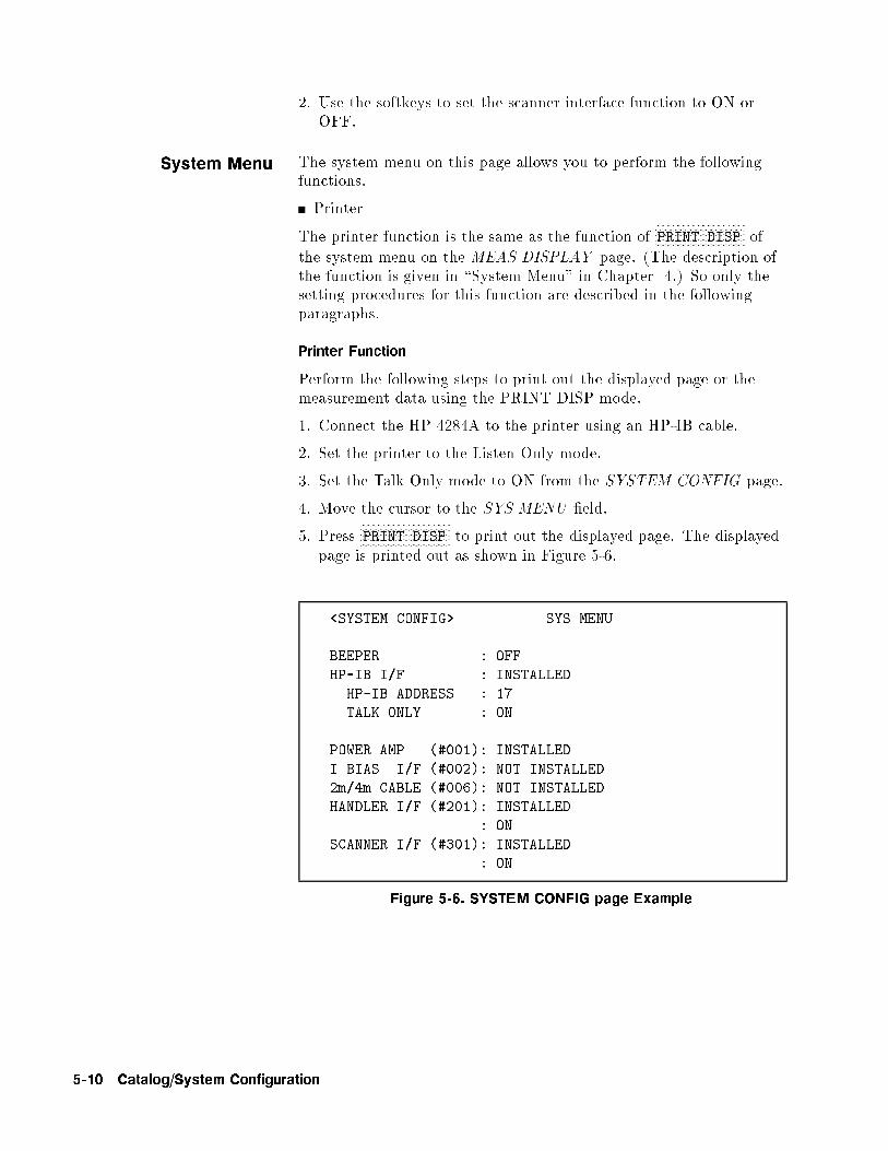
2. Use the softkeys to set the scanner interface function to ON orOFF.
System Menu The system menu on this page allows you to perform the followingfunctions.
Printer
The printer function is the same as the function ofNNNNNNNNNNNNNNNNNNNNNNNNNNNNNNNNPRINT DISP of
the system menu on the MEAS DISPLAY page. (The description ofthe function is given in \System Menu" in Chapter 4.) So only thesetting procedures for this function are described in the followingparagraphs.
Printer Function
Perform the following steps to print out the displayed page or themeasurement data using the PRINT DISP mode.
1. Connect the HP 4284A to the printer using an HP-IB cable.
2. Set the printer to the Listen Only mode.
3. Set the Talk Only mode to ON from the SYSTEM CONFIG page.
4. Move the cursor to the SYS MENU �eld.
5. PressNNNNNNNNNNNNNNNNNNNNNNNNNNNNNNNNPRINT DISP to print out the displayed page. The displayed
page is printed out as shown in Figure 5-6.
<SYSTEM CONFIG> SYS MENU
BEEPER : OFF
HP-IB I/F : INSTALLED
HP-IB ADDRESS : 17
TALK ONLY : ON
POWER AMP (#001): INSTALLED
I BIAS I/F (#002): NOT INSTALLED
2m/4m CABLE (#006): NOT INSTALLED
HANDLER I/F (#201): INSTALLED
: ON
SCANNER I/F (#301): INSTALLED
: ON
Figure 5-6. SYSTEM CONFIG page Example
5-10 Catalog/System Configuration

SELF TEST Page When you press �CATALOG/SYSTEM� andNNNNNNNNNNNNNNNNNNNNNNNNNNNNNSELF TEST , the SELF TEST
page will be displayed. This SELF TEST page is for service use.You can check the HP 4284A's digital functions using the self testfunctions listed on this page. The following self tests are includedin this page. (Each number in parenthesis is used when each test isselected.)
Memory Card Read/Write Test (No.1 )
LED Display Test (No.2 )
LCD Display Test (No.3 )
Handler Interface Test (No.4 )
Scanner Interface EEPROM Read/Write Test (No.5 )
Scanner Interface Input/Output Test (No.6 )
Bias Current Interface Input/Output Test (No.7 )
There are two �elds on this page, <SELF TEST>, and TEST
MENU .
Each test is described in the following paragraphs.
The available �elds and the softkeys which corresponded to the �eldon this page are shown in Figure 5-7 and Figure 5-8.
Catalog/System Configuration 5-11

Figure 5-7. Available Fields on the SELF TEST Page
Figure 5-8. Available Softkeys on the SELF TEST Page
5-12 Catalog/System Configuration

Memory Card R/W TestDescription
This test is used to check the read and write functions of the memorycard. When this test is started, a bit pattern is written to the loweraddress of the memory card, then pattern is read back and checked.This write pattern check is repeated from the low to high memoryaddresses.
How to Perform the Memory Card R/W Test
Perform the following steps to perform the memory card R/W test.
1. Move the cursor to the TEST MENU �eld on the SELF TEST
page.
2. Press �1� and �ENTER�, to select test number 1. The � MEMORY
CARD R/W TEST screen will be displayed, and the followinginformation indicating the address of the memory card isdisplayed.
START ADRS (HEX)= : Start address as a hexadecimalexpression
END ADRS (HEX)= : End address as a hexadecimalexpression
TEST ADRS (HEX)= : Current testing address as ahexadecimal expression
3. Insert a memory card into the MEMORY card slot on the frontpanel.
Note When this test is performed, data stored on the memory card isretained.
Caution While this test is in progress, DO NOT remove the memory card,and DO NOT turn the HP 4284A OFF. If you do the data stored onthe memory card may be lost.
4. PressNNNNNNNNNNNNNNNNNNNNNNNNNNNNNNNNTEST START to start the test.
Note To abort the test, pressNNNNNNNNNNNNNNNNNNNNNNNNNNTEST END .
If the test failed, the test is aborted and TEST ADRS (HEX)=onthe display shows the address at which the test failed. Retry thetest from step 1.
If the test passed, Test completed. will be displayed on thesystem message line.
5. PressNNNNNNNNNNNNNNNNNNNNNNNNNNTEST END to exit from the �MEMORY CARD R/W TEST
display.
Catalog/System Configuration 5-13

LED Display TestDescription
This test checks the �ve LEDs on the front panel. When this test isstarted, �ve LED indicators, RMT , LTN , TLK , SRQ and DC BIAS ,will be toggled ON and OFF once per second.
How to Perform the LED Display Test
Use the following steps to perform the LED display test.
1. Move the cursor to the TEST MENU �eld on the SELF TEST
page.
2. Press �2� and �ENTER� to select test number 2. The �LEDDISPLAY TEST screen will be displayed.
3. PressNNNNNNNNNNNNNNNNNNNNNNNNNNNNNNNNTEST START to start the test. The �ve LED indicators,
RMT , LTN , TLK , SRQ and DC BIAS , will be toggled ON andOFF once per second.
4. PressNNNNNNNNNNNNNNNNNNNNNNNNNNTEST END to stop the test and to exit from the �LED
DISPLAY TEST screen.
LCD Display TestDescription
This test checks the front panel LCD. When this test is started, allLCD characters used are displayed and toggled between the normaland inverse modes once per second.
How to Perform the LCD Display Test
Perform the following steps to perform the LCD display test.
1. Move the cursor to the TEST MENU �eld on the SELF TEST
page.
2. Press �3� and �ENTER�, to set the test number to 3. The �LCDDISPLAY TEST screen and all LCD characters will be displayed.
3. PressNNNNNNNNNNNNNNNNNNNNNNNNNNNNNNNNTEST START to start the test. The display will toggle
between the normal and inverse modes once per second.
4. PressNNNNNNNNNNNNNNNNNNNNNNNNNNTEST END to stop the test and to exit from the �LCD
DISPLAY TEST screen.
Handler I/F TestDescription
This test checks the output signals of the Option 201 or 202 HandlerInterface. When this test is started, each of the handler outputsignals is sequentially asserted for one second, until all output signals
have been asserted, then the sequence is repeated untilNNNNNNNNNNNNNNNNNNNNNNNNNNTEST END is
pressed. This test using the Handler Simulator (HP PN 04278-65001)is described on CHAPTER 10, PERFORMANCE TEST .
5-14 Catalog/System Configuration

Scanner I/F EEPROMR/W Test Description
This test checks the read and write functions of EEPROM for theOption 301 Scanner Interface. When this test is started, a bitpattern is written to the lower address of the EEPROM, then thewrite pattern is checked by reading back the bit pattern. This writepattern check is repeated from low to high EEPROM addresses.
How to Perform the Scanner I/F EEPROM R/W Test
Perform the following steps to perform the scanner interfaceEEPROM R/W test.
1. Move the cursor to the TEST MENU �eld on the SELF TEST
page.
2. Press �5� and �ENTER�, to set the test number to 5. The�SCANNER I/F EEPROM R/W TEST screen will be displayed,and the following messages indicating the address of the scannerinterface EEPROM are displayed.
START ADRS (HEX)= : Start address as a hexadecimalexpression
END ADRS (HEX)= : End address as a hexadecimalexpression
TEST ADRS (HEX)= : Current testing address as ahexadecimal expression
Note The Data stored in the EEPROM is retained when this test isperformed.
3. PressNNNNNNNNNNNNNNNNNNNNNNNNNNNNNNNNTEST START to start the test.
Note To abort the test, pressNNNNNNNNNNNNNNNNNNNNNNNNNNTEST END .
If the test failed, the test is aborted and TEST ADRS (HEX)= onthe display will show the address at which the test failed. Restartfrom step 1.
If the test passed, the message Test completed. will be displayedon the system message line.
4. PressNNNNNNNNNNNNNNNNNNNNNNNNNNTEST END to exit from the �SCANNER I/F EEPROM
R/W TEST screen.
Catalog/System Configuration 5-15

Scanner I/F I/O TestDescription
This test checks the input/output signals of the Option 301 ScannerInterface. When the test is started, two scanner output signals(/INDEX and /EOM) are asserted alternately, and the input signals(CH No. and /CH VALID) are read when only the status of these
signals is switched. These sequence is repeated untilNNNNNNNNNNNNNNNNNNNNNNNNNNTEST END is
pressed. This test uses the Scanner Simulator (HP PN 04278-65301)described on CHAPTER 10, PERFORMANCE TEST .
Bias Current I/F I/O TestDescription
This test checks the input/output signals of the Option 002 BiasCurrent Interface. When the test is started, the /CS 0 and /CS 1output signals are alternately asserted, and ADDRESS and DO0to DO7 output signals are changed in ascending order. Inputsignals DI0 to DI15 are read when only the status of these signals is
switched. This sequence is repeated untilNNNNNNNNNNNNNNNNNNNNNNNNNNTEST END is pressed. This
test uses the Bias Current Interface Simulator (HP PN 42841-65001)described on Chapter 10.
5-16 Catalog/System Configuration
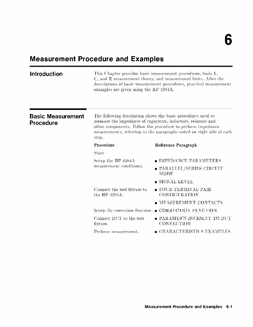
6
Measurement Procedure and Examples
Introduction This Chapter provides basic measurement procedures, basic L,C, and R measurement theory, and measurement hints. After thedescriptions of basic measurement procedures, practical measurementexamples are given using the HP 4284A.
Basic MeasurementProcedure
The following description shows the basic procedures used tomeasure the impedance of capacitors, inductors, resistors andother components. Follow the procedure to perform impedancemeasurements, referring to the paragraphs noted on right side of eachstep.
Procedure Reference Paragraph
Start
Setup the HP 4284Ameasurement conditions.
IMPEDANCE PARAMETERS
PARALLEL/SERIES CIRCUITMODE
SIGNAL LEVEL
Connect the test �xture tothe HP 4284A.
FOUR-TERMINAL PAIRCONFIGURATION
MEASUREMENT CONTACTS
Setup the correction function. CORRECTION FUNCTION
Connect DUT to the test�xture.
PARASITICS INCIDENT TO DUTCONNECTION
Perform measurement. CHARACTERISTICS EXAMPLES
Measurement Procedure and Examples 6-1

ImpedanceParameters
All circuit components, resistors, capacitors or inductors, haveparasitic components lurking in the shadows waiting for the unwary,for example unwanted resistance in capacitors, unwanted capacitancein inductors, and unwanted inductance in resistors. Thus simplecomponents should be modeled as complex impedances, for in factthat is what they are!
Figure 6-1 (A) shows the impedance de�nitions and (B) shows vectorrepresentation of impedance. Impedance, Z is the total oppositionthat a circuit or device o�ers to the ow of alternating current at agiven frequency. Z contains a real and an imaginary part, and it isexpressed in rectangular form as Resistance and Reactance, or inpolar form as magnitude of Impedance and Phase as follows.
Z = R + jX = jZj 6 �
jZj =pR2 +X2
� = arctan
�jXj
R
�
R = Rs
Where,
Z : Impedance [ ]R : Resistance [ ]X : Reactance [ ]jZj : Magnitude of Impedance [ ]� : Phase of Impedance [deg or rad]Rs : Series Resistance [ ]
6-2 Measurement Procedure and Examples

Figure 6-1. Definition of Impedance
The following parameters can be used to represent the reactance.
X = 2�fL
Where,
f : Frequency [Hz]L : Inductance [H]
In addition to these parameters, the Quality Factor (Q) andDissipation Factor (D) are used to describe the quality ofcomponents.
Q =1
D=jX j
R
Where,
Q : Quality FactorD : Dissipation Factor
In some case, the reciprocal of impedance (Admittance), Y isused. Figure 6-2 shows the vector representation of admittance. AsZ (Impedance), Y contains a real and an imaginary part, and isexpressed in rectangular form as Conductance and Susceptance, or inpolar form as magnitude of Admittance and Phase. The following areexpressions for Admittance.
Measurement Procedure and Examples 6-3

Y =1
ZY = G+ jB = jYj 6 �
jYj =pG2 +B2 =
1
jZj
� = arctan
�jBj
G
�= ��
B = 2�fC
Q =1
D=jBj
G
G =1
Rp
Where,
Y : Admittance [ S ]G : Conductance [ S ]B : Susceptance [ S ]jYj : Magnitude of Admittance [ S ]� : Phase of Admittance [deg or rad]C : Capacitance [ F ]Rp : Parallel Resistance [ ]
Note The jYj-� measurement function of the HP 4284A can obtain the jYjand � parameters given in the above equations.
Figure 6-2. Vector Representation of Admittance
6-4 Measurement Procedure and Examples
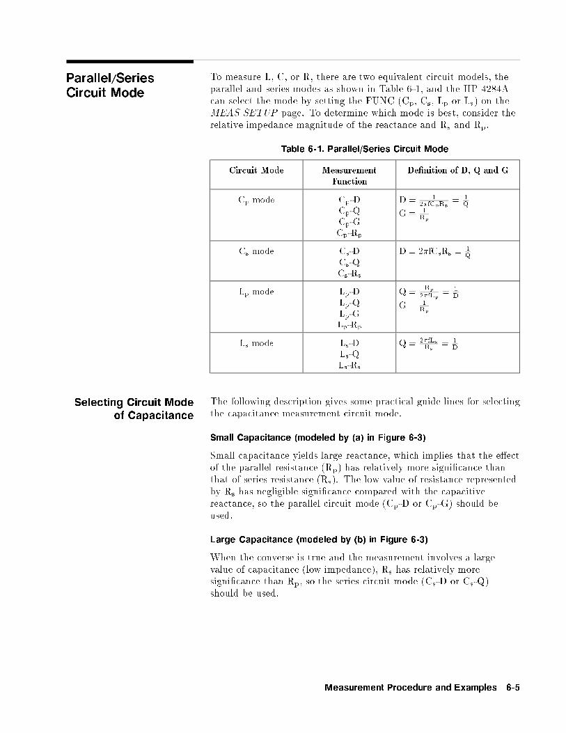
Parallel/SeriesCircuit Mode
To measure L, C, or R, there are two equivalent circuit models, theparallel and series modes as shown in Table 6-1, and the HP 4284Acan select the mode by setting the FUNC (Cp, Cs, Lp or Ls) on theMEAS SETUP page. To determine which mode is best, consider therelative impedance magnitude of the reactance and Rs and Rp.
Table 6-1. Parallel/Series Circuit Mode
Circuit Mode Measurement
Function
De�nition of D, Q and G
Cp mode Cp-DCp-QCp-GCp-Rp
D = 12�fCpRp
= 1Q
G = 1Rp
Cs mode Cs-DCs-QCs-Rs
D = 2�fCsRs =1Q
Lp mode Lp-DLp-QLp-GLp-Rp
Q =Rp
2�fLp= 1
D
G = 1Rp
Ls mode Ls-DLs-QLs-Rs
Q = 2�fLsRs
= 1D
Selecting Circuit Mode
of Capacitance
The following description gives some practical guide lines for selectingthe capacitance measurement circuit mode.
Small Capacitance (modeled by (a) in Figure 6-3)
Small capacitance yields large reactance, which implies that the e�ectof the parallel resistance (Rp) has relatively more signi�cance thanthat of series resistance (Rs). The low value of resistance representedby Rs has negligible signi�cance compared with the capacitivereactance, so the parallel circuit mode (Cp-D or Cp-G) should beused.
Large Capacitance (modeled by (b) in Figure 6-3)
When the converse is true and the measurement involves a largevalue of capacitance (low impedance), Rs has relatively moresigni�cance than Rp, so the series circuit mode (Cs-D or Cs-Q)should be used.
Measurement Procedure and Examples 6-5

Figure 6-3. Capacitance Circuit Mode Selection
The following is a rule of thumb for selecting the circuit modeaccording to the impedance of the capacitor.
�Above approx. 10 k : use parallel circuit mode�Below approx. 10 : use series circuit mode�Between above values : follow the manufacturer's
recommendation
For example, to measure a 20 �F capacitor at 1 kHz (impedance willbe approximately 8 ), the Cs-D or Cs-Q function is suitable.
Selecting Circuit Modeof Inductance
The following description gives some practical guide lines for selectingthe inductance measurement circuit mode.
Large Inductance (modeled by (a) in Figure 6-4)
The reactance at a given frequency is relatively large (comparedwith that of a small inductance), so the parallel resistance becomesmore signi�cant than the series component. So, a measurement inthe parallel equivalent circuit mode (Lp-D, Lp-Q or Lp-G) is moresuitable.
Small Inductance (modeled by (b) in Figure 6-4)
Conversely, for low values of inductance the reactance becomesrelatively small (compared with that of a large inductance) sothe series resistance component is more signi�cant. So, the seriesequivalent circuit mode (Ls-D or Ls-Q) is the appropriate choice.
6-6 Measurement Procedure and Examples

Figure 6-4. Inductance Circuit Mode Selection
The following is a rule of thumb for selecting the circuit modeaccording to the impedance of the inductor.
�Below approx. 10 : use series circuit mode�Above approx. 10 k : use parallel circuit mode�Between above values : follow the manufacturer's
recommendation
For example, to measure a 1 mH inductor at the 1 kHz (impedancemay be approximately 6.3 ), Ls-D or Ls-Q function is suitable.
Signal Level Most components have impedance characteristics that are dependenton the applied signal level. So, the oscillator level setting should beset appropriate for the DUT.
Signal LevelAcross The DUT
Figure 6-5 shows a simpli�ed model of the HP 4284A and a DUT.The signal level across the DUT depends on the oscillator level, thesource resistance of the HP 4284A, and the impedance of the DUT,as follows.
jVmj =jZxj
jRso + Zxj� jVoscj
jImj =jVoscj
jRso + Zxj
Where, jVoscj : oscillator voltage level of the HP 4284A,Rso : Source resister of the HP 4284A (= 100 ),jVmj : Signal voltage level applied on DUT,jImj : Signal current level owed in DUT,jZxj : Impedance of DUT.
Measurement Procedure and Examples 6-7

Figure 6-5. Simplified Model of Signal Level and DUT
Oscillator Level Setting The HP 4284A's oscillator level (Vosc in Figure 6-5) can be set to theappropriate value in the voltage or current mode. Using the ALC(automatic level control) function, the signal level set is the same asthe applied level across the DUT (Vm or Im in Figure 6-5). So thesignal level setting mode can be selected in the following four ways.
Oscillator level set as voltage and ALC set to OFF:The open terminal voltage is set to the entered voltage value inthe LEVEL �eld.
Oscillator level set as current and ALC set to OFF:The short terminal current is set to the entered current value inthe LEVEL �eld.
Oscillator level set as voltage and ALC set to ON:The signal level across the DUT is set to the entered voltagevalue in the LEVEL �eld.
Oscillator level set as current and ALC set to ON:The signal level across the DUT is set to the entered currentvalue in the LEVEL �eld.
For more information for the ALC function, refer to Chapter 4,Automatic Level Control Function.
Note By using the level monitor function (Vm and Im on the MEAS
DISPLAY page), the actual signal level across the DUT (Vm and Imin Figure 6-5) can be monitored.
Signal Level Setting Selection Example for Inductance Measurements
An inductor's inductance value may di�er widely depending on thecurrent through the inductor due to the permeability of its corematerial. Inductance measurements under constant current signallevels allows you to extract the frequency characteristics of theinductor isolated from its signal level characteristics.
6-8 Measurement Procedure and Examples

To make constant current level measurements, set appropriateoscillator level in current value, and set ALC to ON. The signalcurrent level through the inductor will be constant.
Four-Terminal PairConfiguration
Generally, any mutual inductance, interference of the measurementsignals, and unwanted residual factors in the connection methodincidental to ordinary termination methods will have signi�cante�ects on the measurements, especially at a high frequency. TheHP 4284A employs the four-terminal pair measurement con�gurationwhich permits easy, stable, and accurate measurements and avoidsthe measurement limitations inherent to such factors.
Figure 6-6 shows the four-terminal pair measurement principle. TheUNKNOWN terminals consists of four coaxial connectors.
HCUR : High currentHPOT : High potentialLPOT : Low potentialLCUR : Low current
Figure 6-6. Four-Terminal Pair Measurement Principle
The four-terminal pair measurement method has the advantagein both low and high impedance measurements. The outer shieldconductors work as the return path for the measurement signalcurrent (they are not grounded). The same current ows throughboth the center conductors and outer shield conductors (in oppositedirections), but no external magnetic �elds are generated aroundthe conductors (the magnetic �elds produced by the inner and outercurrents completely cancel each other). Because the measurementsignal current does not develop an inductive magnetic �eld, test leads
Measurement Procedure and Examples 6-9

do not contribute additional errors due to self or mutual inductancebetween the individual leads.
MeasurementContacts
This paragraph gives general notes and techniques for using thefour-terminal pair con�guration e�ciently. To realize accuratemeasurements using the four-terminal pair measurement technique,the following are required to make measurement contacts (thenumber labels in the following description corresponds to thenumbers in Figure 6-7).
1. The signal path between the HP 4284A and DUT should be asshort as possible.
2. To construct the four-terminal pair measurement circuitcon�guration, the outer shields of HCUR and HPOT, LCUR andLPOT terminals must be respectively connected together at thepoint as near as possible to the point at which the DUT willconnected.
3. Keep connections between the point at which the shielding endsand DUT as short as possible.
Figure 6-7. Measurement Contacts
The following paragraphs will give you some techniques for using thefour-terminal pair con�guration e�ectively and e�ciently.
6-10 Measurement Procedure and Examples

Capacitance To Ground To measure capacitors of 10 pF or less, the stray capacitance (whenthe conductors are grounded, this is capacitance to ground), betweenthe measurement contacts and the conductors near the capacitor willin uence the measurement, as shown in Figure 6-8.
Figure 6-8. Model of Capacitance to Ground
To minimize the stray capacitance of the test leads, the centerconductor of the test leads should be kept as short as possible, asshown in Figure 6-9 (A). If four-terminal pair connections are closeto the point where contact is made with the DUT, interconnect theshields of the measurement terminals to the conductor to reduce thein uence of the stray capacitance to ground, as shown in Figure 6-9(B).
Measurement Procedure and Examples 6-11

Figure 6-9. Reducing Capacitance to Ground
Contact Resistance Contact resistance between the contacting terminals and theDUT causes measurement error when measuring large values ofcapacitance, especially in D (dissipation factor) measurements.
When measuring large capacitance values, the four-terminalmeasurement contacts have the advantage of less measurement erroras compared to the two terminal method. Select a test �xture whichcan hold the DUT tight to stabilize the connection.
6-12 Measurement Procedure and Examples

Figure 6-10. Contact Resistance
Extending Test Leads When extending the four-terminal pair test leads to the contactsof DUT, make the contacts as shown in Figure 6-11. If themeasurement contact cannot be made using the four-terminal paircon�guration, use one of the connection methods shown in Figure6-12, to make the measurement contact.
Figure 6-11. Extending The Four-Terminal Pair Test Leads
Measurement Procedure and Examples 6-13

Figure 6-12. Measurement Contacts for Test Leads Extension
6-14 Measurement Procedure and Examples

Guarding For LowCapacitance
Measurements
Use a guard plate to minimize measurement errors caused by straycapacitance when measuring low capacitance values, such as lowcapacitance chip capacitors. Figure 6-13 shows an example ofmeasurement contacts using a guard plate in the four-terminal pairmeasurement con�guration.
Figure 6-13. Example DUT Guard Plate Connection
Shielding Shielding minimizes the e�ects of electrical noise picked up by thetest leads. So provide a shield plate and connect it to the outershield conductors of the four-terminal pair test leads as shown inFigure 6-14.
Figure 6-14. Guard Shield
Measurement Procedure and Examples 6-15

Correction Functions The HP 4284A has powerful correction functions, Cable Lengthcorrection, and OPEN, SHORT, and LOAD corrections. Thesecorrection functions are used to correct additional error due tothe test �xture and the test leads. Table 6-2 lists the Correctionfunctions with a brief description.
Table 6-2. Correction Functions
Correction
Selection
Description Typical Usage
Cable LengthCorrection
Correct phase shifterror due to the 1 or2 m test Leads.
� Measurements using theHP 16048A/D
OPENCorrection
Correct for strayadmittance due tothe test �xture.
� High impedance measurements
SHORT
CorrectionCorrect for residualimpedance due totest �xture.
� Low impedance measurements
OPEN/SHORT
Correction
Correct the stray
admittance and
residual impedancedue to the test�xture.
� Precise measurements
OPEN/SHORT/
LOAD
Correction
Correct any error
due to the test
�xture and test leads
by using the
standard.
�
�
Measurements to be referenced to
a standard
Measurements using a test �xture
that has complicated impedancecharacteristics
For example, the HP 4284Acombined with the scanner.
6-16 Measurement Procedure and Examples

Simple measurements using an HP supplied direct connecting test�xture
In this case, LOAD correction is not required, OPEN/SHORTcorrection is enough to correct the residual errors.
Measurements using HP test leads and a test �xture.
In this case, CABLE LENGTH and OPEN/SHORT correctionis used. Of course CABLE CORRECTION must be performedcompletely described in \Cable Length Selection" in Chapter 4.
Measurement Procedure and Examples 6-17

Precise measurements to be referenced to a working standard.
Use the working standard as the LOAD reference DUT andperform the OPEN/SHORT/LOAD correction.
Measurements using a test �xture that has complicated impedancecharacteristics.
In this case, use the OPEN/SHORT/LOAD correction. Whenyou combine a scanner, the HP 4284A with Option 301 scannerinterface provides powerful error correction functions for up tothree sets of OPEN/SHORT/LOAD correction data for 128channels.
6-18 Measurement Procedure and Examples

Performing OPENCorrection
To perform an OPEN correction data measurement, set up an OPENcondition, nothing is connected to the test �xture. When the OPENmeasurement is being performed, don't touch or move your handsnear the test �xture.
Performing SHORTCorrection
To perform a SHORT correction data measurement, set up a SHORTcondition, using a shorting bar to short between high terminal andlow terminal of the UNKNOWN terminals.
Figure 6-15 shows a sample shorting bar (HP Part Number5000-4226) for the HP 16047A/C/D test �xtures.
Figure 6-15. Sample Shorting Plate
The shorting bar should have very low residual impedance, so a highconductivity metal plate that is not easily corroded, is recommendedfor the shorting plate. (It must be clean.)
Measurement Procedure and Examples 6-19

Photo
Figure 6-16. Shorting Plate Connection
Performing LOADCorrection
To perform LOAD correction data measurement, connect the LOADstandard to the measurement contacts.
Preparing the Standard
It is necessary to prepare the working standard, such as a standardresistor and standard capacitor. It is recommended that you selecta standard whose impedance is as close as possible to DUT'simpedance. The following are recommendations for selectingstandards.
For capacitance measurements:
A standard capacitor whose capacitance is nearly equal to theDUT capacitance is recommended.
For resistance measurements:
A standard resistor whose resistance is nearly equal to DUT'sresistance is recommended.
For inductance measurements:
A standard inductor whose inductance is nearly equal to DUT'sinductance is recommended.
Reference Values of the LOAD Standard
Enter speci�ed reference values of the standard as the REF A andREF B values using the appropreate function on the CORRECTIONpage. For example, When using a standard capacitor which hasa speci�ed parallel capacitance and D values, enter the speci�ed
6-20 Measurement Procedure and Examples

parallel capacitance value as the REF A value and the speci�ed Dvalue as the REF B value with Cp-D function.
Note If the REF A and REF B values are entered with the Cp-D function,measurements with other functions (such as the jZj-� function) canbe performed.
Using the Pre-Measured Device for the LOAD
Even if you have no standard which has speci�ed reference values,you can perform a LOAD correction using a device such as a generalpurpose capacitor or resistor. The pre-measured values of a deviceare used for the REF A and REF B values. Follow the procedureshown in below to use a device for the LOAD standard.
1. Prepare a device, whose impedance is as close as possible to theDUT's impedance, for the LOAD standard.
2. If the device has BNC connectors constructed in the four-terminalpair con�guration, measure the device directly, do not use a test�xture (connect it directly to the HP 4284A).
Measurement Procedure and Examples 6-21

If the device does not have four-terminal pair measurementterminals, measure the device using a direct coupling test �xture(such as the HP 16047A/C/D).
3. On the CORRECTION page, enter the measured values obtainedin step 2 as the REF A and REF B values with the function usedin step 2.
Parasitics Incidentto DUT Connection
You should consider that some parasitics remain in measurementpath even after performing corrections, as follows.
Figure 6-16 shows parasitic impedance model after correctionsperformed using the HP 16047A/C/D test �xture. In this case, tominimize the in uence of parasitics on measurement the values, insertDUT completely into the test �xture (keep the leads of the DUT asshort as possible).
Figure 6-17. Parasitic Impedance Model (Using the HP 16047A/C/D)
Lo: Residual inductance in DUT leadRo: Lead resistance in DUT leadCo: Stray capacitance
6-22 Measurement Procedure and Examples

CharacteristicsExample
Figure 6-18 shows typical characteristics of various components. Ascan be seen in the �gure, a component may have di�erent e�ectiveparameter values dependent upon its operating conditions. Themeasured values most useful in actual applications are obtained fromprecise measurement under the actual operating conditions.
Figure 6-18. Typical Characteristics of Components
Measurement Procedure and Examples 6-23

CapacitorMeasurements
This paragraph describes practical example of measuring a 470 pFceramic capacitor.
The basic procedure ow to perform this measurement is the same asthe BASIC MEASUREMENT PROCEDURE described previously.In this example a 470 pF ceramic capacitor will be measured underthe following conditions.
Sample (DUT) : 470 pF ceramic capacitor (HP Part Number0160-3335)
MeasurementConditions
Function : Cp-DFrequency : 1 MHzTest Signal Level : 1.5 V
Do not apply DC voltage
or current to the UNKNOWN
terminals. Doing so will
damage the HP 4284A. Before
you measure a capacitor, besure the capacitor is fullydischarged.
1. Turn the HP 4284A ON.
2. Setup the HP 4284A's measurement conditions by �lling in the�elds on the MEAS DISPLAY page.
Set FREQ �eld to 1 MHz, and LEVEL �eld to 1.5 V. (The otherfunctions, including the measurement function are left as thedefault settings.)
a. Move the cursor to the FREQ �eld. The current measurementfrequency, 1.00000kHz, is displayed in this �eld.
b. Press �1�. 1 will be displayed on the system message line, and
the softkey labels will change to the available units (NNNNNNNNHz ,
NNNNNNNNNNNkHz ,
andNNNNNNNNNNNMHz ). Press
NNNNNNNNNNNMHz . 1.00000MHz is now displayed in the
FREQ �eld.
Note The FREQUENCY can be changed usingNNNNNNNNNNNNNNINCR and
NNNNNNNNNNNNNNDECR displayed
when the CURSOR moved to the FREQ �eld.
c. Move the cursor to the LEVEL �eld. The current test signallevel, 1.00V, is displayed in this �eld.
d. Press �1�, �.�, �5�. 1.5 will be displayed on the system messageline, and the softkey labels are changed to the available units
(NNNNNNNNmV ,
NNNNNV ,
NNNNNNNN�A ,
NNNNNNNNmA and
NNNNNA ). Press
NNNNNV . 1.50V is now displayed in
the LEVEL �eld.
Note The OSC LEVEL can be changed using withNNNNNNNNNNNNNNINCR and
NNNNNNNNNNNNNNDECR
displayed when the cursor is moved to the LEVEL �eld.
Note These measurement conditions can also be set from the MEAS
SETUP page which is displayed when �MEAS SETUP� is pressed. Theset up operation from the MEAS SETUP page is the same as in thepreceding steps 1 to 4.
6-24 Measurement Procedure and Examples

3. Connect the test �xture to the HP 4284A.
The HP 16047A Direct Couple Test Fixture (general purpose) isused for this measurement.
Connect the HP 16047A to the HP 4284A's UNKNOWNterminals, as shown in Figure 6-19.
Figure CONNECT-FIXTURE here.
Figure 6-19. Connecting the HP 16047A
4. Perform the correction.
To compensate for the HP 16047A's residuals and strays, anOPEN/SHORT correction is required.
a. Leave the HP 16047A in an OPEN condition as shown inFigure 6-17.
b. Press �MEAS SETUP�, andNNNNNNNNNNNNNNNNNNNNNNNNNNNNNNNNCORRECTION . The CORRECTION
page will now be displayed.
c. Move the cursor to the OPEN �eld.NNNNNNNNON ,
NNNNNNNNNNNOFF and
NNNNNNNNNNNNNNNNNNNNNNNNNNNNNMEAS OPEN
will be displayed.
d. PressNNNNNNNNNNNNNNNNNNNNNNNNNNNNNMEAS OPEN to perform the OPEN correction data
measurement. Wait until the message OPEN measurement
completed. is displayed on the system message line.
e. PressNNNNNNNNON to set the OPEN correction function to ON.
f. Connect a shorting bar to the HP 16047A to set up theSHORT condition as shown in Figure 6-20.
Measurement Procedure and Examples 6-25

Figure SHORT-BAR here.
Figure 6-20. Connecting A Shorting Bar
g. Move the cursor to the SHORT �eld.NNNNNNNNON ,
NNNNNNNNNNNOFF and
NNNNNNNNNNNNNNNNNNNNNNNNNNNNNNNNMEAS SHORT will be displayed.
h. PressNNNNNNNNNNNNNNNNNNNNNNNNNNNNNNNNMEAS SHORT to perform the SHORT correction data
measurement. Wait until the message SHORT measurement
completed. is displayed on the system message line.
i. PressNNNNNNNNON to set the SHORT correction function to ON.
5. Connect DUT to the test �xture.
Insert the DUT into the HP 16047A's measurement contactsdeeply as shown in Figure 6-21.
Figure DUT here.
Figure 6-21. Connecting DUT
6. Perform the measurement.
6-26 Measurement Procedure and Examples

Press �DISPLAY FORMAT�.
Measurements are performed continuously by the internal trigger,and the capacitors measured Cp and D values are displayed aslarge characters as shown in Figure 6-22.
Figure 6-22. Measurement Results of A 470 pF Capacitor
InductanceMeasurements
This paragraph describes a practical example of measuring a 64 �Hmagnetic-core inductor.
The basic procedure ow to perform this measurement is the sameas for the BASIC MEASUREMENT PROCEDURE describedpreviously. A 64 �H magnetic-core inductor will be measured underthe following conditions.
Sample (DUT) : 64 �H magnetic-core inductor(HP Part Number 9140-1401)
MeasurementConditions
Function : Ls-Rs
Frequency : 100 kHzTest Signal Level : 10 mA (constant)
1. Turn the HP 4284A ON.
2. Setup the HP 4284A measurement conditions by �lling the �eldson the MEAS DISPLAY page.
Set FUNC to Ls-Rs, FREQ to 100 kHz, and LEVEL to 10 mAconstant. (The other functions will be left as the default settings.)
Measurement Procedure and Examples 6-27
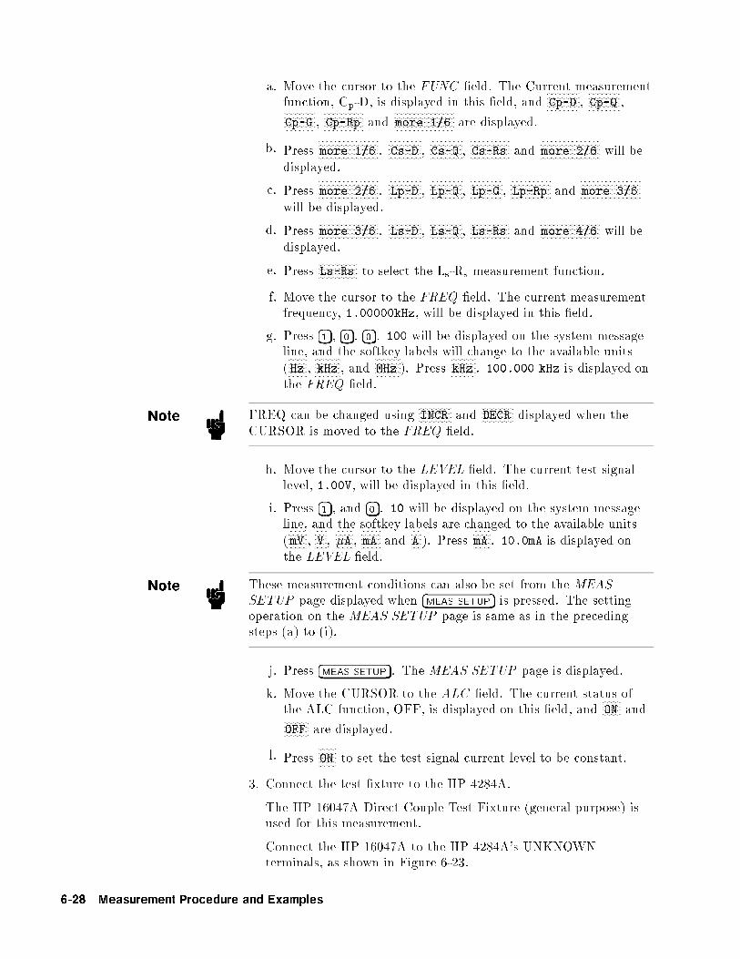
a. Move the cursor to the FUNC �eld. The Current measurementfunction, Cp-D, is displayed in this �eld, and
NNNNNNNNNNNNNNCp-D ,
NNNNNNNNNNNNNNCp-Q ,
NNNNNNNNNNNNNNCp-G ,
NNNNNNNNNNNNNNNNNCp-Rp and
NNNNNNNNNNNNNNNNNNNNNNNNNNmore 1/6 are displayed.
b. PressNNNNNNNNNNNNNNNNNNNNNNNNNNmore 1/6 .
NNNNNNNNNNNNNNCs-D ,
NNNNNNNNNNNNNNCs-Q ,
NNNNNNNNNNNNNNNNNCs-Rs and
NNNNNNNNNNNNNNNNNNNNNNNNNNmore 2/6 will be
displayed.
c. PressNNNNNNNNNNNNNNNNNNNNNNNNNNmore 2/6 .
NNNNNNNNNNNNNNLp-D ,
NNNNNNNNNNNNNNLp-Q ,
NNNNNNNNNNNNNNLp-G ,
NNNNNNNNNNNNNNNNNLp-Rp and
NNNNNNNNNNNNNNNNNNNNNNNNNNmore 3/6
will be displayed.
d. PressNNNNNNNNNNNNNNNNNNNNNNNNNNmore 3/6 .
NNNNNNNNNNNNNNLs-D ,
NNNNNNNNNNNNNNLs-Q ,
NNNNNNNNNNNNNNNNNLs-Rs and
NNNNNNNNNNNNNNNNNNNNNNNNNNmore 4/6 will be
displayed.
e. PressNNNNNNNNNNNNNNNNNLs-Rs to select the Ls-Rs measurement function.
f. Move the cursor to the FREQ �eld. The current measurementfrequency, 1.00000kHz, will be displayed in this �eld.
g. Press �1�, �0�, �0�. 100 will be displayed on the system messageline, and the softkey labels will change to the available units
(NNNNNNNNHz ,
NNNNNNNNNNNkHz , and
NNNNNNNNNNNMHz ). Press
NNNNNNNNNNNkHz . 100.000 kHz is displayed on
the FREQ �eld.
Note FREQ can be changed usingNNNNNNNNNNNNNNINCR and
NNNNNNNNNNNNNNDECR displayed when the
CURSOR is moved to the FREQ �eld.
h. Move the cursor to the LEVEL �eld. The current test signallevel, 1.00V, will be displayed in this �eld.
i. Press �1�, and �0�. 10 will be displayed on the system messageline, and the softkey labels are changed to the available units
(NNNNNNNNmV ,
NNNNNV ,
NNNNNNNN�A ,
NNNNNNNNmA and
NNNNNA ). Press
NNNNNNNNmA . 10.0mA is displayed on
the LEVEL �eld.
Note These measurement conditions can also be set from the MEAS
SETUP page displayed when �MEAS SETUP� is pressed. The settingoperation on the MEAS SETUP page is same as in the precedingsteps (a) to (i).
j. Press �MEAS SETUP�. The MEAS SETUP page is displayed.
k. Move the CURSOR to the ALC �eld. The current status ofthe ALC function, OFF, is displayed on this �eld, and
NNNNNNNNON and
NNNNNNNNNNNOFF are displayed.
l. PressNNNNNNNNON to set the test signal current level to be constant.
3. Connect the test �xture to the HP 4284A.
The HP 16047A Direct Couple Test Fixture (general purpose) isused for this measurement.
Connect the HP 16047A to the HP 4284A's UNKNOWNterminals, as shown in Figure 6-23.
6-28 Measurement Procedure and Examples

Figure CONNECT-FIXTURE-L here.
Figure 6-23. Connecting the HP 16047A
4. Perform the correction.
To compensate the HP 16047A's residuals and strays, anOPEN/SHORT correction is required.
a. Leave the HP 16047A in an OPEN condition as shown inFigure 6-21.
b. Press �MEAS SETUP�, andNNNNNNNNNNNNNNNNNNNNNNNNNNNNNNNNCORRECTION . The CORRECTION
page will be displayed.
c. Move the cursor to the OPEN �eld.NNNNNNNNON ,
NNNNNNNNNNNOFF and
NNNNNNNNNNNNNNNNNNNNNNNNNNNNNMEAS OPEN
will be displayed.
d. PressNNNNNNNNNNNNNNNNNNNNNNNNNNNNNMEAS OPEN to perform the OPEN correction data
measurement. Wait until the message OPEN measurement
completed. is displayed on the system message line.
e. PressNNNNNNNNON to set the OPEN correction function to ON.
f. Connect a shorting bar to the HP 16047A to set up theSHORT condition as shown in Figure 6-24.
Measurement Procedure and Examples 6-29

Figure SHORT-BAR-L here.
Figure 6-24. Connecting A Shorting Bar
g. Move the cursor to the SHORT �eld.NNNNNNNNON ,
NNNNNNNNNNNOFF and
NNNNNNNNNNNNNNNNNNNNNNNNNNNNNNNNMEAS SHORT will be displayed.
h. PressNNNNNNNNNNNNNNNNNNNNNNNNNNNNNNNNMEAS SHORT to perform the SHORT correction data
measurement. Wait until the message SHORT measurement
completed. is displayed on the system message line.
i. PressNNNNNNNNON to set the SHORT correction function to ON.
5. Connect the DUT to the test �xture.
Insert the DUT into the HP 16047A's measurement contactsdeeply, as shown in Figure 6-25.
Figure DUT-L here.
Figure 6-25. Connecting DUT
6. Perform the measurement.
6-30 Measurement Procedure and Examples

Press �DISPLAY FORMAT�.
Measurements are performed continuously by the internal trigger,and the measured Ls and Rs values of the magnetic-cored inductorare displayed in large characters as shown in Figure 6-26.
Figure 6-26. Measurement Results of The Magnetic-Cored Inductor
Measurement Procedure and Examples 6-31

If the HP 4284Adoes NOT MeasureCorrectly
The HP 4284A is working correctly but its measurement results seemstrange. For example:
The HP 4284A does not measure at all.
Measurement value is strange.
Measurement value is strange at a speci�c frequency point orpoints.
These situations may be caused by the incorrect correction data. Ifyou come upon these situations, use the following procedure to checkthe instrument.
1. Turn correction OFF.
a. Press �MEAS SETUP�,NNNNNNNNNNNNNNNNNNNNNNNNNNNNNNNNCORRECTION .
b. Move the cursor to the OPEN �eld and pressNNNNNNNNNNNOFF .
c. Move the cursor to the SHORT �eld and pressNNNNNNNNNNNOFF .
d. Move the cursor to the LOAD �eld and pressNNNNNNNNNNNOFF .
e. Press �DISPLAY FORMAT� and con�rm CORR: turns OFF.
2. Measure the DUT again. If the HP 4284A now measures properlythen the correction data may have been improperly obtained orsaved. Carefully perform the correction procedure again andmeasure the DUT.
For more information on the correction procedure, refer to chapter 4,\CORRECTION Page".
6-32 Measurement Procedure and Examples

7
Remote Control
Introduction This chapter provides the following information to remotely controlthe HP 4284A via the Hewlett-Packard Interface Bus (hp-ib).
Reference information for programming the HP 4284AIntroduction to the Standard Commands for ProgrammableInstruments (scpi)Tutorial information for the SCPI programmer
Hewlett-PackardInterface Bus(HP-IB)
HP-IB is Hewlett-Packard's implementation of IEEE standard488.1-1987. And IEEE standard 488.1-1987 is identical to theoriginal IEEE standard 488-1978.
HP-IB Connection When con�guring an HP-IB system, the following restrictions mustbe adhered to.
The total length of cable in one bus system must be less than orequal to two meters times the number of devices connected onthe bus (the HP-IB controller counts as one device) and the totallength of cable must not exceed 20 meters.
A maximum of 15 devices can be connected on one bus system.
There are no restrictions on how the cables are connected together.However, it is recommended that no more than four piggybackconnectors be stacked together on any one device. The resultingstructure could exert enough force on the connector mounting todamage it.
For example, a system containing six devices can be connectedtogether with cables that have a total length of less than or equal to12 meters (six devices � 2m/device = 12 meters). The individuallength of cable may be distributed in any manner desired as long asthe total length does not exceed the allowed maximum. If more thanten devices are to be connected together, cables shorter than twometers must be used between some of the devices to keep the totalcable length less than 20 meters.
Figure 7-1 shows an HP-IB interface connector. The HP 4284A usesall of the available HP-IB lines; therefore, damage to any connectorpin will adversely a�ect its HP-IB operation.
Remote Control 7-1

Figure 7-1. HP-IB Connector Signal/Pin Configuration
Table 7-1. HP-IB Interconnect Cables
HP Part Number Length
10833A 1 m (3.3 ft)
10833B 2 m (6.6 ft)
10833C 4 m (13.2 ft)
10833D 0.5 m (1.6 ft)
7-2 Remote Control

Typical HP-IB system interconnection is shown in Figure 7-2. TheHP-IB connector is �rmly fastened using two bolts to keep it fromworking loose during use.
Figure 7-2. Typical HP-IB System Interconnection
HP-IB Capability Table 7-2 lists the HP 4284A's HP-IB capabilities and functions.These functions provide the means for an instrument to receive,process, and transmit, commands, data, and status over the HP-IBbus.
Table 7-2. HP-IB Interface Capability
Code Function
SH1 Complete Source Handshake capability
AH1 Complete Acceptor Handshake capability
T5 Basic Talker; serial poll; unaddressed if MLA; Talk-Only
L4 Basic Listener; unaddressed if MTA; no Listen Only
SR1 Service Request capability
RL1 Remote/Local capability
DC1 Device Clear capability
DT1 Device Trigger capability
C0 No Controller capability
E1 Drivers are open-collector
Remote Control 7-3

HP-IB Addressing The HP 4284A's HP-IB address is stored in non-volatile memory andcan be set to any address from 0 to 30 by front panel key entry in theSYSTEM CONFIG page. When the HP 4284A is shipped from thefactory the default HP-IB address is 17. For more information, referto \How to Set the HP-IB Address" in Chapter 5.
HP-IB Bus Capability The HP 4284A will respond to the following bus commands whichare given as HP 9000 series 200/300 BASIC statements.
ABORT I/O (IFC)
ABORT I/O (IFC control line TRUE) halts all bus activity anddeselects the HP 4284A.
For example:
ABORT 7
CLEAR LOCKOUT/SET LOCAL
CLEAR LOCKOUT/SET LOCAL (REN control line false) releasesdevices on the bus from the lockout mode and returns themto local (front panel) control. The di�erence between CLEARLOCKOUT/SET LOCAL, and LOCAL is in the addressing methodused.
For example:
LOCAL 7
DEVICE CLEAR (SDC or DCL)
This command can be used with an address to clear a particulardevice (SDC : selected device clear) or used without an address (DCL: clears all devices). The HP 4284A will initialize the following itemsonly when it receives this command. Then the:
Input bu�er is clearedOutput data bu�er is clearedBit 4 (MAV bit) of the status byte is set to \0"
For example:
CLEAR 7
LOCAL (GTL)
LOCAL returns control of a listening device to front panel control.
For example:
LOCAL 717
7-4 Remote Control

LOCAL LOCKOUT (LLO)
LOCAL LOCKOUT disables the LOCAL operation (HP 4284A :Pressing �LCL�) of all devices on the bus. After this command is sentyou will be unable to operate the HP 4284A from the front panel.Execute the LOCAL command to undo LOCAL LOCKOUT.
For example:
LOCAL LOCKOUT 7
REMOTE
REMOTE sets the HP 4284A to the remote mode. When thiscommand is sent, front panel with the exception of �LCL� will bedisabled.
For example:
REMOTE 717
SPOLL
SPOLL is the serial polling command. SPOLL is used to place thestatus byte of the addressed instrument on the bus. The eight bitsof the status byte can be masked o� and read to determine theHP 4284A's operating state.
For example:
Var=SPOLL(717)
SERVICE REQUEST
The HP 4284A can send an SRQ (Service Request) control signalwhen it requires the controller to perform a task. An SRQ canbe thought of as an interrupt which informs the controller thatinformation is ready to be transmitted, or that an error conditionexists in the instrument. When the HP 4284A sends an SRQ it alsosets Bit 6 of the status byte. Bit 6 is the RQS (Request Service) bit,sometimes referred to as the status bit in connection with polling.When the HP 4284A is serially polled, it clears the RQS bit and theSRQ line, one of the �ve management control lines of the systeminterface. Any bit in the status byte can initiate an SRQ. The statusbyte may be masked by the user to determine which bits caused theHP 4284A to set the SRQ line. For more information on the statusbyte, refer to \Status Byte".
TRIGGER (GET)
Enables the HP 4284A to the TRIGGER bus command. Thiscommand may be sent to a selected device or to all devices addressedas listeners on the HP-IB bus. The HP 4284A must �rst beaddressed as a listener, second the trigger mode is set to the BUStrigger mode before the trigger message is sent.
For example:
Remote Control 7-5

SEND 7;UNL MTA LISTEN 17
TRIGGER 7
StandardCommands forProgrammableInstruments(SCPI)
Standard Commands for Programmable Instrument(scpi) is thenew universal command set adopted by Hewlett-Packard for testand measurement instrumentation by extending IEEE 488.2-1987.(SCPI is equal to TMSL, Test and Measurement Systems Language,which developed by Hewlett-Packard.) This language uses standardHP-IB hardware and will be used in many future Hewlett-PackardProducts. SCPI uses easy to learn, self explanatory commands, andis exible for both beginners and expert programmers. Detailed SCPIcommand descriptions are given in Chapter 8.
Figure 7-3. Functional Layers Diagram
7-6 Remote Control

Data Transfer The HP 4284A o�ers two data formats for HP-IB data transfer to thecontroller, ASCII and BINARY. The data transfer rates for thesedata formats are di�erent.
ASCII Format The ASCII data format is the default output format. When theFORMat:DATA ASCII command is executed, the HP 4284A transfersdata in the ASCII format. The ASCII data output format on theMEAS DISPLAY, BIN No. DISPLAY, or BIN COUNT DISPLAY
page is described in Figure 7-4.
Figure 7-4. ASCII Format 1
The <DATA A>, <DATA B>, <STATUS>, and <BIN No.>formats are as follows.
<DATA A> and <DATA B> format:
The data output formats for <DATA A> (primary parameter'smeasurement data), and <DATA B> (secondary parameter'smeasurement data) uses the 12 ASCII character �xed lengthformat as follows.
SN.NNNNNESNN(S: +/�, N: 0 to 9, E: Exponent Sign)
<STATUS> Format:
The <STATUS> data shows the measurement status when gettingthe measurement data as follows.
Remote Control 7-7

Status Description
�1 No data (in the data bu�er memory)
0 Normal measurement data.
+1 Analog bridge is unbalanced.
+2 A/D converter is not working.
+3 Signal source overloaded.
+4 ALC unable to regulate.
The data output formats for <STATUS> uses the 2 ASCIIcharacter �xed length format as follows.
SN (S: +/�, N: 0 to 4)
Note When the <STATUS> is �1, 1, or 2, the measurement data is9.9E37. When the <STATUS> is 0, 3, or 4, the actual measurementdata is output.
<BIN No.> Format:
The <BIN No.> data shows the bin sorting results as follows.
Data Sorting Results
0 OUT OF BINS
+1 BIN 1
+2 BIN 2
+3 BIN 3
+4 BIN 4
+5 BIN 5
+6 BIN 6
+7 BIN 7
+8 BIN 8
+9 BIN 9
+10 AUX BIN
The <BIN No.> data is output with the measurement data onlywhen the comparator function is set to ON.
The data output formats for <BIN No.> uses a 2 or 3 ASCIIcharacter data length format as follows.
SN or SNN (S: +/�, N: 0 to 9)
The ASCII data output format on the LIST SWEEP DISPLAY
page is described in Figure 7-5. The data loop is repeated for thenumber of the sweep points.
7-8 Remote Control

Figure 7-5. ASCII Format 2 (List Sweep)
The <DATA A>, <DATA B>, <STATUS> formats are the sameas the formats on the MEAS DISPLAY, BIN No. DISPLAY, orBIN COUNT DISPLAY page. So the only the <IN/OUT> formatwill be described.
<IN/OUT> format:
The <IN/OUT> data shows the result of the list sweep'scomparator function.
Data Result
�1 LOW
0 IN
+1 HIGH
When the comparator function of the list sweep measurement isn'tused, the <IN/OUT> data output result is 0 (zero).
The data output formats for <IN/OUT> use the 2 ASCIIcharacter �xed length format as follows.
SN (S: +/�, N: 0 to 1)
Binary Format When the FORMat:DATA REAL,64 command is executed theHP 4284A transfers data in the BINARY format. The BINARYformat is the 64-bit oating point binary format speci�ed in IEEEStandard 754-1985. This is the same data format used by the HPTechnical computers, such as the HP 9000 series 200/300 computers.The BINARY data output format on the MEAS DISPLAY, BIN No.DISPLAY, or BIN COUNT DISPLAY page is shown in Figure 7-6.
Remote Control 7-9

Figure 7-6. BINARY Format 1
This data �eld is initiated by a unique code, the number sign (#). Asecond byte, (2), designates the number of the bytes for the \No.of the bytes transfer". \No. of the bytes transfer" designates thedata byte length. The last byte is zero (0), and has no meaning. Theresponse message terminator is, the EOI line is asserted while theNew Line (Line Feed) character (10 decimal) is being sent on the bus.
Floating Point Format Each data format of the <DATA A>, <DATA B>, <STATUS>, and<BIN No.> are common formats (8 bytes, IEEE 754 oating pointformat) as follows. The meaning of each data is the same as themeaning of each data in the ASCII format.
IEEE 754 Floating Point Format
Bit No. 7 6 5 4 3 2 1 0
First byte sent S Emsb E E E E E E
Second byte sent E E E Elsb Fmsb F F F
Third { seventh F F F F F F F F
byte sent...
......
......
......
...
Last byte sent F F F F F F F Flsb
Where,
Emsb : is the most signi�cant bit of the exponent.Elsb : is the least signi�cant bit of the exponent.Fmsb : is the most signi�cant bit of the fractional part.Flsb : is the least signi�cant bit of the fractional part.S : is the sign bit.E : is an exponent bit.F : is a fraction bit.
The real number RN represented in oating point format areprovided using the following formula. (EXP: Exponent part ofnumber, f: Fractional part of number)
When 0 < e < 11111111111 (2047)
7-10 Remote Control

RN = (�1)S � 2(EXP-1023) � (1 + f/252)
When e = 0
RN = (�1)S � 2-1022 � (f/252)
When e = 0, f = 0,
RN = 0
For example,
S = 1
EXP = 01111111111 (1023 decimal)
f = 1000 00000000 00000000 00000000 00000000 00000000 00000000 (251)
RN = (�1)1 � 2(1023�1023) �
�1 +
251
252
�
= �1� 1� 1:5
= �1:5
When the list sweep measurement is performed, the binary dataformat is as follows. <DATA A>, <DATA B>, <STATUS>, and<IN/OUT> are repeated as many times as there are sweep points.Each data format is the same as the 8-byte data format described inthe \Floating Point Format". The meaning of each data is the sameas each data in the ASCII format.
Figure 7-7. Binary Data Format For List Sweep Measurement
Remote Control 7-11

Trigger System Figure 7-8 shows the HP 4284A trigger state diagram when inREMOTE.
Figure 7-8. Trigger State Diagram
Each HP-IB trigger state is described in the following paragraphs.
IDLE state
During the IDLE state, the measurement data can be read by acontroller via HP-IB using the FETCh? query. To change the IDLEstate to the WAIT FOR TRIGGER state, the INITiate subsystemcommand must be used as shown in Figure 7-9.
Figure 7-9. INITiate Subsystem Commands and Trigger System
There are the following two conditions for the INITiate subsystemcommands.
1. INITiate:CONTinuous OFF condition
7-12 Remote Control

In this condition, the INITiate:IMMediate command must besent via HP-IB to change the IDLE state to the WAIT FORTRIGGER state after reading the measurement data by acontroller.
2. INITiate:CONTinuous ON condition
In this condition, the IDLE state is automatically changedto the WAIT FOR TRIGGER state without using theINITiate:IMMediate command after reading the measurementdata by a controller.
Note When the ABORt command is sent under any state, the HP 4284Astate is forced to the IDLE state. In this condition there are no datastored in the HP 4284A. If the FETCh? query is sent in this case, anerror (error message �230: "Data corrupt or stale") will occur.
WAITING FOR TRIGGER state
In this state, the HP 4284A can accept a trigger commandwhile in the remote condition. When the trigger command issent to the HP 4284A, the state is automatically changed to theMEASUREMENT state.
There are three kinds of the trigger commands: *TRG commoncommand, Group Execution Trigger (get) bus command, andTRIGger:IMMediate SCPI command. These commands are dividedinto two types in this trigger system. (Refer to Figure 7-10.)
Figure 7-10. Trigger System and Trigger Commands
1. TRIGger:IMMediate SCPI command
Either the WAIT FOR TRIGGER state or the IDLE state,the HP 4284A is triggered by sending the TRIGger:IMMediate
Remote Control 7-13
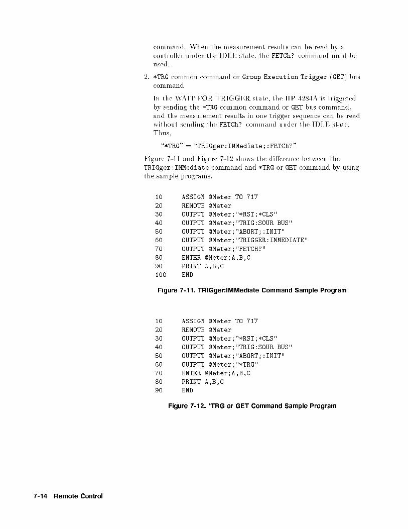
command. When the measurement results can be read by acontroller under the IDLE state, the FETCh? command must beused.
2. *TRG common command or Group Execution Trigger (GET) buscommand
In the WAIT FOR TRIGGER state, the HP 4284A is triggeredby sending the *TRG common command or GET bus command,and the measurement results in one trigger sequence can be readwithout sending the FETCh? command under the IDLE state.Thus,
\*TRG" = \TRIGger:IMMediate;:FETCh?"
Figure 7-11 and Figure 7-12 shows the di�erence between theTRIGger:IMMediate command and *TRG or GET command by usingthe sample programs.
10 ASSIGN @Meter TO 717
20 REMOTE @Meter
30 OUTPUT @Meter;"*RST;*CLS"
40 OUTPUT @Meter;"TRIG:SOUR BUS"
50 OUTPUT @Meter;"ABORT;:INIT"
60 OUTPUT @Meter;"TRIGGER:IMMEDIATE"
70 OUTPUT @Meter;"FETCH?"
80 ENTER @Meter;A,B,C
90 PRINT A,B,C
100 END
Figure 7-11. TRIGger:IMMediate Command Sample Program
10 ASSIGN @Meter TO 717
20 REMOTE @Meter
30 OUTPUT @Meter;"*RST;*CLS"
40 OUTPUT @Meter;"TRIG:SOUR BUS"
50 OUTPUT @Meter;"ABORT;:INIT"
60 OUTPUT @Meter;"*TRG"
70 ENTER @Meter;A,B,C
80 PRINT A,B,C
90 END
Figure 7-12. *TRG or GET Command Sample Program
7-14 Remote Control

Note When the HP 4284A is set to the EXT TRIG mode, and is triggeredvia the EXT TRIGGER connector or an optional interface underthe remote condition, this trigger signal has the same e�ect as theTRIGger:IMMediate SCPI command.
MEASUREMENT state
In this state, DUT measurement is being performed. After theDUT measurement is completed, trigger state automaticallychanges to the IDLE state.
Note The HP 4284A can only measure a DUT on one page of the MEAS
DISPLAY , BIN No. DISPLAY , BIN COUNT DISPLAY , andLIST SWEEP DISPLAY pages under �DISPLAY FORMAT� even if theHP 4284A is in remote.
A typical owchart of data transfer using the trigger system isshown below.
Figure 7-13. Triggering System and Data Transfer
Remote Control 7-15

Data Buffer Memory The HP 4284A has data bu�er memory capability. The data bu�ermemory can hold up to 128 sets of measurement results, and allbu�ered measurement results are transferred at once to the controllerusing the MEMory:READ? DBUF command as shown in Figure 7-14. Sothe overall data transmission time will be greatly reduced.
10 OPTION BASE 1
20 DIM D(5,4)
30 ASSIGN @Meter TO 717
40 REMOTE @Meter
50 OUTPUT @Meter;"*RST;*CLS"
60 OUTPUT @Meter;"FORM ASCII"
70 OUTPUT @Meter;"TRIG:SOUR BUS"
80 OUTPUT @Meter;"DISP:PAGE MEAS"
90 OUTPUT @Meter;"MEM:DIM DBUF,5"
100 OUTPUT @Meter;"MEM:FILL DBUF"
110 FOR I=1 TO 5
120 OUTPUT @Meter;"TRIGGER:IMMEDIATE"
130 NEXT I
140 OUTPUT @Meter;"MEM:READ? DBUF"
150 ENTER @Meter;D(*)
160 PRINT D(*)
170 OUTPUT @Meter;"MEM:CLE DBUF"
180 END
Figure 7-14. Buffered Data Transfer Sample Program and Description
7-16 Remote Control

Note When the data bu�er memory is used, use the following rules.
The measurement data after sending the MEMory:FILL DBUF
command to use the data bu�er memory capabilities are storedinto the data bu�er memory in the order measured.
When triggering the HP 4284A using the TRIGger:IMMediatecommand, the measurement results are entered only into the databu�er memory. So you don't have to clear the output bu�er.When triggering using the *TRG or Group Execution Trigger
(GET) command, the measurement results are entered into boththe data bu�er memory and the output bu�er. So the outputbu�er must be cleared every time the HP 4284A's controllerreads the measurement results. If you don't, error (�410, "QueryINTERRUPTED") will occur.
When the number of sets of measurement data exceeds thecapacity of the bu�er memory, all of the over owed measurementdata are lost, error 90: "Data Memory Overflow" occurs, and bit 3of the standard event status register is set to 1. If you enter newdata into the data bu�er memory, the data bu�er memory should�rst be cleared using the MEMory:CLEar DBUF command.
When the number of sets of measurement data is less than thecapacity of the bu�er memory, the following data, instead of theactual measurement data, are input to the unused portion of thedata bu�er memory.
<DATA A>: 9.9E37
<DATA B>: 9.9E37
<STATUS>: �1<BIN No.> or <IN/OUT>: 0
When the data bu�er memory capabilities are used during a listsweep measurement, the measurement result of one sweep point isstored as one set of measurement data. So when two or more sweeppoints are the same, and are adjacent, the HP 4284A measuresthe device once, but the number of data sets stored is equal to thenumber of sweep points.
When the limit function of the list sweep measurement is setto OFF at a sweep point, <IN/OUT> is 0. Also when thecomparator function is set to OFF, the <BIN No.> is 0.
There are two formats returned by MEMory:READ? DBUF query,ASCII and BINARY. Each format is described below. (The sampleprograms using the data bu�er memory (returned format: ASCII andBINARY) are shown later in this chapter.)
ASCII Format
When the ASCII format is selected as a data format, the returnedformat is as follows. The <DATA A>, <DATA B>, <STATUS>,
Remote Control 7-17

<BIN No.>, or <IN/OUT> data format and meaning are thesame as the ASCII data format described in \ASCII Format".
Figure 7-15. ASCII Format (Buffer Memory)
BINARY Format
When the BINARY format is selected as the data format, thereturned format is as follows. The <DATA A>, <DATA B>,<STATUS>, <BIN No.>, or <IN/OUT> data format andmeaning are the same as the BINARY data format described in\Binary Format".
Figure 7-16. BINARY Format (Buffer Memory)
7-18 Remote Control

Each data format has a di�erent data transfer rate. Table 7-3 showsthe typical time required from sending the FETCh? command or theMEM:READ? DBUF command to enter the data using the ENTERcommand with an HP 9000 series 300 computer.
Table 7-3. Data Format and Data Transfer Time
Format Data Type Time
ASCII Data without BIN No. 10 ms
Data with BIN No. 11 ms
List Sweep Data (10 points) 75 ms
Data Bu�er Memory (128 sets of data) 960 ms
BINARY Data without BIN No. 8 ms
Data with BIN No. 8.8 ms
List Sweep Data (10 points) 34 ms
Data Bu�er Memory (128 sets of data) 406 ms
Remote Control 7-19

Status Byte The status byte register contains an 8-bit word that the HP 4284Aplaces on the HP-IB bus when it is serially polled.
The value of each bit indicates the status of an internal HP 4284Afunction, and two bits of the status byte are used as the summarybits of the registers (Refer to Figure 7-17). Bits are set to \1" andreset to \0".
Figure 7-17. Status Byte Register
The individual bit assignments of the status byte and its bit weightsare given in Table 7-4. When you read the status byte using HP-IBserial polling, the value is the sum of the total bit weights of all thehigh bits at the time you read the byte. After serial polling thestatus byte, only bit 6 (RQS) is cleared.
7-20 Remote Control

Table 7-4. Status Byte Assignments
Bit No. Bit Weight Description
7 128 Operation Status Event Register Summary Bit
This bit is set to \1" when one or more enabled bits of the operationstatus event register (discussed later in this chapter) has been set to\1". This bit is cleared when all bits of the operation status registerare set to 0. (This bit isn't cleared by serial-polling.)
6 64 Bit 6 serves two functions RQS/MSS depending on how it is read.
� RQS (Request Service) Bit
If bit 6 is read in the serial polling process, it is treated as the RQSbit and is reset during the serial polling process.
� MSS (Master Summary) Bit
If bit 6 is read using the *STB? (status byte) query, it is treated as theMSS bit, and its value is not changed by the executing the *STB?query.
To understand this operation think of the RQS and MSS bits as two
inputs to a multiplexer (mux) and the output of the MUX being bit 6
of the status byte register.
During the serial polling operation the MUX path selected is from theservice request generation circuit to bit 6, so bit 6 represents the RQS
bit.
During execution of the *STB? query the MUX path selected is from
the master summary bit generation circuit to bit 6, so bit 6 represents
the MSS bit.
To clear the MSS bit, all bits of the original registers corresponding to
the enabled summary bit in the status byte and the output bu�er of
the HP 4284A must be cleared. When you read the status byte
including the MSS bit instead of the RQS bit, the *STB? query must
be used. *STB? query clears neither the MSS bit nor the RQS bit.
5 32 Standard Event Status Register Summary Bit
This bit is set to \1" when any enabled bits of the standard event
status register (discussed later in this section) has been set to \1".This bit is cleared when all bits of the standard event status register
are set to 0. (This bit isn't cleared by serial-polling.)
4 16 MAV (Message Available) Bit
This bit is set to \1" whenever the HP 4284A has data available to
output. This bit is cleared when the available data is read.
(This bit isn't cleared by serial-polling.)
3 8 always 0 (zero)
2 4 always 0 (zero)
1 2 always 0 (zero)
0 1 always 0 (zero)
Remote Control 7-21

Enabling theStatus Byte
A service request (SRQ) will be generated when any enable bit in thestatus byte register is set to \1". So to enable/disable any bits of thestatus byte register, you can set bits in the service request enableregister. These bits correspond to bits in the status byte. When abit is set in the service request enable register it enables that bit inthe status byte to request service. To set bits in the service requestenable register, the *SRE command is used. The syntax of the *SREcommand is :
*SRE<n>
Where, <n> : decimal number (0 to 255)
For example,
If <n> is equal to 34 (00100010 in binary), bit 1 and bit 5 areenabled, as follows.
Bit No. of
Status Byte
MSB LSB
7 6 5 4 3 2 1 0
Bit Pattern
for *SRE command 0 0 1 0 0 0 1 0
In this case, when either bit 1 or bit 5 of the status byte is set to \1",a service request is generated.
The default setting is *SRE 0 (all bits of the status byte are disabled).
Bit 6 (RQS) is non-maskable, and bits 0 to 3 are always 0 (zero).Thus, it is meaningless to mask these bits. (The *SRE command's bitpattern for masking bit 6 is ignored, and the *SRE command's bitpattern for masking bits 0 to 3 are accepted, but is meaningless.)
7-22 Remote Control

Operation StatusRegister Group
The operation status register group provides operation statusreporting by summarizing multiple events into a summary message(bit 7) of the status byte. The structure of the operation statusregister group is shown in Figure 7-18. The operation status registergroup consists of the standard operation status condition register, thestandard operation status event register, and the standard operationstatus event enable register.
Figure 7-18. Operation Status Register Structure
Remote Control 7-23

Standard Operation Status Condition Register
The standard operation status condition register consists of 16-bits,and re ects these states in its condition bits. So each time theHP 4284A's condition is changed, its condition bit is changed from\0" to \1", or from \1" to \0". Each bit of the standard operationstatus condition register is shown below.
Table 7-5.
Standard Operation Status Condition Register
Assignments
Bit No. Bit Weight Description
15 { 5 always 0 (zero)
4 16 Measuring Bit
0 : Measurement not in progress1 : Measurement in progress
3 8 Sweeping Bit
0 : List sweep measurement not in progress1 : List sweep measurement in progress
2 4 always 0 (zero)
1 2 always 0 (zero)
0 1 Measuring Correction Data Bit
0 : Correction data measurement not in progress
1 : Correction data measurement in progress
When you read the contents of the standard operation statuscondition register using the STATus:OPERation:CONDition? query,the standard operation status condition register isn't cleared. Toclear the standard operation status condition register, the device'scondition state should only be changed by setting all bits to 0.
7-24 Remote Control

Standard Operation Status Event Register
The standard operation status event register consists of 16-bitregisters, and each event bit in the event register corresponds toa condition bit in the standard operation status condition register.Each event bit is set to \1" when its corresponding bit in thecondition register makes a \1" to \0" transition only, a negativetransition �lter is used.
Table 7-6.
Standard Operation Status Event Register Assignments
Bit No. Bit Weight Description
15 { 5 always 0 (zero)
4 16 Measurement Complete Bit
This bit is set to \1" when a single pointmeasurement is completed.
3 8 List Sweep Measurement Complete Bit
This bit is set to \1" when a last sweep point
measurement of the list sweep measurement is
completed.
2 4 always 0 (zero)
1 2 always 0 (zero)
0 1 Correction Data Measurement Complete Bit
This bit is set to \1" when the OPEN, SHORT, or
LOAD correction data measurement is completed.
When you read the contents of the operation status event registerusing the STATus:OPERation:EVENt? query, the operation statusevent register is cleared, and bit 7 of the status byte is set to \0".
Remote Control 7-25

Standard Operation Status Event Enable Register
A operation status summary bit (bit 7 of the status byte) will be setwhen any enable bit in the operation status event register is set to\1". To enable/disable any bits of the operation status event register,the standard operation event enable register is used. The standardoperation event enable register is the same length as the standardoperation event register. When a bit is set in the operation statusevent register it enables the corresponding bit in the operation eventregister to request service. To set any bit in the operation statusevent enable register, The STATus:OPERation:ENABle command isused. The syntax of the STATus:OPERation:ENABle command is:
STATus:OPERation:ENABle<n>
Where, <n> : decimal number (0 to 65535)
For example,
If <n> is equal to 8 (0000000000001000 in binary), bit 3 is enabled,as follows.
Bit No. of
Event Register
MSB LSB
15 14 13 12 11 10 9 8 7 6 5 4 3 2 1 0
Event Enable
Register 0 0 0 0 0 0 0 0 0 0 0 0 1 0 0 0
In this case, when either bit 3 of the operation status event registeris set to \1", the operation status summary bit (bit 7 of the statusbyte) is set to \1".
The default setting is STATus:OPERation:ENABle 0 (all bits of theoperation status event register are disabled).
Bit 1, bit 2, and bits 5 to 15 are always 0 (zero). Thus, it ismeaningless to mask these bits.
7-26 Remote Control

Standard EventStatus Register
The standard event status register contains the 16-bits of theoperation status report which is de�ned in IEEE 488.2-1987 asshown in Figure 7-19. If one or more enable bits of the standardevent status register is set to \1", bit 5 (standard event statusregister summary bit) of the status byte is set to \1". Each bit of thestandard event status register is shown on the next page.
When each error bit (bit 2, bit 3, bit 4, and bit 5) of the standardevent status register is set to \1", an error message with the followingerror numbers is input to the error queue. For details, refer toAppendix B.
Bit No. Error No.
5 (Command Error) �100 to �1784 (Execution Error) �211 to �2303 (Device Speci�c Error) 10 to 101, �310, �3112 (Query Error) �400 to �440
When you read the contents of the standard event status registerusing the *ESR? command, the standard event status register iscleared, and bit 5 of the status byte is set to \0".
Remote Control 7-27

Figure 7-19. Standard Event Status Register
7-28 Remote Control

Table 7-7. Standard Event Status Register Assignments
Bit No. Bit Weight Description
7 128 Power On (PON) Bit
This bit is set to \1" when the HP 4284A's power supply hasbeen turned OFF and then ON since the last time this registerwas read.
6 64 User Request (URQ) Bit
always 0 (zero)
5 32 Command Error (CME) Bit
This bit is set to \1" if the following the command errors occur.An IEEE 488.2 syntax error occurred.
The device received a Group Execute Trigger (GET) inside aprogram message.
4 16 Execution Error (EXE) Bit
This bit is set to \1" when a parameter following a header of a
HP-IB command was evaluated by the HP 4284A as being
outside of its legal input range or is otherwise inconsistent with
the HP 4284A's capabilities.
3 8 Device Speci�c Error (DDE) Bit
This bit is set to \1" when a device dependent error (except for
the command error, query error, and execution error) hasoccurred.
2 4 Query Error (QYE) Bit
This bit is set to \1" when reading data from the output bu�erand no data was present, or when the data was lost.
1 2 Request Control (RQC) Bit
always 0 (zero)
0 1 Operation Complete (OPC) Bit
This bit is set to \1" when the HP 4284A has completed allselected pending operations before sending the *OPC command.
Remote Control 7-29

Enabling the EventStatus Register
An event status register summary bit (bit 6 of the status byte) willbe set to \1" when any enable bit in the standard event statusregister is set to \1". To enable/disable any bits of the standardevent status register, you can set the bits in the standard eventstatus enable register. These bits correspond to bits in the standardevent status enable register. When a bit is set in the standard eventstatus enable register it enables the corresponding bit in the standardevent status register and sets bit 6 of the status byte (event statusregister summary bit) to \1". To set any bit in the standard eventstatus enable register, the *ESE command is used. The syntax of the*ESE command is:
*ESE<n>
Where, <n> : decimal number (0 to 255)
For example,
If <n> is equal to 34 (00100010), bit 1 and bit 5 are enabled, asfollows.
Bit No. of Event
Status Register
MSB LSB
7 6 5 4 3 2 1 0
Bit Pattern
for *ESE command 0 0 1 0 0 0 1 0
When either bit 1 or 5 of the standard event status register is set to\1", the event status register summary bit (bit 6 of the status byte)is set to \1".
The default setting is *ESE 0 (all bits of the standard event statusbyte are disabled).
Bits 1 and 6 of the event status register are always 0 (zero). Thusmasking these bits has no meaning.
7-30 Remote Control

Sample Programs This paragraph provides some HP BASIC sample programs forcontrol set and data transfer.
Control Settings The HP 4284A has four control setting pages under �MEAS SETUP� asfollows.
MEAS SETUP
CORRECTION
LIMIT TABLE SETUP
LIST SWEEP SETUP
So, the control settings on each page should be set. The sampleprograms are shown in the order of the preceding list starting on thenext page.
Note In case of the front panel operation, the available control settingsdepends on the display page. But in the case of HP-IB operation,all of control settings can be set without concern to the page beingdisplayed.
Note When the HP 4284A measures a DUT, one of the following pagesunder �DISPLAY FORMAT� must be used even if the HP 4284A is in theremote condition.
MEAS DISPLAY
BIN No. DISPLAY
BIN COUNT DISPLAY
LIST SWEEP DISPLAY
Remote Control 7-31

MEAS SETUP page
This sample program sets all of the setting controls on the MEAS
SETUP page.
10 ASSIGN @Meter TO 717
20 REMOTE @Meter
30 OUTPUT @Meter;"DISP:PAGE MSET"
40 OUTPUT @Meter;"DISP:LINE ""Control Example"""
50 OUTPUT @Meter;"FUNC:IMP ZTD"
60 OUTPUT @Meter;"FREQ 1MHZ"
70 OUTPUT @Meter;"VOLT 1V"
80 OUTPUT @Meter;"TRIG:SOUR BUS"
90 OUTPUT @Meter;"AMPL:ALC ON"
100 OUTPUT @Meter;"OUTP:HPOW ON"
110 OUTPUT @Meter;"OUTP:DC:ISOL ON"
120 OUTPUT @Meter;"FUNC:IMP:RANG 10KOHM"
130 OUTPUT @Meter;"BIAS:VOLT 5"
140 OUTPUT @Meter;"APER LONG,4"
150 OUTPUT @Meter;"FUNC:SMON:VAC ON"
160 OUTPUT @Meter;"FUNC:SMON:IAC ON"
170 OUTPUT @Meter;"TRIG:DEL 5"
180 OUTPUT @Meter;"FUNC:DEV1:MODE ABS"
190 OUTPUT @Meter;"FUNC:DEV2:MODE ABS"
200 OUTPUT @Meter;"FUNC:DEV1:REF 10000"
210 OUTPUT @Meter;"FUNC:DEV2:REF 1"
220 END
Figure 7-20. MEAS SETUP Page
7-32 Remote Control

CORRECTION page
This sample program sets the setting controls on the CORRECTIONpage after the correction data have already been stored.
10 ASSIGN @Meter TO 717
20 REMOTE @Meter
30 OUTPUT @Meter;"DISP:PAGE CSET"
40 OUTPUT @Meter;"CORR:OPEN STAT ON"
50 OUTPUT @Meter;"CORR:SHOR:STAT ON"
60 OUTPUT @Meter;"CORR:LOAD:STAT ON"
70 OUTPUT @Meter;"CORR:LENG 1"
80 OUTPUT @Meter;"CORR:METH MULT"
90 OUTPUT @Meter;"CORR:USE 10"
100 OUTPUT @Meter;"CORR:LOAD:TYPE CPD"
110 OUTPUT @Meter;"SPOT1:STAT ON"
120 OUTPUT @Meter;"SPOT2:STAT ON"
130 OUTPUT @Meter;"SPOT3:STAT ON"
140 END
Figure 7-21. CORRECTION page
Remote Control 7-33

LIMIT TABLE SETUP page
This sample program sets all of the setting controls on the LIMIT
TABLE SETUP page.
10 ASSIGN @Meter TO 717
20 REMOTE @Meter
30 OUTPUT @Meter;"DISP:PAGE LTAB"
40 OUTPUT @Meter;"FUNC:IMP CPD"
50 OUTPUT @Meter;"COMP:TOL:NOM 10E-12"
60 OUTPUT @Meter;"COMP ON"
70 OUTPUT @Meter;"COMP:ABIN ON"
80 OUTPUT @Meter;"COMP:MODE PTOL"
90 OUTPUT @Meter;"COMP:TOL:BIN1 -1,1"
100 OUTPUT @Meter;"COMP:TOL:BIN2 -2,2"
110 OUTPUT @Meter;"COMP:TOL:BIN3 -3,3"
120 OUTPUT @Meter;"COMP:TOL:BIN4 -4,4"
130 OUTPUT @Meter;"COMP:TOL:BIN5 -5,5"
140 OUTPUT @Meter;"COMP:TOL:BIN6 -6,6"
150 OUTPUT @Meter;"COMP:TOL:BIN7 -7,7"
160 OUTPUT @Meter;"COMP:TOL:BIN8 -8,8"
170 OUTPUT @Meter;"COMP:TOL:BIN9 -9,9"
180 OUTPUT @Meter;"COMP:SLIM 0,0.00005"
190 END
Figure 7-22. LIMIT TABLE SETUP page
7-34 Remote Control

LIST SWEEP SETUP page
This sample program sets all of the setting controls on the LISTSWEEP SETUP page.
10 ASSIGN @Meter TO 717
20 REMOTE @Meter
30 OUTPUT @Meter;"DISP:PAGE LSET"
40 OUTPUT @Meter;"LIST:MODE SEQ"
50 OUTPUT @Meter;"LIST:FREQ 1KHZ,2KHZ,5KHZ,10KHZ,20KHZ,50KHZ,100KHZ,200KHZ,500KHZ,1MHZ"
60 OUTPUT @Meter;"LIST:BAND1 A,100,200"
70 OUTPUT @Meter;"LIST:BAND2 A,100,200"
80 OUTPUT @Meter;"LIST:BAND3 A,100,200"
90 OUTPUT @Meter;"LIST:BAND4 A,100,200"
100 OUTPUT @Meter;"LIST:BAND5 A,100,200"
110 OUTPUT @Meter;"LIST:BAND6 A,100,200"
120 OUTPUT @Meter;"LIST:BAND7 A,100,200"
130 OUTPUT @Meter;"LIST:BAND8 A,100,200"
140 OUTPUT @Meter;"LIST:BAND9 A,100,200"
150 OUTPUT @Meter;"LIST:BAND10 A,100,200"
160 END
Figure 7-23. LIST SWEEP SETUP
Remote Control 7-35

Data Transfer Examples The HP 4284A has two data transfer formats, ASCII and BINARY.This paragraph includes sample programs for each.
ASCII Format
The sample programs using the ASCII data format are in thefollowing three patterns.
Measurement data transfer when the comparator function of thelimit table is set to ON. (Figure 7-24)
Measurement data transfer using the bu�er memory functionwhen the comparator function of the limit table is set to ON.(Figure 7-25)
Measurement data transfer when the list sweep measurement isperformed. (Figure 7-26)
10 ASSIGN @Meter TO 717
20 REMOTE @Meter
30 OUTPUT @Meter;"*RST;*CLS" !\
40 OUTPUT @Meter;"FORM ASCII" ! Setup
50 OUTPUT @Meter;"TRIG:SOUR BUS" ! Measurement
60 OUTPUT @Meter;"COMP ON" ! Condition
70 OUTPUT @Meter;"INIT:CONT ON" !/
80 FOR I=0 TO 9
90 TRIGGER @Meter ! Perform measurement
100 ENTER @Meter;A,B,C,D ! Transfer data to controller
110 PRINT A,B,C,D ! Print measurement result
120 NEXT I
130 END
Figure 7-24. Sample Program (Comparator) Using ASCII Format
7-36 Remote Control

10 DIM D(127,3)
20 ASSIGN @Meter TO 717
30 REMOTE @Meter
40 OUTPUT @Meter;"*RST;*CLS" !\
50 OUTPUT @Meter;"FORM ASCII" ! Setup
60 OUTPUT @Meter;"MEM:DIM DBUF,128" ! Measurement
70 OUTPUT @Meter;"TRIG:SOUR BUS" ! Condition
80 OUTPUT @Meter;"COMP ON" !/
90 OUTPUT @Meter;"MEM:FILL DBUF" ! Enable the buffer memory
100 FOR I=0 TO 127 !\
110 OUTPUT @Meter;"TRIGGER" ! Perform measurement 128 times
120 NEXT I !/
130 OUTPUT @Meter;"MEM:READ? DBUF" !\
140 ENTER @Meter;D(*) !/Transfer the measurement result
150 PRINT D(*) ! Display the measurement result
160 OUTPUT @Meter;"MEM:CLE DBUF" ! Disable the buffer memory
170 END
Figure 7-25. Sample Program (Buffer Memory) Using ASCII Format
10 DIM D(6,3)
20 ASSIGN @Meter TO 717
30 REMOTE @Meter
40 OUTPUT @Meter;"*RST;*CLS" !\
50 OUTPUT @Meter;"FORM ASCII" ! |
60 OUTPUT @Meter;"TRIG:SOUR BUS" ! |
70 OUTPUT @Meter;"LIST:MODE SEQ" ! |
80 OUTPUT @Meter;"LIST:FREQ 1KHZ,2KHZ,5KHZ,10KHZ,20KHZ,50KHZ,100KHZ"
90 OUTPUT @Meter;"LIST:BAND1 A,100,200"! Setup
100 OUTPUT @Meter;"LIST:BAND2 A,100,200"! Measurement
110 OUTPUT @Meter;"LIST:BAND3 A,100,200"! Condition
120 OUTPUT @Meter;"LIST:BAND4 A,100,200"! |
130 OUTPUT @Meter;"LIST:BAND5 A,100,200"! |
140 OUTPUT @Meter;"LIST:BAND6 A,100,200"! |
150 OUTPUT @Meter;"LIST:BAND7 A,100,200"! |
160 OUTPUT @Meter;"DISP:PAGE LIST" ! |
170 OUTPUT @Meter;"INIT:CONT ON" !/
180 TRIGGER @Meter ! Perform measurement
190 ENTER @Meter;D(*) ! Transfer measurement data
200 PRINT D(*) ! Display measurement data
210 END
Figure 7-26. Sample Program (List Sweep) Using ASCII Format
Remote Control 7-37

BINARY Format
The sample programs using the BINARY data format are in thefollowing three patterns. (The contents of the sample programs aresame as the contents of the ASCII format's sample programs.)
Measurement data transfer when the comparator function of thelimit table is set to ON. (Figure 7-27)
Measurement data transfer using the bu�er memory functionwhen the comparator function of the limit table is set to ON.(Figure 7-28)
Measurement data transfer when the list sweep measurement isperformed. (Figure 7-29)
10 INTEGER Header_1,Header_2,Term
20 ASSIGN @Meter TO 717;FORMAT ON
30 ASSIGN @Binary TO 717;FORMAT OFF
40 REMOTE @Meter
50 OUTPUT @Meter;"*RST;*CLS" !\
60 OUTPUT @Meter;"FORM REAL,64" ! Setup
70 OUTPUT @Meter;"TRIG:SOUR BUS" ! Measurement
80 OUTPUT @Meter;"COMP ON" ! Condition
90 OUTPUT @Meter;"INIT:CONT ON" !/
100 FOR I=0 TO 9
110 TRIGGER @Meter ! Perform measurement
120 ENTER @Binary;Header_1,Header_2,A,B,C,D,Term! Transfer data
130 PRINT A,B,C,D ! Display measurement result
140 NEXT I
150 END
Figure 7-27. Sample Program (Comparator) Using BINARY Format
7-38 Remote Control

10 INTEGER Header_1,Header_2,Header_3,Term
20 DIM D(127,3)
30 ASSIGN @Meter TO 717;FORMAT ON
40 ASSIGN @Binary TO 717;FORMAT OFF
50 REMOTE @Meter
60 OUTPUT @Meter;"*RST;*CLS" !\
70 OUTPUT @Meter;"FORM REAL,64" ! Setup
80 OUTPUT @Meter;"MEM:DIM DBUF,128" ! Measurement
90 OUTPUT @Meter;"TRIG:SOUR BUS" ! Condition
100 OUTPUT @Meter;"COMP ON" !/
110 OUTPUT @Meter;"MEM:FILL DBUF" ! Enable the buffer memory
120 FOR I=0 TO 127
130 OUTPUT @Meter;"TRIGGER" ! Perform the measurement 128 times
140 NEXT I
150 OUTPUT @Meter;"MEM:READ? DBUF" ! Transfer data
160 ENTER @Binary;Header_1,Header_2,Header_3,D(*),Term
170 PRINT D(*) ! Display the measurement result
180 OUTPUT @Meter;"MEM:CLE DBUF" ! Disable the buffer memory
190 END
Figure 7-28. Sample Program (Buffer Memory) Using BINARY Format
10 INTEGER Header_1,Header_2,Header_3,Term
20 DIM D(6,3)
30 ASSIGN @Meter TO 717;FORMAT ON
40 ASSIGN @Binary TO 717;FORMAT OFF
50 REMOTE @Meter
60 OUTPUT @Meter;"*RST;*CLS" !\
70 OUTPUT @Meter;"FORM REAL,64" ! |
80 OUTPUT @Meter;"TRIG:SOUR BUS" ! |
90 OUTPUT @Meter;"LIST:MODE SEQ" ! |
100 OUTPUT @Meter;"LIST:FREQ 1KHZ,2KHZ,5KHZ,10KHZ,20KHZ,50KHZ,100KHZ"
110 OUTPUT @Meter;"LIST:BAND1 A,100,200"! Setup
120 OUTPUT @Meter;"LIST:BAND2 A,100,200"! List
130 OUTPUT @Meter;"LIST:BAND3 A,100,200"! Sweep
140 OUTPUT @Meter;"LIST:BAND4 A,100,200"! Table
150 OUTPUT @Meter;"LIST:BAND5 A,100,200"!|
160 OUTPUT @Meter;"LIST:BAND6 A,100,200"!|
170 OUTPUT @Meter;"LIST:BAND7 A,100,200"!|
180 OUTPUT @Meter;"DISP:PAGE LIST" ! |
190 OUTPUT @Meter;"INIT:CONT ON" !/
200 TRIGGER @Meter ! Perform measurement
210 ENTER @Binary;Header_1,Header_2,Header_3,D(*),Term! Transfer measurement data
220 PRINT D(*) ! Display measurement data
230 END
Figure 7-29. Sample Program (List Sweep) Using BINARY Format
Remote Control 7-39


8
Command Reference
Introduction This chapter provides descriptions of all the HP 4284A's availableHP-IB commands which correspond to Standard Commands forProgrammable Instruments(scpi) command sets, listed in functionalsubsystem order. Use this chapter as a reference. Each commanddescription contains the following paragraphs:
Field A �eld name corresponding to a SCPIcommand.
Command Syntax The way you must type in the command,including all of the required and optionalparameters.
Query Syntax The way you must type in the query, includingall of the required and optional parameters.
Query Response HP 4284A's response data format.
Example A case serving as a typical model for the morecommon uses of the command.
NotationConventions andDefinitions
The following conventions and de�nitions are used in this chapter todescribe HP-IB operation.
< > Angular brackets enclose words or characters that are used tosymbolize a program code parameter or an HP-IB command.
[ ] Square brackets indicates that the enclosed items areoptional. The square brackets with the asterisk (for example,[,<value>* ]) means the enclosed item (<value>) repeats untilthe maximum counted number.
f g When several items are enclosed by braces, one and only oneof these elements may be selected.
The following de�nitions are used:
<NL^END> Terminators (the EOI line is asserted by New Line orASCII Line Feed character (decimal 10))
White space Single ASCII character (0{9, 11{32 decimal)For example, Carriage Return (13 decimal) or Space(32 decimal)
Command Reference 8-1

Command Structure The HP 4284A commands are divided into two types: HP-IBcommon commands and SCPI commands. The HP-IB commoncommands are de�ned in IEEE std. 488.2-1987, and these commandsare common for all devices. The SCPI commands are used tocontrol all of the HP 4284A's functions. The SCPI commands aretree structured three levels deep. (The highest level commands arecalled the subsystem commands in this manual.) So the lower levelcommands are legal only when the subsystem commands have beenselected. A colon (:) is used to separate the higher level commandsand the lower level commands. See Figure 8-1 for a sample.
Figure 8-1. Command Tree Example
8-2 Command Reference

The basic rules of the command tree are as follows.
Letter case (upper and lower) is ignored.
For example,FUNC:IMP CPD = func:imp CpD = FuNc:IMp cPd
Spaces (t used to indicate a space) must not be placed beforeand/or after the colon (:).
For example,(wrong) FUNCt:tIMP CPD ! (right) FUNC:IMP CPD
The command can be completely spelled out or in abbreviated.(The rules for command abbreviation are described later in thissection)
For example,FUNCTION:IMPEDANCE CPD = FUNC:IMP CPD
The command header should be followed by a question mark (?) togenerate a query for that command.
For example,FUNC:IMP?
The semicolon (;) can be used as a separator to execute multiplecommands on a single line. The multiple command rules are asfollows.
Commands at the same level and in the same subsystem commandgroup can be separated by a semicolon (;) on a multiple commandline.
For example,FUNC:SMON:VAC ON;IAC ON
To restart commands from the highest level, a semicolon (;) mustbe used as the separator, and then a leading colon (:), whichshows that the restarted command is a command at the top of thecommand tree, must follow.
For example,FUNC:IMP CPD;:FUNC:SMON:VAC ON
The HP-IB common commands can restart only after a semicolonon a multiple command line.
For example,FUNC:IMP CPD;*SRE 32
The HP-IB common commands keeps the previous commands levelin a multiple command line.
For example,FUNC:IMP CPD;*SRE 32;SMON:VAC ON;IAC ON
Command Reference 8-3

CommandAbbreviations
Every command and character parameter has at least two forms, ashort form and a long form. In some cases they will be the same.The short form is obtained using the following rules.
If the long form has four characters or less, the long form and shortform are the same.
If the long form has more than 4 characters,
If the 4th character is a vowel, the short form is the �rst 3characters of the long form.
If the 4th character is not a vowel, the short form is the �rst 4characters.
For example:
BIAS abbreviates to BIAS.TRIGger abbreviates to TRIG.LEVel abbreviates to LEV.FREQuency abbreviates to FREQ.
If the long form mnemonic is de�ned as a phrase rather than asingle word, then the long form mnemonic is the �rst character ofthe �rst word(s) followed by the entire last word. The above rules,when the long form mnemonic is a single word, are then applied tothe resulting long form mnemonic to obtain the short form.
For example:
Percent TOLerance abbreviates to PTOL. (The long form isPTOLERANCE.)
Note The HP 4284A accepts the three forms of the same SCPI commands:all upper case, all lower case, and mixed upper and lower case.
8-4 Command Reference

Header andParameters
The HP-IB control commands consists of a command header andparameters. (See the following.)
Figure 8-2. Command Header and Parameters
Headers can be of the long form or the short form. The long formallows easier understanding of the program code and the short formallows more e�cient use of the computer. Parameters may be of twotypes as follows.
Character Data and String Data
Character data consists of ASCII characters. The abbreviationrules are the same as the rules for command headers. String dataconsists of ASCII characters enclosed by double quotes (" ").
Numeric Data
Integer (NR1), �xed point (NR2), or oating point (NR3). Thesethree numeric data types are de�ned in IEEE 488.2-1988. (Referto the syntax diagrams on the next page.) The available range fornumeric data is � 9.9E37.
Command Reference 8-5

NR1
For example, 123+123�12345
NR2
For example, 12.3+1.234�123.4
NR3
For example, 1.23E+5123.4E�56
When numeric data is used as a parameter, the su�x multipliermnemonics and su�x units (The su�x multiplier must be used withthe su�x unit.) can be used for some commands as follows.
8-6 Command Reference

Table 8-1. Multiplier Mnemonics
De�nition Mnemonic
1E18 (EXA) EX
1E15 (PETA) PE
1E12 (TERA) T
1E9 (GIGA) G
1E6 (MEGA) MA1
1E3 (KILO) K
1E�3 (MILLI) M
1E�6 (MICRO) U
1E�9 (NANO) N
1E�12 (PICO) P
1E�15 (FEMTO) F
1E�18 (ATTO) A1: M or MA is available only
when the su�x unit is HZ.
Table 8-2. Suffix Units and Available Commands
Su�x Unit Available Command
HZ FREQuency
LIST:FREQuency
CORRection:SPOT<n>:FREQuency
V VOLTage
BIAS:VOLTage
LIST:VOLTage
LIST:BIAS:VOLTage
A CURRent
BIAS:CURRent
LIST:CURRent
LIST:BIAS:CURRent
OHM FUNCtion:IMPedance:RANGe
M CORRection:LENGth
S TRIGger:DELay
The header separator is placed between the header and its parameter.This is one white space which is de�ned as a single ASCII characterin the range 0 through 9 or 11 through 32 decimal. This includes theASCII space (32 decimal) code.
Command Reference 8-7

Terminators There are two kinds of the terminators: program messageterminators and response message terminators.
Program MessageTerminators
The HP 4284A responds to the input data message when it isin the remote mode (REN control line true) and is addressed tolisten. The input data message contain a string of HP-IB commandsand terminators. The HP-IB commands are executed after theterminators are received. The terminators de�ned as follows.
White Space Single ASCII character (0 to 9, 11 to 32 decimal)For example, Carriage Return (13 decimal) or Space(32 decimal)
NL New Line (Line Feed (10 decimal))^END EOI is asserted with the last byte is sent.
Response MessageTerminators
The HP 4284A can send an output data message when it is inthe local or remote modes, when it is addressed to talk, or in thetalk-only mode. The data message contains the message returned bythe query command and the terminators. Terminators de�ned asfollows.
The EOI line is asserted while the New Line or Line Freed character(10 decimal) is being sent on the bus.
8-8 Command Reference

CommandReference
All commands in this reference are fully explained and listed in thefollowing functional command order.
HP 4284A Subsystem Commands
� DISPlay � OUTPut � TRIGger � MEMory
� FREQuency � BIAS � INITiate � CORRection
� VOLTage � FUNCtion � FETCh? � COMParator
� CURRent � LIST � ABORt � Mass MEMory
� AMPLitude � APERture � FORMat � SYSTem
� STATus
HP-IB Common Commands
� *CLS � *SRE � *OPC? � *TST?
� *ESE � *STB? � *WAI � *TRG
� *ESR? � *IDN? � *RST � *LRN?
� *OPT?
The explanation of each subsystem command is patterned as follows.
1. Subsystem command name2. Command Tree (Subsystem command only)3. Compound Command Name4. Command Description5. Command Syntax6. Example Using The Above Command Syntax7. Query Syntax8. Query Response9. Example Using The Above Query Syntax
Command Reference 8-9

DISPlay Subsystem The DISPlay subsystem command group sets the display page, andenters ASCII characters on the comment line. Figure 8-3 shows thecommand tree of the DISPlay subsystem command group.
Figure 8-3. DISPlay Subsystem Command Tree
8-10 Command Reference

DISPlay Subsystem
:PAGE The :PAGE command sets the display page. The :PAGE? queryreturns the abbreviated page name currently displayed on the LCDscreen.
Command Syntax DISPlay:PAGE <page name>
Where, <page name> is:
MEASurement Sets display page to MEAS DISPLAY
BNUMber Sets display page to BIN No.DISPLAY
BCOunt Sets display page to BIN COUNT DISPLAY
LIST Sets display page to LIST SWEEP DISPLAY
MSETup Sets display page to MEAS SETUP
CSETup Sets display page to CORRECTION
LTABle Sets display page to LIMIT TABLE SETUP
LSETup Sets display page to LIST SWEEP SETUP
CATalog Sets display page to CATALOG
SYSTem Sets display page to SYSTEM CONFIG
SELF Sets display page to SELF TEST
Example
OUTPUT 717;"DISP:PAGE BCO" ! Set to the BIN COUNT DISPLAY
Query Syntax DISPlay:PAGE?
Query Response Returned data format is :
<page name><NL^END>
Where,
<page name> Return the abbreviated name of the current displaypage as shown in the preceding list.
Example 10 OUTPUT 717;"DISP:PAGE?"
20 ENTER 717;A$
30 PRINT A$
40 END
Command Reference 8-11

DISPlay Subsystem
:LINE The :LINE command enters an arbitrary comment line of up to 30ASCII characters in the comment �eld. The :LINE? query returnsthe comment line characters.
Command Syntax DISPlay:LINE "<string>"
Where, <string> is ASCII character string (maximum of 30characters)
Example OUTPUT 717;"DISP:LINE ""This is a comment."""
Query Syntax DISPlay:LINE?
Query Response Returned data format is :
<string><NL^END>
Example 10 OUTPUT 717;"DISP:LINE?"
20 ENTER 717;A$
30 PRINT A$
40 END
8-12 Command Reference

FREQuency Subsystem
FREQuencySubsystem
The FREQuency command sets the oscillator frequency. TheFREQuency? query returns the current test frequency setting.
Command SyntaxFREQuency
�:CW
�8<:<value>
MIN
MAX
9=;
Where,
<value> is the NR1, NR2, or NR3 formatMIN Sets to the minimum value (20 Hz)MAX Sets to the maximum value (1 MHz)
Note A su�x multiplier and a su�x unit, HZ (hertz), can be used with thiscommand. Either MAHZ and MHZ can be used as the su�x multiplierfor MHz (1E6 Hz).
Example OUTPUT 717;"FREQ 1KHZ" ! Set to 1 kHz
OUTPUT 717;"FREQ MIN" ! Set to 20 Hz
OUTPUT 717;"FREQ MAX" ! Set to 1 MHz
Query Syntax FREQuency�:CW
�?
�MIN
MAX
�
Query Response Returned Format is :
<NR3><NL^END>
Example 10 OUTPUT 717;"FREQ? MIN"
20 ENTER 717;A
30 PRINT A
40 END
Command Reference 8-13

VOLTage Subsystem The VOLTage command sets the oscillator's output voltage level. TheVOLTage? query returns the current oscillator voltage level.
Command SyntaxVOLTage
�:LEVel
�8<:<value>
MIN
MAX
9=;
Where,
<value> is the NR1, NR2, or NR3 formatMIN Sets or returns to the minimum oscillator voltage level
(5mV)MAX Sets or returns to the maximum oscillator voltage level
(When Hi-PW mode is OFF: 2VWhen Hi-PW mode is ON : 20V)
Note A su�x multiplier and a su�x unit, V (volt), can be used with thiscommand. If this query is received when the oscillator level set to acurrent level, error �230 Data corrupt or stale will occur.
Example OUTPUT 717;"VOLT 100 MV" ! Set to 100 mV
OUTPUT 717;"VOLT MIN" ! Set to 5 mV
OUTPUT 717;"VOLT MAX" ! Set to 2 V
(the HP 4284A standard configuration)
Query Syntax VOLTage�:LEVel
�?
�MIN
MAX
�
Query Response Returned format is :
<NR3><NL^END>
Example 10 OUTPUT 717;"VOLT? MIN"
20 ENTER 717;A
30 PRINT A
40 END
8-14 Command Reference

CURRent Subsystem
CURRent Subsystem The CURRent command sets the oscillator's output current level. TheCURRent? query returns the current oscillator current level.
Command SyntaxCURRent
�:LEVel
�8<:<value>
MIN
MAX
9=;
Where,
<value> is the NR1, NR2 or NR3 formatMIN Sets or returns the minimum oscillator current level
(50�A)MAX Sets or returns the maximum oscillator current level
(When Hi-PW mode is OFF: 20mAWhen Hi-PW mode is ON :200mA)In case of ALC ON, this command sets to ALC OFFand sets the maximum oscillator current level.
Note A su�x multiplier and a su�x unit, A (ampere), can be used withthis command. If this query is received when the oscillator level setto a current level, error �230 Data corrupt or stale will occur.
Example OUTPUT 717;"CURR 10MA" ! Set to 10 mA
OUTPUT 717;"CURR MAX" ! Set to 20 mA
(the HP 4284A standard configuration)
Query Syntax CURRent�:LEVel
�?
�MIN
MAX
�
Query Response Returned format is :
<NR3><NL^END>
Example 10 OUTPUT 717;"CURR? MIN"
20 ENTER 717;A
30 PRINT A
40 END
Command Reference 8-15

AMPLitudeSubsystem
The AMPLitude command sets the Automatic Level Control (alc)to ON or OFF. The AMPLitude? query returns the current ALCON/OFF state.
Command Syntax
AMPLitude:ALC
8>><>>:
ON
OFF
1
0
9>>=>>;
Where,
1 (decimal 49) When the function is ON0 (decimal 48) When the function is OFF
Example OUTPUT 717;"AMPL:ALC ON"
Query Syntax AMPLitude:ALC?
Query Response Returned format is :
<NR1><NL^END>
Example 10 OUTPUT 717;"AMPL:ALC?"
20 ENTER 717;A
30 PRINT A
40 END
8-16 Command Reference

OUTPut Subsystem
OUTPut Subsystem The OUTPut subsystem command sets the DC bias monitor function.Figure 8-4 shows the command tree of the OUTPut subsystem group.
Figure 8-4. OUTPut Subsystem Command Tree
:High POWer The :High POWer command sets the high power mode to ON orOFF, which means that Option 001(Power Ampli�er/DC Bias) isvalid or invalid when Option 001 is installed. The :High POWer?
query returns the current high power mode setting. Refer toAppendix G.
Command Syntax
OUTPut:HPOWer
8>><>>:
ON
OFF
1
0
9>>=>>;
Where,
1 (decimal 49) When the function is ON0 (decimal 48) When the function is OFF
Example OUTPUT 717;"OUTP:HPOW ON"
OUTPUT 717;"OUTP:HPOW 0"
Query Syntax OUTPut:HPOWer?
Query Response Returned format is :
<NR1><NL^END>
Example 10 OUTPUT 717;"OUTP:HPOW?"
20 ENTER 717:A
30 PRINT A
40 END
Command Reference 8-17

OUTPut Subsystem
:DC:ISOLation The :DC:ISOLation command sets the bias current isolation to ONor OFF. The :DC:ISOLation? query returns the current setting ofthe bias current isolation function. Refer to Appendix G.
Command Syntax
OUTPut:DC:ISOLation
8>><>>:
ON
OFF
1
0
9>>=>>;
Where,
1 (decimal 49) When the function is ON0 (decimal 48) When the function is OFF
Example OUTPUT 717;"OUTP:DC:ISOL ON"
OUTPUT 717;"OUTP:DC:ISOL 0"
Query Syntax OUTPut:DC:ISOLation?
Query Response Returned format is :
<NR1><NL^END>
Example 10 OUTPUT 717;"OUTP:DC:ISOL?"
20 ENTER 717:A
30 PRINT A
40 END
8-18 Command Reference

BIAS Subsystem
BIAS Subsystem The BIAS subsystem command group sets the DC BIAS switch toON or OFF, and sets the DC bias voltage value or the DC biascurrent value. Figure 8-5 shows the command tree of the BIASsubsystem command group. Refer to Appendix G.
Figure 8-5. BIAS Subsystem Command Tree
Command Reference 8-19

BIAS Subsystem
:STATe The :STATe command turns the DC BIAS switch to ON or OFF.Setting BIAS:VOLTage or BIAS:CURRent do not implicitly turnthis ON. The :STATe? query returns the current DC BIAS switchON/OFF state. *RST default value is OFF. And when Instrumentcontrol settings are loaded from the internal memory or memorycard, this switch is set to OFF.
Command Syntax
BIAS:STATe
8>><>>:
ON
OFF
1
0
9>>=>>;
Where,
1 (decimal 49) When the switch is ON0 (decimal 48) When the switch is OFF
Example OUTPUT 717;"BIAS:STAT 1"
Query Syntax BIAS:STATe?
Query Response Returned format is :
<NR1><NL^END>
Example 10 OUTPUT 717;"BIAS:STAT?"
20 ENTER 717;A
30 PRINT A
40 END
8-20 Command Reference

BIAS Subsystem
:VOLTage The :VOLTage command sets the DC bias voltage. SettingBIAS:VOLTage does not implicitly turn the DC bias ON. The:VOLTage? query returns the current DC bias voltage setting value.Refer to Appendix G.
Command SyntaxBIAS:VOLTage
�:LEVel
�8<:<value>
MIN
MAX
9=;
Where,
<value> is the NR1, NR2, or NR3 formatMIN Sets to the minimum DC bias voltage level (0V)MAX Sets to the maximum DC bias voltage level
(When Hi-PW mode is OFF: 2VWhen Hi-PW mode is ON : 40V)
Example OUTPUT 717;"BIAS:VOLT 1.5V"
Query Syntax BIAS:VOLTage�:LEVel
�?
�MIN
MAX
�
Query Response Returned format is :
<NR3><NL^END>
Example 10 OUTPUT 717;"BIAS:VOLT? MAX"
20 ENTER 717;A
30 PRINT A
40 END
Note A su�x multiplier and a su�x unit, V (volt), can be used with thiscommand. If this query is received when the DC bias level is set to acurrent level, error �230 Data corrupt or stale will occur.
Command Reference 8-21

BIAS Subsystem
:CURRent The :CURRent command sets the DC bias current. SettingBIAS:CURRent does not implicitly turn the DC bias ON. The:CURRent? query returns the current DC bias current setting value.This command is e�ective when the Option 001 DC Bias is installedor the HP 42841A and the HP 42842A/B are combined.
Command SyntaxBIAS:CURRent
�:LEVel
�8<:<value>
MIN
MAX
9=;
Where,
<value> NR1, NR2, or NR3 formatMIN Sets or returns the minimum DC bias current level (0V)MAX Sets or returns the maximum DC bias current level
(When Hi-PW mode is ON: 100mA)
Note A su�x multiplier and a su�x unit, A (ampere), can be used withthis command. If this query is received when the DC bias level is setto a current level, error �230 Data corrupt or stale will occur.
Example OUTPUT 717;"BIAS:CURR 10MA"
Query Syntax BIAS:CURRent�:LEVel
�?
�MIN
MAX
�
Query Response Returned format is :
<NR3><NL^END>
Example 10 OUTPUT 717;"BIAS:CURR?"
20 ENTER 717;A
30 PRINT A
40 END
8-22 Command Reference

FUNCtion Subsystem
FUNCtionSubsystem
The FUNCtion subsystem command group sets the measurementfunction, the measurement range, monitor ON/OFF control, and thedeviation measurement control. Figure 8-6 shows the command treeof the FUNCtion subsystem command group.
Figure 8-6. FUNCtion Subsystem Command Tree
Command Reference 8-23

FUNCtion Subsystem
:IMPedance[:TYPE] The :IMPedance command sets the measurement function. The:IMPedance? query returns the current measurement function.
Command Syntax FUNCtion:IMPedance�:TYPE
�<function>
Where, <function> is:
CPD Sets function to Cp-D LPRP Sets function to Lp-Rp
CPQ Sets function to Cp-Q LSD Sets function to Ls-DCPG Sets function to Cp-G LSQ Sets function to Ls-QCPRP Sets function to Cp-Rp LSRS Sets function to Ls-Rs
CSD Sets function to Cs-D RX Sets function to R-XCSQ Sets function to Cs-Q ZTD Sets function to Z-� (deg)CSRS Sets function to Cs-Rs ZTR Sets function to Z-� (rad)LPQ Sets function to Lp-Q GB Sets function to G-BLPD Sets function to Lp-D YTD Sets function to Y-� (deg)LPG Sets function to Lp-G YTR Sets function to Y-� (rad)
Example OUTPUT 717;"FUNC:IMP GB" ! Set to the G-B function
Query Syntax FUNCtion:IMPedance�:TYPE
�?
Query Response Returned format is :
<function><NL^END>
Example 10 OUTPUT 717;"FUNC:IMP?"
20 ENTER 717;A$
30 PRINT A$
40 END
8-24 Command Reference

FUNCtion Subsystem
:IMPedance:RANGe The :IMPedance:RANGe command sets the measurement range.Any value can be used as the setting value. The HP 4284A selectsan appropriate measurement range for the setting value. The:IMPedance:RANGe? query returns the current measurement rangeeven if the measurement range is set to AUTO. Refer to Appendix G.
Command Syntax FUNCtion:IMPedance:RANGe <value>
Where, <value> is the impedance value of DUT in the NR1, NR2, orNR3 format
Note A su�x multiplier and a su�x unit, OHM, can be used with thiscommand. If this command is received while auto range is ON, theauto range function is automatically set to OFF and the range willbe held at the range dictated by the received command.
Example OUTPUT 717;"FUNC:IMP:RANG 5KOHM"
Query Syntax FUNCtion:IMPedance:RANGe?
Query Response Returned format is :
<value><NL^END>
Where, <value> is
11 10 100300 1000 3000
10000 30000 100000
1 When Option 001 is installed
Example 10 OUTPUT 717;"FUNC:IMP:RANG?"
20 ENTER 717;A
30 PRINT A
40 END
Command Reference 8-25

FUNCtion Subsystem
:IMPedance:RANGe:AUTO
The :IMPedance:RANGe:AUTO command sets the auto range to ON orOFF. The :IMPedance:RANGe:AUTO? query returns the current autorange ON/OFF condition.
Command Syntax
FUNCtion:IMPedance:RANGe:AUTO
8>><>>:
ON
OFF
1
0
9>>=>>;
Where,
1 (decimal 49) When the function is ON0 (decimal 48) When the function is OFF
Example OUTPUT 717;"FUNC:IMP:RANG:AUTO ON"
OUTPUT 717;"FUNC:IMP:RANG:AUTO 1"
Query Syntax FUNCtion:IMPedance:RANGe:AUTO?
Query Response Returned format is :
<NR1><NL^END>
Example 10 OUTPUT 717;"FUNC:IMP:RANG:AUTO?"
20 ENTER 717;A
30 PRINT A
40 END
8-26 Command Reference

FUNCtion Subsystem
:SourceMONitor:VAC
The :Source MONitor:VAC command sets the voltage level monitorto ON or OFF. The :Source MONitor:VAC? query returns thevoltage level monitor ON/OFF condition.
Command Syntax
FUNCtion:SMONitor:VAC�:STATe
�8>><>>:
ON
OFF
1
0
9>>=>>;
Where,
1 (decimal 49) When the switch is ON0 (decimal 48) When the switch is OFF
Example OUTPUT 717;"FUNC:SMON:VAC ON"
OUTPUT 717;"FUNC:SMON:VAC 1"
Query Syntax FUNCtion:SMONitor:VAC�:STATe
�?
Query Response Returned format is :
<NR1><NL^END>
Example 10 OUTPUT 717;"FUNC:SMON:VAC?"
20 ENTER 717;A
30 PRINT A
40 END
Command Reference 8-27

FUNCtion Subsystem
:Source MONitor:IAC The :Source MONitor:IAC command sets the current level monitorto ON or OFF. The :Source MONitor:IAC? query returns thecurrent ON/OFF condition of the current level monitor.
Command Syntax
FUNCtion:SMONitor:IAC�:STATe
�8>><>>:
ON
OFF
1
0
9>>=>>;
Where,
1 (decimal 49) When the switch is ON0 (decimal 48) When the switch is OFF
Example OUTPUT 717;"FUNC:SMON:IAC 1"
Query Syntax FUNCtion:SMONitor:IAC�:STATe
�?
Query Response Returned format is :
<NR1><NL^END>
Example 10 OUTPUT 717;"FUNC:SMON:IAC?"
20 ENTER 717;A
30 PRINT A
40 END
8-28 Command Reference

FUNCtion Subsystem
:DEV<n>:MODE The :DEV<n>:MODE command sets the deviation measurementmode. The :DEV<n>:MODE? query returns the current setting of thedeviation measurement mode.
Command SyntaxFUNCtion:DEV<n>:MODE
8<:
ABSolute
PERCent
OFF
9=;
Where,
ABSolute � ABSolute deviation modePERCent � % deviation modeOFF Turn the deviation measurement mode OFF
<n> is :
1 (decimal 49) Deviation mode setting for primary parameter2 (decimal 50) Deviation mode setting for secondary parameter
Example OUTPUT 717;"FUNC:DEV1:MODE ABS"
OUTPUT 717;"FUNC:DEV2:MODE OFF"
Query Syntax FUNCtion:DEV<n>:MODE?
Query Response Returned format is :8<:
ABS
PERC
OFF
9=;<NL^END>
Example 10 OUTPUT 717;"FUNC:DEV1:MODE?"
20 ENTER 717;A$
30 PRINT A$
40 END
Command Reference 8-29

FUNCtion Subsystem
:DEV<n>:REFerence The :DEV<n>:REFerence command sets the reference value fordeviation measurement. The :DEV<n>:REFerence? query returnsthe current reference values.
Command Syntax FUNCtion:DEV<n>:REFerence<value>
Where,
<value> is the NR1, NR2, or NR3 format
<n> is :
1 (decimal 49) Reference value setting for primary parameter2 (decimal 50) Reference value setting for secondary parameter
Example OUTPUT 717;"FUNC:DEV1:REF 10"
OUTPUT 717;"FUNC:DEV2:REF 2E-3"
Query Syntax FUNCtion:DEV<n>:REFerence?
Query Response Returned format is :
<NR3><NL^END>
Example 10 OUTPUT 717;"FUNC:DEV1:REF?"
20 ENTER 717;A
30 PRINT A
40 END
:DEV<n>:REFerence:FILL
The :DEV<n>:REFerence:FILL command executes a singlemeasurement and enters two measured values (the primary andsecondary parameters) into each of the reference values for thedeviation measurement.
Command Syntax FUNCtion:DEV<n>:REFerence:FILL
Where, <n> is
1 or 2 (Both reference values are measured simultaneously.)
Example OUTPUT 717;"FUNC:DEV1:REF:FILL"
8-30 Command Reference
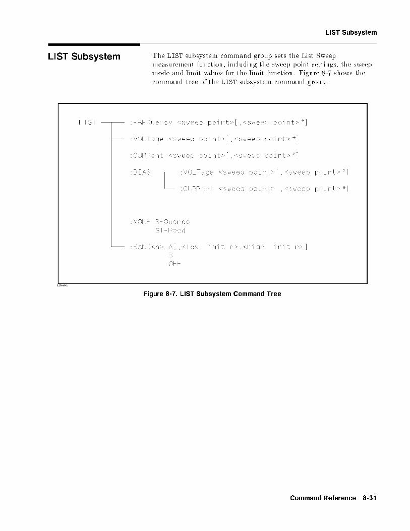
LIST Subsystem
LIST Subsystem The LIST subsystem command group sets the List Sweepmeasurement function, including the sweep point settings, the sweepmode and limit values for the limit function. Figure 8-7 shows thecommand tree of the LIST subsystem command group.
Figure 8-7. LIST Subsystem Command Tree
Command Reference 8-31

LIST Subsystem
:FREQuency The :FREQuency command clears the previous List Sweep pointtable, and sets the frequency sweep points. The :FREQuency? queryreturns the current settings of the frequency sweep points.
Command Syntax LIST:FREQuency <value>�,<value>*
�*Repeat Max. 10 sweep points
Where,<value> is the NR1, NR2, or NR3 format
Example OUTPUT 717;"LIST:FREQ 1E3,2E3,3E3,4E3"
!Set 1kHz to point 1, ..., 4kHz to point 4
Note A su�x multiplier and a su�x unit, HZ (hertz), can be used with thiscommand. Either MAHZ and MHZ can be used as the su�x multiplierfor MHz (1E6 Hz).
Query Syntax LIST:FREQuency?
Query Response Returned format is :
<NR3>�,<NR3>*
�<NL^END>
Example 10 DIM A$[100]
20 OUTPUT 717;"LIST:FREQ?"
30 ENTER 717;A$
40 PRINT A$
50 END
Note If this query is received when the List Sweep parameter is set toanything other than frequency, error �230 Data corrupt or stale
will occur.
8-32 Command Reference

LIST Subsystem
:VOLTage The :VOLTage command clears the previous list sweep point table,and sets the oscillator voltage level sweep points. The :VOLTage?query returns the current settings of the voltage sweep points.
Command Syntax LIST:VOLTage <value>�,<value>*
�*Max. 10 sweep points
Where,<value> is the NR1, NR2, or NR3 format
Example OUTPUT 717;"LIST:VOLT 1.5" !Set 1.5V to point 1
OUTPUT 717;"LIST:VOLT 1E-2,2E-2,3E-2,4E-2"
! Set 10 mV to point 1, .... 40 mV to point 4
Note A su�x multiplier and a su�x unit, V (voltage), can be used withthis command.
Query Syntax LIST:VOLTage?
Query Response Returned format is :
<NR3>�,<NR3>*
�<NL^END>
Example 10 DIM A$[100]
20 OUTPUT 717;"LIST:VOLT?"
30 ENTER 717;A$
40 PRINT A$
50 END
Note If this query is received when the List Sweep parameter is set toanything other than voltage, error �230 Data corrupt or stale willoccur.
Command Reference 8-33

LIST Subsystem
:CURRent The :CURRent command clears the previous list sweep point table,and sets the oscillator current level sweep points. The :CURRent?query returns the current settings of current sweep points.
Command Syntax LIST:CURRent <value>�,<value>*
�*Max. 10 sweep points
Where,<value> is the NR1, NR2, or NR3 format
Example OUTPUT 717;"LIST:CURR 100MA" !Set 100mA to point 1
OUTPUT 717;"LIST:CURR 1E-2,2E-2,3E-2,4E-2"
! Set 10 mA to point 1, ... 40 mA to point 4
Note A su�x multiplier and a su�x unit, A (ampere), can be used withthis command.
Query Syntax LIST:CURRent?
Query Response Returned format is :
<NR3>�,<NR3>*
�<NL^END>
Example 10 DIM A$[100]
20 OUTPUT 717;"LIST:CURR?"
30 ENTER 717;A$
40 PRINT A$
50 END
Note If this query is received when the List Sweep parameter is set toanything other than current, error �230 Data corrupt or stale willoccur.
8-34 Command Reference

LIST Subsystem
:BIAS:VOLTage The :BIAS:VOLTage command clears the previous List Sweeppoint table, and sets the DC bias voltage level sweep points. The:BIAS:VOLTage? query returns the current settings of the DCvoltage sweep points. Refer to Appendix G
Command Syntax LIST:BIAS:VOLTage <value>�,<value>*
�*Max. 10 sweep points
Where,<value> is the NR1, NR2, or NR3 format
Example OUTPUT 717;"LIST:BIAS:VOLT 1.5V" !Set 1.5V to point 1
OUTPUT 717;"LIST:BIAS:VOLT 2E-1,4E-1,6E-1,8E-1"
! Set 200 mV to point 1, ... 800 mV to point 4
Note A su�x multiplier and a su�x unit, V (voltage), can be used withthis command.
Query Syntax LIST:BIAS:VOLTage?
Query Response Returned format is :
<NR3>�,<NR3>*
�<NL^END>
Example 10 DIM A$[100]
20 OUTPUT 717;"LIST:BIAS:VOLT?"
30 ENTER 717;A$
40 PRINT A$
50 END
Note If this query is received when the List Sweep parameter is set toanything other than bias voltage, error �230 Data corrupt or stale
will occur.
Command Reference 8-35

LIST Subsystem
:BIAS:CURRent The :BIAS:CURRent command clears the previous List Sweeppoint table, and sets the DC bias current level sweep points. The:BIAS:CURRent? query returns the current settings of the DCcurrent sweep points.
Command Syntax LIST:BIAS:CURRent <value>�,<value>*
�*Max. 10 sweep points
Where,<value> is the NR1, NR2, or NR3 format
Example
OUTPUT 717;"LIST:BIAS:CURR 100MA" !Set 100mA to point 1
OUTPUT 717;"LIST:BIAS:CURR 1E-2,2E-2,3E-2,4E-2"
! Set 10 mA to point 1, ... 40 mA to point 4
Note A su�x multiplier and a su�x unit, A (ampere), can be used withthis command.
Query Syntax LIST:BIAS:CURRent?
Query Response Returned format is :
<NR3>�,<NR3>*
�<NL^END>
Example 10 DIM A$[100]
20 OUTPUT 717;"LIST:BIAS:CURR?"
30 ENTER 717;A$
40 PRINT A$
50 END
Note If this query is received when the List Sweep parameter is set toanything other than bias current, error �230 Data corrupt or stale
will occur.
8-36 Command Reference

LIST Subsystem
:MODE The :MODE command sets the sweep mode of the List Sweepmeasurement function. The :MODE? query returns the current modesetting of the List Sweep measurement function.
Command Syntax LIST:MODE
�SEQuence
STEPped
�
Where,
SEQuence Sets to sequence modeSTEPped Sets to stepped mode
Example OUTPUT 717;"LIST:MODE SEQ"
Query Syntax LIST:MODE?
Query Response Returned format is :�SEQ
STEP
�<NL^END>
Example 10 OUTPUT 717;"LIST:MODE?"
20 ENTER 717;A$
30 PRINT A$
40 END
Command Reference 8-37

LIST Subsystem
:BAND<n> The :BAND<n> command sets the limit values of the limit functionfor the list sweep measurement. The :BAND<n>? query returns thecurrent limit value settings.
Command Syntax LIST:BAND<n><parameter>�,<low limit n>,<high limit n>
�Where,
<n> 1 to 10 (NR1) : Sweep point number<parameter> is : A Limit setting enable for primary parameter
B Limit setting enable for secondaryparameter
OFF Limit setting disable<low limit n> NR1, NR2, or NR3 format : low limit for sweep
point<n><high limit n> NR1, NR2, or NR3 format : high limit for sweep
point<n>
Example OUTPUT 717;"LIST:BAND1 A,10,20"
OUTPUT 717;"LIST:BAND3 OFF"
Query Syntax LIST:BAND<n>?
Query Response Returned format is :
<parameter>,<low limit n>,<high limit n>
Example 10 DIM A$[30]
20 OUTPUT 717;"LIST:BAND3?"
30 ENTER 717;A$
40 PRINT A$
50 END
8-38 Command Reference

APERture Subsystem
APERtureSubsystem
The APERture command sets the integration time of the A/Dconverter and the averaging rate. The APERture? query returns thecurrent integration time and the averaging rate settings.
Command SyntaxAPERture
8<:
SHORt
MEDium
LONG
9=;�,<value>
�
Where,
SHORt Short integration timeMEDium Medium integration timeLONG Long integration time<value> 1 to 128 (NR1) : Averaging rate
Example OUTPUT 717;"APER SHOR"
OUTPUT 717;"APER MED,64"
Query Syntax APERture?
Query Response Returned format is :8<:
SHOR
MED
LONG
9=;,<NR1><NL^END>
Example 10 OUTPUT 717;"APER?"
20 ENTER 717;A$
30 PRINT A$
40 END
Command Reference 8-39

TRIGger Subsystem The TRIGger subsystem command group is used to enable ameasurement or a sweep measurement, and to set the trigger modeand the trigger delay time. Figure 8-8 shows the command tree ofthe TRIGger subsystem command group.
Figure 8-8. TRIGger Subsystem Command Tree
:IMMediate The :IMMediate command causes the trigger to execute ameasurement or a sweep measurement, regardless of the trigger state.Refer to \Trigger System" in Chapter 7, for details.
Command Syntax TRIGger�:IMMediate
�
Example OUTPUT 717;"TRIG"
OUTPUT 717;"TRIG:IMM"
8-40 Command Reference

TRIGger Subsystem
:SOURce The :SOURce command sets the trigger mode. The :SOURce? queryreturns the current trigger mode.
Command Syntax
TRIGger:SOURce
8>><>>:
INTernal
EXTernal
BUS
HOLD
9>>=>>;
Where,
INTernal Internal trigger modeEXTernal External trigger modeBUS Bus trigger modeHOLD Trigger hold (Manual trigger mode)
Example OUTPUT 717;"TRIG:SOUR BUS"
Query Syntax TRIGger:SOURce?
Query Response Returned format is :8>><>>:
INT
EXT
BUS
HOLD
9>>=>>;<NL^END>
Example 10 OUTPUT 717;"TRIG:SOUR?"
20 ENTER 717;A$
30 PRINT A$
40 END
Command Reference 8-41

TRIGger Subsystem
:DELay The :DELay command sets the trigger delay time. The :DELay?query returns the current delay time.
Command SyntaxTRIGger:DELay
8<:<value>
MIN
MAX
9=;
Where,
<value> is the NR1, NR2, or NR3 format; 0 to 60 [s] in 1 msresolution
MIN Sets the minimum delay value (0 s)MAX Sets the maximum delay value (60 s)
Example OUTPUT 717;"TRIG:DEL 5S" ! Set delay time to 5 s
OUTPUT 717;"TRIG:DEL MIN" ! Set delay time to 0 s
Note A su�x multiplier and a su�x unit, S (second), can be used with thiscommand.
Query Syntax TRIGger:DELay?
�MIN
MAX
�
Query Response Returned Format is :
<NR3><NL^END>
Example 10 OUTPUT 717;"TRIG:DEL?"
20 ENTER 717;A
30 PRINT A
40 END
8-42 Command Reference

INITiate Subsystem
INITiate Subsystem The INITiate subsystem command group controls initiation ofthe triggering system. Figure 8-9 shows the command tree of theINITiate subsystem command group.
Figure 8-9. INITiate Subsystem Command Tree
[:IMMediate] The [:IMMediate] command changes the trigger state to the IDLESTATE to the WAIT FOR TRIGGER STATE for one triggersequence. For details, refer to \Trigger System" in Chapter 7.
Command Syntax INITiate�IMMediate
�
Example OUTPUT 717;"INIT"
OUTPUT 717;"INIT:IMM"
Command Reference 8-43

INITiate Subsystem
:CONTinuous The :CONTinuous command sets the trigger system to theCONTinuous ON or OFF condition. In the CONTinuous ONcondition, after reading the measurement data by a controller, theIDLE STATE is automatically set to the WAIT FOR TRIGGERSTATE. For details refer to \Trigger System" in Chapter 7.The :CONTinuous? query responds the current condition of theCONTinuous ON or OFF.
Command Syntax
INITiate:CONTinuous
8>><>>:
ON
OFF
1
0
9>>=>>;
Where,
1 (decimal 49) When the function is ON0 (decimal 48) When the function is OFF
Example OUTPUT 717;"INIT:CONT ON"
Query Syntax INITiate:CONTinuous?
Query Response Returned format is :
<NR1><NL^END>
Example 10 OUTPUT 717;"INIT:CONT?"
20 ENTER 717;A
30 PRINT A
40 END
8-44 Command Reference

FETCh? Subsystem
FETCh? Subsystem The FETCh? subsystem command group is a sensor-only commandwhich retrieves the measurement data taken by measurement(s)initiated by a trigger, and places the data into the HP 4284A'soutput bu�er.
Figure 8-10 shows the command tree of the FETCh? subsystemcommand group.
Figure 8-10. FETCh? Subsystem Command Tree
[:IMP]? The [:IMP]? query sets the latest measurement data of the primaryand secondary parameters into the HP 4284A's output bu�er. Forthe returned format, refer to \Data Transfer" in Chapter 7.
Query Syntax FETCh�:IMP
�?
Example 10 OUTPUT 717;"TRIG:SOUR BUS"
20 OUTPUT 717;"TRIG"
30 OUTPUT 717;"FETC?"
40 ENTER 717;A,B,C
50 PRINT A,B,C
60 END
Command Reference 8-45

FETCh? Subsystem
:Source MONitor:VAC?
The :Source MONitor:VAC? query sets the latest measured voltagemonitor data into the HP 4284A's output bu�er.
Query Syntax FETCh:SMONitor:VAC?
Query Response Returned format is :
<NR3><NL^END>.
Example 10 OUTPUT 717;"TRIG:SOUR BUS"
20 OUTPUT 717;"TRIG"
30 OUTPUT 717;"FETC:SMON:VAC?"
40 ENTER 717;A
50 PRINT A
60 END
Note If this query is received when the voltage level monitor is set to OFF,returned data is 9.9E37.
:Source MONitor:IAC?
The :Source MONitor:IAC? query sets the latest measured currentmonitor data into the HP 4284A's output bu�er.
Query Syntax FETCh:SMONitor:IAC?
Query Response Returned format is :
<NR3><NL^END>.
Example 10 OUTPUT 717;"TRIG:SOUR BUS"
20 TRIGGER 717
30 OUTPUT 717;"FETC:SMON:IAC?"
40 ENTER 717;A
50 PRINT A
60 END
Note If this query is received when the current level monitor is set to OFF,returned data is 9.9E37.
8-46 Command Reference

ABORt Subsystem
ABORt Subsystem The ABORt command sets the trigger system to reset, and the triggerstate is in the IDLE STATE on the state diagram. For detail, refer to\Trigger System" in Chapter 7.
Command Syntax ABORt
Example OUTPUT 717;"ABOR"
Command Reference 8-47

FORMat Subsystem The FORMat command sets the data output format. For details, referto \Data Transfer" in Chapter 7. The FORmat? query returns thecurrent data format setting.
Command Syntax FORMat�:DATA
��ASCii
REAL�,64
��
Where,
ASCii is set by the ASCII data formatREAL[,64] is set by the IEEE-64 bit oating point data format
Example OUTPUT 717;"FORM REAL"
Query Syntax FORMat�:DATA
�?
Query Response Returned data format is :�ASC
REAL,64
�<NL^END>
Example 10 OUTPUT 717;"FORM?"
20 ENTER 717;A$
30 PRINT A$
40 END
8-48 Command Reference

MEMory Subsystem
MEMory Subsystem The MEMory subsystem command group controls the HP 4284A'sdata bu�er. Figure 8-11 shows the command tree of the MEMorysubsystem command group.
Figure 8-11. MEMory Subsystem Command Tree
:DIM The :DIM command clears the data bu�er memory, and sets the sizeof the data bu�er memory. For details, refer to \Data Transfer" inChapter 7.
Command Syntax MEMory:DIM DBUF,<value>
Where,
<value> 1 to 128 (NR1) : Number of data sets
Example
OUTPUT 717;"MEM:DIM DBUF,3"
! Specify the DBUF size for 3 sets of measurement data
:FILL The :FILL command enables the data bu�er memory to store themeasurement data. After execution of the :FILL command, allmeasurement data will be stored in the data bu�er memory. Fordetails, refer to \Data Transfer" in Chapter 7.
Command Syntax MEMory:FILL DBUF
Example OUTPUT 717;"MEM:FILL DBUF"
Command Reference 8-49

MEMory Subsystem
:CLEar The :CLEar command clears the data bu�er memory. Afterexecution of this command, measurement data will not be stored inthe data bu�er memory until execution of the :FILL command. Fordetails, refer to \Data Transfer" in Chapter 7.
Command Syntax MEMory:CLEar DBUF
Example OUTPUT 717;"MEM:CLE DBUF"
:READ? The :READ? query places the data in the data bu�er memory into theoutput bu�er. If the data bu�er memory is not �lled to the speci�edsize (speci�ed by the :DIM command), the data locations in whichdata is not stored will be set to �1 (no data). For details of thereturned data format, refer to \Data Transfer" in Chapter 7.
Query Syntax MEMory:READ? DBUF
Example OUTPUT 717;"MEM:READ? DBUF"
8-50 Command Reference

CORRection Subsystem
CORRectionSubsystem
The CORRection subsystem command group sets the correctionfunction, including the cable length correction settings, and theOPEN/SHORT/LOAD correction settings. Figure 8-12 shows thecommand tree of the CORRection subsystem command group.
Figure 8-12. CORRection Subsystem Command Tree
Command Reference 8-51

CORRection Subsystem
:LENGth The :LENGth command sets the cable length correction setting. The:LENGth? query returns the current settings of the cable lengthcorrection.
Command Syntax CORRection:LENGth <value>
Where,
<value> 0 , 1, or 2 is Cable length in [m]
Note A su�x with a su�x unit, M (meter), can be used with thiscommand.
Example OUTPUT 717;"CORR:LENG 1M"
Query Syntax CORRection:LENGth?
Query Response Returned format is :
<NR1><NL^END>
Example 10 OUTPUT 717;"CORR:LENG?"
20 ENTER 717;A
30 PRINT A
40 END
8-52 Command Reference

COrrection Subsystem
:METHod The :METHod command sets the correction mode. The :METHod?query returns the current settings of the correction mode.
Command Syntax CORRection:METHod
�SINGle
MULTi
�
Where,
SINGle Sets or returns the single channel correction modeMULTi Sets or returns the multi channel correction mode
Example OUTPUT 717;"CORR:METH MULT"
Query Syntax CORRection:METHod?
Query Response Returned format is :�SING
MULT
�<NL^END>
Example 10 OUTPUT 717;"CORR:METH?"
20 ENTER 717;A$
30 PRINT A$
40 END
:OPEN The :OPEN command executes 51 presetted OPEN correction data
measurement points.
Command Syntax CORRection:OPEN
Example OUTPUT 717;"CORR:OPEN"
Command Reference 8-53

COrrection Subsystem
:OPEN:STATe The :OPEN:STATe command sets the OPEN correction function toON or OFF. The :OPEN:STATe? query returns the current ON/OFFcondition of the OPEN correction.
Command Syntax
CORRection:OPEN:STATe
8>><>>:
ON
OFF
1
0
9>>=>>;
Where,
1 (decimal 49) When the function is ON0 (decimal 48) When the function is OFF
Example OUTPUT 717;"CORR:OPEN:STAT ON"
Query Syntax CORRection:OPEN:STATe?
Query Response Returned format is :
<NR1><NL^END>
Example 10 OUTPUT 717;"CORR:OPEN:STAT?"
20 ENTER 717;A
30 PRINT A
40 END
:SHORt The :SHORt command executes 51 presetted SHORT correction datameasurement points.
Command Syntax CORRection:SHORt
Example OUTPUT 717;"CORR:SHOR"
8-54 Command Reference

COrrection Subsystem
:SHORt:STATe The :SHORt:STATe command sets the SHORT correction functionto ON or OFF. The :SHORt:STATe? query responds the currentON/OFF condition of the SHORT correction.
Command Syntax
CORRection:SHORt:STATe
8>><>>:
ON
OFF
1
0
9>>=>>;
Where,
1 (decimal 49) When the function is ON0 (decimal 48) When the function is OFF
Example OUTPUT 717;"CORR:SHOR:STAT ON"
Query Syntax CORRection:SHORt:STATe?
Query Response Returned format is :
<NR1><NL^END>
Example 10 OUTPUT 717;"CORR:SHOR:STAT?"
20 ENTER 717;A
30 PRINT A
40 END
Command Reference 8-55

COrrection Subsystem
:LOAD:STATe The :LOAD:STATe command sets the LOAD correction functionto ON or OFF. The :LOAD:STATe? query responds the currentON/OFF condition of the LOAD correction.
Command Syntax
CORRection:LOAD:STATe
8>><>>:
ON
OFF
1
0
9>>=>>;
Where,
1 (decimal 49) When the function is ON0 (decimal 48) When the function is OFF
Example OUTPUT 717;"CORR:LOAD:STAT ON"
Query Syntax CORRection:LOAD:STATe?
Query Response Returned format is :
<NR1><NL^END>
Example 10 OUTPUT 717;"CORR:LOAD:STAT?"
20 ENTER 717;A
30 PRINT A
40 END
8-56 Command Reference

COrrection Subsystem
:LOAD:TYPE The :LOAD:TYPE command sets the function of the reference valuesfor the load correction. The :LOAD:TYPE? query responds the currentfunction of the reference values.
Command Syntax CORRection:LOAD:TYPE <function>
Where, <function> is:
CPD Sets function to Cp-D LPRP Sets function to Lp-Rp
CPQ Sets function to Cp-Q LSD Sets function to Ls-DCPG Sets function to Cp-G LSQ Sets function to Ls-QCPRP Sets function to Cp-Rp LSRS Sets function to Ls-Rs
CSD Sets function to Cs-D RX Sets function to R-XCSQ Sets function to Cs-Q ZTD Sets function to Z-� (deg)CSRS Sets function to Cs-Rs ZTR Sets function to Z-� (rad)LPQ Sets function to Lp-Q GB Sets function to G-BLPD Sets function to Lp-D YTD Sets function to Y-� (deg)LPG Sets function to Lp-G YTR Sets function to Y-� (rad)
Example OUTPUT 717;"CORR:LOAD:TYPE CPD"
Query Syntax CORRection:LOAD:TYPE?
Query Response Returned format is :
<function><NL^END>
<function> returns the current function of the reference value, usingthe abbreviations listed above.
Example 10 OUTPUT 717;"CORR:LOAD:TYPE?"
20 ENTER 717;A$
30 PRINT A$
40 END
Command Reference 8-57

COrrection Subsystem
:SPOT<n>:STATe The :SPOT<n>:STATe command sets the speci�ed frequency pointcorrection (FREQ1, FREQ2 or FREQ3) to ON or OFF. The:SPOT<n>:STATe? query responds the current ON/OFF setting ofthe speci�ed frequency point correction.
Command Syntax
CORRection:SPOT<n>:STATe
8>><>>:
ON
OFF
1
0
9>>=>>;
Where,
1 (decimal 49) When the function is ON0 (decimal 48) When the function is OFF
<n> is:
1 State setting for FREQ1 point2 State setting for FREQ2 point3 State setting for FREQ3 point
Example OUTPUT 717;"CORR:SPOT1:STAT ON"
Query Syntax CORRection:SPOT<n>:STATe?
Query Response Returned format is :
<NR1><NL^END>
Example 10 OUTPUT 717;"CORR:SPOT1:STAT?"
20 ENTER 717;A
30 PRINT A
40 END
8-58 Command Reference

COrrection Subsystem
:SPOT<n>:FREQuency
The :SPOT<n>:FREQuency command sets the frequency points(FREQ1, FREQ2 or FREQ3) for the speci�ed frequency pointcorrection. The :SPOT<n>:FREQuency? query returns the currentsettings of the frequency points ( FREQ1, FREQ2 or FREQ3).
Command Syntax CORRection:SPOT<n>:FREQuency <value>
Where,
<value> is the NR1, NR2, or NR3 format
<n> is:
1 Frequency setting for FREQ1 point2 Frequency setting for FREQ2 point3 Frequency setting for FREQ3 point
Example OUTPUT 717;"CORR:SPOT1:FREQ 2KHZ"! Set 2 kHz to FREQ1
Note A su�x multiplier and a su�x unit, HZ (hertz), can be used with thiscommand. Either MAHZ and MHZ can be used as the su�x multiplierfor MHz (1E6 Hz).
Query Syntax CORRection:SPOT<n>:FREQuency?
Query Response Returned format is :
<NR3><NL^END>
Example 10 OUTPUT 717;"CORR:SPOT1:FREQ?"
20 ENTER 717;A
30 PRINT A
40 END
Note If this query is received when the List Sweep parameter is set toanything other than frequency, error �230 Data corrupt or stale
will occur.
Command Reference 8-59

COrrection Subsystem
:SPOT<n>:OPEN The :SPOT<n>:OPEN command executes the OPEN correction datameasurement for the speci�ed frequency point (FREQ1, FREQ2 orFREQ3) correction.
Command Syntax CORRection:SPOT<n>:OPEN
Where,<n> is :
1 State setting for FREQ1 point2 State setting for FREQ2 point3 State setting for FREQ3 point
Example OUTPUT 717;"CORR:SPOT1:OPEN"
:SPOT<n>:SHORt The :SPOT<n>:SHORt command executes the SHORT correction
data measurement for the speci�ed frequency point (FREQ1, FREQ2or FREQ3) correction.
Command Syntax CORRection:SPOT<n>:SHORt
Where, <n> is:
1 State setting for FREQ1 point2 State setting for FREQ2 point3 State setting for FREQ3 point
Example OUTPUT 717;"CORR:SPOT1:SHOR"
8-60 Command Reference

COrrection Subsystem
:SPOT<n>:LOAD The :SPOT<n>:LOAD command executes the LOAD correction datameasurement for the speci�ed frequency point (FREQ1, FREQ2 orFREQ3) correction.
Command Syntax CORRection:SPOT<n>:LOAD
Where,<n> is :
1 State setting for FREQ1 point2 State setting for FREQ2 point3 State setting for FREQ3 point
Example OUTPUT 717;"CORR:SPOT1:LOAD"
Command Reference 8-61

COrrection Subsystem
:SPOT<n>:LOAD:STANdard
The :SPOT<n>:LOAD:STANdard command sets the reference valuesof the standard at the speci�ed frequency point (FREQ1, FREQ2or FREQ3). The :SPOT<n>:LOAD:STANdard? query returns thecurrent settings of the reference values for FREQ1, FREQ2 orFREQ3.
Command Syntax CORRection:SPOT<n>:LOAD:STANdard <REF.A>,<REF.B>
Where,
<n> 1 Setting for FREQ1 point2 Setting for FREQ2 point3 Setting for FREQ3 point
<REF.A> is the NR1, NR2, or NR3 format :Primary parameter's reference value of the standard
<REF.B> is the NR1, NR2, or NR3 format :Secondary parameter's reference value of thestandard
Example OUTPUT 717;"CORR:SPOT1:LOAD:STAN 100.7,0.0002"
Query Syntax CORRection:SPOT<n>:LOAD:STANdard?
Query Response Returned format is :
<NR3>,<NR3><NL^END>
Example 10 OUTPUT 717;"CORR:SPOT1:LOAD:STAN?"
20 ENTER 717;A,B
30 PRINT A,B
40 END
8-62 Command Reference

COrrection Subsystem
:USE The :USE command sets the channel number to be used for multichannel correction. The :USE? query returns the current settings ofthe channel selected.
Command Syntax CORRection:USE <channel number>
Where, <channel number> is : 1 to 127 (NR1, NR2, or NR3) :channel number
Example OUTPUT 717;"CORR:USE 10" ! Set to channel number 10
Query Syntax CORRection:USE?
Query Response Returned format is :
<channel number><NL^END>
Example 10 OUTPUT 717;"CORR:USE?"
20 ENTER 717;A
30 PRINT A
40 END
Command Reference 8-63

COrrection Subsystem
:USE:DATA? The :USE:DATA? query returns the OPEN/SHORT/LOAD correctionmeasurement data at FREQ1, FREQ2 or FREQ3.
Query Syntax CORRection:USE:DATA? <channel number>
Where, <channel number> is : 1 to 127 (NR1)
Query Response Returned format is :<open1 A>, <open1 B>, <short1 A>, <short1 B>, <load1 A>,<load1 B>,<open2 A>, <open2 B>, <short2 A>, <short2 B>, <load2 A>,<load2 B>,<open3 A>, <open3 B>, <short3 A>, <short3 B>, <load3 A>,<load3 B>,
Where,
<open1/2/3 A> NR3 format : primary OPEN correction data atFREQ1/2/3.
<open1/2/3 B> NR3 format : secondary OPEN correction data atFREQ1/2/3.
<short1/2/3 A> NR3 format : primary SHORT correction data atFREQ1/2/3.
<short1/2/3 B> NR3 format : secondary SHORT correction dataat FREQ1/2/3.
<load1/2/3 A> NR3 format : primary LOAD correction data atFREQ1/2/3.
<load1/2/3 B> NR3 format : secondary LOAD correction data atFREQ1/2/3.
Example 10 OPTION BASE 1
20 DIM A(18)
30 OUTPUT 717;"CORR:USE:DATA? 89"
40 ENTER 717;A(*)
50 PRINT A(*)
60 END
8-64 Command Reference

COMParator Subsystem
COMParatorSubsystem
The COMParator subsystem command group sets the comparatorfunction, including its ON/OFF setting, limit mode, and limit values.Figure 8-13 shows the command tree of the COMParator subsystemcommand group.
Figure 8-13. COMParator Subsystem Command Tree
Command Reference 8-65

COMParator Subsystem
[:STATe] The [:STATe] command sets the comparator function to ON orOFF. The [:STATe]? query responds the current ON/OFF conditionof comparator function.
Command Syntax
COMParator�:STATe
�8>><>>:
ON
OFF
1
0
9>>=>>;
Where,
1 (decimal 49) When the function is ON0 (decimal 48) When the function is OFF
Example OUTPUT 717;"COMP ON"
Query Syntax COMParator�:STATe
�?
Query Response Returned format is :
<NR1><NL^END>
Example 10 OUTPUT 717;"COMP?"
20 ENTER 717;A
30 PRINT A
40 END
8-66 Command Reference

COMParator Subsystem
:MODE The :MODE command sets the limit mode of the comparator function.The :MODE? query returns the current settings of the limit mode.
Command SyntaxCOMParator:MODE
8<:
ATOLerance
PTOLerance
SEQuence
9=;
Where,
ATOLerance Set the absolute tolerance mode (parameter value)PTOLerance Set the percent tolerance mode (the ratio in percent)SEQuence Set the sequential mode
Example OUTPUT 717;"COMP:MODE ATOL"
Query Syntax COMParator:MODE?
Query Response Returned format is:8<:
ATOL
PTOL
SEQ
9=;<NL^END>
Example 10 OUTPUT 717;"COMP:MODE?"
20 ENTER 717;A$
30 PRINT A$
40 END
Command Reference 8-67
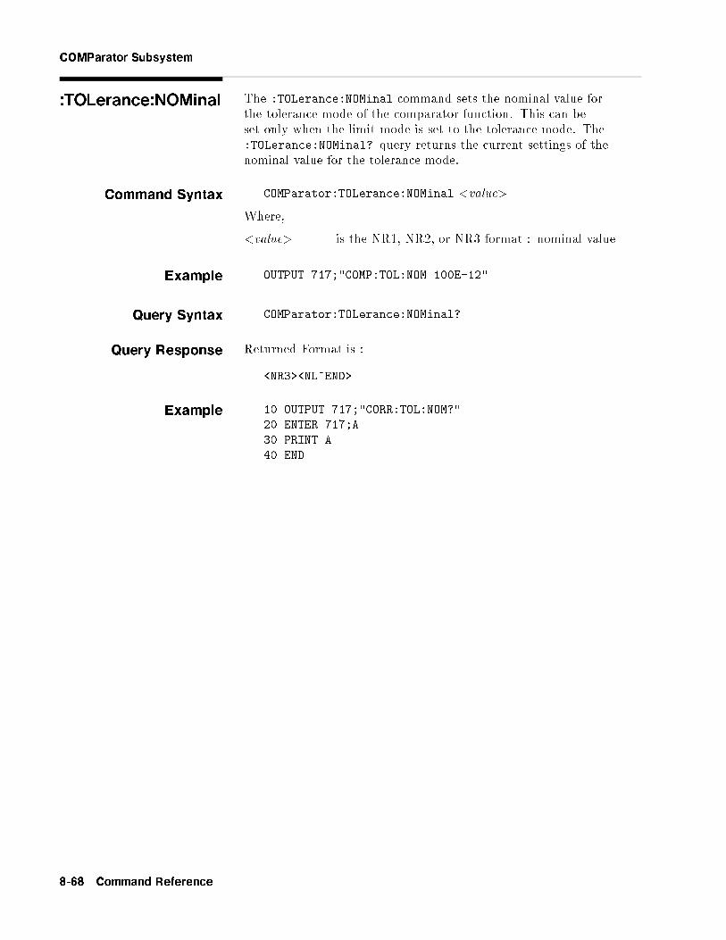
COMParator Subsystem
:TOLerance:NOMinal The :TOLerance:NOMinal command sets the nominal value forthe tolerance mode of the comparator function. This can beset only when the limit mode is set to the tolerance mode. The:TOLerance:NOMinal? query returns the current settings of thenominal value for the tolerance mode.
Command Syntax COMParator:TOLerance:NOMinal <value>
Where,
<value> is the NR1, NR2, or NR3 format : nominal value
Example OUTPUT 717;"COMP:TOL:NOM 100E-12"
Query Syntax COMParator:TOLerance:NOMinal?
Query Response Returned Format is :
<NR3><NL^END>
Example 10 OUTPUT 717;"CORR:TOL:NOM?"
20 ENTER 717;A
30 PRINT A
40 END
8-68 Command Reference

COMParator Subsystem
:TOLerance:BIN<n> The :TOLerance:BIN<n> command sets the low/high limit values ofeach BIN for the comparator function tolerance mode. These limitscan be set only when the limit mode is set to the tolerance mode.The :TOLerance:BIN<n> query returns the current settings of thelow/high limit values of each of the BINs.
Command Syntax COMParator:TOLerance:BIN<n> <low limit>,<high limit>
Where,
<n> 1 to 9 (NR1) : BIN number<low limit> NR1, NR2, or NR3 format : low limit value<high limit> NR1, NR2, or NR3 format : high limit value
Note The low limit value should be lower than the high limit value. If thelow limit value is set higher than the high limit, a warning message isdisplayed when this command is received (an error does not occur).
Example OUTPUT 717;"COMP:TOL:BIN1 -5,5"
OUTPUT 717;"COMP:TOL:BIN2 -10,10"
Query Syntax COMParator:TOLerance:BIN<n>?
Query Resopnse Returned Format is :
<low limit>,<high limit><NL^END>
Example 10 OUTPUT 717;"COMP:TOL:BIN1?"
20 ENTER 717;A,B
30 PRINT A,B
40 END
Command Reference 8-69

COMParator Subsystem
:SEQuence:BIN The :SEQuence:BIN command sets the low/high limit values of theBINs for the sequence mode of the comparator function. Theselimits can be set only when the limit mode is set to the sequencemode. The :SEQuence:BIN query returns the current settings of thelow/high limit values of the BINs.
Command SyntaxCOMParator:SEQuence:BIN <BIN1 low limit>,<BIN1 high
limit>,<BIN2 high limit>, . . . , <BINn high limit>
Where,
<BIN1 low limit> NR1, NR2, or NR3 format : low limit value forBIN1
<BIN1 high limit> NR1, NR2, or NR3 format : high limit valuefor BIN1
<BINn high limit> NR1, NR2, or NR3 format : high limit valuefor BINn (n : max. 9 )
Note The low limit value should be lower than the high limit value.
Example OUTPUT 717;"COMP:SEQ:BIN 10,20,30,40,50"
Query Syntax COMParator:SEQuence:BIN?
Query Response Returned Format is :
<BIN1 low limit>,<BIN1 high limit>,<BIN2 high limit>, . . . ,<BINn high limit><NL^END>
Example 10 DIM A$[200]
20 OUTPUT 717;"COMP:SEQ:BIN?"
30 ENTER 717;A$
40 PRINT A$
50 END
8-70 Command Reference

:Secondary LIMit
:Secondary LIMit The :Secondary LIMit command sets the low/high limit values forthe comparator function secondary parameter. The :SecondaryLIMit? query returns the current settings of the secondaryparameter low/high limit values.
Command Syntax COMParator:SLIMit <low limit>,<high limit>
Where,
<low limit> is the NR1, NR2, or NR3 format : low limit value<high limit> is the NR1, NR2, or NR3 format : high limit value
Note The low limit value should be lower than the high limit value. If thelow limit value is set higher than the high limit, a warning message isdisplayed when this command is received (an error does not occur).
Example OUTPUT 717;"COMP:SLIM 0.001,0.002"
Query Syntax COMParator:SLIMit?
Query Response Returned Format is:
<NR3>,<NR3><NL^END>
Example 10 OUTPUT 717;"COMP:SLIM?"
20 ENTER 717;A,B
30 PRINT A,B
40 END
Command Reference 8-71

:Secondary LIMit
:Auxiliary BIN The :Auxiliary BIN command sets the auxiliary BIN countingfunction of the comparator to ON or OFF. The :Auxiliary BIN
query responds the current ON/OFF condition of the auxiliary BINcounting function.
Command Syntax
COMParator:Auxiliary BIN
8>><>>:
ON
OFF
1
0
9>>=>>;
Where,
0 (decimal 48) When the function is OFF1 (decimal 49) When he function is ON
Example OUTPUT 717;"COMP:ABIN ON"
Query Syntax COMParator:Auxiliary BIN?
Query Response Returned Format is :
<NR1><NL^END>
Example 10 OUTPUT 717;"COMP:ABIN?"
20 ENTER 717;A
30 PRINT A
40 END
8-72 Command Reference

COMParator Subsystem
:SWAP The :SWAP command sets the swap parameter function to ON (9BIN settings for secondary parameter) or OFF (9 BIN settingsfor primary parameter). The :SWAP? query responds the currentON/OFF condition of the auxiliary BIN counting function.
Command Syntax
COMParator:SWAP
8>><>>:
ON
OFF
1
0
9>>=>>;
Where,
0 (decimal 48) When the function is OFF1 (decimal 49) When the function is ON
Example OUTPUT 717;"COMP:SWAP ON"
Query Syntax COMParator:SWAP?
Query Response Returned Format is :
<NR1><NL^END>
Example 10 OUTPUT 717;"COMP:SWAP?"
20 ENTER 717;A
30 PRINT A
40 END
:BIN:CLEar The :BIN:CLEar command clears all of the limit value settings.
Command Syntax COMParator:BIN:CLEar
Example OUTPUT 717;"COMP:BIN:CLE"
Command Reference 8-73
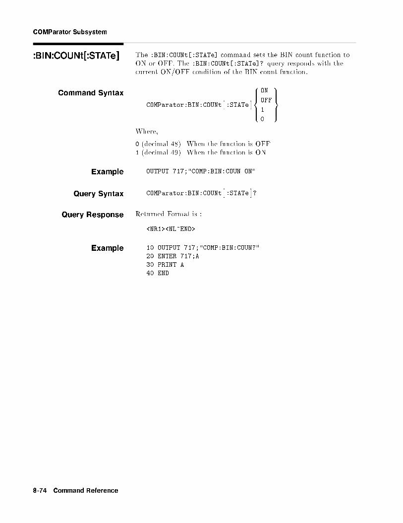
COMParator Subsystem
:BIN:COUNt[:STATe] The :BIN:COUNt[:STATe] command sets the BIN count function toON or OFF. The :BIN:COUNt[:STATe]? query responds with thecurrent ON/OFF condition of the BIN count function.
Command Syntax
COMParator:BIN:COUNt�:STATe
�8>><>>:
ON
OFF
1
0
9>>=>>;
Where,
0 (decimal 48) When the function is OFF1 (decimal 49) When the function is ON
Example OUTPUT 717;"COMP:BIN:COUN ON"
Query Syntax COMParator:BIN:COUNt�:STATe
�?
Query Response Returned Format is :
<NR1><NL^END>
Example 10 OUTPUT 717;"COMP:BIN:COUN?"
20 ENTER 717;A
30 PRINT A
40 END
8-74 Command Reference

COMParator Subsystem
:BIN:COUNt:DATA? The :BIN:COUNt:DATA? query returns the comparator BIN countresults.
Query Syntax COMParator:BIN:COUNt:DATA?
Query Response Returned Format is :
<BIN1 count>,<BIN2 count>, . . . , <BIN9 count>,<OUT OF
BIN count>, <AUX BIN count><NL^END>
Where,
<BIN1{9 count> NR1 format : count result of BIN1{9<OUT OF BINS count> NR1 format : count result of OUT OF
BINS<AUX BIN count> NR1 format : count result of AUX
BIN
Example 10 OPTION BASE 1
20 DIM A(11)
30 OUTPUT 717;"COMP:BIN:COUN:DATA?"
40 ENTER 717;A(*)
50 PRINT A(*)
60 END
:BIN:COUNt:CLEar The :BIN:COUNt:CLEar command clears all BIN counts.
Command Syntax COMParator:BIN:COUNt:CLEar
Example OUTPUT 717;"COMP:BIN:COUN:CLE"
Command Reference 8-75

Mass MEMorySubsystem
The Mass MEMory subsystem command group loads or stores settingdata from/to the internal EEPROM and the external memory card.Figure 8-14 shows the command tree of the Mass MEMory subsystemcommand group.
Figure 8-14. Mass MEMory Subsystem Command Tree
:LOAD:STATe The :LOAD:STATe command loads the setting data from the internalEEPROM or a memory card.
Command Syntax MMEMory:LOAD:STATe <value>
Where,
<value> 0 to 9 (NR1) : record number for internal EEPROM10 to 19 (NR1) : record number for memory card
Example OUTPUT 717;"MMEM:LOAD:STAT 10"
:STORe:STATe The :STORe:STATe command stores the setting data to the internalEEPROM or to the memory card.
Command Syntax MMEMory:STORe:STATe <value>
Where,
<value> 0 to 9 (NR1) : record number for EEPROM10 to 19 (NR1) : record number for memory card
Example OUTPUT 717;"MMEM:STOR:STAT 5"
8-76 Command Reference

SYSTem:ERRor?
SYSTem:ERRor? The SYSTem:ERRor? query returns the existing error numbers withthe error messages for the errors in the HP 4284A's error queue.
The HP 4284A's error queue stores errors generated by theHP 4284A. As errors are generated, they are placed in the errorqueue which stores up to �ve errors. This is a �rst in, �rst out queue(fifo).
If the error queue over ows, the last error in the queue is replacedwith error �350, "Too many errors". Anytime the queue over ows,the least recent errors remain in the queue, and the most recenterrors are discarded.
When all errors have been read from the queue, furtherSYSTem:ERRor? queries will return error 0, "no errors". Readingan error from the queue removes that error from the queue, openinga position in the queue for a new error, if one is subsequentlygenerated.
Query Syntax SYSTem:ERRor?
Query Response Returned Format is :
<number>,"<message>"
Where,
<number> NR1 format : error numberFor details, refer to Appendix B.
<message> ASCII string : error messageFor details, refer to Appendix B.
Example 10 DIM A$[50]
20 FOR I=1 to 5
30 OUTPUT 717;"SYST:ERR?"
40 ENTER 717;A$
50 PRINT A$
60 NEXT I
70 END
Command Reference 8-77

STATus Subsystem The STATus subsystem command group sets the Operation StatusRegisters which report events which are part of the HP 4284A'snormal operation, including measuring and sweeping. Figure 8-15shows the command tree of the STATus subsystem command group.
Figure 8-15. STATus Subsystem Command Tree
8-78 Command Reference

STATus Subsystem
:OPERa-tion[:EVENt]?
The :OPERation[:EVENt]? query returns the contents of thestandard operation status event register. Reading the event registerusing this query has the e�ect of clearing its contents, but has noe�ect on the operation status condition register.
Query Syntax STATus:OPERation�:EVENt
�?
Query Response Returned Format is :
<value><NL^END>
Where,
<value> NR1 format : decimal expression of the contents of theoperation status event register
The de�nition of each bit of the operation status event register is asfollows.
Bit No. Description
15 { 5 Always 0 (zero)
4 Measurement Complete Bit
3 List Sweep Measurement Complete Bit
2, 1 Always 0 (zero)
0 Correction Data Measurement Complete Bit
Example 10 OUTPUT 717;"STAT:OPER?"
20 ENTER 717;A
30 PRINT A
40 END
Command Reference 8-79

STATus Subsystem
:OPERa-tion:CONDition?
The :OPERation:CONDition? query returns the contents of thestandard operation status condition register. Reading a conditionregister using this query does not clear its contents.
Query Syntax STATus:OPERation:CONDition?
Query Response Returned Format is :
<value><NL^END>
Where,
<value> NR1 format : decimal expression of the contents of theoperation status condition register
The de�nition of each bit in the operation status condition register isas follows.
Bit No. Description
15 { 5 Always 0 (zero)
4 Measuring Bit
3 Sweeping Bit
2, 1 Always 0 (zero)
0 Measuring Correction Data Bit
Example 10 OUTPUT 717;"STAT:OPER:COND?"
20 ENTER 717;A
30 PRINT A
40 END
8-80 Command Reference

STATus Subsystem
:OPERation:ENABle The :OPERation:ENABle command sets the enable bits of thestandard operation status event register that allows true conditionsin the event register to be reported in the summary bit of the statusbyte register. The :OPERation:ENABle? query returns the currentsetting of the enable bits of the operation status event register.
Command Syntax STATus:OPERation:ENABle <value>
Where,
<value> NR1 format : decimal expression of enable bits of theoperation status event register
The de�nition of each bit in the operation status event register is asfollows.
Bit No. Description
15 { 5 Always 0 (zero)
4 Measurement Complete Bit
3 List Sweep Measurement Complete Bit
2, 1 Always 0 (zero)
0 Correction Data Measurement Complete Bit
Example OUTPUT 717;"STAT:OPER:ENAB 16"! Bit 4 enable
Query Syntax STATus:OPERation:ENABle?
Query Response Returned Format is:
<value><NL^END>
Example 10 OUTPUT 717;"STAT:OPER:ENAB?"
20 ENTER 717;A
30 PRINT A
40 END
Command Reference 8-81

Common Commands The HP-IB Common commands are de�ned as IEEE 488.2-1987, andare noninstrument speci�c HP-IB commands. A common commandconsists of an asterisk (*) and a header. The HP 4284A acceptableHP-IB common commands are as follows.
HP-IB Common Commands
� *CLS � *SRE � *OPC? � *TST?
� *ESE � *STB? � *WAI � *TRG
� *ESR? � *IDN? � *RST � *LRN?
� *OPT?
*CLS The *CLS command (clear status command) clears the status byteregister, the event register of the standard operation status registerstructure, and the standard event status register. It also clears theerror queue (refer to the description of the SYSTem:ERRor? query).
Command Syntax *CLS
Example OUTPUT 717;"*CLS"
8-82 Command Reference

*ESE The *ESE command (standard Event Status Enable command) setsthe enable bits of the standard event status register. The *ESE?query returns the current setting of the enable bits of the eventstatus register.
Command Syntax *ESE <value>
Where,
<value> NR1 format : decimal expression of enable bits of theoperation status register
The de�nition of each bit in the event status register is as follows.
Bit No. Description
7 Power On (PON) Bit
6 User Request (URQ) Bit
5 Command Error (CME) Bit
4 Execution Error (EXE) Bit
3 Device Dependent Error (DDE) Bit
2 Query Error (QYE) Bit
1 Request Control (RQC) Bit
0 Operation Complete (OPC) Bit
Example OUTPUT 717;"*ESE 36"! Bit 2 and 5 enabled
Query Syntax *ESE?
Query Response Returned format is :
<value><NL^END>
Example 10 OUTPUT 717;"*ESE?"
20 ENTER 717;A
30 PRINT A
40 END
Command Reference 8-83

*ESR? The *ESR? query returns the contents of the standard event statusregister. Using the *ESR query command to read the standard eventstatus register clears its contents.
Query Syntax *ESR?
Query Response Returned format is :
<value><NL^END>
Where,
<value> NR1 format : decimal expression of the contents of theevent status register
The de�nition of each bit of the event status register is as follows.
Bit No. Description
7 Power On (PON) Bit
6 User Request (URQ) Bit
5 Command Error (CME) Bit
4 Execution Error (EXE) Bit
3 Device Dependent Error (DDE) Bit
2 Query Error (QYE) Bit
1 Request Control (RQC) Bit
0 Operation Complete (OPC) Bit
Example 10 OUTPUT 717;"*ESR?"
20 ENTER 717;A
30 PRINT A
40 END
8-84 Command Reference

*SRE The *SRE command (Service Request Enable command) sets theenable bits of the status byte register. The *SRE? query returns thecurrent setting of the status byte register.
Command Syntax *SRE <value>
Where,
<value> NR1 format : decimal expression of enable bits of thestatus byte register
The de�nition of each bit of the status byte register is as follows.
Bit No. Description
7 Operation Status Register Summary Bit
6 RQS (Request Service) Bit
5 Standard Event Status Register Summary Bit
4 MAV (Message Available) Bit
3 { 0 Always 0 (zero)
Example OUTPUT 717;"*SRE 32"! Bit 5 enabled
Query Syntax *SRE?
Query Response Returned format is :
<value><NL^END>
Example 10 OUTPUT 717;"*SRE?"
20 ENTER 717;A
30 PRINT A
40 END
Command Reference 8-85

*STB? The *STB? query reads the status byte by reading the mastersummary status (MSS) bit. These bits represent the contents of thestatus byte register. Execution of the *STB query command has noe�ect on the contents of the status byte register.
Query Syntax *STB?
Query Response Returned format is :
<value><NL^END>
Where,
<value> NR1 format : decimal expression of the contents of thestatus byte register
The de�nition of each bit of the status byte is as follows.
Bit No. Description
7 Operation Status Register Summary Bit
6 RQS (Request Service) Bit
5 Standard Event Status Register Summary Bit
4 MAV (Message Available) Bit
3 { 0 Always 0 (zero)
Example 10 OUTPUT 717;"*STB?"
20 ENTER 717;A
30 PRINT A
40 END
8-86 Command Reference

*IDN?
*IDN? The *IDN? query returns the HP 4284A ID.
Query Syntax *IDN?
Query Response Returned format is :
<manufacturer>,<model>,<serial no.>,<�rmware><NL^END>
Where,
<manufacturer> HEWLETT-PACKARD<model> 4284A<serial number> 0 (not available)<�rmware> REVdd.dd
(dd.dd : ROM �rmware revision number)
Example 10 DIM A$[30]
20 OUTPUT 717;"*IDN?"
20 ENTER 717;A$
30 PRINT A$
40 END
Note This string data is an arbitrary ASCII response. So, this commandshould not be sent before a normal query in a program message. (Forexample, *IDN?;FREQ? can not accepted, FREQ?;*IDN? should besent.)
Command Reference 8-87

*IDN?
*OPC The *OPC command (operation complete command) tells theHP 4284A to set bit 0 (OPC bit) in the standard event statusregister when it completes all pending operations. The *OPC?command tells the HP 4284A to place an ASCII \1" (decimal 49)in the HP 4284A's output bu�er when it completes all pendingoperations.
Command Syntax *OPC
Example
OUTPUT 717;"*OPC" ! Set the HP 4284A to set OPC bit
! when the operation executed by previous command is completed.
Query Syntax *OPC?
Query Response Returned format is :
1<NL^END>
Where,
1 1 (ASCII, decimal 49)
Example
10 OUTPUT 717;"CORR:OPEN" ! Perform OPEN correction measurement
20 OUTPUT 717;"*OPC?" ! Wait for OPEN correction
30 ENTER 717;A ! measurement completed
40 END
*WAI The *WAI command (the wait to continue command) makes theHP 4284A wait until all previously sent commands are completed.The HP 4284A then continues executing the commands that followthe *WAI command.
Command Syntax *WAI
Example OUTPUT 717;"*WAI"
8-88 Command Reference

*RST The *RST command (reset command) sets the HP 4284A to its initialsettings. The initial settings set by the *RST command are givenin Appendix C. When the HP 4284A receives a *RST command,it aborts all pending operations, and forgets about any previouslyreceived *OPC commands and *OPC? queries.
Command Syntax *RST
Example OUTPUT 717;"*RST"
*TST? The *TST? query (self-test query) causes the device to execute aninternal self-test and reports whether or not it detected any errors.In the case of the HP 4284A, the response to this query is always \0"(no error).
Query Syntax *TST?
Query Response Returned format is :
0<NL^END>
Where,
0 0 (NR1 format)
Example 10 OUTPUT 717;"*TST?"
20 ENTER 717;A
30 END
Command Reference 8-89

*TRG The *TRG command (trigger command) performs the same functionas the Group Execute Trigger command (refer to \Trigger System" inChapter 7). This command also moves the primary and secondaryparameter measurement data into the HP 4284A's output bu�er.
Command Syntax *TRG
Example 10 OUTPUT 717;"*TRG"
20 ENTER 717;A,B,C
30 PRINT A,B,C
40 END
8-90 Command Reference

*LRN? The *LRN? query (learn device setup query) tells the HP 4284A tosend a response that contains all the necessary commands to set theHP 4284A to its present state. The response can later be sent backto the HP 4284A to place it in this state. This provides the user witha means of setting up a device manually and then reading the devicesetting and storing the information for later use.
Query Syntax *LRN?
Query Response Returned format is :
:FREQ <NR3>;:VOLT (or CURR) <NR3>;
:AMPL:ALC {0|1};:OUTP:HPOW {0|1};DC:ISOL {0|1};
:BIAS:VOLT (or CURR) <NR3>:STAT {0|1};
:CORR:LENG <NR1>;METH {SING|MULT};
:CORR:OPEN:STAT {0|1};:CORR:SHOR:STAT {0|1};
:CORR:LOAD:STAT {0|1};TYPE <function>;:CORR:SPOT1:STAT {0|1};FREQ <NR3>; LOAD:STAN <REF.A>,<REF.B>;
:CORR:SPOT2:STAT {0|1};FREQ <NR3>; LOAD:STAN <REF.A>,<REF.B>;
:CORR:SPOT3:STAT {0|1};FREQ <NR3>; LOAD:STAN <REF.A>,<REF.B>;:CORR:USE <NR1>;
:FUNC:IMP:TYPE <function>;RANG <NR3>;RANG:AUTO {0|1};
:FUNC:SMON:VAC:STAT {0|1};FUNC:SMON:IAC:STAT {0|1};
:FUNC:DEV1:MODE {ABS|PERC|OFF};REF <NR3>;
:FUNC:DEV2:MODE {ABS|PERC|OFF};REF <NR3>;
:APER {SHOR|MED|LONG},<NR1>;
:TRIG:SOUR {INT|EXT|BUS|HOLD};DEL <NR3>;
:DISP:PAGE <page name>;LINE "<string>";
:FORM {ASC|REAL,64};
:COMP:STAT {0|1};MODE {ATOL|PTOL|SEQ};TOL:NOM <NR3>;
(BIN1 <low>,<high>;BIN2 <low>,<high>, . . . ;) or(:COMP:SEQ:BIN <BIN1 low>,<BIN2 high>,<BIN3 high>,..;)
[:COMP:SLIM <low>,<high>;]
:COMP:ABIN {0|1};SWAP {0|1};BIN:COUN {0|1};
:LIST:FREQ (VOLT, CURR, BIAS:VOLT, or BIAS:CURR) <NR3>[,<NR3>*];:LIST:MODE {SEQ|STEP};
BAND1 <parameter>,<low>,<high>;BAND2 <parameter>,<low>,<high>;...;
BAND<n> <parameter>,<low>,<high>
For details, refer to each command reference page.
Example 10 DIM A$[1000]
20 OUTPUT 717;"*LRN?"
30 ENTER 717;A$
40 !
50 OUTPUT 717;A$
60 END
Command Reference 8-91

*OPT? The *OPT? query (OPTion identi�cation query) tells the HP 4284Ato identify the options installed in the system interface.
Query Syntax *OPT?
Query Response Returned format is :
<power amp>,<I bias IF>,<2m/4m cable>,<handler
I/F>,<scanner I/F><NL^END>
Where,
<power amp> is : 001 (ASCII) : Option 001 is installed0 (ASCII) : Option 001 is not installed
<I bias I/F> is : 002 (ASCII) : Option 002 is installed0 (ASCII) : Option 002 is not installed
<2m/4m cable> is : 006 (ASCII) : Option 006 is installed0 (ASCII) : Option 006 is not installed
<handler I/F> is : 201 (ASCII) : Option 201 is installed
202 (ASCII) : Option 202 is installed0 (ASCII) : Option 201 and 202 are not installed
<scanner I/F> is : 301 (ASCII) : Option 301 is installed
0 (ASCII) : Option 301 is not installed
Note This string data is the arbitrary ASCII response. So this commandshould not be sent before a normal query in a program message. (Forexample, *OPT?;FREQ? can not accepted, FREQ?;*OPT? should besent.)
Example 10 OUTPUT 717;"*OPT?"
20 ENTER 717;A$
30 END
8-92 Command Reference

9
General Information
Introduction This chapter describes speci�cations, supplemental performancecharacteristics, storage/repackaging, and other general informationabout the HP 4284A.
Components notCovered byWarranty
The memory card is not covered under the HP 4284A's warranty. Ifthe memory card becomes defective even within the warranty periodof the HP 4284A, the memory card must be paid for by the user.
Serial Number Hewlett-Packard uses a two-section, nine character serial numberwhich is stamped on the serial number plate (Figure 9-1) attachedto the instrument's rear panel. The �rst four digits and a letter arethe serial number pre�x, and the last �ve digits are the su�x. Theletter placed between the two sections identi�es the country wherethe instrument was manufactured. The pre�x is the same for allidentical instruments; it changes only when a change is made to theinstrument. The su�x, however, is assigned sequentially and isdi�erent for each instrument. The contents of this manual apply toinstruments with the serial number pre�x(es) listed under the serialnumbers on the title page.
Figure 9-1. Serial Number Plate
An instrument manufactured after the printing of this manualmay have a serial number pre�x that is not listed on the titlepage. This unlisted serial number pre�x indicates the instrumentis di�erent from those described in this manual. The manual forthis new instrument may be accompanied by a yellow Manual
General Information 9-1

Change supplement or have a di�erent manual part number. Thissheet contains \change information" that explains how to adapt themanual to the newer instrument.
In addition to change information, the supplement may containinformation for correcting errors (Errata) in the manual. To keepthis manual as current and accurate as possible, Hewlett-Packardrecommends that you periodically request the latest Manual Changessupplement. The supplement for this manual is identi�ed by thismanual's printing date and its part number, both of which appear onthe manual's title page. Complimentary copies of the supplement areavailable from Hewlett-Packard. If the serial pre�x or number of aninstrument is lower than that on the title page of this manual, seeAppendix A, MANUAL CHANGES .
For information concerning, a serial number pre�x that is not listedon the title page or in the Manual Change supplement, contact thenearest Hewlett-Packard o�ce.
Specifications The complete HP 4284A speci�cations are listed below. Thesespeci�cations are the performance standards or limits againstwhich the instrument is tested. When shipped from the factory,the HP 4284A meets the speci�cations listed in this section. Thespeci�cation test procedures are covered in Chapter 10.
Measurement FunctionsMeasurement Parameters
jZj : Absolute value of impedance
jYj : Absolute value of admittanceL : Inductance
C : CapacitanceR : ResistanceG : ConductanceD : Dissipation factorQ : Quality factorRs : Equivalent series resistance
Rp : Parallel resistanceX : Reactance
B : Susceptance� : Phase angle
Combinations
jZj, jYj L, C R G
�(deg), �(rad) D, Q, Rs, Rp, G X B
9-2 General Information

Mathematical Functions
The deviation and the percent of deviation of measurement valuesfrom a programmable reference value.
Equivalent Measurement Circuit
Parallel and Series
Ranging
Auto and Manual (Hold/Up/Down)
Trigger
Internal, External, BUS (HP-IB), and Manual.
Delay Time
Programmable delay from the trigger command to the start of themeasurement, 0 to 60.000 sec. in 1 msec. steps.
Measurement terminals
Four-terminal pair
Test Cable Length
Standard. 0 m and 1 m selectable
With Option 006. 0 m, 1 m, 2 m and 4 m selectable
Integration Time
Short, Medium and Long (See Supplemental PerformanceCharacteristics for the measurement time.)
Averaging
1 to 256, programmable
Test SignalFrequency
20 Hz to 1 MHz, 8610 selectable frequencies (refer to Appendix F forselectable frequencies.)
Accuracy. �0.01%
Signal Modes
Normal. Programs selected voltage or current at the measurementterminals when they are opened or shorted, respectively.
Constant. Maintains selected voltage or current at the device undertest independent of changes in the device's impedance.
General Information 9-3

Signal Level
Mode Range Setting Accuracy
Voltage Non-constant 5 mVrms to 2 Vrms �(10% + 1 mVrms)
Constant1 10 mVrms to 1 Vrms �(6% + 1 mVrms)
Current Non-constant 50 �Arms to 20 mArms �(10% + 10 �Arms)
Constant1 100 �Arms to 10 mArms �(6% + 10 �Arms)
1 Automatic Level Control Function is set to ON.
Output Impedance
100 , �3%
Test Signal Level Monitor
Mode Range Accuracy
Voltage1 5 mVrms to 2 Vrms �(3% of reading + 0.5 mVrms)
0.01 mVrms to 5 mVrms �(11% of reading + 0.1 mVrms)
Current2 50 �Arms to 20 mArms �(3% of reading + 5 �Arms)
0.001 �Arms to 50 �Arms �(11% of reading + 1 �Arms)
1 Add the impedance measurement accuracy [%] to the voltage level monitor
accuracy when the DUT's impedance is < 100 .
2 Add the impedance measurement accuracy [%] to the current level monitor
accuracy when the DUT's impedance is � 100 .
Accuracies apply when test cable length is 0 m or 1 m. additionalerror when test cable length is 2 m or 4 m is given as:
fm �L
2[%]
Where, fm is test frequency [MHz],L is test cable length [m].
Example DUT's impedance : 50 Test signal level : 0.1 Vrms
Measurement accuracy : 0.1 %
Then, Voltage level monitor accuracy is�(3.1 % of reading+0.5 mVrms)
9-4 General Information

Display RangeParameter Range
jZj, R, X 0.01 m to 99.9999 M
jYj, G, B 0.01 nS to 99.9999 S
C 0.01 fF to 9.99999 F
L 0.01 nH to 99.9999 kH
D 0.000001 to 9.99999
Q 0.01 to 99999.9
� �180.000 � to 180.000 �
� �999.999% to 999.999%
Absolute MeasurementAccuracy
Absolute measurement accuracy is given as the sum of the relativemeasurement accuracy plus the calibration accuracy.
jZj, jYj, L, C, R, X, G and B Accuracy
jZj, jYj, L, C, R, X, G and B accuracy is given as,
Ae + Acal [%]
Where, Ae is the relative accuracy,Acal is the calibration accuracy.
L, C, X and B accuracies apply when Dx (measured D value) � 0.1.R and G accuracies apply when Qx (measured Q value) � 0.1.G accuracy described in this paragraph applies to the G-Bcombination only.
D accuracy
D accuracy is given as,
De + �cal
Where, De is the relative D accuracy,�cal is the calibration accuracy [radian].
Accuracy applies when Dx (measured D value) � 0.1.
Q Accuracy
Q accuracy is given as,
�Q2x �Da
1�Qx �Da
Where, Qx is the measured Q value,Da is the absolute D accuracy.
Accuracy applies when Qx � Da < 1.
General Information 9-5

� Accuracy
� accuracy is given as,
�e + �cal [deg]
Where, �e is the relative � accuracy [deg],�cal is the calibration accuracy [deg].
G Accuracy
When Dx (measured D value) � 0.1.
G accuracy is given as,
Bx �Da [S]
Bx = 2�fCx =1
2�fLx
Where, Bx is the measured B value [S],Cx is the measured C value [F],Lx is the measured L value [H],Da is the absolute D accuracy,f is the test frequency [Hz].
G accuracy described in this paragraph applies to the Cp-G and Lp-Gcombinations only.
Rp Accuracy
When Dx (measured D value) � 0.1
Rp accuracy is given as,
�Rpx �Da
Dx �Da
[]
Where, Rpx is the measured Rp value [],Dx is the measured D value,Da is the absolute D accuracy.
Rs Accuracy
When Dx (measured D value) � 0.1
Rs accuracy is given as,
Xx �Da []
Xx = 2�fLx =1
2�fCx
Where, Xx is the measured X value [],Cx is the measured C value [F],Lx is the measured L value [H],Da is the absolute D accuracy,f is the test frequency [Hz].
9-6 General Information

Relative MeasurementAccuracy
Relative measurement accuracy includes stability, temperaturecoe�cient, linearity, repeatability and calibration interpolation error.Relative measurement accuracy is speci�ed when all of the followingconditions are satis�ed:
1. Warm-up time : � 30 minutes
2. Test cable length : 0 m, 1 m, 2 m or 4 m (HP 16048 A/B/D/E)
For 2 m or 4 m cable length operation, test signal voltage and testfrequency are set according to Figure A. (2 m and 4 m cable canbe used only when Option 006 is installed.)
3. OPEN and SHORT corrections have been performed.
4. Bias current isolation : OFF
(For accuracy with bias current isolation, refer to supplementalperformance characteristics.)
5. Test signal voltage and DC bias voltage are set according toFigure B.
6. The optimum measurement range is selected by matching theDUT's impedance to the e�ective measuring range shown in Table3-1-1, page 3-7. (For example, if the DUT's impedance is 50 k,the optimum range is the 30 k range.)
Figure 9-2.
Test Signal Voltage and Test Frequency upper Limits to apply
measurement accuracy to 2 m and 4 m Cable Length Operation.
General Information 9-7

Figure 9-3.
Test Signal Voltage and DC Bias Voltage Upper Limits Apply for
Measurement Accuracy.
Range 1: Measurement accuracy can apply.
Range 2: The limits applied for measurement accuracy di�eraccording to DUT's DC resistance. Three dotted linesshow the upper limits when the DC resistance is 10 , 100 and 1 k.
jZj, jYj, L, C, R, X, G and B Accuracy
jZj, jYj, L, C, R, X, G and B accuracy Ae is given as
Ae = �[A+ (Ka +Kaa +Kb �Kbb + Kc)� 100 +Kd ]�Ke [%]
A: Basic Accuracy (Refer to Figure C and D.)Ka: Impedance Proportional Factor (Refer to Table A.)Kaa: Cable Length Factor (Refer to Table B.)Kb: Impedance Proportional Factor (Refer to Table A.)Kbb: Cable Length Factor (Refer to Table C.)Kc: Calibration Interpolation Factor (Refer to Table D.)Kd: Cable Length Factor (Refer to Table E.)Ke: Temperature Factor (Refer to Table F.)
L, C, X and B accuracies apply when Dx (measured D value) � 0.1.R and G accuracies apply when Qx (measured Q value) � 0.1.
When Dx � 0.1, multiply Ae byp1 +D2
x for L, C, X and Baccuracies.When Qx � 0.1, multiply Ae by
p1 +Q2
x for R and G accuracies.
9-8 General Information

G accuracy described in this paragraph applies to the G-Bcombination only.
D accuracy
D accuracy De is given as,
De = �Ae
100
Accuracy applies when Dx (measured D value) � 0.1.
When Dx > 0.1, multiply De by (1 + Dx).
Q Accuracy
Q accuracy is given as,
�Q2x �De
1 �Qx �De
Where, Qx is the measured Q value,De is the relative D accuracy.
Accuracy applies when Qx � De < 1.
� Accuracy
� accuracy is given as,
180
��
Ae
100[deg]
G Accuracy
When Dx (measured D value) � 0.1.
G accuracy is given as,
Bx �De [S]
Bx = 2�fCx =1
2�fLx
Where, Bx is the measured B value [S],Cx is the measured C value [F],Lx is the measured L value [H],De is the relative D accuracy,f is the test frequency [Hz].
G accuracy described in this paragraph applies to the Cp-G and Lp-Gcombinations only.
Rp Accuracy
When Dx (measured D value) � 0.1
Rp accuracy is given as,
General Information 9-9

�Rpx �De
Dx �De
[]
Where, Rpx is the measured Rp value [],Dx is the measured D value,De is the relative D accuracy.
Rs Accuracy
When Dx (measured D value) � 0.1
Rs accuracy is given as,
Xx �De []
Xx = 2�fLx =1
2�fCx
Where, Xx is the measured X value [],Cx is the measured C value [F],Lx is the measured L value [H],De is the relative D accuracy,f is the test frequency [Hz].
9-10 General Information

Example of C-DAccuracy Calculation Measurement Conditions
Frequency : 1 kHzC measured : 100 nFTest Signal Voltage : 1 Vrms
Integration Time : MEDIUMCable Length : 0 m
Then;
A = 0:05
jZmj =1
2� � 1� 103 � 100 � 10�9
= 1590 []
Ka =1� 10�3
1590
�1 +
200
1000
�
= 7:5� 10�7
Kb = 1590� 1� 10�9�1 +
70
1000
�
= 1:70� 10�6
Kc = 0
Therefore;
Caccuracy = ��0:05 +
�7:5� 10�7 + 1:70� 10�6
�� 100
�� �0:05 [%]
Daccuracy = �0:05
100= �0:0005
General Information 9-11

Specification Chartsand Tables
Figure 9-4. Basic Accuracy A (1 of 2)
On boundary line apply the better value.
Example of how to �nd the A value.
0.05| A value when 0.3 Vrms � Vs � 1 Vrms and integration timeis MEDIUM and LONG.
(0.1)| A value when 0.3 Vrms � Vs � 1 Vrms and integration timeis SHORT.
A1| A value when Vs < 0.3 Vrms or Vs > 1 Vrms. To �nd thevalue of A1, A2, A3 and A4 refer to Figure 9-5.
Where, Vs: Test Signal Voltage
9-12 General Information

The following table lists the value of A1, A2, A3, and A4. When Atlis indicated �nd the Atl value using the following graph.
*: Multiply the A values as follows, when the test frequency isless than 300 Hz.
100 Hz � fm < 300 Hz: Multiply the A values by 2. fm < 100Hz: Multiply the A values by 2.5.
**: Add 0.15 to the A values when all of the followingmeasurement conditions are satis�ed.
Test Frequency : 300 kHz < fm � 1 MHzTest Signal Voltage : 5 Vrms < Vs � 20 Vrms
DUT : Inductor, jZmj < 200 (jZmj : impedance of DUT)
Figure 9-5. Basic Accuracy A (2 of 2)
General Information 9-13

Ka and Kb values are the incremental factors in low impedanceand high impedance measurements, respectively. Ka is practicallynegligible for impedances above 500 , and Kb is also negligible forimpedances below 500 .
Table 9-1. Impedance Proportional Factors Ka and Kb
Integ-
time
Frequency Ka Kb
MEDIUMLONG
fm < 100 Hz�1�10�3
jZmj
��1 + 200
Vs
��1 +
q100fm
�jZmj
�1� 10�9
� �1 + 70
Vs
��1 +
q100fm
�
100 Hz � fm � 100 kHz�1�10�3
jZmj
��1 + 200
Vs
�jZmj
�1� 10�9
� �1 + 70
Vs
�100 kHz < fm � 300 kHz
�1�10�3
jZmj
��2 + 200
Vs
�jZmj
�3� 10�9
� �1 + 70
Vs
�300 kHz < fm � 1 MHz
�1�10�3
jZmj
��3 + 200
Vs+
V2s
108
�jZmj
�10� 10�9
��1 + 70
Vs
�SHORT fm < 100 Hz
�2:5�10�3
jZmj
��1 + 400
Vs
��1 +
q100fm
�jZmj
�2� 10�9
� �1 + 100
Vs
��1 +
q100fm
�
100 Hz � fm � 100 kHz�2:5�10�3
jZmj
��1 + 400
Vs
�jZmj
�2� 10�9
� �1 + 100
Vs
�100 kHz < fm � 300 kHz
�2:5�10�3
jZmj
��2 + 400
Vs
� jZmj�6� 10�9
� �1 + 100
Vs
�300 kHz < fm � 1 MHz
�2:5�10�3
jZmj
��3 + 400
Vs+
V2s
108
�jZmj
�20� 10�9
��1 + 100
Vs
�fm : Test Frequency [Hz]
jZmj : Impedance of DUT []Vs : Test Signal Voltage [mVrms]
Kaa is practically negligible for impedances above 500 .
Table 9-2. Cable Length Factor Kaa
Test Signal
voltage
Cable Length
0 m 1 m 2 m 4 m
� 2 Vrms 0 0 Ka
2Ka
> 2 Vrms 02�10�3�f2m
jZmj
(1+5�f2m)�10�3
jZmj
(2+10�f2m)�10
�3
jZmj
fm : Test Frequency [MHz]
jZmj : Impedance of DUT []
Ka : Impedance Proportional Factor
9-14 General Information

Table 9-3. Cable Length Factor Kbb
Frequency Cable Length
0 m 1 m 2 m 4 m
fm � 100 kHz 1 1+5�fm 1+10�fm 1 +20�fm100 kHz < fm � 300 kHz 1 1+2�fm 1+4�fm 1+8�fm300 kHz < fm � 1 MHz 1 1+0.5�fm 1+1�fm 1+2�fmfm : Test Frequency [MHz]
Table 9-4. Calibration Interpolation Factor Kc
Test Frequency Kc
Direct Calibration Frequencies 0
Other Frequencies 0.0003
Direct Calibration Frequencies are the following 48 frequencies.
Table 9-5. Preset Calibration Frequencies
20 25 30 40 50 60 80 [Hz]
100 120 150 200 250 300 400 500 600 800 [Hz]
1 1.2 1.5 2 2.5 3 4 5 6 8 [kHz]
10 12 15 20 25 30 40 50 60 80 [kHz]100 120 150 200 250 300 400 500 600 800 [kHz]
1 [MHz]
Table 9-6. Cable Length Factor Kd
Test Signal
level
Cable Length
1 m 2 m 4 m
� 2 Vrms 2.5�10-4(1+50�fm) 5�10-4(1+50�fm) 1�10-3(1+50�fm)> 2 Vrms 2.5�10-3(1+16�fm) 5�10-3(1+16�fm) 1�10-2(1+16�fm)fm : Test Frequency [MHz]
Figure 9-6. Temperature Factor Ke
General Information 9-15

HP 4284A CalibrationAccuracy
Calibration accuracy is shown in the following �gure.
fm : test frequency [kHz]
On boundary line apply the better value.
Upper value (Acal) is jZj, jYj, L, C, R, X, G and B calibrationaccuracy [%].Lower value (�cal) is phase calibration accuracy in radians.
* Acal = 0.1% when Hi-PW mode is ON.** Acal = (300+fm)�10-6 [rad] when Hi-PW mode is ON.
Phase calibration accuracy in degree, �cal [deg], is given as,
�cal [deg] =180
� � �cal
[rad]
9-16 General Information

Correction FunctionsZero Open
Eliminates measurement errors due to parasitic stray impedances ofthe test �xture.
Zero Short
Eliminates measurement errors due to parasitic residual impedancesof the test �xture.
Load
Improves the measurement accuracy by using a working standard(calibrated device) as a reference.
List Sweep A maximum of 10 frequencies or test signal levels can beprogrammed. Single or sequential test can be performed. WhenOption 001 is installed, DC bias voltages can also be programmed.
Comparator Function Ten bin sorting for the primary measurement parameter, and IN/OUT decision output for the secondary measurement parameter.
Sorting Modes
Sequential mode
Sorting into unnested bins with absolute upper and lower limits.
Tolerance Mode
Sorting into nested bins with absolute or percent limits.
Bin Count
0 to 999999
List Sweep Comparator
HIGH/IN/LOW decision output for each point in the list sweeptable.
DC Bias 0 V, 1.5 V, and 2 V selectable
Setting Accuracy
�5% (1.5 V, 2 V)
General Information 9-17

Other FunctionsStore/Load
Ten instrument control settings, including comparator limits and listsweep programs, can be stored and loaded from and into the internalnon-volatile memory. Ten additional settings can also be stored andloaded from each removable Memory Card.
HP-IB
All control settings, measured values, comparator limits, listsweep program. ASCII and 64-bit binary data format. HP-IBbu�er memory can store measured values for a maximum of 128measurements and output packed data over the HP-IB bus. Complieswith IEEE-488.1 and 488.2. The programming language is SCPI.
Interface Functions. SH1, AH1, T5, L4, SR1, RL1, DC1, DT1, C0, E1
Self Test
Softkey controllable. Provides a means to con�rm proper operation.
OptionsOption 001 (Power Amp/DC Bias)
Increases test signal level and adds the variable dc bias voltagefunction.
Test Signal Level
Mode Range Setting Accuracy
Voltage Non-constant
Constant15 mV to 20 Vrms
10 mV to 10 Vrms�(10%+1 mV)
�(10%+1 mV)
Current Non-constantConstant1
50 �A to 200 mArms100 �A to 100 mArms
�(10%+10 �A)�(10%+10 �A)
1 Automatic Level Control Function is set to ON.
Output Impedance
100 , �6%
9-18 General Information

Test Signal Level Monitor
Mode Range Accuracy
Voltage1 > 2 Vrms
5 mV to 2 Vrms
0.01 mV to 5 mVrms
�(3% of reading + 5 mV)�(3% of reading + 0.5 mV)�(11% of reading + 0.1 mV)
Current2 > 20 mArms
50 �A to 20 mArms
0.001 �A to 50 �Arms
�(3% of reading + 50 �A)�(3% of reading + 5 �A)�(11% of reading + 1 �A)
1 Add the impedance measurement accuracy [%] to the voltage level monitor accuracy
when the DUT's impedance is < 100 .
2 Add the impedance measurement accuracy [%] to the current level monitor accuracy
when the DUT's impedance is � 100 .
Accuracies apply when test cable length is 0 m or 1 m. Additionalerror for 2 m or 4 m test cable length is given as:
fm �L
2[%]
Where,fm is test frequency [MHz],L is test cable length [m].
DC Bias Level
The following DC bias level accuracy is speci�ed for an ambienttemperature range of 23�C�5�C. Multiply the temperature inducedsetting error listed in Table F for the temperature range of 0�C to55�C.
Test Signal Level � 2 Vrms
Voltage Range Resolution Setting Accuracy
�(0.000 to 4.000) V 1 mV �(0.1% of setting + 1 mV)
�(4.002 to 8.000) V 2 mV �(0.1% of setting + 2 mV)
�(8.005 to 20.000) V 5 mV �(0.1% of setting + 5 mV)
�(20.01 to 40.00) V 10 mV �(0.1% of setting + 10 mV)
Test Signal Level > 2 Vrms
Voltage Range Resolution Setting Accuracy
�(0.000 to 4.000) V 1 mV �(0.1% of setting + 3 mV)
�(4.002 to 8.000) V 2 mV �(0.1% of setting + 4 mV)
�(8.005 to 20.000) V 5 mV �(0.1% of setting + 7 mV)
�(20.01 to 40.00) V 10 mV �(0.1% of setting + 12 mV)
General Information 9-19
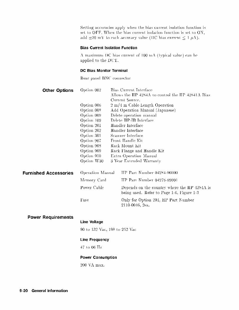
Setting accuracies apply when the bias current isolation function isset to OFF. When the bias current isolation function is set to ON,add �20 mV to each accuracy value (DC bias current � 1 �A).
Bias Current Isolation Function
A maximum DC bias current of 100 mA (typical value) can beapplied to the DUT.
DC Bias Monitor Terminal
Rear panel BNC connector
Other Options Option 002 Bias Current InterfaceAllows the HP 4284A to control the HP 42841A BiasCurrent Source.
Option 006 2 m/4 m Cable Length OperationOption 008 Add Operation Manual (Japanese)Option 009 Delete operation manualOption 109 Delete HP-IB InterfaceOption 201 Handler InterfaceOption 202 Handler InterfaceOption 301 Scanner InterfaceOption 907 Front Handle KitOption 908 Rack Mount KitOption 909 Rack Flange and Handle KitOption 910 Extra Operation ManualOption W30 3 Year Extended Warranty
Furnished Accessories Operation Manual HP Part Number 04284-90000
Memory Card HP Part Number 04278-89001
Power Cable Depends on the country where the HP 4284A isbeing used. Refer to Page 1-6, Figure 1-3
Fuse Only for Option 201, HP Part Number2110-0046, 2ea.
Power RequirementsLine Voltage
90 to 132 Vac, 198 to 252 Vac
Line Frequency
47 to 66 Hz
Power Consumption
200 VA max.
9-20 General Information

Operating EnvironmentTemperature
0�C to 55�C
Humidity
� 95% R.H. at 40�C
Altitude
0m to 2000m
Dimensions 426(W) by 177(H) by 498(D) (mm)
Weight Approximately 15 kg (33 lb., standard)
Display LCD dot-matrix display.
Capable of Displaying
Measured valuesControl settingsComparator limits and decisionsList sweep tablesSelf test message and annunciations
Number of Display Digits
6-digits, maximum display count 999999
SupplementalPerformanceCharacteristics
The HP 4284A supplemental performance characteristics are listedstarting from page 9-26. Supplemental performance characteristicsare not speci�cations but are typical characteristics included assupplemental information for the operator.
Stability MEDIUM integration time and operating temperature at 23�C �5�C]
jZj, jYj, L, C, R < 0.01% / day
D < 0.0001 / day
General Information 9-21

Temperature Coefficient MEDIUM integration time and operating temperature at 23�C �5�C
Test Signal Level jZj, jYj, L, C, R D
� 20 mVrms < 0.0025%/�C < 0.000025/�C
< 20 mVrms < 0.0075%/�C < 0.000075/�C
Settling TimeFrequency (fm)
< 70 ms (fm � 1 kHz)< 120 ms (100 Hz � fm < 1 kHz)< 160 ms (fm < 100 Hz)
Test Signal Level
< 120 ms
Measurement Range
< 50 ms/range shift (fm � 1 kHz)
Input Protection Internal circuit protection, when a charged capacitor is connected tothe UNKNOWN terminals.
The maximum capacitor voltage is:
Vmax =
r1
C[V ]
Where, Vmax � 200 V,C is in Farads.
Figure 9-7. Maximum Capacitance Voltage
9-22 General Information

Measurement Time Typical measurement times from the trigger to the output of EOM atthe Handler Interface. (EOM: End of Measurement)
Integ.
Time
Test Frequency
100 Hz 1 kHz 10 kHz 1 MHz
SHORT 270 ms 40 ms 30 ms 30 ms
MEDIUM 400 ms 190 ms 180 ms 180 ms
LONG 1040 ms 830 ms 820 ms 820 ms
Display Time
Display time for each display format is given as
MEAS DISPLAY page approx. 8 msBIN No. DISPLAY page approx. 5 msBIN COUNT DISPLAY page approx. 0.5 ms
HP-IB Data Output Time
Internal HP-IB data processing time from EOM output tomeasurement data output on HP-IB lines (excluding display time).
Approx. 10 ms
General Information 9-23

DC Bias (1.5 V/2 V) Output Current: 20 mA max.
Option 001 (PowerAmp/DC Bias) DC Bias Voltage
DC Bias voltage applied to DUT (Vdut) is given as,
Vdut = Vb � 100� Ib [V ]
Where, Vb is DC bias setting voltage [V],Ib is DC bias current [A].
DC Bias Current
DC bias current applied to DUT (Idut) is given as,
Idut =Vb
100 + Rdc
[A]
Where, Vb is DC bias setting voltage [V],Rdc is the DUT's DC resistance [].
Maximum DC bias current when the normal measurement can beperformed is as follows.
Measurement
Range
10 100 300 1 k 3 k 10 k 30 k 100 k
Bias Current
IsolationOn 100 mA
O� 2 mA 2 mA 2 mA 1 mA 300 �A 100 �A 30 �A 10 �A
Relative Measurement Accuracy with Bias Current Isolation
When the bias current isolation function is set to ON, add thedisplay uctuation (N) given in the following equation to the Aeof relative measurement accuracy (Refer to \relative measurementaccuracy" of speci�cation).
The following equation is speci�ed when all of the followingconditions are satis�ed.
DUT impedance � 100 Test signal level setting � 1 Vrms
DC bias current � 1 mAIntegration time : MEDIUM
N = P�DUTimpedance []
Measurement Range []�
DCbias current [mA]
Test signal level [Vrms]�
1pn� 10�4 [%]
Where, P is the coe�cient listed on Table A,n is the number of averaging.
9-24 General Information

When the DC bias current is less than 1 mA, apply N value at 1 mA.When integration time is set to SHORT, multiply N value by 5.When integration time is set to LONG, multiply N value by 0.5.
Table 9-7.
Coefficient Related to Test Frequency and Measurement
Range
Meas.
Range
Test Frequency fm [Hz]
20�fm<100 100�fm<1 k 1 k�fm<10 k 10 k�fm�1 M100 0.75 0.225 0.045 0.015
300 2.5 0.75 0.15 0.05
1 k 7.5 2.25 0.45 0.15
3 k 25 7.5 1.5 0.5
10 k 75 22.5 4.5 1.5
30 k 250 75 15 5
100 k 750 225 45 15
Calculation ExampleMeasurement Conditions
DUT : 100 pFTest signal level : 20 mVrms
Test frequency : 10 kHzIntegration time : MEDIUM
Then, DUT's impedance = 1/(2��104�100�10-12) = 159 kMeasurement range is 100 kDC bias current << 1 mAP = 15 (according to Table A)
Ae of relative measurement accuracy without bias currentisolation is �0.22 [%]. (Refer to \relative measurementaccuracy" of speci�cation.)
Then, N = 15�(159�103)/(100�103)�1/(20�10-3)�10-4
= 0.12 [%]
Therefore, Relative Capacitance measurement accuracy is:
�(0.22+0.12) = �0.34 [%]
General Information 9-25

DC Bias Settling Time When DC bias is set to ON, add the settling time listed in thefollowing table to the measurement time. This settling time does notinclude the DUT charge time.
Test
Frequency (fm)
Bias Current Isolation
ON OFF
20 Hz � fm < 1 kHz 210 ms
1 kHz � fm < 10 kHz 70 ms 20 ms
10 kHz � fm � 1 MHz 30 ms
Sum of DC bias settling time plus DUT (capacitor) charge time isshown in the following �gure.
Bias
Source
Bias Current
Isolation
Test Frequency (fm)
1 Standard On/O� 20 Hz � fm � 1 MHz
2 Option 001 O� 20 Hz � fm � 1 MHz
3 On 10 kHz � fm � 1 MHz
4 1 kHz � fm < 10 kHz
5 20 Hz � fm < 1 kHz
Figure 9-8. Measurement Time
9-26 General Information

Rack/HandleInstallation
The HP 4284A can be rack mounted and used as a component of ameasurement system. Following �gure shows how to rack mount theHP 4284A.
Table 9-8. Rack Mount Kits
Option Description Kit Part Number
907 Handle Kit HP Part Number 5061-9690
908 Rack Flange Kit HP Part Number 5061-9678
909 Rack Flange & Handle Kit HP Part Number 5061-9684
Figure 9-9. Rack Mount Kits Installation
1. Remove the adhesive-backed trim strips 1 from the left and rightfront sides of the HP 4284A.
2. HANDLE INSTALLATION: Attach the front handles 3 to thesides using the screws provided and attach the trim strip 4 to thehandle.
3. RACK MOUNTING: Attach the rack mount ange 2 to the leftand right front sides of the HP 4284A using the screws provided.
4. HANDLE AND RACK MOUNTING: Attach the front handle 3 and the rack mount ange 5 together on the left and right frontsides of the HP 4284A using the screws provided.
General Information 9-27

5. When rack mounting the HP 4284A (3 and 4 above), remove allfour feet (lift bar on the inner side of the foot, and slide the foottoward the bar).
Storage andRepacking
This paragraph describes the environment for storing or shipping theHP 4284A, and how to repackage the HP 4284A for shipment whennecessary.
Environment The HP 4284A should be stored in a clean, dry environment. Thefollowing environmental limitations apply for both storage andshipment.
Temperature: �20�C to 60�CHumidity: � 95% RH (at 40�C)
To prevent condensation from taking place on the inside of theHP 4284A, protect the instrument against temperature extremes.
Original Packaging Containers and packing materials identical to those used in factorypackaging are available through your closest Hewlett-Packard saleso�ce. If the instrument is being returned to Hewlett-Packard forservicing, attach a tag indicating the service required, the returnaddress, the model number, and the full serial number. Markthe container FRAGILE to help ensure careful handling. In anycorrespondence, refer to the instrument by model number and its fullserial number.
Other Packaging The following general instructions should be used when repackingwith commercially available materials:
1. Wrap the HP 4284A in heavy paper or plastic. When shippingto a Hewlett-Packard sales o�ce or service center, attach a tagindicating the service required, return address, model number, andthe full serial number.
2. Use a strong shipping container. A double-walled carton made ofat least 350 pound test material is adequate.
3. Use enough shock absorbing material (3 to 4 inch layer) around allsides of the instrument to provide a �rm cushion and to preventmovement inside the container. Use cardboard to protect the frontpanel.
4. Securely seal the shipping container.
5. Mark the shipping container FRAGILE to help ensure carefulhandling.
6. In any correspondence, refer to the HP 4284A by model numberand by its full serial number.
9-28 General Information

Caution The memory card should be removed, before packing the HP 4284A.
General Information 9-29


10
Performance Tests
Introduction This chapter provides the test procedures to verify that theHP 4284A meets the speci�cations listed in Chapter 9. All tests canbe performed without accessing the indicator of the instruments.Performance tests are used to perform incoming inspection and toverify that the HP 4284A is within its performance speci�cationafter troubleshooting or adjustment have been performed. Ifthe performance tests indicate that the HP 4284A is not withinspeci�cations, check your test setup, then proceed to Adjustment orTroubleshooting as required.
Note Allow the HP 4284A to warm up a minimum of 30 minutes beforestarting any of the performance tests.
Note The performance tests are valid only when performed in an ambienttemperature of 23 �C �5 �C.
Test Equipment Table 10-1 lists the test equipment required to perform the testsdescribed in this chapter. Use only calibrated test instruments whenperformance testing the HP 4284A. If the recommended equipmentwith speci�cations equal to or surpassing those of the recommendedequipment may be used.
Note Components used as standards must be (1) calibrated using aninstrument whose speci�cations are traceable to the National Bureauof Standard (NBS) or an equivalent standards group, or (2) calibrateddirectly by an authorized calibration organization, such as NBS.The calibration cycle depends on the stability speci�cation of eachcomponent.
Performance Tests 10-1

Performance TestRecord
Record the results of each performance test in the Performance Test Record located at the end of this chapter. The performancerecord lists each test, parameters tested, and acceptable tolerancelimits. Keep a record of past performance test results for comparisonpurposes to help indicate any possible areas of developing trouble.
Note The test limits indicated in each performance test do not take intoaccount the measurement errors induced by the st equipment used.Be sure to consider this when determining whether or not theHP 4284A meets is indicated speci�cations.
Calibration Cycle The HP 4284A required periodic performance veri�cation. How oftenyou verify performance depends on the operating and enviorementalconditions. Check the HP 4284A using the performance testsdescribed in this chapter at least once a year. To minimizeinstrument down-time and to ensure optimum operation, performpreventive maintenance and calibration at least twice a year.
10-2 Performance Tests

Table 10-1. Recommended Test Equipment
Equipment Requirements Recommmended Model
Electronic Counter Frequency: 20 Hz to 1 MHz HP 5334B
Accuracy: <<0.01%
RMS Voltmeter Frequency: 20 Hz to 1 MHz HP 3458A
Voltage Range: 5 mVrms to 20 Vrms
Accuracy: <<3.0%
DC Voltmeter Voltage range: �40 V to 40 V HP 3458A
Accuracy: <<0.1%
Standard Capacitor No substitute HP16380A
HP 16380C
Standard Resister No Substitute HP 16074A
DC Power Source +5 V, 0.1 A HP 6214C
Adapter BNC(f) to BNC(f) HP PN 1250-0080
Tee, BNC(m)(f)(f) HP PN 1250-0781
BNC(f) to Dual Banana HP PN 1251-2277
Cable BNC(m)-to-BNC(m), 30 cm HP PN 8120-1838
Test Leads 2 BNC(m) to 3 alligator clips HP PN 8120-1661
4 BNC(m), Cable Length 1 m HP 16048A
4 BNC(m), Cable Length 2 m HP 16048D
4 BNC(m), Cable Length 4 m HP 16048E
HP-IB Cable HP-IB cable, 1 m HP 10388A
Computer HP Technical Computer HP 9000 Series 200 Model 226
Memory Card (furnished accessory) HP PN 04278-89001
Bias IF Simulator No substitute HP PN 42841-65001
Handler Simulator No substitute HP PN 04278-65001
Scanner Simulator No substitute HP PN 04278-65301
Simulator Cable No substitute HP PN 04278-61635
Bias IF Cable GP-IO Cable HP PN 42841-61640
Performance Tests 10-3

System Reset By using SYSTEM RESET function the HP 4284A can be set easilyfor the performance test. SYSTEM RESET can be performed usingthe following procedure.
Procedure 1. Press �MEAS SETUP� to display MEAS SETUP page.
2. Use CURSOR keys to move the cursor to the SYS MENU �eld.
3. PressNNNNNNNNNNNNNNNNNNNNNNNNNNmore 1/2 softkey to display
NNNNNNNNNNNNNNNNNNNNNNNNNNNNNNNNNNNNNNSYSTEM RESET .
4. PressNNNNNNNNNNNNNNNNNNNNNNNNNNNNNNNNNNNNNNSYSTEM RESET .
5. PressNNNNNNNNNNNYES to perform a SYSTEM RESET.
10-4 Performance Tests

Test FrequencyAccuracy Test
This test veri�es that the accuracy of the HP 4284A's test frequencyis within �0.01%.
Figure 10-1. Test Frequency Accuracy Test Setup
Equipment Electronic Counter HP 5334BBNC(m)-to-BNC(m) Cable, 30 cm HP PN 8120-1838
Procedure: 1. Set up the equipment as shown in Figure 10-1.
2. Perform a SYSTEM RESET as described in \System Reset".
3. Set the Test Frequency in accordance with Table 10-2, andcon�rm that the counter readings are within the test limits givenin the table.
Table 10-2. Test Frequency Test limits
Test Frequency Test Limits
1 kHz 0.9999 kHz to 1.0001 kHz
8 kHz 7.9992 kHz to 8.0008 kHz
20 kHz 19.998 kHz to 20.002 kHz
80 kHz 79.992 kHz to 80.008 kHz
400 kHz 399.96 kHz to 400.04 kHz
1 MHz 0.9999 MHz to 1.0001 MHz
Performance Tests 10-5

Test SignalLevel/Level-MonitorAccuracy Test
This test veri�es the HP 4284A's test signal level, and test signallevel monitor accuracy.
Figure 10-2. Test Signal Level Accuracy Test Setup Using an Interface Box
Figure 10-3. Test Signal Level Accuracy Test Setup Without an Interface Box
Note The BNC to BNC cables used in this test should be shorter than 30cm.
Equipment: Interface Box HP PN 04284-65007Multimeter HP 3458ACable BNC(m)-to-BNC(m) 30 cm HP PN 8120-1838BNC(f) to dual banana plug Adapter HP PN 1251-2277
10-6 Performance Tests

Procedure: 1. Set up the equipment as shown in Figure 10-2.
Note If the Interface Box is not available, use the following cables andadapters as a substitute. Figure 10-3 shows the test setup withoutthe interface box.
BNC(m) to BNC(m) Cable, 30 cm HP PN 8120-1838 2ea.Tee, BNC(m)(f)(f) Adapter HP PN 1250-0781
2. Set the multimeter to ACV.
3. Perform a SYSTEM RESET as described in \System Reset".
4. Set HP 4284A's controls as follows:
Test Frequency: 1.25 kHzHigh Power Option: OFF
5. Display the MEAS DISPLAY page.
6. Set the Oscillator Level in accordance with Table 10-3, andcon�rm that the Multimeter reading and the Level Monitorreading are within the test limits given in the table.
7. Set the Test Frequency to 960 kHz and perform step 6.
Note Steps 8 through 11 should be performed only when the HP 4284A isequipped with Option 001.
8. Set the controls of the HP 4284A as follows:
Test Frequency: 1.25 kHzHigh Power Option: ON
9. Display the MEAS DISPLAY page.
10. Set the Oscillator Level in accordance with Table 10-4, andcon�rm that the Multimeter reading and the Level Monitorreading are with in the test limits given in Table 10-3.
11. Set the Test Frequency to 960 kHz and perform step 10.
Performance Tests 10-7

Table 10-3.
Test Signal Level/Level-Monitor Test Limits (Hi-PW OFF)
Test Signal
Level
Test Limits
Multimeter Reading Level Monitor Reading
5 mV 5 mV �1.5 mV M.R. �(3%+0.5 mV)10 mV 10 mV �2 mV M.R. �(3%+0.5 mV)20 mV 20 mV �3 mV M.R. �(3%+0.5 mV)50 mV 50 mV �6 mV M.R. �(3%+0.5 mV)100 mV 100 mV �11 mV M.R. �(3%+0.5 mV)200 mV 200 mV �21 mV M.R. �(3%+0.5 mV)250 mV 250 mV �26 mV M.R. �(3%+0.5 mV)500 mV 500 mV �51 mV M.R. �(3%+0.5 mV)1 V 1 V �101 mV M.R. �(3%+0.5 mV)2 V 2 V �201 mV M.R. �(3%+0.5 mV)
M.R. is the Multimeter Reading for the HP 4284A's output signallevel.
Table 10-4.
Test Signal Level/Level-Monitor Test Limits (Hi-PW ON)
Test Signal
Level
Test Limits
Multimeter Reading Level Monitor Reading
10 mV 10 mV �2 mV M.R. �(3%+0.5 mV)1 V 1 V �0.11 V M.R. �(3%+0.5 mV)2.5 V 2.5 V �0.26 V M.R. �(3%+5 mV)20 V 20 V �2.01 V M.R. �(3%+5 mV)
M.R. is the Multimeter Reading for the HP 4284A's output signallevel.
10-8 Performance Tests

DC Bias LevelAccuracy Test
This test veri�es the accuracy of the HP 4284A's internal dc biaslevel.
Figure 10-4. DC Bias Level Accuracy Test Setup Using an Interface Box
Figure 10-5. DC Bias Level Accuracy Test Setup Without an Interface Box
Equipment: Interface Box HP PN 04284-65007Multimeter HP 3458ACable BNC(m)-to-BNC(m) 30 cm HP PN 8120-1838BNC(f) to dual banana plug Adapter HP PN 1251-2277
Performance Tests 10-9

Procedure: 1. Connect the equipment as shown in Figure 10-4.
Note if the Interface Box is not available, use the following cables andadapters as a substitute. Figure 10-5 shows the test setup withoutthe interface box. The center conductors of HCUR and HPOT areconnected to the Hi-input of the multimeter. The center conductorsof the LCUR and LPOT are connected to Lo-input of the multimeter.
Cable BNC(m)-to-BNC(m) 30 cm HP PN 8120-1838 2 ea.Test Lead 2 BNCs(m) to HP PN 8120-16613 alligator clipsTee, BNC(m)(f)(f) Adapter HP PN 1250-0781 2 ea.
2. Set the multimeter to DCV.
3. Perform a SYSTEM RESET as described in \System Reset".
4. Set HP 4284A's controls as follows:
Test Signal level: 0 mVHigh Power Option: OFFDC Bias: ON
Note The High Power Mode cannot be changed when the DC Bias is set toON.
Set the DC Bias voltage in accordance with Table 10-5, andcon�rm that the Multimeter readings are within the test limitsgiven in Table 10-5.
Table 10-5. DC Bias Level Test Limits (Hi-PW OFF)
Bias Level Test Limits
1.5 V 1.425 V to 1.575 V
2 V 1.9 V to 2.1 V
Note Steps 6 through 7 should be performed only when the HP 4284A isequipped with Option 001.
5. set the HP 4284A's controls as follows:
Test Signal Level: 0 mVHigh Power Option: ONDC Bias: ON
6. Set the DC Bias Level in accordance with Table 10-6, and con�rmthat the Multimeter readings are within the test limits given inTable 10-6.
10-10 Performance Tests

Table 10-6. DC Bias Level Test Limits (Hi-PW ON)
Bias Level Test Limits
0 V 0.0010 V to �0.0010 V0.1 V 0.0989 V to 0.1011 V
2 V 1.9970 V to 2.0030 V
6 V 5.9920 V to 6.0080 V
14 V 13.981 V to 14.019 V
30 V 29.960 V to 30.040 V
40 V 39.950 V to 40.050 V
�0.1 V �0.1011 V to �0.0989 V�2 V �2.0030 V to �1.9970 V�6 V �6.0080 V to �5.9920 V�14 V �14.019 V to �13.981 V�30 V �30.040 V to �29.960 V�40 V �40.050 V to �39.950 V
Performance Tests 10-11
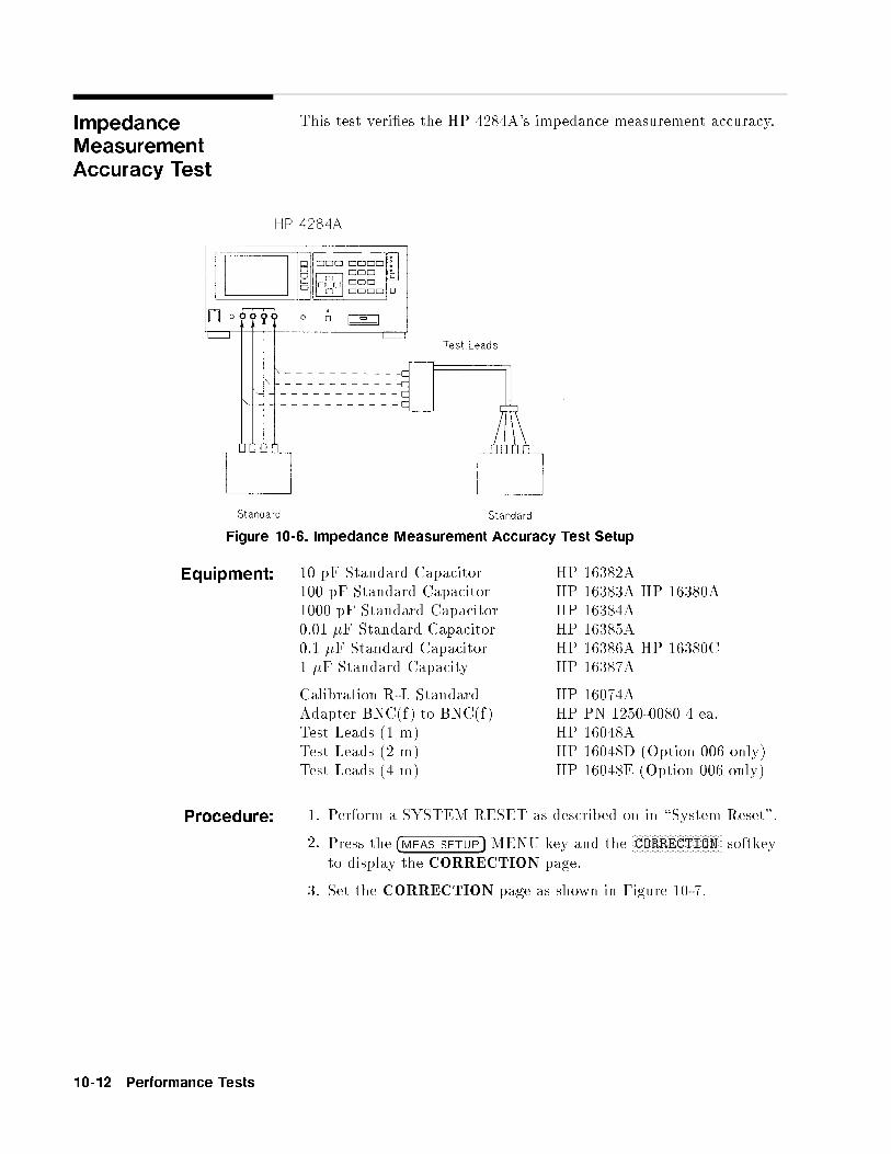
ImpedanceMeasurementAccuracy Test
This test veri�es the HP 4284A's impedance measurement accuracy.
Figure 10-6. Impedance Measurement Accuracy Test Setup
Equipment: 10 pF Standard Capacitor HP 16382A100 pF Standard Capacitor HP 16383A HP 16380A1000 pF Standard Capacitor HP 16384A0.01 �F Standard Capacitor HP 16385A0.1 �F Standard Capacitor HP 16386A HP 16380C1 �F Standard Capacity HP 16387A
Calibration R-L Standard HP 16074AAdapter BNC(f) to BNC(f) HP PN 1250-0080 4 ea.Test Leads (1 m) HP 16048ATest Leads (2 m) HP 16048D (Option 006 only)Test Leads (4 m) HP 16048E (Option 006 only)
Procedure: 1. Perform a SYSTEM RESET as described on in \System Reset".
2. Press the �MEAS SETUP� MENU key and theNNNNNNNNNNNNNNNNNNNNNNNNNNNNNNNNCORRECTION softkey
to display the CORRECTION page.
3. Set the CORRECTION page as shown in Figure 10-7.
10-12 Performance Tests

Figure 10-7. Correction Page Setup
Note It takes approx. 90 s each to store the OPEN CORRECTION dataand the SHORT CORRECTION data.
4. Connect the OPEN termination to the HP 4284A's UNKNOWN
terminals.
5. Move the cursor to the OPEN �eld.
6. Press theNNNNNNNNNNNNNNNNNNNNNNNNNNNNNMEAS OPEN softkey to store the open correction data.
7. Connect the SHORT termination to the HP 4284A'sUNKNOWN terminals.
8. Move the cursor to the SHORT �eld.
9. Press theNNNNNNNNNNNNNNNNNNNNNNNNNNNNNNNNMEAS SHORT softkey to store the short correction data.
10. Set the HP 4284A to the Manual Trigger mode.
11. Perform Steps 12 through 14 for the all standards and settingslisted in Table 10-7.
Note Test signal level is set to 5.1 V only when the HP 4284A is equippedwith Option 001
12. Connect the Standard to the HP 4284A's UNKNOWN terminals.
13. Press the �TRIGER� key.
14. Con�rm that the HP 4284A's reading is within the test limits inTable 10-7.
Performance Tests 10-13

Table 10-7. Impedance Measurement Accuracy Test Limits (1 of 2)
Setting Test Limits (Cp, D)
Signal
Level
Test
Frequency
10 pF Standard 100 pF Standard 1000 pF Standard
510 mV 20 Hz Cp C.V. �32.09 pFD �0.00319
125 Hz Cp C.V. �1.759 pF C.V. �3.05 pFD �0.01739 �0.00286
1 kHz Cp C.V. �0.312 pF C.V. �1.00 pFD �0.00293 �0.00081
12.5 kHz Cp C.V. �0.0318 pF C.V. �0.137 pF C.V. �1.13 pFD �0.0031 �0.00130 �0.00095
48 kHz Cp C.V. �0.0246 pF C.V. �0.162 pF C.V. �1.16 pFD �0.0028 �0.0190 �0.00103
96 kHz Cp C.V. �0.0275 pF C.V. �0.122 pF C.V. �1.31pFD �0.0035 �0.00116 �0.00111
1 MHz Cp C.V. �0.0249 pF C.V. �0.102 pF C.V.1 �1.53 pFD �0.0038 �0.00082 �0.00083
20 mV 1 kHz Cp C.V. �0.898 pF C.V. �2.53 pF1 MHz Cp C.V. �0.0402 pF C.V. �0.208 pF C.V.1 �2.59 pF
5.1 V* 1 kHz Cp C.V. �0.293 pF C.V. �1.48 pF1 MHz Cp C.V. �0.0297 pF C.V. �0.152 pF C.V.1 �2.03 pF
C.V.: Standard's calibration value at 1 kHz.C.V.1: C.V. multiplied by 1.0003
*Option 001 only
10-14 Performance Tests

Table 10-7. Impedance Measurement Accuracy Test Limits (2 of 2)
Setting Test Limits (Cp)
Signal
Level
Test
Frequency
0.01 �F Standard 0.1 �F Standard 1 �F Standard
510 mV
1 kHz C.V. �0.0082 nF C.V. �0.081 nF C.V. �0.81 nF20 mV
1 kHz C.V. �0.0188 nF C.V. �0.182 nF C.V. �1.87 nF5.1 V*
1 kHz C.V. �0.0132 nF C.V. �0.131 nF C.V. �1.31 nF
C.V.: Standard's calibration value at 1 kHz.C.V.1: C.V. multiplied by 1.0005C.V.2: C.V. multiplied by 1.0002
*Option 001 only
15. Set the measurement function to R-X.
16. Perform Steps 17 through 19 for all the standards and settingslisted in Table 10-8.
17. Connect the Standard to the HP 4284A's UNKNOWN terminals.
18. Press the �TRIGGER� key.
19. Con�rm that the HP 4284A's readings are within the test limitslisted in Table 10-8.
Performance Tests 10-15

Table 10-8.
Impedance Measurement Accuracy Test Limits
Setting Test Limits (R)
Signal
Level
Test
Frequency
100 Standard 1 k Standard*
510 mV 20 Hz C.V. �0.285 C.V. �2.81 125 Hz C.V. �0.112 C.V. �1.11 1 kHz C.V. �0.082 C.V. �0.81
12.5 kHz C.V. �0.132 C.V. �1.31 48 kHz C.V. �O.132 C.V. �1.31 96 kHz C.V. �0.132 C.V. �1.31 1 MHz C.V. �0.154 C.V. �1.02
20 mV 20 Hz C.V. �0.691 C.V. �6.60 1 kHz C.V. �O.191 C.V. �1.82 1 MHz C.V. �0.264 C.V. �2.06
5.1 V** 20 Hz C.V. *0.284 C.V. �2.811 kHz C.V. �O.131 C.V. �1.31 1 MHz C.V. �0.204 C.V. �1.52
C.V.: Standard's calibration value at DC.
*1 k standard should be measured on the 300 range.**Option 001 only
20. Connect the 1 m Test Leads (HP 16048A) to the UNKNOWN
terminals.
21. Press the �MEAS SETUP� MENU key and theNNNNNNNNNNNNNNNNNNNNNNNNNNNNNNNNCORRECTION softkey
to display the CORRECTION page.
22. Set the CABLE length selection switch to 1 m.
23. Store the OPEN CORRECTION data and the SHORTCORRECTION data referring to Steps 4 through 9. In thisprocedure the OPEN termination and the SHORT terminationshould be connected to the 1 m Test Leads (HP 16048A).
24. Set the HP 4284A to the manual trigger mode.
25. Set the measurement function to Cp-D.
26. Connect the 1000 pF standard to the 1 m Test Leads (HP16048A)
27. Perform Step 28 through 29 for all the test frequencies listed inTable 10-9.
10-16 Performance Tests

28. Press the �TRIGGER� key.
29. Con�rm that HP 4284A's reading is within the test limits inTable 10-9.
Table 10-9.
Impedance Measurement Accuracy Test Limits for 1
m Cable Length Operation
Setting Test Limits (Cp)
Signal Level Test Frequency
510 mV 20 Hz C.V. �32.10 pF125 Hz C.V. �3.06 pF1 kHz C.V. �1 00 pF
12.5 kHz C.V. �1.14 pF48 kHz C.V. �1.17 pF96 kHz C.V. �1.32 pF1 MHz C.V.1 �1.66 pF
20 mV 1 kHz C.V. �2.54 pF1 MHz C.V.1 �2.72 pF
5.1 V* 20 Hz C.V. �28.94 pF1 kHz C.V. �1.50 pF1 MHz C.V.1 �2.47 pF
C.V.: Standard's calibration value at DC.C.V.1: C.V. multiplied by 1.0003
*Option 001 only
Note Steps 30 through 49 should be performed only when the HP 4284A isequipped with Option 006.
Performance Tests 10-17

30. Connect the 2 m Test Leads (HP 16048D) to the UNKNOWN
terminals.
31. Press the �MEAS SETUP� MENU key and theNNNNNNNNNNNNNNNNNNNNNNNNNNNNNNNNCORRECTION softkey
to display the CORRECTION page.
32. Set the CABLE to 2 m.
33. Store the OPEN CORRECTION data and the SHORTCORRECTION data referring to Step 4 through 9. In thisprocedure the OPEN termination and the SHORT terminationshould be connected to the 2 m Test Leads (HP 16048D).
34. Set the HP 4284A to the Manual Trigger mode.
35. Set the measurement function to Cp-D.
36. Connect the 1000 pF standard to the 2 m Test Leads (HP16048D).
37. Perform Steps 38 through 39 for all the test frequencies listed inTable 10-10.
38. Press the �TRIGGER� key.
39. Con�rm that the HP 4284A's reading is within the test limits inTable 10-10.
40. Connect the 4 m Test Leads (HP 16048E) to theUNKNOWNterminals.
41. Press the �MEAS SETUP� MENU key and theNNNNNNNNNNNNNNNNNNNNNNNNNNNNNNNNCORRECTION softkey
to display the CORRECTION page.
42. Set the CABLE to 4 m.
43. Store the OPEN CORRECTION data and the SHORTCORRECTION data referring to steps 4 through 9. In thisprocedure the OPEN termination and the SHORT terminationshould be connected to the 4 m Test Leads (HP 16048E).
44. Set the HP 4284A to the Manual Trigger mode.
45. Set the measurement function to Cp-D.
46. Connect the 1000 pF standard to the 4 m Test Leads (HP16048E).
47. Perform Steps 48 through 49 for all the test frequencies listed inTable 10-10.
48. Press the �TRIGGER� key.
49. Con�rm that the HP 4284A's reading is within the test limitslisted in Table 10-10.
10-18 Performance Tests

Table 10-10.
Impedance Measurement Accuracy Test Limits for 2 m
and 4 m Cable Length Operation
Setting Test Limits (Cp)
Signal
Level
Test
Frequency
2 m Cable 4 m Cable
510 mV 20 Hz C.V. �32.10 pF C.V. �32.11 pF125 Hz C.V. �3.06 pF C.V. �3.07 pF1 kHz C.V. �1.00 pF C.V. �1.01 pF
12.5 kHz C.V. �1.14 pF C.V. �1.15 pF48 kHz C.V. �1.18 pF C.V. �1 19 pF96 kHz C.V. �1.34 pF C.V. �1.37 pF1 MHz C.V.1 �1.80 pF C.V.1 �2.06 pF
20 mV 1 kHz C.V. �2.54 pF C.V. �2.56 pF1 MHz C.V.1 �2.90 pF C.V.1 �3.20 pF
5.1 V* 20 Hz C.V. �28.97 pF C.V. �29.02 pF1 kHz C.V. �1.53 pF C.V. �1.58 pF1 MHz C.V.1 �2.92 pF C.V.1 �3.81 pF
C.V.: Standard's calibration value at DC.C.V.1 : C.V. multiplied by 1.0003
* Option 001 only
Performance Tests 10-19

Store and LoadFunction Test
This test veri�es the HP 4284A's ability to store information to, andload information from a memory card.
Equipment: Memory Card HP PN 04278-89001
Procedure: 1. Perform a SYSTEM RESET as described in \System Reset".
2. Insert a memory card into the MEMORY card slot.
3. Display the MEAS SETUP page.
Note This test should be performed from the MEAS SETUP page.
4. Change the measurement function from Cp-D to Cp-G in theFUNC �eld.
5. Use the CURSOR arrow keys to move the cursor to the SYSMENU �eld.
6. Press theNNNNNNNNNNNNNNNNNSTORE softkey to store the HP 4284A's control settings
to the memory card as data record-number 10.
7. Press theNNNNNNNNNNNNNNNNNNNNNNNNNNNNNNNNNNNCLEAR SETUP softkey to clear the set up, and then
con�rm that FUNC is set to Cp-D.
8. Press theNNNNNNNNNNNNNNLOAD softkey to load data record-number 10 from the
memory card.
9. Con�rm that the measurement function is set to Cp-G.
10-20 Performance Tests

HP-IB Interface Test This test veri�es the HP 4284A'S HP-IB function.
Figure 10-8. HP-IB Interface Test Setup
Equipment: Personal Technical Computer HP 9000 Series 200 Model 226HP-IB Cable HP 10833A
Procedure: 1. Set the HP 4284A's HP-IB address to 17.
2. Set up the equipment as shown in Figure 10-8. Use thecomputer's interface Select Code (7).
3. Load BASIC and input the following program, but do not RUNthe program yet.
10 DIM A$[38]
20 OUTPUT 717;"*IDN?"
30 ENTER 717;A$
40 PRINT AS
50 OUTPUT 717;"*SRE328"
60 OUTPUT 717;"ABC"
70 PRINT SPOLL(717)
80 END
4. Press the computer's STEP key three times to single step to line20.
5. Con�rm that the LTN and RMT lamps are ON and that thesoftkey label page cannot be changed by pressing the MENU
keys.
6. Press the LCL key on the HP 4284A.
7. Con�rm that the LTN lamp stays ON, the RMT lamp is OFF,and the softkey label page can be changed by pressing theMENU keys.
8. Press the computer's STEP key to execute line 30 and con�rmthat the TLK lamp is ON.
9. Step to line 40 and con�rm that the following message isdisplayed on the computer.
"HEWLETT-PACKARD,4284A,0,REV01.01 "
Performance Tests 10-21

10. Step to line 60, and con�rm that the SRQ, LTN, and RMT
lamps are ON.
11. Step to line 80 and con�rm that the status byte value displayedon the computer is greater than 95.
10-22 Performance Tests

Bias CurrentInterface FunctionTest (Option 002only)
This test veri�es the bias current interface functions.
Equipment: Bias Interface Simulator HP PN 42841-65001Bias Interface Cable HP PN 42841-61640DC Power Supply HP 6214C
Procedure: 1. Set all switches of S1 and S2 on the bias interface simulator to '1'as shown in Figure 10-9.
Figure 10-9. Bias Interface Simulator
2. Set DC power supply output voltage +5 V. Connect TP2(GND)on the bias interface simulator to '�' terminal of the powersupply. Then connect TP1(Vcc) on the simulator to '+' terminalof the power supply. (refer to Figure 10-9 and Figure 10-10)
Performance Tests 10-23

Note DC power for the bias interface simulator can be supplied from theHP 4284A instead of from an external DC power supply. For furtherdetails, see \Supplying DC Power to the Simulator".
3. Interconnect the bias interface simulator and bias interfaceconnector on the rear panel of the HP 4284A with the biasinterface cable as shown in Figure 10-10.
Figure 10-10. Bias Current Interface Function Test Setup
4. Turn the HP 4284A ON.
5. Press the �CATALOG/SYSTEM� MENU key.
6. Press theNNNNNNNNNNNNNNNNNNNNNNNNNNNNNSELF TEST softkey to display the SELF TEST page.
7. Use the CURSOR arrow keys to move the cursor to the TESTMENU �eld.
8. Press the �7� and the �ENTER� keys to select the Bias Current I/FI/O test.
Note Check the settings of S1 and S2 described in the step 1, if theHP 4284A's LCD displays \E74:Illegal test setup".
9. Con�rm the /RESET LED on the bias interface simulator turnsON.
10. Con�rm CS0 and CS1 LEDs on the simulator turn ON as theHP 4284A's output signal is displayed on the LCD. (Refer toFigure 10-11).
11. Con�rm that ADRS1-ADRS6 LEDs on the simulator turn ONin laccordance with the hexadecimal number displayed on theLCD. One of the 6 LEDs turns ON in sequence as shown inFigure 10-11.
12. Con�rm that DO0-DO7 LEDs on the simulator turn ON inaccordance with the hexadecimal number displayed on theLCD. One of the 8 LEDs turns ON in sequence as shown inFigure 10-11.
10-24 Performance Tests

Figure 10-11. Bias Current Interface Function Test
13. Con�rm that \DI0 TO 7" and \DI8 TO 15" on the LCD of theHP 4284A display hexadecimal number \FF".
14. Set switches S1 and S2 on the bias interface simulator to '0'.Then con�rm that hexadecimal number \00" is displayed by\DI0 TO 7" and \DI8 TO 15".
Note The states of S1(DI0 TO 7) and S2(DI1 TO 8) are displayed as ahexadecimal number on the HP 4284A's LCD.
15. Press theNNNNNNNNNNNNNNNNNNNNNNNNNNTEST END softkey.
Caution Do not execute any SELF TEST except for the Bias Current I/F I/OTest or the HP 4284A will become inoperative.
Performance Tests 10-25

Handler InterfaceFunction Test(Option 201 only)
Perform this test only when troubleshooting the Option 201 HandlerInterface Board.
This test veri�es the handler interface functions.
Equipment: Handler Simulator HP PN 04278-65001
Procedure: 1. Disconnect the power cable from the HP 4284A and allow 1minute for the internal capacitors to discharge.
Warning Dangerous energy/voltage exists when the HP 4284A is in operation,
and for a time after it is powered down. Allow 1 minutes for the
internal capacitors to discharge.
2. Disconnect the two rear feet which lock the top cover and rearpanel together.
3. Fully loosen the top cover retaining screws located on the rear ofthe top cover.
4. Slide the top cover toward rear and lift it o�. The top shieldplate will be visible.
5. Remove the top shield plate to expose the PC boards.
6. Disconnect a at cable from the handler interface board whichhas an ORANGE and a BLACK, or an ORANGE and a REDextractors. See Figure 10-12.
Figure 10-12. Interface Board Locations
7. Remove the handler interface board.
10-26 Performance Tests

Caution The interface board contains electronic components that can bedamaged by static electricity through electrostatic discharge(ESD).To prevent ESD damage,maintain frequent contact with any baresheet metal surface on the chassis. A grounding wrist strap (orsimilar device) is useful for this purpose. Handle the board carefullyat all times. Avoid touching electronic components or circuit paths.
Note Before performing step 8, note the jumper settings in order to returnthem to the same settings at the end of this function test.
8. Set the jumpers on the handler interface board to the samesettings as when the board is shipped from the factory. Con�gurethe interface board according the color of the extractors, seestep (1) for ORANGE and BLACK extractors and step (2) forORANGE and RED extractors.
(1) ORANGE and BLACK (See Figure 10-13.)
OPEN (remove): W1, W2, W3, W5, W6, W8, W9, W10,and R101 thru R121SHORT: W4, W7, and W11
Figure 10-13. Jumper Settings
Performance Tests 10-27

(2) ORANGE and RED (See Figure 10-14.)
SET: All Jumper Switches to position \N"OPEN (remove): R101 thru R121
Figure 10-14. Jumper Settings
9. Replace the handler interface board, top shield plate, rear feet,and the top cover.
10. Turn the HP 4284A ON.
11. Connect the handler interface connector on the HP 4284A's rearpanel to the handler simulator as shown in Figure 10-14.
12. Press the �CATALOG/SYSTEM� MENU key.
13. Press theNNNNNNNNNNNNNNNNNNNNNNNNNNNNNSELF TEST softkey to display the SELF TEST page.
Figure 10-15. Handler Interface Function Test Set UP
10-28 Performance Tests

14. Use the CURSOR arrow keys to move the cursor to the TESTMENU �eld.
15. Press the �4� and the �ENTER� keys to select the Handler I/F test.
16. Press theNNNNNNNNNNNNNNNNNNNNNNNNNNNNNNNNTEST START softkey.
17. Con�rm that the LEDs on the handler simulator turn ON inaccordance with the HP 4284A's output signals displayed onthe LCD. The LEDs turns ON light in the sequence shown inFigure 10-15.
Figure 10-16. Handler Interface Function Check
18. Press theNNNNNNNNNNNNNNNNNNNNNNNNNNTEST END softkey.
Caution Do not execute any SELF TEST except for the Bias Current I/F I/OTest or the HP 4284A will become inoperative. The remaining SELFTEST are for serviceuse only.
19. Return the jumper settings on the handler interface board totheir original settings.
Performance Tests 10-29

Handler InterfaceFunction Test(Option 202 only)
Perform this test only when troubleshooting the Option 202 handlerinterface board.
This test veri�es the Option 202 handler interface functions. Whenthis test is performed the following LEDs WILL NOT turn ONbecause the signals they represent are not used by the Option 202handler interface board.
PHI-, PLO-, SREJ-, UNBAL- and ALARM-
Equipment: Handler Simulator HP PN 04278-65001Cable HP PN 04278-61635
Procedure: 1. Perform steps 1 through 5 described \Procedure:".
2. Disconnect the at cable from the handler interface board. Thehandler interface board has brown and an orange extractors andits location is shown in Figure 10-12.
3. Remove the handler interface board.
Caution The interface board contains electronic components that can bedamaged by static electricity through electrostatic discharge(ESD).To prevent ESD damage,maintain frequent contact with any baresheet metal surface on the chassis. A grounding wrist strap (orsimilar device) is useful for this purpose. Handle the board carefullyat all times. Avoid touching electronic components or circuit paths.
Note Before performing step 4, note the jumper settings in order to returnthem to the same setting at the end of this function test.
4. Set the jumpers on the handler interface board the same settingsas when the board is shipped from the factory referring toFigure 10-16.
10-30 Performance Tests
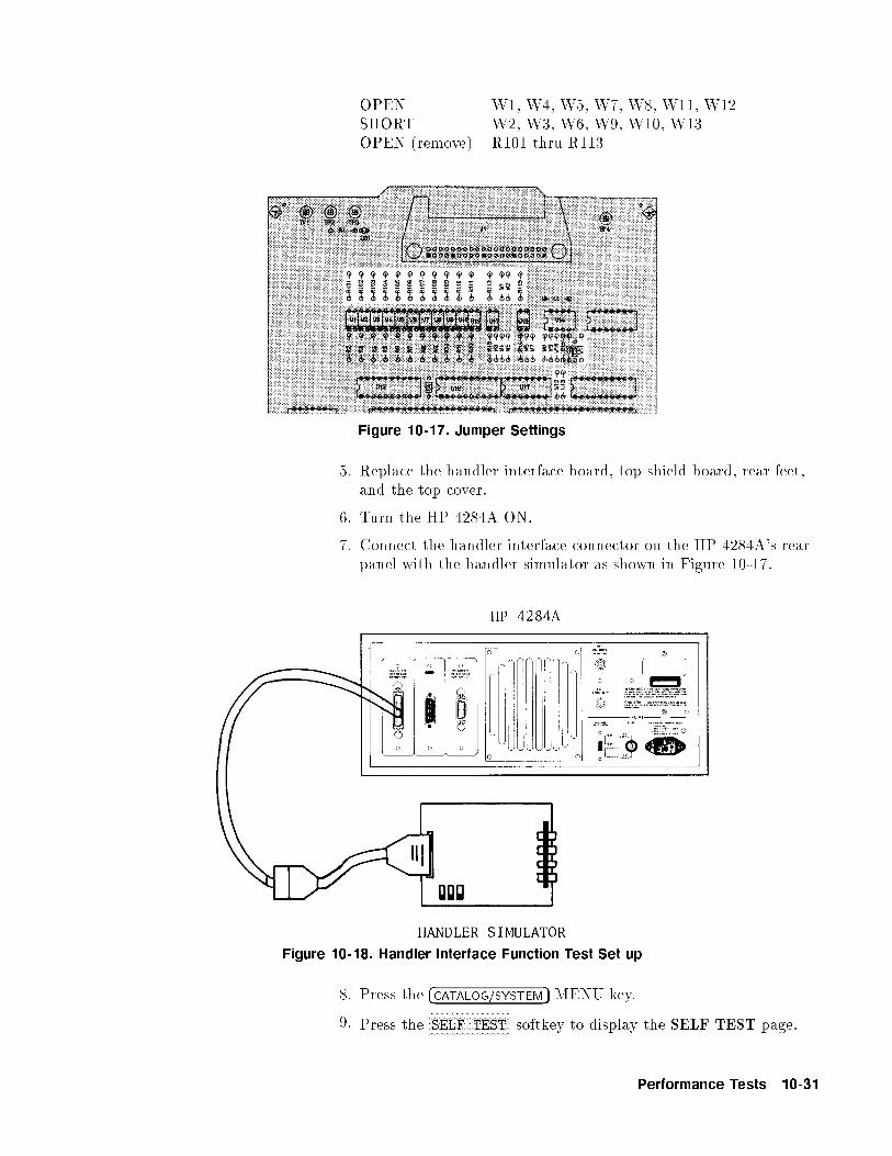
OPEN W1, W4, W5, W7, W8, W11, W12SHORT W2, W3, W6, W9, W10, W13OPEN (remove) R101 thru R113
Figure 10-17. Jumper Settings
5. Replace the handler interface board, top shield board, rear feet,and the top cover.
6. Turn the HP 4284A ON.
7. Connect the handler interface connector on the HP 4284A's rearpanel with the handler simulator as shown in Figure 10-17.
Figure 10-18. Handler Interface Function Test Set up
8. Press the �CATALOG/SYSTEM� MENU key.
9. Press theNNNNNNNNNNNNNNNNNNNNNNNNNNNNNSELF TEST softkey to display the SELF TEST page.
Performance Tests 10-31

10. Move the cursor to the TEST MENU �eld.
11. Press the �4� and �ENTER� keys to select the Handler I/F test.
12. Press theNNNNNNNNNNNNNNNNNNNNNNNNNNNNNNNNTEST START softkey.
13. Con�rm that the LEDs on the handler simulator board turn ONin accordance with the HP 4284A's output signals displayed onthe LCD. The LEDs should turn ON in the sequence shown inFigure 10-18.
Figure 10-19. Handler Interface Function Check
14. Press theNNNNNNNNNNNNNNNNNNNNNNNNNNTEST END softkey.
Caution Do not execute any SELF TEST except for the Bias Current I/F I/OTest or the HP 4284A will become inoperative. The remaining SELFTEST are for serviceuse only.
15. Return the jumper settings on the handler interface board to theoriginal settings.
10-32 Performance Tests
Scanner InterfaceFunction Test(Option 301 only)
Perform this test only when troubleshooting the Option 301 scannerinterface board.
This test veri�es the scanner interface function.
Equipment: Scanner Simulator HP PN 04278-65301DC Power Supply HP 6414CTest Leads
Procedure: 1. Perform steps 1 through 5 described \Procedure:".
2. Disconnect the at cable from the scanner interface board. Thescanner interface board has black and yellow extractors and itslocation is shown in Figure 10-12.
3. Remove the scanner interface board.
Caution The interface board contains electronic components that can bedamaged by static electricity through electrostatic discharge(ESD).To prevent ESD damage,maintain frequent contact with any baresheet metal surface on the chassis. A grounding wrist strap (orsimilar device) is useful for this purpose. Handle the board carefullyat all times. Avoid touching electronic components or circuit paths.
4. Set SW1 and SW2 on the scanner interface board to the samesettings as when the board is shipped from the factory referringto Figure 10-19.
Note Before performing step 4, note the switch settings in order to returnto the same settings at the end of this function test.
Performance Tests 10-33

Figure 10-20. SW1 and SW2 settings
5. Replace the scanner interface board and reconnect the at cable.
6. Set DC power supply output voltage +5 V. Connect TP2(GND)on the bias interface simulator to '�' terminal of the powersupply. Then connect TP1 (Vcc) on the simulator to '+'terminal of the power supply. (refer to Figure 10-20)
Note DC power for the bias interface simulator can be supplied from theHP 4284A instead of an external DC power supply. For furtherdetails, see \Supplying DC Power to the Simulator".
7. Connect the scanner simulator to the scanner interface connectoron the HP 4284A's rear panel as shown in Figure 10-20.
Figure 10-21. Scanner Simulator Connections
8. Replace the top shield plate, rear feet, and top cover. Turn theHP 4284A ON.
10-34 Performance Tests

9. Press the �CATALOG/SYSTEM� MENU key.
10. Press theNNNNNNNNNNNNNNNNNNNNNNNNNNNNNSELF TEST softkey to display the SELF TEST page.
11. Use the CURSOR arrow keys to move the cursor to the TESTMENU �eld.
12. Press the 6 and ENTER keys to select the Scanner I/F l/O test.
13. Press theNNNNNNNNNNNNNNNNNNNNNNNNNNNNNNNNTEST START softkey.
14. Con�rm that LEDs on the scanner simulator board turn ON inaccordance with the HP 4284A settings displayed in the LCD.
15. Press theNNNNNNNNNNNNNNNNNNNNNNNNNNTEST END softkey.
Caution Do not execute any SELF TEST except for the Bias Current I/F I/OTest or the HP 4284A will become inoperative. The remaining SELFTEST are for serviceuse only.
16. Remove the top cover, top shield plate and expose the scannerinterface board. Set SW1 and SW2 on the scanner interfaceboard to their settings before this test.
17. Replace the top shield plate, rear feet, and top cover.
Performance Tests 10-35

Supplying DC Powerto the Simulator
This paragraph shows the procedure supplying +5 V DC to the BiasInterface Simulator or the Scanner Simulator from the HP 4284Ainterior.
Procedure: 1. Disconnect the power cable from the HP 4284A and allow 1minutes for the internal capacitors to discharge.
Warning Dangerous energy/voltage exists when the HP 4284A is in operation,
and for a time after it is powered down. Allow 1 minutes for the
internal capacitors to discharge.
2. Disconnect the two rear feet which lock the top cover and rearpanel together.
3. Fully loosen the top cover retaining screws located on the rear ofthe top cover.
4. Slide the top cover towards the rear and lift it o�. The top shieldplate will be visible.
Figure 10-22. A7 Board Location
5. Connect TP2 (GND) on the A7 digital control board to the TP2(GND) on the simulator board. Then connect TP1 on the A7board to TP1 (5 V or Vcc) on the simulator board. Figure 10-21shows the location of TP1 and TP2 on the A7 board.
10-36 Performance Tests

Performance TestRecord
Hewlett-Packard HP 4284A Tested by
Presision LCR Meter Date
Serial No.
Test Signal Frequency
Accuracy TestFREQUENCY 1 kHz 8 kHz 20 kHz 80 kHz 400 kHz 1 MHz
RESULT PASS [ ] [ ] [ ] [ ] [ ] [ ]FAIL [ ] [ ] [ ] [ ] [ ] [ ]
Test Signal
Level/Level-MonitorAccuracy Test
Multimeter Reading
(Signal Frequency: 1.25 kHz, Hi-PW: OFF)
PASS [ ] FAIL [ ]
Level Monitor Reading
(Signal Frequency: 1.25 kHz, Hi-PW: OFF)
OSC
LEVEL
MULTIMETER
READING
MINIMUM
(0.97�M.R.�0.5 mV)ACTUAL MAXIMUM
(1.03�M.R.+0.5 mV)
5 mV
10 mV
20 mV
50 mV
100 mV
200 mV
250 mV
500 mV
1 V
2 V
M.R. is the Multimeter Reading for the HP 4284A's test signal level.
Performance Tests 10-37

Multimeter Reading
(Signal Frequency: 960 kHz, Hi PW: OFF)
PASS [ ] FAIL [ ]
OSC
LEVEL
MULTIMETER
READING
MINIMUM
(0.97�M.R.�0.5 mV)ACTUAL MAXIMUM
(1.03�M.R.+0.5 mV)
5 mV
10 mV
20 mV
50 mV
100 mV
200 mV
250 mV
500 mV
1 V
2 V
M.R. is the Multimeter Reading for the HP 4284A's test signal level.
Multimeter Reading
(Signal Frequency: 1.25 kHz, Hi PW: ON)
Option 001 ONLY
PASS [ ] FAIL [ ]
Level Monitor Reading
(Signal Frequency: 1.25 kHz, Hi-PW: ON)
Option 001 ONLY
OSC
LEVEL
MULTIMETER
READING
MINIMUM
(0.97�M.R.�0.5 mV)ACTUAL MAXIMUM
(1.03�M.R.+0.5 mV)
(0.97� M.R. �0.5 mV) (1.03� M.R.+0.5 mV)
10 mV
(0.97�M.R. �0.5 mV) (1.03�M .R.+0.5 mV)
1 V
(0.97�M.R. �5 mV) (1.03�M.R .+5 mV)
2.5 V
(0.97�M.R. �5 mV) (1.03�M. R.+5 mV)
20 V
10-38 Performance Tests

Multimeter Reading
(Signal Frequency: 960 kHz, Hi PW: ON)
Option 001 ONLY
PASS [ ] FAIL [ ]
Level Monitor Reading
(Signal Frequency: 960 kHz, Hi-PW: ON)
Option 001 ONLY
OSC
LEVEL
MULTIMETER
READING
MINIMUM
(0.97�M.R.�0.5 mV)ACTUAL MAXIMUM
(1.03�M.R.+0.5 mV)
(0.97� M.R. �0.5 mV) (1.03�M.R.+0.5 mV)
10 mV
(0.97�M.R. �0.5 mV) (1.03�M.R.+0.5 mV)
1 V
(0.97�M.R. �5 mV) (1.03�M.R.+5 mV)
2.5 V
(0.97�M.R. �5 mV) (1.03�M.R.+5 mV)
20 V
Performance Tests 10-39

DC Bias VoltageAccuracy Test Hi-PW OFF
PASS [ ] FAIL [ ]
Hi-PW ON (Option 001 only)
BIAS VOLTAGE MINIMUM ACTUAL MAXIMUM
0 V �0.0010 V 0.0010 V
0.1 V 0.0989 V 0.1011 V
2 V 1.9970 V 2.0030 V
6 V 5.9920 V 6.0080 V
14 V 13.981 V 14.019 V
30 V 29.960 V 30.040 V
40 V 39.950 V 40.050 V
�0.1 V �0.1011 V �0.0989 V�2 V �2.0030 V �1.9970 V�6 V �6.0080 V �5.9920 V�14 V �14.012 V �13.988 V�30 V �30.040 V �29.960 V�40 V �30.040 V �29.960 V�40 V �40.050 V �39.950 V
10-40 Performance Tests

ImpedanceMeasurement Accuracy
Test
10 pF Standard
C.V.: (Cal. Value at 1 kHz)
OSC Level: 510 mV
SIGNAL
FREQUENCY
MINIMUM ACTUAL MAXIMUM
12.5 kHz Cp C.V. �0.0318 pF C.V. +0.0318 pF
D �0.0031 0.0031
48 kHz Cp C.V. �0.0246 pF C.V. +0.0246 pF
D �0.0028 0.0028
96 kHz Cp C.V. �0.0275 pF C.V. +0.0275 pF
D �0.0035 0.0035
1 MHz Cp C.V. �0.0249 pF C.V. +0.0249 pF
D �0.0038 0.0038
OSC Level: 20 mV
PASS [ ] FAIL [ ]
Performance Tests 10-41

OSC Level: 5.1 V (Option 001 only)
PASS [ ] FAIL [ ]
100 pF Standard C.V.: (Cal. Value at 1 kHz)
OSC Level: 510 mV
SIGNAL
FREQUENCY
MINIMUM ACTUAL MAXIMUM
125 Hz Cp C.V. �1.7595 pF C.V. +1.759 pF
D �0.01739 0.01739
1 kHz Cp C.V. �0.312 pF C.V. +0.312 pF
D �0.00293 0.00293
12.5 kHz Cp C.V. �0.137 pF C.V. +0.137 pF
D �0.00130 0.00130
48 kHz Cp C.V. �0.162 pF C.V. +0.162 pF
D �0.0190 0.0190
96 kHz Cp C.V. �0.122 pF C.V. +0.122 pF
D �0.00116 0.00116
1 MHz Cp C.V. �0.102 pF C.V. +0.102 pF
D �0.00082 0.00082
OSC Level: 20 mV
PASS [ ] FAIL [ ]
OSC Level: 5.1 V (Option 001 only)
PASS [ ] FAIL [ ]
10-42 Performance Tests

1000 pF Standard C.V.: (Cal.Valuei at 1kHz)
OSC Level: 510 mV
SIGNAL
FREQUENCY
MINIMUM ACTUAL MAXIMUM
20 Hz Cp C.V. �32.09 pF C.V. +32.09 pF
D �0.00319 0.00319
125 Hz Cp C.V. �3.05 pF C.V. +3.05 pF
D �0.00286 0.00286
1 kHz Cp C.V. �1.00 pF C.V. +1.00 pF
D �0.00081 0.00081
12.5 kHz Cp C.V. �1.13 pF C.V. +1.13 pF
D �0.00095 0.00095
48 kHz Cp C.V. �1.16 pF C.V. +1.16 pF
D �0.00103 0.00103
96 kHz Cp C.V. �1.31 pF C.V. +1.31 pF
D �0.00111 0.00111
1 MHz Cp C.V.1 �1.53 pF C.V.1 +1.53 pF
D �0.00083 0.00083
C.V.1: 1.0003�C.V.
OSC Level: 20 mV
PASS [ ] FAIL [ ]
OSC Level: 5.1 V (Option 001 only)
PASS [ ] FAIL [ ]
Performance Tests 10-43

0.01 �F Standard C.V.: (Cal. Value at 1 kHz)
OSC Level: 510 mV
SIGNAL
FREQUENCY
MINIMUM ACTUAL MAXIMUM
20 Hz Cp C.V.1�0.0573 nF C.V.1 +0.0573 nF
125 Hz Cp C.V.2�0.0125 nF C.V. +0.0125 nF
1 kHz Cp C.V.�0.0082 nF C.V. +0.0082 nF
C.V.1: 1.0005�C.VC.V.2: 1.0002�C.V.
OSC Level: 20 mV
PASS [ ] FAIL [ ]
OSC Level: 5.1 V (Option 001 only)
PASS [ ] FAIL [ ]
0.1 �F Standard C.V.: (Cal.Value at1 kHz)
OSC Level :510 mV
SIGNAL
FREQUENCY
MINIMUM ACTUAL MAXIMUM
20 Hz Cp C.V.1 �0.310 nF C.V.1 +0.310 nF
125 Hz Cp C.V.2 �0.112 nF C.V. +0.112 nF
1 kHz Cp C.V. �0.081 nF C.V. +0.081 nF
C.V.1: 1.0005�C.VC.V.2: 1.0002�C.V.
OSC Level: 20 mV
PASS [ ] FAIL [ ]
OSC Level: 5.1 V (Option 001 only)
PASS [ ] FAIL [ ]
10-44 Performance Tests

1 �F Standard C.V.: (Cal.Value at 1 kHz)
OSC Level :510 mV
SIGNAL
FREQUENCY
MINIMUM ACTUAL MAXIMUM
20 Hz Cp C.V.1 �2.83 nF C.V.1 +2.83 nF
125 Hz Cp C.V.2 �1.11 nF C.V. +1.11 nF
1 kHz Cp C.V. �0.081 nF C.V. +0.081 nF
C.V.1: 1.0005�C.VC.V.2: 1.0002�C.V.
OSC Level: 20 mV
PASS [ ] FAIL [ ]
OSC Level: 5.1 V (Option 001 only)
PASS [ ] FAIL [ ]
100 Standard C.V.: (Cal.Value at 1 DC)
OSC Level :510 mV
SIGNAL
FREQUENCY
MINIMUM ACTUAL MAXIMUM
20 Hz R C.V. �0.285 C.V. +0.285
125 Hz R C.V. �0.112 C.V. +0.112
1 kHz R C.V. �0.082 C.V. +0.082
12.5 kHz R C.V. �0.132 C.V. +0.132
48 kHz R C.V. �0.132 C.V. +0.132
96 kHz R C.V. �0.132 C.V. +0.132
1 MHz R C.V. �0.154 C.V. +0.154
OSC Level: 20 mV
PASS [ ] FAIL [ ]
OSC Level: 5.1 V (Option 001 only)
PASS [ ] FAIL [ ]
Performance Tests 10-45

1k Standard C.V.: (Cal.Value at1 kHz)
OSC Level :510 mV
SIGNAL
FREQUENCY
MINIMUM ACTUAL MAXIMUM
20 Hz R C.V. �2.81 C.V. +2.81
125 Hz R C.V. �1.11 C.V. +1.11
1 kHz R C.V. �0.81 C.V. +0.81
12.5 kHz R C.V. �1.31 C.V. +1.31
48 kHz R C.V. �1.31 C.V. +1.31
96 kHz R C.V. �1.31 C.V. +1.31
1 MHz R C.V. �1.02 C.V. +1.02
OSC Level: 20 mV
PASS [ ] FAIL [ ]
1 m Cable LengthOperation
PASS [ ] FAIL [ ]
2 m Cable LengthOperation (Option 006
only)
PASS [ ] FAIL [ ]
4 m Cable LengthOperation (Option 006
only)
PASS [ ] FAIL [ ]
Store and LoadFunction Test
PASS [ ] FAIL [ ]
HP-IB Interface Test PASS [ ] FAIL [ ]
Bias Current InterfaceFunction Test (Option
002 only)
PASS [ ] FAIL [ ]
10-46 Performance Tests

A
Manual Changes
Introduction This appendix contains the information required to adapt thismanual to earlier versions or con�gurations of the HP 4284A thanthe current printing date of this manual. The information in thismanual applies directly to HP 4284A Precision LCR Meter whoseserial number pre�x is listed on the title page of this manual.
Manual Changes To adapt this manual to your HP 4284A, refer to Table A-1 andTable A-2, and make all of the manual changes listed opposite yourinstrument's serial number and ROM-based �rmware's version.
Instruments manufactured after the printing of this manual may bedi�erent than those documented in this manual. Later instrumentversions will be documented in a manual changes supplement thatwill accompany the manual shipped with that instrument. If yourinstrument serial number is not listed on the title page of thismanual or in Table A-1, it may be documented in a yellow MANUAL
CHANGES supplement.
Refer to the description of the *IDN? query in \*IDN?" in Chapter 8for con�rmation of the ROM-based �rmware's version. For additionalinformation on serial number coverage, refer to \Serial Number" inChapter 9.
Table A-1. Manual Changes by Serial Number
Serial Pre�x
or Number
Make Manual Changes
2940J02282 and below 1
2940J02284 1
2940J08389 and below 2
Table A-2. Manual Changes by Firmware's Version
Version Make Manual Changes
1.11 and below 1
Manual Changes A-1

CHANGE1 HP 4284A Operation Manual :Page 5-2, Figure 5-1. CATALOG Page
Add the following description.
Caution Memory card for HP 4285A is compatible to HP 4284A. However,HP 4284A ignores the HP 4285A's data record status and displaysMemory Status 0 (Which means \NO record"). To preventoverriding the HP 4285A's data, check the card's Memory Statususing HP 4285A before storing the HP 4284A's data.
CHANGE2 HP 4284A Operation Manual :Page 1-2, Table 1-1. HP 4284AContents
Change the following table.
Table 1-1. HP 4284A Contents
Description Qty. HP Part Number
HP 4284A
Power cable1 1 |
Memory Card 1 04278-89001
Operation Manual 1 04284-90020
Option 201 Fuse
Fuse 2 2110-0046
Option 907 Handle Kit
Handle kit 1 5061-9690
Option 908 Rack Flange Kit
Rack Flange Kit 1 5061-9678
Option 909 Rack Flange & Handle Kit
Rack Flange & Handle Kit 1 5061-9684
1 Power Cable depends on where the instrument is used, see \Power
Cable" in Chapter 1.
A-2 Manual Changes

B
Error and Warning Messages
Introduction This appendix lists the HP 4284A's error and warning messages withbrief descriptions and solutions, and lists the sysstem messages inalphabetical order.
Error Messages The HP 4284A displays error messages on the System Message Linewhen a measurement error occurs or when an illegal operation isattempted. There are two categories of errors as follows.
Operation Errors These errors occur while attempting an improper operation. If oneof these errors occur, the HP 4284A displays the error number and amessage on its system message line. There are two kinds of errors inthis category.
Device-Speci�c Error (error numbers 1 to 32767, �300 to �399)These errors will set the Device-Speci�c Error bit (bit 3) in theEvent Status Register.
Execution Error (error numbers �200 to �299)These errors will set the Execution Error bit (bit 4) in the EventStatus Register.
HP-IB Errors These errors occur when the HP 4284A received an impropercommand via HP-IB. If one of these errors occur, the HP 4284Adisplays the warning message, HP-IB error occurred on the systemmessage line, check the command syntax. There are two kinds oferrors in this category.
Command Error (error numbers �100 to �199)These errors will set the Command Error bit (bit 5) in the EventStatus Register.
Query Error (error numbers �400 to �499)These errors will set the Query Error bit (bit 2) in the EventStatus Register.
Error and Warning Messages B-1

Sample Program toDetect the Error
When you write an HP-IB control program for the HP 4284A, thefollowing sample program is a useful debugging tool (using theHP 4284A status bytes and the SYST:ERRor? query) for detectingthe errors.
100 OUTPUT 717;"*ESE 60" ! Event Status Resister enable
110 ! (error bits enable)
120 OUTPUT 717;"*SRE 32" ! Status Byte Resister enable
130 ! (Event Status Summary bit enable)
140 ON INTR 7,2 CALL Errors
150 ENABLE INTR 7;2
...
500 SUB Errors
510 DIM Err$[50]
520 Sp=SPOLL(717)
530 IF BIT(Sp,5) THEN
540 OUTPUT 717;"*ESR?" ! Clear the Event Status Resister
550 ENTER 717;Esr
560 PRINT "Event Status Resister =";Esr
570 LOOP
580 OUTPUT 717;"SYST:ERR?"! Error No. & message query
590 ENTER 717;Err$
600 EXIT IF VAL(Err$)=0 ! Exit if no error
610 PRINT Err$
620 END LOOP
630 END IF
640 ENABLE INTR 7;2
650 SUBEND
B-2 Error and Warning Messages

The following is a list of the HP 4284A's error numbers andmessages.
Operation Errors
Error
No.
Displayed Message � Description
! Solution
Device-Speci�c Error
10 Exceeded AC+DC limit � AC+DC level exceeds 42V or 110mA peak.
! Reduce the LEVEL or BIAS setting.
11 ALC disabled � LEVEL setting is out of the ALC's available level range.
! Change LEVEL to be within the ALC's available levelrange.
12 power AMP opt not installed � Illegal operation, Hi-PW mode set to ON when Option 001is not installed.
! Install Option 001.
13 Can't change Hi-PW mode � Illegal operation, Hi-PW mode set to ON when the DC
BIAS is set to ON.
! Set BIAS to OFF(DC BIAS indicator is not ON)�rst, then
set the Hi-PW mode to ON.
� Illegal operation, Hi-PW mode set to OFF when the LEVEL
is more than 2V/20mA, or the BIAS is more than 2V.
! Reduce the LEVEL or BIAS, or set the Hi-PW mode to ON.
� Illegal operation, Hi-PW mode set to ON when the
HP 42841A is connected.
! Disconnect the HP 42841A.
14 V bias disabled � Illegal operation, set to DC voltage bias when theHP 4284A, HP 42841A, and HP 42842A/B areinterconnected.
! Disconnect the HP 42842A/B from the HP 42841A, orchange BIAS to a current value.
15 I bias not available � Illegal operation, set to DC current bias when the
HP 4284A is in the standard con�guration.
! Set BIAS to a voltage value.
16 Measurement aborted � REF data Measurement aborted.
! Re-measure.
Error and Warning Messages B-3

Error
No.
Displayed Message � Description
! Solution
17 Can't change DCI Isolasion � Illegal operation, DCI set to ISO ON when the Hi-PW isOFF.
! Set DCI to ISO OFF.
� Illegal operation, DCI setting changed when the DC BIAS isset to ON.
! Set DC BIAS OFF.
20 DC bias unit powered down � Illegal operation, set to DC current bias when aninoperative HP 42841A is connected to the HP 4284A.
! Turn the HP 42841A on.
21 Fixture circuit defective � Back-emf protection circuit of the HP 42842A/B isdefective.
! Contact your nearest Hewlett-Packard o�ce.
22 Fixture over temperature � Temperature of the HP 42842A/B bias current test �xture
exceeded its limit.
! Turn the DC BIAS o� to let the HP 42842A/B cool down.
23 Fixture OPEN det. defective � Fixture cover open detection wire is open.
! Contact your nearest Hewlett-Packard o�ce.
24 Fixture cover open � The cover of the HP 42842A/B is open.
! Close the cover of the HP 42842A/B.
25 DC bias I source overload � The DC bias source current is overloaded.
! If this message is displayed all the time when measuring aDUT which conforms to speci�cations, contact your nearest
Hewlett-Packard o�ce.
26 DC bias I sink overload � The DC bias sink current is overloaded.
! If this message is displayed all the time when measuring aDUT which conforms to speci�cations, contact your nearest
Hewlett-Packard o�ce.
40 Scanner I/F disabled � Illegal operation, MULTI channel correction mode set or
CORRection:USE command is sent via HP-IB when theSCANNER I/F is not installed or to OFF.
! Install the SCANNER I/F and set it to ON.
B-4 Error and Warning Messages

Error
No.
Displayed Message � Description
! Solution
41 Measurement aborted � Correction data measurement aborted.
! Re-measure.
42 2m/4m opt. not installed � Illigal operation, 2m/4m CABLE length set when Option006 is not installed.
! Install Option 006, or set 0m CABLE length and use theOPEN/SHORT/LOAD correction function.
43 Measurement failed � Measurement error(for example, bridge unbalance) occurredduring the correction data measurement.
! Con�rm measurement condition and measurement contacts,then re-measure.
44 Correction data protected � Correction data write protected by DIP switch A7SW3.(Refer to Appendix E)
! Set bit 6 of DIP switch A7SW3 to the OFF position, and
retry.
45 Valid in single mode only � Illegal operation, OPEN/SHORT correction data (for 48
frequency points) measured when the MULTI channel
correction mode is set.
! Set to SINGLE mode �rst, or perform OPEN/SHORT data
measurements at FREQ1{3.
46 Correction memory error � Correction data write error.
! Contact your nearest Hewlett-Packard o�ce.
50 Clear the table �rst � Illegal operation, MODE of the LIMIT TABLE changed
when the table exists.
! Clear the table �rst.
51 Inconsistent limit setting � Illegal operation, COMParator:SEQuence command sentwhen the TOLerance mode is set, or theCOMParator:TOLerance command was sent when theSEQuence mode is set.
! Set TOLerance or SEQuence mode appropriately.
60 No values in sweep list � Illegal operation, LIST SWEEP measurement performed
when no sweep point settings exist in the LIST SWEEP
SETUP.
! Set sweep points in the LIST SWEEP SETUP �rst.
Error and Warning Messages B-5

Error
No.
Displayed Message � Description
! Solution
61 Clear the table �rst � Illegal operation, the sweep parameter of the LIST SWEEPSETUP is changed when the sweep list for other parameterexists.
! Clear the existing list �rst.
62 Bias o�, Turn bias on � Illegal operation, DC bias sweep was attempted while theDC BIAS is OFF.
! Press �DC BIAS� to set DC bias to on.
70 Handler I/F not installed � Illegal operation, HANDLER I/F set to ON when Option201 or 202 was not installed.
! Install Option 201 or 202.
� Illegal operation, HANDLER I/F test was performed whenOption 201 or 202 were not installed.
! Install Option 201 or 202.
71 Scanner I/F not installed � Illegal operation, SCANNER I/F set to ON when Option
301 was not installed.
! Install Option 301.
� Illegal operation, Scanner I/F EEPROM R/W test or
Scanner I/F I/O test were performed when Option 301 was
not installed.
! Install Option 301.
72 HP-IB I/F not installed � Illegal operation, HP-IB interface used when Option 109
was installed.
! Install the HP-IB interface.
73 I BIAS I/F not installed � Illegal operation, BIAS Current I/F I/O test performedwhen Option 002 is not installed.
! Install the Option 002 Bias Current interface.
74 Illegal test setup � Illegal operation, ACCESSORY CONTROL I/F test
performed when the HP 4284A and the HP 42841A areconnected with the accessory control interface cable.
! Disconnect the interface cable from the HP 42841A.
80 Setup data protected � Setup data write protected by DIP switch A7SW3. (Refer
to Appendix E.)
! Set bit 5 of DIP switch A7SW3 to the OFF position.
B-6 Error and Warning Messages

Error
No.
Displayed Message � Description
! Solution
81 No memory card � Illegal operation, attempted to store data in record No. 10to 19 when a memory card was not inserted.
! Insert a memory card, or store to record No.0 to 9 (internalmemory)
82 Store failed � Memory card hardware failure (storing function) occurred.
! Use another memory card.
� Internal EEPROM hardware failure (storing function)occurred.
! Contact your nearest Hewlett-Packard o�ce.
83 No data to load � Memory card is not inserted.
! Insert the memory card completely.
� No setup data to load in the record number entered.
! Con�rm the CATALOG, and retry.
84 Load failed � Memory card hardware failure (loading function) occurred.
! Use another memory card.
� Internal EEPROM hardware failure (loading function)
occurred.
! Contact your nearest Hewlett-Packard o�ce.
90 Data bu�er over ow � The amount of data to be stored into the data bu�ermemory (DBUF) exceeded the de�ned data bu�er size.
! Re-de�ne the data bu�er memory size, or clear DBUF.
100 Printer down � Data sent to the output bu�er when a printer was notconnected to the HP 4284A with an HP-IB cable or theprinter was turned OFF.
! Connect a printer to the HP 4284A with an HP-IB cable, orturn the printer ON.
� Printing speed of printer cannot keep up with theHP 4284A's data output transfer rate.
! Set the HP 4284A's DELAY time appropriately or replacethe printer with a higher speed printer that can match the
HP 4284A's data transfer rate.
101 TALK ONLY disabled � Data sent to the output bu�er when the HP 4284A isaddressable.
! Set the HP 4284A to the talk only mode, and set the printer
to the listen only mode.
Error and Warning Messages B-7

Error
No.
Displayed Message � Description
! Solution
�310 System error � Severe error.
! Contact your nearest Hewlett-Packard o�ce.
�311 Memory error � Severe error.
! Contact your nearest Hewlett-Packard o�ce.
Execution Error
�211 Trigger ignored � The HP 4284A Triggered before the previous trigger wasexecuted.
! Widen the time interval between triggers.
�222 Data out of range � Data is out of the setting range.
! Enter a value within the available setting range.
�230 Data corrupt or stale � FETCh? query received after the ABORt or the *RST
command was received, or after the power on reset was
performed.
! Send the FETCh? query during idle state and when the data
is valid (after a measurement is performed).
� FETCh? query received after INITiate command was
received, and a trigger was not received.
! Send the FETCh? command after the trigger is received.
� FETCh? query received after the trigger was received in the
list sweep mode and the table was not setup.
! Setup the list sweep table.
� Setting value query (for example, VOLTage?,
BIAS:CURRent?, LIST:VOLTage?) received when the settingmode is mismatched.
! Send a setting value query command which matches the
current setting mode.
B-8 Error and Warning Messages

HP-IB Errors
Error
No.
Error Message String � Description
Command Error
�100 Command error � Improper command.
�101 Invalid character � Invalid character was received.
�102 Syntax error � Unrecognized command or data type was received.
�103 Invalid message unit separator � The message unit separator (for example, \;", \,") isimproper.
�104 Data type error � Improper data type used (for example, string data wasexpected, but numeric data was received).
�105 GET not allowed � GET is not allowed inside a program message.
�108 Parameter not allowed � Too many parameters for the command received.
�109 Missing parameter � A command with improper number of parameters received.
�112 Program mnemonic too long � Program mnemonic is too long (maximum length is 12
characters).
�113 Unde�ned header � Unde�ned header or an unrecognized command was
received (operation not allowed).
�121 Invalid character in number � Invalid character in numeric data.
�123 Numeric over ow � Numeric data value was too large (exponent magnitude
>32k).
�124 Too many digits � Numeric data length was too long (more than 255 digits
received).
�128 Numeric data not allowed � Numeric data not allowed for this operation.
�131 Invalid su�x � Units are unrecognized, or the units are not appropriate.
�138 Su�x not allowed � A su�x is not allowed for this operation.
�141 Invalid character data � Bad character data or unrecognized character data wasreceived.
�144 Character data too long � Character data is too long (maximum length is 12characters).
�148 Character data not allowed � Character data not allowed for this operation.
�150 String data error � String data is improper.
Error and Warning Messages B-9

Error
No.
Error Message String � Description
�151 Invalid string data � Invalid string data was received (for example, END receivedbefore close quote).
�158 String data not allowed � String data is not allowed.
�160 Block data error � Block data is improper.
�161 Invalid block data � Invalid block data was received (for example, END receivedbefore length satis�ed).
�168 Block data not allowed � Block data is not allowed.
�170 Expression error � Expression is improper.
�171 Invalid expression � Invalid expression was received (for example, illegalcharacter in expression).
�178 Expression data not allowed � Expression data is not allowed.
Query Error
�400 Query error � Query is improper.
�410 Query INTERRUPTED � Query is followed by DAB or GET before the response wascompleted.
�420 Query UNTERMINATED � Addressed to talk, incomplete program message received.
�430 Query DEADLOCKED � Input bu�er and output bu�er are full; cannot continue.
�440 Query UNTERMINATED
error after inde�nite response� The query which requests arbitrary data response (*IDN?
and *OPT? queries) is sent before usual queries in a program
message. (for example, FREQ?;*IDN? was expected, but*IDN?;FREQ? is recieved.)
B-10 Error and Warning Messages

System Message System messages are displayed on the System Message Line toprovide operation instructions for the user, and to report on theHP 4284A's status. There are two categories of system messages,warning messages and instruction messages.
Warning Messages The HP 4284A displays warning messages on the System MessageLine when an inappropriate operation is attempted, or when thesetting is changed automatically due to an inappropriate operation.The warning operation should not set an error bit. The following listdescribes the HP 4284A's warning messages.
Warning Message Description
Warning, 1 I bias unit When the HP 4284A �nds one current bias unit connected,this message is displayed.
Warning, 2 I bias unit When the HP 4284A �nds two curremt bias unitsconnected, this message is displayed.
Warning, ALC turned o� When the LEVEL setting is out of the ALC's available
range, the ALC function is automatically turned OFF. Setthe LEVEL to be within the ALC's available range, and
then set ALC to ON.
Warning, ALC unable to regulate When the LEVEL setting is inappropriate for use with theALC function, the ALC function will not work, the
operation will be the same as if the ALC function is turned
OFF. (The data status is set to 4.) Set the LEVEL
appropriate for the device.
Warning, Correction not e�ective When the MULTI correction mode is used and the
measurement frequency is not equal to FREQ1{3(correction frequency), correction will not be performed.
Warning, Deviation measurement ON The deviation measurement is set to ON when the displaypage is changed to the BIN No. DISPLAY , BIN COUNTDISPLAY , or LIMIT TABLE SETUP page.
Warning, I bias unit disconnected This message is displayed when the status is changed afterthe current bias unit is disconnected.
Warning, Improper high/low limits The high limit value is less than the low limit value of the
limit table.
Warning, Level changed for ALC When the ALC is turned on and the LEVEL setting is outof the ALC's available range, the LEVEL setting is changed
to be within the ALC's available range.
Warning, Signal source overload When the signal source is overloaded, the measurement data
is not guaranteed to be valid. (The data status is set to 3.)Reduce the LEVEL.
Warning, DCI Isolation turned o� When Hi-PW mode is set to OFF and DCI ISO ON is set,DCI is automatically set to ISO OFF.
Error and Warning Messages B-11

Instruction Messages The following is a list of the instruction messages in alphabeticalorder.
A Auto load completed
C Clearing setup. Are you sure?
Clearing table. Are you sure?
E Enter comment
Enter record number to LOAD
Enter record number to PURGE
Enter record number to STORE
Enter REF value or select MEASURE
Enter test number
Enter V or I value
Enter value
Enter value or INCR/DECR
Enter value or select
F Fixed decimal point mode
Frequency changed, re-measure
H HP-IB error occurred
K Keys locked
L LOAD measurement completed
LOAD measurement in progress
O OPEN measurement completed
OPEN measurement in progress
P Press ENTER
Press ENTER or select a unit
Press ENTER or select CANCEL
R Resetting count. Are you sure?
Resetting system. Are you sure?
S Saving correction data
SHORT measurement completed
SHORT measurement in progress
Storing . . .
U Use softkeys to select
B-12 Error and Warning Messages

C
Initial Settings and System Memory
Introduction This appendix lists the HP 4284A's initial settings and functionswhose status is stored in system memory.
There are three ways to initialize the HP 4284A:
POWER ONTurn the LINE ON/OFF switch ON.
*RST
PressNNNNNNNNNNNNNNNNNNNNNNNNNNNNNNNNNNNNNNSYSTEM RESET in the SYS MENU �eld of MEAS SETUP
page, or send the *RST common command via HP-IB.
DEVICE CLEARSend the device clear bus command (SDC:selected device clear orDCL:clears all devices) via HP-IB.
The following list indicates the di�erences between the threeinitialization methods on the functions to be initialized. Functionswhose status are stored in internal system memory are indicated by\Sys. Memory" on the \POWER ON" column in the following list.
Initial Settings and System Memory C-1

Functions Initialize Method
Power ON *RST Device Clear
Settings
MEAS SETUP FUNC Cp-D Cp-D Not A�ected
FREQ 1 kHz 1 kHz Not A�ected
LEVEL 1 V 1 V Not A�ected
RANGE AUTO AUTO Not A�ected
BIAS 0 V 0 V Not A�ected
�DC BIAS� (On/O�) OFF OFF Not A�ected
INTEG MED MED Not A�ected
TRIG INT INT Not A�ected
ALC OFF OFF Not A�ected
Hi-POW (Opt.001installed)
ON ON Not a�ected
Hi-POW (Opt.001not installed)
OFF OFF Not a�ected
DCI ISO OFF ISO OFF Not a�ected
AVG 1 1 Not A�ected
Vm ON ON Not A�ected
Im ON ON Not A�ected
DELAY 0 s 0 s Not A�ected
DEV A OFF OFF Not A�ected
REF A 0 0 Not A�ected
DEV B OFF OFF Not A�ected
REF B 0 0 Not A�ected
C-2 Initial Settings and System Memory

Functions Initialize Method
Power ON *RST Device Clear
CORRECTION OPEN Sys. Memory Not A�ected Not A�ected
SHORT Sys. Memory Not A�ected Not A�ected
LOAD Sys. Memory Not A�ected Not A�ected
CABLE Sys. Memory Not A�ected Not A�ected
MODE Sys. Memory Not A�ected Not A�ected
CH No. Sys. Memory Not A�ected Not A�ected
FUNC Sys. Memory Not A�ected Not A�ected
FREQ1 { 3 Sys. Memory Not A�ected Not A�ected
REFA Sys. Memory Not A�ected Not A�ected
REFB Sys. Memory Not A�ected Not A�ected
LIMIT TABLESETUP
NOM 0 0 Not A�ected
MODE % % Not A�ected
AUX OFF OFF Not A�ected
COMP OFF OFF Not A�ected
BIN 1 { 9 LOW Cleared Cleared Not A�ected
BIN 1 { 9 HIGH Cleared Cleared Not A�ected
2nd LOW Cleared Cleared Not A�ected
2nd HIGH Cleared Cleared Not A�ected
BIN COUNT COUNT ON/OFF OFF OFF Not A�ected
LIST SWEEPSETUP
MODE SEQ SEQ Not A�ected
sweep parameter FREQ [Hz] FREQ [Hz] Not A�ected
sweep points Cleared Cleared Not A�ected
SYSTEMCONFIG
BEEPER Sys. Memory Not A�ected Not A�ected
HP-IB ADDRESS Sys. Memory Not A�ected Not A�ected
TALK ONLY Sys. Memory Not A�ected Not A�ected
HANDLER I/F Sys. Memory Not A�ected Not A�ected
SCANNER I/F Sys. Memory Not A�ected Not A�ected
Display Control
<display page> MEAS DISPLAY MEAS DISPLAY Not A�ected
D.P. FIX A OFF OFF Not A�ected
D.P. FIX B OFF OFF Not A�ected
Measurement Data
Measurement Data Cleared Cleared Not A�ected
List Sweep Data Cleared Cleared Not A�ected
V / I Monitor Data Cleared Cleared Not A�ected
BIN Count Data Cleared Cleared Not A�ected
Initial Settings and System Memory C-3

Functions Initialize Method
Power ON *RST Device Clear
HP-IB
Data Bu�erMemory
Cleared Cleared Not A�ected
Data Format ASCII ASCII Not A�ected
Input Bu�er Cleared Not A�ected Cleared
Output Bu�er Cleared Not A�ected Cleared
Error Queue Cleared Not A�ected Not A�ected
Status Byte1 Bit 7 0 Not A�ected Not A�ected
Bit 6 0 Not A�ected Not A�ected
Bit 5 0 Not A�ected Not A�ected
Bit 4 0 Not A�ected 0
Enable Resister 0 Not A�ected Not A�ected
Operation StatusRegister1
Bit 4 0 0 Not A�ected
Bit 3 0 0 Not A�ected
Bit 0 0 0 Not A�ected
Enable Resister 0 Not A�ected Not A�ected
Standard EventStatus Register1
Bit 7 1 Not A�ected Not A�ected
Bit 6 0 Not A�ected Not A�ected
Bit 5 0 Not A�ected Not A�ected
Bit 4 0 Not A�ected Not A�ected
Bit 3 0 Not A�ected Not A�ected
Bit 2 0 Not A�ected Not A�ected
Bit 0 0 Not A�ected Not A�ected
Enable Resister 0 Not A�ected Not A�ected
Others
comment Cleared Cleared Not A�ected
KEY LOCK OFF OFF Not A�ected
1 Any other bits described in this table are not used. (always 0)
C-4 Initial Settings and System Memory

D
Correction Data
Introduction This appendix provides information about the relationship betweenthe test frequency and the correction data.
Test Frequency andCorrectionFrequency
There are two types of correction data for the OPEN/SHORT/LOADcorrection, interpolation correction data, and spot frequency(FREQ1, FREQ2, and FREQ3) correction data. These correctiondata are selected automatically depending on the correction modeand the test frequency. The details for interpolation correction dataare described in SECTION 4, OPEN correction, SHORT correction,and for spot frequency correction data in SECTION 4, LOADcorrection.
The relationship between the test frequency and the correction datafor the single/multi correction modes are described on the followingpage.
Correction Data D-1

Single ChannelCorrection Mode
When the correction mode is set to SINGLE, the OPEN/SHORTinterpolation correction data or the FREQ1/FREQ2/FREQ3correction data are selected automatically, depending on the testfrequency and the settings of the OPEN, SHORT, LOAD, FREQ1,FREQ2 and FREQ3 �elds. Table D-1 shows the correction dataselection rules for the SINGLE mode and corresponding testfrequencies.
Table D-1. Correction Data Selecting Rule for SINGLE Mode
Test
Frequency
FRQ1/2/3
setting
OPEN SHORT LOAD
ON OFF ON OFF ON OFF
Test Freq=FRQ1
FRQ1:ON FRQ1OPEN data
Notperformed
FRQ1SHORTdata
Notperformed
FREQ1LOAD data
Notperformed
FRQ1:OFF OPEN data Notperformed
SHORTdata
Notperformed
Notperformed
Notperformed
Test Freq=
FRQ2FRQ2:ON FRQ2
OPEN dataNot
performedFRQ2SHORTdata
Notperformed
FRQ2LOAD data
Notperformed
FRQ2:OFF OPEN data Notperformed
SHORT
dataNot
performedNot
performedNot
performed
Test Freq=
FRQ3FRQ3:ON FRQ3
OPEN dataNot
performedFRQ3
SHORT
data
Notperformed
FRQ3
LOAD dataNot
performed
FRQ3:OFF OPEN data Notperformed
SHORT
dataNot
performedNot
performedNot
performed
Test Freq6=FRQ1/2/3
FRQ1:ON
FREQ2:ONFRQ3:ON
OPEN data Notperformed
SHORT
dataNot
performedNot
performedNot
performed
FRQ1:OFFFRQ2:OFFFRQ3:OFF
OPEN data Notperformed
SHORTdata
Notperformed
Notperformed
Notperformed
Test Freq : Test frequencyOPEN data : OPEN interpolation correction dataSHORT data : SHORT interpolation correction dataFREQ1/2/3 OPEN data : OPEN correction data at FREQ1/2/3
frequencyFREQ1/2/3 SHORT data : SHORT correction data at FREQ1/2/3
frequencyFREQ1/2/3 LOAD data : LOAD correction data at FREQ1/2/3
frequency
D-2 Correction Data

Multi ChannelCorrection Mode
To use the multi channel correction mode, Option 301 ScannerInterface must be installed, and the scanner interface functionshould be set to ON from the SYSTEM CONFIG page. When thecorrection mode is set to MULTI, only FREQ1/FREQ2/FREQ3correction data is used for correction. If the settings of the FREQ1,FREQ2 and FREQ3 �elds are OFF (even the OPEN, SHORT andLOAD �elds are ON), correction will not be performed. Table D-2shows the correction data selection rules for MULTI mode andcorresponding test frequencies.
Table D-2. Correction Data Selecting Rule for MULTI Mode
Test
Frequency
FRQ1/2/3
setting
OPEN SHORT LOAD
ON OFF ON OFF ON OFF
Test Freq=FRQ1
FRQ1:ON FRQ1OPEN data
Notperformed
FRQ1SHORTdata
Notperformed
FRQ1LOAD data
Notperformed
FRQ1:OFF Notperformed
Notperformed
Notperformed
Notperformed
Notperformed
Notperformed
Test Freq=
FRQ2FRQ2:ON FRQ2
OPEN dataNot
performedFRQ2
SHORT
data
Notperformed
FRQ2
LOAD dataNot
performed
FRQ2:OFF Notperformed
Notperformed
Notperformed
Notperformed
Notperformed
Notperformed
Test Freq=
FRQ3FRQ3:ON FRQ3
OPEN dataNot
performedFRQ3
SHORT
data
Notperformed
FRQ3
LOAD dataNot
performed
FRQ3:OFF Notperformed
Notperformed
Notperformed
Notperformed
Notperformed
Notperformed
Test Freq6=FRQ1/2/3
FRQ1:ON
FREQ2:ONFRQ3:ON
Not
performed
Not
performed
Not
performed
Not
performed
Not
performed
Not
performed
FRQ1:OFFFRQ2:OFFFRQ3:OFF
Notperformed
Notperformed
Notperformed
Notperformed
Notperformed
Notperformed
Test Freq : Test frequencyOPEN data : OPEN interpolation correction dataSHORT data : SHORT interpolation correction dataFREQ1/2/3 OPEN data : OPEN correction data at FREQ1/2/3
frequencyFREQ1/2/3 SHORT data : SHORT correction data at FREQ1/2/3
frequencyFREQ1/2/3 LOAD data : LOAD correction data at FREQ1/2/3
frequency
Correction Data D-3

CORRECTIONFUNCTION SETTING
To set the correction function or to obtain the correction data, usethe following summary of the correction function setting �elds withtheir HP-IB commands (given in the short form). (A) through (F)shown in the �gure correspond to the description of each �eld.
Field Softkey Command Description
(A) OPEN ON CORR:OPEN:STAT ON : Performs OPEN correction using OPEN
data or FREQ1/2/3 OPEN data.
OFF CORR:OPEN:STAT OFF : Not perform OPEN correction.
MEASOPEN
CORR:OPEN : Obtains OPEN interpolation data
(B) SHORT ON CORR:SHOR:STAT ON : Performs SHORT correction using
SHORT data or FREQ1/2/3 SHORT data.
OFF CORR:SHOR:STAT OFF : Not perform SHORT correction.
MEAS CORR:SHOR : Obtains SHORT interpolation SHORT
data.
(C) LOAD ON CORR:LOAD:STAT ON : Performs LOAD correction using
FREQ1/2/3 LOAD data.
OFF CORR:LOAD:STAT OFF : Not perform LOAD correction.
D-4 Correction Data

Field Softkey Command Description
(D) FREQ1 ON CORR:SPOT1:STAT ON : Use FREQ1 OPEN/SHORT/LOAD data.
OFF CORR:SPOT1:STAT OFF : Not use FREQ1 OPEN/SHORT/LOADdata.
MEASOPEN
CORR:SPOT1:OPEN : Obtains FREQ1 OPEN data.
MEASSHORT
CORR:SPOT1:SHOR : Obtains FREQ1 SHORT data.
MEAS CORR:SPOT1:LOAD : Obtains FREQ1 LOAD data.
(E) FREQ2 ON CORR:SPOT2:STAT ON : Use FREQ2 OPEN/SHORT/LOAD data.
OFF CORR:SPOT2:STAT OFF : Not use FREQ2 OPEN/SHORT/LOADdata.
MEASOPEN
CORR:SPOT2:OPEN : Obtains FREQ2 OPEN data.
MEASSHORT
CORR:SPOT2:SHOR : Obtains FREQ2 SHORT data.
MEASLOAD
CORR:SPOT2:LOAD : Obtains FREQ2 SHORT data.
(F) FREQ3 ON CORR:SPOT3:STAT ON : Use FREQ3 OPEN/SHORT/LOAD data.
OFF CORR:SPOT3:STAT OFF : Not use FREQ3 OPEN/SHORT/LOAD
data.
MEASOPEN
CORR:SPOT3:OPEN : Obtains FREQ3 OPEN data.
MEAS CORR:SPOT3:SHOR : Obtains FREQ3 SHORT data.
MEASLOAD
CORR:SPOT3:LOAD : Obtains FREQ3 LOAD data.
(G) MODE SINGLE CORR:METH:SING : Sets the single channel correction mode.
MULTI CORR:METH:MULT : Sets the multi channel correction mode
Correction Data D-5


E
Write Protection
Introduction The HP 4284A is equipped with an internally mounted write-protectswitch. This switch has two write protection features. One featuredisables the STORE function for write protecting all of the storeddata in the memory card and EEPROM internal memory, and theother feature prevents changing any of the previous correctionsettings on the CORRECTION page. This feature is useful whenyou want to retain speci�c HP 4284A control settings for everydayuse, for example, on a production line where it is not necessaryto store any information on a memory card, thereby making itimpossible to accidentally erase or overwrite the stored data in thememory card or the EEPROM internal memory, and also making itimpossible to accidentally erase or overwrite the correction settings.
Write ProtectionProcedure
The procedure for setting the write protection switch to ON is asfollows.
1. Turn the HP 4284A o� and remove the power cord. Allow 1minutes for the internal capacitors to discharge.
Warning Dangerous voltage may be present in the HP 4284A even through
the power switch is off. Be sure to wait 1 minutes for the internal
capacitors to discharge.
2. Remove the two feet at the back of the top cover.
3. Fully loosen the screw that secures the top cover.
4. Pull the top cover towards the rear of the HP 4284A and lift upto remove.
5. Loosen the �ve screws that secure the top shield plate (Largerone).
6. Slide the top shield forward then lift it o�.
7. Remove the A7 board. Figure E-1 shows the A7 board's location.
Write Protection E-1

Figure E-1. A7 Digital Board Location
Caution Semiconductor components are installed on the A7 board. Whenhandling the A7 board, be aware that electrostatic discharge candamage these components.
8. Set A7S3-6 to the right-most position (ON) to disableHP 4284A's STORE function. Set A7S3-6 to the left-mostposition (OFF) to enable storing. Refer to Figure E-2.
9. Set A7S3-7 to the right-most position (ON) to disable to changeall of the correction settings on the CORRECTION page. SetA7S3-7 to the left-most position (OFF) to enable to change allof the correction settings on the CORRECTION page. Refer toFigure E-2.
E-2 Write Protection

Figure E-2. Write Protection Switch
Note Do not change any of the other switch settings on the A7 board.
10. Install the con�gured A7 board into the HP 4284A.
11. Replace the top shield plate, top cover, and rear feet.
Write Protection E-3


F
Test Frequency Point
Introduction This appendix lists all available test frequency points from 1 kHz to 1MHz.
Frequency Points The available test frequency points from 1 kHz to 1 MHz are as listedfrom the next page.The available test frequency points below 1 kHz (20 Hz to 1 kHz) canbe calculated using the following formula.
F (Hz) =m
n
Where,m = 6000, 6250, or 7500n = 13 to 3750 (Integer)
Test Frequency Point F-1

1.00000 MHz 29.4118 kHz 10.4348 kHz 3.40909 kHz960.000 kHz 28.5714 kHz 10.4167 kHz 3.33333 kHz800.000 kHz 28.2353 kHz 10.3448 kHz 3.28947 kHz666.667 kHz 27.7778 kHz 10.0000 kHz 3.26087 kHz640.000 kHz 27.2727 kHz 9.61538 kHz 3.15789 kHz
600.000 kHz 26.6667 kHz 9.37500 kHz 3.12500 kHz500.000 kHz 26.3158 kHz 9.23077 kHz 3.00000 kHz480.000 kHz 26.0870 kHz 8.92857 kHz 2.97619 kHz400.000 kHz 25.2632 kHz 8.82352 kHz 2.88462 kHz333.333 kHz 25.0000 kHz 8.57243 kHz 2.85714 kHz320.000 kHz 24.0000 kHz 8.33333 kHz 2.84091 kHz300.000 kHz 23.8095 kHz 8.00000 kHz 2.77778 kHz250.000 kHz 23.0769 kHz 7.89474 kHz 2.72727 kHz240.000 kHz 22.8571 kHz 7.81250 kHz 2.71739 kHz200.000 kHz 22.7272 kHz 7.50000 kHz 2.67857 kHz166.667 kHz 22.2222 kHz 7.35294 kHz 2.60870 kHz160.000 kHz 21.8182 kHz 7.14286 kHz 2.60417 kHz150.000 kHz 21.7391 kHz 7.05882 kHz 2.58621 kHz125.000 kHz 21.4286 kHz 6.94444 kHz 2.50000 kHz120.000 kHz 20.8696 kHz 6.81818 kHz 2.41935 kHz100.000 kHz 20.8333 kHz 6.66666 kHz 2.40385 kHz
96.0000 kHz 20.6897 kHz 6.57895 kHz 2.40000 kHz
85.7143 kHz 20.0000 kHz 6.52174 kHz 2.34375 kHz83.3333 kHz 19.2308 kHz 6.31579 kHz 2.31481 kHz
80.0000 kHz 18.7500 kHz 6.25000 kHz 2.30769 kHz
75.0000 kHz 18.4615 kHz 6.00000 kHz 2.27273 kHz
72.4286 kHz 17.8571 kHz 5.95238 kHz 2.23214 kHz
68.5714 kHz 17.6471 kHz 5.76923 kHz 2.22222 kHz66.6666 kHz 17.1429 kHz 5.71429 kHz 2.20588 kHz
62.5000 kHz 16.6667 kHz 5.68182 kHz 2.15517 kHz
60.0000 kHz 16.0000 kHz 5.55556 kHz 2.14286 kHz
55.5556 kHz 15.7895 kHz 5.45455 kHz 2.08333 kHz
54.5455 kHz 15.6250 kHz 5.43478 kHz 2.06897 kHz53.3333 kHz 15.0000 kHz 5.35714 kHz 2.02703 kHz
50.0000 kHz 14.7059 kHz 5.21739 kHz 2.01613 kHz
48.0000 kHz 14.2857 kHz 5.20833 kHz 2.00000 kHz46.1538 kHz 14.1176 kHz 5.17241 kHz 1.97368 kHz
45.4545 kHz 13.8889 kHz 5.00000 kHz 1.95313 kHz43.6364 kHz 13.6364 kHz 4.80769 kHz 1.93548 kHz42.8571 kHz 13.3333 kHz 4.68750 kHz 1.92308 kHz41.6667 kHz 13.1579 kHz 4.61538 kHz 1.89394 kHz
40.0000 kHz 13.0435 kHz 4.46429 kHz 1.87500 kHz
38.4615 kHz 12.6316 kHz 4.41176 kHz 1.83824 kHz
37.5000 kHz 12.5000 kHz 4.28571 kHz 1.82927 kHz36.9231 kHz 12.0000 kHz 4.16667 kHz 1.81818 kHz
35.7143 kHz 11.9048 kHz 4.00000 kHz 1.78571 kHz
35.2941 kHz 11.5385 kHz 3.94737 kHz 1.76471 kHz
34.2857 kHz 11.4286 kHz 3.90625 kHz 1.74419 kHz
33.3333 kHz 11.3636 kHz 3.75000 kHz 1.73611 kHz32.0000 kHz 11.1111 kHz 3.67647 kHz 1.71429 kHz31.5789 kHz 10.9091 kHz 3.57143 kHz 1.70455 kHz
31.2500 kHz 10.8696 kHz 3.52942 kHz 1.68919 kHz
30.0000 kHz 10.7143 kHz 3.47222 kHz 1.66667 kHz
F-2 Test Frequency Point

1.64474 kHz 1.09090 kHz1.63043 kHz 1.08696 kHz1.62612 kHz 1.07759 kHz1.60256 kHz 1.07143 kHz1.59574 kHz 1.05932 kHz
1.57895 kHz 1.05634 kHz1.56250 kHz 1.05263 kHz1.53846 kHz 1.04167 kHz1.53061 kHz 1.03448 kHz1.52439 kHz 1.02740 kHz1.50000 kHz 1.02459 kHz1.48810 kHz 1.01695 kHz1.47059 kHz 1.01351 kHz1.46341 kHz 1.00806 kHz1.45349 kHz 1.00000 kHz1.44231 kHz1.42857 kHz1.42045 kHz1.41509 kHz1.39535 kHz1.38889 kHz1.36364 kHz1.35870 kHz1.33929 kHz1.32979 kHz1.31579 kHz1.30435 kHz1.30208 kHz1.29310 kHz1.27660 kHz1.27551 kHz1.27119 kHz1.25000 kHz1.22951 kHz1.22549 kHz1.22449 kHz1.20968 kHz1.20192 kHz1.20000 kHz1.19048 kHz1.17925 kHz1.17647 kHz1.17188 kHz1.15741 kHz1.15385 kHz1.13637 kHz1.13208 kHz1.11940 kHz1.11607 kHz1.11111 kHz1.10294 kHz1.09649 kHz
Test Frequency Point F-3


GTransient States Caused by Measurement ConditionChanges
Introduction The HP 4284A's internal circuit may enter a transient state due tochanges in measurement conditions. In a transient state, the HP4284A will not meet its speci�cations. So in this case, a delay time(DELAY �eld) must be inserted into the measurement cycle until theHP 4284A is no longer in a transient state. This appendix describesthe measurement condition changes which cause the transient states,and lists the delay times required for various transient states. (Referto Table G-1.)
Table G-1. Measurement Condition Changes
Change in
measurement
condition
DC BIAS: OFF DC BIAS: ON
DCI ISO: OFF DCI ISO: ON
Frequency 1
Meas. Range 2-(1)1 2-(2)1 2-(3)1
DC Bias Voltage 3-(1)1 3-(2)1
Short-circuit
Recovery
4-(1) 4-(2)
1 Test Frequency f<1kHz only
Transient States Caused by Measurement Condition Changes G-1

Changing the TestFrequency
When the test frequency is changed from range A to range C, theminimum required delay time is 50 ms. Delay times of greater than150 ms aren't required.
Note A delay time isn't necessary for range changes other than a range Ato C change.
G-2 Transient States Caused by Measurement Condition Changes

Changing theMeasurement Range
When the measurement range frequency is set below 1 kHz, use theappropriate delay time as shown below.
1. After changing the measurement range under the followingconditions use the delay times shown in Figure G-1.
Figure G-1. Required Delay Time After Changing the Measurement Range (1)
Note A delay time is not required when the test signal voltage is U100mVrms.
2. After changing the measurement range under the followingconditions, use the appropriate delay times as shown inFigure G-2.
Transient States Caused by Measurement Condition Changes G-3

Figure G-2. Required Delay Time After Changing the Measurement Range (2)
3. After changing the measurement range under the followingconditions, use the appropriate delay times as shown inFigure G-3.
G-4 Transient States Caused by Measurement Condition Changes

Figure G-3. Required Delay Times After Changing the Measurement Range (3)
Note When the test signal voltage is > 1 Vrms, the wait time is the sameas used for 1 Vrms.
Transient States Caused by Measurement Condition Changes G-5

CHANGING THE DCBIAS VOLTAGE
When the dc bias voltage is changed at frequencies below 1 kHz, thedelay wait time must be set as shown below.
1. After changing the measurement range under the followingconditions, use the appropriate delay times as shown inFigure G-4.
Figure G-4. Required Delay Times After Changing the DC Bias (1)
Note A delay is unnecessary When the test signal voltage is U500 mVrms.
2. After changing the dc bias voltage under the following conditions,use the appropriate delay times as shown in Figure G-5.
G-6 Transient States Caused by Measurement Condition Changes

Figure G-5. Required Delay Time After Changing the DC Bias (2)
Transient States Caused by Measurement Condition Changes G-7

Short CircuitRecovery
When the DUT is changed after the HP 4284A has been unbalancedby a shorted (or low impedance) DUT, use a delay time as shownbelow to recover from the short circuit.
1. To recover from a short circuit condition under the followingconditions, use the appropriate delay times as shown in Figure G-6and Figure G-7.
Figure G-6. Required Delay Times For Short Circuit Recovery (1)
Note A delay time is unnecessary when the test signal voltage is � 1Vrms,a delay time is unnecessary.
G-8 Transient States Caused by Measurement Condition Changes

Figure G-7. Required Delay Times For Short Circuit Recovery (2)
2. Use the delay times shown in Figure G-8 to recover from a shortcircuit under the following conditions.
Transient States Caused by Measurement Condition Changes G-9

Figure G-8. Short Circuit Recovery Delay Times (3)
G-10 Transient States Caused by Measurement Condition Changes

Index
Special characters ------, 2-8:, 8-2
A ABORT I/O (IFC), 7-4ABORt Subsystem, 8-47AccuracyDC Bias, 9-17Measurement. See Measurement AccuracyTest Signal, 9-3
ADC ERR, 2-8ALCCommand, 8-16Function, 4-6
AMPLitude Subsystem, 8-16
APERture Subsystem, 8-39
ASCII Format, 7-7(Data Bu�er Memory), 7-17
Examples, 7-36Assistance, ixAutomatic Level Control. See ALC
AUXiliary Bin, 4-41Averaging Rate, 8-39
B BEEPER Field, 5-7
Beeping Condition, 5-7Bias Current I/F I/O Test, 5-16Bias Current Interface Function Test, 10-23BIAS Subsystem, 8-19BINARY Format, 7-9(Data Bu�er Memory), 7-18Examples, 7-38
BIN COUNT DISPLAY Page, 2-11, 3-28
BIN No. DISPLAY Page, 2-11, 3-23
C Cable Length Correction , 8-51Calibration Cycle, 10-2CATALOG Page, 2-12, 5-1
�CATALOG/SYSTEM� Menu, 5-1Certi�cation, viiiCharacter Data, 8-5cleaning , 1-6CLEAR LOCKOUT, 7-4
Clear Status Command, 8-82*CLS Command, 8-82
Index-1

CommandAbbreviations, 8-4ABORt Subsystem, 8-47AMPLitude Subsystem, 8-16APERture Subsystem, 8-39BIAS Subsystem, 8-19*CLS, 8-82COMParator Subsystem, 8-65CORRection Subsystem, 8-51CURRent Subsystem, 8-15DISPlay Subsystem, 8-10Error , B-1*ESE, 8-83FETCh? Subsystem, 8-45FORMat Subsystem, 8-48FREQuency Subsystem, 8-13FUNCtion Subsystem, 8-23Header, 8-5INITiate Subsystem, 8-43LIST Subsystem, 8-31Mass MEMory Subsystem, 8-76
MEMory Subsystem, 8-49*OPC, 8-88
OUTPut Subsystem, 8-17
Reference, 8-1, 8-9
*RST, 8-89
*SRE, 8-85STATus Subsystem, 8-78
Structure, 8-2
SYSTem:ERRor? Query, 8-77
*TRG, 8-90
TRIGger Subsystem, 8-40VOLTage Subsystem, 8-14
*WAI, 8-88
Command Error (CME) Bit, 7-29
Comment Field, 2-7Comment Input, 8-12Common Commands, 7-6, 8-82COMParator Subsystem, 8-65CONTRAST Control Knob, 2-4Control Setting Examples, 7-31
Correction Data Measurement Complete Bit, 7-25, 8-79, 8-81
Correction Functions, 6-16CORRECTION Page, 2-11, 4-18
CORRection Subsystem, 8-51
Cp. See Parallel/Series Circuit ModeCs. See Parallel/Series Circuit Mode
CURRent Subsystem, 8-15CURSOR Keys, 2-3, 2-16
Index-2

D Data Bu�er, 8-49Memory, 7-16
Data Output Format, 8-48Data Transfer, 7-7Examples, 7-36Rate, 7-19
DC Bias, 3-14, 9-17, 9-24, 9-26Command, 8-17, 8-19
�DC BIAS� Key, 2-3DC Bias Level Accuracy Test, 10-9DCL (Device Clear), 7-4DEV A Field. See Deviation, DEV A Field(DEV) B Field. See Deviation, (DEV) B FieldDeviation, 4-12DEV A Field, 4-13(DEV) B Field, 4-14REF A Field, 4-13(REF) B Field, 4-13Reference value, 4-12
DEVICE CLEAR (SDC or DCL), 7-4Device Dependent Messages, 7-6
Device-Speci�c Error , B-1Device Speci�c Error (DDE) Bit, 7-29Display Area De�nition, 2-7�DISPLAY FORMAT� Menu, 3-1
Display Pages, 2-9
DISPlay Subsystem, 8-10
E Electromagnetic Compatibility, 1-5
ENTRY Keys, 2-3
Equivalent Circuit. See Parallel/Series Circuit ModeErrorHandling, B-2Messages, B-1
*ESE Command, 8-83
*ESR? Query, 8-84Exclusive Remedies, ixExecution Error, B-1Execution Error (EXE) Bit, 7-29External Memory Card, 8-76EXT TRIGGER Connector, 2-5
F FETCh? Subsystem, 8-45FORMat Subsystem, 8-48Four-Terminal Pair Measurement, 6-9
FRAME Terminal, 2-4FREQuency Subsystem, 8-13Front Panel, 2-2
FUNCtion Subsystem, 8-23Fuse Selection, 1-4
Index-3

G General Infomation, 9-1Group Execute Trigger (GET), 7-5GTL, 7-4
H handle , 1-6
HANDLER I/F (#201)/(#202) Field, 5-8Handler I/F Test, 5-14Handler Interface Function TestOption 201, 10-26Option 202, 10-30
Header, 8-5Hewlett-Packard Interface Bus (hp-ib), 7-1How To Use This Manual, viHP-IBAddressing, 7-4Bus Capability, 7-4Command. See Command
Common Commands, 8-2, 8-82Connection, 7-1Connector Signal/Pin, 7-2Errors, B-1Interconnect Cables, 7-2
Interface Capability, 7-3
Interface Connector, 2-5
Status Indicator, 2-3Typical Interconnection, 7-3
HP-IB ADDRESS Field, 5-8
HP-IB Interface Test, 10-21
I IDLE state, 7-12*IDN? Query, 8-87
IEEE488.2 Common Commands, 7-6, 8-82754 Floating Point Format, 7-10
standard 488.1-1987, 7-1
standard 488-1978, 7-1
standard 488.2-1987, 8-2IFC, 7-4Impedance Measurement Accuracy Test, 10-12incoming inspection , 1-1INFINITY, 2-8Initial Settings, C-1
INITiate Subsystem, 8-43
Input Line Area, 2-8installation , 1-1INT DC BIAS MONITOR BNC Connector, 2-5Integration Time, 8-39Interface Connectors, 2-5Internal Memory (eeprom), 5-3HP-IB Command, 8-76
Interpolation, 4-21
Index-4

L LCD Display Test, 5-14LCD Panel, 2-2�LCL� Key, 2-3Learn Device Setup Query, 8-91LED Display Test, 5-14Level-Monitor Accuracy Test, 10-6Limitation of Warranty, ixLIMIT TABLE SETUP Page, 2-12LINE Fuse Holder, 2-6LINE Input Receptacle, 2-6LINE On/O� Switch, 2-2Line Voltage, 1-4Line Voltage and Fuse Selection, 1-4LINE VOLTAGE SELECTOR, 2-6Liquid Crystal Display, 2-2Area De�nition, 2-7
LIST Subsystem, 8-31LIST SWEEP DISPLAY Page, 2-11, 3-32List Sweep Measurement Complete Bit, 7-25, 8-79, 8-81List Sweep Measurement Function, 8-31
LIST SWEEP SETUP Page, 2-12, 4-48
Load Function(BIN COUNT DISPLAY Page), 3-30
(BIN No. DISPLAY Page), 3-25
(CATALOG Page), 5-3
(LIMIT TABLE SETUP Page), 4-46
(LIST SWEEP DISPLAY Page), 3-35(LIST SWEEP SETUP Page), 4-54
(MEAS DISPLAY Page), 3-18
(MEAS SETUP Page), 4-14
Load Function Test, 10-20
LOCAL, 7-4
LOCAL LOCKOUT (LLO), 7-5Lp. See Parallel/Series Circuit Mode
*LRN? Query, 8-91
Ls. See Parallel/Series Circuit Mode
M Manual Changes, A-1Manual Printing History, iiiMass MEMory Subsystem, 8-76
MAV (Message Available) Bit, 7-21
MEAS DISPLAY Page, 2-11, 3-1�MEAS SETUP� Menu, 4-1
MEAS SETUP Page, 2-11, 4-1
Measurement
Functions, 8-23
Procedure, 6-1Measurement AccuracyAbsolute, 9-5Relative, 9-7
Measurement Complete Bit, 7-25, 8-79, 8-81
MEASUREMENT state, 7-15Measuring Bit, 7-24, 8-80Measuring Correction Data Bit, 7-24, 8-80
Index-5

Media Monitor Area, 5-3Media Type, 5-3MemoryLOAD. See LoadPURGE. See PurgeSTORE. See Store
Memory Card, 5-3Memory Card R/W Test, 5-13MEMORY Card Slot, 2-3MEMory Subsystem, 8-49MENU Keys, 2-2, 2-9MSS (Master Summary) Bit, 7-21Multiple Command Rules, 8-3
N Notation Conventions, 8-1NR1 Format, 8-6NR2 Format, 8-6
NR3 Format, 8-6Numeric Data, 8-5
O *OPC Command, 8-88
OPEN/SHORT/LOAD Correction, 8-51Operation Complete Command, 8-88Operation Complete (OPC) Bit, 7-29Operation Environment, 1-5
Operation Errors, B-1
Operation Status Registers Group, 7-23, 8-78Operation Status Summary Bit, 7-26Option, 9-18Option 001 Power Amp/DC Bias, 9-18
Option 201 Handler Interface, 5-8
Option 202 Handler Interface, 5-8
Option 301 Scanner Interface, 5-9OPTion Identi�cation Query, 8-92
*OPT? Query, 8-92Oscilator
Level, 3-12OscillatorAutomatic Level Control(alc), 4-6
OUTPut Subsystem, 8-17
P Parallel/Series Circuit Mode, 6-5Parameters, 8-5
Performance Test Record, 10-2, 10-37Performance Tests, 10-1
Power Cable, 1-2Power On (PON) Bit, 7-29Power Requirements, 1-2Print Out(BIN COUNT DISPLAY Page), 3-31
(BIN No. DISPLAY Page), 3-26(CATALOG Page), 5-4
(CORRECTION Page), 4-33
(LIMIT TABLE SETUP Page), 4-47
Index-6

(LIST SWEEP DISPLAY Page), 3-36(LIST SWEEP SETUP Page), 4-55(MEAS DISPLAY Page), 3-20(MEAS SETUP Page), 4-16(SYSTEM CONFIG Page), 5-10
Program Message Terminators, 8-8Purge(CATALOG Page), 5-4
Q Query*ESR?, 8-84*IDN?, 8-87*LRN?, 8-91*OPT?, 8-92*STB?, 8-86*TST?, 8-89
Query Error , B-1Query Error (QYE) Bit, 7-29
R rack , 1-6Rear Panel, 2-4
REF A Field. See Deviation, REF A Field
(REF) B Field. See Deviation, (REF) B Field
Reference value. See Deviation, Reference value
REMOTE, 7-5Remote Control, 7-1
ResetCommand, 8-89
Response Message Terminators, 8-8
Rp. See Parallel/Series Circuit Mode
RQS (Request Service) Bit, 7-5, 7-21Rs. See Parallel/Series Circuit Mode
*RST Command, 8-89
S SafetySummary, iv
Symbols, vSample Programs, 7-31SCANNER I/F (#301) Field, 5-9Scanner I/F EEPROM R/W Test, 5-15
Scanner I/F I/O Test, 5-16
Scanner Interface Function Test, 10-33
SCPIBasic Rules, 8-3
SCPI Command. See Standard Commands for Programmable Instruments
(SCPI)SDC (Selected Device Clear), 7-4SELF TEST Page, 2-12, 5-11Self-test Query, 8-89Sequential mode, 4-37
Serial Number, 9-1Serial Polling, 7-5
Series Circuit Mode. See Parallel/Series Circuit Mode
Index-7

Service Request Enable Command, 8-85SERVICE REQUEST (SRQ), 7-5SET LOCAL, 7-4Softkey Area, 2-8Softkey Label, 2-8SOFTKEYs, 2-2Speci�cations, 9-2SPOLL, 7-5*SRE Command, 8-85Standard Commands for Programmable Instruments (scpi), 7-6, 8-2Standard Event Status Enable Command, 8-83Standard Event Status Register, 7-27Standard Event Status Register Summary Bit, 7-21Standard Operation Status Condition Register, 7-24Standard Operation Status Event Enable Register, 7-26Standard Operation Status Event Register, 7-25Status Byte, 7-20Status Indicator, 2-3STATus Subsystem, 8-78*STB? Query, 8-86Store Function
(BIN COUNT DISPLAY Page), 3-30(BIN No. DISPLAY Page), 3-25
(CATALOG Page), 5-3
(LIMIT TABLE SETUP Page), 4-46
(LIST SWEEP DISPLAY Page), 3-35
(LIST SWEEP SETUP Page), 4-54(MEAS DISPLAY Page), 3-18
(MEAS SETUP Page), 4-14
Store Function Test, 10-20
String Data, 8-5
Su�xMultiplier, 8-6Units, 8-6
Summary of Pages, 2-11
Supplying DC Power to the Simulator, 10-36Sweeping Bit, 7-24, 8-80
SYS MENU Field, 2-7. See also System MenuSYSTEM CONFIG Page, 2-12, 5-5SYSTem:ERRor? Query, 8-77System Memory, C-1System Menu, 3-18
(BIN COUNT DISPLAY Page), 3-30(BIN No. DISPLAY Page), 3-25
(CATALOG Page), 5-3
(CORRECTION Page), 4-32
(LIMIT TABLE SETUP Page), 4-45
(LIST SWEEP DISPLAY Page), 3-35(LIST SWEEP SETUP Page), 4-54(MEAS DISPLAY Page), 3-18(MEAS SETUP Page), 4-14
(SYSTEM CONFIG Page), 5-10
System Menu Field. See SYS MENU Field
System Message Area, 2-8System Messages, B-11
Index-8

System Reset, 10-4. See also Reset, Function
T TALK ONLY Field, 5-8Terminators, 8-8test and Measurement System Language (TMSL) Command. See Standard
Commands for Programmable Instruments (SCPI)Test Equipment, 10-1Test Frequency Accuracy Test, 10-5Test Signal Level Accuracy Test, 10-6TMSL Command. See Standard Commands for Programmable Instruments
(SCPI)Tolerance mode, 4-37*TRG Command, 8-90TriggerCommand, 8-90System, 7-12
TRIGGER, 7-5�TRIGGER� Key, 2-3TRIGger Subsystem, 8-40*TST? Query, 8-89Typeface Conventions, vii
U UNBAL, 2-8UNKNOWN Terminals, 2-4
UNLOCK Button, 2-3
V ventilation requirement, 1-6
VOLTage Subsystem, 8-14
W *WAI Command, 8-88WAITING FOR TRIGGER state, 7-13
Warning
Messages, B-1, B-11
Warranty, viiiWhite Space, 8-7
Write Protection, E-1
Index-9