
How_To_Run_a_Lathe_1966_Pt1_PDF1.pdf
22
HCDr,v 1,\. i: T|E):TRUNA h 'fi "l lf ,J,,{ i tu\ io* l,' ri rl :i I 1.! lt I a i€'-W 1iq*-"F @* rF;'
-
Upload
sergio-gon -
Category
Documents
-
view
27 -
download
0
Transcript of How_To_Run_a_Lathe_1966_Pt1_PDF1.pdf

HCDr,v1,\.
i : T|E):TRUNAh' f i
"l lf,J, , {i
tu\io*l,' rirl :i
I 1. ! l t
Ia
i€ ' -W1iq*-"F
@* rF;'

Ho,$v to Run a Lathe
REVISED EDITION 56
The Care and Operationof
A Screw-Cutting Lathe
G) r9r4, r9r0, rgu, 1919, rg2o, rg2r, tg22, rg21,1926, 1928, 1920, 1930, 1932, 1934, 1935, 1937,
1938, 1939, 1940, 19.{1, t942, t944,1952, 1986, tSE8, fS6b snd 1966South Bend Lathe-All rights reeoned
Publi*cd by
SOUTH BEND LATHE4fi' W. SAMPLE ,ST.
SOUTH BEND, INDIANA 46623
Printcd In U.S.A.
"-. "....Amef;edr ioua?Ft-a
)
%"^^rtJWBZz,c s. rJnt (
h-s Rilqtjs-s Q,e'9ooo?

"l/.)O'/am
Xg.t6 .
tria.tE, zb. nti, '?"7g'r .
T.
I
1
II(
ToufnZztf , ?ozz.r aizo.birov
f
A aall latbc built lo Frc sbqrt l7l0' Fm u old etcbtng
Chapter I
HISTORY AND DEVELOPMENT OF TIIE
SCRE\UT CUTTING LATHE
The screw cutting engine lathe is theoldest and most important of machinetools and from it all other machine toolshave been developed. It was the lathethat made possible the building of thesteamboat, the locomotive, the electricmotor, the automobile and all kinds ofmachinery used in industry. Without theIathe our great industrial progress of thelast century would have been impossible.
Early Screw Cutting Lathe
One of the earliest types of turninglathes was the tree lathe, shown in Fis. 1.A rope attached to a flexible branch over-head was passed around the work to re-volve it. Later a strip of wood or "lath"was used to support the rope, and this isprobably why the turning machine came
Fi6. l. Early Tres Lathc
to be known as a "lathe."
ritri
I
One of the earliest screw cutting lathes that we have record olwas bui l t ln France about 1740. Fig. 2 shows this lathe as i t was i l lus-trated in a book published in 1741. A hand crank was attached directto the headstock spindle. The spindle of this lathe was geared to thelead screw, but there 'was no provision for changing the gears forcutting various pitches of screw threads.
Fi6. 2. French Screw Cuttind Lathe, About 1740
(From Roe's ENGLISH AND AMERICAN TOOL BUILDERS; by pemisionof the publishem, McGraw-Eill Bmk Compmy' Inc.)
3

Fig. 3. Screw Cutting Letlrp Mado by Hmry Maudslay, About 1797(Courtesy Jeepb Wickham Roe, Author of "Englisb and American Tool Buildcs")
Henr1r MaudclayIfenry Maudslay, an Englishman, tave us the fundamental principles
of the screw cutting engine lathe in a small lathe which he designed andbuilt about 7797. On this lathe the gears used to connect the spindle withthe lead screw could be changed, permitting the use of different gear ratiosfor cutting various pitches of screw threads.
Early American LatheoLathes were built in the United States between 1800 and 1830 with
wood beds and. iron ways. In 1836 Putnam of X'itchburg, Massachu-setts built a small lathe with a lead screw. In 1850 iron bed latheswere made in New Haven, Connecticut, and in 1853 Freeland in NewYork City built a lathe, estimated 20 in. swing x 72 ft. bed' with ironbed and back geared head.
Fic. 5. A Standard Chenge Gear Bench lathe with PowerLonaitudinnl FedE and Powcr Crus-feeda
Standard Change Gear Lathe
Fig. 6. End Vicw of StaodardChange Gear Larhc
The end view of a standard change.g_ear bench lathe, and the gearingfor conneglling the_ headstock spindle-with the lead
""."i orite l"?h;-"."
shown in Fig.6. The gears may be arranged so that practically u"v pit"r,of screw thread may be cut. The changegears are also used for obtaining awide range of power cross feeds andpowe-r longitudinal feeds for turningand facing operations.
The standard change gear type oflathe is popular in the small shop, asit is less expensive than the quickchange gear type of lathe. I t is alsowidely used in industr ial plants forproduction operations where fewchanges of threads and feeds are nec-essary. For this class of work thestandard change gear lathe has an ad-vantage in that when set up with thecorrect feeds for an operation the ad-justments are not as easi ly tamperedwith and changed as they are on thequick change gear lathe.
Frs. 4. A !fiodorn Standard Change Geu Bench Lathe

Fig. 7. A Modern Quick Change Geor Box
IFis. 9. A Modern Undemeath Motor Driven Toolroom Lathe
Toolroom Lathe
The Toolroom Lathe is the most modern type of back-geared screwcutting lathe. It is supplied with underneath belt motor drive and quickchange gear box, as shown in Fig, 9. Toolroom lathes are given specialaccuracy tests during the process of manufacture and are equipped withtaper attachment, thread dial indicator, draw-in collet chuck attach-ment, collet rack, chip pan, and micrometer carriage stop. Theseattachments greatly increase the usefulness of the lathe.
Quick Change Gear l-atte
A quick change gear lathe is one in which the gearing between the
spindle and lead screw is so arranged that changes for obtaining various
pit"t", of screw threads may be made through a quick change gear box
without having to change loose gears.
Fig. ? shows a modern quick change gear box' The quick change gear
mech;ism is attached to the left end of the lathe and provides a series
of 48 changes for cutting screw threads from 4 to 224 per inch' also a
wide range of power feeds for turning, boring, and facing' See page 25'
Thequickchangegeaftypeof latheispopular inbusyshopswheref"d;;;; changes if ihre"ds and feeds must be made such as in tool
and die work' general rePair and
maintenance, and for some Pro-duction operations.
Quick Change Gear Box
The interior of the quickchange gear box is shown in Fig.
8. The gears in this gear box
are shifted bY levers operatedlrom the front of the lathe andreplace the indePendent changegears used on. the standardchange gear type of lathe.
The Toolroom Precision Lathe,the toolrooms of industrial plantsand thread gauges, f lxtures, Jigs,etc., for making and test ing theproducts manutactured.
A typical toolroom job, themaking of a set of master threadgauges, is shown at r ight in Fig.10. A threaded plug gauge forchecking internal threads is beingfinished in the lathe and the roundobject in the lower left-hand cor-ner is the threaded ring gauge forchecking external threads.
as i ts name implies, is used infor making fine tools, test gauges
Fig. 8. Interior of Quick Change Gear BorFic. 10. A Typical Toolroom Job
\,

The Underneatf, Belt Motor DrivoThe modern underneath belt motor drive shown in Figs. l-i., !2, J:B,
and 14 is an efrcient ard practical direct drive equipmettl fot'a blck-g.eared screw cutting lathe, This drive is unusually compact rttd i.silent, powerful and economical in operation.
The motor and driving mechanism are fully enclosed in the cabinetleg underneath the lathe headstock. There are no exposed pulleys,belts or gears and no overhead belts or pulleys to obstiuct vi'sion orcast shadows upon the work.
Power is transmitted from the motor to the countershaft by v-beltand from the countershaft up through the lathe bed to the h6adstockcone pulley by a flat leather belt.
FlE. 1l Undernsth Belt Motor Drlve for 9" and lo'K Lathes
CONEPUr!tY
tEt l
v. t tLrADJUST.SENT
)
End View Front View
End Vlew Front View Fig. 13. Cros Setion End Yiew ofUndemeath Belt Motor Drive
Fk f4. Phantom View of UndernesthBelt Motar Driyo
\
Fig. 12. Underneath Belt Motor Drive for 10"-1" Collet Lathe

l0 u
FlA. t5 A 9- lnch' l 'oolroorn Model Rench I-r thewtth Adjusttrble llorl?.ontal Motor l)rlve
Horizontal Motor Drive for Bench Lathes
is used bet ' lveen the l l lotor pul ley and the cott t i tetshaft pul ley.
Size and Capacity of the LatheIn the United States the size of a Screw Cutting Lathe is designated
by the swing over bed and the lentth of bed, as indicated in Fig. 17above. X'or example, a 16 in. x 8 ft. lathe is one having a swint overthe bed "A" suff icient to take work up to 16 in. in diameter and havinga bed length "C" of eight feet.
European tool manufacturers designate the size of a lathe by itsradius "R" or center height. For example, an 8-in. center lathe is alathe having a radius of eight inches. What the European terms an8-in. center lathe, the American calls a 16-in. swing lathe.
The swing over the tool rest of the lathe is less than the swlngover the bed, and the maximum distance between centers "8" is lessthan the length of the bed. These figures must be considered carefullyas they determine the size of work that can be machined betweencenters.
Selecting a Lathe for the Shop
When selecting a lathe, the most important point to consider lsthe size of the work. The lathe should be large enough to accommo-date the various classes of work that will be handled. This is deter-mined by the greatest diameter and length of work that will bemachined in the lathe. The lathe selected should have a swing capacityand distance between centers at least t0ls greater than the lartest Jobthat wiII be handled.
Types of Lathes for Various Classer of Work
If the lathe you require is a large one, 13-in. swing or more, thefloor leg type is recommended. If the lathe needed is of 9-in. or 10-in.swing, either a bench lathe or a floor leg lathe may be selected. tr'loorleg lathes are usually more rigid than a lathe mounted on a benchbecause the heavy cast iron lets provide a sturdy, heavy support. If abench lathe is used, the bench should be sturdy and r igid and shouldhave a top of 2-in. lumber.
Fi{ . 16. End View of a Bench Lathe with Adjustable- Hor izontal l \ lotor f ) r ive
Fi{. 17. Size and Capacity of a Lathe
\.

Change Gear EquiPment
Quick change qe?,r lathes are preferred in busy shops where
freouent changes o, ,"r"u-a-" -""a
t""ds are required. standard change
1""1-j'iir,"J-ri" "*a iii iiia;;lL'l ;li;p" on i6bs that do not require
i'o-., nhonqes fcir th";ds ;li"a.' "tit
in lmall shops that do not
13/
, /
t;
fr,any chanses for -threads or :
[u"d" grea-t deal of lathe work'
Fi$. 1g. fact-Ceared Hesdetock, Gear Guards Reooved
Fi8r. l8-A- Above.Cloeeup showinghinged glard forbull gcar lockpin
Headstock Spindle and Bearings
The lathe headstock spindle should be made of a good quality alloyspindle steel, and for best ser-vice should be heat treated after it ismachined, and all bearing surfaces, including the taper hole, should becarburized, hardened and ground.
The journal bearing surfaces on the spindle should be "superfinished"to a smoothness of five microinches (.000005")*. When equipped with asuperfinished spindle, precision bearing inserts, and proper lubricationfacilities, the lathe can be operated at the high speeds essential for the ef-ficient use of modern tungsten-carbide tipped cutter bits and the machiningof plastics without danger of overheating or scoring the spindle bearings.
Iathe Bed Conctruction
The lathe bed is the foundation on which the lathe is built, so itmust be substantially constructed and scientifically designed. Fig. 20shows an end view of a lathe bed, which is an example of modern design.
Prismatic V-ways havebeen found to be the most ac-curate and serviceable type ofways for lathe beds and havebeen adopted by most of theleading machine tool builders.The two outer V-ways (1 and4) guide the lathe carriage,while the inner V-waY and flat
way (2 and 3) align headstockand tailstock.
The V-ways of the lathebed are carefully precision fin-ished so that the headstock,carriage and tailstock are per-
fectly fitted and aligned paral-lel to the axis of spindle theentire length of bed.
aMGasurcmcnb in microinchea rru.Fig. 20. End View of Lathe Bed Showing
Prismatic Y-Ways
\
Fig. 19. Eardened Alloy Stcel Hesdstock Spindle with Superfinished SpindloBearing Surfaces

l4
rl
The Lathe Carriage
The lathe carriage includes the apron, saddle, eompound rest andtool post, Since the carriage supports the cutting tool and controls itsaction, it is one of the most important units of the lathe. The carriageshown in Fig.21 is modern and practical.
The apron is of double wall construction with all gears made of steel.A powerful multiple disc clutch is provided for driving the power feeds.An automatic safety device prevents the half nuts and automatic feedsfrom being engaged at the same time.
The threads of the lead screw are used only for thread cutting.A spline in the lead screw drives a worm in the apron which operatesthe power carriage feeds.
Interior of Apron
The lnterior of the aPronls shown in Fig. 22 at rigo-t.The spline in the lead screwwhich drives the worm foroperating the power longi-tudinal feeds and povrercross feeds is clearly shown.
The half nuts for threadcutting are dovetailed intothe back wall of the apron.
. Fi$,23. Leveling the Lathe
Chapter II
SETTING UP AND LEVELING THE LATHE
A new lathe should be very carefully unpacked and installed sothat all of the flne accuracy that haq been buitt into the lathe by themanufacturer will be retained.
Do not allow a hammer or crow bar to strike the lathe whlle un-packing as this may cause serious damage. Look carefully in all packingmaterial for small parts, instruct ion material, etc. Study al l referencebooks and instruct ion sheets careful ly before sett ing up the lathe.
Clean the new lathe thoroughly with a stiff brush and kerosene.Wipe with a clean cloth and then immediately cover aII unpaintedsurfaces with a fllm of good machine oil to prevent rusting. Wipe offthe old oi l occasional ly and do not al low dust, chips or dirt to accumu-late. Cover the lathe with a plastic or canvas service cover when not inuse. Keep the finished surfaces clean and well oiled and. the lathe willretain its new apBearance.
Solid Floor RequiredIt is very important that the lathe be set on a solld foundation and
that it is carefully and accurately leveled. An erection plan showinghow to set up and level the lathe is includ.ed in the shipment of thelathe. For best results the lathe should be set on a concrete founda-tion. A wood floor should be braced to prevent sagging and vibrationif it is not substantially constructed.
The lathe may be leveled by placing shims of hard wood or metalunder the legs, as shown in X' ig. 23. I f the lathe is not Ieveled i t wi l lnot set evenly on all four legs antl the weight of the lathe will causethe lathe bed to be twisted, throwing the headstock out of alignmentwith the V-ways of the bed and causing the lathe to turn and boretaper. If the lathe is not level it cannot turn out accurate work.
)
Fig. 21. A Well Desisncd Lothc Carriags
Fi!.22. lntetior View of Double TVall Apron
\
l5
16
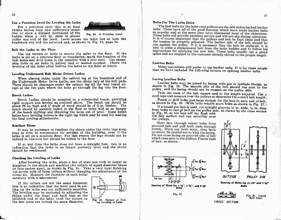
Ucc a Precision Level for Leveling the Latte
Use a precision level that is at leasttwelve inches long and sufficiently sensi-tive to show a dlstinct movement of thebubble when a .003 in. shim ls placedunder one end of the level. Level across the lathe bed at both theheadstock end and the tailstock end, as shown in Fig. 23' page 16.
Bolt the Lathe to the Floor
Use lag screws or bolts to secure the lathe to the floor. U thelathe is set on a concrete floor or foundation, mark the location of thebolt holes and drill holes in the concrete with a star drill. Use expan-sion bolts or set bolts in melted lead or melted sulphur. Check thelevellng of the lathe after bolting the lathe to the floor or bench.
Leveling Underneath Belt Motor Driven Latler
IMhen placing shims under the cabinet leg at the headstock-end ofthe Underneath Motor Drive Lathe, use the shims only at the bolt pads.There should be clearance under the cabinet leg all the way round ex-cept at the two pads where the bolts go through the leg into the floor.
Bench Lathes
Bench Lathes should be mounted on a substantial bench, providingrieid support and leveled as outlined above. The bench top should beab-out 28 ln hish and if made of wood should be of 2-in. lumber. Thebench should be securely bolted to the floor so there will be no dangerof the bench shifting and throwing the lathe out of level' Some benchlathes have leveling screws in the right leg which may be used for makingthe final leveling adjustments.
Reedjurt ShimaIt may be necessary to readJugt the shims under the lathe legs from
time to time to compensate for settling of the builtling, even if thelathe is set on a concrete floor. For this reason the legs should not bebedded in concrete but should be boltetl to the floor.
If at any time the lathe does not bore a straight hole, thls is anIndication that the lathe is no longer perfectly level and the shimsshould be readjusted.
Chccking the Levcling of l-athe
After leveling the lathe, place a bar of steel one inch or larger indiameter in the chuck and machine two collars of equal diameter threeor four inches apart, as shown in Ftg. 25. Take a very litht flnishingcut across both of these collars without changing the adjustment of thecutter bit. Measure the diameter of each collarcarefully with a mlcrometer.
If the collars are not the same diameter,this is an indication that the level used in set-ting up the lathe was not sufficiently sensitive.The leveling may be perfected by acljusting theshims under the front and back legs at thetallstock end of the lathe until the collars onthe test piece are turned the same dlameter.
Belta For The Lathe Drive
Leather Belts
.. Many machinist-s qtit] prefer to use leather bert-s.. Jt i9 fo1 these peoplethat we have included th6 following section-orr"pti"i"!-i"rtrr"i r!ri"."
Lacing Leather Belts
l:.!l"Ll"lt:.-iy, !"_ jli":g by, tacing. with.gut or _rawhide thongs, asLearner belts mav be Joinest by. laci-ng- with gut or rawhide thonqs. asshown in Fig. 26. The.sirooth side ;a;h;-L;t;-s1;H ;;;i,JiTi3"lr,"pullev, and the lacine should not h" ";;;;
Li, *1,- nrru-., -ir^pulley, and the lacing should not be
"-;; "ii tt"-p"ff* i'ia'i.
t7
Fit. 24. A Precision Level
'l'rim the ends of the be.rt squ.are and to the length required. use asteel tape and measure over the poueys ttdea;r;i;e;il8;;;ff;;ill"iitn.Punch or drill holesjust,la,rge enough for the-lace in each end of blert,as shown in Fig. 26. (Wide belts require *""" iiot"" ," Jn"i,iii irili'."zz.l
lt*^*:* g:j t:.":,jL*:1,"i"1.1,t'^3iglJ_6'r9ov9s % in. wide, \6 i;. dee;from hoieJto ;;d of i;il on thein Fig. 26, so the laie will lavrrom noles to end of bert_on the pulley side, as shown by the dr<iis
"e"tio'ir-r F!s.- 26, so the lade will Uv nir"it .i'iti -' *" '
the bil! surface and run d;;hit ;;;;the pulleys.
Sprcing of Hofcr for I-96,', l-jg,', a6 2-y,,
L. rlir.r
r.. tti..,'r-z{b..t ouTstoE PULLET
'DEgprcinS: of Bofce Io" 16/16r, t nA L%nBcltt
FiC. 25. Method ol Te;t 'in4 Levelinl ol Lrthc
\
Fle. zz. Fle.26. LacedBelt Jolnt

I18
Wine Belt HooksThere are a number of good wire belt hooks on the
market that can be used for splicing belts. Measure for thelength of the belt in the same manner as outlined above andthen deduct enough more, before cutting, to allow for theconnecting pin (See FiS.28). Wire belt hooks should neverbe used on any belt which is not completely guarded orwhich may be shifted while the machine is running.
Glued Belt Splice Belt Hooks
The cemented endless belt splice is preferred by many mechanics be-cause, when properly made, it is very durable and will run over the pulleysmore smoothly than a laced or wire hook splice. A good waterproof typeof belt cement should be used. Experience has shown that a belt splicemade with good acetone cement is practically permanent and is- notsubject to ordinary moisture or oil action.
by the drawing, Fig. 29. Use a belt shave,small plane, or sharp knife to cut smooth,uniform tapers. Prepare two blocks ofsoft one inch wood, a little wider than thebelt, and six inches long.
Place the belt around the cone pulleysand apply cement according to directionsof the cement manufacturer. Press thefreshly cemented joint together and im-mediately lay on one of the wood blocks.Nail the belt, through the joint, to theblock of wood with two or three smallnbils, This will prevent the splice fromslipping or becoming crooked. Place theother block of wood on top of the jointand clamp firmly, using "C" clamps.Allow the cement to dry thoroughly be-fore removing the clamps. Scrape anyexcess cement from thb surfaces of thebelt before using it.
Fig. 29. Cemented Endlei BeltSplice
Belt Tension on Lathe DrivegMaintaining the proper running tension for the flat leather belt and
V-belts is of the grealest importance. Belts which are allowed to run loosewill creep and slip and cause an over-all loss in the cutting efficiency of theIathe, and damage may result to fine work due to variation of cuttingspeeds. Belts which are run under too much tension overload the lathe andlathe drive. This results in loss of power, excessive bearing wear, causesthe motor to run hot, and stretches the belts until they have to be shortenedor replaced, Routine checking and adjustment of the belt tension, accord-ing tb instructions given in the following paragraphs, will keep thelathe efficiency high and repair expenses low.
\
19
Horizontal Motor Driven Lathe BeltaThe lathe should be stopped before the flat belt is shifted on the cone
pulleys. Release the belt tension by pulling lever "C" forward, as shownin Fig. 30, and then shift belt to change spindle speeds.
To change flat belt tension, adjust turnbuckle "A" with lever "C" inthe back (or down) position. Test tension by pressinE down on belt midwayposition. Test tension by pressing down on belt midway
pulleys. Belt should depress about one inch. If beltbetween the cone pulleys. Belt should depress abbut one inch. If belislips under power and tension is correct, it is probably oily and shouldslips under power and tension is correct,be cleaned with naphtha or benzol.be cleaned with naphtha or benzol.If the belt appears dry and stiff,a little neat's-foot oil will makeit pliable.
Adjust V-belt tension by mov-inE motor on its standard. Loosenthe four screws at "8," Fig. 30.After moving motor, t ightenscrevr's. When properly adjustedV-belt should denress about oneinch midway b6tween pulleys,but must still be stretched tightenough to feel alive when tappedwith finger tips. Check pivotscrews at "8." If necessary, ad-just so they are snug and tightenlock nuts.
Underneath Motor DrivenI:the Beltc
Belt tension release lever "A" (Fig.31) permits releasing cone pulley belttension for shif t ing belt to changespindle speeds. See drawings of under-neath motor drives, pages 8 and 9,Figs. 11, 12, 73, and 14.
Screw "C" adjusts tension of thecone pulley flat belt (see Figs. 12 ald31). This'adjustment must be madewith lever "A" in running position. TheIathe shown in Fig. 11 has turnbucklefor making this adjustment.
Screw "8" adjusts tension of themotor V-belts. Turn nuts above andbelow motor mounting plate (Figs. 13and 31). Adjust V-belt tension on latheshown in Fig. 11, the same as shownin "Horizontal Motor Driven LatheBelts," above.
Belts should be just tight enough totransmit the required power withoutslipping. Pressing the hand against aproperly adjusted flat belt near the conepulley should depress belt about %".The V-belt, midway between pulleys,should depiess aboui 1". Belts inav bricleaned with naphtha or benzol and theflat belt treated with neat's-foot oil. asmentioned above on this page.
Fig. 31. Cres Setion of Under-neath Belt Motor Drive Showing
Cone Pulley Belt and V-b€ltl
Fig. 30. End View of Eorizontrl MotorDriven Bench Lathe Showing Belt Tep
sion Adju8tment

20
Ft!. 32. Oiling Chart for a l-athe
Oiling the Lathe
Oil every bearing of a new lathe before starting it. Use high gradeoils of proper viscosity as specified on the metal Lubrication Chart at-tached to each lathe. The lathe should be oiled twice daily for the first weekit is used and once a day thereafter. Never oil the lathe while it isrunning and be certain that machine oil is used, not automobile engine oil.
Keeping the lathe well oiled has much to do with the length of itslife and the quality of the work it will turn out. Follow the directionson the metal lubrication chart carefully if you wish to keep your lathein first class condition.
Always oil in the same order so that no oil holes will be missed.If you do this the oiling will become a habit and will require only avery short time.
Do not use- an excess of oil. A few drops in each oil hole is sufr-cient, and if more is applied it will only run out of the bearings andget on the lathe, making it necessary for you to clean it more fre-quently.
Oil the motor and drive bearings as specified in instructions suppliedwith the lathe. This is very important. Do not allow dust, chips or otherdebris to collect around the motor so it will overheaL An excessive rise inthe motor running temperature will cause damage to its bearings andwindings.
After you have completed the process of oiling the lathe and motordrive, wipe off the excess oil around the bearings with a clean clothor waste. Keep the lathe clean. Do not allow oil, dirt, chips or rust tocollect any place on the lathe.
\
Chapter III
OPERATION OF THE LATHE
Before start ing a new lathe, the operator should careful ly study theaction of the various parts and become thoroughly famil iar with theoperation of all control levers and knobs.
The principal parts of the lathe are shown below in FiS. 38. Be-come familiar with the name of each part as they will be referred rofrequently in the fol lowing pages where detai led information on theoperation of the lathe is given.
Do not operate the lathe under power until it is properly set upand leveled, as outl ined on page 15. Also make sure that al l bearingshave been oiled and that the belt tension is correct. Always pull thecone pulley belt by hand to make sure the lathe runs free before start-ing the lathe under poriler.
Fig, 33. Nanes of the Principal Parts oI a Lathe

22
Operation of HeadstockSpindle speeds are chanted by shifting the belt from one step ot
the cbne pulley to another and by engaging or disengaging the backgears. Th'e colie pulley steps are numb-ered in the illustration above tocorrespond with the numbers in the tabulat ion on page 23, which showsthe normal spindle speeds for various sizes of lathes.
Direct Belt DriveTo arrange the lathe headstock for direct belt drive, push tle back
gear lever back as far as i t wi l l go; then pul l out and up o! the bul llear lock pin and revolve the cone pulley slowly by hand until the bull
lear lock slides into position and locks the cone pulley to the spindle'
Back Geared DriveTo engage the back gears for slow spindle speeds, pull the bull gear
lock oin ouf and Dush it down to disconnect the cone pulley from.thespi"Ai"; then pull^the back gear lever forward. Revolve the cone pulleyl-i ita"h to m-ake sure the back gears are properly engaged. Do notentage the back gears while the lathe spindle is revolving.
Bull Gear Lock, Plunger TypeOn some lathe headstocks the plunger type bull gear lock is used.
For direct belt drive on these latbes the bull gear lock pin is pushed in'and for back-geared drive it is pulled out.
Feed Reverse Lever
Fig. 34. Operating Parts of Lathe Headstock
\
23
Spindle Speeds of Lathes
The spindle speeds for various sizes of lathes are listed in the tabula-tion below. The columns under which the speeds are listed are numberedL, 2, 3, and 4 to correspond with the numbers on the cone pulley steps inFig. 34, page 22. For example, those spindle speeds that aie listed underColumn I are obtained when the cone pulley belt is placed on the conepulley step marked I in the illustration, Fig. 34.
SPTNDLE SPEEDS OF LATHES
Approximate Spindle Speeds in Revolutions Per Minute
Direct Belt, Drive Back-Gear DriveSizeof
Lathe
Tvpeof
Drive
9" Bench 6-speedflat belt
9" Bench &Self-Contained
9" Bench &spccdV-belt
9 'Bench &Self-Contained
l6-speedV-belt
9" & lGti U.M.D.flat belt
9" & 10-K U.M.D.V-belt
l ( lK l lench& Self-Contruincr l
l2-speedflat belt
UighLow
10-l i l icnch& Self-Contoincd
l6-speedV-belt
250.134
350 26?
7E0410
265.r35
276.t37
265.130
SpeedRange
HighLow
HighLow
HighLow
64
r0054
r30
300150
130
250125
340170
405
470
790400
130
90OU
9648
t05JA
5227
6030
4020
5025
30l5
DUD
272
265.r30
Jlu285
2W.r30t2565
13567
13567
r3065
130oc
270r35
2r5ro7
570285
l0 l0495
898470449235
628314
457248
545272
oou278
235
446244
662362
460240
760370
fi2244
760370
418209
900490
l0 l0495
844415
424214
610305
t75437
945475
78
1458l
96
t79'95
155*7A
3
DU
8650
HiehLow
150',o
150.
l3-incb
l3-inch &13-inch Turet,
lGinch &lGinch Turret
r4l$-itch
14}d-irch
3-steppulley
,l-st€ppulley
3-stcppulley
4-steppulley
270r35
350175
2t5ro7
390195
4020
3-st€ppulley
l6-inch
lF24-inch &speed
l6'24-inch &epeed
1624-inch 12-speed
l6-24-inch l6-speed
4-st€ppulley
HiehLow 1
980490
lCrinch &l(Linch Turrct
HighLow I
3-steppulley
HighLow
460230
5.50274
HighLow
eoo I455
|tIt is not recommcndecl thst back-gears be engaged when drive is operatcd at high speedf.,Lvailable only witlr 2-speed motor.
r270
640
t200640
r365I to
1365670
143570{
195'95
165.80
r95.95
160.t5to42
9045
HigbLow
HiehtLow t
HighLowf
HighIpwl
IIighLowt
HighInwt
7l35
8040
6l30
t040
7033
30
35

24
Compound Rest Koob
Corrioge lock S<rew
Feed Chonge Lever
Holf Nur lever
Automotic FeedFri . t ion Clut(h
Fig. 35. Op€rrting Psrts ol Lathe Carri&ge and Apron
Fic. 35A. Micrcmeter Coller onCros Feed Screw
Microrneter CollarsOn newer machines each graduation on the micrometer collarc on the
cross-feed screw and compound screw represents a reduction of the diameterof the work on one-thousandth of an inch. On manv older lathes eachgraduation represented tool movement of one-thousa;dth of an inch orreduction of the diameter of two-thousandths. The graduated collars maybe set at zero by releasing the set screws which lock them in position.
Power Carriage FeedsThe power feed friction clutch controls the operation of both the
power longitudinal feed and thef,ne power cross leed. Inere are generauyng the clutch; either a handle or knob. In
feed. There are generallyher a handle or knob. Intwo methods used for operating the clutch; either a handle or knob. In
general, the handle is pulled upward or the knob turned to the right to
Operation of l-atLe Carriageend Apron
The principal operating parts ofthe Iathe carriage and apron areshown above in Fie, 35. The apronhand wheel is turned- to move the'car-riage along the lathe bed, and thecross feed knob and compound restknob are turned to move the toolrest in and out. The carriage lockscnew is used to loek the carriageto the lathe bed. This screw shouldnever be tightened except for facingor cutting-off operations.
general, the handle is pulled upward or the knob turned to the right toengage the clutch, and the handle pushed down or the knob turned tothe left to disensase the clutch. The direction of the feed is controlled
Power Carriage Fee&on Quick ChangeGear Lathes
A wide range of powerIongitudinal feeds and powercross feeds is available on allQuick Change Gear Lathes.To obtain any desired feed itis only necessary to arrangethe levers on the gear boxaccording to the direct read-ing index chart shown inFig. 38. The threads per inchare shov/n in large figureson the index chart below.The smaller figures indicatelhe power longitudinal turn-ing feeds in thousandths ofan inch. See page 74.
Fig. 38. Index Chart for Quick Change Gear Lathe
Power Carriage Feeds onStan&rd Change Gear Lathes
Standard Change Gear Lathes areequipped with a set of independentchange gears for cutting screw threadsand obtaining various power longi-tudinal feeds and power cross feeds.Compound gearing is used for finethreads and feeds. See pages 72 and,t1.4.
A large t'screw gear" should beplaced on the lead screw and a small"stud gear" on the reverse stud. Thesetwo gears should be connected withidler gears as sholrm. To obtain fineror coarseT feeds, use a smaller orlarger "stud gear-t'
25
the left to disengage the clutch. The direction of the feed is controlledby the position of the reverse lever on the headstock. (See page 22.)
The feed chanqe lever has three positions: "uD" for loneitudinalThe feed change lever has three posilfeeds, "down" for cross feeds, and "center"
The feed change lever has three positions: "up" for longitudinal
for neutral.The halfnut lever is used onlv for thread
cutting. The feed change lever-must be inthe "center" or neutral position before thehalf nuts can be engaged.
Operation of TailstockThe tailstock may be locked on the lathe
bed at any position by tightening the clampbolt nut. To lock the tailstock spindle,tighten the binding lever.
Fig. 37. Quick Change Gear Mchanism
Fig. 39. Standard Change GearMechanism
l-
Fig.36. Tailetock

26
Notes on LatLe \lfork
A mixture of red lead and machlne oll ls a good lubricant for thetallstock center of a lathe.
A preclslon level that wi l l show an error of.003 ln. per foot shouldbe used to level the lathe when installing, as a level lathe will assure
Brecision accuracy of the work.
Clean and oil the threads before screwing a chuck or face plateonto the lathe spindle.
After grinding a tool, hone it to a keen etlge with an oil stone-the cutting edge will last longer.
Always make sure the spindle taBers of the lathe are clean andtree from burrs and dirt before inserting tbe lathe centers.
If the face plate or chuck does not run true, examine the shoulderof the lathe spindle and face of hub on face plate or chuck back forburrs, dirt, etc.
'When cuttlng screw threads in steel, use a small brush to spreadoll on the work preceding each cut. Lard oil ls preferable, but a goodmachlne oll or cutting oil will do.
Ure Flat Leather Beltr
Flat leather belts are recommended for use on lathe cone pulleys.
Leather belts are better than canvas or rubber belts for use onlathe cone pulleys. Leather belts are more efrcient, last longer, havemore elasticity and give better service.
If a belt has a tendency to come ofr from the pulley there is some-thing wrong. Usually the pulleys are out of aligrrment. Find out whatthe trouble is and remedy it. Do not try to hold the belt on the pulleywith a brace.
Notec on Beltr and Pulleye
To find the approximate length of a belt, multiply half the sumof the pulley diameters by 3-l/7 and add twice the distance between thepulley centers.
The smooth side of the belt should always run next to the pulley.
Keep belts clean and dry. Do not allow moisture, machine oil ordirb to collect on them.
A pulley should be about 70/s wid'et than the belt.
Driving pulleys for shifting belts should have flat face, all otherDulleys should be crowned.
For stepped or flanged pulleys double ply belttng ls'better thanelngle Bly belting.
Don't shift a moving belt by hancl; use a stick or belt shifter.
Never put a belt oD a pulley while it is revolvlng rapldly.
A belt may run crooked lf the ends are not cut square beforelacing, or if laced unevenly.
Don't run belts too tlght, or with the flesh slde nert to the pulley.
\
Flg. 49. Enurllng Tool
Chaptet IV
LATHE TOOLS AND THEIR APPLICATION
In order to machine metal accurately and efficiently, it is necessaryto have the correct type of lathe tool with a keen, well supported cut-ting edge, ground for the particular kind of metal being machined, andset at the correct height.
High speed steel cutter bits mounted in forged steel holders, asshown in Figs. 40, 46, 48 and 50, are the most popular type of lathetools. The 10-in-1 Tool Block shown in Fig. 50A may be used inplace of the individual tool holders if desired. See page 98.
The boring tool, cutting-ofr tool,threading tool and knurling toolare required for various classesof work that cannot be readily ac-complished with the regular turningtool.
Flg. 40. Tool Eoliler f,lth Cutrter Btt
PFtg. 41-A Grtnillng
Flg. 42. Cutter Blt After Grlnrtlng
.6. Str4lght
Frg. 41. Ungroud Cutter Blt
Eolaler lorCu0tcr Bttg
t38E3sABCDD
L. E. Roud B. E. L. E. Threatl-TuniEg Nose TtrDlng Slde lns
Fici. 44. Set ol Grouil Crttet
FRE.Sid€
Bits
Ftg. 47. Threaaltng Tool Ftg. 48. Lefi Eanil Tool Eolalor
Flg. d0. Blght E&nal Tool Eolder
,1
Flg.60A. 10-ir-r
Tool Block. see
psge 9E.
Flg, 45. Cuttlng-ofl Toot

28
Conect Height of Cutting Edge
The cutting edge of the cutter bitshould be about 6' above eenter, or8/64 in. per inch in diameter of thework, as shown in Fig. 61 at right forordinary straight turning. The posi-tion of the cutter bit must be takeninto consideration when grinding thevarious angles, as the height of thecutter bit determines the amount offront clearance necessary to permitfree cutting.
The cutting edge of the cutter bitshould always be placed exactly oncenter, as shown in Fig. 62, for alltyires of teper turning and boring, and for cutting screw threads, also forturning brass, copper and other tenacious metals.
Tool Angle Valiet
The included angle of the cuttingedge of a cutter bit is known as thetool angle or angle of keenness andvaries with the texture of the work tobe machined. For eiample, when turn-ing soft steel a rather acute angleshould be used, but for machining hard steel or cast iron the cuttingedge must be well supported and therefore the angle is less acute.
It has been found that an included angle of 61" is the most efficienttool angle for machining soft steel. This is the angle of the cutter asshown in Fig. 53. For machining ordinary cast iron, the included angleof the cutting edge should be approximately 71". However, for machiningchilled iron or very hard grades of cast iron, the tool angle may beas great as 85o.
Cutter Bit Grinfing Gauge
A cutter bit grinding gauge, shown in Figs. 64-A, 64-8, ancl 64-C,is helpful for grinding the correct angles on the cutter bit.
Fier.54-A- ChekingSide Cl@rce
Ffu. 64-C. f,ftalin8Tml Angle
Atg. 61. Cutting &lge Abow Ceoter
Fic. 52. Cutttna Edgs On Center
Fig. 53. TooI Arule for Steel
Fle. 548. CheckingFront Clwance
\
Fie. 62. HoniotFi{. 61. Griodind the Cutting EdgcSite Re ke snd oI Cutter Bi t wi tb
Back Rake an Oil Stonc
a.
Grinding Lathe Tool Cutter Bits
The angle of the cutter bit t'itbthe bottom of the tool holder mustbe taken into consideration whengrinding cutter bits.
The sid.e clearance (Fig. 55) isto permit the cutting edge to advancefreely without the heel of the toolrubbing against the work.
The front clearance (X' is. 56) isto Bermit the cutting edge to cutfreely as the tool is fecl to the work.
Too much clearance will weakenthe cutting edge so that it will break;but insufficient clearance will prevent
the tool from cutting.
Side rake and back rake (X'igs.55 and 56) also facilitate free cut-ting. X'or cast iron, hard bronze andhard steel, Yery little side rake orback rake are required. (See page
28.)
The angle of keenness (Fie. 55)may vary from 60o for soft steel tonearly 90o for cast iron, hard steel,bronze, etc,
X' igs.57 to 61, inclusive, showthe various steps in grinding a cut-ter bit for general machine work.Iloning the cutting eclge (Fig. 62)will improve the quality of the finishand lengthen the life of the tool.
Fi!. 59. GrindintFront of Cutter
Bit
FiC. 60. RoundingBnd oI Cutter
Bit
SIDE CLE APAXCE3"T0 t0' -
Fig. 55. Correct Side Clearance and SidcRak€ of Cutter Bit
56. Correct Front Cleararco audBack Rako oI Cutter Bit
Fid.
Firl. 57. Grindin6 Fid. 58. GrindinrLeIt Side oI Cutter Right Side of Cut-
Bit ter Bit

),
to leave sufficietrt stock for a finishinecut with the round nosed tool showi Fig' 63' Applioation of Rou{hin{ Tool
at the bottom of the page. 't"
Grind the tool to the shape shownln I'lg. 64, and s'ee Flgs. 55 and 56 on:\
-V64-R2t jt'
page 29 for information on grinding the :r'>>/correct front clearance, etc. 4-
-The cutttng edge of the tool is
Torvro**-r"
straight and the point is only slightly
30
Cutter Bit for Rough TurningFigs. 63 and 64 illustrate r-d"i-
lent tool for taking heavy roughinjcuts to reduce the diameter of a steelshaft to the aBllrorimate size desired.This tool will cut freely but does notproduce a very smooth flnish, Whenusing this type of tool it is advisable
cutting quality of the tool.
The tool angle or lnclutletl angle ofthe cutting eAg9,-o{-tnis tool should beapprorimateldGl" for ordinary machinesteel. If a hdlder grade of alloy ortool steel itrtti be. machined, the anglemay be increased,'gnd if free cuttingBessemer screw $tocli is to be machined,the angle hay be slightly less than 610.
Hone the cutting etlge of the toolwith a small oil stone. This will lengthenthe life of the tool antl it will cut better.
Cutter Bit for Finish TurningX'igs. 65 and 66 illustrate a round
nosed turning tool for taking flnishingcuts. The tool is very much the sameshape as the more pointed tool. forrough turning shown above, except thatthe point of the tool is rounded. (Ap-prorimately $ tn. to t in. radius.)
This tool will produce a very smoothflnish if, atter grrnding, the cuttingedge is well honed with an oil stone ande fine power carriage feed is used.
Fi6. 64. Detoil oI Roulhint Tool
Fig.65. Applidtion ef Finiehin! Tool
rounded. A very small radius at rhe :Doint (approximarely dI in.) rvill pre- :/ven[ the poinu of the tool from break- ffilng down but will not impair the free
\*.
Firl. 66. Detail of Finichint Tool
3l
Fid. 67. Application oI Round Nosed Tool
Round Nosed Turning Tool
Fig. 68, Detail of Round Nosed Tool Bit
The round nosed turning tool shown above is ground flat on top sothat the tool may be fed in either direction, as indicated by the arrowstn Fig. 6?. This is a very convenient tool for reducing the diameter ofa shaft in the center. The shape of the cutter bit is shown in Fig. 68,and the correct angle for the front clearance and side clearance can beobtained by referr ing to Figs, 55 and 56, page 29.
Fi6. 70. Detail $r11,f,
Hand rurn.Fit!. 69. Applioatioo oI Right Hand Turnin! Triol
Right Hand Turning ToolThe right hand turning tool shown above is the most common type
of tool for general all around machine work. This tool is used formachining work from right to left, as indicated by the arrow in Fig. 69.The shape of the cutter bit is shown in Fig. 70. See page 29 for correctangles of clearance.
Fi!. 71. Application oI Left Hand Turning Tool
Left Hand Turning Tool
wToD Vlcw
ruWSlde Vlcw End vlcw
Fi!. 72. Detail of ol-eft
Hand Tuminl
The left hand turning tool illustrated in Figs. 71 and 72 is Justthe opposite of the r ight hand turning tool shown in X' igs. 69 and 70.This tool is designed for machining work from left to right.
I32
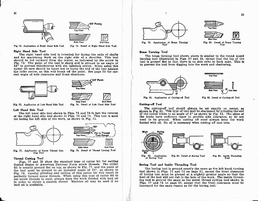
Fi8. 73. Application oI Ridht Hcnd Side Tool
Right Hand Side Tool
The right hand side tool is intended for facing the ends of shaltsand for machining work on the right side of a shoulder. This toolshould be fed outward from the center, as indicated by the arrow inFig. 73. The point of the tool is sharp and is ground to an angle of68' to prevent interference with the tailstock center. When using thiscutter bit care should be taken not to bump the end of the tool againstthe lathe center, as this will break off the point. See Bage 29 for cor-rect angle of side clearance a.nd front clearance.
Fi!. 75. Application oI Left Hand Side Tool
Left Hand Side Tool
#*'PohtToD vlcw
WWsld. Vlcw Eid Vlcw
Fid. 76. Detail of Left Hand Side Tool
The left hand side tool shown in X'igs. 75 and 76 is Just the reYerseof the rieht hand side tool shown in Figs. 73 and 74. This tool is usedfor facing the left side of the work, as shown in Fig. 75.
Fig. 74. Detail of Ri{ht Hand Side Tool
q-:_ -\.^1- .An"Ex: \
- '
( Ftt to Tnrced ;Toe Vtowi__'!:ot .G:uec_ _l
Fid. 77. Applic".li"'C'+r:f*- Thrad Cut-
Thread Cutting Tool
Fid. 78. Detail of Thrad Cuttin{ TooI
Figs. 77 and ?8 show the standard tyBe of cutter bit for cuttingUnited- States or American National Form screw threads. The cutter
lard oil is available.
Sldc Vlcw
\I
33
Fit, 79, Anelietim, of Brus Tuminl
Brasc Turning Tool
The brass turning tool shown above ls simllar to the round nosedturning tool illustrated in X'igs. 67 and 68, except that the top of thetool ls ground flat so that there is no side rake or back rake. This lsto prevent the tool from digging into the work and chattering.
.WTurnin!
=ToDVl.!
#Fitf 80. Detail ofrBraee
Fid. 81. Application ol Cuttin!-ofi Tool
Tcp Vbw
I-
- ra. Sld! Vl.w + -) End Vtd
It\-/
Fitl. 82. Detail of Cuttiu!-ofr Tool
Cutting-ofr Tool
The cutting:+ff tool should always be set exactly on @nt€r, asshown in Fig. 81. This type of tool may be sharpened by grinding th€ endof the cutter blade to an angle of 5o as shown in Fig. 82. The sides ofthe blatle have sufficient taper to provide side clearance, so do notneed to be ground. When cutting ofr steel always keep the workflooded with oil. No oil is necessary when cutting ofr cast iron.
Fitl. 84. Deteil of Borio! Tool Fi8. 85, Ireide TbreadinS
Boring Tool and lnside Threading ToolThe boring tool is ground exactly the same as the left hand turning
tool shown ln Figs. 71 and 72 on page 31, ercept the front clearanceof boring tool must be ground at a sllAhtly greater angle so that theheel of the tool will not rub in the hole of the work. The inside thread-ing tool is ground the same as the screw thread cutting tool shown inFigs. 77 and 78 on pag€ 32, ercept that the front, clearance must belncreasr:d for the same reason as for the boring tool.

34a!
Stellite Cutter Bits
Stellite cutter bits will standhigher cutting speeds than high speedsteel cutter bits. Stellite is also usedfor machining hard steel, cast iron, bronze, etc.
Stellite is a non-magnetic alloy which is harder than ordinary highspeed steel. It will stand very high cutting speeds and the tool willnot lose its temper even though heated red hot from the friction gener-ated. by taking the cut.
Stellite is more brittle than high speed steel, and for this reasonshould have just enough clearance to permit the tool to cut freely, a6the cutting edge must be well supported to prevent chipping andbreaking.
Tungsten Carbide Cutting ToolsTungsten carbide tipped cutting
tools are used for manufacturing op-erations where maximum cuttingspeeds are desired, and are highly effi-cient for machining cast iron, alloyedcast iron, copper, brass, bronze, alumi-num, babbitt and abrasive non-metallicmaterials such as fibre, hard rubberand plastics. Cutting speeds may varyfrom 110 to 650 surface feet per min-ute, depending on the depth of cut andthe feed.
Tungsten carbide tipped cutter bitsmust be ground on a special grade ofgrinding wheel, as they are so hardthey cannot be satisfactorily groundon the ordinary grinding wheel. Thecutting edge must be well supported toprevent chipping and should have justenough cl'earance to permit the tool tocut freely.
Tantalum Carbide Cutting TmlsTantalum carbide is a term applied
to a combination of tungsten carbideand tantalum carbide. Tantalum car-bide tipped cutting tools are similar totungsten carbide tools, but are usedmostly for machining steel.
Titanium Carbide Cutting ToolsTitanium carbide is a term applied
to a combination of tungsten carbideand titanium carbide. Titanium car-bide is interchangeable with tantalumcarbide in its uses.
35
Flg. E8. Carbide Tippeil Cutting ToolMouted ln 10-in-1 Tool Eolder for Bigtat
sulrport
Itttlt.)\
Fis. 87. Steuite Gutts Bit
Fig. 86. Nine of the Most Popular Shapes of Lathe Tool Cuttcr Bitr rndTheir Application
Fi8:. 88A. Machlning a Steel Shsft &tElgh Speeal with C&rbiile TiDpeal Cut-
tiDg Tool

I36
Cutting Tmla for Non-Fenous Materials
Machining Soft MetalsAluminum, magnesium alloys, and other comparatively s-oft -metals
require keen i:dsed tools with more clearance' front rake' and side rakethdn the harder metals. To increase the amount of back rake, the cuttingedge of the tool is sometimes placed high above center. This, of course'cainot be done when turning tapers or facing, and frequent readjustmentis necessary when the diameter of the work varies.
When machining tenacious metals such as pure copper the cutting toolshould be honed to-a very keen cutting edge to prevent tearing the workand nroducinE a rouEh finish. Light cuts at medium feeds with a round nosetool having tSz" t;l/16" nose iadius usually produce best results.
Machining Pl,asticc
edge of the tool will dull quickly at lower speeds.
CUTTING SPEEDS AND TOOL ANGLES FOR NON-FERROUSMATERIALS
See Figs. 55 and 56 P.g" 29 for tool angle diagrans
MaterialCuttiugSpeedf. p. m.
FrontClearanceDegrees
a
o6
10t27
86
1010o88
20
SideClearanceDegrees
8
58
15
a
86
t210688
20
BackRake
Degreee
3000,
151086.7
300
1030I
30
SideRako
Degrees
300-400300-700300-700150-30075-15075-150
225-35027540050-r70
20H0020H00200-s00200-60050-150
400-800
200Llh7
2525t0
t
12250
20300
30
aKerogene lubricant ueed.
These are suggested starting angles for g:eneral work'- Slightly smalleror larger aneles*;ay prove moie eficient, depending on the texture of thematerial ma;hined and the type of cutting tool used.
L
37
Fig.97. Measuring with an Outside Caliper
\
Chapter V
HO\$r TO TAKE ACCURATE MEASUREMENTS
The ability to take accurate measurements can be acquired onlyby practice and experience. Careful and accurate measurements areessential to good machine work. All measurements should be madewith an accurately graduated steel scale or a micrometer. Never usea cheap steel scale or a wood ruler, as they are likely to be inaccurateand may cause spoiled work.
An experienced mechanic can take measurements with a steel scaleand calipers to a surprising degree of accuracy. This is accomplishedby developing a sensitive "caliper feel,' and by carefully setting thecalipers so that they "split the line" graduated on the scale.
Setting an Outside CaliperA good method for setting an
outside caliper to a steel scale isBhown in f ig. 96. The scale ishelcl in the left hand and thecaliper in the right hand. Oneleg of the caliper is held againstthe end of the scale and is sup-ported by the finger of the Iefthand while the adjustment ismade with the thumb and flrstfinger of the right hand.
Measuring with CalipersThe proper appl icat ion of the
outside caliper when measuringthe d.iameter of a cylinder or ashaft is shown ip Fig. 97. Thecaliper is held exactly at rightangles to the center line of thework and is pushed gently backand forth across the diameter ofthe cylinder to be measured.When the caliper is adjustedproBerly, it should easily slipover the shaft of its own weight.Never force a caliper or it willspring and the measurement willnot be accurate.
Fig. 96, Settin{ an Outsido Caliper

I38
Setting Inride Calipers
To set an lnslde caliper for adefinite dimension, place the end ofthe scale against a flat surface andthe end of the caliper at the edgeand end of the scale. Hold the scalesquare with the flat surface. Atliustthe other end of the caliper to therequired dimension.
Measuring Inside DiametersTo measure an inside diame-
ter, place the caliper in the holeas shown on the dottetl line andraise the hand. slowly. Adjust thecaliper until it will slip into thehole with a very slight drag. Begure to hold the caliper squareacross the diameter of the hole.
Transferring MeasurementsIn transferring measurement
from an outside caliperto an inside caliBer, thepoint of one leg of thelnside caliper rests on asimilar point of the out-side caliper, as shown inFig. 100. Using thiscontact polnt as a pivot,
move the inside caliperalong the dotted lineshown in illustration,and adjust with thethumb screw until you feel your measure-ment is Just right.
Hermaphrodite Cdiper
The hermaphroclite caliper shown lnI'tg. 101 is set from the end of the scaleexactly the same as the outside caliBer.
Caliper FeelThe accuracy of all contact measurements is dependent upon the
sense of touch or feel. The caliper should be delicately antl lightly heldin the finger tips, not gripped tightly. If the caliper is trlpped tightly,the sense of touch is very much impaired.
Fi8. 98. Setting an fnaido Calipor
Fi6. 99. Maaurin! with Inaido Caliper
Tranelerint B Measurement fron an IneidcCaliper to sn Outeids Caliper
\-.
39
How to Read a Micrometer (Engtish Measurement)
Each graduation on the micrometer barrel ..D" represents one turnof the spindle or .025 in. Every fourth graduation is numbered andthe f lgures represent tenths of an inch since 4x.02b in,: .100 in. orft of an inch.
The thimble "E" has twenty-flve graduations, each of which repre-sents one-thousandth of an inch, Every trfth graduation is numbeied,from five to 25.
The micrometer reading is the sum of the readings of the gradua-tions on the barrel and the thimble. For example, there are sevengraduations visible on the barrel in the illustration above. Since eachgraduation represents .025 in., the reading on the barrel is ?r.02b in.or .175 in. To this must be added the reading on the thimble whichis .003 in. The correct reading is the sum of these two figures or.175 in. + .003 in. : .178 in. Therefore this micrometer is set for adiameter of .178 in.
Metric System Micrometer
Micrometers for measuring in the Metric system are graduated toread in hundredths of a mil l imeter as shown at r ight in Fig. 103. Foreach complete revolution the spindle travels 1y'2, mm or .50 mm, andtwo complete revolutions are required for 1.00 mm. Each of the upperset of graduations on the barrel repre3ent 1 mm. (two revolutions otthe spindle) and every f l f th graduation is numbered 0, 5, 10, 1b, etc.The lower set of traduations subdivides each millimeter division intotwo parts.
The beveled edge of the thimble ls tlivided into 50 graduations, eachof which represents .01 mm.
The micrometer reading is thesum of the readings on the barreland the thimble. For example, in Fig.103 there are three millimeter gradua-tions visible on the barrel, also a Yzmm graduation. The reading on thethimble is .36 mm. Thereflore. thereading is 3.00 mm + .50 mm i .36mm = 3.86 mm.
A-FRAMEB-ANVILC-SPINDLED-BARRELE-THIMBLE
Fis. 102. An Outside Mi-crcmeter Caliper for EnglishMruurements Reading in
Thoumndths of m Inch
(Courtesy IJ. S. Starrett Co.)
Fig. 103. Metric Microneter(Courtesy Brown & Sharpe
Mfg. Co.)

Use of Toolmaker'c Buttonr
Toolmaker's buttons are smallbushings used for accurately loca-ting drill jig plates and similarwork on the face plate of the lathefor boring holes io given center-to-center distances.
The locations of the holes tobe bored are first carefully laidout on the work in the usual way,using scale measurements. Eachpoint is then center punched,drilled and tapped for the smallscrew used to attach the tool-maker's button to the work. Thehole through the button is muchlarger than the screw which passesthrough it permitting the buttonto be adjusted in..any direction toconform with thA pxact locationin which the hole ilto be bored inthe work. See Fig.V09.
The screws holding the but-tons on the work are adjusted sothat a light tap with a very smallbrass or lead hammer will movethe button a fraction of a thou-sandth. Measuring with microme-ter or vernier caliper or withprecision gauge blocks, the buttonscan be adjusted with extreme ac-curacy. See Fig. 110. Also see Fig.359 page 121.
After all buttons are properlylocated on the work, the screwsare tightened to lock them securelyin position. Locations are checkedto be sure all buttons are still inexactly the correct position andthe work is then lightly clampedon the face plate with the buttonindicating the position of the firsthole to be bored approximatelycentered. A dial indicator is usedto check the centering as shown inFig. l11. The lathe spindle isslowly revolved by hand and neces-sarv re-adiustments are made untilthe- buttoir runs dead true. Thework may then be clamped tightlyon the face plate and the holebored.
After the first hole is bored, each additional hole is located and boredin turn by the same process. When this method is carefully followed'the centei distances between the holes can be held to extremely closetolerances.
4l40
Fig. 109. Cross-sectlon ol Toolmaker's But-ton &s used for Locrtlng Work on Fsco
Plate ol Lrtho
Ft8. 104. Tctind Hmdsstock Spindlo with Test Bar cnd
The Accuracy of a Screw Cutting LatLe
In manufacturing the back-geared screw cutting lathe,. accuracy is
eiven the most careful attention. A few of the_accuracy tests are shown
B;i;.- Th;-lit""i""ti""-Ju&e shows the method of testing the head-
"to"[ -.oi"at"
of a lathe to see that the taper _of the spi4dl-e runs truea"a tnal the axis of the spindle is parallel to the ways of the lathe'
Fi4. 106. Testind Amount ol Concrvitv ol- Face Plate with Dial Indiostor
TOO LMAK E R,SBUTTON
Flg. 110. Me&surint Across Toolmek€r'sButtons Mounteal on Jit Plate
Fi{. 105. Teotin! Ali lnment of TailctockSpindls and- Headstook Spiodlo
Ftt, 11l. Locatirg Work on F&ce Pl&tewlth Toolmaker's Button and fndic&tor
Fi{. 107. Testind Ali8nment oI Hesdstoct- Spindle witf, Wayi ol Lathe Bed
\.
FiA f08. Testiod Accuracy of Chuot Jrrrod Dianeter aod Facc


