How USB Articles
14
© 2006 John Hyde, USB Design By Example Page 1 User System Windows Kernel Function/Class Driver Device Driver Port Driver Win32api Applications Plug And Play Manager User System PC COM1 COM2 USB1 USB2 Flash Drive Bar Code Reader Internet Phone Modem How to use USB without knowing USB John Hyde, USB Design By Example USB is now a mature technology yet many people are not using it since they perceive it as “too complicated.” To date, all USB books and most USB technical articles have presented USB as a “technical wonder” and the reader is flooded with details such as packet types and descriptor parsing. Not surprisingly, many people who could take advantage of USB are holding back. This paper treats USB as a tool that can be used to solve real world problems in embedded systems design. This paper works through a range of examples, starting with a single button and ending with an embedded USB host controller. There are three distinct sections; this introduction covers essential USB terminology but explained relative to RS232 which you already know; I then build a range of embedded devices that attach to a USB host such as a PC, Mac, Linux, or any USB- aware OS; I then add a mass storage device to an existing embedded product. You will discover that all of the low-level USB issues have been already solved and you can use these building blocks to solve your unique embedded system design challenges. These examples are downloadable from www.USB-By-Example.com. Lets first compare and contrast a USB solution with an RS232 solution. Figure 1 shows a PC with four connected devices, two serial and two USB devices. A serial connection has two signal wires and a ground while a USB connection has two signal wires, a power and a ground. A USB connection has one extra wire but otherwise the hardware looks similar. The operating system running on the PC (Windows, MacOS, Linux, or other OS) has built-in support for both types of devices and the layered structure of the software on this PC is also shown in Figure 1. I use Windows names in the figure but the layered architecture for MacOS, Linux and others is the same, they just change the names to keep us hardware folks on our toes! Figure 1: Hardware and software view of device connections.
-
Upload
vicearellano -
Category
Documents
-
view
5 -
download
0
Transcript of How USB Articles

© 2006 John Hyde, USB Design By Example Page 1
Windows Kernel
Function/Class Driver
Device Driver
Port Driver
Win32api
Applications
PlugAndPlay
Manager
Use
rSy
stem
Windows Kernel
Function/Class Driver
Device Driver
Port Driver
Win32api
Applications
PlugAndPlay
Manager
Use
rSy
stem
PCCOM1 COM2 USB1 USB2
FlashDrive
Bar CodeReader
InternetPhoneModem
PCCOM1 COM2 USB1 USB2
FlashDrive
Bar CodeReader
InternetPhoneModem
How to use USB without knowing USB John Hyde, USB Design By Example
USB is now a mature technology yet many people are not using it since they perceive it as “too complicated.” To date, all USB books and most USB technical articles have presented USB as a “technical wonder” and the reader is flooded with details such as packet types and descriptor parsing. Not surprisingly, many people who could take advantage of USB are holding back. This paper treats USB as a tool that can be used to solve real world problems in embedded systems design.
This paper works through a range of examples, starting with a single button and ending with an embedded USB host controller. There are three distinct sections; this introduction covers essential USB terminology but explained relative to RS232 which you already know; I then build a range of embedded devices that attach to a USB host such as a PC, Mac, Linux, or any USB- aware OS; I then add a mass storage device to an existing embedded product. You will discover that all of the low-level USB issues have been already solved and you can use these building blocks to solve your unique embedded system design challenges. These examples are downloadable from www.USB-By-Example.com. Lets first compare and contrast a USB solution with an RS232 solution. Figure 1 shows a PC with four connected devices, two serial and two USB devices. A serial connection has two signal wires and a ground while a USB connection has two signal wires, a power and a ground. A USB connection has one extra wire but otherwise the hardware looks similar. The operating system running on the PC (Windows, MacOS, Linux, or other OS) has built-in support for both types of devices and the layered structure of the software on this PC is also shown in Figure 1. I use Windows names in the figure but the layered architecture for MacOS, Linux and others is the same, they just change the names to keep us hardware folks on our toes!
Figure 1: Hardware and software view of device connections.

Windows has pre-declared names for the serial ports. You can open the first with Handle = CreateFile (“com1”,…)
Windows does a lot of work as a result of this Win32api call - it has to determine if “com1” is a valid symbolic name then it has to attach to the correct low-level driver. But once you have a Handle you can ReadFile, WriteFile, or send IOCTLs until you call CloseHandle. Note that I have a scanner attached to com1 and a modem attached to com2. The application programmer needs to know this and the baud rate of each of these devices (read the manual) and also needs to know the data exchange protocol for each device (study the manual in detail). This is all quite straight forward and programs have been written like this for a long time. But now look what happens if I swap the connections of com1 and com2. The scanner application will be connected to the modem and the modem application will be connected to the scanner. Both devices will be initialized incorrectly, the data exchange will be garbled and both applications will fail. This is the price we pay for allowing the user to bind the application program with the hardware connection. Now lets look at the two USB devices. Many users want to do a
Handle = CreateFile (“USB1”,…) but this is NOT how it works. We wanted to remove the user from the hardware binding process and let the OS do this work. When a USB device is attached to a PC the OS enumerates the device - it sends a series of commands to the USB device that discover what the device is. The USB device responds with fixed-format data structures, called descriptors that identify it completely. The OS uses this descriptor information to load the supporting device driver. It then places this information into the OS’s PlugAndPlay tables. Figure 2 shows the descriptors of my two devices (100% Flash Drive, 70% Internet Phone).
Figure 2: Self-contained descriptors describe a USB device completely.
© 2006 John Hyde, USB Design By Example Page 2
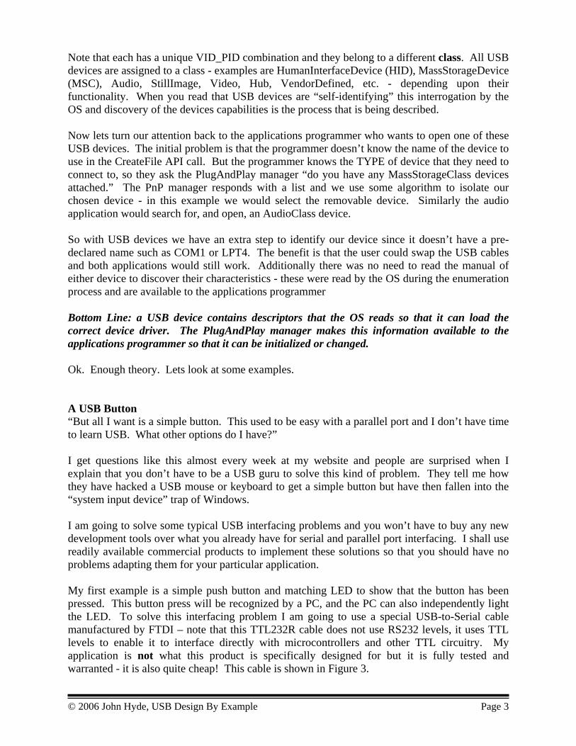
Note that each has a unique VID_PID combination and they belong to a different class. All USB devices are assigned to a class - examples are HumanInterfaceDevice (HID), MassStorageDevice (MSC), Audio, StillImage, Video, Hub, VendorDefined, etc. - depending upon their functionality. When you read that USB devices are “self-identifying” this interrogation by the OS and discovery of the devices capabilities is the process that is being described. Now lets turn our attention back to the applications programmer who wants to open one of these USB devices. The initial problem is that the programmer doesn’t know the name of the device to use in the CreateFile API call. But the programmer knows the TYPE of device that they need to connect to, so they ask the PlugAndPlay manager “do you have any MassStorageClass devices attached.” The PnP manager responds with a list and we use some algorithm to isolate our chosen device - in this example we would select the removable device. Similarly the audio application would search for, and open, an AudioClass device. So with USB devices we have an extra step to identify our device since it doesn’t have a pre-declared name such as COM1 or LPT4. The benefit is that the user could swap the USB cables and both applications would still work. Additionally there was no need to read the manual of either device to discover their characteristics - these were read by the OS during the enumeration process and are available to the applications programmer Bottom Line: a USB device contains descriptors that the OS reads so that it can load the correct device driver. The PlugAndPlay manager makes this information available to the applications programmer so that it can be initialized or changed. Ok. Enough theory. Lets look at some examples. A USB Button “But all I want is a simple button. This used to be easy with a parallel port and I don’t have time to learn USB. What other options do I have?” I get questions like this almost every week at my website and people are surprised when I explain that you don’t have to be a USB guru to solve this kind of problem. They tell me how they have hacked a USB mouse or keyboard to get a simple button but have then fallen into the “system input device” trap of Windows. I am going to solve some typical USB interfacing problems and you won’t have to buy any new development tools over what you already have for serial and parallel port interfacing. I shall use readily available commercial products to implement these solutions so that you should have no problems adapting them for your particular application. My first example is a simple push button and matching LED to show that the button has been pressed. This button press will be recognized by a PC, and the PC can also independently light the LED. To solve this interfacing problem I am going to use a special USB-to-Serial cable manufactured by FTDI – note that this TTL232R cable does not use RS232 levels, it uses TTL levels to enable it to interface directly with microcontrollers and other TTL circuitry. My application is not what this product is specifically designed for but it is fully tested and warranted - it is also quite cheap! This cable is shown in Figure 3.
© 2006 John Hyde, USB Design By Example Page 3
© 2006 John Hyde, USB Design By Example Page 4
Active
Green
Yellow
Orange
Red
Brown
Black
Vbus
Gnd
Insert
or
Active
Green
Yellow
Orange
Red
Brown
Black
Vbus
Gnd
Insert
or
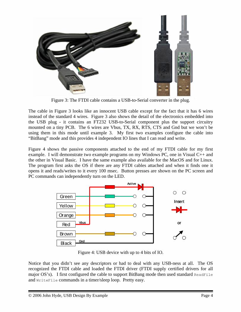
Figure 3: The FTDI cable contains a USB-to-Serial converter in the plug. The cable in Figure 3 looks like an innocent USB cable except for the fact that it has 6 wires instead of the standard 4 wires. Figure 3 also shows the detail of the electronics embedded into the USB plug - it contains an FT232 USB-to-Serial component plus the support circuitry mounted on a tiny PCB. The 6 wires are Vbus, TX, RX, RTS, CTS and Gnd but we won’t be using them in this mode until example 3. My first two examples configure the cable into “BitBang” mode and this provides 4 independent IO lines that I can read and write. Figure 4 shows the passive components attached to the end of my FTDI cable for my first example. I will demonstrate two example programs on my Windows PC, one in Visual C++ and the other in Visual Basic. I have the same example also available for the MacOS and for Linux. The program first asks the OS if there are any FTDI cables attached and when it finds one it opens it and reads/writes to it every 100 msec. Button presses are shown on the PC screen and PC commands can independently turn on the LED.
Figure 4: USB device with up to 4 bits of IO. Notice that you didn’t see any descriptors or had to deal with any USB-ness at all. The OS recognized the FTDI cable and loaded the FTDI driver (FTDI supply certified drivers for all major OS’s). I first configured the cable to support BitBang mode then used standard ReadFile and WriteFile commands in a timer/sleep loop. Pretty easy.

© 2006 John Hyde, USB Design By Example Page 5
1K0
VCC
TXD.0RTS.2RXD.1CTS.3
GND
SCLSDA
INT
10K
10K
10K
330
330
330
330
330
330
330
330
PCA9554
AddressSelect
1K0
VCC
TXD.0RTS.2RXD.1CTS.3
GND
SCLSDA
INT
10K
10K
10K
330
330
330
330
330
330
330
330
PCA9554
AddressSelect
If you don’t like the gauge or the length of the cable you can just purchase the “plug + electronics” and add your own cable and case. The electronics supports 4 IO lines and these can be any combination of buttons and LEDs. Inputting and Outputting Bytes. The first example used the four available signals of the FTDI cable as simple IO lines. This second example uses these lines as an I2C bus and the example program adds an I2C protocol. From the software perspective this just means that I write and read a buffer of bytes rather than single bytes - a small extension to the example software. Most of the software effort was designing and implementing the human interface. From the hardware perspective I add up to 8 I2C IO expanders as shown in Figure 5.
Figure 5: USB device with up to 8 bytes of IO. So, with this cable and a few standard components I can simply access 64 bits of IO - enough for many control panels, system configuration, or even a distributed data gathering system. I have this up and running and I didn’t have to even open the USB spec! All the USB-ness is handled by the device, and the device driver, allowing me to concentrate on my application. Now is a good time to discuss USB power considerations. Power can be drawn from the Vbus line but you must understand the rules. A USB host port is required to supply up to 100mA at 5.0 Volts for any device - mice and keyboards can run off this power. If your device requires more power you are allowed to request up to 500mA once your device is configured. A PC or a powered hub will have no problems supplying this power but an un-powered hub (which I recommend you do not use!) will not be able to do this and this creates user confusion. If your device needs more than 500mA then it should contain its own power source - the USB spec calls this a self-powered device but this is still allowed to request up to 500mA from the bus. At the other end of the scale a device must not consume more that 0.5mA when it is suspended. As a PC is powering down it stops sending signals on USB and devices must interpret no USB activity for 3msec to mean “suspend yourself”. There is no point having a peripheral device powered on if the PC is powered off. A powered down device can have the ability to send a “WakeUp” signal to the PC to bring it back to its powered-on state.

Converting a serial device to USB In this third example I use the FTDI cable in the mode that it was designed for. Figure 6 shows a typical serial device connected to a PC. It has an internal microprocessor or microcontroller that drives an RS232 voltage converter for PC communications and drives custom IO specific to the embedded application. In the center diagram of Figure 6 I have replaced the serial cable with the FTDI cable. This cable drives TTL levels so there is no need for the RS232 voltage converters. We have a problem with the connector however since the industry expects RS232 voltage levels on the 9 pin (or 25 pin) serial connector; I shall deal with this issue in a moment. What impact does changing the cable have on the PC and the application software? The OS will now enumerate a USB device instead of a COM device and will load the FTDI drivers again. These drivers include a Virtual Comport driver - which means that a device called COMxx will be added by the PlugAndPlay manager. So, the application program now opens, say, COM8 rather than COM1 - there are no other changes needed. Now look at the third diagram in Figure 6 - I have moved the FT232 part from the “PC end” of the cable to the “device end” of the cable. This FT232 part replaces the RS232 voltage converter and I replace the serial port connector with a USB B connector (standard size or mini-B). This means that I use a standard USB cable to connect me new device to the PC.
RS232Buffers uC
IO
IOPC
CO
M1
uCIO
IOPC U
SB1
uCIO
IOPC U
SB1
FT232USB-B
???
9-Pin DRS232Buffers uC
IO
IOPC
CO
M1
uCIO
IOPC U
SB1
uCIO
IOPC U
SB1
FT232USB-B
???
9-Pin D
Figure 6: Migrating a serial connection to USB.
© 2006 John Hyde, USB Design By Example Page 6
© 2006 John Hyde, USB Design By Example Page 7
USB
TXRX
FT2232
BA
RS232 Buffers
USB
TXRX
RS23
2 Bu
ffer
s
RS23
2 Bu
ffer
s
FT2232
BA
USB
RXTX
FT2232
BA
RS232 Buffers
USB
TXRX
RS23
2 Bu
ffer
s
RS23
2 Bu
ffer
s
FT2232
BA
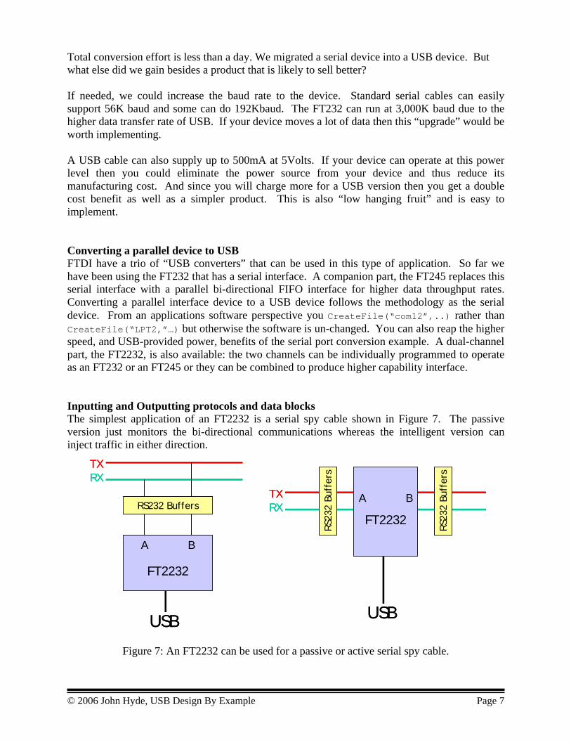
Total conversion effort is less than a day. We migrated a serial device into a USB device. But what else did we gain besides a product that is likely to sell better? If needed, we could increase the baud rate to the device. Standard serial cables can easily support 56K baud and some can do 192Kbaud. The FT232 can run at 3,000K baud due to the higher data transfer rate of USB. If your device moves a lot of data then this “upgrade” would be worth implementing. A USB cable can also supply up to 500mA at 5Volts. If your device can operate at this power level then you could eliminate the power source from your device and thus reduce its manufacturing cost. And since you will charge more for a USB version then you get a double cost benefit as well as a simpler product. This is also “low hanging fruit” and is easy to implement. Converting a parallel device to USB FTDI have a trio of “USB converters” that can be used in this type of application. So far we have been using the FT232 that has a serial interface. A companion part, the FT245 replaces this serial interface with a parallel bi-directional FIFO interface for higher data throughput rates. Converting a parallel interface device to a USB device follows the methodology as the serial device. From an applications software perspective you CreateFile(“com12”,..) rather than CreateFile(“LPT2,”…) but otherwise the software is un-changed. You can also reap the higher speed, and USB-provided power, benefits of the serial port conversion example. A dual-channel part, the FT2232, is also available: the two channels can be individually programmed to operate as an FT232 or an FT245 or they can be combined to produce higher capability interface. Inputting and Outputting protocols and data blocks The simplest application of an FT2232 is a serial spy cable shown in Figure 7. The passive version just monitors the bi-directional communications whereas the intelligent version can inject traffic in either direction.
Figure 7: An FT2232 can be used for a passive or active serial spy cable.
© 2006 John Hyde, USB Design By Example Page 8
FT2232USBRD
TX
TLC7528
A
B
TLC272
WRFT2232USB
RD
TX
TLC7528
A
B
TLC272
WR
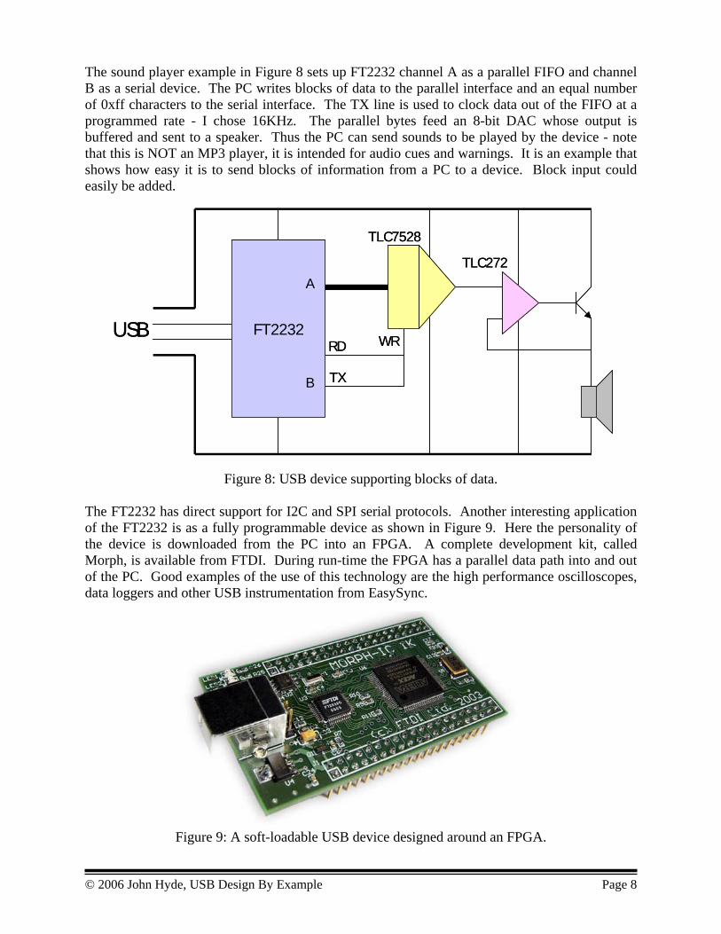
The sound player example in Figure 8 sets up FT2232 channel A as a parallel FIFO and channel B as a serial device. The PC writes blocks of data to the parallel interface and an equal number of 0xff characters to the serial interface. The TX line is used to clock data out of the FIFO at a programmed rate - I chose 16KHz. The parallel bytes feed an 8-bit DAC whose output is buffered and sent to a speaker. Thus the PC can send sounds to be played by the device - note that this is NOT an MP3 player, it is intended for audio cues and warnings. It is an example that shows how easy it is to send blocks of information from a PC to a device. Block input could easily be added.
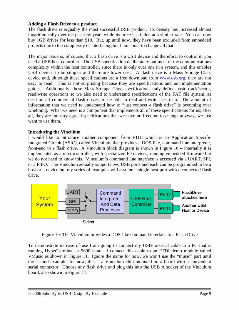
Figure 8: USB device supporting blocks of data. The FT2232 has direct support for I2C and SPI serial protocols. Another interesting application of the FT2232 is as a fully programmable device as shown in Figure 9. Here the personality of the device is downloaded from the PC into an FPGA. A complete development kit, called Morph, is available from FTDI. During run-time the FPGA has a parallel data path into and out of the PC. Good examples of the use of this technology are the high performance oscilloscopes, data loggers and other USB instrumentation from EasySync.
Figure 9: A soft-loadable USB device designed around an FPGA.
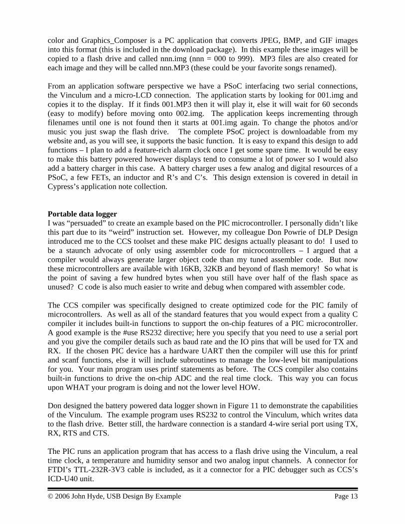
Adding a Flash Drive to a product The flash drive is arguably the most successful USB product. Its density has increased almost logarithmically over the past few years while its price has fallen at a similar rate. You can now buy 1GB drives for less than $10. But, up until now, they have been excluded from embedded projects due to the complexity of interfacing but I am about to change all that! The major issue is, of course, that a flash drive is a USB device and therefore, to control it, you need a USB host controller. The USB specification deliberately put most of the communications complexity within the host controller, since there is only ever one in a system, and this enables USB devices to be simpler and therefore lower cost. A flash drive is a Mass Storage Class device and, although these specifications are a free download from www.usb.org, they are not easy to read. This is not surprising because they are specifications and not implementation guides. Additionally, these Mass Storage Class specifications only define basic track/sector, read/write operations so we also need to understand specifications of the FAT file system, as used on all commercial flash drives, to be able to read and write user data. The amount of information that we need to understand how to “just connect a flash drive” is becoming over whelming. What we need is a component that implements all of these specifications for us; after all, they are industry agreed specifications that we have no freedom to change anyway, we just want to use them. Introducing the Vinculum I would like to introduce another component from FTDI which is an Application Specific Integrated Circuit (ASIC), called Vinculum, that provides a DOS-like, command line interpreter, front-end to a flash drive. A Vinculum block diagram is shown in Figure 10 – internally it is implemented as a microcontroller, with specialized IO devices, running embedded firmware but we do not need to know this. Vinculum’s command line interface is accessed via a UART, SPI, or a FIFO. The Vinculum actually supports two USB ports and each can be programmed to be a host or a device but my series of examples will assume a single host port with a connected flash drive.
Port2
Port1
YourSystem
FlashDriveattaches here
Another USBHost or Device
UART
SPI
FIFO
CommandInterpreterAnd DataProcessor
USB HostController
Select
Port2
Port1
YourSystem
FlashDriveattaches here
Another USBHost or Device
UART
SPI
FIFO
CommandInterpreterAnd DataProcessor
USB HostController
Select
Figure 10: The Vinculum provides a DOS-like command interface to a Flash Drive To demonstrate its ease of use I am going to connect my USB-to-serial cable to a PC that is running HyperTerminal at 9600 baud. I connect this cable to an FTDI demo module called VMusic as shown in Figure 11. Ignore the name for now, we won’t use the “music” part until the second example; for now, this is a Vinculum chip mounted on a board with a convenient serial connector. Choose any flash drive and plug this into the USB A socket of the Vinculum board, also shown in Figure 11.
© 2006 John Hyde, USB Design By Example Page 9

Figure 11: Using our trusty USB-to-Serial cable with a VMusic demo board. The board will sign on and offer a D: > prompt. Now, in HyperTerminal, enter “DIR” and, Hey Presto, the contents of the drive are displayed. Now enter the following commands:
OPW test1 IPA WRF 12 Hello World! CLF test1
These commands first opens a file called “test1” for write, then tells Vinculum that 12 bytes of data are coming. “Hello World!” is the data that is written, and CLF closes the data file. Now remove the flash drive and connect it to your PC, Mac or Linux system and open test1. Notice that the data written by the Vinculum is present. Now edit test1 to add a message “Hello from my PC, Mac or Linux” Now reattach the flash drive to the Vinculum board and enter “RD test1”. Voila, the text is displayed! Now stop and think what we have accomplished. We have written, read and exchanged data files between a PC, Mac or Linux system and an embedded system using a flash drive. We did not have to learn USB, the Mass Storage Class specification or even the FAT file system. It was as easy as entering DOS-like commands on a serial connection. Pretty amazing. The Vinculum powers up in Extended Command mode where all the commands and data are ASCII; some of these commands are summarized in Figure 12. It can be switched into Short Command mode where binary commands and data can be exchanged. The VMusic board only provides access to the UART connection but this will be enough for my first set of examples. The Vinculum is also available in an OEM 24 pin DIP and this additionally provides access to the SPI port, the parallel port FIFO and the other USB port.
© 2006 John Hyde, USB Design By Example Page 10

Directory Operations DIR Lists the current directory MKD <name> Creates a new directory <name> in the current directory DLD <name> Deletes the directory <name> from the current directory CD <name> The current directory is changed to the new directory <name> CD .. Move up one directory level File operations RD <name> Read file <name>. This will return the entire file OPR <name> Opens file <name> for reading with ‘RDF’ RDF <size> Reads <size> bytes of data from the current file OPW <name> Opens file <name> for writing with ‘WRF’ WRF <size> Writes <size> bytes of data to the end of the current open file CLF <name> Closes file <name> for writing DLF <name> This will delete the file from the current directory and free up disk
space VPF <name> Play an MP3 file. Sends file to SPI interface then returns REN <n1><n2> Rename a file or directory Management Commands SCS Switch to the short command set ECS Switch to the extended command set IPA Input data values in ASCII IPH Input data values in Hex SUD Suspend the disk when not in use to conserve power. The disk will
be woken up automatically when a disk command is sent to it. WKD Wake Disk and do not put it into suspend when not in use SUM Suspend Monitor and stop clocks FWV Get Firmware Versions FS Returns free space in bytes on disk
Figure 12: This table shows some of the monitor’s DOS-like commands. There are two types of project suitable for a Vinculum – data distribution and data collection and I have examples of each category. Typically, data to be distributed is created on a PC using specialist tools and then copied onto a flash drive; an embedded system then accesses this information and presents it to a user or a machine. My example is a small JPEG viewer and MP3 player – something that we would take on a business trip and that plays back images and sounds of our family, or our favorite music. If I had used a larger display I would have called this an “active photo frame” (it is on my TODO list!). My data collection example is a portable data logger that collects field data for later analysis by a PC. In both cases an application microcontroller is used to drive the Vinculum (it is a peripheral device) and other circuitry. I am confident that you can dream up many more applications for this easy-to-use part.
© 2006 John Hyde, USB Design By Example Page 11

JPEG viewer and MPEG player I chose a Cypress PSoC for the target microcontroller since it has firmware-configurable hardware that allows me to solve a wide range of problems with a single device. I develop and debug using a “high-end” PSoC device that has ample analog and digital resources then, near project completion, I can select a lower cost device within the same family. For the first example I shall use the Cypress PSoC Evaluation board and this is shown in Figure 13 with the VMusic board and a 1.5” x 1.5” Micro-LCD display already attached to the breadboard area.
Figure 13: This example was developed and debugged using a PSoC development system.
In summary I have a PSoC that reads image files off a flash drive using commands sent to the Vinculum monitor, the PSoC then displays this image. If a matching MP3 file is also present on the flash drive then I command the Vinculum to play it – this could be music or a person talking. A PC is used to create the image and MP3 files and these are copied onto the flash drive. The PSoC/Vinculum-based player then “runs the show.” A JPEG viewer and MPEG player is the base example but an interactive display that could be used in stores, museums, product demonstrations, art galleries, etc. is a straightforward design extension. A series of flash drives in English, Spanish, Japanese, etc. could be used to create a more universal solution. Another beneficial aspect of a PSoC-based design is that Cypress has over a hundred applications notes that describe building blocks that can be used within your own design. The PSoC could scan buttons, which would use CapSense technology, and the application program would use these button inputs to navigate through images / MP3 files.
Additionally the PSoC could support a touch screen using a few of its configurable analog and digital blocks. This could be a simple resistive screen overlay or a more reliable CapSense implementation. The size of the graphical display determines the complexity and choice of the PSoC. Since this is a paper about embedded flash drive applications I chose the simplest display to implement here and I will cover interfacing to a larger display in a future article. I found a serial-interface, micro-LCD at www.dontronics-shop.com and was very impressed with ease of use of these 128x128 color displays. These 1.5” x 1.5” displays are not expensive – you should get some and experiment with them. I am sure that you will soon find many uses for them, just as I did. I personally found the OLED displays much better to look at when compared with the LCD displays but the firmware to drive the both displays is identical. The micro-LCD module is a very capable subsystem that supports graphics rending and several fonts. My example uses about 5% of its capability as I just download images to it. These images are 128x128 by 16-bit
© 2006 John Hyde, USB Design By Example Page 12
color and Graphics_Composer is a PC application that converts JPEG, BMP, and GIF images into this format (this is included in the download package). In this example these images will be copied to a flash drive and called nnn.img (nnn = 000 to 999). MP3 files are also created for each image and they will be called nnn.MP3 (these could be your favorite songs renamed). From an application software perspective we have a PSoC interfacing two serial connections, the Vinculum and a micro-LCD connection. The application starts by looking for 001.img and copies it to the display. If it finds 001.MP3 then it will play it, else it will wait for 60 seconds (easy to modify) before moving onto 002.img. The application keeps incrementing through filenames until one is not found then it starts at 001.img again. To change the photos and/or music you just swap the flash drive. The complete PSoC project is downloadable from my website and, as you will see, it supports the basic function. It is easy to expand this design to add functions – I plan to add a feature-rich alarm clock once I get some spare time. It would be easy to make this battery powered however displays tend to consume a lot of power so I would also add a battery charger in this case. A battery charger uses a few analog and digital resources of a PSoC, a few FETs, an inductor and R’s and C’s. This design extension is covered in detail in Cypress’s application note collection. Portable data logger I was “persuaded” to create an example based on the PIC microcontroller. I personally didn’t like this part due to its “weird” instruction set. However, my colleague Don Powrie of DLP Design introduced me to the CCS toolset and these make PIC designs actually pleasant to do! I used to be a staunch advocate of only using assembler code for microcontrollers – I argued that a compiler would always generate larger object code than my tuned assembler code. But now these microcontrollers are available with 16KB, 32KB and beyond of flash memory! So what is the point of saving a few hundred bytes when you still have over half of the flash space as unused? C code is also much easier to write and debug when compared with assembler code. The CCS compiler was specifically designed to create optimized code for the PIC family of microcontrollers. As well as all of the standard features that you would expect from a quality C compiler it includes built-in functions to support the on-chip features of a PIC microcontroller. A good example is the #use RS232 directive; here you specify that you need to use a serial port and you give the compiler details such as baud rate and the IO pins that will be used for TX and RX. If the chosen PIC device has a hardware UART then the compiler will use this for printf and scanf functions, else it will include subroutines to manage the low-level bit manipulations for you. Your main program uses printf statements as before. The CCS compiler also contains built-in functions to drive the on-chip ADC and the real time clock. This way you can focus upon WHAT your program is doing and not the lower level HOW. Don designed the battery powered data logger shown in Figure 11 to demonstrate the capabilities of the Vinculum. The example program uses RS232 to control the Vinculum, which writes data to the flash drive. Better still, the hardware connection is a standard 4-wire serial port using TX, RX, RTS and CTS. The PIC runs an application program that has access to a flash drive using the Vinculum, a real time clock, a temperature and humidity sensor and two analog input channels. A connector for FTDI’s TTL-232R-3V3 cable is included, as it a connector for a PIC debugger such as CCS’s ICD-U40 unit.
© 2006 John Hyde, USB Design By Example Page 13
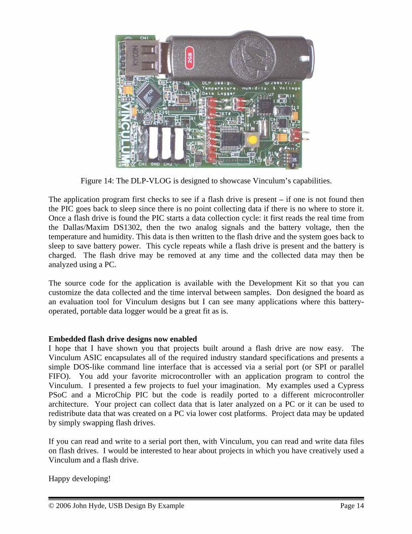
Figure 14: The DLP-VLOG is designed to showcase Vinculum’s capabilities. The application program first checks to see if a flash drive is present – if one is not found then the PIC goes back to sleep since there is no point collecting data if there is no where to store it. Once a flash drive is found the PIC starts a data collection cycle: it first reads the real time from the Dallas/Maxim DS1302, then the two analog signals and the battery voltage, then the temperature and humidity. This data is then written to the flash drive and the system goes back to sleep to save battery power. This cycle repeats while a flash drive is present and the battery is charged. The flash drive may be removed at any time and the collected data may then be analyzed using a PC. The source code for the application is available with the Development Kit so that you can customize the data collected and the time interval between samples. Don designed the board as an evaluation tool for Vinculum designs but I can see many applications where this battery-operated, portable data logger would be a great fit as is. Embedded flash drive designs now enabled I hope that I have shown you that projects built around a flash drive are now easy. The Vinculum ASIC encapsulates all of the required industry standard specifications and presents a simple DOS-like command line interface that is accessed via a serial port (or SPI or parallel FIFO). You add your favorite microcontroller with an application program to control the Vinculum. I presented a few projects to fuel your imagination. My examples used a Cypress PSoC and a MicroChip PIC but the code is readily ported to a different microcontroller architecture. Your project can collect data that is later analyzed on a PC or it can be used to redistribute data that was created on a PC via lower cost platforms. Project data may be updated by simply swapping flash drives. If you can read and write to a serial port then, with Vinculum, you can read and write data files on flash drives. I would be interested to hear about projects in which you have creatively used a Vinculum and a flash drive. Happy developing!
© 2006 John Hyde, USB Design By Example Page 14