
How to Use Player/Stageplayerstage.sourceforge.net/doc/playerstage_instructions_2.0.pdf · These...
70
How to Use Player/Stage Jennifer Owen July 10, 2009 This document is intended as a guide for anyone learning Player/Stage for the first time. It explains the process of setting up a new simulation environment and how to then make your simulation do something, using a case study along the way. Whilst it is aimed at Player/Stage users, those just wishing to use Player on their robot may also find sections of this document useful (particularly the parts about coding with Player). If you have any questions about using Player/Stage there is a guide to getting help from the Player comunity here: http://playerstage.sourceforge.net/wiki/Getting_help 1
Transcript of How to Use Player/Stageplayerstage.sourceforge.net/doc/playerstage_instructions_2.0.pdf · These...
How to Use Player/Stage
Jennifer Owen
July 10, 2009
This document is intended as a guide for anyone learning Player/Stage forthe first time. It explains the process of setting up a new simulation environmentand how to then make your simulation do something, using a case study alongthe way. Whilst it is aimed at Player/Stage users, those just wishing to usePlayer on their robot may also find sections of this document useful (particularlythe parts about coding with Player).
If you have any questions about using Player/Stage there is a guide to gettinghelp from the Player comunity here:
http://playerstage.sourceforge.net/wiki/Getting_help
1

Contents
1 Introduction 31.1 A Note on Installing Player/Stage . . . . . . . . . . . . . . . . . 3
2 The Basics 32.1 Important File Types . . . . . . . . . . . . . . . . . . . . . . . . 32.2 Interfaces, Drivers and Devices . . . . . . . . . . . . . . . . . . . 4
3 Building a World 53.1 Building an Empty World . . . . . . . . . . . . . . . . . . . . . . 7
3.1.1 Models . . . . . . . . . . . . . . . . . . . . . . . . . . . . 83.1.2 Describing the Player/Stage Window . . . . . . . . . . . . 113.1.3 Making a Basic Worldfile . . . . . . . . . . . . . . . . . . 12
3.2 Building a Robot . . . . . . . . . . . . . . . . . . . . . . . . . . . 133.2.1 Sensors and Devices . . . . . . . . . . . . . . . . . . . . . 133.2.2 An Example Robot . . . . . . . . . . . . . . . . . . . . . . 17
3.3 Building Other Stuff . . . . . . . . . . . . . . . . . . . . . . . . . 27
4 Writing a Configuration (.cfg) File 314.1 Device Addresses - key:host:robot:interface:index . . . . . . . . . 334.2 Putting the Configuration File Together . . . . . . . . . . . . . . 34
5 Getting Your Simulation To Run Your Code 365.1 Connecting to the Server and Proxies With Your Code . . . . . . 37
5.1.1 Setting Up Connections: an Example. . . . . . . . . . . . 395.2 Interacting with Proxies . . . . . . . . . . . . . . . . . . . . . . . 40
5.2.1 Position2dProxy . . . . . . . . . . . . . . . . . . . . . . . 405.2.2 SonarProxy . . . . . . . . . . . . . . . . . . . . . . . . . . 425.2.3 LaserProxy . . . . . . . . . . . . . . . . . . . . . . . . . . 435.2.4 RangerProxy . . . . . . . . . . . . . . . . . . . . . . . . . 435.2.5 BlobfinderProxy . . . . . . . . . . . . . . . . . . . . . . . 445.2.6 GripperProxy . . . . . . . . . . . . . . . . . . . . . . . . . 455.2.7 SimulationProxy . . . . . . . . . . . . . . . . . . . . . . . 465.2.8 General Useful Commands . . . . . . . . . . . . . . . . . 47
5.3 Using Proxies: A Case Study . . . . . . . . . . . . . . . . . . . . 475.3.1 The Control Architecture . . . . . . . . . . . . . . . . . . 485.3.2 Beginning the Code . . . . . . . . . . . . . . . . . . . . . 485.3.3 Wander . . . . . . . . . . . . . . . . . . . . . . . . . . . . 495.3.4 Obstacle Avoidance . . . . . . . . . . . . . . . . . . . . . 515.3.5 Move To Item . . . . . . . . . . . . . . . . . . . . . . . . . 525.3.6 Collect Item . . . . . . . . . . . . . . . . . . . . . . . . . . 54
5.4 Simulating Multiple Robots . . . . . . . . . . . . . . . . . . . . . 56
6 Useful Links 58
7 Appendices 59
2

1 Introduction
Player/Stage is a robot simulation tool, it comprises of one program, Player,which is a Hardware Abstraction Layer. That means that it talks to the bits ofhardware on the robot (like a claw or a camera) and lets you control them withyour code, meaning you don’t need to worry about how the various parts of therobot work. Stage is a plugin to Player which listens to what Player is tellingit to do and turns these instructions into a simulation of your robot. It alsosimulates sensor data and sends this to Player which in turn makes the sensordata available to your code.
A simulation then, is composed of three parts:
• Your code. This talks to Player.
• Player. This takes your code and sends instructions to a robot. From therobot it gets sensor data and sends it to your code.
• Stage. Stage interfaces with Player in the same way as a robot’s hardwarewould. It receives instructions from Player and moves a simulated robotin a simulated world, it gets sensor data from the robot in the simulationand sends this to Player.
Together Player and Stage are called Player/Stage, and they make a simulationof your robots.
These instructions will be focussing on how to use Player/Stage to makea simulation, but hopefully this will still be a useful resource for anyone justusing Player (which is the same thing but on a real robot, without any simulationsoftware).
1.1 A Note on Installing Player/Stage
Instructions on how to install Player/Stage onto your computer aren’t really thefocus of this document. It is very difficult though. If you’re lucky the install willwork first time but there are a lot of dependencies which may need installing.In Linux there are the install programmes “synaptic” or “aptitude” which willinstall a package and also get its dependencies, but these aren’t common to allLinux distributions. There is another install program called “apt-get” but thiswon’t install dependencies for you. For computers running Ubuntu there is areasonable set of instructions here:
http://www.control.aau.dk/~tb/wiki/index.php/Installing_Player_and_Stage_in_Ubuntu
Alternatively, you try the suggestions on the Player “getting help” page:
http://playerstage.sourceforge.net/wiki/Getting_help
2 The Basics
2.1 Important File Types
In Player/Stage there are 3 kinds of file that you need to understand to getgoing with Player/Stage:
3

• a .world file
• a .cfg (configuration) file
• a .inc (include) file
The .world file tells Player/Stage what things are available to put in the world.In this file you describe your robot, any items which populate the world andthe layout of the world. The .inc file follows the same syntax and format of a.world file but it can be included. So if there is an object in your world thatyou might want to use in other worlds, such as a model of a robot, putting therobot description in a .inc file just makes it easier to copy over, it also meansthat if you ever want to change your robot description then you only need todo it in one place and your multiple simulations are changed too.
The .cfg file is what Player reads to get all the information about the robotthat you are going to use.This file tells Player which drivers it needs to use inorder to interact with the robot, if you’re using a real robot these drivers arebuilt in to Player1, alternatively, if you want to make a simulation, the driveris always Stage (this is how Player uses Stage in the same way it uses a robot:it thinks that it is a hardware driver and communicates with it as such). The.cfg file tells Player how to talk to the driver, and how to interpret any datafrom the driver so that it can be presented to your code. Items described in the.world file should be described in the .cfg file if you want your code to be able tointeract with that item (such as a robot), if you don’t need your code to interactwith the item then this isn’t necessary. The .cfg file does all this specificationusing interfaces and drivers, which will be discussed in the following section.
2.2 Interfaces, Drivers and Devices
• Drivers are pieces of code that talk directly to hardware. These are builtin to Player so it is not important to know how to write these as you beginto learn Player/Stage. The drivers are specific to a piece of hardware so,say, a laser driver will be different to a camera driver, and also differentto a driver for a different brand of laser. This is the same as the way thatdrivers for graphics cards differ for each make and model of card. Driversproduce and read information which conforms to an “interface”.
• Interfaces are a set way for a driver to send and receive information fromPlayer. Like drivers, interfaces are also built in to Player and there is a biglist of them in the Player manual2. They specify the syntax and semanticsof how drivers and Player interact.
• A device is a driver that is bound to an interface so that Player can talkto it directly. This means that if you are working on a real robot thatyou can interact with a real device (laser, gripper, camera etc) on the realrobot, in a simulated robot you can interact with their simulations.
The official documentation actually describes these 3 things quite well withan example.
1Or you can download or write your own drivers, but I’m not going to talk about how todo this here.
2http://playerstage.sourceforge.net/doc/Player-2.1.0/player/group interfaces.html
4

Consider the laser interface. This interface defines a format inwhich a planar range-sensor can return range readings (basically alist of ranges, with some meta-data). The laser interface is just that:an interface. You can’t do anything with it.
Now consider the sicklms200 driver. This driver controls a SICKLMS200, which is particular planar range sensor that is popularin mobile robot applications. The sicklms200 driver knows how tocommunicate with the SICK LMS200 over a serial line and retrieverange data from it. But you don’t want to access the range datain some SICK-specific format. So the driver also knows how totranslate the retrieved data to make it conform to the format definedby the laser interface.
The sicklms200 driver can be bound to the laser interface . . . tocreate a device, which might have the following address:
localhost:6665:laser:0The fields in this address correspond to the entries in the player devaddr t
structure: host, robot, interface, and index. The host and robotfields (localhost and 6665) indicate where the device is located. Theinterface field indicates which interface the device supports, and thushow it can be used. Because you might have more than one laser,the index field allows you to pick among the devices that supportthe given interface and are located on the given host:robot Otherlasers on the same host:robot would be assigned different indexes.
The last paragraph there gets a bit technical, but don’t worry. Player talks toparts of the robot using ports (the default port is 6665), if you’re using Stagethen Player and Stage communicate through these ports (even if they’re runningon the same computer). All this line does is tell Player which port to listen toand what kind of data to expect. In the example it’s laser data which is beingtransmitted on port 6665 of the computer that Player is running on (localhost).You could just as easily connect to another computer by using its IP addressinstead of “localhost”. The specifics of writing a device address in this way willbe described in section 4.
3 Building a World
First we will run a world and configuration file that comes bundled with Stage.In your bash shell navigate to the Stage/worlds folder, by default (in Linux atleast) this is /usr/local/share/stage/worlds. Once in the correct folder type thefollowing command to run the “simple world” that comes with Player/Stage:
player simple.cfg
Assuming Player/Stage is installed properly you should now have a window openwhich looks figure 1. At this stage you can drag and drop the robot around itsworld with your mouse, but you can also tele-operate the robot using the PlayerViewer program. In a separate terminal whilst the Player/Stage simulationwindow is still open, type:
playerv --position2d --laser
5

Figure 1: The simple.cfg world after being run
6

Figure 2: The simple.cfg world seen with Player Viewer
Figure 3: How to Remote Control (tele-operate) the Stage Robot
The --position2d and --laser options tell the playerv (Player Viewer) pro-gram that you want to look at the positional data and the laser data that isavailable to the robot. This should open a window which looks like figure 2.
To be able to remote control the robot you click Device → position2d:0 →Command as shown in figure 3. A cross-hair should appear over the robot inthe Player Viewer window, which if you drag around will cause the robot tomove in the Player/Stage simulation (figure 1).
3.1 Building an Empty World
As you can see in section 3, when we tell Player to build a world we only give itthe .cfg file as an input. This .cfg file needs to tell us where to find our .worldfile, which is where all the items in the simulation are described. To explain howto build a Stage world containing nothing but walls we will use an example.To start building an empty world we need a .cfg file. First create a documentcalled empty.cfg and copy the following code into it:
driver(
name "stage"plugin "libstageplugin"
provides ["simulation:0" ]
7

# load the named file into the simulatorworldfile "empty.world"
)
The configuration file syntax is described in section 4, but basically what ishappening here is that your configuration file is telling Player that there is adriver called stage in the libstageplugin library, and this will give Playerdata which conforms to the simulation interface. To build the simulationPlayer needs to look in the worldfile called empty.world which is stored in thesame folder as this .cfg. If it was stored elsewhere you would have to include afilepath, for example ./worlds/empty.world. Lines that begin with the hashsymbol (#) are comments. When you build a simulation, any simulation, inStage the above chunk of code should always be the first thing the configurationfile says. Obviously the name of the worldfile should be changed depending onwhat you called it though.
Now a basic configuration file has been written, it is time to tell Player/Stagewhat to put into this simulation. This is done in the .world file.
3.1.1 Models
A worldfile is basically just a list of models that describes all the stuff in thesimulation. This includes the basic environment, robots and other objects. Thebasic type of model is called “model”, and you define a model using the followingsyntax:
define model_name model(
# parameters)
This tells Player/Stage that you are defining a model which you have calledmodel_name, and all the stuff in the round brackets are parameters of themodel. To begin to understand Player/Stage model parameters, let’s look atthe map.inc file that comes with Stage, this is used to describe the basic envi-ronment in the simulation (e.g. walls the robots can bump into):
define map model(
# sombre, sensible, artisticcolor "black"
# most maps will need a bounding boxboundary 1
gui_nose 1gui_grid 1gui_movemask 0gui_outline 0
fiducial_return 0gripper_return 0
8

)
We can see from the first line that they are defining a model called map.
• color: Tells Player/Stage what colour to render this model, in this caseit is going to be black.
• boundary: Whether or not there is a bounding box around the model.This is an example of a binary parameter, which means the if the numbernext to it is 0 then it is false, if it is 1 or over then it’s true. So here we DOhave a bounding box around our “map” model so the robot can’t wanderout of our map.
• gui_nose: this tells Player/Stage that it should indicate which way themodel is facing. Figure 4 shows the difference between a map with a noseand one without.
• gui_grid: this will superimpose a grid over the model. Figure 5 shows amap with a grid.
• gui_movemask: this indicates whether it should be possible to drag anddrop the model. Here it is 0, so you cannot move the map model oncePlayer/Stage has been run. In section 3 when the Player/Stage examplesimple.cfg was run it was possible to drag and drop the robot becauseits gui_movemask variable was set to 1.
• gui_outline: indicates whether or not the model should be outlined.This makes no difference to a map, but it can be useful when makingmodels of items within the world.
• fiducial_return: any parameter of the form some sensor return de-scribes how that kind of sensor should react to the model. “Fiducial”is a kind of robot sensor which will be described later in section 3.2.1.Setting fiducial_return to 0 means that the map cannot be detected bya fiducial sensor.
• gripper_return: Like fiducial_return, gripper_return tells Player/Stagethat your model can be detected by the relevant sensor, ie it can be grippedby a gripper. This parameter also indicates whether the model can bepushed. Here gripper_return is set to 0 so the map cannot be pushedby a robot and it cannot be gripped by a gripper.
To make use of the map.inc file we put the following code into our worldfile:
include "map.inc"
This inserts the map.inc file into our world file where the include line is. Thisassumes that your worldfile and map.inc file are in the same folder, if they arenot then you’ll need to include the filepath in the quotes. Once this is done wecan modify our definition of the map model to be used in the simulation. Forexample:
9

Figure 4: The left picture shows an empty map without a nose. The rightpicture shows the same map with a nose to indicate orientation, this is thehorizontal line from the centre of the map to the right, it shows that the mapis actually facing to the right.
Figure 5: An empty map with gui grid enabled. With gui grid disabled thiswould just be an empty white square.
10

Figure 6: The left image is our ”helloworld.png” bitmap, the right image is whatPlayer/Stage interprets that bitmap as. The black areas are walls, the robotcan move everywhere else.
map(
bitmap "bitmaps/helloworld.png"size [12 5]
)
What this means is that we are using the model “map”, and making some extradefinitions; both “bitmap” and “size” are parameters of a Player/Stage model.Here we are telling Player/Stage that we defined a bunch of parameters for atype of model called “map” (contained in map.inc) and now we’re using this“map” model definition and adding a few extra parameters.
• bitmap: this is the filepath to a bitmap, which can be type bmp, jpeg, gifor png. Black areas in the bitmap tell the model what shape to be, non-black areas are not rendered, this is illustrated in figure 6. In the map.incfile we told the map that its “color” would be black. This parameter doesnot affect how the bitmaps are read, Player/Stage will always look forblack in the bitmap, the “color” parameter just alters what colour themap is rendered in the simulation.
• size: This is the size in metres of the simulation. All sizes you give inthe world file are in metres, and they represent the actual size of things.If you have 3m x 4m robot testing arena which you want to simulate thenthe size here is [3.0 4.0]. The first number is the size in the x dimension,the second is the y dimension.
A full list of model parameters and their descriptions can be found in theofficial Stage manual3. Most of the useful parameters have already been de-scribed here, however there are a few other types of model which are relevantto building simulations of robots, these will be described later in section 3.2.
3.1.2 Describing the Player/Stage Window
The worldfile also can be used to describe the simulation window that Player/Stagecreates. Player/Stage will automatically make a window for the simulation if
3http://playerstage.sourceforge.net/doc/stage-3.0.1/group model.html
11
you don’t put any window details in the worldfile, however, it is often usefulto put this information in anyway. This prevents a large simulation from beingtoo big for the window, or to increase or decrease the size of the simulation.
Like a model, a window is an inbuilt, high-level entity with lots of parameters.Unlike models though, there can be only one window in a simulation and onlya few of its parameters are really needed. The simulation window is describedwith the following syntax:
window(
parameters...)
The two most important parameters for the window are size and scale.
• size: This is the size the simulation window will be in pixels. You needto define both the width and height of the window using the followingsyntax: size [width height].
• scale: This is how many metres of the simulated environment each pixelshows. The bigger this number is, the smaller the simulation becomes.The optimum value for the scale is map size
window size and it should be roundedupwards slightly so the simulation is a little smaller than the window it’sin.
A full list of window parameters can be found in the Stage manual under“WorldGUI”4.
3.1.3 Making a Basic Worldfile
We have already discussed the basics of worldfile building: models and thewindow. There are just a few more parameters to describe which don’t belongin either a model or a window description which should be defined and then theworldfile can be built.
• size: At this level this represents how big, in metres, the whole simula-tion environment will be. This is completely separate from the map sizebecause it could be larger and there might be several different maps run-ning in the same simulation (so more than one simulation could be run atonce). Generally though this just needs to be the same as the map size.This parameter must be included in the worldfile otherwise the simulationwon’t work.
• interval_sim: This is how many simulated milliseconds there are be-tween each update of the simulation window, the default is 100 millisec-onds.
• interval_real: This is how many real milliseconds there are betweeneach update of the simulation window. Balancing this parameter and theinterval\_sim parameter controls the speed of the simulation. Again, thedefault value is 100 milliseconds, both these interval parameter defaultsare fairly sensible, so it’s not always necessary to redefine them.
4http://playerstage.sourceforge.net/doc/stage-3.0.1/group worldgui.html
12

The Stage manual contains a list of the high-level worldfile parameters5.Finally, we are able to write a worldfile!
include "map.inc"
# size of the whole simulationsize [15 15]
# configure the GUI windowwindow(
size [ 700.0 700.0 ]# 15/700 rounded up a bit
scale 0.025)
# load an environment bitmapmap(
bitmap "bitmaps/cave.png"size [15 15]
)
If we save the above code as empty.world (correcting any filepaths if necessary)we can run its corresponding empty.cfg file (see section 3.1) to get the simulationshown in figure 7.
3.2 Building a Robot
In Player/Stage a robot is just a slightly advanced kind of model, all the pa-rameters described in section 3.1.1 can still be applied.
3.2.1 Sensors and Devices
There are six built-in kinds of model that help with building a robot, they areused to define the sensors and actuators that the robot has. These are associatedwith a set of model parameters which define by which sensors the model canbe detected (these are the _returns mentioned earlier). Each of these built inmodels acts as an interface (see section 2.2) between the simulation and Player.If your robot has one of these kinds of sensor on it, then you need to use therelevant model to describe the sensor, otherwise Stage and Player won’t be ableto pass the data between each other. It is possible to write your own interfaces,but the stuff already included in Player/Stage should be sufficient for mostpeople’s needs. A full list of interfaces that Player supports can be found inthe Player manual6 although only the following are supported by the currentdistribution of Stage (version 3.0.1). Unless otherwise stated, these models usethe Player interface that shares its name:
5http://playerstage.sourceforge.net/doc/stage-3.0.1/group world.html6http://playerstage.sourceforge.net/doc/Player-2.1.0/player/group interfaces.html
13

Figure 7: Our Empty World.
camera 7 The camera model adds a camera to the robot model and allowsyour code to interact with the simulated camera. The camera parameters areas follows:
• resolution [x y]: the resolution, in pixels, of the camera’s image.
• range [min max]: the minimum and maximum range that the cameracan detect
• fov [x y]: the field of view of the camera in degrees.
• pantilt [pan tilt]: the horizontal angle the camera can move through(pan) and the vertical angle (tilt). So for instance pantilt [90 20] al-lows the camera to move 45◦ left and 45◦ right and 10◦ up and 10◦ down.
blobfinder 8 This simulates colour detection software that can be run onthe image from the robot’s camera. It is not necessary to include a model ofthe camera in your description of the robot if you want to use a blobfinder,the blobfinder will work on its own. The blobfinder can only find a model if itsblob_return parameter is true. The parameters for the blobfinder are describedin the Stage manual, but the most useful ones are here:
• colors_count <int>: the number of different colours the blobfinder candetect
7http://playerstage.sourceforge.net/doc/stage-3.0.1/group model camera.html8http://playerstage.sourceforge.net/doc/stage-3.0.1/group model blobfinder.html
14

• colors [ ]: the names of the colours it can detect. This is given tothe blobfinder definition in the form ["black" "blue" "cyan"]. Thesecolour names are from the built in X11 colour database rgb.txt. This isbuilt in to Linux.9
• image [x y]: the size of the image from the camera, in pixels.
• range <float>: The maximum range that the camera can detect, in me-tres.
• fov <float>: field of view of the blobfinder in RADIANS.
It is important to note that the syntax for the blobfinder model is different inStage versions 2.X.X and 3.X.X. The above parameters are specific to Stage3.X.X, in Stage 2.X.X they have different names but do the same thing:
• channel_count <int>: same as colors count.
• channels [ ]: same as colors [ ].
• image [x y]: same as in Stage 3.X.X.
• range_max <float>: same as range
• ptz [pan_angle tilt_angle zoom_angle]: controls the areas that thecamera can look at. This works like pantilt of the camera model, thezoom_angle is the field of view in DEGREES.
Additionally, in Stage 2.X.X blobfinder is a child of a deprecated model calledptz. All this basically means is that when you define your blobfinder model youneed to use this syntax instead:
define model_name ptz(
blobfinder(
# parameters)
)
fiducialfinder 10 A fiducial is a fixed point in an image, so the fiducial findersimulates image processing software that locates fixed points in an image. Thefiducialfinder is able to locate objects in the simulation whose fiducial_returnparameter is set to true. Stage also allows you to specify different types offiducial using the fiducial_key parameter of a model. This means that youcan make the robots able to tell the difference between different fiducials bywhat key they transmit. The fiducial finder and the concept of fiducial_keysis properly explained in the Stage manual.
9rgb.txt can normally be found at /usr/share/X11/rgb.txt assuming it’s properly installed,alternatively a Google search for “rgb.txt” will give you the document.
10http://playerstage.sourceforge.net/doc/stage-3.0.1/group model fiducial.html
15

ranger 11 This simulates any kind of obstacle detection device (e.g. sonarsor infra-red sensors). These can locate models whose ranger_return is true.Using a ranger model you can define any number of ranger devices and applythem all to a single robot. Unlike the other types of model this doesn’t use theinterface with its name but instead the sonar interface, there is more aboutthis in section 4.2. The parameters for the ranger model and their inputs aredescribed in the Stage manual, but basically:
• scount <int>: The number of ranger sensors in this ranger model
• spose[ranger_number] [x y yaw]: Tells the simulator where the rangersare placed around the robot. How to write the [x y yaw] data is explainedin section 3.2.2.
• ssize [x y]: how big the sensors are.
• sview [min max fov]: defines the maximum and minimum distancesthat can be sensed and also the field of view in degrees.
laser 12 A laser is a special case of ranger sensor which only allows one ranger(so there’s none of the scount, spose stuff), but it has a very large field of view.If a model has its laser_return parameter enabled then a laser can detect it.Details about laser parameters can be found in the Stage manual, however themost useful parameters are:
• range_min: The minimum range of the laser.
• range_max: the maximum range of the laser.
• fov: the field of view of the laser. In Stage 3.X.X this is in radians, inStage 2.X.X it is in degrees.
gripper 13 The gripper model is a simulation of the gripper you get on aPioneer robot.14 If you put a gripper on your robot model it means that yourrobot is able to pick up objects and move them around within the simulation.The online Stage manual says that grippers are deprecated in Stage 3.X.X,however this is not actually the case and grippers are very useful if you wantyour robot to be able to manipulate and move items. The parameters you canuse to customise the gripper model are:
• size [x y]: The x and y dimensions of the gripper.
• pose [x y yaw]: Where the gripper is placed on the robot.11http://playerstage.sourceforge.net/doc/stage-3.0.1/group model ranger.html12http://playerstage.sourceforge.net/doc/stage-3.0.1/group model laser.html13http://playerstage.sourceforge.net/doc/Stage-2.0.0/group model gripper.html14The Pioneer grippers looks like a big block on the front of the robot with two big sliders
that close around an object.
16

position 15 The position model simulates the robot’s odometry, this is whenthe robot keeps track of where it is by recording how many times its wheels spinand the angle it turns. This robot model is the most important of all because itallows the robot model to be embodied in the world, meaning it can collide withanything which has its obstacle_return parameter set to true. The positionmodel uses the position2d interface, which is essential for Player because ittells Player where the robot actually is in the world. The most useful parametersof the position model are:
• drive: Tells the odometry how the robot is driven. This is usually “diff”which means the robot is controlled by changing the speeds of the left andright wheels independently. Other possible values are “car” which meansthe robot uses a velocity and a steering angle, or “omni” which means itcan control how it moves along the x and y axes of the simulation.
• localization: tells the model how it should record the odometry “odom”if the robot calculates it as it moves along or “gps” for the robot to haveperfect knowledge about where it is in the simulation.
• odom_error [x y angle]: The amount of error that the robot will makein the odometry recordings.
• mass <int>: How heavy the robot is.
3.2.2 An Example Robot
To demonstrate how to build a model of a robot in Player/Stage we will buildour own example. First we will describe the physical properties of the robot,such as size, shape and mass. Then we will add sensors onto it so that it caninteract with its environment.
The Robot’s Body Let’s say we want to model a rubbish collecting robotcalled “Bigbob”. The first thing we need to do is describe its basic shape, to dothis you need to know your robot’s dimensions in metres. Figure 8 shows thebasic shape of Bigbob drawn onto some cartesian coordinates, the coordinatesof the corners of the robot have been recorded. We can then build this modelusing the polygons model parameter16:
define bigbob position(
# the shape of Bigbobpolygons 1polygon[0].points 6polygon[0].point[0] [0 0]polygon[0].point[1] [0 1]polygon[0].point[2] [0.75 1]polygon[0].point[3] [1 0.75]polygon[0].point[4] [1 0.25]
15http://playerstage.sourceforge.net/doc/stage-3.0.1/group model position.html16In this example we’re using polygons with the position model type but we could equally
use it with other model types.
17

Figure 8: The basic shape we want to make Bigbob, the units on the axes arein metres.
polygon[0].point[5] [0.75 0])
In the first line of this code we state that we are defining a position modelcalled bigbob. Next polygons 1 says that this model will be built out ofone polygon. The following lines go on to describe the shape of this polygon;polygon[0].points 6 says that the polygon has 6 corners and polygon[number].point[number] [x y]gives the coordinates of each corner of the polygon in turn. It is important to goaround the robot doing each corner in turn (either clockwise or anti-clockwise)otherwise Player/Stage won’t properly render the polygon.Now in the same way as we built the body we can add on some teeth for Bigbobto collect rubbish between:
define bigbob position(
# actual sizesize [1.25 1]
# the shape of Bigbobpolygons 3
# bodypolygon[0].points 6polygon[0].point[0] [0 0]polygon[0].point[1] [0 1]polygon[0].point[2] [0.75 1]polygon[0].point[3] [1 0.75]
18

Figure 9: The new shape of Bigbob.
polygon[0].point[4] [1 0.25]polygon[0].point[5] [0.75 0]
# first toothpolygon[1].points 4polygon[1].point[0] [1 0.75]polygon[1].point[1] [1.25 0.75]polygon[1].point[2] [1.25 0.625]polygon[1].point[3] [1 0.625]
# second toothpolygon[2].points 4polygon[2].point[0] [1 0.375]polygon[2].point[1] [1.25 0.375]polygon[2].point[2] [1.25 0.25]polygon[2].point[3] [1 0.25]
)
To declare the size of the robot you use the size [width height] parame-ter, this will cause the polygon described to be scaled to fit into a box which iswidth x height in size. The default size is 1 x 1 metre, so because the additionof rubbish-collecting teeth made Bigbob longer, the size parameter was neededto stop Player/Stage from making the robot smaller than it should be. In thisway we could have specified the polygon coordinates to be 4 times the distanceapart and then declared its size to be 1.25 x 1 metres, and we would have gota robot the size we wanted. For a robot as large as Bigbob this is not reallyimportant, but it could be useful when building models of very small robots. Itshould be noted that it doesn’t actually matter where in the cartesian coordi-nate system you place the polygon, instead of starting at (0, 0) it could justas easily have started at (-1000, 12345). With the polygon parameter we just
19

Figure 10: A cartesian grid showing how angles are described.
describe the shape of the robot, not its size or location in the map.You may have noticed that in figures 8 and 9 Bigbob is facing to the right ofthe grid. When you place any item in a Player/Stage simulation they are, bydefault, facing to the right hand side of the simulation. Figure 5 shows that thegrids use a typical Cartesian coordinate system, and so if you want to alter thedirection an object in the simulation is pointing (its “yaw”) any angles you giveuse the x-axis as a reference, just like vectors in a Cartesian coordinate system(see figure 10) and so the default yaw is 0◦. This is also why in section 3.1 thegui_nose shows the map is facing to the right. Figure 11 shows a few examplesof robots with different yaws.
By default, Player/Stage assumes the robot’s centre of rotation is at its geo-metric centre based on what values are given to the robot’s size parameter. Big-bob’s size is 1.25 x 1 so Player/Stage will place its centre at (0.625, 0.5),which means that Bigbob’s wheels would be closer to its teeth. Instead let’ssay that Bigbob’s centre of rotation is in the middle of its main body (shownin figure 8) which puts the centre of rotation at (0.5, 0.5). To change this inrobot model you use the origin [x-offset y-offset z-offset] command:
define bigbob position(
# actual sizesize [1.25 1]# centre of rotation offsetorigin [0.125 0 0]
# the shape of Bigbobpolygons 3.........
)
Finally we will specify the mass and drive of Bigbob, these are both pa-rameters of the position model and have been described earlier.
20

Figure 11: Starting from the top right robot and working anti-clockwise, theyaws of these robots are 0, 90, -45 and 200.
define bigbob position(
# actual sizesize [1.25 1]# centre of rotation offsetorigin [0.125 0 0]
# the shape of Bigbobpolygons 3.........
# positonal thingsmass 10.0drive "diff"
)
The Robot’s Sensors Now that Bigbob’s body has been built let’s move onto the sensors. We will put sonar and blobfinding sensors onto Bigbob so thatit can detect walls and see coloured blobs it can interpret as rubbish to collect.We will also put a laser between Bigbob’s teeth so that it can detect when anitem passes in between them.
We will start with the sonars. The first thing to do is to define a model forthe sonar array that is going to be attached to Bigbob:
21

Figure 12: The position of Bigbob’s sonars (in red) relative to its origin. Theorigin is marked with a cross, some of the distances from the origin to the sensorshave been marked. The remaining distances can be done by inspection.
define bigbobs_sonars ranger(
# parameters...)
Here we tell Player/Stage that we will define a set of sonar sensors calledbigbobs_sonars and we’re using the model type ranger to tell Player/Stagethat this is a model of some ranging devices. Let’s put four sonars on Bigbob,one on the front of each tooth, and one on the front left and the front rightcorners of its body.
When building Bigbob’s body we were able to use any location on a coor-dinate grid that we wanted and could declare our shape polygons to be anydistance apart we wanted so long as we resized the model with size. In con-trast, sensors - all sensors not just rangers - must be positioned according to therobot’s origin and actual size. To work out the distances in metres it helps todo a drawing of where the sensors will go on the robot and their distances fromthe robot’s origin. When we worked out the shape of Bigbob’s body we used itsactual size, so we can use the same drawings again to work out the distances ofthe sensors from the origin as shown in figure 12.
Now we know how many sensors we want, and their coordinates relative tothe origin we can begin to build our model of the sonar array. Here we will usethe scount and spose parameters mentioned in 3.2.1. The values for spose are[x y yaw], remember that yaw is in degrees and is measured relative to the xaxis.
define bigbobs_sonars ranger(
# number of sonars
22

scount 4
# define the pose of each transducer [xpos ypos heading]spose[0] [ 0.75 0.1875 0 ] #fr left toothspose[1] [ 0.75 -0.1875 0 ] #fr right toothspose[2] [ 0.25 0.5 30] # left cornerspose[3] [ 0.25 -0.5 -30] # right corner
)
The process of working out where the sensors go relative to the origin of therobot is the most complicated part of describing the sensor, the rest is easy. Todefine the size, range and field of view of the sonars we just consult the sonardevice’s datasheet.
define bigbobs_sonars ranger(
# number of sonarsscount 4
# define the pose of each transducer [xpos ypos heading]spose[0] [ 0.75 0.1875 0 ] #fr left toothspose[1] [ 0.75 -0.1875 0 ] #fr right toothspose[2] [ 0.25 0.5 30] # left cornerspose[3] [ 0.25 -0.5 -30] # right corner
# define the field of view of each transducer# [range_min range_max view_angle]sview [0.3 2.0 10]
# define the size of each transducer [xsize ysize] in metresssize [0.01 0.05]
)
Now that Bigbob’s sonars are done we will attached a blobfinder:
define bigbobs_eyes blobfinder(
# parameters)
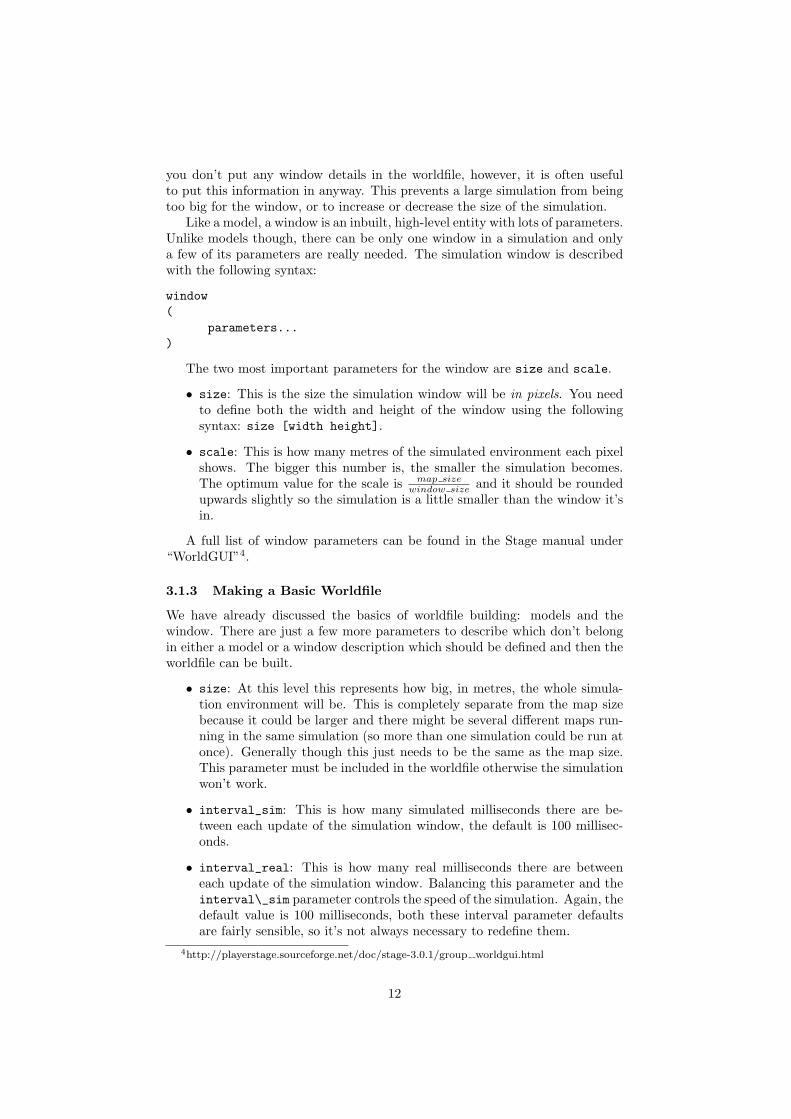
Bigbob is a rubbish-collector so here we should tell it what colour of rubbishto look for. Let’s say that the intended application of Bigbob is in an orangejuice factory and he picks up any stray oranges or juice cartons that fall on thefloor. Oranges are orange, and juice cartons are (let’s say) dark blue so Bigbob’sblobfinder will look for these two colours:
define bigbobs_eyes blobfinder(
# number of colours to look forcolors_count 2
23
# which colours to look forcolors ["orange" "DarkBlue"]
)
Then we define the properties of the camera, again these come from a datasheet:
define bigbobs_eyes blobfinder(
# number of colours to look forcolors_count 2
# which colours to look forcolors ["orange" "DarkBlue"]
# camera parametersimage [160 120] #resolutionrange 5.00fov 3.14159/3 # 60 degrees = pi/3 radians
)
In Stage 2.X.X the following code should be used instead:
# bigbob’s blobfinderdefine bigbobs_eyes ptz(
blobfinder(
# number of colours to look forchannels_count 2
# which colours to look forchannels ["orange" "DarkBlue"]
# camera parametersimage [160 120] #resolutionrange_max 5.00ptz [0 0 60]
))
The last sensor that needs adding to Bigbob is the laser, which will be usedto detect whenever a piece of rubbish has been collected. Following the sameprinciples as for our previous sensor models we can create a description of thislaser:
define bigbobs_laser laser(
range_min 0.0
# distance between teeth in metresrange_max 0.25
24

Figure 13: The position of Bigbob’s laser (in red) and its distance, in metres,relative to its origin (marked with a cross).
fov 3.14159/9 # 20 degrees = pi/9 radians# fov 20 # use this line instead of above if using stage 2.X.X
pose [0.625 0.125 270]size [0.025 0.025]
)
With this laser we’ve set its maximum range to be the distance between teeth,and the field of view is arbitrarily set to 20◦. We have calculated the laser’spose in exactly the same way as the sonars spose, by measuring the distancefrom the laser’s centre to the robot’s centre of rotation, the laser’s yaw is set to270◦ so that it points across Bigbob’s teeth. We also set the size of the laser tobe 2.5cm square so that it doesn’t obstruct the gap between Bigbob’s teeth.
Now that we have a robot body and sensor models all we need to do is putthem together and place them in the world. To add the sensors to the body weneed to go back to the bigbob position model:
define bigbob position(
# actual sizesize [1.25 1]# centre of rotation offsetorigin [0.125 0 0]
# the shape of Bigbobpolygons 3.........
25

# positonal thingsmass 10.0drive "diff"
# sensors attached to bigbobbigbobs_sonars()bigbobs_eyes()bigbobs_laser()
)
The extra line bigbobs_sonars() adds the sonar model called bigbobs_sonars()onto the bigbob model, likewise for bigbobs_eyes() and bigbobs_laser().After this final step we now have a complete model of our robot bigbob, the fullcode for which can be found in appendix A. At this point it’s worthwhile to copythis into a .inc file, so that the model could be used again in other simulationsor worlds.To put our Bigbob model into our empty world (see section 3.1.3) we need toadd the robot to our worldfile empty.world:
include "map.inc"include "bigbob.inc"
# size of the whole simulationsize [15 15]
# configure the GUI windowwindow(
size [ 700.000 700.000 ]scale 0.025
)
# load an environment bitmapmap(
bitmap "bitmaps/cave.png"size [15 15]
)
bigbob(
name "bob1"pose [-5 -6 45]color "red"
)
Here we’ve put all the stuff that describes Bigbob into a .inc file bigbob.inc,and when we include this, all the code from the .inc file is inserted into the
26

.world file. The section here is where we put a version of the bigbob model intoour world:
bigbob(
name "bob1"pose [-5 -6 45]color "green"
)
Bigbob is a model description, by not including any define stuff in the topline there it means that we are making an instantiation of that model, withthe name bob1. Using an object-oriented programming analogy, bigbob is ourclass, and bob1 is our object of class bigbob. The pose [x y yaw] parameterworks in the same was as spose [x y yaw] does. The only differences are thatthe coordinates use the centre of the simulation as a reference point and poselets us specify the initial position and heading of the entire bob1 model, notjust one sensor within that model. Finally we specify what colour bob1 shouldbe, by default this is red. The pose and color parameters could have beenspecified in our bigbob model but by leaving them out it allows us to vary thecolour and position of the robots for each different robot of type bigbob, so wecould declare multiple robots which are the same size, shape and have the samesensors, but are rendered by Player/Stage in different colours and are initialisedat different points in the map.When we run the new empty.world with Player/Stage we see our Bigbob robotis occupying the world, as shown in figure 14. The dark mark on top of therobot is the blobfinder camera.
3.3 Building Other Stuff
We established in section 3.2.2 that Bigbob works in a orange juice factorycollecting oranges and juice cartons. Now we need to build models to representthe oranges and juice cartons so that Bigbob can interact with things.
We’ll start by building a model of an orange:
define orange model(
# parameters...)
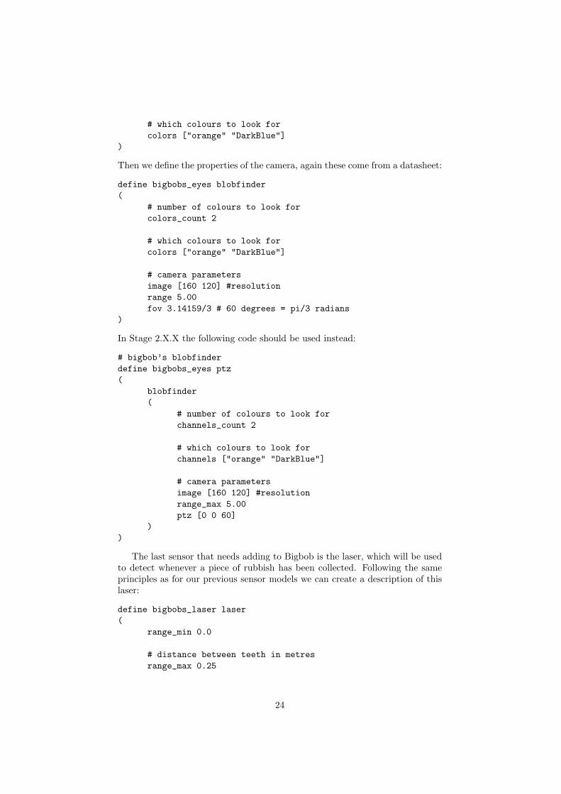
The first thing to define is the shape of the orange. The polygons parameteris one way of doing this, which we can use to build a blocky approximation ofa circle. An alternative to this is to use bitmap which we previously saw beingused to create a map. What the bitmap command actually does is take in apicture, and turn it into a series of polygons which are connected together tomake a model the same shape as the picture. This is illustrated in figure 15.To get rid of the blocks’ outlines add gui_outline 0 to the model description,with the large ghost in figure 15 it’s not so much of a problem, but with smallermodels, like an orange, the black outlines prevent the model’s colour from beingvisible.
27

Figure 14: Our bob1 robot placed in the empty world.
Figure 15: The left image is the original picture, the right image is itsPlayer/Stage interpretation.
28
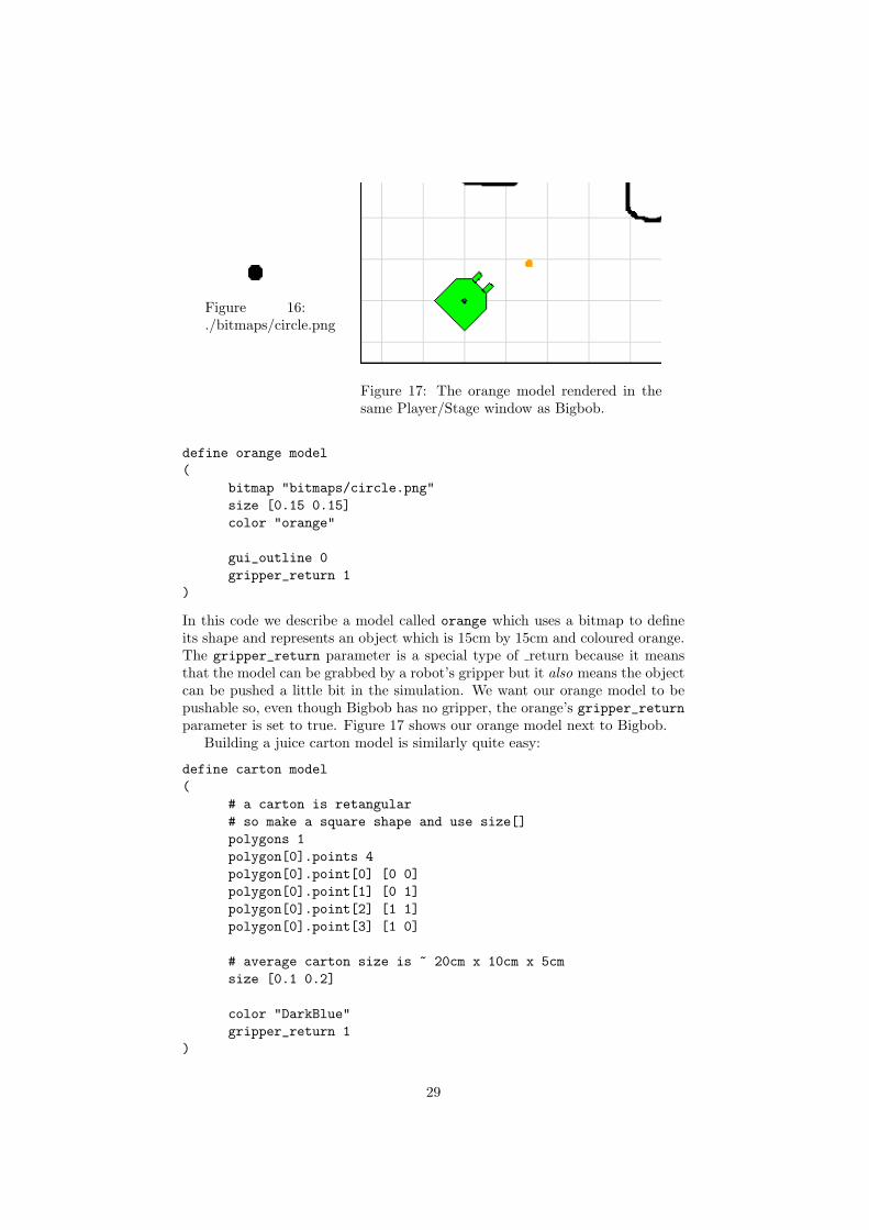
Figure 16:./bitmaps/circle.png
Figure 17: The orange model rendered in thesame Player/Stage window as Bigbob.
define orange model(
bitmap "bitmaps/circle.png"size [0.15 0.15]color "orange"
gui_outline 0gripper_return 1
)
In this code we describe a model called orange which uses a bitmap to defineits shape and represents an object which is 15cm by 15cm and coloured orange.The gripper_return parameter is a special type of return because it meansthat the model can be grabbed by a robot’s gripper but it also means the objectcan be pushed a little bit in the simulation. We want our orange model to bepushable so, even though Bigbob has no gripper, the orange’s gripper_returnparameter is set to true. Figure 17 shows our orange model next to Bigbob.
Building a juice carton model is similarly quite easy:
define carton model(
# a carton is retangular# so make a square shape and use size[]polygons 1polygon[0].points 4polygon[0].point[0] [0 0]polygon[0].point[1] [0 1]polygon[0].point[2] [1 1]polygon[0].point[3] [1 0]
# average carton size is ~ 20cm x 10cm x 5cmsize [0.1 0.2]
color "DarkBlue"gripper_return 1
)
29

We can use the polygons command since juice cartons are boxy, with boxythings it’s slightly easier to describe the shape with polygon than drawing abitmap and using that.
Now that we have described basic orange and carton models it’s time toput some oranges and cartons into the simulation. This is done in the same wayas our example robot was put into the world:
orange(
name "orange1"pose [-2 -5 0]
)
carton(
name "carton1"pose [-3 -5 0]
)
We created models of oranges and cartons, and now we are declaring that therewill be an instance of these models (called orange1 and carton1 respectively) atthe given positions. Unlike with the robot, we declared the color of the modelsin the description so we don’t need to do that here. If we did have differentcolours for each orange or carton then it would mess up the blobfinding onBigbob because the robot is only searching for orange and dark blue. At thispoint it would be useful if we could have more than just one orange or cartonin the world (Bigbob would not be very busy if there wasn’t much to pick up),it turns out that this is also pretty easy:
orange(name "orange1" pose [-1 -5 0])orange(name "orange2" pose [-2 -5 0])orange(name "orange3" pose [-3 -5 0])orange(name "orange4" pose [-4 -5 0])
carton(name "carton1" pose [-2 -4 0])carton(name "carton2" pose [-2 -3 0])carton(name "carton3" pose [-2 -2 0])carton(name "carton4" pose [-2 -1 0])
Up until now we have been describing models with each parameter on anew line, this is just a way of making it more readable for the programmer –especially if there are a lot of parameters. If there are only a few parametersor you want to repeat the code (as we’ve done here) it can all be put onto oneline. Here we declare that there will be four orange models in the simulationwith the names orange1 to orange4, we also need to specify different poses forthe models so they aren’t all on top of each other. Properties that the orangemodels have in common (such as shape, colour or size) should all be in themodel definition.
The full worldfile is included in appendix B, this includes the orange andcarton models as well as the code for putting them in the simulation. Figure 18shows the populated Player/Stage simulation.
30

Figure 18: The Bigbob robot placed in the simulation along with junk for it topick up.
4 Writing a Configuration (.cfg) File
As mentioned earlier, Player is a hardware abstraction layer which connectsyour code to the robot’s hardware. It does this by acting as a Server/Clienttype program where your code and the robot’s sensors are clients to a Playerserver which then passes the data and instructions around to where it all needsto go. This stuff will be properly explained in section 5, it all sounds morecomplicated than it is because Player/Stage takes care of all the difficult stuff.The configuration file is needed in order to tell the Player server which driversto use and which interfaces the drivers will be using.
For each model in the simulation or device on the robot that you wantto interact with, you will need to specify a driver. This is far easier thanwriting worldfile information, and follows the same general syntax. The driverspecification is in the form:
driver(
name "driver_name"provides [device_address]# other parameters...
)
The name and provides parameters are mandatory information, without themPlayer won’t know which driver to use (given by name) and what kind of in-formation is coming from the driver (provides). The name parameter is not
31
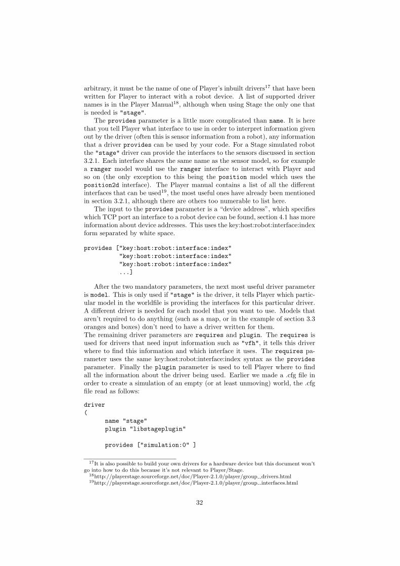
arbitrary, it must be the name of one of Player’s inbuilt drivers17 that have beenwritten for Player to interact with a robot device. A list of supported drivernames is in the Player Manual18, although when using Stage the only one thatis needed is "stage".
The provides parameter is a little more complicated than name. It is herethat you tell Player what interface to use in order to interpret information givenout by the driver (often this is sensor information from a robot), any informationthat a driver provides can be used by your code. For a Stage simulated robotthe "stage" driver can provide the interfaces to the sensors discussed in section3.2.1. Each interface shares the same name as the sensor model, so for examplea ranger model would use the ranger interface to interact with Player andso on (the only exception to this being the position model which uses theposition2d interface). The Player manual contains a list of all the differentinterfaces that can be used19, the most useful ones have already been mentionedin section 3.2.1, although there are others too numerable to list here.
The input to the provides parameter is a “device address”, which specifieswhich TCP port an interface to a robot device can be found, section 4.1 has moreinformation about device addresses. This uses the key:host:robot:interface:indexform separated by white space.
provides ["key:host:robot:interface:index""key:host:robot:interface:index""key:host:robot:interface:index"...]
After the two mandatory parameters, the next most useful driver parameteris model. This is only used if "stage" is the driver, it tells Player which partic-ular model in the worldfile is providing the interfaces for this particular driver.A different driver is needed for each model that you want to use. Models thataren’t required to do anything (such as a map, or in the example of section 3.3oranges and boxes) don’t need to have a driver written for them.The remaining driver parameters are requires and plugin. The requires isused for drivers that need input information such as "vfh", it tells this driverwhere to find this information and which interface it uses. The requires pa-rameter uses the same key:host:robot:interface:index syntax as the providesparameter. Finally the plugin parameter is used to tell Player where to findall the information about the driver being used. Earlier we made a .cfg file inorder to create a simulation of an empty (or at least unmoving) world, the .cfgfile read as follows:
driver(
name "stage"plugin "libstageplugin"
provides ["simulation:0" ]
17It is also possible to build your own drivers for a hardware device but this document won’tgo into how to do this because it’s not relevant to Player/Stage.
18http://playerstage.sourceforge.net/doc/Player-2.1.0/player/group drivers.html19http://playerstage.sourceforge.net/doc/Player-2.1.0/player/group interfaces.html
32

# load the named file into the simulatorworldfile "empty.world"
)
This has to be done at the beginning of the configuration file because it tellsPlayer that there is a driver called "stage" that we’re going to use and the codefor dealing with this driver can be found in the libstageplugin plugin. Thisneeds to be specified for Stage because Stage is an add-on for Player, for driversthat are built into Player by default the plugin doesn’t need to be specified.
4.1 Device Addresses - key:host:robot:interface:index
A device address is used to tell Player where the driver you are making willpresent (or receive) information and which interface to use in order to read thisinformation. This is a string in the form key:host:robot:interface:indexwhere each field is separated by a colon.
• key: The Player manual states that: “The purpose of the key field is toallow a driver that supports multiple interfaces of the same type to mapthose interfaces onto different devices”[1]. This is a driver level thing andhas a lot to do with the name of the driver that you are using, generally for"stage" the key doesn’t need to be used. If you’re using Player withoutStage then there is a useful section about device address keys in the Playermanual20.
• host: This is the address of the host computer where the device is located.With a robot it could be the IP address of the robot. The default host is“localhost” which means the computer on which Player is running.
• robot: this is the TCP port through which Player should expect to receivedata from the interface usually a single robot and all its necessary inter-faces are assigned to one port. The default port used is 6665, if there weretwo robots in the simulation the ports could be 6665 and 6666 althoughthere’s no rule saying which number ports you can or can’t use.
• interface: The interface to use in order to interact with the data. Thereis no default value for this option because it is a mandatory field.
• index: If a robot has multiple devices of the same type, for instance it has2 cameras to give the robot depth perception, each device uses the sameinterface but gives slightly different information. The index field allowsyou to give a slightly different address to each device. So two camerascould be camera:0 and camera:1. This is very different from the keyfield because having a “driver that supports multiple interfaces of thesame type” is NOT the same as having multiple devices that use the sameinterface. Again there is no default index, as this is a mandatory field inthe device address, but you should use 0 as the index if there is only oneof that kind of device.
If you want to use any of the default values it can just be left out of the deviceaddress. So we could use the default host and robot port and specify (for exam-ple) a laser interface just by doing "laser:0". However, if you want to specify
20http://playerstage.sourceforge.net/doc/Player-2.1.0/player/group tutorial config.html#device key
33

fields at the beginning of the device address but not in the middle then the sepa-rating colons should remain. For example if we had a host at "127.0.0.1" witha laser interface then we would specify the address as "127.0.0.1::laser:0",the robot field is empty but the colons around it are still there. You may noticethat the key field here was left off as before.
4.2 Putting the Configuration File Together
We have examined the commands necessary to build a driver for a model in theworldfile, now it is just a case of putting them all together. To demonstrate thisprocess we will build a configuration file for the worldfile developed in section3. In this world we want our code to be able to interact with the robot, so inour configuration file we need to specify a driver for this robot.
driver(
# parameters...)
The inbuilt driver that Player/Stage uses for simulations is called "stage"so the driver name is "stage".
driver(
name "stage")
The Bigbob robot uses position, laser, blobfinder and ranger sensors.These correspond to the position2d, laser, blobfinder and interfaces re-spectively. The ranger sensor is a special case because the ranger interface hasnot currently been implemented (for versions Stage 3.0.1 or earlier). To workaround this you’ll need to use the sonar interfaces instead (there is apparentlyan IR interface which could be used instead of ranger, but it doesn’t seem towork on either Stage 2 or Stage 3).
We want our code to be able to read from these sensors, so we need todeclare interfaces for them and tell Player where to find each device’s data, forthis we use the configuration file’s provides parameter. This requires that weconstruct device addresses for each sensor; to remind ourselves, this is in thekey:host:robot:interface:index format. We aren’t using any fancy drivers, so wedon’t need to specify a key. We are running our robot in a simulation on thesame computer as our Player sever, so the host name is localhost which isthe default, so we also don’t need to specify a host. The robot is a TCP portto receive robot information over, picking which port to use is pretty arbitrarybut what usually happens is that the first robot uses the default port 6665and subsequent robots use 6666, 6667, 6668 etc. There is only one robot in oursimulation so we will use port 6665 for all our sensor information from this robot.We only have one sensor of each type, so our devices don’t need separate indices.What would happen if we did have several sensors of the same type (like saytwo cameras) is that we put the first device at index 0 and subsequent devicesusing the same interface have index 1, then 2, then 3 and so on.21 Finally we
21There are lots of ranger sensors in our model but when we created the robot’s sensors insection 3.2.2 we put them all into the same ranger model. So as far as the configuration file
34

use interfaces appropriate to the sensors the robot has, so in our example theseare the position, laser, blobfinder interfaces and for our ranger devices wewill use sonar.
Putting all this together under the provides parameter gives us:
driver(name "stage"provides ["6665:position2d:0"
"6665:sonar:0""6665:blobfinder:0""6665:laser:0" ]
)
The device addresses can be on the same line as each other or separate lines,just so long as they’re separated by some form of white space.
The last thing to do on our driver is the model "model_name" parameterwhich needs to be specified because we are using Player/Stage. This tells thesimulation software that anything you do with this driver will affect the model"model_name" in the simulation. In the simulation we built we named our robotmodel “bob1”, so our final driver for the robot will be:
driver(
name "stage"provides ["6665:position2d:0"
"6665:sonar:0""6665:blobfinder:0""6665:laser:0"]
model "bob1")
If our simulation had multiple Bigbob robots in, the configuration file driverswould be very similar to one another. If we created a second robot in ourworldfile and called it “bob2” then the driver would be:
driver(
name "stage"provides ["6666:position2d:0"
"6666:sonar:0""6666:blobfinder:0""6666:laser:0"]
model "bob2")
Notice that the port number and model name are the only differences becausethe robots have all the same sensors.
is concerned there is only one raging device using either the sonar or IR interface, becauseall the separate ranger devices are lumped together into this one model. We don’t need todeclare each ranger on an index of its own.
35

A driver of this kind can be built for any model that is in the worldfile,not just the robots. For instance a map driver can be made which uses themap interface and will allow you to get size, origin and occupancy data aboutthe map. The only requirement is that if you want to do something to themodel with your code then you need to build a driver for it in the configurationfile. Finally when we put the bit which declares the stage driver (this part iscompulsory for any simulation configuration file) together with our drivers forthe robot we end up with our final configuration file:
driver(
name "stage"plugin "libstageplugin"
provides ["simulation:0" ]
# load the named file into the simulatorworldfile "worldfile_name.world"
)
driver(
name "stage"provides ["6665:position2d:0"
"6665:sonar:0""6665:blobfinder:0""6665:laser:0"]
model "bob1")
5 Getting Your Simulation To Run Your Code
To learn how to write code for Player or Player/Stage it helps to understand thebasic structure of how Player works. Player uses a Server/Client structure inorder to pass data and instructions between your code and the robot’s hardware.Player is a server, and a hardware device22 on the robot is subscribed as a clientto the server via a thing called a proxy. The .cfg file associated with your robot(or your simulation) takes care of telling the Player server which devices areattached to it, so when we run the command player some_cfg.cfg this startsup the Player server and connects all the necessary hardware devices to theserver. Figure 19 shows a basic block diagram of the structure of Player whenimplemented on a robot. In Player/Stage the same command will start thePlayer server and load up the worldfile in a simulation window, this runs onyour computer and allows your code to interact with the simulation rather thanhardware. Figure 20 shows a basic block diagram of the Player/Stage structure.Your code must also subscribe to the Player server so that it can access theseproxies and hence control the robot. Player has functions and classes which will
22remember, a device is a piece of hardware that uses a driver which conforms to an interface.See section 2.2
36

Figure 19: The server/client control structure of Player when used on a robot.There may be several proxies connected to the server at any time.
do all this for you, but you still need to actually call these functions with yourcode and know how to use them.
Player is compatable with C, C++ or Python code, however in this manualwe will only really be using C++ because it is the simplest to understand. Theprocess of writing Player code is mostly the same for each different languagethough. The Player and Player proxy functions have different names for eachlanguage, but work in more or less the same way, so even if you don’t plan onusing C++ or Stage this section will still contain helpful information.
Before beginning a project it is highly recommended that for any programsother than basic examples you should always wrap your Player commandsaround your own functions and classes so that all your code’s interactions withPlayer are kept together the same file. This isn’t a requirement of Player, it’sjust good practice. For example, if you upgrade Player or if for some reason yourrobot breaks and a certain function no longer works you only have to changepart of a file instead of searching through all your code for places where Playerfunctions have been used.
Finally, in order to compile your program you use the following commands(in Linux):g++ -o example0 `pkg-config --cflags playerc++` example0.cc `pkg-config--libs playerc++`
That will compile a program to a file called example0 from the C++ codefile example0.cc. If you are coding in C instead then use the following com-mand:gcc -o example0 `pkg-config --cflags playerc` example0.c `pkg-config--libs playerc`
5.1 Connecting to the Server and Proxies With Your Code
The first thing to do within your code is to include the Player header file.Assuming Player/Stage is installed correctly on your machine then this can be
37

Figure 20: The server/client control structure of Player/Stage when used as asimulator. There may be several proxies connected to the server at any time.
done with the line #include <libplayerc++/playerc++.h> (if you’re using Cthen type #include <libplayerc/playerc.h> instead).
Next we need to establish a Player Client, which will interact with the Playerserver for you. To do this we use the line:
PlayerClient client_name(hostname, port);
What this line does is declare a new object which is a PlayerClient calledclient_name which connects to the Player server at the given address. Thehostname and port is like that discussed in section 4.1. If your code is run-ning on the same computer (or robot) as the Player server you wish to connectto then the hostname is “localhost” otherwise it will be the IP address of thecomputer or robot. The port is an optional parameter usually only needed forsimulations, it will be the same as the port you gave in the .cfg file. This isonly useful if your simulation has more than one robot in and you need yourcode to connect to both robots. So if you gave your first robot port 6665 andthe second one 6666 (like in the example of section 4.2) then you would needtwo PlayerClients, one connected to each robot, and you would do this with thefollowing code:
PlayerClient robot1("localhost", 6665);PlayerClient robot2("localhost", 6666);
If you are only using one robot and in your .cfg file you said that it wouldoperate on port 6665 then the port parameter to the PlayerClient class is notneeded.Once we have established a PlayerClient we should connect our code to the de-vice proxies so that we can exchange information with them. Which proxies youcan connect your code to is dependent on what you have put in your configura-tion file. For instance if your configuration file says your robot is connected to alaser but not a camera you can connect to the laser device but not the camera,even if the robot (or robot simulation) has a camera on it.
38

Proxies take the name of the interface which the drivers use to talk to Player.Let’s take part of the Bigbob example configuration file from section 4.2:
driver(name "stage"provides ["6665:position2d:0"
"6665:sonar:0""6665:blobfinder:0""6665:laser:0" ]
)
Here we’ve told the Player server that our “robot” has devices which use theposition2d, sonar, blobfinder and laser interfaces. In our code then, we shouldconnect to the position2d, sonar, blobfinder and laser proxies like so:
Position2dProxy positionProxy_name(&client_name,index);SonarProxy sonarProxy_name(&client_name,index);BlobfinderProxy blobProxy_name(&client_name,index);LaserProxy laserProxy_name(&client_name,index);
A full list of which proxies Player supports can be found in the Player manual23,they all follow the convention of being named after the interface they use. Inthe above case xProxy_name is the name you want to give to the proxy object,client_name is the name you gave the PlayerClient object earlier and index isthe index that the device was given in your configuration file (probably 0).
5.1.1 Setting Up Connections: an Example.
For an example of how to connect to the Player sever and device proxies we willuse the example configuration file developed in section 4.2. For convenience thisis reproduced below:
driver(
name "stage"plugin "libstageplugin"
provides ["simulation:0" ]
# load the named file into the simulatorworldfile "worldfile_name.world"
)
driver(
name "stage"provides ["6665:position2d:0"
"6665:sonar:0""6665:blobfinder:0"
23http://playerstage.sourceforge.net/doc/Player-2.1.0/player/classPlayerCc 1 1ClientProxy.html
39

"6665:laser:0"]model "bob1"
)
To set up a PlayerClient and then connect to proxies on that server we can useprinciples discussed in this section to develop the following code:
#include <stdio.h>#include <libplayerc++/playerc++.h>
int main(int argc, char *argv[]){
/*need to do this line in c++ only*/using namespace PlayerCc;
PlayerClient robot("localhost");
Position2dProxy p2dProxy(&robot,0);SonarProxy sonarProxy(&robot,0);BlobfinderProxy blobProxy(&robot,0);LaserProxy laserProxy(&robot,0);
//some control codereturn 0;
}
5.2 Interacting with Proxies
As you may expect, each proxy is specialised towards controlling the device itconnects to. This means that each proxy will have different commands depend-ing on what it controls. In Player version 2.1.0 there are 38 different proxieswhich you can choose to use, many of which are not applicable to Player/Stage.This manual will not attempt to explain them all, a full list of avaliable proxiesand their functions is in the Player manual24, although the returns, parametersand purpose of the proxy function is not always explained.The following few proxies are probably the most useful to anyone using Playeror Player/Stage.
5.2.1 Position2dProxy
The Position2dProxy is the number one most useful proxy there is. It controlsthe robot’s motors and keeps track of the robot’s odometry (where the robotthinks it is based on how far its wheels have moved).
Get/SetSpeed The SetSpeed command is used to tell the robot’s motorshow fast to turn. There are two different SetSpeed commands that can becalled, one is for robots that can move in any direction and the other is forrobots with differential or car-like drives.
• SetSpeed(double XSpeed, double YSpeed, double YawSpeed)
24http://playerstage.sourceforge.net/doc/Player-2.1.0/player/classPlayerCc 1 1ClientProxy.html
40

Figure 21: A robot on a cartesian grid. This shows what directions the X andY speeds will cause the robot to move in. A positive yaw speed will turn therobot in the direction of the + arrow, a negative yaw speed is the direction ofthe - arrow.
• SetSpeed(double XSpeed, double YawSpeed)
• SetCarlike(double XSpeed, double DriveAngle)
Figure 21 shows which direction the x, y and yaw speeds are in relation to therobot. The x speed is the rate at which the robot moves forward and the yspeed is the robot’s speed sideways, both are to be given in metres per second.The y speed will only be useful if the robot you want to simulate or control isa ball, since robots with wheels cannot move sideways. The yaw speed controlshow fast the robot is turning and is given in radians per second, Player has aninbuilt global function called dtor() which converts a number in degrees intoa number in radians which could be useful when setting the yaw speed. If youwant to simulate or control a robot with a differential drive system then you’llneed to convert left and right wheel speeds into a forward speed and a turningspeed before sending it to the proxy. For car-like drives there is the SetCarlikewhich, again is the forward speed in m/s and the drive angle in radians.
The GetSpeed commands are essentially the reverse of the SetSpeed com-mand. Instead of setting a speed they return the current speed relative to therobot (so x is the forward speed, yaw is the turning speed and so on).
• GetXSpeed: forward speed (metres/sec).
• GetYSpeed: sideways (perpendicular) speed (metres/sec).
• GetYawSpeed: turning speed (radians/sec).
Get Pos This function interacts with the robot’s odometry. It allows you tomonitor where the robot thinks it is. Coordinate values are given relative to itsstarting point, and yaws are relative to its starting yaw.
• GetXPos(): gives current x coordinate relative to its x starting position.
41

• GetYPos(): gives current y coordinate relative to its y starting position.
• GetYaw(): gives current yaw relative to its starting yaw.
In section 3.2.1, we specified whether it would record odometry by measur-ing how much its wheels have turned, or whether the robot would have perfectknowledge of its current coordinates (by default the robot does not record odom-etry at all). If you set the robot to record odometry using its wheels then thepositions returned by these get commands will become increasingly inaccurateas the simulation goes on. If you want to log your robots position as it movesaround, these functions along with the perfect odometry25 setting can be used.
SetMotorEnable() This function takes a boolean input, telling Player whetherto enable the motors or not. If the motors are disabled then the robot will notmove no matter what commands are given to it, if the motors are enabled thenthe motors will always work, this is not so desirable if the robot is on a deskor something and is likely to get damaged. Hence the motors being enabled isoptional. If you are using Player/Stage, then the motors will always be enabledand this command doesn’t need to be run. However, if your code is ever likelyto be moved onto a real robot and the motors are not explicitly enabled in yourcode, then you may end up spending a long time trying to work out why yourrobot is not working.
5.2.2 SonarProxy
The sonar proxy can be used to receive the distance from the sonar to an obstaclein metres. To do this you use the command:
• sonarProxy_name[sonar_number]
Where sonarProxy_name is the SonarProxy object and sonar_number is thenumber of the ranger. In Player/Stage the sonar numbers come from the orderin which you described the ranger devices in the worldfile. In section 3.2.2 wedescribed the ranger sensors for the Bigbob robot like so:
define bigbobs_sonars ranger(
# number of sonarsscount 4
# define the pose of each transducer [xpos ypos heading]spose[0] [ 0.75 0.1875 0 ] #fr left toothspose[1] [ 0.75 -0.1875 0 ] #fr right toothspose[2] [ 0.25 0.5 30] # left cornerspose[3] [ 0.25 -0.5 -30] # right corner
)
In this example sonarProxy_name[0] gives us the distance from the left toothranger to an obstacle, sonarProxy_name[1] gives the distance from the frontright tooth to an obstacle, and so on. If no obstacle is detected then the functionwill return whatever the ranger’s maximum range is.
25See section 3.2.1 for how to give the robot perfect odometry.
42

Figure 22: How laser angles are referenced. In this diagram the laser is pointingto the right along the dotted line, the angle θ is the angle of a laser scan point,in this example θ is negative.
5.2.3 LaserProxy
A laser is a special case of ranger device, it makes regularly spaced range mea-surements turning from a minimum angle to a maximum angle. Each measure-ment, or scan point, is treated as being done with a separate ranger. Whereangles are given they are given with reference to the laser’s centre front (seefigure 22).
• GetCount: The number of laser scan points that the laser measures.
• laserProxy_name[laser_number] The range returned by the laser_numberth
scan point. Scan points are numbered from the minimum angle at index0, to the maximum angle at index GetCount().
• GetBearing[laser_number]: This gets the angle of the laser scan point.
• GetRange[laser_number]: returns the range measured by the scan pointlaser_number. This is the same as doing laserProxy_name[laser_number].
• MinLeft: Gives the minimum range returned by a scan point on the lefthand side of the laser.
• MinRight: Gives the minimum range returned by a scan point on the righthand side of the laser.
5.2.4 RangerProxy
The RangerProxy is a proxy for more general ranging, it supports the sonar,laser and IR proxies. It has the same function as the SonarProxy in that you canuse the code rangerProxy_name[ranger_number] to return the distance fromranger ranger_number to an obstacle. It also has many of the same functions
43

Figure 23: A laser scanner. The minimum angle is the angle of the rightmostlaser scan, the maximum angle is the leftmost laser scan. θ is the scan resolutionof the laser, it is the angle between each laser scan, given in 0.01 degrees.
as the LaserProxy, such as a minimum angle and a maximum angle and ascanning resolution, mostly these are for retrieving data about how the rangersare arranged or what size the ranging devices are.
5.2.5 BlobfinderProxy
The blobfinder module analyses a camera image for areas of a desired colourand returns an array of the structure playerc_blobfinder_blob_t, this is thestructure used to store blob data. First we will cover how to get this data fromthe blobfinder proxy, then we will discuss the data stored in the structure.
• GetCount: Returns the number of blobs seen.
• blobProxy_name[blob_number]: This returns the blob structure data forthe blob with the index blob_number. Blobs are sorted by index in theorder that they appear in the image from left to right. This can also beachieved with the BlobfinderProxy function GetBlob(blob_number).
Once we receive the blob structure from the proxy we can extract data weneed. The playerc_blobfinder_blob_t structure contains the following fields:
• color: The colour of the blob it detected. This is given as a hexadecimalvalue.
• area: The area of the blob’s bounding box.
• x: The horizontal coordinate of the geometric centre of the blob’s boundingbox (see figure 24).
• y: The vertical coordinate of the geometric centre of the blob’s boundingbox (see figure 24).
• left: The horizontal coordinate of the left hand side of the blob’s bound-ing box (see figure 24).
44

Figure 24: What the fields in playerc blobfinder blob t mean. The blob onthe left has a geometric centre at (x, y), the blob on the right has a boundingbox with the top left corner at (left, top) pixels, and a lower right coordinateat (right, bottom) pixels. Coordinates are given with reference to the top leftcorner of the image.
• right: The horizontal coordinate of the right hand side of the blob’sbounding box (see figure 24).
• top: The vertical coordinate of the top side of the blob’s bounding box(see figure 24).
• bottom: The vertical coordinate of the bottom side of the blob’s boundingbox (see figure 24).
5.2.6 GripperProxy
The GripperProxy allows you to control the gripper, once the gripper is holdingan item, the simulated robot will carry it around wherever it goes. Without agripper you can only jostle an item in the simulation and you would have tomanually tell the simulation what to do with an item. The GripperProxy canalso tell you if an item is between the gripper teeth because the gripper modelhas inbuilt beams which can detect if they are broken.
• GetBeams: This command will tell you if there is an item inside the grip-per. If it is a value above 0 then there is an item to grab.
• GetState: This will tell you whether the gripper is opened or closed. Ifthe command returns a 1 then the gripper is open, if it returns 2 then thegripper is closed.
• Open: Tells the gripper to open. This will cause any items that were beingcarried to be dropped.
45

• Close: Tells the gripper to close. This will cause it to pick up anythingbetween its teeth.
5.2.7 SimulationProxy
The simulation proxy allows your code to interact with and change aspects ofthe simulation, such as an item’s pose or its colour.
Get/Set Property To change a property of an item in the simulation we usethe following function:SetProperty(char *item_name, char *property, void *value, size_t value_len)
• item_name: this is the name that you gave to the object in the worldfile, itcould be any model that you have described in the worldfile. For example,in section 3.2.2 in the worldfile we declared a Bigbob type robot which wecalled “bob1” so the item_name for that object is “bob1”. Similarly insection 3.3 we built some models of oranges and called the “orange1” to“orange4” so the item name for one of these would be “orange1”. Anythingthat is a model in your worldfile can be altered by this function, you justneed to have named it, no drivers need to be declared in the configurationfile for this to work either. We didn’t write drivers for the oranges but wecould still alter their properties this way.
• property: There are only certain properties about a model that you canchange. You specify which one you want with a string. Since the propertiesyou can change are fixed then these strings are predefined (see stage.hh):
– "_mp_color": The colour of the item.
– "_mp_watts": The number of watts the item needs.
– "_mp_mass": The mass of the item.
– "_mp_fiducial_return": sets whether the item is detectable to thefiducial finder on a robot.
– "_mp_laser_return": sets whether the item is detectable to the laseron a robot.
– "_mp_obstacle_return": sets whether the robot can collide withthe item.
– "_mp_ranger_return": sets whether the item is detectable to therangers on a robot.
– "_mp_gripper_return": sets whether the item can be gripped by agripper or jostled by the robot colliding with it.
• value: The value you want to assign to the property. For the returnparameters this can simply be a 0 or a 1, for the watts and mass it can bea numerical value. For the colour of the item this is a uint32_t 8 digitlong hexadecimal number. The first 2 digits are the alpha value of thecolour, the second two are its red value, the next two are its green valueand the final two are the blue colour value. So red, for instance, would beuint32 t red = 0xffff0000, green would be 0xff00ff00 and blue is 0xff0000ff.A nice shade of yellow might be 0xffffcc11.
46

• value_len: is the size of the value you gave in bytes. This can easily befound with the C or C++ sizeof() operator.
Similarly the following function can be used to get property information:GetProperty(char *item_name, char *property, void *value, size_t value_len)Instead of setting the given property of the item, this will write it to the memoryblock pointed to by *value.
Get/Set Pose The item’s pose is a special case of the Get/SetProperty func-tion, because it is likely that someone would want to move an item in the worldthey created a special function to do it.SetPose2d(char *item_name, double x, double y, double yaw)In this case item_name is as with Get/SetProperty, but we can directly specifyits new coordinates and yaw (coordinates and yaws are given with reference tothe map’s origin).GetPose2d(char *item_name, double &x, double &y, double &yaw)This is like SetPose2d only this time it writes the coordinates and yaw to thegiven addresses in memory.
5.2.8 General Useful Commands
Read() To make the proxies update with new sensor data we need to tellthe player server to update, we can do this using the PlayerClient object whichwe used to connect to the server. All we have to do is run the commandplayerClient_name.Read() every time the data needs updating (where player-Client name is the name you gave the PlayerClient object). Until this commandis run, the proxies and any sensor information from them will be empty. Thedevices on a typical robot are asynchronous and the devices in a Player/Stagesimulation are also asynchronous, so running the Read() command won’t alwaysupdate everything at the same time, so it may take several calls before somelarge data structures (such as a camera image) gets updated.
GetGeom() Most of the proxies have a function called GetGeom or GetGeometryor RequestGeometry, or words to that effect. What these functions do is tell theproxy retrieve information about the device, usually its size and pose (relativeto the robot). The proxies don’t know this by default since this informationis specific to the robot or the Player/Stage robot model. If your code needsto know this kind of information about a device then the proxy must run thiscommand first.
5.3 Using Proxies: A Case Study
To demonstrate how to write code to control a Player device or Player/Stagesimulation we will use the example robot “Bigbob” developed in sections 3.2and 4 which collects oranges and juice cartons from a factory floor. In previoussections we have developed the Stage model for this robot and its environmentand the configuration file to control it. Now we can begin to put everythingtogether to create a working simulation of this robot.
47
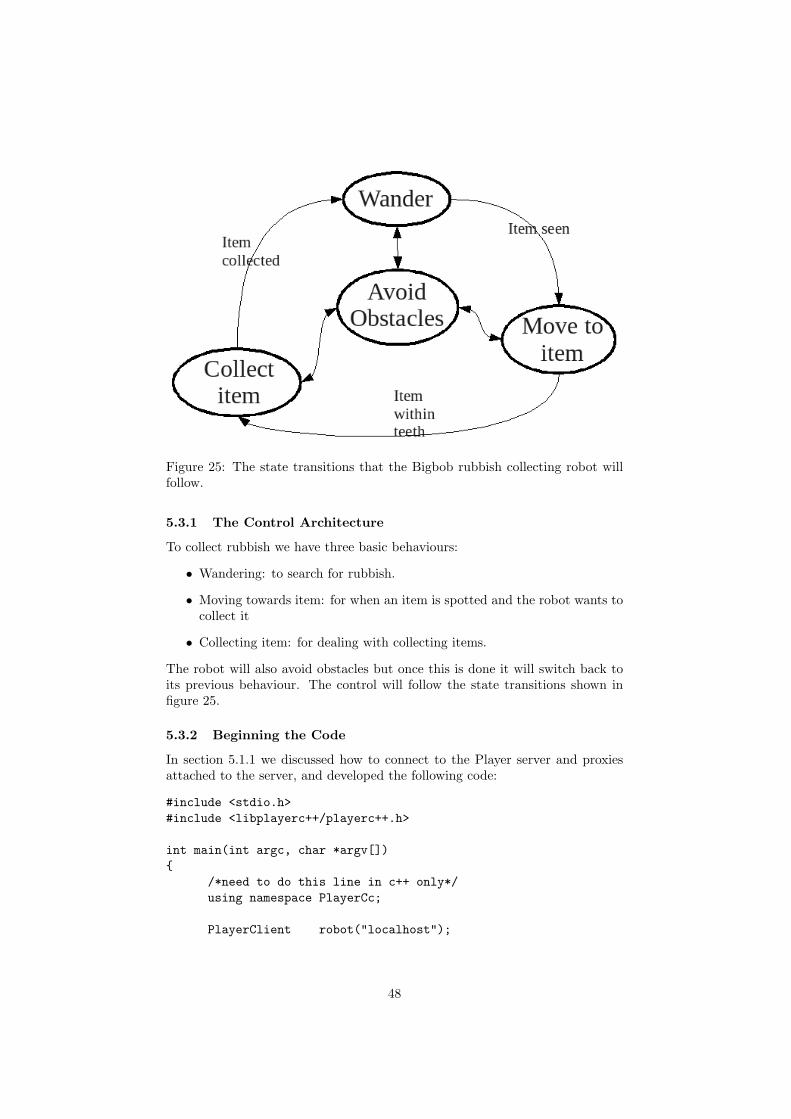
Figure 25: The state transitions that the Bigbob rubbish collecting robot willfollow.
5.3.1 The Control Architecture
To collect rubbish we have three basic behaviours:
• Wandering: to search for rubbish.
• Moving towards item: for when an item is spotted and the robot wants tocollect it
• Collecting item: for dealing with collecting items.
The robot will also avoid obstacles but once this is done it will switch back toits previous behaviour. The control will follow the state transitions shown infigure 25.
5.3.2 Beginning the Code
In section 5.1.1 we discussed how to connect to the Player server and proxiesattached to the server, and developed the following code:
#include <stdio.h>#include <libplayerc++/playerc++.h>
int main(int argc, char *argv[]){
/*need to do this line in c++ only*/using namespace PlayerCc;
PlayerClient robot("localhost");
48

Position2dProxy p2dProxy(&robot,0);SonarProxy sonarProxy(&robot,0);BlobfinderProxy blobProxy(&robot,0);LaserProxy laserProxy(&robot,0);
//some control codereturn 0;
}
Using our knowledge of the proxies discussed in section 5.2 we can build con-trolling code on top of this basic code. Firstly, it is good practice to enable themotors and request the geometry for all the proxies. This means that the robotwill move and that if we need to know about the sensing devices the proxies willhave that information available.
//enable motorsp2dProxy.SetMotorEnable(1);
//request geometriesp2dProxy.RequestGeom();sonarProxy.RequestGeom();laserProxy.RequestGeom();//blobfinder doesn’t have geometry
Once things are initialised we can enter the main control loop. At this point weshould tell the robot to read in data from its devices to the proxies.
while(true){
robot.Read();
//control code}
5.3.3 Wander
first we will initialise a couple of variables which will be the forward speed andthe turning speed of the robot, we’ll put this with the proxy initialisations.
Position2dProxy p2dProxy(&robot,0);SonarProxy sonarProxy(&robot,0);BlobfinderProxy blobProxy(&robot,0);LaserProxy laserProxy(&robot,0);
double forwardSpeed, turnSpeed;
Let’s say that Bigbob’s maximum speed is 1 metre/second and it can turn90◦ a second. We will write a small subfunction to randomly assign forward andturning speeds between 0 and the maximum speeds.
void Wander(double *forwardSpeed, double *turnSpeed){
int maxSpeed = 1;
49

int maxTurn = 90;double fspeed, tspeed;
//fspeed is between 0 and 10fspeed = rand()%11;//(fspeed/10) is between 0 and 1fspeed = (fspeed/10)*maxSpeed;
tspeed = rand()%(2*maxTurn);tspeed = tspeed-maxTurn;//tspeed is between -maxTurn and +maxTurn
*forwardSpeed = fspeed;*turnSpeed = tspeed;
}
In the control loop we include a call to this function and then set the resultingspeeds to the motors.
while(true){
// read from the proxiesrobot.Read();
//wanderWander(&forwardSpeed, &turnSpeed);
//set motorsp2dProxy.SetSpeed(forwardSpeed, dtor(turnSpeed));
}
At present the motors are being updated every time this control loop ex-ecutes, and this leads to some erratic behaviour from the robot. Using thesleep()26 command we will tell the control loop to wait one second betweeneach execution. At this point we should also seed the random number generatorwith the current time so that the wander behaviour isn’t exactly the same eachtime. For the sleep command we will need to include unistd.h and to seed therandom number generator with the current system time we will need to includetime.h.
#include <stdio.h>#include <unistd.h>#include <time.h>#include <libplayerc++/playerc++.h>
void Wander(double *forwardSpeed, double *turnSpeed){
//wander code...}
26sleep() is a standard C function and is included in the unistd.h header.
50

int main(int argc, char *argv[]){
/*need to do this line in c++ only*/using namespace PlayerCc;
//connect to proxiesdouble forwardSpeed, turnSpeed;
srand(time(NULL));
//enable motors//request geometries
while(true){
// read from the proxiesrobot.Read();
//wanderWander(&forwardSpeed, &turnSpeed);
//set motorsp2dProxy.SetSpeed(forwardSpeed, dtor(turnSpeed));sleep(1);
}}
5.3.4 Obstacle Avoidance
Now we need to write a subfunction that checks the sonars for any obstaclesand amends the motor speeds accordingly.
void AvoidObstacles(double *forwardSpeed, double *turnSpeed, \SonarProxy &sp)
{//will avoid obstacles closer than 40cmdouble avoidDistance = 0.4;//will turn away at 60 degrees/secint avoidTurnSpeed = 60;
//left corner is sonar no. 2//right corner is sonar no. 3if(sp[2] < avoidDistance){
*forwardSpeed = 0;//turn right*turnSpeed = (-1)*avoidTurnSpeed;return;
}else if(sp[3] < avoidDistance)
51

{*forwardSpeed = 0;//turn left*turnSpeed = avoidTurnSpeed;return;
}else if( (sp[0] < avoidDistance) && \
(sp[1] < avoidDistance)){
//back off a little bit*forwardSpeed = -0.2;*turnSpeed = avoidTurnSpeed;return;
}
return; //do nothing}
This is a very basic obstacle avoidance subfunction will update the motor speedsonly if there is an obstacle to avoid. If we call this function just before sendingdata to the motors then it will overwrite any other behaviours so that theobstacle will be avoided. Once the obstacle is no longer in the way then therobot will continue as it was, this will allow us to transition from any behaviourinto obstacle avoidance and then back again, as per the requirement of ourcontrol structure. All we need to do now is call this function in our controlloop:
while(true){
// read from the proxiesrobot.Read();
//wanderWander(&forwardSpeed, &turnSpeed);
//avoid obstaclesAvoidObstacles(&forwardSpeed, &turnSpeed, sonarProxy);
//set motorsp2dProxy.SetSpeed(forwardSpeed, dtor(turnSpeed));sleep(1);
}
5.3.5 Move To Item
For this state we want the robot to move towards a blob that it has spotted.There may be several blobs in its view at once, so we’ll tell the robot to moveto the largest one because it’s probably the closest to the robot. The followingsubfunction finds the largest blob and turns the robot so that the blob’s centreis near the centre of the image. The robot will then move towards the blob.
52

void MoveToItem(double *forwardSpeed, double *turnSpeed, \BlobfinderProxy &bfp)
{int i, centre;int noBlobs = bfp.GetCount();playerc_blobfinder_blob_t blob;int turningSpeed = 10;
/*number of pixels away from the image centre a blobcan be to be in front of the robot*/int margin = 10;
int biggestBlobArea = 0;int biggestBlob = 0;
//find the largest blobfor(i=0; i<noBlobs; i++){
//get blob from proxyplayerc_blobfinder_blob_t currBlob = bfp[i];
if(currBlob.area > biggestBlobArea){
biggestBlob = i;biggestBlobArea = currBlob.area;
}}blob = bfp[biggestBlob];
// find centre of imagecentre = bfp.GetWidth()/2;
//adjust turn to centre the blob in image/*if the blob’s centre is within some margin of the imagecentre then move forwards, otherwise turn so that it iscentred. *///blob to the left of centreif(blob.x < centre-margin){
*forwardSpeed = 0;//turn left*turnSpeed = turningSpeed;
}//blob to the right of centreelse if(blob.x > centre+margin){
*forwardSpeed = 0;//turn right*turnSpeed = -turningSpeed;
}
53

//otherwise go straight aheadelse{
*forwardSpeed = 0.5;*turnSpeed = 0;
}
return;}
We want the robot to transition to this state whenever an item is seen, sowe put a conditional statement in our control loop like so:
if(blobProxy.GetCount() == 0){
//wanderWander(&forwardSpeed, &turnSpeed);
}else{
//move towards the itemMoveToItem(&forwardSpeed, &turnSpeed, blobProxy);
}
5.3.6 Collect Item
This behaviour will be the most difficult to code because Stage doesn’t supportpushable objects (the required physics is far too complex), what happens insteadis that the robot runs over the object and just jostles it a bit. As a work-aroundto this problem we will have to somehow find out which item is between Bigbob’steeth so that we can find its “name” and then change that item’s pose (for whichwe need the item’s name) so that it is no longer in the simulation. In essence,instead of having our robot eat rubbish and store it within its body, what weare doing is making the laser zap the rubbish out of existence.
We can find the name of an item between Bigbob’s teeth by cross referencingthe robot’s pose with the locations of the items in the world to find out whichitem is nearest the robot’s laser. The first step is to create a list of all theitems in the world, their names and their poses at initialisation. Since weknow the names of the items are “orange1” to “orange4” and “carton1” to“carton4”, we can find their poses with a simple call to a simulation proxy.We’ll have to connect to the simulation proxy with our code first using the lineSimulationProxy simProxy(&robot,0);, then we can access this informationand put it into a struct.
struct Item{
char name[16];double x;double y;
}typedef item_t;
We can populate the structure with information using the following code:
54

item_t itemList[8];
void RefreshItemList(item_t *itemList, SimulationProxy &simProxy){
int i;
//get the poses of the orangesfor(i=0;i<4;i++){
char orangeStr[] = "orange%d";sprintf(itemList[i].name, orangeStr, i+1);double dummy; //dummy variable, don’t need yaws.simProxy.GetPose2d(itemList[i].name, \
itemList[i].x, itemList[i].y, dummy);}
//get the poses of the cartonsfor(i=4;i<8;i++){
char cartonStr[] = "carton%d";sprintf(itemList[i].name, cartonStr, i-3);double dummy; //dummy variable, don’t need yaws.simProxy.GetPose2d(itemList[i].name, \
itemList[i].x, itemList[i].y, dummy);}
return;}
Where itemList is an item_t array of length 8.Next we can begin the “Collect Item” behaviour, which will be triggered by
something breaking the laser beam. When this happens we will check the areaaround Bigbob’s teeth, as indicated by figure 26. We know the distance fromthe centre of this search circle to Bigbob’s origin (0.625m) and the radius ofthe search circle (0.375m), we can get the robot’s exact pose with the followingcode.
double x, y, yaw;simProxy.GetPose2d("bob1", x, y, yaw);
Cross referencing the robot’s position with the item positions is a matter oftrigonometry, we won’t reproduce the code here, but the full and final codedeveloped for the Bigbob rubbish collecting robot is included in appendix D.The method we used is to find the Euclidian distance of the items to the circlecentre, and the smallest distance is the item we want to destroy. We made asubfunction called FindItem that returns the index of the item to be destroyed.
Now that we can find the item to destroy it’s fairly simple to trigger oursubfunction when the laser is broken so we can find and destroy an item.
if(laserProxy[90] < 0.25){
55

Figure 26: Where to look for items which may have passed through Bigbob’slaser.
int destroyThis;
/*first param is the list of items in the worldsecond is length of this listthird parameter is the simulation proxy withthe pose information in it*/destroyThis = FindItem(itemList, 8, simProxy);
//move it out of the simulationsimProxy.SetPose2d(itemList[destroyThis].name, -10, -10, 0);RefreshItemList(itemList, simProxy);
}
The laser has 180 points, so point number 90 is the one which is perpendicularto Bigbob’s teeth. This point returns a maximum of 0.25, so if its range wasto fall below this then something has passed through the laser beam. We thenfind the item closest to the robot’s teeth and move that item to coordinate(−10,−10) so it is no longer visible or accessible.Finally we have a working simulation of a rubbish collecting robot! The fullcode listing is included in appendix D, the simulation world and configurationfiles are in appendices B and C respectively.
5.4 Simulating Multiple Robots
Our robot simulation case study only shows how to simulate a single robot ina Player/Stage environment. It’s highly likely that a simulation might wantmore than one robot in it. In this situation you will need to build a modelof every robot you need in the worldfile, and then its associated driver in theconfiguration file. Let’s take a look at our worldfile for the case study, we’ll add
56
a new model of a new Bigbob robot called “bob2”:
bigbob(name "bob1"pose [-5 -6 45]color "green")
bigbob(name "bob2"pose [5 6 225]color "yellow")
If there are multiple robots in the simulation, the standard practice is to put eachrobot on its own port (see section 4.1). To implement this in the configurationfile we need to tell Player which port to find our second robot on:
driver( name "stage"provides ["6665:position2d:0" "6665:sonar:0""6665:blobfinder:0" "6665:laser:0"]model "bob1" )
driver( name "stage"provides ["6666:position2d:0" "6666:sonar:0""6666:blobfinder:0" "6666:laser:0"]model "bob2" )
If you plan on simulating a large number of robots then it is probably worthwriting a script to generate the world and configuration files.
When Player/Stage is started, the Player server automatically connects toall the used ports in your simulation and you control the robots separately withdifferent PlayerClient objects in your code. For instance:
//first robotPlayerClient robot1("localhost", 6665);Position2dProxy p2dprox1(&robot1,0);SonarProxy sprox1(&robot1,0);
//second robotPlayerClient robot2("localhost", 6666);Position2dProxy p2dprox2(&robot2,0);SonarProxy sprox2(&robot2,0);
Each Player Client represents a robot, this is why when you connect to a proxythe PlayerClient is a constructor parameter. Each robot has a proxy for each ofits devices, no robots share a proxy, so it is important that your code connectsto every proxy of every robot in order to read the sensor information. Howyou handle the extra PlayerClients and proxies is dependent on the scale of thesimulation and your own personal coding preferences. It’s a good idea, if there’s
57

more than maybe 2 robots in the simulation, to make a robot class which dealswith connecting to proxies and the server, and processes all the informationinternally to control the robot. Then you can create an instance of this classfor each simulated robot27 and all the simulated robots will run the same code.
An alternative to using a port for each robot is to use the same port but adifferent index. This will only work if the robots are all the same (or at leastuse the same interfaces, although different robots could be run on a differentports) and the robots only use one index for each of its devices. For example,the Bigbob robot uses interfaces and indexes: position2d:0, sonar:0, blobfinder:0and laser:0 so it never uses more than one index. If we configured two Bigbobrobots to use the same port but a different index our configuration file wouldbe like this:
driver( name "stage"provides ["6665:position2d:0" "6665:sonar:0""6665:blobfinder:0" "6665:laser:0"]model "bob1" )
driver( name "stage"provides ["6665:position2d:1" "6665:sonar:1""6665:blobfinder:1" "6665:laser:1"]model "bob2" )
In our code we could then establish the proxies using only one PlayerClient:
PlayerClient robot("localhost", 6665);
//first robotPosition2dProxy p2dprox1(&robot,0);SonarProxy sprox1(&robot,0);
//second robotPosition2dProxy p2dprox2(&robot,1);SonarProxy sprox2(&robot,1);
//shared Simultion proxy...SimulationProxy sim(&robot,0);
The main advantage of configuring the robot swarm this way is that it allowsus to only have one simulation proxy which is shared by all robots. This is goodsince there is only ever one simulation window that you can interact with andso multiple simulation proxies are unnecessary.
6 Useful Links
• Player 2.1.0 Manualhttp://playerstage.sourceforge.net/doc/Player-2.1.0/player/
27obviously the robot’s port number would need to be a parameter otherwise they’ll allconnect to the same port and consequently the same robot.
58
• Stage 3.0.1 Manualhttp://playerstage.sourceforge.net/doc/stage-3.0.1/
• Stage 2.0.0 Manualhttp://playerstage.sourceforge.net/doc/Stage-2.0.0/
• All Player Proxies in Chttp://playerstage.sourceforge.net/doc/Player-2.1.0/player/group__playerc__proxies.html
• All Player Proxies in C++http://playerstage.sourceforge.net/doc/Player-2.1.0/player/namespacePlayerCc.html
• Interfaces used by Playerhttp://playerstage.sourceforge.net/doc/Player-2.1.0/player/group__interfaces.html
References
[1] Brian Gerkey, Richard Vaughan, and Andrew Howard. Player manual: De-vice addresses. http://playerstage.sourceforge.net/doc/Player-2.1.0/player/group__tutorial__config.html#device_addresses.
7 Appendices
Appendix A. General Stage Model of Bigbob
# bigbob.inc# model for the robot "Bigbob"# Author: Jennifer Owen
#Bigbob’s sonarsdefine bigbobs_sonars ranger(
# number of sonarsscount 4
# define the pose of each transducer [xpos ypos heading]spose[0] [ 0.75 0.1875 0 ] #fr left toothspose[1] [ 0.75 -0.1875 0 ] #fr right toothspose[2] [ 0.25 0.5 30] # left cornerspose[3] [ 0.25 -0.5 -30] # right corner
# define the field of view of each transducer#[range_min range_max view_angle]sview [0.3 2.0 10]
# define the size of each transducer# [xsize ysize] in meters
59

ssize [0.01 0.05])
# bigbob’s blobfinderdefine bigbobs_eyes ptz(
blobfinder(
# number of colours to look forchannels_count 2
# which colours to look forchannels ["orange" "DarkBlue"]
# camera parametersimage [160 120] #resolutionrange_max 5.00ptz [0 0 60]
))
# bigbob’s laserdefine bigbobs_laser laser(
range_min 0.0
# distance between teeth in metresrange_max 0.25
# does not need to be bigfov 20
pose [0.625 0.125 270]size [0.025 0.025]
)
# bigbob’s bodydefine bigbob position(
# actual sizesize [1.25 1 1]
# Bigbob’s centre of rotation is offset from its centre of areaorigin [0.125 0 0]
# estimated mass in KGmass 15.0
# the shape of Bigbob
60
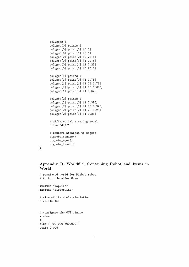
polygons 3polygon[0].points 6polygon[0].point[0] [0 0]polygon[0].point[1] [0 1]polygon[0].point[2] [0.75 1]polygon[0].point[3] [1 0.75]polygon[0].point[4] [1 0.25]polygon[0].point[5] [0.75 0]
polygon[1].points 4polygon[1].point[0] [1 0.75]polygon[1].point[1] [1.25 0.75]polygon[1].point[2] [1.25 0.625]polygon[1].point[3] [1 0.625]
polygon[2].points 4polygon[2].point[0] [1 0.375]polygon[2].point[1] [1.25 0.375]polygon[2].point[2] [1.25 0.25]polygon[2].point[3] [1 0.25]
# differential steering modeldrive "diff"
# sensors attached to bigbobbigbobs_sonars()bigbobs_eyes()bigbobs_laser()
)
Appendix B. Worldfile, Containing Robot and Items inWorld
# populated world for Bigbob robot# Author: Jennifer Owen
include "map.inc"include "bigbob.inc"
# size of the whole simulationsize [15 15]
# configure the GUI windowwindow(size [ 700.000 700.000 ]scale 0.025
61
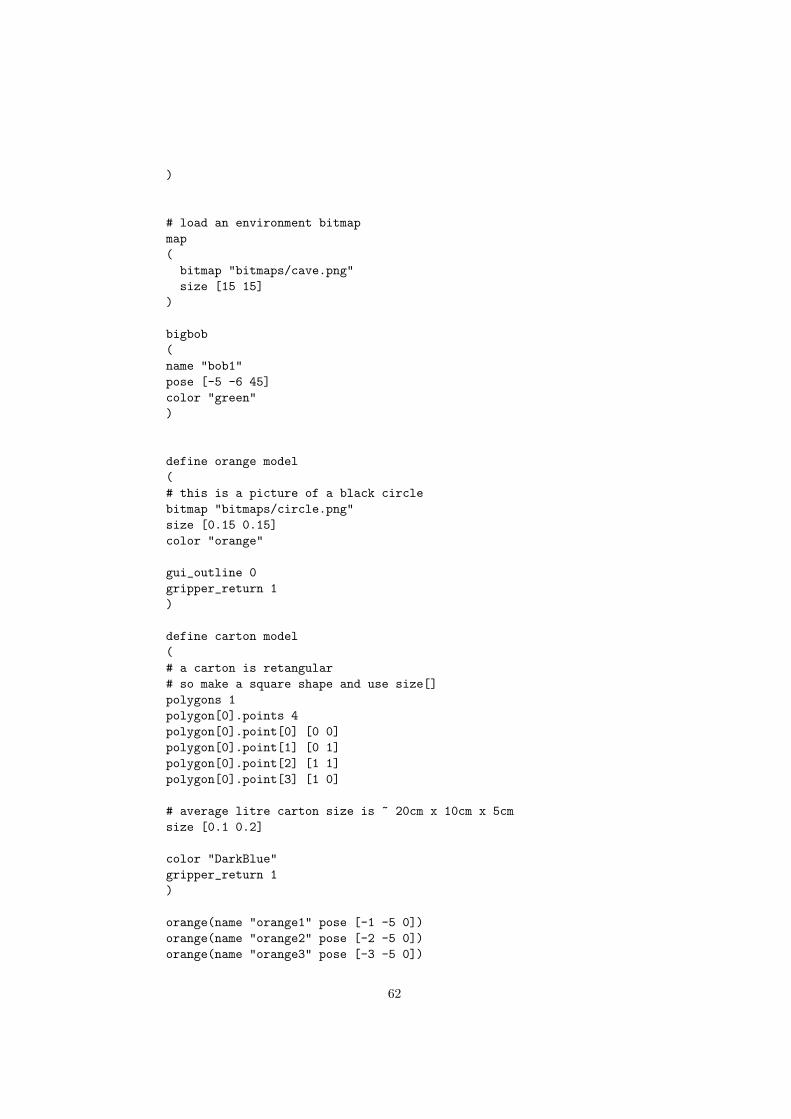
)
# load an environment bitmapmap(bitmap "bitmaps/cave.png"size [15 15]
)
bigbob(name "bob1"pose [-5 -6 45]color "green")
define orange model(# this is a picture of a black circlebitmap "bitmaps/circle.png"size [0.15 0.15]color "orange"
gui_outline 0gripper_return 1)
define carton model(# a carton is retangular# so make a square shape and use size[]polygons 1polygon[0].points 4polygon[0].point[0] [0 0]polygon[0].point[1] [0 1]polygon[0].point[2] [1 1]polygon[0].point[3] [1 0]
# average litre carton size is ~ 20cm x 10cm x 5cmsize [0.1 0.2]
color "DarkBlue"gripper_return 1)
orange(name "orange1" pose [-1 -5 0])orange(name "orange2" pose [-2 -5 0])orange(name "orange3" pose [-3 -5 0])
62

orange(name "orange4" pose [-4 -5 0])
carton(name "carton1" pose [-2 -4 0])carton(name "carton2" pose [-2 -3 0])carton(name "carton3" pose [-2 -2 0])carton(name "carton4" pose [-2 -1 0])
Appendix C. Configuration file for Bigbob World
# Desc: Player sample configuration file for controlling Stage devices# Author: Jennifer Owen# Date: 22/05/2009
driver(name "stage"plugin "libstageplugin"
provides ["simulation:0"]
# load the named file into the simulatorworldfile "robots_and_junk.world"
)
# the main bob1 robotdriver(
name "stage"provides [
"6665:position2d:0""6665:sonar:0""6665:blobfinder:0""6665:laser:0"]
model "bob1")
Appendix D. Controlling Code for Bigbob Robot Simula-tion
#include <stdio.h>#include <unistd.h>#include <time.h>#include <libplayerc++/playerc++.h>
63

struct Item{
char name[16];double x;double y;
}typedef item_t;
using namespace PlayerCc;
/**Randomly assigns new speeds into the given addresses.This function will always write to the given addresses.@param *forwardSpeed the address of the forward speedvariable you want this function to change.@param *turnSpeed the address of the turn speed variableyou want this function to change.*/void Wander(double *forwardSpeed, double *turnSpeed){
int maxSpeed = 1;int maxTurn = 90;double fspeed, tspeed;
//fspeed is between 0 and 10fspeed = rand()%11;//(fspeed/10) is between 0 and 1fspeed = (fspeed/10)*maxSpeed;
tspeed = rand()%(2*maxTurn);tspeed = tspeed-maxTurn;
*forwardSpeed = fspeed;*turnSpeed = tspeed;
}
/**Checks sonars for obstacles and updates the given addresseswith wheel speeds. This function will write to the addressesonly if there is an obstacle present. Very basic obstacle avoidance only.@param *forwardSpeed the address of the forward speed variableyou want this function to change.@param *turnSpeed the address of the turn speed variable youwant this function to change.@param &sp The sonar proxy that you want this function to monitor.*/void AvoidObstacles(double *forwardSpeed, double *turnSpeed, \
SonarProxy &sp)
64
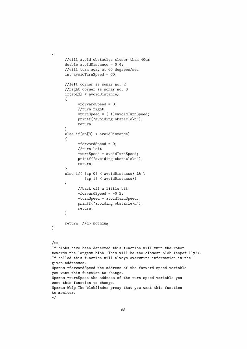
{//will avoid obstacles closer than 40cmdouble avoidDistance = 0.4;//will turn away at 60 degrees/secint avoidTurnSpeed = 60;
//left corner is sonar no. 2//right corner is sonar no. 3if(sp[2] < avoidDistance){
*forwardSpeed = 0;//turn right*turnSpeed = (-1)*avoidTurnSpeed;printf("avoiding obstacle\n");return;
}else if(sp[3] < avoidDistance){
*forwardSpeed = 0;//turn left*turnSpeed = avoidTurnSpeed;printf("avoiding obstacle\n");return;
}else if( (sp[0] < avoidDistance) && \
(sp[1] < avoidDistance)){
//back off a little bit*forwardSpeed = -0.2;*turnSpeed = avoidTurnSpeed;printf("avoiding obstacle\n");return;
}
return; //do nothing}
/**If blobs have been detected this function will turn the robottowards the largest blob. This will be the closest blob (hopefully!).If called this function will always overwrite information in thegiven addresses.@param *forwardSpeed the address of the forward speed variableyou want this function to change.@param *turnSpeed the address of the turn speed variable youwant this function to change.@param &bfp The blobfinder proxy that you want this functionto monitor.*/
65

void MoveToItem(double *forwardSpeed, double *turnSpeed, \BlobfinderProxy &bfp)
{int i, centre;int noBlobs = bfp.GetCount();playerc_blobfinder_blob_t blob;int turningSpeed = 10;
/*number of pixels away from the image centre a blobcan be to be in front of the robot*/int margin = 10;
int biggestBlobArea = 0;int biggestBlob = 0;
//find the largest blobfor(i=0; i<noBlobs; i++){
//get blob from proxyplayerc_blobfinder_blob_t currBlob = bfp[i];
if(currBlob.area > biggestBlobArea){
biggestBlob = i;biggestBlobArea = currBlob.area;
}}blob = bfp[biggestBlob];
// find centre of imagecentre = bfp.GetWidth()/2;
//adjust turn to centre the blob in image/*if the blob’s centre is within some margin of the imagecentre then move forwards, otherwise turn so that it iscentred. *///blob to the left of centreif(blob.x < centre-margin){
*forwardSpeed = 0;//turn left*turnSpeed = turningSpeed;
}//blob to the right of centreelse if(blob.x > centre+margin){
*forwardSpeed = 0;//turn right*turnSpeed = -turningSpeed;
}
66

//otherwise go straight aheadelse{
*forwardSpeed = 0.5;*turnSpeed = 0;
}
return;}
/**Fills the item list array with the names and positions of itemsin the simulation@param itemList this is the item list which contains the namesand positions of all the items in the simulation.@param simProxy the simulation proxy for the Player/Stage simulation.*/void RefreshItemList(item_t *itemList, SimulationProxy &simProxy){
int i;
//get the poses of the orangesfor(i=0;i<4;i++){
char orangeStr[] = "orange%d";sprintf(itemList[i].name, orangeStr, i+1);double dummy; //dummy variable, don’t need yaws.simProxy.GetPose2d(itemList[i].name, \
itemList[i].x, itemList[i].y, dummy);}
//get the poses of the cartonsfor(i=4;i<8;i++){
char cartonStr[] = "carton%d";sprintf(itemList[i].name, cartonStr, i-3);double dummy; //dummy variable, don’t need yaws.simProxy.GetPose2d(itemList[i].name, \
itemList[i].x, itemList[i].y, dummy);}
return;}
67

/**Finds an item in the simulation which is near the robot’s teeth.@param itemList this is the item list which contains the names andpositions of all the items in the simulation.@param listLength The number of items in the simulation@param sim the simulation proxy for the Player/Stage simulation.@return returns the index of the item in the array which is withinthe robot’s teeth. If no item is found then this will return -1.*/int FindItem(item_t *itemList, int listLength, SimulationProxy &sim){
double radius = 0.375;double distBotToCircle = 0.625;double robotX, robotY, robotYaw;double circleX, circleY;
//find the robot...sim.GetPose2d((char*)"bob1", robotX, robotY, robotYaw);
/*now we find the centre of the search circle.this is distBotToCircle metres from the robot’s originalong its yaw*/
/*horizontal offset from robot origin*/circleX = distBotToCircle*cos(robotYaw);
/*vertical offset from robot origin*/circleY = distBotToCircle*sin(robotYaw);
//find actual centre relative to simulation.circleX = robotX + circleX;circleY = robotY + circleY;
/* to find which items are within this circle wefind their Euclidian distance to the circle centre.Find the closest one and if it’s distance is smaller thanthe circle radius then return its index */
double smallestDist = 1000000;int closestItem = 0;int i;
for(i=0; i<listLength; i++){
double x, y, dist;x = circleX - itemList[i].x;y = circleY - itemList[i].y;
//find euclidian distance
68

dist = (x*x) + (y*y);dist = sqrt(dist);
if(dist < smallestDist){
smallestDist = dist;closestItem = i;
}}
return closestItem;}
int main(int argc, char *argv[]){
/*need to do this line in c++ only*/using namespace PlayerCc;
PlayerClient robot("localhost", 6665);
Position2dProxy p2dProxy(&robot,0);SonarProxy sonarProxy(&robot,0);BlobfinderProxy blobProxy(&robot,0);LaserProxy laserProxy(&robot,0);SimulationProxy simProxy(&robot,0);
double forwardSpeed, turnSpeed;item_t itemList[8];
RefreshItemList(itemList, simProxy);
srand(time(NULL));
//enable motorsp2dProxy.SetMotorEnable(1);
//request geometriesp2dProxy.RequestGeom();sonarProxy.RequestGeom();laserProxy.RequestGeom();//blobfinder doesn’t have geometry
/*here so that laserProxy[90] doesn’t segfault on first loop*/robot.Read();
while(true){
// read from the proxies
69

robot.Read();
if(blobProxy.GetCount() == 0){
//wanderprintf("wandering\n");Wander(&forwardSpeed, &turnSpeed);
}else{
//move towards the itemprintf("moving to item\n");MoveToItem(&forwardSpeed, &turnSpeed, blobProxy);
}
if(laserProxy[90] < 0.25){
int destroyThis;
destroyThis = FindItem(itemList, 8, simProxy);//move it out of the simulationprintf("collecting item\n");simProxy.SetPose2d(itemList[destroyThis].name, -10, -10, 0);RefreshItemList(itemList, simProxy);
}//avoid obstaclesAvoidObstacles(&forwardSpeed, &turnSpeed, sonarProxy);
//set motorsp2dProxy.SetSpeed(forwardSpeed, dtor(turnSpeed));sleep(1);
}}
70


![How to Use - Sony · 2017. 1. 16. · Hi-Res Audio Player How to Use Preparations What you can do with Hi-Res Audio Player Features of Hi-Res Audio Player [1] Prep 1: Installation](https://static.fdocuments.in/doc/165x107/60a0f1e105c5fe44b05582fa/how-to-use-sony-2017-1-16-hi-res-audio-player-how-to-use-preparations-what.jpg)


