How to Network Brochure - Leonardo 2010
74
1
Transcript of How to Network Brochure - Leonardo 2010

8/8/2019 How to Network Brochure - Leonardo 2010
http://slidepdf.com/reader/full/how-to-network-brochure-leonardo-2010 1/74
1

8/8/2019 How to Network Brochure - Leonardo 2010
http://slidepdf.com/reader/full/how-to-network-brochure-leonardo-2010 2/74
2
SUMMARY:
CHAPTER I: Basics of networking, advantages, usabilities<<<<<<<<..3 CHAPTER II: The history of the Internet and the DNS<<<<<<<<<..12
CHAPTER III: Connectors, switches and routers<<<<<<<<<<<...25
CHAPTER IV: Network topologies<<<<<<<<<<<<<<<<<...33
CHAPTER V: Building a simple network with several computers on Windows
Operating System. Connecting a Linux based computer to a Local Area
Network<<<<<<<<<<<<<<<<<<<<<<<<<<<<<<43
APPENDIX I: Technical terms and explanations<<<<<<<<<<<<..57
APPENDIX II: The OSI Model<<<<<<<<<<<<<<<<<<<<.66APPENDIX III: Bibliography<<<<<<<<<<<<<<<<<<<<<70
APPENDIX IV: Editorial Staff<<<<<<<<<<<<<<<<<<<<..72

8/8/2019 How to Network Brochure - Leonardo 2010
http://slidepdf.com/reader/full/how-to-network-brochure-leonardo-2010 3/74
3
CHAPTER I: Basics of networking,
advantages, usabilities
8/8/2019 How to Network Brochure - Leonardo 2010
http://slidepdf.com/reader/full/how-to-network-brochure-leonardo-2010 4/74
4
1.1 Definition
When thinking of a network the main word is ‚interconnected‛. That refersto the fact that a series of systems - meaning computers and other devices - are
able to communicate among themselves
and share resources using communication
paths or channels.
This concept was initially conceived
by the Advanced Research Projects
Agency that started funding the design ofthe first computer network in the world
for the United States Department of
Defense. The event happened in the beginning of the 1960s which led to the
development of network, starting in 1969.
1.2. Connections between computers. Peer to Peer Vs. Client-Server networks
Peer to Peer and Client-Server are the two basic concepts of networking,each describing a particular architecture. Because network access is not only
needed, but required, a Network Operating System, or NOS is installed onto
each PC in order to control the flow of information between users.
Peer to Peer
A peer to peer network allows 2 or more PCs
to share tasks or work loads between peers. Peersare equally privileged and due to that, individual
resources such as disk drives, CD-ROM drives
and even printers, turn into shared devices that
can be accessed from every PC, without the need
for central coordination by servers or stable hosts.

8/8/2019 How to Network Brochure - Leonardo 2010
http://slidepdf.com/reader/full/how-to-network-brochure-leonardo-2010 5/74
5
That means that all computers in the network can communicate directly to each
other and share all the resources. Peer-to-peer networks are appropriate only for
very small businesses or for home use because of the fact that they can only
support about 10 clients properly before getting overloaded. The systems used in
this type of network usually go up to Windows 2000 Professional.
For example, a Linux system would be unnecessary because there isn’t a
master computer.
Therefore, each client functions both as a client and as a server
simultaneously. Most NOSs allow each peer-to-peer user to determine which
resources will be available for use by other users. That means that if one user's
disk has been configured so that it is "shared", it will usually appear as a new
drive to the other users. Since users are allowed to control access to the resources
on their own computers, security becomes very risky in a peer-to-peerenvironment. There’s no central security or any way to control who shares what.
Users are free to create any network share points on their computers. The only
security on a peer-to-peer network is at the share level. When users create
network shares, they may implement no security, which means that anyone can
have full access to the share, or they may set a password on the share.
Depending on which networking platform you use, a user may be able to set
password to a share for read-only access and another password for full control
over the share.
Advantages:
There are more resources available to serve each user than in a Client
Server network;
There is no need for a network administrator;
Network is fast/inexpensive to setup & maintain;
Each PC can make backup copies of its data to other PCs for security; Easiest type of network to build, peer-to-peer is perfect for both home and
office use.

8/8/2019 How to Network Brochure - Leonardo 2010
http://slidepdf.com/reader/full/how-to-network-brochure-leonardo-2010 6/74
6
Drawbacks:
The network isn’t as secure as it seems to be;
The system is not centralised, making administration difficult;
Viruses can easily infiltrate into the system;
Backup has to be performed on each computer separately.
Client-server
The Client Server type of network divides
and distributes the tasks between servers,
which provide resources or services, and
clients, the service requesters. A servermachine is a host that is running one or more
server applications which share their
resources with clients. A client does not share
any of its resources, but requests the server's content or a service function.
Often clients and servers communicate over a computer network on separate
hardware, but both client and server may reside in the same system. A server
machine is a host that is running one or more server programs which share theirresources with clients
The server component provides a function or service to one or many clients,
which initiate requests for such services.
Comparison to peer-to-peer architecture
In peer-to-peer architectures, each host or instance of an application can
simultaneously act both as a client and a server, and each has equal
responsibilities and status. Both client-server and peer-to-peer architectures are
widely used today.
8/8/2019 How to Network Brochure - Leonardo 2010
http://slidepdf.com/reader/full/how-to-network-brochure-leonardo-2010 7/74
7
Advantages
Compared to peer to peer, client-server has a central server;
In most of the cases, a client-server architecture enables the roles and
responsibilities of a computing system to be distributed among severalindependent computers that are known to each other only through a network;
It functions with multiple different clients of different capabilities.
Disadvantages
As the number of simultaneous client requests to a given server increases,
the server can become overloaded;
Can have a single point of failure; Generally more expensive and difficult to set up initially.
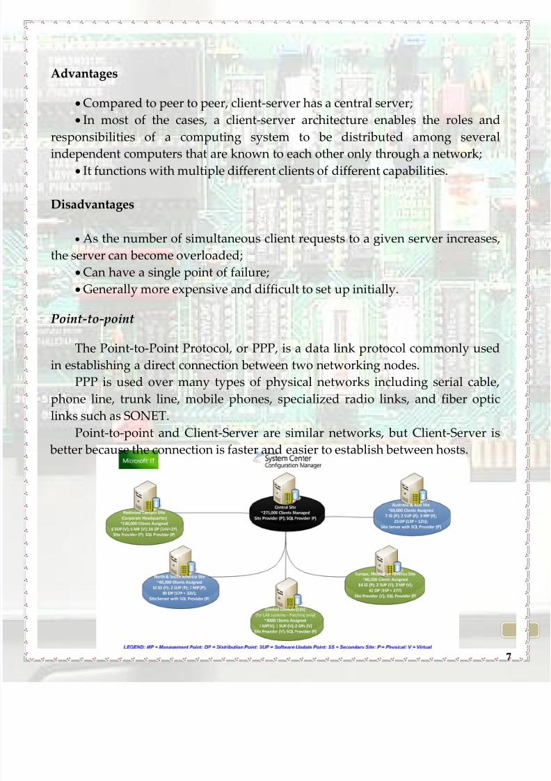
Point-to-point
The Point-to-Point Protocol, or PPP, is a data link protocol commonly used
in establishing a direct connection between two networking nodes.
PPP is used over many types of physical networks including serial cable,
phone line, trunk line, mobile phones, specialized radio links, and fiber optic
links such as SONET.
Point-to-point and Client-Server are similar networks, but Client-Server is
better because the connection is faster and easier to establish between hosts.
8/8/2019 How to Network Brochure - Leonardo 2010
http://slidepdf.com/reader/full/how-to-network-brochure-leonardo-2010 8/74
8
1.3. Classification of the Networks
a) Depending on their scales , usage and purpose , networks can be classified:
PAN (Personal Area N etwork) is used for communication between a computer and
different devices in a restricted area, that can be wired or wireless, such as
printers, scanners, fax machines, PDAs, telephones or video game consoles. The
reach of PAN typically extends to 10 meters.
LAN (Local Area N etwork) connects computers and devices that are placed in
certain buildings such as home, schools, computer laboratories, office buildings.
Each computer or device on the network is a node. The connections can be alsowired or wireless with a bandwidth of 100 Mbps.
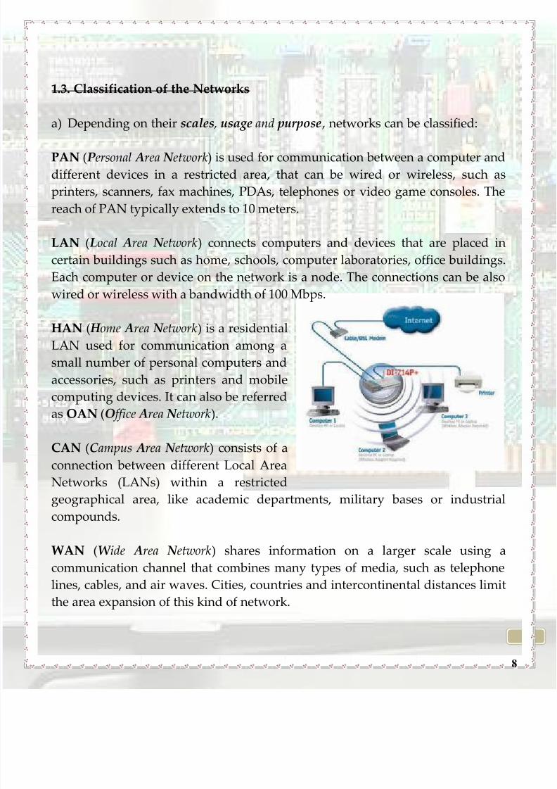
HAN ( H ome Area N etwork) is a residential
LAN used for communication among a
small number of personal computers and
accessories, such as printers and mobile
computing devices. It can also be referred
as OAN (O ffice Area N etwork).
CAN (Campus Area N etwork) consists of a
connection between different Local Area
Networks (LANs) within a restricted
geographical area, like academic departments, military bases or industrial
compounds.
WAN (W ide Area N etwork) shares information on a larger scale using acommunication channel that combines many types of media, such as telephone
lines, cables, and air waves. Cities, countries and intercontinental distances limit
the area expansion of this kind of network.

8/8/2019 How to Network Brochure - Leonardo 2010
http://slidepdf.com/reader/full/how-to-network-brochure-leonardo-2010 9/74
9
GAN (Global Area N etwork) is a network used for supporting mobile
communications across an arbitrary number of wireless LANs, satellite coverage
areas. It involves a succession of terrestrial
wireless local area networks (WLAN).
EPN (Enterprise Private N etwork)
interconnects divers company sites, such as
production sites, head offices, remote offices
or shops for the purpose of sharing
computer resources.
VPN (V irtual Private N etwork) is a computer
network in which some of the links betweennodes are carried by open connections or
virtual circuits in some larger network, like
the Internet, instead of by physical wires.
b) Depending on the connection method , the network can be classified:
A. Wired: Computers are interconnected with cables.
B. Wireless:
You can connect 2 or more devices without any cables in numerous ways:
a) via Infrared: which can transmit signals between devices within small
distances not more than 10 meters peer to peer or (face to face)
without any body in the line of transmitting.
b) Via Bluetooth: is an open wireless technology standard for
exchanging data over short distances creating personal area
networks (PANs) with high levels of security.
8/8/2019 How to Network Brochure - Leonardo 2010
http://slidepdf.com/reader/full/how-to-network-brochure-leonardo-2010 10/74
10
c) Wi-Fi: A Wi-Fi enabled device such as a personal
computer, video game console, mobile phone, MP3
player or personal digital assistant can connect to the
Internet when within range of a wireless network
connected to the Internet.
1.6. Advantages
File sharing - files and data can be directly shared using a network, with
no need for CDs/DVDs or USB flash drives. The distance is not an obstacle, as the
information from one PC to another can be easily sent.
Software costs - the prices of lots of software are lower if bought for theentire network comparing to purchasing them individually. Upgrades are also
easier because changes only have to be done once on the file server instead of on
individual workstations.
Security - certain folders can be protected by a password to limit the access
to authorized users. Important files on a network can be designed as ‚copy
inhibit‛ in order to avoid illegal copy of applications or other media resources.
Resource Sharing - all the computers on a network can share the same
resources, such as printers, fax machines, scanners or modems.
Communication - using the electronic mail, those on the network can
communicate with each other even outside of the internet.
Speed - file transfer speed between those on the network is much higher.
Flexible access - files from computers can be accessed by users throughout
the network. A user can change computers in order to finish his work. Multiple
users can collaborate on the same project through the network.
8/8/2019 How to Network Brochure - Leonardo 2010
http://slidepdf.com/reader/full/how-to-network-brochure-leonardo-2010 11/74
11
Workgroup Computing - workgroup software like Microsoft BackOffice
enables many users to contribute to a document concurrently. This allows for
interactive teamwork.
1.7. Usabilities
Networks have various usabilities in different domains.
1.Education Units , characterized by academic networks (Campus Area
Network) . In the case of a university campus-based campus, the network links a
variety of campus buildings including; academic departments, the university
library and student residence halls. CAN networks have been created to facilitate
student access to the Internet and university resources. Same usability exists inthe pre-university education.
2.In the private domain (home), in which a network is used for
communication between digital devices typically deployed in the home, usually
a small number of personal computers and accessories, such as printers and
mobile computing devices. An important function is the sharing of Internet
access, often a broadband service through a CATV provider.
3.In the enterprise domain , in which a network built by an enterpriseinterconnects various company sites, e.g., production websites, head offices,
remote offices, shops, in order to share computer resources.

8/8/2019 How to Network Brochure - Leonardo 2010
http://slidepdf.com/reader/full/how-to-network-brochure-leonardo-2010 12/74
12
CHAPTER II: The history of the Internet
and the DNS
8/8/2019 How to Network Brochure - Leonardo 2010
http://slidepdf.com/reader/full/how-to-network-brochure-leonardo-2010 13/74
13
What does the Internet mean?
The Internet is a global system of interconnected computer networks that
use the standard Internet Protocol Suite (TCP/IP) to serve billions of users
worldwide. It is a network of networks that consists of millions of private, public,
academic, business, and government networks of local to global scope that are
linked by a broad array of electronic and optical networking technologies. The
Internet carries a vast array of information resources and services, most notably
the inter-linked hypertext documents of the World Wide Web (WWW) and the
infrastructure to support electronic mail.
When, how, why did the Internet appear?
The start of internet development was the actual competition between two
greatest powers of the XX century, U.S.A and U.R.S.S. In 1957, U.R.S.S launches
the first artificial earth satellite into the outer space named Sputnik. This fact
created a big concern on the U.S.A and that's why the president of U.S.A
founded a special agency subordinated to the Pentagon (www.darpa.mil) . This
agency of the department of defence was conducted by science men and has the
mission of keeping the technological superiority of the U.S.A army by
sponsoring the most revolutionary scientific discoveries and by the investment ofunlimited founds for the creation of a bound between the scientific research and
the military technological implementation of it.
8/8/2019 How to Network Brochure - Leonardo 2010
http://slidepdf.com/reader/full/how-to-network-brochure-leonardo-2010 14/74
14

8/8/2019 How to Network Brochure - Leonardo 2010
http://slidepdf.com/reader/full/how-to-network-brochure-leonardo-2010 15/74
15
What is DARPA?
The Defense Advanced Research Projects A gency (DARPA) is an agency of the
United States Department of Defense responsible for the development of new
technology for use by the military. DARPA has been responsible for funding the
development of many technologies which have had a major effect on the world,
including computer networking, as well as NLS, which was both the first
hypertext system, and an important precursor to the contemporary ubiquitous
graphical user interface. Its original name was simply Advanced Research Projects
A gency (ARPA), but it was renamed DARPA (for Defense) during March 1972,
then renamed ARPA again during February 1993, and then renamed DARPA
again during March 1996.
DARPA was established during 1958 (as ARPA) in response to the Sovietlaunching of Sputnik during 1957, with the mission of keeping U.S. military
technology more sophisticated than that of the nation's potential enemies. From
DARPA's own introduction. DARPA’s original mission, established in 1958, was
to prevent technological surprise like the launch of Sputnik, which signaled that
the Soviets had beaten the U.S. into space. The mission statement has evolved
over time. Today, DARPA’s mission is still to prevent technological surprise to
the US, but also to create technological surprise for its enemies.
How did the ARPANET network function?
After much work, the first two nodes of what would become the
ARPANET were interconnected between Kleinrock's Network Measurement
Center at the UCLA's School of Engineering and Applied Science and Douglas
Engelbart's NLS system at SRI International (SRI) in Menlo Park, California, on
29 October 1969. The third site on the ARPANET was the Culler-Fried Interactive
Mathematics centre at the University of California at Santa Barbara, and thefourth was the University of Utah Graphics Department. In an early sign of
future growth, there were already fifteen sites connected to the young
ARPANET by the end of 1971. All of these were coded in a protocol which could
regulate the transmission of data. In it’s final form this was TCP/IP
(Transmission Control Protocol / Internet Protocol) created by Vint Cerf and
8/8/2019 How to Network Brochure - Leonardo 2010
http://slidepdf.com/reader/full/how-to-network-brochure-leonardo-2010 16/74
16
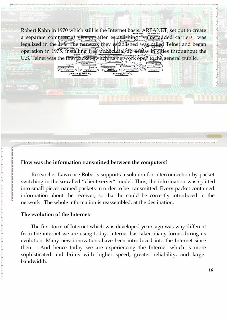
Robert Kahn in 1970 which still is the Internet basis. ARPANET, set out to create
a separate commercial version after establishing "value added carriers" was
legalized in the U.S. The network they established was called Telnet and began
operation in 1975, installing free public dial-up access in cities throughout the
U.S. Telnet was the first packet-switching network open to the general public.
How was the information transmitted between the computers?
Researcher Lawrence Roberts supports a solution for interconnection by packe
switching in the so-called ‘‘client-server‛ model. Thus, the information was splitte
into small pieces named packets in order to be transmitted. Every packet contained
information about the receiver, so that he could be correctly introduced in th
network . The whole information is reassembled, at the destination.
The evolution of the Internet:
The first form of Internet which was developed years ago was way differentfrom the internet we are using today. Internet has taken many forms during its
evolution. Many new innovations have been introduced into the Internet since
then – And hence today we are experiencing the Internet which is more
sophisticated and brims with higher speed, greater reliability, and larger
bandwidth.
8/8/2019 How to Network Brochure - Leonardo 2010
http://slidepdf.com/reader/full/how-to-network-brochure-leonardo-2010 17/74
17
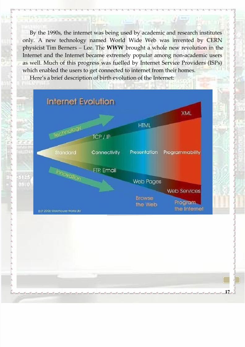
By the 1990s, the internet was being used by academic and research institutes
only. A new technology named World Wide Web was invented by CERN
physicist Tim Berners – Lee. The WWW brought a whole new revolution in the
Internet and the Internet became extremely popular among non-academic users
as well. Much of this progress was fuelled by Internet Service Providers (ISPs)
which enabled the users to get connected to internet from their homes.
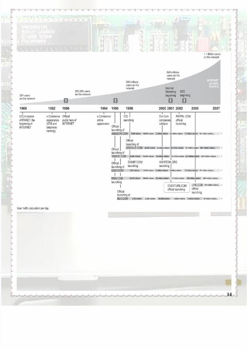
Here’s a brief description of birth evolution of the Internet:
8/8/2019 How to Network Brochure - Leonardo 2010
http://slidepdf.com/reader/full/how-to-network-brochure-leonardo-2010 18/74
18
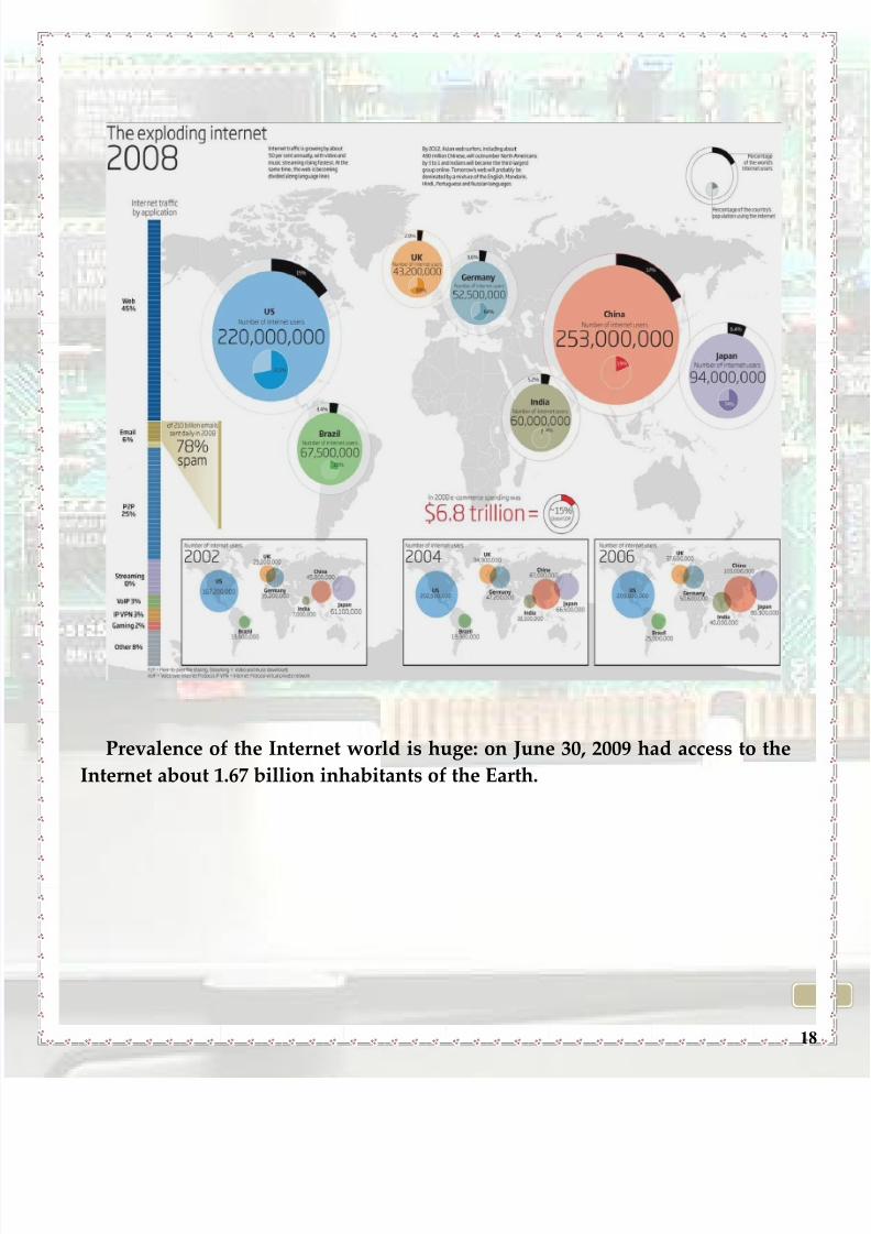
Prevalence of the Internet world is huge: on June 30, 2009 had access to the
Internet about 1.67 billion inhabitants of the Earth.
8/8/2019 How to Network Brochure - Leonardo 2010
http://slidepdf.com/reader/full/how-to-network-brochure-leonardo-2010 19/74
19
THE HISTORY OF THE DNS
What were the origins of the DNS?
The Domain Name System was originally invented to support the growth of
email communications on the ARPANET, and now supports the Internet on a
global scale. Alphabetic host names were introduced on the ARPANET shortly
after its creation, and greatly increased usability since alphabetic names are
much easier to remember than semantically meaningless numeric addresses.
Host names were also useful for development of network-aware computer
programs, since they could reference a constant host name without concern
about changes to the physical address due to network alterations. Of course, the
infrastructure of the underlying network was still based on numeric addresses,so each site maintained a "HOSTS.TXT" file that provided a mapping between
host names and network addresses in a set of simple text records that could be
easily read by a person or program.
Was the system efficient enough?
It wasn't long before people realized that keeping multiple copies of the hosts
file was inefficient and error-prone. Starting with a formal proposal forcentralization in Host Names On-line, RFC 606, in December, 1973, proceeding
through agreement in Host Names On-Line, RFC 608, and further discussions
and comments on On-Line Host Name Service, RFC 623, it was settled by March,
1974 with On Line Hostnames Service, RFC 625, that the Stanford Research
Institute Network Information Center (NIC) would serve as the official source of
the master hosts file. This centralized system worked well for about a decade,
approximately 1973 to 1983. However, by the early 1980's the disadvantages of
centralized management of a large amount of dynamic data were becomingapparent. The hosts file was becoming larger, the rate of change was growing as
the network expanded, more hosts were downloading the entire file nightly, and
there were always errors that were then propagated network-wide. Change was
required, but a spark was needed. A group of ARPANET researchers, principles,
and related parties held a meeting in January, 1982, to discuss a solution for

8/8/2019 How to Network Brochure - Leonardo 2010
http://slidepdf.com/reader/full/how-to-network-brochure-leonardo-2010 20/74
20
email relaying. As described on the email addresses page, email was often
originally sent from site to site to its destination along a path of systems, and
might need to go through a half a dozen or more links that would connect at
certain times of the day. For example, the following actual communication path
shows individual systems separated by "!",with the destination user named "grg"
tagged on at the end.
utzoo!decvax!harpo!eagle!mhtsa!ihnss!ihuxp!grg.
What is 'BIND'?
The application that runs almost every DNS server on the Internet is called
BIND, for Berkeley Internet Name Domain, first developed as a graduate student
project at the University of California at Berkeley, and maintained throughversion 4.8.3 by the university's Computer Systems Research Group
(CSRG).Versions 4.9 and 4.9.1 of BIND were released by then the number two
computer company, Digital Equipment Corporation. The lead developer was
Paul Vixie. After Vixie left to establish Vixie Enterprises, he sponsored the
development of BIND Version 4.9.2, and became the application's principal
architect. Versions 4.9.3 on have been developed and maintained by the Internet
Systems Consortium. A major architectural update called Version 8 was co-
developed by Bob Halley and Paul Vixie and released in May 1997. Anothermajor architectural rewrite called Version 9 with enhanced security support was
developed and released in the year 2000.
Did you know that…
In 1971 the first e-mail was sent between two computers. Tomlinson was the
one who created a program called SNDMSG who sent a simple email to a
computer near the ARPAnet network. He was the one who put the @ in your e-mail. The first e-mail address in the world was "Tomlinson @ bbn-tenexa. Tenexa
was the name of operating system you use, and BBN were the initials of an
employee's Tomlinson.

8/8/2019 How to Network Brochure - Leonardo 2010
http://slidepdf.com/reader/full/how-to-network-brochure-leonardo-2010 21/74
21
THE HISTORY OF WEB BROWSERS
What is a Web Browser?
A web browser is a software application whose aim is to download and
present the www (World Wide Web) resources. The information on www are
identified using URI (Uniform Resource Identifier). The best known browsers
nowadays are Internet Explorer, Mozilla Firefox, Google Chrome, Apple Safari
and Opera for Windows and Apple Safari, Mozilla Firefox and Opera for Mac.
How did the first Web Browser appear?
The history of web browsers started around the 80s when a variety of
technologies led to the first World Wide Web browser appearance. This browser
was rolling on the NEXTSTEP platform and was renamed Nexus to avoid the
confusion with World Wide Web. After that, ViolaWWW appeared. This was themost popular browser until 1993. It was the first browser to support embedded
scriptable objects, stylesheets, and tables. Both projects were influenced a lot by
the technological progress during the 80s when the appearance and development
of the Internet took place.

8/8/2019 How to Network Brochure - Leonardo 2010
http://slidepdf.com/reader/full/how-to-network-brochure-leonardo-2010 22/74
22
How did the browsers evolve?
Mosaic followed ViolaWWW. This browser was considered the first browser
with a graphical interface. It went through the FTP, Usenet and Gopher
protocols. The easily understood interface, the portability and the ease of
installation led to the raise of the number of clients. It was also the first browser
to show the pictures inside the page and not in other windows.
The most popular browsers within the MAC users remain Apple Safari in the
first place, followed by Firefox, Camino and Flock. Apart from that, one of the
most popular browsers within the Unix users remains Lynx, the oldest browser
until now. Google tried to create problems in this domain by launching Google
Chrome by the end of 2008, a browser which attracted almost 4% of the webusers, because of its ease and speed.
8/8/2019 How to Network Brochure - Leonardo 2010
http://slidepdf.com/reader/full/how-to-network-brochure-leonardo-2010 23/74
23
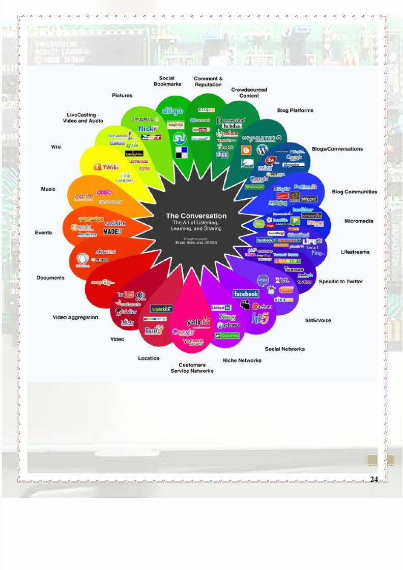
What is WEB 2.0?
The term web 2.0 is commonly associated with web applications that facilitate
interactive information sharing, interoperability, user-centered design, and
collaboration on the World Wide Web. A web 2.0 site gives its users the free
choice to interact or collaborate with each other in a social media dialogue as
creators of user-generated content in a virtual community, in contrast to websites
where users are limited to the passive viewing of content that was created for
them. Examples of Web 2.0 include social-networking sites, blogs, wikis, video-
sharing sites, hosted services, web applications, mashups and folksonomies.
The term is closely associated with Tim O'Reilly because of the O'Reilly Media
Web 2.0 conference in 2004. Although the term suggests a new version of the
World Wide Web, it does not refer to an update to any technical specifications, but rather to cumulative changes in the ways software developers and end-users
use the Web. Whether Web 2.0 is qualitatively different from prior web
technologies has been challenged by World Wide Web inventor Tim Berners-Lee,
who called the term a "piece of jargon", precisely because he intended the Web in
his vision as "a collaborative medium, a place where we [could] all meet and
read and write". He called it the 'Read/Write Web'.
8/8/2019 How to Network Brochure - Leonardo 2010
http://slidepdf.com/reader/full/how-to-network-brochure-leonardo-2010 24/74
24
8/8/2019 How to Network Brochure - Leonardo 2010
http://slidepdf.com/reader/full/how-to-network-brochure-leonardo-2010 25/74
25
CHAPTER III: Connectors, switches and
routers
8/8/2019 How to Network Brochure - Leonardo 2010
http://slidepdf.com/reader/full/how-to-network-brochure-leonardo-2010 26/74
26
I. Cables and connectors
A cable is represented by two or more wires running side by side and
bonded, twisted or braided together to form a single assembly.
There are many categories of cables you can use, according to the
transmission speed, the distances and the security you need to implement:
Coaxial cable
Twisted pair cable
Optical fiber
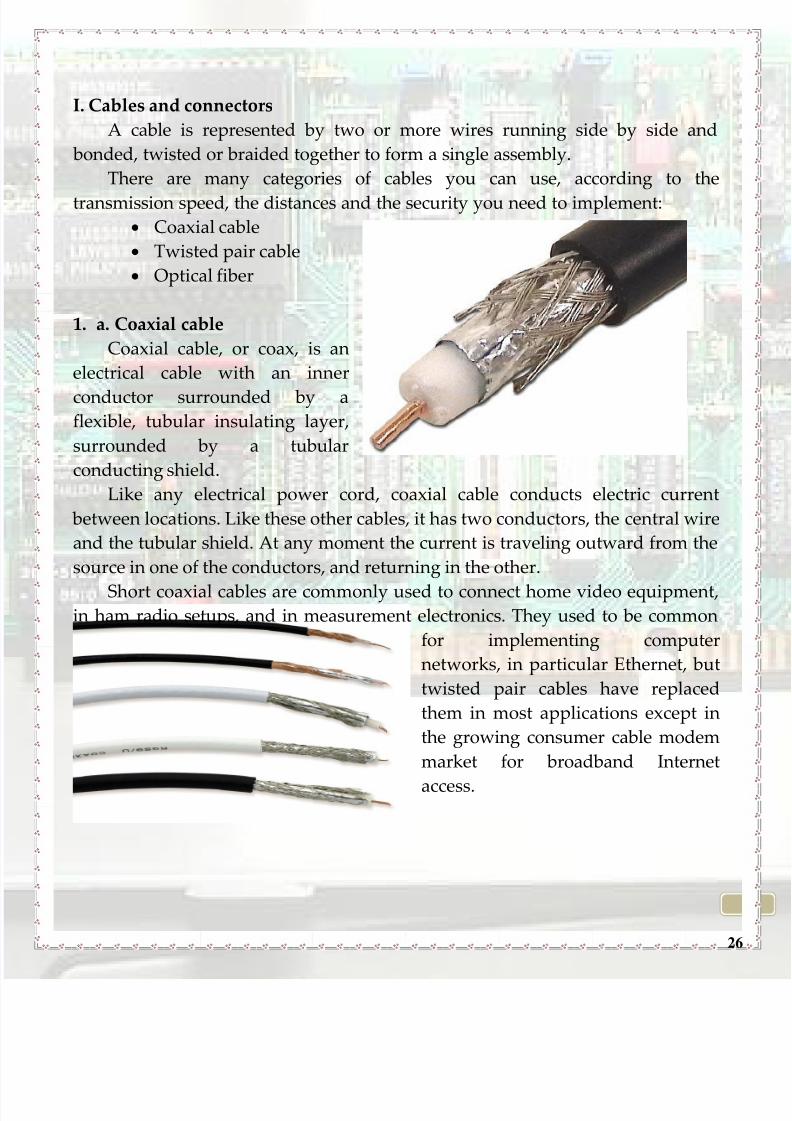
1. a. Coaxial cable
Coaxial cable, or coax, is an
electrical cable with an inner
conductor surrounded by aflexible, tubular insulating layer,
surrounded by a tubular
conducting shield.
Like any electrical power cord, coaxial cable conducts electric current
between locations. Like these other cables, it has two conductors, the central wire
and the tubular shield. At any moment the current is traveling outward from the
source in one of the conductors, and returning in the other.
Short coaxial cables are commonly used to connect home video equipment,in ham radio setups, and in measurement electronics. They used to be common
for implementing computer
networks, in particular Ethernet, but
twisted pair cables have replaced
them in most applications except in
the growing consumer cable modem
market for broadband Internet
access.

8/8/2019 How to Network Brochure - Leonardo 2010
http://slidepdf.com/reader/full/how-to-network-brochure-leonardo-2010 27/74
27
1. b. Coaxial connectors
Coaxial connectors are designed to maintain a coaxial
form across the connection and have the same well-defined
impedance as the attached cable.
2. Twisted cablesTwisted pair cabling is a type of wiring
in which two conductors (forward and
return conductors of a single circuit) are
twisted together for the purpose of
canceling out electromagnetic interference.
Twisted pair cabling comes in two
varieties: shielded and unshielded.
2. A. a. Unshielded twisted pair cable
Unshielded twisted pair (UTP) is the most popular and is generally the best
option for school networks.
The quality of UTP may vary from telephone-grade wire to extremely high-
speed cable. The cable has four pairs of wires inside the jacket. Each pair is
twisted with a different number of twists per inch to help eliminate interference
from adjacent pairs and other electrical devices. The tighter the twisting, the
higher the supported transmission rate.
8/8/2019 How to Network Brochure - Leonardo 2010
http://slidepdf.com/reader/full/how-to-network-brochure-leonardo-2010 28/74
28
Cat1* Analog voice (POTS), ISDN (one Pair) – 1Mhz up to 1Mbits/s;
Cat2* Mainly used in Token Ring networks
Cat 3 Bandwidth 16Mhz. Data carrying up to 10 Mbits/s
Cat 4 Used in 16Mbit/s Token Ring. Not used much.
Cat 5 A twisted pair high signal integrity cable. ‛Mostly unshielded‛
Cat 6 Standard provides performance up to 500Mhz and 10Gbit/s.
Cat 7 Features more specifications for crosstalk and system noise then
previous categories. Shielding was added for individual wire
pairs and the cable as a whole. Frequency up to 1000Mhz.
10Gbit/s at 100 meters. 40Gbit/s possible at 50 meters. 100Gbit/s
at 15 meters.
*All categories are backwards compatible.
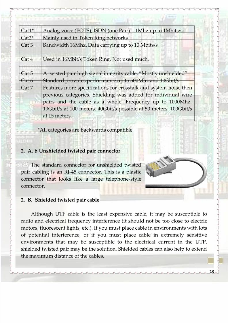
2. A. b Unshielded twisted pair connector
The standard connector for unshielded twisted
pair cabling is an RJ-45 connector. This is a plastic
connector that looks like a large telephone-style
connector.
2. B. Shielded twisted pair cable
Although UTP cable is the least expensive cable, it may be susceptible to
radio and electrical frequency interference (it should not be too close to electric
motors, fluorescent lights, etc.). If you must place cable in environments with lotsof potential interference, or if you must place cable in extremely sensitive
environments that may be susceptible to the electrical current in the UTP,
shielded twisted pair may be the solution. Shielded cables can also help to extend
the maximum distance of the cables.
8/8/2019 How to Network Brochure - Leonardo 2010
http://slidepdf.com/reader/full/how-to-network-brochure-leonardo-2010 29/74
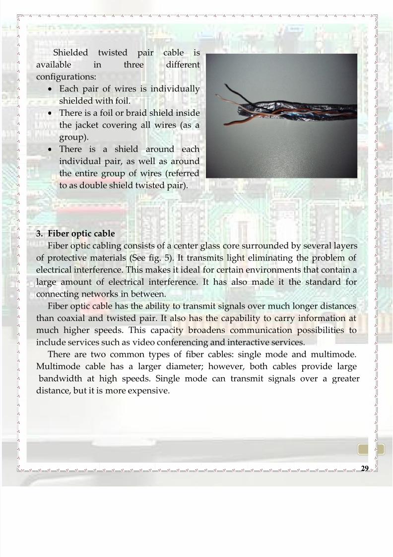
29
Shielded twisted pair cable is
available in three different
configurations:
Each pair of wires is individually
shielded with foil.
There is a foil or braid shield inside
the jacket covering all wires (as a
group).
There is a shield around each
individual pair, as well as around
the entire group of wires (referred
to as double shield twisted pair).
3. Fiber optic cable
Fiber optic cabling consists of a center glass core surrounded by several layers
of protective materials (See fig. 5). It transmits light eliminating the problem of
electrical interference. This makes it ideal for certain environments that contain a
large amount of electrical interference. It has also made it the standard for
connecting networks in between.Fiber optic cable has the ability to transmit signals over much longer distances
than coaxial and twisted pair. It also has the capability to carry information at
much higher speeds. This capacity broadens communication possibilities to
include services such as video conferencing and interactive services.
There are two common types of fiber cables: single mode and multimode.
Multimode cable has a larger diameter; however, both cables provide large
bandwidth at high speeds. Single mode can transmit signals over a greater
distance, but it is more expensive.

8/8/2019 How to Network Brochure - Leonardo 2010
http://slidepdf.com/reader/full/how-to-network-brochure-leonardo-2010 30/74
30
Installing Cables:
It is always recommended to use more cables than you need. You should
leave plenty of slack.
Every time you install a new part of the network, you should test it first.
There are problems that may occur even if that certain part is brand new. You should stay at least 1 meter away from sources of electrical
interference and fluorescent light boxes.
If the cable runs across the floor, cover it with cable protectors.
Label both ends of each cable.
In order to keep cables in the same location together, use cable ties.
II.Routers
A router represents the electronic device which is used for interconnectingand interchanging packets of data between two or more computer networks.
Routers are located at gateways, the places where two or more networks connect.
Routers connect two or more logical subnets, each having a different network
address.
8/8/2019 How to Network Brochure - Leonardo 2010
http://slidepdf.com/reader/full/how-to-network-brochure-leonardo-2010 31/74
31
Routers come in all sizes and shapes and are used for companies, houses,
businesses, ISPs themselves and many other things. The router is the only device
that enables you to see every message sent between the network. For the router
to decide where the package of data should go, it needs a configuration table,
which is a collection of information:
specifications on which connections lead to particular groups of addresses;
priorities for connections;
rules for handling both routine and special cases of traffic. The computer
you'd like to receive the message has to be connected to a router to be able
to communicate between the network.
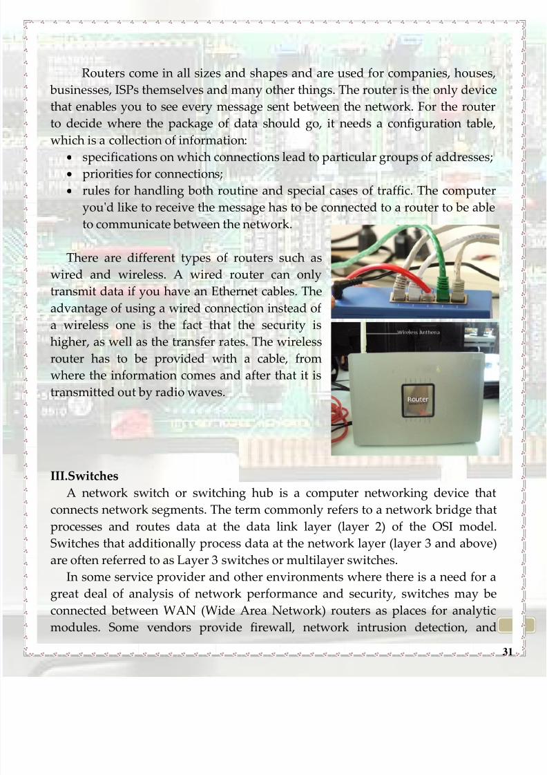
There are different types of routers such as
wired and wireless. A wired router can onlytransmit data if you have an Ethernet cables. The
advantage of using a wired connection instead of
a wireless one is the fact that the security is
higher, as well as the transfer rates. The wireless
router has to be provided with a cable, from
where the information comes and after that it is
transmitted out by radio waves.
III.Switches
A network switch or switching hub is a computer networking device that
connects network segments. The term commonly refers to a network bridge that
processes and routes data at the data link layer (layer 2) of the OSI model.
Switches that additionally process data at the network layer (layer 3 and above)are often referred to as Layer 3 switches or multilayer switches.
In some service provider and other environments where there is a need for a
great deal of analysis of network performance and security, switches may be
connected between WAN (Wide Area Network) routers as places for analytic
modules. Some vendors provide firewall, network intrusion detection, and

8/8/2019 How to Network Brochure - Leonardo 2010
http://slidepdf.com/reader/full/how-to-network-brochure-leonardo-2010 32/74
32
performance analysis modules that can plug into switch ports and help to secure
your network.
Switches are similar to network hubs and are usually included as part of a
router. However, switches prevent data packets from colliding with one another
in the network, unlike the hubs do.
The above switch can establish a connection between 24computers. A standard switch can have maximum 48 ports
and is used in big enterprises.
8/8/2019 How to Network Brochure - Leonardo 2010
http://slidepdf.com/reader/full/how-to-network-brochure-leonardo-2010 33/74
33
CHAPTER IV: NETWORK TOPOLOGIES

8/8/2019 How to Network Brochure - Leonardo 2010
http://slidepdf.com/reader/full/how-to-network-brochure-leonardo-2010 34/74
34
Network topology is defined as the interconnection of the various elements
(links, nodes, etc.) of a computer network.
There are two main categories of topologies:
Physical- the design of a network including the devices, location and cable
installation;
Logical - how data is actually transferred in a network as opposed to its
physical design.
BUS TOPOLOGY
A bus topology is a network architecture in which a set of clients are
connected via a shared communications line. A bus is usually referred as the
cable that connects end to end and this is used to transmit the signals.
Advantages
If one computer fails, the others are still not affected and they continue to
work;
It‘s easy to implement, to extend and to install; Well-suited for temporary or small networks: not requiring high speeds
(quick setup);
Cheaper than other topologies. Effective cost: only a single cable is used;
Easy identification of cable faults.

8/8/2019 How to Network Brochure - Leonardo 2010
http://slidepdf.com/reader/full/how-to-network-brochure-leonardo-2010 35/74
35
Disadvantages
If there is a problem with the cable, the entire network breaks down;
Performance degrades as additional computers are added or on heavy
traffic (shared bandwidth);
Proper termination is required (loop must be in closed path);
Significant Capacitive Load (each bus transaction must be able to stretch to
most distant link).
It works better with limited number of nodes.
Passivity – the computers on the bus are not responsible for moving the
signal along, they simply listen for a signal;
When a device sends it’s packet out over the bus, every other network card
on the bus sees and reads that packet;
Only one packet can remain on the bus during one clock pulse; When two cards send packets at the same time, it results a collision, and
the cards themselves arbitrate to decide which one will resend its packet
first.
STAR TOPOLOGY
A star network consists of one central switch, hub or computer, which acts
as a conduit to transmit messages. Thus, the switch, the leaf nodes, and the
transmission lines between them, form a graph with the topology of a star.

8/8/2019 How to Network Brochure - Leonardo 2010
http://slidepdf.com/reader/full/how-to-network-brochure-leonardo-2010 36/74
36
Advantages:
Higher performance: star topology prevents the passing of data packets
through an excessive number of nodes. At most, 3 devices and 2 links areinvolved in any communication between any two devices. Although this
topology places a huge overhead on the central switch, with adequate
capacity, the switch can handle very high utilization by one device without
affecting others;
Isolation of devices: Each device is inherently isolated by the link that
connects it to the switch. This makes the isolation of individual devices
straightforward and amounts to disconnecting each device from the others.
This isolation also prevents any non-centralized failure from affecting thenetwork;
Benefits from centralization: As the central switch is the bottleneck,
increasing it’s capacity, or connecting additional devices to it, you can
increase the size of the network very easily. Centralization also allows the
inspection of traffic through the network. This facilitates analysis of the
traffic and detection of suspicious behaviour;
Simplicity: This topology is easy to understand, establish, and navigate.
It’s simplicity obviates the need for complex routing or message passingprotocols. Also, as noted earlier, the isolation and centralization it allows
simplify fault detection, as each link or device can be probed individually;
Easy to install, to wire, to detect faults and to remove parts;
No disruptions to the network when connecting or removing devices.
Disadvantages:
The high dependence of the system on the functioning of the centralswitch. While the failure of an individual link only results in the isolation
of a single node, the failure of the central hub switch the network
inoperable, immediately isolating all nodes;
The performance and scalability of the network also depend on the
capabilities of the switch;
8/8/2019 How to Network Brochure - Leonardo 2010
http://slidepdf.com/reader/full/how-to-network-brochure-leonardo-2010 37/74
37
Network size is limited by the number of connections that can be made to
the hub, and performance for the entire network is capped by it’s
throughput;
Wiring up of the system can be very complex and high costing.
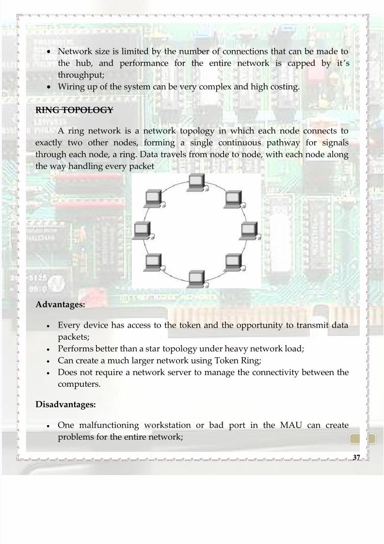
RING TOPOLOGY
A ring network is a network topology in which each node connects to
exactly two other nodes, forming a single continuous pathway for signals
through each node, a ring. Data travels from node to node, with each node along
the way handling every packet
Advantages:
Every device has access to the token and the opportunity to transmit data
packets;
Performs better than a star topology under heavy network load;
Can create a much larger network using Token Ring;
Does not require a network server to manage the connectivity between the
computers.
Disadvantages:
One malfunctioning workstation or bad port in the MAU can create
problems for the entire network;

8/8/2019 How to Network Brochure - Leonardo 2010
http://slidepdf.com/reader/full/how-to-network-brochure-leonardo-2010 38/74
38
Moves, adds and changes of devices can affect the network;
Network adapter cards and MAU's are much more expensive than
Ethernet cards and switches;
Much slower than an Ethernet network under normal load.
HYBRID TOPOLOGY
Hybrid networks use a combination of any two or more topologies in such
a way that the resulting network does not exhibit one of the standard topologies
(bus, star, ring, etc.). A hybrid topology is always produced when two different
basic network topologies are connected.
Advantages:
It can be designed in many ways for various purposes.
Disadvantages:
It is costly.
8/8/2019 How to Network Brochure - Leonardo 2010
http://slidepdf.com/reader/full/how-to-network-brochure-leonardo-2010 39/74
39
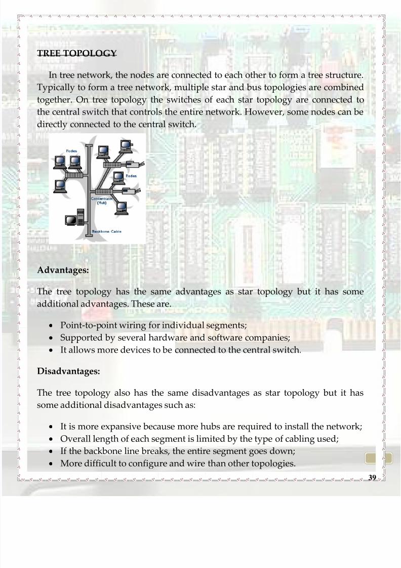
TREE TOPOLOGY
In tree network, the nodes are connected to each other to form a tree structure.
Typically to form a tree network, multiple star and bus topologies are combined
together. On tree topology the switches of each star topology are connected tothe central switch that controls the entire network. However, some nodes can be
directly connected to the central switch.
Advantages:
The tree topology has the same advantages as star topology but it has some
additional advantages. These are.
Point-to-point wiring for individual segments;
Supported by several hardware and software companies;
It allows more devices to be connected to the central switch.
Disadvantages:
The tree topology also has the same disadvantages as star topology but it hassome additional disadvantages such as:
It is more expansive because more hubs are required to install the network;
Overall length of each segment is limited by the type of cabling used;
If the backbone line breaks, the entire segment goes down;
More difficult to configure and wire than other topologies.

8/8/2019 How to Network Brochure - Leonardo 2010
http://slidepdf.com/reader/full/how-to-network-brochure-leonardo-2010 40/74
40
STAR-RING TOPOLOGY
In the star-ring physical topology, individual devices are connected to a
central switch, just as they are in a star or distributed star network. However,
within each switch the physical connections form a ring. Where multipleswitches are used, the ring in each switch is opened, leaving two ends. Each open
end is connected to an open end of some other switch (each to a different switch),
so that the entire network cable forms one physical ring.
In the star-ring physical topology, the hubs are "intelligent." Currently, the
star topology and its derivatives are preferred by most network designers and
installers.
Advantages:
If the physical ring is somehow broken, each switch is able to close the
physical circuit at any point in it’s internal ring, so that the ring is restored.
These topologies make it simple to add network devices anywhere on the
network;

8/8/2019 How to Network Brochure - Leonardo 2010
http://slidepdf.com/reader/full/how-to-network-brochure-leonardo-2010 41/74
41
New computers can be easily added;
Cable layouts are easy to modify (you can simply install one new cable
between the central connection point).
Disadvantages :
Are susceptible to bottlenecking and single-point failure , however it could
be remedied by providing a redundant backup of the switch node;
Expanding the system can be costly;
Uses a large amount of cable;
Network reconfiguration disrupts operation.
MESH TOPOLOGY
The mesh topology incorporates a unique network design in which each
computer on the network connects to every other, creating a point-to-point
connection between every device on the network.
Advantages:
Eliminates traffic problems in links sharing;
Point-to-point link make fault identification and fault isolation easy.; Provides redundant paths between devices;
The network can be expanded without disruption to current users;
It has multiple links, so if one route is blocked then other routes can be
used for data communication;
8/8/2019 How to Network Brochure - Leonardo 2010
http://slidepdf.com/reader/full/how-to-network-brochure-leonardo-2010 42/74
42
Each connection can have it’s own data load, so the traffic problem is
eliminated;
It ensures the data privacy and security, because every message travels
along a dedicated link;
Troubleshooting of this topology is easy as compared to others;
Its performance is not affected with heavy load of data transmission.
Disadvantages:
Requires more cable than the other LAN topologies, for the wiring
connection, and it can be difficult to manage;
Complicated implementation, installation and reconnection;
It is generally too costly and complex for practical networks.
8/8/2019 How to Network Brochure - Leonardo 2010
http://slidepdf.com/reader/full/how-to-network-brochure-leonardo-2010 43/74
43
CHAPTER V: Building a simple network
with several computers on Windows
Operating System. Connecting a Linux
based computer to a Local Area Network

8/8/2019 How to Network Brochure - Leonardo 2010
http://slidepdf.com/reader/full/how-to-network-brochure-leonardo-2010 44/74
44
Building a network using computers with Windows operating system
installed on them is quite simple due to the user-friendly interface you benefit
from. You don’t need to have any advanced knowledge in networking either.
You only have to know a few basic rules. It doesn’t even matter what network
topology you want to use, because the software configuration is the same.
First of all , all the computers in the network have to be in the same
workgroup. You will learn how to set the workgroup name on a specific
computer with Windows XP installed. It is almost the same story if you use
Windows Vista or Windows 7. Please follow the steps below:
1. Click the Start button and enter the Control Panel:
8/8/2019 How to Network Brochure - Leonardo 2010
http://slidepdf.com/reader/full/how-to-network-brochure-leonardo-2010 45/74
45
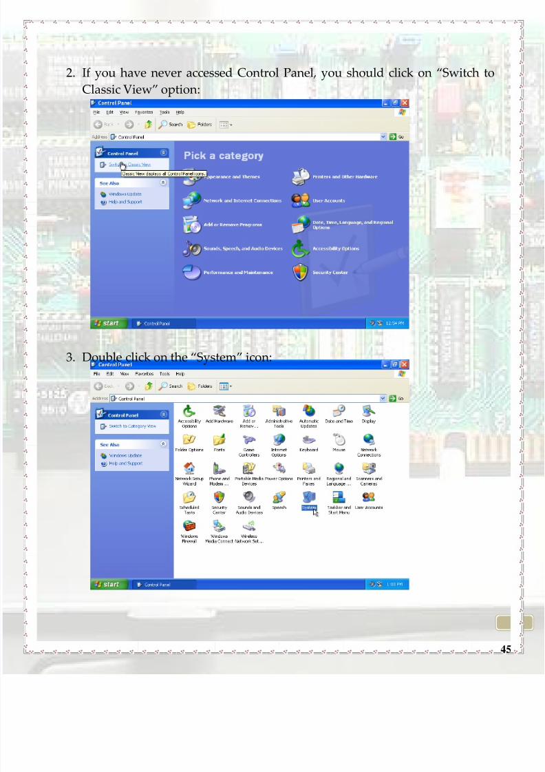
2. If you have never accessed Control Panel, you should click on ‚Switch to
Classic View‛ option:
3. Double click on the ‚System‛ icon:
8/8/2019 How to Network Brochure - Leonardo 2010
http://slidepdf.com/reader/full/how-to-network-brochure-leonardo-2010 46/74
46
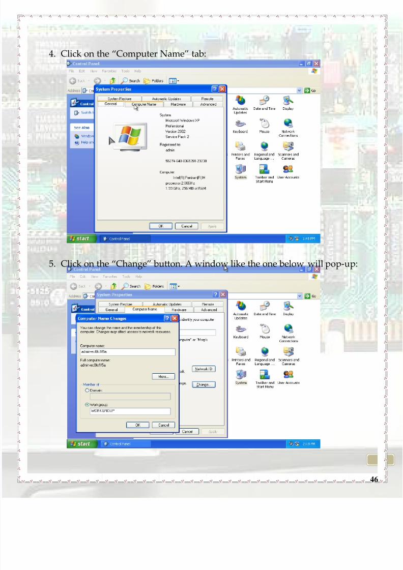
4. Click on the ‚Computer Name‛ tab:
5. Click on the ‚Change‛ button. A window like the one below will pop-up:

8/8/2019 How to Network Brochure - Leonardo 2010
http://slidepdf.com/reader/full/how-to-network-brochure-leonardo-2010 47/74
47
You can change the workgroup name by editing the workgroup field.
When you are done, click on the ‚OK‛ button. You will be asked to restart your
system in order for the changes to take effect.
The next step is to set the computer IP addresses. Probably you’re now
wondering what the IP addresses are. Well, there are unique numbers to identify
computers within a network. Imagine them as being telephone numbers of
computers. There are 2 types of IP addresses: public and private. Public IP
addresses are those assigned to the computers when connected to the Internet.
Private IP addresses are those in a home network, that are never used on the
Internet.

8/8/2019 How to Network Brochure - Leonardo 2010
http://slidepdf.com/reader/full/how-to-network-brochure-leonardo-2010 48/74
48
Therefore, the computers in your network must have private IP addresses
from the following ranges:
10.0.0.0 – 10.255.255.255
172.16.0.0 – 172.31.255.255
192.168.0.0 – 192.168.255.255
It is recommended to use the third range.
You can set the IP address of a specific computer in the network by
following the steps below:
1. Click the Start button and enter the Control Panel:

8/8/2019 How to Network Brochure - Leonardo 2010
http://slidepdf.com/reader/full/how-to-network-brochure-leonardo-2010 49/74
49
2. Click on the ‚Network Connections‛ icon:
3. Right click on the network connection you want to configure, and then
choose ‚Properties‛:

8/8/2019 How to Network Brochure - Leonardo 2010
http://slidepdf.com/reader/full/how-to-network-brochure-leonardo-2010 50/74
50
4. A window like below will pop up:
5. Now check the ‚Use the following IP addresses‛ radio box. The ‚Use the
following DNS server addresses‛ radio box will be checked automatically:
8/8/2019 How to Network Brochure - Leonardo 2010
http://slidepdf.com/reader/full/how-to-network-brochure-leonardo-2010 51/74
51
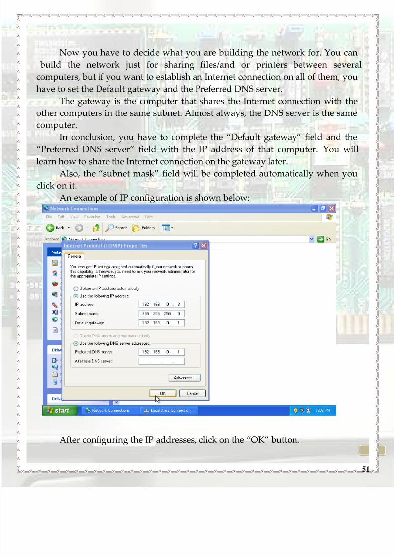
Now you have to decide what you are building the network for. You can
build the network just for sharing files/and or printers between several
computers, but if you want to establish an Internet connection on all of them, you
have to set the Default gateway and the Preferred DNS server.
The gateway is the computer that shares the Internet connection with the
other computers in the same subnet. Almost always, the DNS server is the same
computer.
In conclusion, you have to complete the ‚Default gateway‛ field and the
‚Preferred DNS server‛ field with the IP address of that computer. You will
learn how to share the Internet connection on the gateway later.
Also, the ‚subnet mask‛ field will be completed automatically when you
click on it.
An example of IP configuration is shown below:
After configuring the IP addresses, click on the ‚OK‛ button.

8/8/2019 How to Network Brochure - Leonardo 2010
http://slidepdf.com/reader/full/how-to-network-brochure-leonardo-2010 52/74
52
To share files in the network you’ve just created, follow the steps below:
1. After clicking on ‚My Computer‛, right click on the folder or partition that
you want to share, then choose ‚Properties‛:
2. A window like below should pop-up. Click on the ‚Sharing‛ tab, and then
click on ‚If you understand the risks, but you still want to share the root of
drive, click here‛:

8/8/2019 How to Network Brochure - Leonardo 2010
http://slidepdf.com/reader/full/how-to-network-brochure-leonardo-2010 53/74
53
3. Check the ‚Share this folder on the network‛ option. If you are on a
network where you trust all the persons having access to it (ex. at home)
and you want to allow the network user to change your files (edit them,
move them, delete them,...), then check the ‚Allow network user to change
my files‛ option:
Your shared folder / drive should now be accessible through ‚My network
places‛ on all computers within your network:
8/8/2019 How to Network Brochure - Leonardo 2010
http://slidepdf.com/reader/full/how-to-network-brochure-leonardo-2010 54/74
54
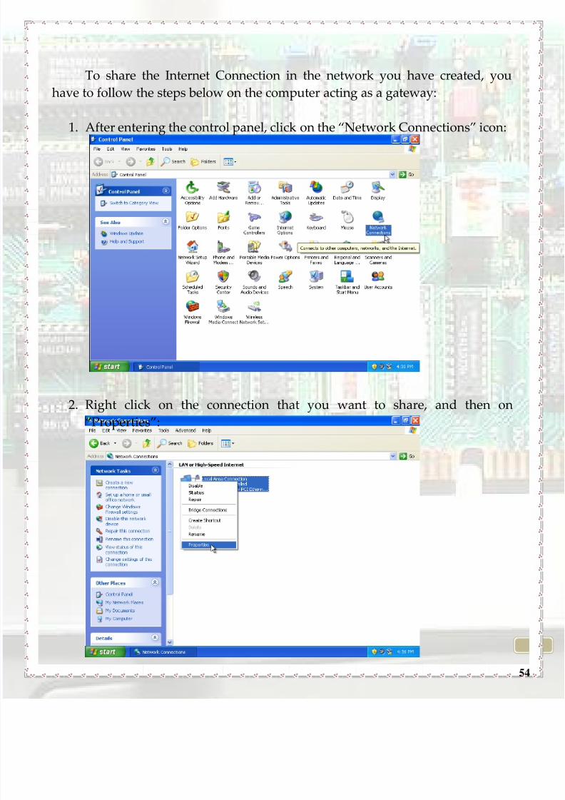
To share the Internet Connection in the network you have created, you
have to follow the steps below on the computer acting as a gateway:
1. After entering the control panel, click on the ‚Network Connections‛ icon:
2. Right click on the connection that you want to share, and then on
‚Properties‛:
8/8/2019 How to Network Brochure - Leonardo 2010
http://slidepdf.com/reader/full/how-to-network-brochure-leonardo-2010 55/74
55
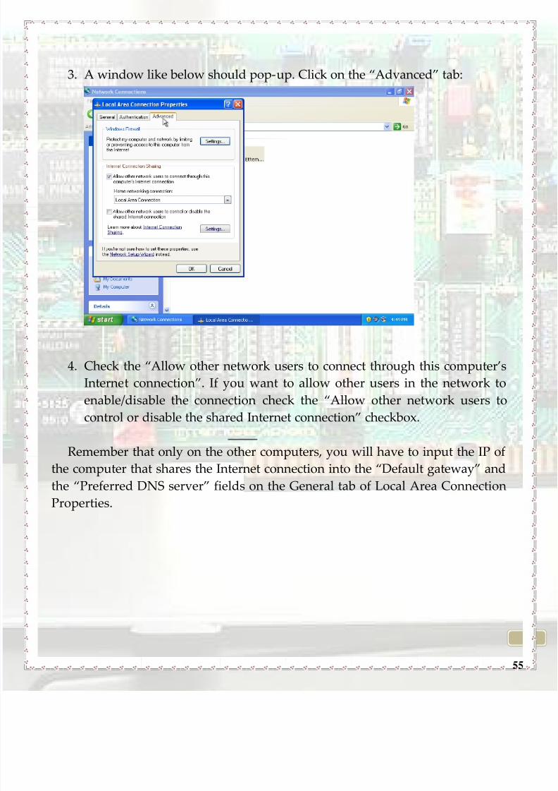
3. A window like below should pop-up. Click on the ‚Advanced‛ tab:
4. Check the ‚Allow other network users to connect through this computer’s
Internet connection‛. If you want to allow other users in the network to
enable/disable the connection check the ‚Allow other network users to
control or disable the shared Internet connection‛ checkbox.
Remember that only on the other computers, you will have to input the IP of
the computer that shares the Internet connection into the ‚Default gateway‛ and
the ‚Preferred DNS server‛ fields on the General tab of Local Area Connection
Properties.

8/8/2019 How to Network Brochure - Leonardo 2010
http://slidepdf.com/reader/full/how-to-network-brochure-leonardo-2010 56/74
56
Now you will learn how to connect a computer with GNU/Linux installed
to a TCP/IP network.
After installing GNU/Linux on a computer and assigning it the IP address,
you will need to give it a secondary IP address which should share the same
subnet with the main router if your network is part of a bigger LAN.
1. Go to ‚Applications‛ menu
2. Click ‚Accessories‛
3. Click ‚Terminal‛
4. Type "ifconfig eth0:0 (IP)", where ‚(IP)‛ is the IP address which you
assigned to the computer.
To set the gateway type: "route add default gw (IP of gateway)"
You need to mask the PCs behind your gateway in order to gain access to the
Internet. Turn on NAT (Network Address Translation) and masquerading on bytyping: "iptables -t nat -A POSTROUTING -o eth0 -j MASQUERADE"
*Tip: If your subnet's gateway has Linux OS installed you need to type the
following commands every time you turn it on in order to connect to the
internet:
1. "ech0 1 >/proc/sys/net/ipv4/ip_forward" - turns it into a router for the other PCs in
your subnet
2. "ifconfig eth0:0 (IP)"3. "route add default gw (IP of the central gateway)"
**You can check your configuration with the command ‚ifconfig‛.

8/8/2019 How to Network Brochure - Leonardo 2010
http://slidepdf.com/reader/full/how-to-network-brochure-leonardo-2010 57/74
57
APPENDIX I: TECHNICAL TERMS AND
EXPLANATIONS

8/8/2019 How to Network Brochure - Leonardo 2010
http://slidepdf.com/reader/full/how-to-network-brochure-leonardo-2010 58/74
58
COAXIAL CABLE
Coaxial cable is the kind of copper cable
used by cable TV companies between the
community antenna and user homes and
businesses. Coaxial cable is sometimes used by
telephone companies from their central office to
the telephone poles near users. It is also widely
installed for use in business and corporation Ethernet and other types of local
area network. Coaxial cable is called "coaxial" because it includes one physical
channel that carries the signal surrounded by another concentric physical
channel, both running along the same axis. The outer channel serves as a ground.
Many of these cables or pairs of coaxial tubes can be placed in a single outersheathing and, with repeaters, can carry information for a great distance.
TWISTED PAIR CABLE
Twisted pair is the type of cable that consists of two independently wires
(the forward and return conductors of a single circuit) twisted around one
another.
CONVERTERA converter is a device that helps us to interconnect different types of
cables by converting data from one cable to another.
HUB
In general, a hub is the central part of a wheel where the spokes come
together. In data communications, a hub is the central connection for all the
computers in a network, usually Ethernet-based. So this hardware device is a
place of convergence and when a piece of information arrives at one of itsports, it is copied and sent to the other ports, so that all the segments of the Local
Area Network can see it.
8/8/2019 How to Network Brochure - Leonardo 2010
http://slidepdf.com/reader/full/how-to-network-brochure-leonardo-2010 59/74
59
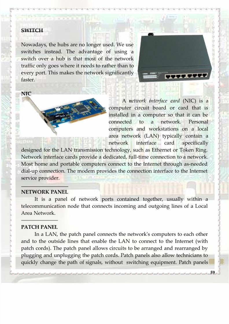
SWITCH
Nowadays, the hubs are no longer used. We use
switches instead. The advantage of using a
switch over a hub is that most of the network
traffic only goes where it needs to rather than to
every port. This makes the network significantly
faster.
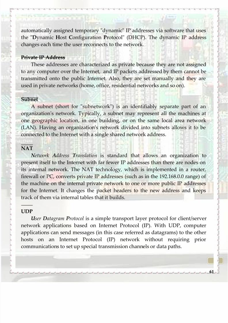
NIC
A network interface card (NIC) is a
computer circuit board or card that is
installed in a computer so that it can beconnected to a network. Personal
computers and workstations on a local
area network (LAN) typically contain a
network interface card specifically
designed for the LAN transmission technology, such as Ethernet or Token Ring.
Network interface cards provide a dedicated, full-time connection to a network.
Most home and portable computers connect to the Internet through as-needed
dial-up connection. The modem provides the connection interface to the Internetservice provider.
NETWORK PANEL
It is a panel of network ports contained together, usually within a
telecommunication node that connects incoming and outgoing lines of a Local
Area Network.
PATCH PANELIn a LAN, the patch panel connects the network's computers to each other
and to the outside lines that enable the LAN to connect to the Internet (with
patch cords). The patch panel allows circuits to be arranged and rearranged by
plugging and unplugging the patch cords. Patch panels also allow technicians to
quickly change the path of signals, without switching equipment. Patch panels

8/8/2019 How to Network Brochure - Leonardo 2010
http://slidepdf.com/reader/full/how-to-network-brochure-leonardo-2010 60/74
60
was first used by early telephone exchanges but nowadays they are used to
connect different devices, such as microphones, electric or electronic instruments,
effects etc.
TCP
The Transmission Control Protocol (TCP) is one of the core protocols of the
Internet Protocol Suite. TCP is one of the two original components of the suite,
complementing the Internet Protocol (IP) and therefore the entire suite is
commonly referred to as TCP/IP.
A TCP connection provides the service of exchanging data directly between
two hosts reliably This means that a connection must be established and
announced - both sides must
acknowledge the state of the connection. If data packets are lost they are
retransmitted.TCP guarantees delivery of data and also guarantees that packets will be
delivered in the same order in which they were sent. Major Internet applications
rely on TCP: Mail, WWW, File Transfer.
The advantages: reliable connection, the applications using TCP don't
care about the state of the connection (not necessarily);
The disadvantage: protocol overhead.
IP ADDRESSAn Internet Protocol address (IP address) is a numerical label that is
assigned to devices participating in a computer network that uses the Internet
Protocol for communication between its nodes. The format of an IP address is a
32-bit numeric address written as four numbers separated by periods. Each
number can be zero to 255. For example, 89.38.207.120 could be an IP address.
The four numbers in an IP address are used in different ways to identify a
particular network and a host on that network.
Static and Dynamic IP
Network infrastructure devices such as servers, routers and firewalls are
typically assigned permanent "static" IP addresses. The client machines can also
be assigned static IPs by a network administrator, but most often are
8/8/2019 How to Network Brochure - Leonardo 2010
http://slidepdf.com/reader/full/how-to-network-brochure-leonardo-2010 61/74
61
automatically assigned temporary "dynamic" IP addresses via software that uses
the "Dynamic Host Configuration Protocol" (DHCP). The dynamic IP address
changes each time the user reconnects to the network.
Private IP AddressThese addresses are characterized as private because they are not assigned
to any computer over the Internet, and IP packets addressed by them cannot be
transmitted onto the public Internet. Also, they are set manually and they are
used in private networks (home, office, residential networks and so on).
Subnet
A subnet (short for "subnetwork") is an identifiably separate part of an
organization's network. Typically, a subnet may represent all the machines atone geographic location, in one building, or on the same local area network
(LAN). Having an organization's network divided into subnets allows it to be
connected to the Internet with a single shared network address.
NAT
N etwork Address T ranslation is standard that allows an organization to
present itself to the Internet with far fewer IP addresses than there are nodes on
its internal network. The NAT technology, which is implemented in a router,firewall or PC, converts private IP addresses (such as in the 192.168.0.0 range) of
the machine on the internal private network to one or more public IP addresses
for the Internet. It changes the packet headers to the new address and keeps
track of them via internal tables that it builds.
UDP
U ser Datagram Protocol is a simple transport layer protocol for client/server
network applications based on Internet Protocol (IP). With UDP, computerapplications can send messages (in this case referred as datagrams) to the other
hosts on an Internet Protocol (IP) network without requiring prior
communications to set up special transmission channels or data paths.

8/8/2019 How to Network Brochure - Leonardo 2010
http://slidepdf.com/reader/full/how-to-network-brochure-leonardo-2010 62/74
62
PROTOCOL
In computing and telecommunications, a protocol or communications
protocol is a formal description of message formats and the rules for exchanging
those messages. At the lowest level, a protocol defines the behaviour of a
hardware connection. Network engineers have written rules for communication
that must be strictly followed for successful communication between any 2 parts
involved.
Example: The protocols in human communication are separate rules about
appearance, speaking, listening and understanding. All these rules, also called
protocols of conversation, represent different layers of communication. They
work together to help people successfully communicate. The need for protocols
also applies to network devices.
OSI MODEL
The Open Systems Interconnection model (OSI model) is a product of the
Open Systems Interconnection effort at the International Organization for
Standardization. It is a way of sub-dividing a communications system into
smaller parts called layers. A layer is a collection of conceptually similar
functions that provide services to the layer above it and receives services from
the layer below it.
FRAME
In computer networking and telecommunication, a frame is a data packet
that includes frame synchronization. This is a sequence of bits or symbols
making it possible for the receiver to detect the beginning and end of the packet
in the stream of symbols or bits. If a receiver is connected to the system in the
middle of a frame transmission, it ignores the data until it detects a new frame
synchronization sequence.
ETHERNET
Ethernet is a family of frame-based computer networking technologies for
local area networks (LANs). It defines a number of wiring and signalling
8/8/2019 How to Network Brochure - Leonardo 2010
http://slidepdf.com/reader/full/how-to-network-brochure-leonardo-2010 63/74
63
standards for the Physical Layer of the OSI networking model as well as a
common addressing format. It is the most widespread wired LAN technology.
PORT
There are two types of computer ports: hardware ports and software ports.
A software port (usually just called a 'port') is a virtual/logical data
connection that can be used by programs to exchange data directly, instead of
going through a file or other temporary storage location.
A hardware port serves as an interface between the computer and other
computers or peripheral devices. Physically, a port is a specialized outlet on a
piece of equipment to which a plug or cable connects.
ServicesNetwork services are the foundation of a networked computing
environment. Generally network services are installed on one or more servers to
provide shared resources to client computers. Common network services
include:
• HTTP(S) – Websites and applications
• SMTP – eMail communication
• FTP – File Transfer Protocol
• DNS – Domain Name System• SSH – Secure Shell Access
• POP3(S) – Mailretrival protocol
• IMAP(S) – Mailbox protocol
HTTP
H yperText T ransfer Protocol , the standard way of transferring information
across the World Wide Web. HTTP defines how messages are formatted and
transmitted, and what actions Web servers and browsers should take inresponse to various commands. For example, when you enter a URL in your
browser, this actually sends an HTTP command to the Web server directing it to
fetch and transmit the requested Web page. HTTP is called a stateless protocol
because each command is executed independently, without any knowledge of

8/8/2019 How to Network Brochure - Leonardo 2010
http://slidepdf.com/reader/full/how-to-network-brochure-leonardo-2010 64/74
64
the commands that came before it. This is the main reason that it is difficult to
implement Web sites that react intelligently to user input.
SMTP
Simple M ail T ransfer Protocol, a protocol for sending e-mail messages
between servers. Most e-mail systems that send mail over the Internet use SMTP
to send messages from one server to another; the messages can then be retrieved
with an e-mail client using either POP or IMAP.
In addition, SMTP is generally used to send messages from a mail client to a
mail server. This is why you need to specify both the POP or IMAP server and
the SMTP server when you configure your e-mail application.
FTP F ile T ransfer Protocol is a standard network protocol used to copy a file
from one host to another over a TCP/IP-based network, such as the Internet.
DNS
The Domain N ame S ystem makes it possible to assign domain names to
groups of Internet users in a meaningful way, independent of each user's
physical location. Because of this, World Wide Web (WWW) hyperlinks and
Internet contact information can remain consistent and constant even if thecurrent Internet routing arrangements change or the participant uses a mobile
device. This is useful because Internet domain names are easier to remember
than IP addresses.
SSH
Secure Shell is a network protocol that allows data to be exchanged using a
secure channel between two networked devices. It is used primarily on Linux
and Unix based systems to access shell accounts. SSH was designed as areplacement for Telnet and other insecure remote shells, which send
information, notably passwords, in plaintext, rendering them susceptible to
packet analysis.

8/8/2019 How to Network Brochure - Leonardo 2010
http://slidepdf.com/reader/full/how-to-network-brochure-leonardo-2010 65/74
65
Routing
Routing represents, the process of moving a packet of data from source to
destination. Routing is usually performed by a dedicated device called a router.
Routing is a key feature of the Internet because it enables messages to pass from
one computer to another and eventually reach the target machine. Each
intermediary computer performs routing by passing along the message to the
next computer. Part of this process involves analyzing a routing table to
determine the best path.
ARPShort for Address Resolution Protocol, a network layer protocol used to
convert an IP address into a physical address (called a DLC address), such as an
Ethernet address.
The term address resolution refers to the process of finding an address of a
computer in a network. The address is "resolved" using a protocol in which a
piece of information is sent by a client process executing on the local computer
to a server process executing on a remote computer. The information received by
the server allows the server to uniquely identify the network system for whichthe address was required and therefore to provide the required address. The
address resolution procedure is completed when the client receives a response
from the server containing the required address.
MAU
M edium Attachment U nit , also known as "transceiver" converts signals on an
Ethernet cable to and from Attachment Unit Interface (AUI) signals.

8/8/2019 How to Network Brochure - Leonardo 2010
http://slidepdf.com/reader/full/how-to-network-brochure-leonardo-2010 66/74
66
APPENDIX II: THE OSI MODEL

8/8/2019 How to Network Brochure - Leonardo 2010
http://slidepdf.com/reader/full/how-to-network-brochure-leonardo-2010 67/74
67
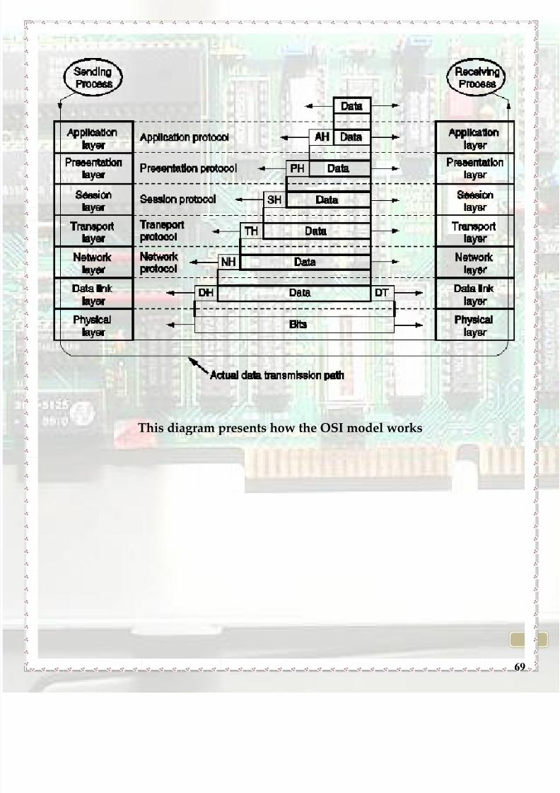
The OSI (O pen S ystems I nterconnection) reference model represents an
hierarchical communications structure used to constitute a network and to
allow communication between computers no matter what structural features
there are. As applications, OSI model divides network communication problem
of a hierarchical architecture composed of seven layers. Each layer has well
defined functions and communicates only with adjacent layers, allowing linking
different types of software and hardware.
Each level has well established positions and allows communication from
the top to bottom, in order to create well-established hierarchy.
Layer Role Protocols
7. Application - Serves as the window for users
and application
- Processes to access the network
service
Application / “End-user
visible”
HTTP, SMTP, FTP
6.
Presentation
- Formats the data to be presented by
the application Layer.
- It can be viewed as the ‚translator‚
for the network.
Session
SSL, TLS
5. Session - Allows session establishment
between processes Sockets / Streams
, Session establishment
- Running in different stations.
Transport
NetBIOS, L2TP, SIP
Allows session
establishment between
processes Sockets /
Streams , Session
establishment,
4.Transport - Ensures that data is delivered
error-free, in sequence and with no
losses or duplications
TCP/UDP
Message
acknowledgment
8/8/2019 How to Network Brochure - Leonardo 2010
http://slidepdf.com/reader/full/how-to-network-brochure-leonardo-2010 68/74
68
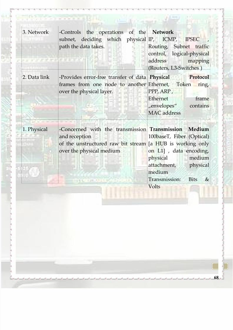
3. Network -Controls the operations of the
subnet, deciding which physical
path the data takes.
Network
IP, ICMP, IPSEC ,
Routing, Subnet traffic
control, logical-physical
address mapping
(Routers, L3-Switches )
2. Data link -Provides error-free transfer of data
frames from one node to another
over the physical layer.
Physical Protocol
Ethernet, Token ring,
PPP, ARP ,
Ethernet frame
„envelopes‚ contains
MAC address
1. Physical -Concerned with the transmission
and reception
of the unstructured raw bit stream
over the physical medium
Transmission Medium
100baseT, Fiber (Optical)
[a HUB is working only
on L1] , data encoding,
physical medium
attachment, physical
mediumTransmission: Bits &
Volts
8/8/2019 How to Network Brochure - Leonardo 2010
http://slidepdf.com/reader/full/how-to-network-brochure-leonardo-2010 69/74
69
This diagram presents how the OSI model works
8/8/2019 How to Network Brochure - Leonardo 2010
http://slidepdf.com/reader/full/how-to-network-brochure-leonardo-2010 70/74
70
APPENDIX III: BIBLIOGRAPHY
8/8/2019 How to Network Brochure - Leonardo 2010
http://slidepdf.com/reader/full/how-to-network-brochure-leonardo-2010 71/74
71
http://www.bukisa.com/articles/114814_network-topology-advantages-
and-disadvantages-of-star-and-mesh-topology
http://wiki.answers.com/Q/What_are_the_advantages_of_mesh_topology_
over_other_types_of_network_topology http://www.free-computer-tips.info/networking-tips/mesh-topology-tree-
topology-and-hybrid-topology.html
http://www.wikipedia.org
Bradley Mitchell "Network Topologies" [1], About.com Guide, retrieved
May 24 2010
http://www.ehow.com
http://www.youtube.com http://fcit.usf.edu/network/chap4/chap4.html
8/8/2019 How to Network Brochure - Leonardo 2010
http://slidepdf.com/reader/full/how-to-network-brochure-leonardo-2010 72/74
72
APPENDIX IV: EDITORIAL STAFF
8/8/2019 How to Network Brochure - Leonardo 2010
http://slidepdf.com/reader/full/how-to-network-brochure-leonardo-2010 73/74
73
COORDINATING TEACHER: Slobodan Aleksic
CHIEF EDITOR: Hodorog Andrei
EDITORIAL STAFF:Agavriloaei Matei-Andrei
Anghel TheodorAnton Mădălina Ioana
Bernevic Elsa-Maria
Bezrucav Ştefan Octavian
Borş Radu
Buhuş Corina-Mădălina
Chelsău Andreas-Mihael-Rareş
Chiţimuş Diana-Maria
Cojocaru Andreea-Roxana
Constantinescu AdelaDimitriu Ana-Maria-Andreea
Eşanu Tudor
Fâcă Ionuţ-Codrin
Filip Smaranda-Nicoleta
Flueraru Bogdan-Mihai
Foszto Monica
Fotache Mădălina-Ioana
Garas Radu
Humelnicu Roxana
Istrate Alexandra-BrendaIvan Monica
Merticariu Bogdan-Cristian
Mitu Ina-Maria
Munteanu Bogdan
Nechita Daniela-Elena
Petruşcă Monica
Pîrţac Adriana
Sava Lucian-Cristian
Siminiuc Iuliana-AntoanelaSiriteanu R. Lucian
Szabo P.T. Lavinia-Sabrina
Ştefan M.O. Ioana-Alexandra
Toma Florina
Veringă Gh. Iuliana-Andreea

8/8/2019 How to Network Brochure - Leonardo 2010
http://slidepdf.com/reader/full/how-to-network-brochure-leonardo-2010 74/74