
How-To Modbus-TCP communication between CelciuX and NJ
14
OEE-CH How-To Philipp Kontopulos Modbus-TCP communication between CelciuX and NJ HowTo_ModbusTCP_CelciuX_NJ.docx V1.2 Page 1 of 14 How-To Modbus-TCP communication between CelciuX and NJ History Date Version Author Description 03.10.12 1.0 pk 1 st release 04.10.12 1.1 pk Added very important notes (tips and tricks) 22.11.12 1.2 pk Minor corrections according Thomas Grootenboers
Transcript of How-To Modbus-TCP communication between CelciuX and NJ

OEE-CH How-To Philipp Kontopulos Modbus-TCP communication between CelciuX and NJ
HowTo_ModbusTCP_CelciuX_NJ.docx V1.2 Page 1 of 14
How-To
Modbus-TCP communication between CelciuX and NJ
History Date Version Author Description 03.10.12 1.0 pk 1st release 04.10.12 1.1 pk Added very important notes (tips and tricks) 22.11.12 1.2 pk Minor corrections according Thomas Grootenboers

OEE-CH How-To Philipp Kontopulos Modbus-TCP communication between CelciuX and NJ
HowTo_ModbusTCP_CelciuX_NJ.docx V1.2 Page 2 of 14
Table of contents 1 General ............................................................................................................................................................... 3
1.1 Validity ....................................................................................................................................................... 3
1.2 Motivation................................................................................................................................................... 3
2 CelciuX ............................................................................................................................................................... 4
2.1 Hardware requirements ............................................................................................................................. 4
2.1.1 Ethernet Module .................................................................................................................................... 4
2.1.2 End Unit ................................................................................................................................................. 4
2.1.3 Basic Unit ............................................................................................................................................... 4
2.2 Wiring ......................................................................................................................................................... 5
2.2.1 Power supply ......................................................................................................................................... 5
2.2.2 MX2 (Modbus RTU) ............................................................................................................................... 5
2.3 Setting up the system ................................................................................................................................ 6
2.3.1 MX2 parameters .................................................................................................................................... 6
2.3.2 Basic unit ............................................................................................................................................... 7
2.3.3 Ethernet Module .................................................................................................................................... 8
2.4 Read / Write to Modbus-RTU devices from NJ PLC ............................................................................... 10
2.4.1 Modbus functions (Function Codes) .................................................................................................... 10
2.4.2 Modbus-TCP Client for NJ ................................................................................................................... 11
2.4.3 Modbus registers for CelciuX modules ................................................................................................ 11
2.4.4 Modbus registers for MX2 .................................................................................................................... 11
A. EJ1N-HFU-ETN Modbus Address ............................................................................................................... 12

OEE-CH How-To Philipp Kontopulos Modbus-TCP communication between CelciuX and NJ
HowTo_ModbusTCP_CelciuX_NJ.docx V1.2 Page 3 of 14
1 General 1.1 Validity This document describes the Modbus-TCP communication between Omron Sysmac PLC NJ and the Omron CelciuX Ethernet gateway module.
1.2 Motivation Sysmac NJ offers an onboard standard multifunctional Ethernet interface. The lower onboard Ethernet port on Sysmac NJ offers real-time fieldbus EtherCAT. With the two interfaces any other fieldbus master on the PLC should be avoided as far as possible. The temperature controller CelciuX offers an interesting module (EJ1N-HFU-ETN) to communicate to host controllers via Ethernet. The module is supposed to communicate with PROFINET protocol but can also be used as a Modbus-TCP gateway without using PROFINET protocols at all. The CelciuX Ethernet-TCP gateway (EJ1N-HFU-ETN) can be used either with CelciuX temperature units or as a gateway for Modbus-RTU devices or even for both. EJ1N-HFU-ETN can also be used as PROFINET IO communication. Host controller then will be PNT21 for Omron PLCs. It also allows communication to CelciuX temperature units as well as to MX2-inverters or other Modbus-RTU devices. For detailed instructions please refer to www.myomron.com.

OEE-CH How-To Philipp Kontopulos Modbus-TCP communication between CelciuX and NJ
HowTo_ModbusTCP_CelciuX_NJ.docx V1.2 Page 4 of 14
2 CelciuX 2.1 Hardware requirements 2.1.1 Ethernet Module
An Ethernet module EJ1N-HFU-ETN is required for Ethernet communication. It must be placed at the very left side.
Please refer to 1661902-1A INSTRUCTION SHEET EJ1N-HFU-ETN.pdf for more details.
2.1.2 End Unit
An End Unit is required in any case. Either EJ1C-EDUA-NFLK (on board connectors) or EJ1C-EDUC-NFLK (removable screw connector blocks) can be used. The unit must be placed at the very right side. The End Unit is used for the following functions:
� Power supply DC 24V � Programming port for additional temperature control units � RS-485 interface (Modbus-RTU) for additional devices
2.1.3 Basic Unit
Basic units are temperature controllers. Choose either from EJ1N-TC2 or EJ1N-TC4 types. A variety of models are available.
� Please refer to datasheet “H144-E1-04.pdf” or “H145-E1-01.pdf” for more details

OEE-CH How-To Philipp Kontopulos Modbus-TCP communication between CelciuX and NJ
HowTo_ModbusTCP_CelciuX_NJ.docx V1.2 Page 5 of 14
2.2 Wiring 2.2.1 Power supply
DC 24V must be supplied to the End Unit. On EJ1C-EDUA-NFLK use pin 8 and 9.
On EJ1C-EDUC-NFLK use pin 9 and 10.
2.2.2 MX2 (Modbus RTU)
Connect MX2 to Port B of the End Unit. On EJ1C-EDUA-NFLK: Pin 6 / B(+) to terminal SP of MX2 Pin 7 / A(-) to terminal SN of MX2
On EJ1C-EDUC-NFLK: Pin 7 / B(+) to terminal SP of MX2 Pin 8 / A(-) to terminal SN of MX2

OEE-CH How-To Philipp Kontopulos Modbus-TCP communication between CelciuX and NJ
HowTo_ModbusTCP_CelciuX_NJ.docx V1.2 Page 6 of 14
Terminate the RS-485 wiring only on the last MX2 in the network. The built-in resistor can be activated by the dip switch.
� For further details please refer to “I570-E2-01-X+MX2+UsersManual.pdf”
2.3 Setting up the system 2.3.1 MX2 parameters
The MX2 inverter can be adjusted either with CX-Drive (USB communication) or manually with the keypad display or via Modbus-Master (as far as the Modbus communication is working). Please set the required parameters as follows: A001 Frequency Reference Selection 1 3: Modbus A002 RUN Command Selection 1 3: Modbus C071 Communication Speed Selection 10: 115200 bps Restart power needed C072 Communication Station No. Selection between 1…247 Keypad display only C074 Communication Parity Selection 1: Even parity Restart power needed C075 Communication Stop Bit Selection 1: 1 Bit Restart power needed C076 Operation Selection on Communication Error 2: Ignoring errors C077 Communication Error Timeout Time 0.00 C078 Communication Wait Time 0 C102 Reset Selection 3: Resetting only trip
� Please also refer to CX-Drive file MX2_ModbusRTU_Node247_120531pk.sdd

OEE-CH How-To Philipp Kontopulos Modbus-TCP communication between CelciuX and NJ
HowTo_ModbusTCP_CelciuX_NJ.docx V1.2 Page 7 of 14
2.3.2 Basic unit
Set Temperature Controller parameters by connecting the computer's USB port and an EJ1.
2.3.2.1 Switches on Basic Unit
1) On SW1 select unit number between 1…F � Unit number must be unique in the system, means different from node address MX2 (Parameter C072) and
different from other Basic Units!
2) On SW2 set all pins to OFF!
3) Power on DC 24V
2.3.2.2 Communication
1) The USB-Serial conversion cable E58-CIFQ1 must be plugged in to the END UNIT (on very top plug)
2) Open CX-Thermo on PC and connect to EJ1N
3) Change following parameters on all connected basic units Port B Communication Protocol Modbus Port B Communication Baud Rate 115’200 Port B Communication Data Length 8 Port B Communication Stop Bits 1
� Please also refer to CX-Thermo file 120621pk.cth. In the example two TC (basic units) are used

OEE-CH How-To Philipp Kontopulos Modbus-TCP communication between CelciuX and NJ
HowTo_ModbusTCP_CelciuX_NJ.docx V1.2 Page 8 of 14
2.3.3 Ethernet Module
2.3.3.1 IP-address
Use the following steps to configure the IP-address of EJ1N-HFU-ETN:
1) Make Ethernet connection between your PC and EJ1N-HFU-ETN port 1, 2 or 3. The three ports act as a switch. It does not matter which port you connect to.
2) Open CX-ConfiguratorFDT
3) Drag and drop the CJ1W-PNT21 to “My network”
4) Double click on CJ1W-PNT21 to open the configuration window
5) Click “Configure” to select the available Network Devices for Scanning and choose the appropriate Ethernet Controller on your PC.
6) Click “Start Scan” and right click the EJ1N-HFU-ETN to set the IP-address.
� Do deselect “Temporary Setting” to make sure, the IP-address is still valid after rebooting
7) The EJ1N-HFU-ETN can now be reached at this IP-address. CX-ConfiguratorFDT can be closed.

OEE-CH How-To Philipp Kontopulos Modbus-TCP communication between CelciuX and NJ
HowTo_ModbusTCP_CelciuX_NJ.docx V1.2 Page 9 of 14
2.3.3.2 Set Modbus-RTU parameters
For the following steps, please use: � ModbusTCP_Client_CelciuX.smc for NJ � NS8_ModbusTCP_CelciuX_MX2_121003_pk.IPP for NS (Test mode possible)
Following registers in the gateway EJ1N-HFU-ETN have to be set using Sysmac NJ-Controller:
1) Connect to the Modbus-TCP client
2) Write Value 4 to register address 0200h. << RTU Baud Rate: 115’200 >>
� Node address of EJ1N-HFU-ETN is FFh.
Important Notes:
� Values will be written to the EEPROM. Means after restart, new value is still available. Therefore avoid cyclic writing registers in EJ1N-HFU-ETN to save lifetime of EEPROM.
� For all supported registers by EJ1N-HFU-ETN, please refer to Appendix A or to myomron.com

OEE-CH How-To Philipp Kontopulos Modbus-TCP communication between CelciuX and NJ
HowTo_ModbusTCP_CelciuX_NJ.docx V1.2 Page 10 of 14
2.4 Read / Write to Modbus-RTU devices from NJ PLC 2.4.1 Modbus functions (Function Codes)
When using EJ1N-HFU-ETN as Modbus gateway the following functions are supported:
� Extracted from User’s Manual “H142-E1-05+EJ1+UsersManual.pdf”.

OEE-CH How-To Philipp Kontopulos Modbus-TCP communication between CelciuX and NJ
HowTo_ModbusTCP_CelciuX_NJ.docx V1.2 Page 11 of 14
2.4.2 Modbus-TCP Client for NJ
The NJ PLC is able to handle Modbus-TCP protocols via the onboard Ethernet interface Port 1. Supported Modbus function codes of EJ1N-HFU-ETN are included in the NJ project “ModbusTCP_Client_CelciuX.smc” as function blocks. Please feel free to add or upgrade the NJ code if necessary.
2.4.3 Modbus registers for CelciuX modules
For reading and writing to EJ1N Basic Units, such as TC2 or TC4 modules please refer to the Appendix on User’s Manual “H142-E1-05+EJ1+UsersManual.pdf”. The Parameter List shows all Modbus addresses.
Important Notes:
� Values will be written to the EEPROM. Means after restart, new value is still available. Therefore avoid cyclic writing registers in EJ1N-HFU-ETN to save lifetime of EEPROM.
2.4.4 Modbus registers for MX2
For reading and writing to MX2 frequency inverter please refer to the Appendix B-4 on User’s Manual “I570-E2-01-X+MX2+UsersManual.pdf”. The ModBus Data Listing shows all Modbus addresses.
Important Notes:
� Values will NOT be written to the EEPROM. Means after restart, previous values will be available. To write values to EEPROM refer to chapter B-3-5 Store New Register Data (ENTER command) in the user manual.
� MX2 Register address value (transmitted on Modbus line) is 1 less than the Register Number. E.g. Register Number in the manual for frequency source is 0001h. When reading or writing to MX2 use Register address 0000h! The Register address can also be checked in CX-Drive and they are not shifted by 1. E.g. Frequency source address is 0000h.
� MX2 supports broadcast messages. This can be helpful for stopping, starting or resetting inverters at the same time. But be aware of other slaves than MX2 in the network! With node 0 all inverters are addressed simultaneously. With node address 250 to 254 blocks are addressed simultaneously. E.g. Node address 250 means: broadcast to slave address 01 to 09. For further details please refer to B-3-2 Message Configuration: Query in the user manual.
� EJ1N-HFU-ETN does not support Modbus function codes to read or write into coils. Fortunately the MX2 coils are mapped to the registers so coils can indirectly be accessed with supported function codes! E.g. Register address 1F00h shows coil number 0001h to 000Fh
OEE-CH How-To Philipp Kontopulos Modbus-TCP communication between CelciuX and NJ
HowTo_ModbusTCP_CelciuX_NJ.docx V1.2 Page 12 of 14
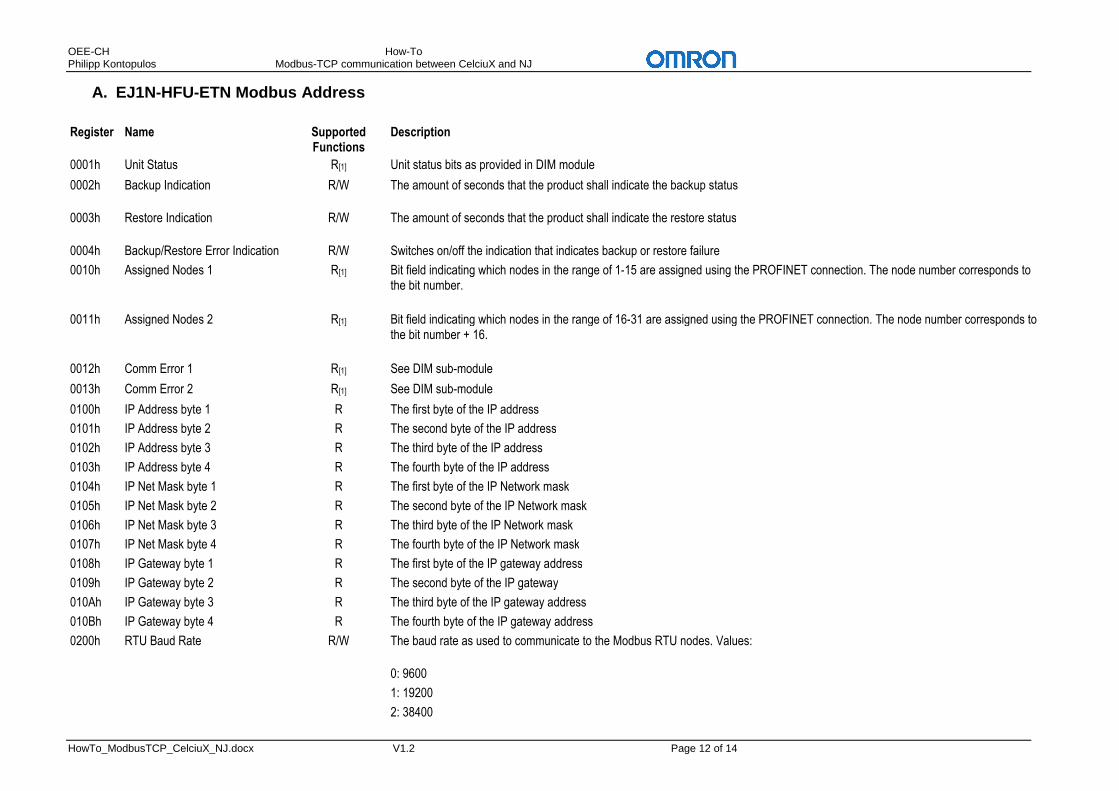
A. EJ1N-HFU-ETN Modbus Address Register Name Supported
Functions Description
0001h Unit Status R[1] Unit status bits as provided in DIM module
0002h Backup Indication R/W The amount of seconds that the product shall indicate the backup status
0003h Restore Indication R/W The amount of seconds that the product shall indicate the restore status
0004h Backup/Restore Error Indication R/W Switches on/off the indication that indicates backup or restore failure
0010h Assigned Nodes 1 R[1] Bit field indicating which nodes in the range of 1-15 are assigned using the PROFINET connection. The node number corresponds to the bit number.
0011h Assigned Nodes 2 R[1] Bit field indicating which nodes in the range of 16-31 are assigned using the PROFINET connection. The node number corresponds to the bit number + 16.
0012h Comm Error 1 R[1] See DIM sub-module
0013h Comm Error 2 R[1] See DIM sub-module
0100h IP Address byte 1 R The first byte of the IP address
0101h IP Address byte 2 R The second byte of the IP address
0102h IP Address byte 3 R The third byte of the IP address
0103h IP Address byte 4 R The fourth byte of the IP address
0104h IP Net Mask byte 1 R The first byte of the IP Network mask
0105h IP Net Mask byte 2 R The second byte of the IP Network mask
0106h IP Net Mask byte 3 R The third byte of the IP Network mask
0107h IP Net Mask byte 4 R The fourth byte of the IP Network mask
0108h IP Gateway byte 1 R The first byte of the IP gateway address
0109h IP Gateway byte 2 R The second byte of the IP gateway
010Ah IP Gateway byte 3 R The third byte of the IP gateway address
010Bh IP Gateway byte 4 R The fourth byte of the IP gateway address
0200h RTU Baud Rate R/W The baud rate as used to communicate to the Modbus RTU nodes. Values:
0: 9600
1: 19200
2: 38400

OEE-CH How-To Philipp Kontopulos Modbus-TCP communication between CelciuX and NJ
HowTo_ModbusTCP_CelciuX_NJ.docx V1.2 Page 13 of 14
3: not supported
4: 115200
0201h RTU Parity Setting R/W The parity setting as used to communicate to the Modbus RTU nodes. Values:
0: None
1: Even
2: Odd
0202h RTU Default Time-out R/W The default Modbus/RTU timeout
Range 100 - 25000 [ms]
1001h Node 1 Timeout R[1] The response time-out in 0.1s units for a Modbus request sent to Modbus RTU node 1
1002h Node 2 Timeout R[1] The response time-out in 0.1s units for a Modbus request sent to Modbus RTU node 2
... ... R[1] ...
101Fh Node 31 Timout R[1] The response time-out in 0.1s units for a Modbus request sent to Modbus RTU node 31
1021h Node 1 Func 17h R[1] The property of Modbus node 1 whether it supports Modbus function 17h
1022h Node 2 Func 17h R[1] The property of Modbus node 2 whether it supports Modbus function 17h
... ... R[1] ...
103Fh Node 31 Func 17h R[1] The property of Modbus node 31 whether it supports Modbus function 17h
1041h Node 1 Backup Total R[1] Amount of registers in the backup range for node 1
1042h Node 2 Backup Total R[1] Amount of registers in the backup range for node 2
... ... R[1] ...
105Fh Node 31 Backup Total R[1] Amount of registers in the backup range for node 31
1061h Node 1 Backup Start R[1] Backup range start address of node 1
1062h Node 2 Backup Start R[1] Backup range start address of node 2
... ... R[1] ...
107Fh Node 31 Backup Start R[1] Backup range start address of node 31
1081h Node 1 Retries R[1] Amount of retries for node 1 before reporting errors
1082h Node 2 Retries R[1] Amount of retries for node 2 before reporting errors
... ... R[1] ...
109Fh Node 31 Retries R[1] Amount of retries for node 31 before reporting errors

OEE-CH How-To Philipp Kontopulos Modbus-TCP communication between CelciuX and NJ
HowTo_ModbusTCP_CelciuX_NJ.docx V1.2 Page 14 of 14
1101h Node 1 Timeouts R[2] Number of time-outs detected for node 1
1102h Node 2 Timeouts R[2] Number of time-outs detected for node 2
... ... R[2] ...
111Fh Node 31 Timeouts R[2] Number of time-outs detected for node 31
1121h Node 1 Frame Errors R[2] Number of response frame errors detected for node 1
1122h Node 2 Frame Errors R[2] Number of response frame errors detected for node 2
... ... R[2] ...
113Fh Node 31 Frame Errors R[2] Number of response frame errors detected for node 31
1141h Node 1 Error Resps R[2] Number of error responses detected for node 1
1142h Node 2 Error Resps R[2] Number of error responses detected for node 2
... ... R[2] ...
115Fh Node 31 Error Resps R[2] Number of error responses detected for node 31
1161h Node 1 Requests OK R[2] Number of successfully completed Modbus requests for node 1
1162h Node 2 Requests OK R[2] Number of successfully completed Modbus requests for node 2
... ... R[2] ...
117Fh Node 31 Requests Ok R[2] Number of successfully completed Modbus requests for node 31
R = Read Only W = Write Only R/W = Read and Write Notes about [1] 1. Before a connection has been established with a PROFINET IO Controller the data is nonsensical. An illegal read or zero will be returned. Notes about [2] 1. The counters will be reset on each new PROFINET connect Notes about [3] 1. Reading the high word resets the counter 2. Reading the high word latches the low word so that the double word value can be read consistently Notes about [4] 1. Reading the high word latches the low word so that the double word value can be read consistently