How to connect Wing with Fuselage on a WWII Fighter Plane in SolidWorks
28
TUTORIAL BOOK #1 ADVANCED SURFACE MODELING SERIES WWW.SELCUKOZMUMCU.COM How to connect Wing with Fuselage on a WWII type fighterplane in SolidWorks.
-
Upload
selcuk-ozmumcu -
Category
Design
-
view
1.510 -
download
5
Transcript of How to connect Wing with Fuselage on a WWII Fighter Plane in SolidWorks

TUTORIAL BOOK #1ADVANCED SURFACE MODELING SERIES
W W W . S E L C U K O Z M U M C U . C O M
How to connect Wing with Fuselage on a WWII type fighterplane in SolidWorks.

It was 2005 or before, that I promised my self to make a 3D Model of Project Tiger. It is the freehand sketch whichhad ended up in 3D as seen in the background. This is how the Project Tiger story begins. You can see severalversions of it on my Concept Vehicles page.
As every surface modeler knows, it could be so tough at times to maintain curvature continuity. Learning andexperiencing it is another challenge, and it does not come easy for sure.
That is why the sole purpose of this tutorial, following and upcoming ones are to teach and guide you through some specific Advanced Surface Modeling situations and to give you some inspiration on your projects or to excellyour skills on Surface Modeling. I just want to share my humble opinion and knowledge on surface modeling tohelp people solve some specific occasions.
Intermediate or advanced level SolidWorks knowledge is necessary for this tutorial.
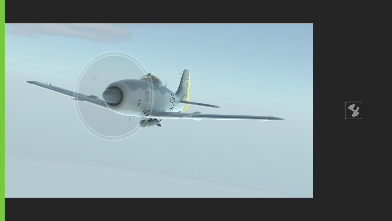
Second part of this book demonstrates some rendered images to show how your detailed, quality work pays off in the end. It always does!
Please feel free to contact me at [email protected].
Preface

Connection technique may vary depending on geometries we are dealing with. However, this type of fuselage design is commonly used in WWII fighter planes.
In this example, we start with a custom design WWII type fighter airplane which has a commonly used geometry of its fuselage.
I believe that this model could be useful for the ones related with aircraft modeling.

First, we decide where to cut (trim surface) on the fuselage and with which profile.
In this example, we start with a already cut fuselage which its cut borders are indicated with arrows.
Step 1

Because we cut with a sketch composed of several curves and lines, the cut border created on the fuselage does not have a continuededge along the border. So we need to create "combined curve" in order to use the whole edge as one continuous edge when connecting with other geometries.
The created combined curve is indicated with an arrow. We just used one half of the fuselage.
Step 2
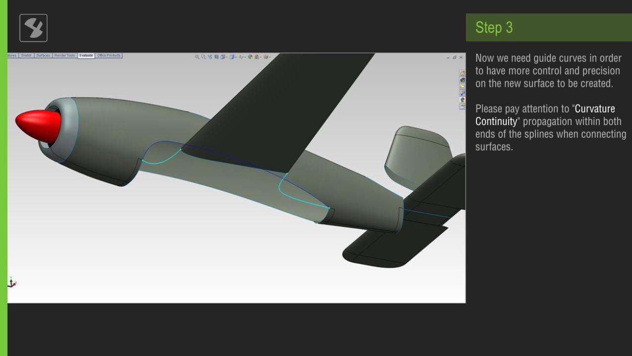
Now we need guide curves in order to have more control and precision on the new surface to be created.
Please pay attention to "Curvature Continuity" propagation within bothends of the splines when connecting surfaces.
Step 3

We use "Boundary Surface" tool in surface commands. You can see how all our guide curves, combined curve and the edge of the wing is used.
Step 4

It is time draw the bottom line curve in side view. This curve is veryimportant in our following steps.
Step 5

Please pay attention to "Curvature Continuity" propagation within end points of the spline with fuselage surfaces.
Step 6
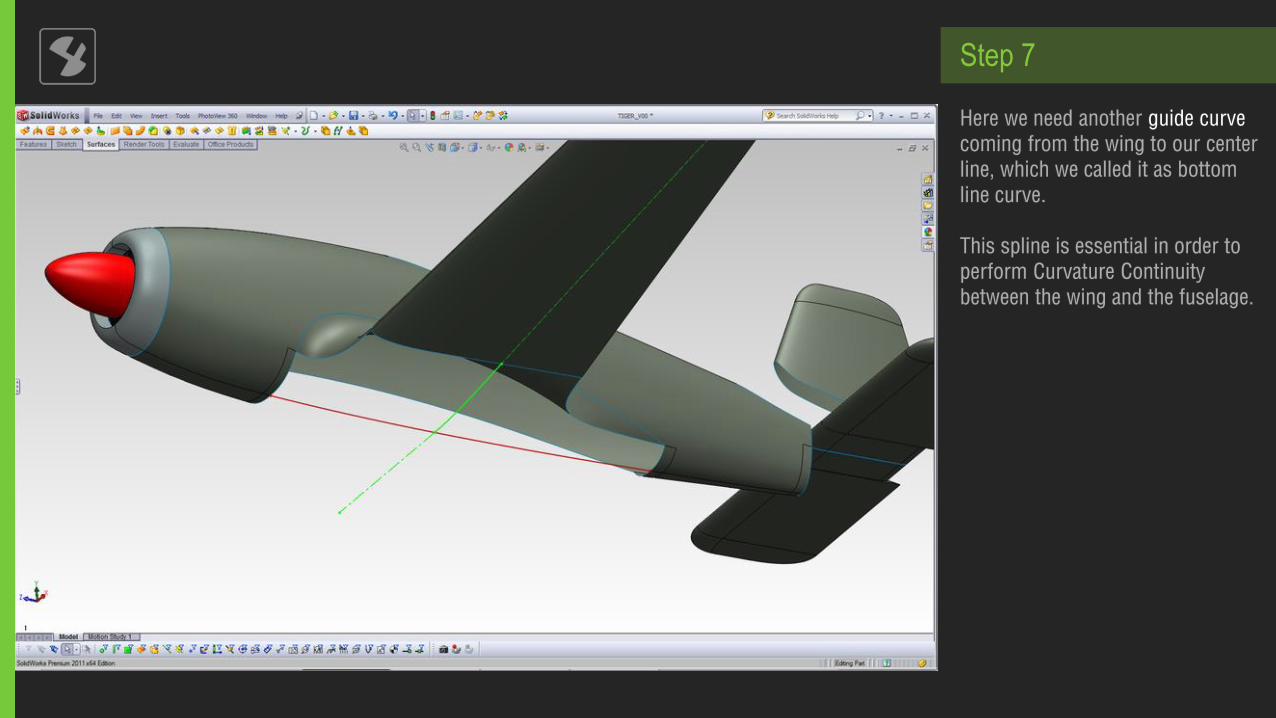
Here we need another guide curve coming from the wing to our center line, which we called it as bottom line curve.
This spline is essential in order to perform Curvature Continuity between the wing and the fuselage.
Step 7

We use Boundary Surface tool again as shown below.
Connection with the blue line stays as «Normal to Profile» and connection with the wing as seen as the blue surface at the top has to be «Curvature Continuity».
Step 8

Here is the result of the completed boundary surface.
Step 9

Now we need to trim this Boundary Surface! Why? We need to open a space for front and rear part of this boundary surface in order to be able to connect with the wing surface at the top.
Pay attention to trimming curves tonot to be tangent to the border edge in the bottom view. At the following step it will be much clear, which isshown with arrows.
Step 10

You can see the remaining areas left from the "Trim Surface" operation. These remaining areas are vital because we need a tangent/curvature continuity between the upcoming front and rear boundary surfaces with this bottom surface.
Step 11

Here comes the front surface! Again we use Boundary Surfacetool.
Step 12
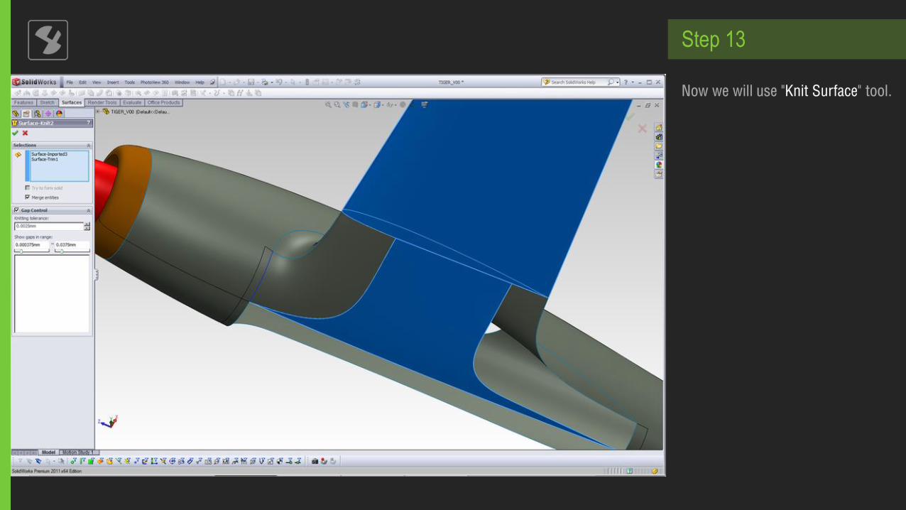
Now we will use "Knit Surface" tool.
Step 13

And comes the rear surface! Again we use boundary surface tool.
Step 14
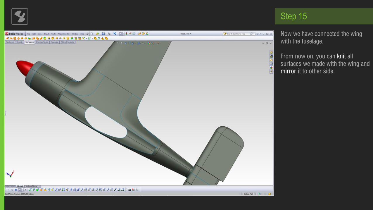
Now we have connected the wing with the fuselage.
From now on, you can knit all surfaces we made with the wing and mirror it to other side.
Step 15

Another view from upper part of the connecting surfaces.
Step 16

W W W . S E L C U K O Z M U M C U . C O M
RENDERS


W W W . S E L C U K O Z M U M C U . C O M