How to Conform to en 837-1 (summary)
18
How to conform to EN‐837‐1 (European Standard) Sizes and scale ranges: 1. Nominal sizes: 1.1 Industrial gauge: 40mm, 50mm, 63mm, 80mm, 100mm, 150mm, 160mm, 250mm General tolerances (EN 22768‐1):
-
Upload
matyas-kabai -
Category
Documents
-
view
223 -
download
1
Transcript of How to Conform to en 837-1 (summary)

8/18/2019 How to Conform to en 837-1 (summary)
http://slidepdf.com/reader/full/how-to-conform-to-en-837-1-summary 1/18
How to conform to EN‐837‐1 (European Standard)
Sizes and scale ranges:
1. Nominal sizes:
1.1 Industrial gauge: 40mm, 50mm, 63mm, 80mm, 100mm, 150mm,
160mm, 250mm
General tolerances (EN 22768‐1):
8/18/2019 How to Conform to en 837-1 (summary)
http://slidepdf.com/reader/full/how-to-conform-to-en-837-1-summary 2/18
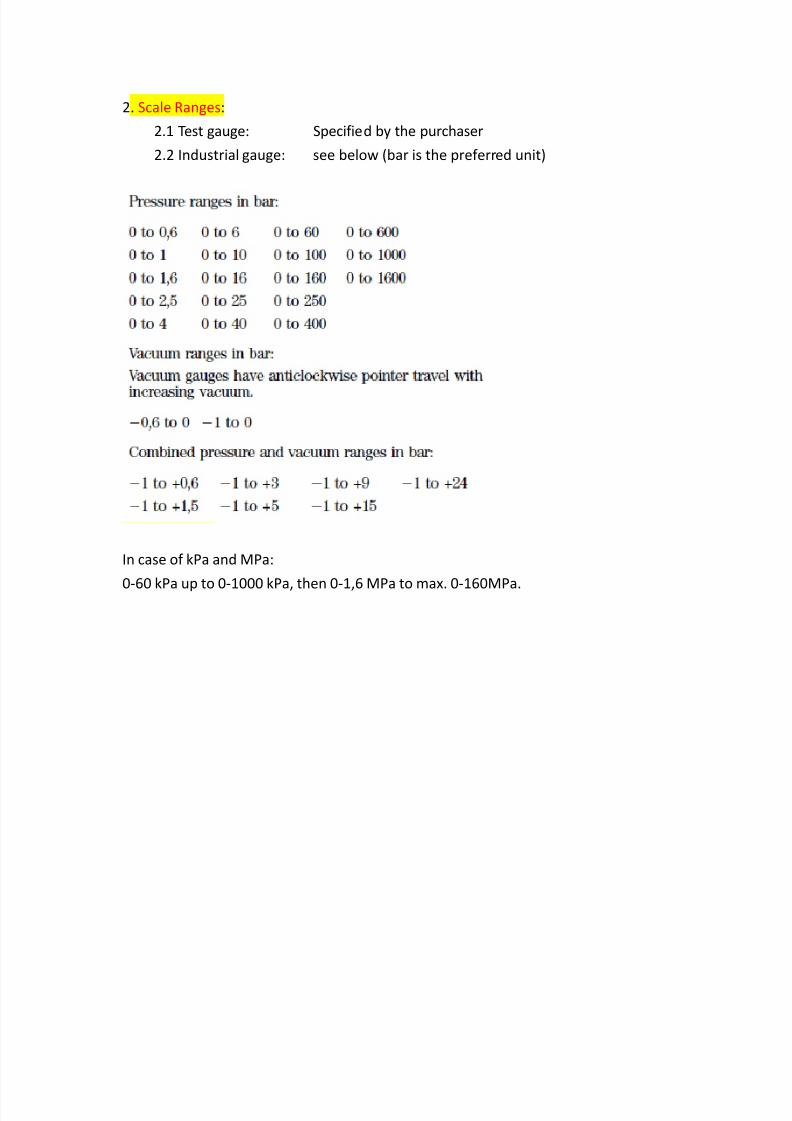
2. Scale Ranges:
2.1 Test gauge: Specified by the purchaser
2.2 Industrial gauge: see below (bar is the preferred unit)
In case of kPa and MPa:
0‐60 kPa up to 0‐1000 kPa, then 0‐1,6 MPa to max. 0‐160MPa.

8/18/2019 How to Conform to en 837-1 (summary)
http://slidepdf.com/reader/full/how-to-conform-to-en-837-1-summary 3/18
Design and construction:
0. General – Protection against corrosion – all parts that are not inherently resistant
to corrosion, must be painted or otherwise treated
1. Case design and construction
See Nominal sizes 1.1
2. Window designs
80mm and up gauges min. 3mm thick sheet of glass (or other
similar material specified by the purchaser)
Uniform in thickness and free from defects!
3. Mounting designs
3.1 Mounting of circular surface mounting gaugesSee Nominal sizes 1.1 (check enough space for the blowout device)
3.2 Mounting of circular flush mounting gauges
See Nominal sizes 1.1 (check enough space for the blowout device)
8/18/2019 How to Conform to en 837-1 (summary)
http://slidepdf.com/reader/full/how-to-conform-to-en-837-1-summary 4/18
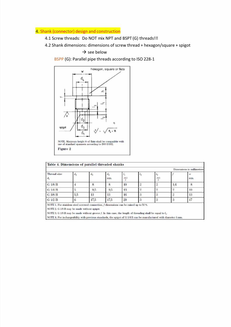
4. Shank (connector) design and construction
4.1 Screw threads: Do NOT mix NPT and BSPT (G) threads!!!
4.2 Shank dimensions: dimensions of screw thread + hexagon/square + spigot
see below
BSPP (G): Parallel pipe threads according to ISO 228‐1
8/18/2019 How to Conform to en 837-1 (summary)
http://slidepdf.com/reader/full/how-to-conform-to-en-837-1-summary 5/18
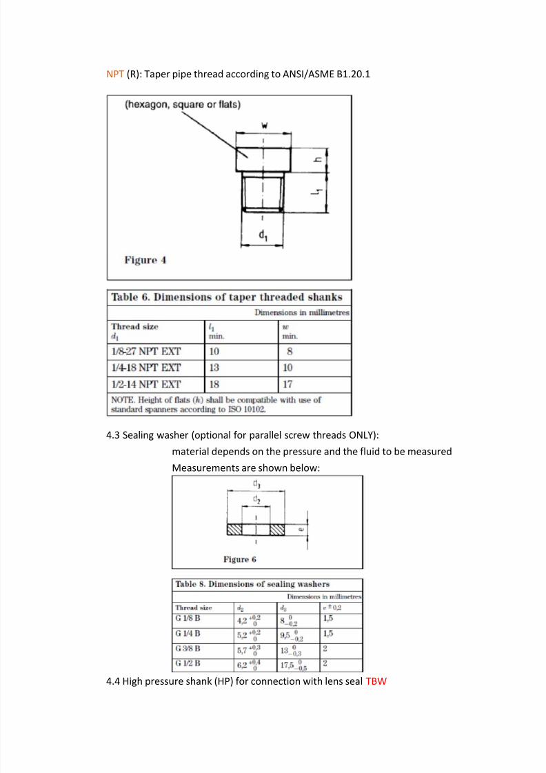
NPT (R): Taper pipe thread according to ANSI/ASME B1.20.1
4.3 Sealing washer (optional for parallel screw threads ONLY):
material depends on the pressure and the fluid to be measured
Measurements are shown below:
4.4 High pressure shank (HP) for connection with lens seal TBW
8/18/2019 How to Conform to en 837-1 (summary)
http://slidepdf.com/reader/full/how-to-conform-to-en-837-1-summary 6/18
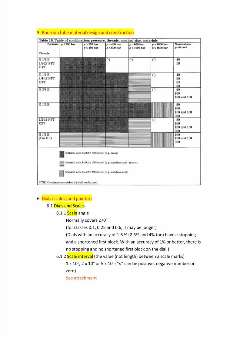
5. Bourdon tube material design and construction
6. Dials (scales) and pointers
6.1 Dials and Scales
6.1.1 Scale angle
Normally covers 270o
(for classes 0.1, 0.25 and 0.6, it may be longer)
(Dials with an accuracy of 1.6 % (2.5% and 4% too) have a stopping
and a shortened first block. With an accuracy of 1% or better, there is
no stopping and no shortened first block on the dial.)
6.1.2 Scale interval (the value (not length) between 2 scale marks)
1 x 10n, 2 x 10n or 5 x 10n (“n” can be positive, negative number or
zero)
See attachment

8/18/2019 How to Conform to en 837-1 (summary)
http://slidepdf.com/reader/full/how-to-conform-to-en-837-1-summary 7/18
6.1.3 Scale marks
Thickness of scale marks < 1/5 of scale spacing
Scale spacing > 1mm
Scale spacing constant (longest and shortest spacing
difference < 1/5)
(e.g. shortest 1mm longest < 1.2mm)
6.1.4 Scale numbering
Depends on manufacturer
See attachment
6.2 Pointers
6.2.1 Pointer dimensions
Tip of pointer width < minor scale mark width
Tip of pointer falls between 1/10 and 9/10 of shortest scale markMinimum pointer length from axis to tip is shown below:
6.3 Mirror scale
Class 0.1 gauge requires a mirror scale
Class 0.25 and 0.6 gauges must minimize parallax errors e.g.
use knife edge pointers optional, but recommended: use a mirror scale
6.4 Information on dial
a) unit of pressure
b) accuracy class at the end of scale
c) optional: type of pressure element symbol (see below)

8/18/2019 How to Conform to en 837-1 (summary)
http://slidepdf.com/reader/full/how-to-conform-to-en-837-1-summary 8/18
d) if gauge’s max. steady working pressure = max. scale value identifying
mark at max. scale value (see below)
e) if gauge is not calibrated for vertical use symbol of intended dial plane
angle
f) class 0.1, 0.25 and 0.6 gauges if a customer wants to use the gauge at
other than the reference temperature mark is needed
g) class 0.1, 0.25 and 0.6 gauges if the provided accuracy value of a
gauge is only for liquid or gas mark is needed
h) optional: indicate EN‐837‐1
j) name or logo of manufacturer/supplier
k) serial number class 0.1 and 0.25 (+ metrological‐related) mark
is needed
class 0.6 to 4 mark may be provided
m) if wetted parts differ from brass, bronze, tin, or hard solder mark is
needed
n) Safety pattern gauges mark is needed (see x.x.x)
o) Oxygen and acetylene gauges mark is needed (see x.x.x)

8/18/2019 How to Conform to en 837-1 (summary)
http://slidepdf.com/reader/full/how-to-conform-to-en-837-1-summary 9/18
6.5 Pointer stop
Max. steady working pressure = max. scale value free zero
Max. steady working pressure = 75% of max. scale value may have
free zero
7. Safety design See also: Test section
In case of pressure element failure in a safety gauge, blast and debris cannot
leave the gauge from the front. Recommendations as seen below:
7.1 Blow‐out device (S1) on gauges (no special marking is needed)
Requirements
a) resistant to blocking by debris and dirtb) pressure needed to function < half of window burst
pressure
c) installed on liquid filled gauges
7.2 Safety pattern gauges
Types a) 40‐80 size without baffle wall (S2)
b) 40‐250 size with baffle wall (S3)
7.2.1 Energy release test See Test section
7.2.2 Window
Non‐splintering material (e.g. laminated glass, or non‐splintering
plastic)
7.2.3 Blow‐out back
See 2.2.1
Also see Test section
7.2.4 Baffle wall
Permanent wall between Bourdon tube and dial.
Holes on wall cannot exceed 5% of overall area.
7.2.5 Marking (of safety pattern gauges)

8/18/2019 How to Conform to en 837-1 (summary)
http://slidepdf.com/reader/full/how-to-conform-to-en-837-1-summary 10/18
40‐80 size without baffle wall “S” mark and EN 837‐1 on dial
40‐250 size with baffle wall “S” mark and EN 837‐1 on dial
7.3 Oxygen or acetylene gauges
Must be safety pattern type gauge
Material must comply with EN 29539
7.3.1 Oxygen gauges
Wetted parts must be oil and grease free.
On dial “oxygen” and no lubrication symbol “ ”
7.3.2 Acetylene gauges
On dial “acetylene”
7.4 Liquid filled gauges
Atmospheric pressure compensator device (e.g. pressure relief vent)must be installed on the gauge
7.5 Metrology gauges TBW

8/18/2019 How to Conform to en 837-1 (summary)
http://slidepdf.com/reader/full/how-to-conform-to-en-837-1-summary 11/18
Accuracy, overload and temperature effects
1. Accuracy and overload
1.1 Accuracy classes
At 20C permissible errors are as follows:
1.1.1 Temperature effects: ± 0,04 x (t2 ‐ t1) %, where:
t1 = reference temperature in oC (about 20oC)
t2 = ambient temperature in oC (actual temperature)
1.2 Accuracy classes and nominal sizes
Gauges with pointer stop 10%‐100% range must be accurate
Gauges with free zero
0%‐100% range must be accurate
1.3 Endurance tests
1.3.1 Maximum steady working pressure 75% of the maximum scale
1.3.1.1 Steady pressure test
Maximum scale value for an extended period of time
1.3.1.2 Overpressure test
See below:

8/18/2019 How to Conform to en 837-1 (summary)
http://slidepdf.com/reader/full/how-to-conform-to-en-837-1-summary 12/18
1.3.1.3 Cyclic pressure test
Withstands pressure fluctuation from 30% to 60% of maximum
scale value for the following number of pressure cycles:
1.3.2 Maximum steady working pressure maximum scale (see 1.4.4/d)
1.3.1.1 Steady pressure and overpressure tests
1.3x the maximum scale value for an extended period of
time
1.3.1.2 Cyclic pressure test
Withstands pressure fluctuation from 30% to 95% of maximumscale value for 200,000 cycles (for classes 0.1, 0.25, and 0.6
15,000 is enough)
1.4 Operating conditions
1.4.1 Service temperature
Ambient: ‐20C to +60C
Fluid: based on the properties of the liquid
1.4.2 Storage temperature
‐40C to +70C (gauge cannot change its appearance (neither the dial))
1.4.3 Water and dust resistance
Minimum: IP31 (indoor) (Tools, thick wires, etc. / Dripping water )
IP44 (outdoor) (Most wires, slender screws, ants etc. /
Water splashing against the enclosure from any direction)
1.4.4 Mechanical shock
Shock loads of 150 m/s2 (for accuracy classes 1‐4)
1.4.5 Mechanical vibration
(for accuracy classes 1‐4)
8/18/2019 How to Conform to en 837-1 (summary)
http://slidepdf.com/reader/full/how-to-conform-to-en-837-1-summary 13/18
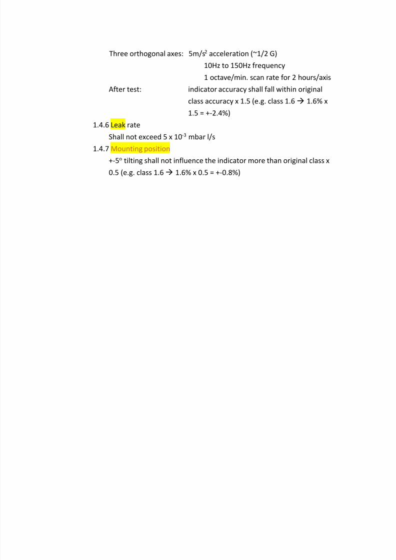
Three orthogonal axes: 5m/s2 acceleration (~1/2 G)
10Hz to 150Hz frequency
1 octave/min. scan rate for 2 hours/axis
After test: indicator accuracy shall fall within original
class accuracy x 1.5 (e.g. class 1.6 1.6% x
1.5 = +‐2.4%)
1.4.6 Leak rate
Shall not exceed 5 x 10‐3 mbar l/s
1.4.7 Mounting position
+‐5o tilting shall not influence the indicator more than original class x
0.5 (e.g. class 1.6 1.6% x 0.5 = +‐0.8%)
8/18/2019 How to Conform to en 837-1 (summary)
http://slidepdf.com/reader/full/how-to-conform-to-en-837-1-summary 14/18
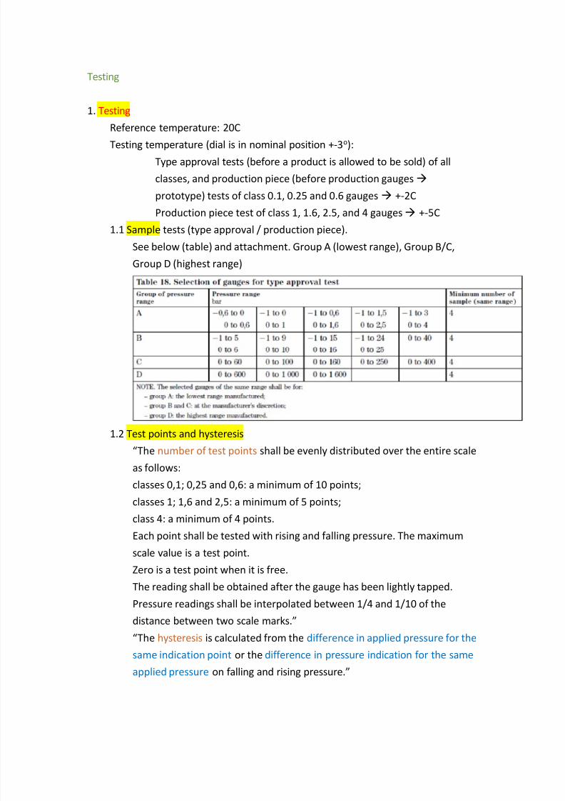
Testing
1. Testing
Reference temperature: 20C
Testing temperature (dial is in nominal position +‐3o):
Type approval tests (before a product is allowed to be sold) of all
classes, and production piece (before production gauges
prototype) tests of class 0.1, 0.25 and 0.6 gauges +‐2C
Production piece test of class 1, 1.6, 2.5, and 4 gauges +‐5C
1.1 Sample tests (type approval / production piece).
See below (table) and attachment. Group A (lowest range), Group B/C,
Group D (highest range)
1.2 Test points and hysteresis
“The number of test points shall be evenly distributed over the entire scale
as follows:
classes 0,1; 0,25 and 0,6: a minimum of 10 points;
classes 1; 1,6 and 2,5: a minimum of 5 points;
class 4: a minimum of 4 points.
Each point shall be tested with rising and falling pressure. The maximum
scale value is a test point.
Zero is a test point when it is free.
The reading shall be obtained after the gauge has been lightly tapped.
Pressure readings shall be interpolated between 1/4 and 1/10 of the
distance between two scale marks.”
“The hysteresis is calculated from the difference in applied pressure for the
same indication point or the difference in pressure indication for the same
applied pressure on falling and rising pressure.”

8/18/2019 How to Conform to en 837-1 (summary)
http://slidepdf.com/reader/full/how-to-conform-to-en-837-1-summary 15/18
1.3 Temperature (difference) effect test
From reference 20C temp., in 20C steps, ambient maximum (‐20C) and
minimum (+60) shall be reached. After thermal equilibrium is reached,
tests shall be run (see 1.2).
1.4 Endurance test See also Point 2.2 of Section Accuracy, overload and other
design Requirements for reference
1.4.1 Maximum steady working pressure 75% of the maximum scale
1.4.1.1 Steady pressure
Max. scale value 12 hours
1.4.1.2 Over‐pressure
See below 15 minutes
1.4.1.3 Cyclic pressure
Sinusoidally fluctuating pressure between 30%+‐5% and 60%+
5% of maximum scale value at 20 – 60 cycles per minute for X(see table) cycles.
E.g.: 100 bar max. scale value 30bar+‐5bar to 60bar+‐5bar and
back to 30bar+‐5bar (1 cycle) 20‐60 cycles/minute, 50000x =
~41 hours
Above 1000bar, frequency can be reduced to 1 cycle/minute.
1.4.2 Maximum steady working pressure Maximum scale
1.4.2.1 Steady and over‐pressure
Max. scale value x 1.3 12 hours
1.4.2.2 Cyclic pressure
8/18/2019 How to Conform to en 837-1 (summary)
http://slidepdf.com/reader/full/how-to-conform-to-en-837-1-summary 16/18
Sinusoidally fluctuating pressure between 30%+‐5% and 95%+
5% of maximum scale value at 20 – 60 cycles per minute for X
cycles. X can be 200000 cycles, or 15000 cycles for classes 0.1;
0.25 and 0.6.
E.g.: 100 bar max. scale value 30bar+‐5bar to 60bar+‐5bar and
back to 30bar+‐5bar (1 cycle) 20‐60 cycles/minute, 50000x =
~41 hours
Above 1000bar, frequency can be reduced to 1 cycle/minute.
1.4.3 Accuracy test (after endurance test)
Let it rest for 1 hour.
Test it according to 1.2 error cannot exceed 1.2 x class (e.g. class 1=1% x 1.2 = 1.2%)
0‐1000bar and 0‐1600bar error cannot exceed 1.5 x class
1.5 Rated temperature test
Pressure element assembly 24 hours inside climatic chamber at max.
allowed temperature (‐20C and +60C)
Up to 1000bar 2.5 x max. scale value applied pressure
Above 1000bar 1.5 x max. scale value applied pressure
Then leak test at ambient temperature (see 1.8)1.6 Rated storage temperature test
Complete unpressurized gauge 24 hours inside climatic chamber at each
(2) temperature extreme (‐40C and +70C)
Then check appearance; after 1 hour at reference temp. check accuracy,
hysteresis (see 1.2); leakage (see 1.8)
1.7 Leak test
Pressure up to max. scale value
Up to 25bar (~363psi) max. scale value gas
Above 25bar max. scale value liquid
1.8 Ingress of water and foreign particles test (IPXX)
EN 60529
1.9 Mechanical shock test
TBW, EN 60068‐2‐27
1.10 Mechanical vibration test
TBW EN 60068‐2‐6
8/18/2019 How to Conform to en 837-1 (summary)
http://slidepdf.com/reader/full/how-to-conform-to-en-837-1-summary 17/18
1.11 Mounting position test
Mount the gauge in a 5o angle forwards, backwards, to the left and right to
its normal position accuracy and hysteresis test (see 1.2) error cannot
exceed 0.5 x class.
1.12 Safety test
1.12.1 Gauges with blow‐out device
1.12.1.1 Constructional requirements
Blow‐out device must be in place (inspection)
1.12.1.2 Blow‐out test
Note: Liquid filled gauges should be tested with and without
liquid
a) Seal any leakage points by low strength sealantb) Pressurize the gauge via its connection (Bourdon tube is
removed)
c) Increase pressure till blow‐out device drops out or opens up
(not more than 100kPa) window and other components
cannot be damaged in any way
d) Block the blow‐out device and measure pressure that damages
the window (burst pressure)
1.12.2 Safety pattern gauge1.12.2.1 Constructional requirements
Visual inspection. See section “Accuracy, overload and other
design requirements” 2.2.2.2 – 2.2.2.5
1.12.2.2 Energy release test
a) Gas is released into the case through gauge connection. Up to
and for 63mm gauges bore size: min. 5mm. Above 63mm
gauges bore size: min. 10mm
b) Gas shall be stored in a “storage volume”, pressurized.
c) Gas storage volume connected to a (high speed – full valve
opening within 50ms) valve that in turn is connected to the
gauge’s connector.
d) Valve (and other connected pipes etc.) flow cross section
>28mm2
e) Length of connecting piping etc. <65mm
a1) Liquid fillable gauges must be tested with and without liquid
b1) Air bubble on top correct size
8/18/2019 How to Conform to en 837-1 (summary)
http://slidepdf.com/reader/full/how-to-conform-to-en-837-1-summary 18/18
c1) Protect the operator
1.12.2.2.1 Gauges without baffle wall (S2)
Release gas into the case energy (pressure x volume)
contained by pressure element at max. scale value x 1.5
1.12.2.2.2 Gauges with baffle wall (S3)
a) Up to and for 1000 bar gauges Release gas into
the case energy (pressure x volume) contained by
pressure element at max. scale value x 2.5
b) Above 1000 bar gauges Release gas into
the case energy (pressure x volume) contained by
pressure element at max. scale value x 1.5
1.12.2.3 Evaluation
Test is successful if no particles, or fluid leaves the gaugefrom the front.


![[2003] 1 A.C. 837](https://static.fdocuments.in/doc/165x107/577d20b11a28ab4e1e938966/2003-1-ac-837.jpg)