How To Configure Some Advanced Features on your ADSL Router · If your ADSL connection is up, the...
40
C613-16041-00 REV B www.alliedtelesis.com AlliedWare TM OS How To | Introduction This How To Note describes how to configure some of the more advanced features on your AT-AR440S or AT-AR441S ADSL router. It assumes that you have already set up basic Internet access on the router, and are now aiming to add more facilities to the configuration. What information will you find in this How To Note? This How To Note provides information about: z Firewall and NAT z DHCP server z DNS relay z ISDN backup of the ADSL link z VPN with NAT-T z Troubleshooting—basic and advanced Configure Some Advanced Features on your ADSL Router
Transcript of How To Configure Some Advanced Features on your ADSL Router · If your ADSL connection is up, the...
AlliedWareTM OS
How To | Configure Some Advanced Features on your ADSL Router
IntroductionThis How To Note describes how to configure some of the more advanced features on your AT-AR440S or AT-AR441S ADSL router. It assumes that you have already set up basic Internet access on the router, and are now aiming to add more facilities to the configuration.
What information will you find in this How To Note?This How To Note provides information about:
Firewall and NAT
DHCP server
DNS relay
ISDN backup of the ADSL link
VPN with NAT-T
Troubleshooting—basic and advanced
C613-16041-00 REV B www.alliedtelesis.com
Introduction
Table of contentsIntroduction .............................................................................................................................................. 1
What information will you find in this How To Note? ............................................................ 1
Firewall interfaces and NAT .................................................................................................................. 3
Firewall allow rules .................................................................................................................................. 8
Confirming your configuration .................................................................................................... 11
DHCP server .......................................................................................................................................... 12
Viewing the current DHCP server configuration ................................................................... 12
Altering DHCP server configurations ....................................................................................... 13
DNS Relay Configuration .................................................................................................................... 15
Enabling DNS relay using the GUI ............................................................................................. 16
Re-saving the configuration .......................................................................................................... 16
Configuring an ISDN backup link for your main ADSL link ........................................................ 17
Introduction ..................................................................................................................................... 17
1. Using a PPP secondary link ..................................................................................................... 17
2. Creating a second PPP definition over ISDN ...................................................................... 18
Verifying your back-up link ........................................................................................................... 20
IPsec VPN with NAT-T ......................................................................................................................... 23
How to troubleshoot your ADSL connection ................................................................................ 25
Introduction ..................................................................................................................................... 25
Basic troubleshooting—initial checklist .................................................................................... 25
Advanced troubleshooting 1: check the ADSL layer ............................................................. 26
Advanced troubleshooting 2: check the ATM Layer .............................................................. 28
Advanced troubleshooting 3: check the PPP Link ................................................................. 30
Advanced troubleshooting 4: check the IP layer .................................................................... 34
Advanced troubleshooting 5: check the IP routes ................................................................. 35
Appendix A: Typical ADSL performance figures to expect ......................................................... 36
Speed ................................................................................................................................................. 36
Signal-to-noise ratio margin ......................................................................................................... 36
Appendix B: Checking if your PC is correctly configured ............................................................ 37
Page 2 | AlliedWare™ OS How To Note: ADSL Router Advanced Features
Firewall interfaces and NAT
Firewall interfaces and NAT
The PCs on your LAN use private IP addresses. Your ISP allocates, or you have statically defined, a single public address to your router. When your PCs access the Internet via your router, the router must substitute its public IP address into the data packets as it sends them out. This process is called Network Address Translation (NAT). You must enable NAT on your router in order to enable multiple PCs on your LAN to access the Internet.
Enabling thefirewall
Also, it is very important to enable the firewall on the router to protect your LAN from attack.
If you ticked ‘enable firewall’ in the ADSL Setup GUI page, you will already have a basic firewall and NAT configuration. You can view your current configuration either with the GUI Diagnostics Command Line, or with the GUI Configuration > Firewall options.
To view the current firewall configuration via the Diagnostics > Command Line, use the command:
show configuration dynamic=firewall
You will get output something like this:
#
# FIREWALL configuration
#
enable firewall
create firewall policy="guilan"
enable firewall policy="guilan" icmp_f=all
add firewall policy="guilan" int=vlan1 type=private
add firewall policy="guilan" int=ppp0 type=public
add firewall poli="guilan" nat=enhanced int=vlan1 gblin=ppp0
The configuration assigns the public and private interfaces to the firewall and defines the NATing relationships of those interfaces.
If required you can view and alter your firewall settings using the GUI. Now, let us look, step by step, at how to achieve this:
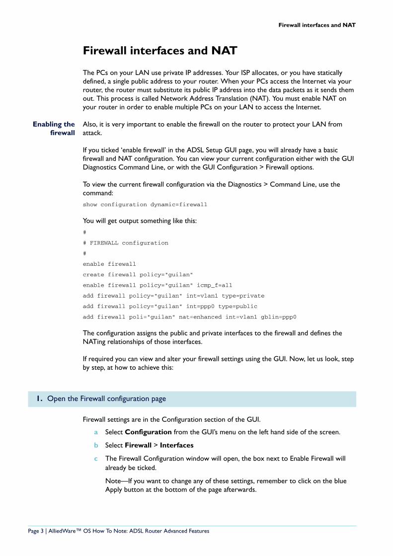
Firewall settings are in the Configuration section of the GUI.
a Select Configuration from the GUI’s menu on the left hand side of the screen.
b Select Firewall > Interfaces
c The Firewall Configuration window will open, the box next to Enable Firewall will already be ticked.
Note—If you want to change any of these settings, remember to click on the blue Apply button at the bottom of the page afterwards.
1. Open the Firewall configuration page
Page 3 | AlliedWare™ OS How To Note: ADSL Router Advanced Features
Firewall interfaces and NAT
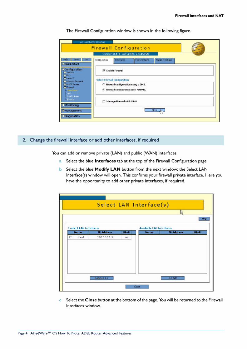
The Firewall Configuration window is shown in the following figure.
You can add or remove private (LAN) and public (WAN) interfaces.
a Select the blue Interfaces tab at the top of the Firewall Configuration page.
b Select the blue Modify LAN button from the next window; the Select LAN Interface(s) window will open. This confirms your firewall private interface. Here you have the opportunity to add other private interfaces, if required.
c Select the Close button at the bottom of the page. You will be returned to the Firewall Interfaces window.
2. Change the firewall interface or add other interfaces, if required
Page 4 | AlliedWare™ OS How To Note: ADSL Router Advanced Features
Firewall interfaces and NAT
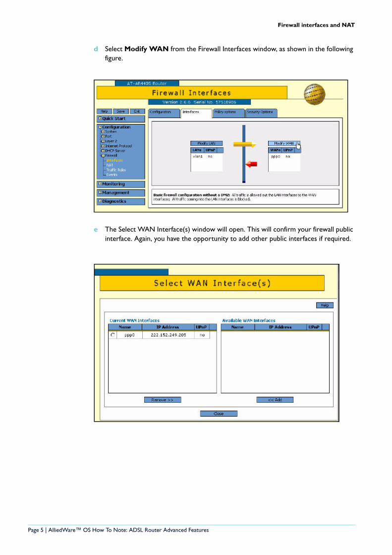
d Select Modify WAN from the Firewall Interfaces window, as shown in the following figure.
e The Select WAN Interface(s) window will open. This will confirm your firewall public interface. Again, you have the opportunity to add other public interfaces if required.
Page 5 | AlliedWare™ OS How To Note: ADSL Router Advanced Features
Firewall interfaces and NAT
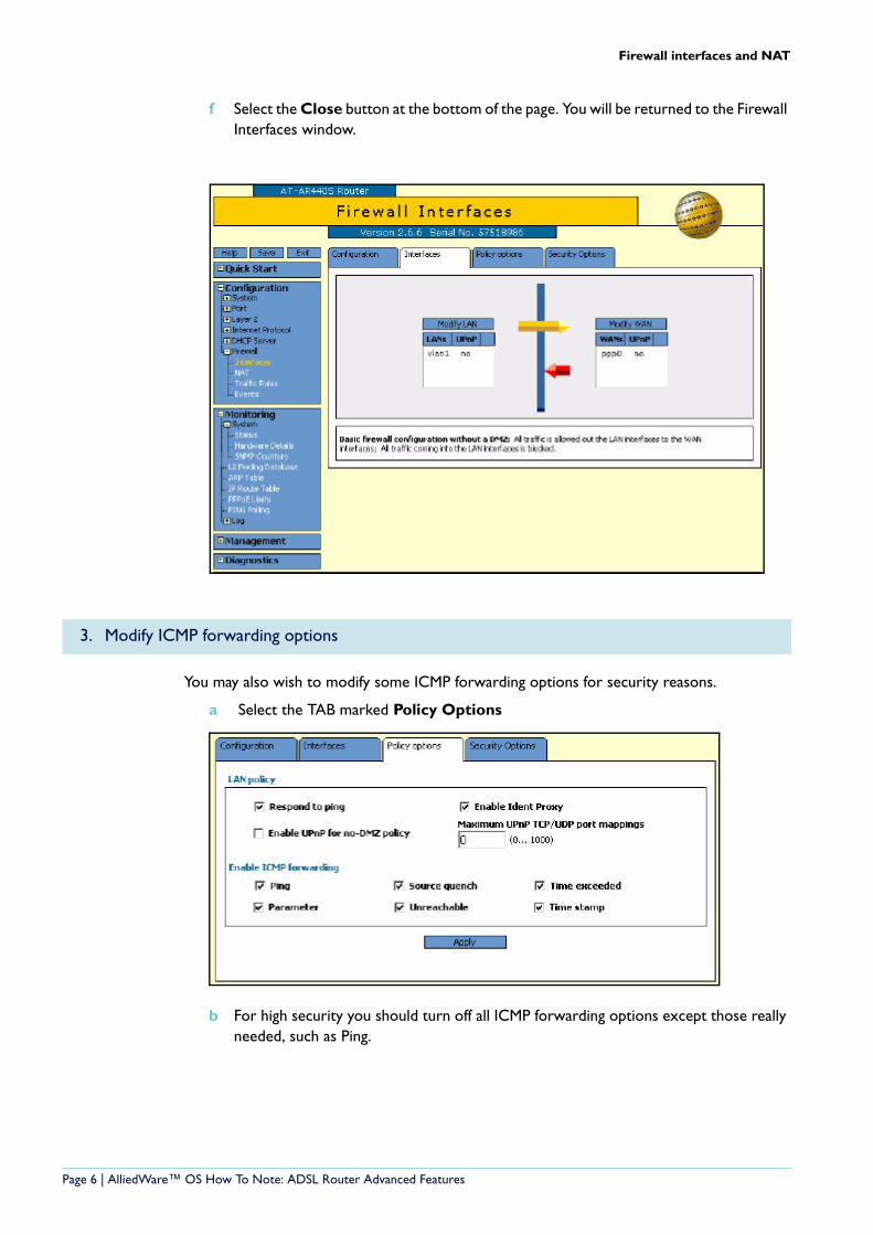
f Select the Close button at the bottom of the page. You will be returned to the Firewall Interfaces window.
You may also wish to modify some ICMP forwarding options for security reasons.
a Select the TAB marked Policy Options
b For high security you should turn off all ICMP forwarding options except those really needed, such as Ping.
3. Modify ICMP forwarding options
Page 6 | AlliedWare™ OS How To Note: ADSL Router Advanced Features
Firewall interfaces and NAT
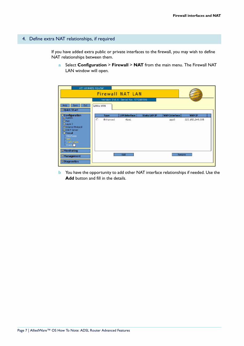
If you have added extra public or private interfaces to the firewall, you may wish to define NAT relationships between them.
a Select Configuration > Firewall > NAT from the main menu. The Firewall NAT LAN window will open.
b You have the opportunity to add other NAT interface relationships if needed. Use the Add button and fill in the details.
4. Define extra NAT relationships, if required
Page 7 | AlliedWare™ OS How To Note: ADSL Router Advanced Features
Firewall allow rules
Firewall allow rules
You may also need to define some allow rules or ‘pinholes’ to allow externally initiated traffic of some types. For example, you may have a Web server that you wish to allow the public to access. Please note that allowing access to servers will normally mean you need a fixed public address rather than dynamically assigned. If your address is dynamically assigned, you will need a dynamic DNS domain name arrangement.
If your ADSL connection is up, the configuration below will pick up the current WAN address to be the global IP address of your allow rule. If you need the global IP address to dynamically change to any current WAN address, then first disconnect your ADSL line while you configure, and the global IP parameter will take the desired value 0.0.0.0. This is effectively a ‘wild card’ value for the global IP, and has the effect that the rule will use whatever IP address happens to have been learnt on the WAN interface at any given time.
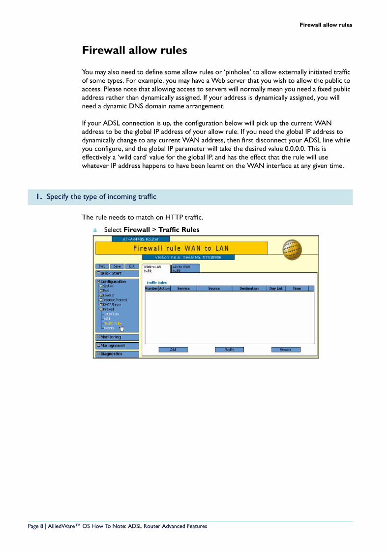
The rule needs to match on HTTP traffic.
a Select Firewall > Traffic Rules
1. Specify the type of incoming traffic
Page 8 | AlliedWare™ OS How To Note: ADSL Router Advanced Features
Firewall allow rules
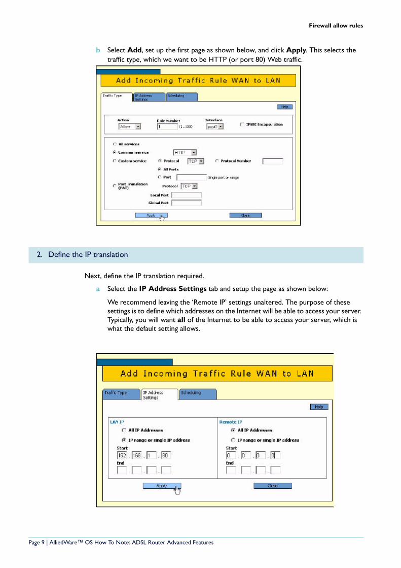
b Select Add, set up the first page as shown below, and click Apply. This selects the traffic type, which we want to be HTTP (or port 80) Web traffic.
Next, define the IP translation required.
a Select the IP Address Settings tab and setup the page as shown below:
We recommend leaving the ‘Remote IP’ settings unaltered. The purpose of these settings is to define which addresses on the Internet will be able to access your server. Typically, you will want all of the Internet to be able to access your server, which is what the default setting allows.
2. Define the IP translation
Page 9 | AlliedWare™ OS How To Note: ADSL Router Advanced Features
Firewall allow rules
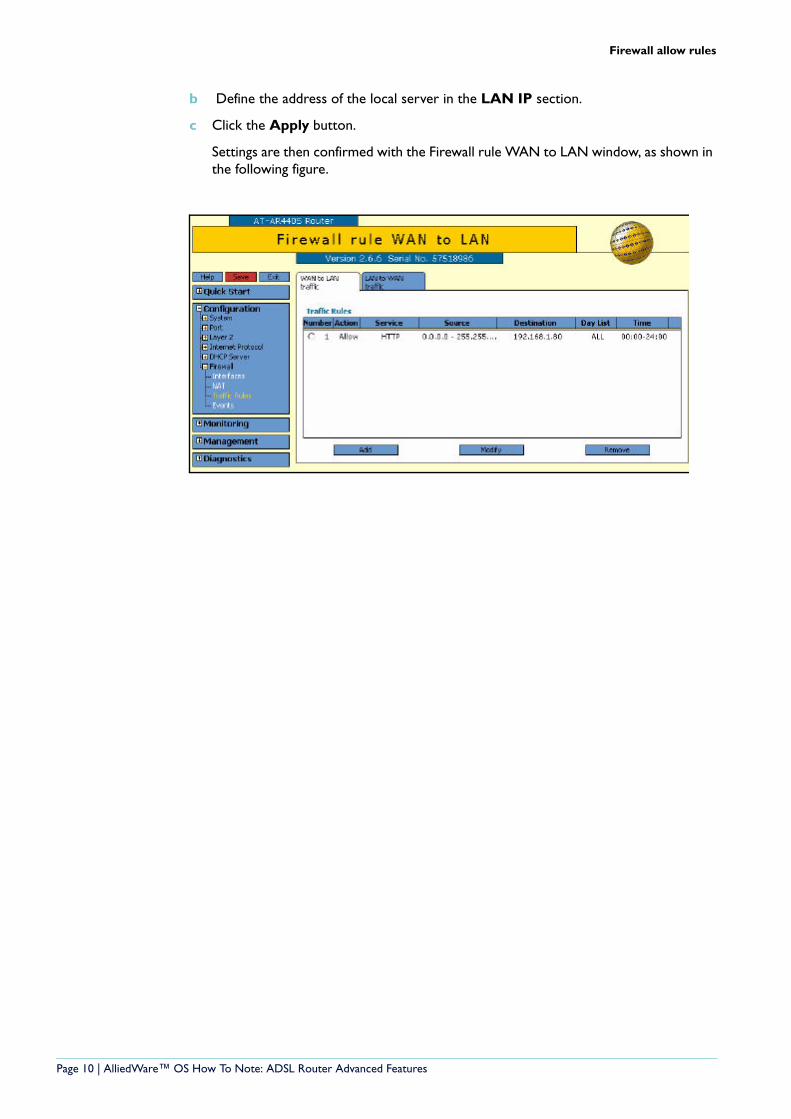
b Define the address of the local server in the LAN IP section.
c Click the Apply button.
Settings are then confirmed with the Firewall rule WAN to LAN window, as shown in the following figure.
Page 10 | AlliedWare™ OS How To Note: ADSL Router Advanced Features
Firewall allow rules
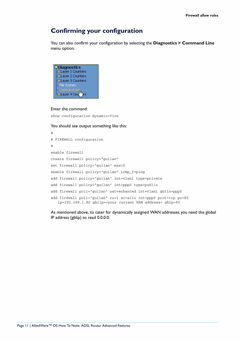
Confirming your configuration
You can also confirm your configuration by selecting the Diagnostics > Command Line menu option.
Enter the command:
show configuration dynamic=fire
You should see output something like this:
#
# FIREWALL configuration
#
enable firewall
create firewall policy="guilan"
set firewall policy="guilan" max=0
enable firewall policy="guilan" icmp_f=ping
add firewall policy="guilan" int=vlan1 type=private
add firewall policy="guilan" int=ppp0 type=public
add firewall poli="guilan" nat=enhanced int=vlan1 gblin=ppp0
add firewall poli="guilan" ru=1 ac=allo int=ppp0 prot=tcp po=80 ip=192.168.1.80 gblip=<your current WAN address> gblp=80
As mentioned above, to cater for dynamically assigned WAN addresses you need the global IP address (gblip) to read 0.0.0.0.
Page 11 | AlliedWare™ OS How To Note: ADSL Router Advanced Features
DHCP server
DHCP server
A DHCP Server provides the convenience of PCs automatically getting an IP address when they are plugged into your local office LAN network. The default factory configuration has a DHCP Server pre-configured. However, you may need to change the configuration to suit your network's IP addressing scheme.
Viewing the current DHCP server configuration
First, you can view your current configuration either with the GUI Diagnostics > Command line or with the GUI Configuration > DHCP Server > Configuration menu options.
To view the current firewall configuration via the Diagnostics > command line option, use the command:
show configuration dynamic=dhcp
You will get output something like this:
#
# DHCP configuration - Post IP
#
enable dhcp
create dhcp poli="lan-dhcp" lease=259200
add dhcp poli="lan-dhcp" subn=255.255.255.0
add dhcp poli="lan-dhcp" rou=192.168.1.1
add dhcp poli="lan-dhcp" dnss=192.168.1.1
create dhcp ran="standard" poli="lan-dhcp" ip=192.168.1.100 num=50
This configuration sets the DHCP Server up to allocate addresses in the range 192.168.1.100 - 192.168.1.149 to your local PCs. It also assigns the router address as the gateway and DNS Server. The router has a DNS Relay facility, therefore all the PCs on the LAN will send their DNS requests to the router, which then relay the requests to the external DNS Server.
Page 12 | AlliedWare™ OS How To Note: ADSL Router Advanced Features
DHCP server
Altering DHCP server configurations
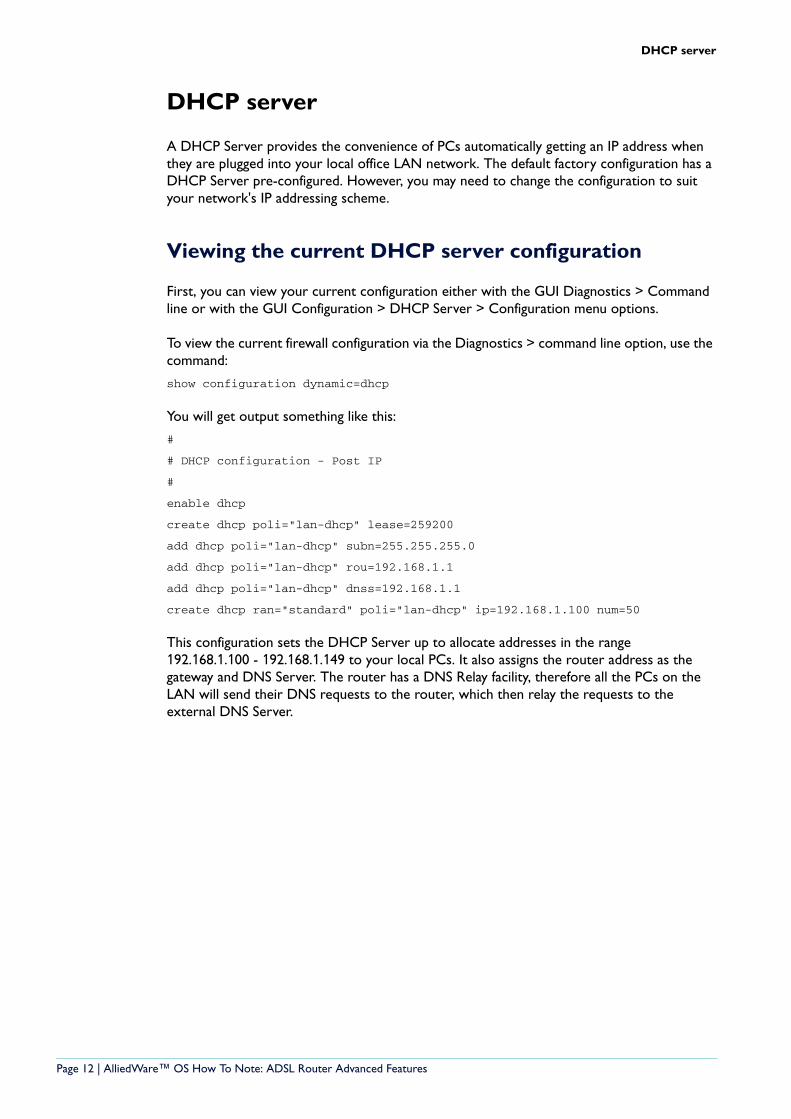
If you wish to alter this configuration, take the following steps using the GUI.
1. Select Configuration from the main side menu.
2. Select DHCP Server > Configuration.
The DHCP Server Configuration window opens.
3. To alter the DHCP policy, select the lan-dhcp policy name and click Modify.
Page 13 | AlliedWare™ OS How To Note: ADSL Router Advanced Features
DHCP server
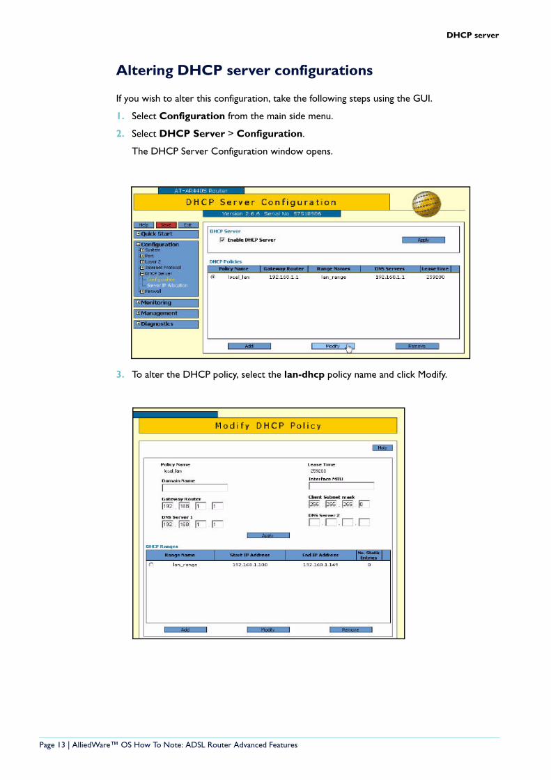
Note—If you need to change the IP range definition you will need to add a new range definition, and then remove the old ‘standard’ range definition.
4. After your configuration changes, you can confirm your changes are correct by selecting Diagnostics > Command Line.
Enter the command:
show configuration dynamic=dhcp
5. Save your configuration changes.
Page 14 | AlliedWare™ OS How To Note: ADSL Router Advanced Features
DNS Relay Configuration
DNS Relay Configuration
The default factory script also enables DNS Relay. The net effect of DNS relay is that your local PCs will make DNS queries to the router, and these queries are relayed to your ISP's Domain Name Server, which will resolve the query and reply. This is needed to work in with the default DHCP configuration and the PPP link dynamically assigned DNS details.
PPP dynamic assignment is often used over ADSL - if your ADSL provider uses PPPoA or PPPoEoA. If you use other ADSL link types, DNS Relay can still work after manually configuring your DNS addresses - refer to the figure below.
You can view your current DNS Relay configuration either with the GUI Diagnostics > Command Line or with the GUI Configuration > Internet Protocol > General menu options.
To view the current IP configuration via the diagnostics command line, use the command:
show configuration dynamic=ip
You will get output something like this:
#
# IP configuration
#
enable ip
enable ip remote
ena ip dnsrelay
add ip int=vlan1 ip=192.168.1.1
add ip int=ppp0 ip=0.0.0.0 mask=0.0.0.0
add ip rou=0.0.0.0 mask=0.0.0.0 int=ppp0 next=0.0.0.0
In here you can observe that ‘dnsrelay’ has been enabled.
Page 15 | AlliedWare™ OS How To Note: ADSL Router Advanced Features
DNS Relay Configuration
Enabling DNS relay using the GUI
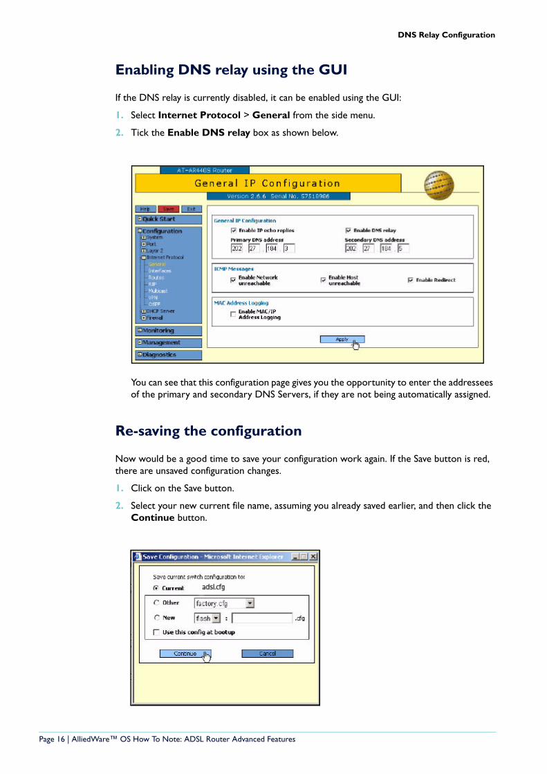
If the DNS relay is currently disabled, it can be enabled using the GUI:
1. Select Internet Protocol > General from the side menu.
2. Tick the Enable DNS relay box as shown below.
You can see that this configuration page gives you the opportunity to enter the addressees of the primary and secondary DNS Servers, if they are not being automatically assigned.
Re-saving the configuration
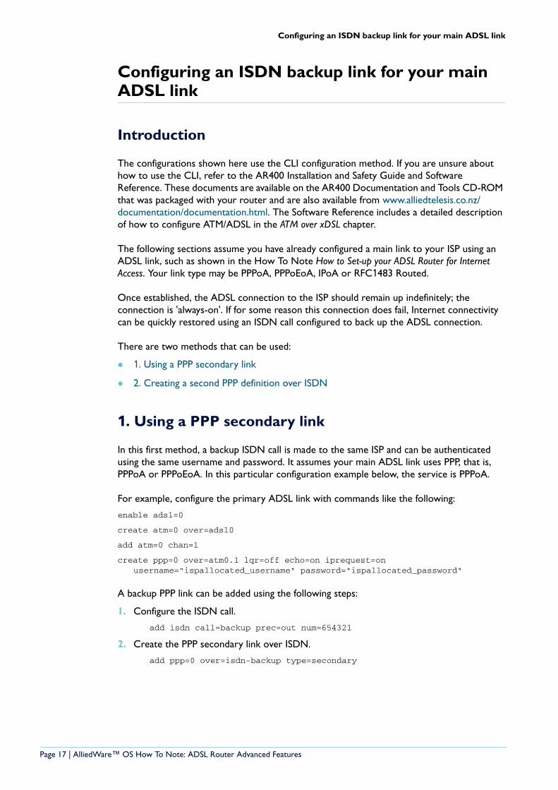
Now would be a good time to save your configuration work again. If the Save button is red, there are unsaved configuration changes.
1. Click on the Save button.
2. Select your new current file name, assuming you already saved earlier, and then click the Continue button.
Page 16 | AlliedWare™ OS How To Note: ADSL Router Advanced Features
Configuring an ISDN backup link for your main ADSL link
Configuring an ISDN backup link for your main ADSL link
Introduction
The configurations shown here use the CLI configuration method. If you are unsure about how to use the CLI, refer to the AR400 Installation and Safety Guide and Software Reference. These documents are available on the AR400 Documentation and Tools CD-ROM that was packaged with your router and are also available from www.alliedtelesis.co.nz/documentation/documentation.html. The Software Reference includes a detailed description of how to configure ATM/ADSL in the ATM over xDSL chapter.
The following sections assume you have already configured a main link to your ISP using an ADSL link, such as shown in the How To Note How to Set-up your ADSL Router for Internet Access. Your link type may be PPPoA, PPPoEoA, IPoA or RFC1483 Routed.
Once established, the ADSL connection to the ISP should remain up indefinitely; the connection is 'always-on'. If for some reason this connection does fail, Internet connectivity can be quickly restored using an ISDN call configured to back up the ADSL connection.
There are two methods that can be used:
1. Using a PPP secondary link
2. Creating a second PPP definition over ISDN
1. Using a PPP secondary link
In this first method, a backup ISDN call is made to the same ISP and can be authenticated using the same username and password. It assumes your main ADSL link uses PPP, that is, PPPoA or PPPoEoA. In this particular configuration example below, the service is PPPoA.
For example, configure the primary ADSL link with commands like the following:
enable adsl=0
create atm=0 over=adsl0
add atm=0 chan=1
create ppp=0 over=atm0.1 lqr=off echo=on iprequest=on username="ispallocated_username" password="ispallocated_password"
A backup PPP link can be added using the following steps:
1. Configure the ISDN call.
add isdn call=backup prec=out num=654321
2. Create the PPP secondary link over ISDN.
add ppp=0 over=isdn-backup type=secondary
Page 17 | AlliedWare™ OS How To Note: ADSL Router Advanced Features
Configuring an ISDN backup link for your main ADSL link
How the secondary PPP mechanism worksThe PPP module can monitor the quality of the link using either Link Quality Reporting (LQR) or LCP Echo Request/Reply messages (echo=on). Note that many ISPs use echo, not LQR—as shown in the configuration above.
If either method detects failure of the primary link, the PPP module will automatically activate the secondary link and traffic is redirected over the backup link.
PPP continually attempts to re-open the primary link, and when the primary link is restored, the backup call is deactivated and traffic is redirected over the primary link again.
2. Creating a second PPP definition over ISDN
In this second method, we set up a new separate PPP definition over the ISDN call definition, and we set up a second default route over this back-up PPP with a higher preference value. This means that the second route will only be used if the first route is unavailable.
Please note that this route preference solution can also be used when your main link is not using PPP. That is, it is valid for RFC 1483 Routed or IPoA links—both define an IP interface over ATM, with no PPP layer.
1. Configure the ISDN call
add isdn call=backup prec=out num=654321
2. Create the new PPP definition over ISDN. This PPP uses dial on demand, meaning that the ISDN call will only be activated if traffic is routed to this PPP, so we use "idle=300".
create ppp=1 idle=300 over=isdn-backup
set ppp=1 iprequest=on username=<isp-allocated_username>
set ppp=1 password=<isp-allocated_password>
set ppp=1 over=isdn-test lqr=off echo=10
3. Add the IP Interface and default route with higher preference value. (If there are two default routes, the one with lower preference is the preferred route.)
add ip int=ppp1 ip=0.0.0.0
add ip rou=0.0.0.0 mask=0.0.0.0 int=ppp1 next=0.0.0.0 pref=500
4. Add the new interface to the firewall, and define its NAT relationship. This ensures that your backup link is protected when used.
add firewall policy="guilan" int=ppp1 type=public
add firewall poli="guilan" nat=enhanced int=vlan1 gblin=ppp1
Page 18 | AlliedWare™ OS How To Note: ADSL Router Advanced Features
Configuring an ISDN backup link for your main ADSL link
How the higher preference route worksThe router is configured with two default routes to the Internet. The default route via the ADSL link has the lower preference value. Therefore, if this link is up, data will be sent down that route.
If the ADSL link goes down, then the associated IP interface and route are marked as not available. You can see this with the command "show ip route", as shown below. The first default route has a hash (#) by ppp0, indicating it is down.
Manager > show ip route
IP Routes----------------------------------------------------------------------------Destination Mask NextHop Interface AgeDLCI/Circ. Type Policy Protocol Metrics Preference----------------------------------------------------------------------------0.0.0.0 0.0.0.0 0.0.0.0 ppp0# 7556- direct 0 static 1 3600.0.0.0 0.0.0.0 0.0.0.0 ppp1 2463- direct 0 static 1 50050.50.50.5 255.255.255.255 0.0.0.0 ppp1 5529- direct 0 interface 1 0192.168.1.0 255.255.255.0 0.0.0.0 vlan1 7556- direct 0 interface 1 0----------------------------------------------------------------------------
Even if the connection over the ADSL link uses IPoA or RFC 1483 routed, and the ADSL link goes down, the route via that interface will be deemed inactive.
At this point, data will be sent over the higher preference default route definition, because it is now the best route available. This route is only used if the main route is unavailable, because it has a higher preference value. When the route is used, it causes the dial-on-demand ISDN call to be activated, and so PPP1 will open, providing a back-up route to the Internet.
When the ADSL link is restored, the route via the ADSL interface will become active again. Data will then prefer to use that route as it has a lower preference value. PPP1 (the ISDN call) will disconnect after the idle period—the example above uses a 300 second idle period.
Avoiding unnecessary ISDN calls at router start-upOne point that needs to be considered in the context of this ‘alternative route’ solution is the fact that the ADSL link typically takes up to 30 seconds to become established after the router start-up. So, for the first 30 seconds or so after start-up, the route via the ADSL link is inactive, therefore Internet-directed data would cause the ISDN call to be activated. If you don’t want this to occur, then you can force the ISDN call to be ‘held down’ for the first 30 seconds or so after router start-up. This is achieved by means of a restart trigger:
enable trigger
create trigger=1 reboot=all script=holdisdn.scp
The contents of the file holdisdn.scp are:
disable ppp=1
wait 40
enable ppp=1
Page 19 | AlliedWare™ OS How To Note: ADSL Router Advanced Features
Configuring an ISDN backup link for your main ADSL link
Verifying your back-up link
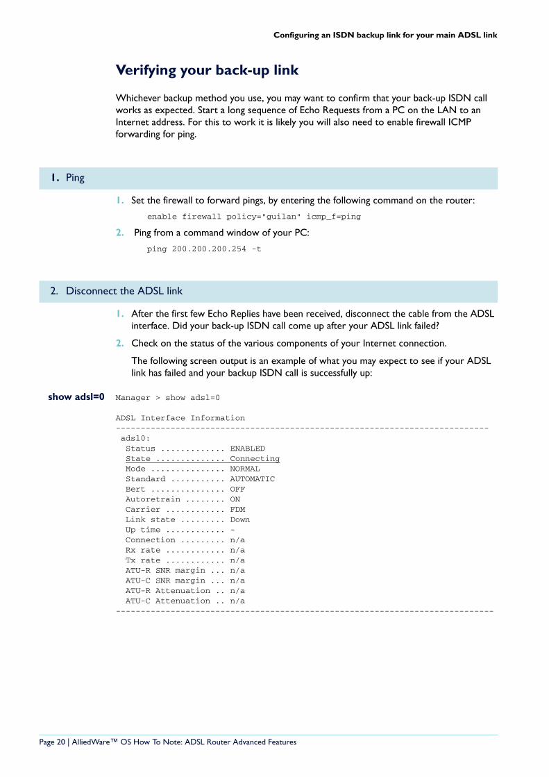
Whichever backup method you use, you may want to confirm that your back-up ISDN call works as expected. Start a long sequence of Echo Requests from a PC on the LAN to an Internet address. For this to work it is likely you will also need to enable firewall ICMP forwarding for ping.
1. Set the firewall to forward pings, by entering the following command on the router:
enable firewall policy="guilan" icmp_f=ping
2. Ping from a command window of your PC:
ping 200.200.200.254 -t
1. After the first few Echo Replies have been received, disconnect the cable from the ADSL interface. Did your back-up ISDN call come up after your ADSL link failed?
2. Check on the status of the various components of your Internet connection.
The following screen output is an example of what you may expect to see if your ADSL link has failed and your backup ISDN call is successfully up:
show adsl=0 Manager > show adsl=0
ADSL Interface Information--------------------------------------------------------------------------- adsl0: Status ............. ENABLED State .............. Connecting Mode ............... NORMAL Standard ........... AUTOMATIC Bert ............... OFF Autoretrain ........ ON Carrier ............ FDM Link state ......... Down Up time ............ - Connection ......... n/a Rx rate ............ n/a Tx rate ............ n/a ATU-R SNR margin ... n/a ATU-C SNR margin ... n/a ATU-R Attenuation .. n/a ATU-C Attenuation .. n/a----------------------------------------------------------------------------
1. Ping
2. Disconnect the ADSL link
Page 20 | AlliedWare™ OS How To Note: ADSL Router Advanced Features
Configuring an ISDN backup link for your main ADSL link
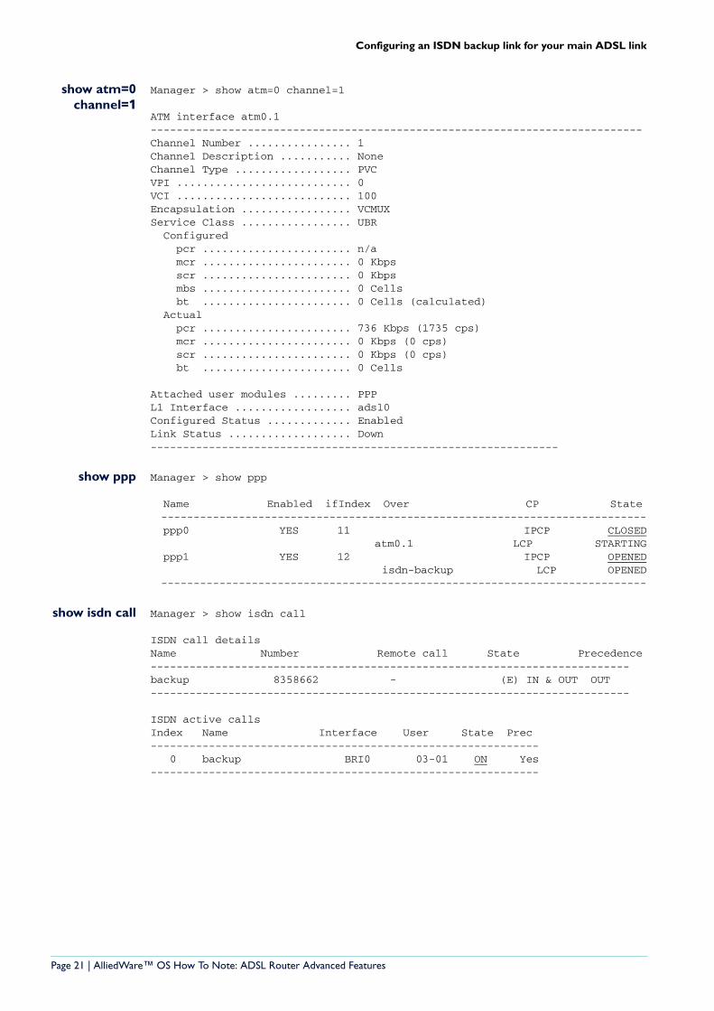
show atm=0channel=1
Manager > show atm=0 channel=1
ATM interface atm0.1----------------------------------------------------------------------------Channel Number ................ 1Channel Description ........... NoneChannel Type .................. PVCVPI ........................... 0VCI ........................... 100Encapsulation ................. VCMUXService Class ................. UBR Configured pcr ....................... n/a mcr ....................... 0 Kbps scr ....................... 0 Kbps mbs ....................... 0 Cells bt ....................... 0 Cells (calculated) Actual pcr ....................... 736 Kbps (1735 cps) mcr ....................... 0 Kbps (0 cps) scr ....................... 0 Kbps (0 cps) bt ....................... 0 Cells
Attached user modules ......... PPPL1 Interface .................. adsl0Configured Status ............. EnabledLink Status ................... Down---------------------------------------------------------------
show ppp Manager > show ppp
Name Enabled ifIndex Over CP State --------------------------------------------------------------------------- ppp0 YES 11 IPCP CLOSED atm0.1 LCP STARTING ppp1 YES 12 IPCP OPENED isdn-backup LCP OPENED ---------------------------------------------------------------------------
show isdn call Manager > show isdn call
ISDN call detailsName Number Remote call State Precedence--------------------------------------------------------------------------backup 8358662 - (E) IN & OUT OUT--------------------------------------------------------------------------
ISDN active callsIndex Name Interface User State Prec------------------------------------------------------------ 0 backup BRI0 03-01 ON Yes------------------------------------------------------------
Page 21 | AlliedWare™ OS How To Note: ADSL Router Advanced Features
Configuring an ISDN backup link for your main ADSL link
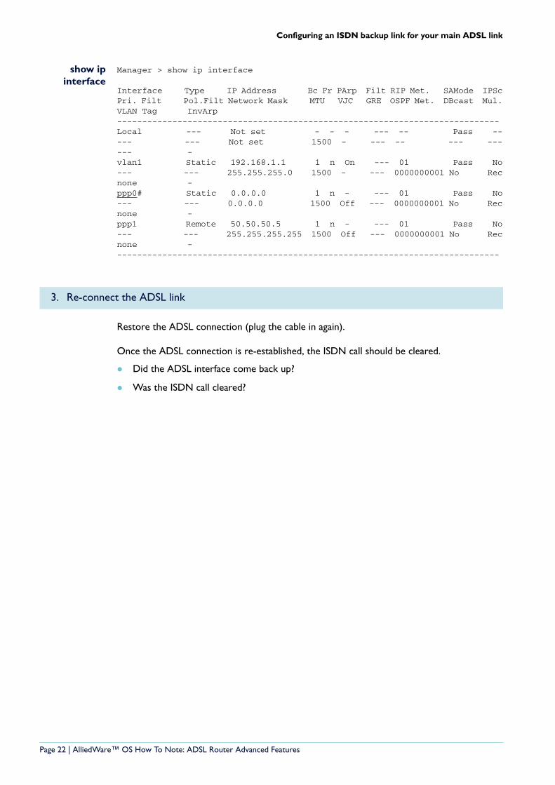
show ipinterface
Manager > show ip interface
Interface Type IP Address Bc Fr PArp Filt RIP Met. SAMode IPScPri. Filt Pol.Filt Network Mask MTU VJC GRE OSPF Met. DBcast Mul.VLAN Tag InvArp----------------------------------------------------------------------------Local --- Not set - - - --- -- Pass ----- --- Not set 1500 - --- -- --- ------ -vlan1 Static 192.168.1.1 1 n On --- 01 Pass No--- --- 255.255.255.0 1500 - --- 0000000001 No Recnone -ppp0# Static 0.0.0.0 1 n - --- 01 Pass No--- --- 0.0.0.0 1500 Off --- 0000000001 No Recnone -ppp1 Remote 50.50.50.5 1 n - --- 01 Pass No--- --- 255.255.255.255 1500 Off --- 0000000001 No Recnone -----------------------------------------------------------------------------
Restore the ADSL connection (plug the cable in again).
Once the ADSL connection is re-established, the ISDN call should be cleared.
Did the ADSL interface come back up?
Was the ISDN call cleared?
3. Re-connect the ADSL link
Page 22 | AlliedWare™ OS How To Note: ADSL Router Advanced Features
IPsec VPN with NAT-T
IPsec VPN with NAT-T
One very useful application for the router is to provide an IPsec gateway to enable remote teleworkers to have a secure connection across the Internet to their office LAN.
Allied Telesis offers How To Notes with a wide range of VPN solutions, from quick and simple solutions for connecting home and remote offices, to advanced multi-feature setups. Notes also describe how to create a VPN between an Allied Telesis router and equipment from a number of other vendors.
For a complete list of VPN How To Notes, see the Overview of VPN Solutions in How To Notes in the How To Library at www.alliedtelesis.com/resources/literature/howto.aspx.
The collection includes Notes that describe how to interoperate with Windows 2000, XP and Vista clients.
An IPsec VPN client comes as a standard component of Microsoft® Windows XP, so it is now very easy to set up a PC to make a secure connection across the Internet. What is more, the IPsec VPN client in Microsoft® Windows XP includes the NAT-T feature, which means that even if the teleworker’s PC is behind a NATing firewall, the VPN connection will still work.
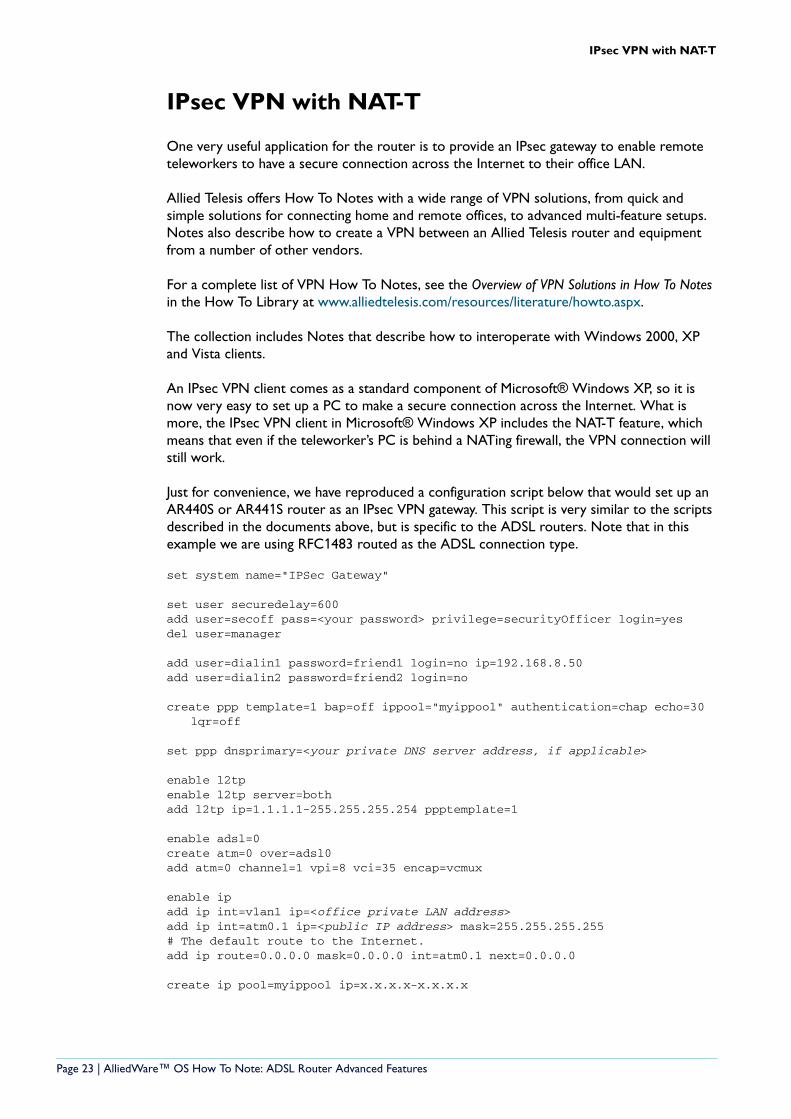
Just for convenience, we have reproduced a configuration script below that would set up an AR440S or AR441S router as an IPsec VPN gateway. This script is very similar to the scripts described in the documents above, but is specific to the ADSL routers. Note that in this example we are using RFC1483 routed as the ADSL connection type.
set system name="IPSec Gateway"
set user securedelay=600add user=secoff pass=<your password> privilege=securityOfficer login=yesdel user=manager
add user=dialin1 password=friend1 login=no ip=192.168.8.50add user=dialin2 password=friend2 login=no
create ppp template=1 bap=off ippool="myippool" authentication=chap echo=30 lqr=off
set ppp dnsprimary=<your private DNS server address, if applicable>
enable l2tpenable l2tp server=bothadd l2tp ip=1.1.1.1-255.255.255.254 ppptemplate=1
enable adsl=0create atm=0 over=adsl0add atm=0 channel=1 vpi=8 vci=35 encap=vcmux
enable ipadd ip int=vlan1 ip=<office private LAN address>add ip int=atm0.1 ip=<public IP address> mask=255.255.255.255# The default route to the Internet.add ip route=0.0.0.0 mask=0.0.0.0 int=atm0.1 next=0.0.0.0
create ip pool=myippool ip=x.x.x.x-x.x.x.x
Page 23 | AlliedWare™ OS How To Note: ADSL Router Advanced Features

IPsec VPN with NAT-T
enable firecreate fire policy=maincreate fire policy=main dy=dynamicadd fire policy=main dy=dynamic user=ANYadd fire policy=main int=vlan1 type=privateadd fire policy=main int=dyn-dynamic type=privateadd fire policy=main int=atm0.1 type=publicadd fire policy=main nat=enhanced int=vlan1 gblinterface=atm0.1add fire policy=main nat=enhanced int=dyn-dynamic gblinterface=atm0.1
add fire policy=main rule=1 int=atm0.1 action=allow protocol=udp ip=<Public IP address> port=500 gblip=<Public IP address> gblport=500
add fire policy=main rule=2 int=atm0.1 action=allow protocol=udp ip=<Public IP address> port=4500 gblip=<Public IP address> gblport=4500
add fire policy=main rule=3 int=atm0.1 action=allow prot=udp ip=<Public IP address> port=1701 gblip=<Public IP address> gblport=1701 encap=ipsec
enable ssh server serverkey=2 hostkey=3 expirytime=12 logintimeout=60add ssh user=secoff password=<secoff password>
ipaddress=<trusted remote ip address>
cre ipsec saspecification=1 key=isakmp protocol=esp encalg=3desouterhashalg=sha mode=transport
cre ipsec saspecification=2 key=isakmp protocol=esp encalg=3desouter hashalg=md5 mode=transport
cre ipsec saspecification=3 key=isakmp protocol=esp encalg=des hashalg=sha mode=transport
cre ipsec sas=4 key=isakmp protocol=esp encalg=des hashalg=md5mode=transport
create ipsec bundle=1 key=isakmp string="1 or 2 or 3 or 4"create ipsec policy="isakmp" int=atm0.1 ac=permitset ipsec policy="isakmp" lp=500create ipsec policy="isakmp_float" int=atm0.1 action=permitset ipsec policy="isakmp_float" lport=4500create ipsec policy="all_roaming" int=atm0.1 action=ipsec key=isakmp
bundlespecification=1 isakmppolicy="roaming1" peer=anyset ipsec policy="all_roaming" transport=udp lport=1701create ipsec policy="internet" int=atm0.1 action=permitenable ipsec
Page 24 | AlliedWare™ OS How To Note: ADSL Router Advanced Features
How to troubleshoot your ADSL connection
How to troubleshoot your ADSL connection
IntroductionAre you having trouble establishing your ADSL connection or unable to access the Internet? Here are some steps you can take to find the problem:
First, we would like you to review an initial checklist of possible set up problems.
If all items in the initial checklist are OK, then we need to check your connection, starting at the underlying ADSL connection and then moving up through the network layers to find the point of failure.
Most of the work in the advanced troubleshooting process uses the Command Line Interface (CLI). This can be accessed either by using a serial console access or by Telnet access. If you are unsure about how to use the CLI, refer to the AR400 Installation and Safety Guide and Software Reference. These documents are available on the AR400 Documentation and Tools CD-ROM that was packaged with your router and are also available from www.alliedtelesis.co.nz/documentation/documentation.html. The Software Reference includes a detailed description of how to configure ATM/ADSL in the ATM over xDSL chapter.
Basic troubleshooting—initial checklistIf you are failing to access the Internet via your ADSL router, then start the troubleshooting process by working through the steps described below:
1. Could you access the router's GUI successfully? If not, then check whether your PC is correctly set up, by following the steps in "Appendix B: Checking if your PC is correctly configured" on page 37.
2. Are your Internet browser's proxy settings disabled? If not, then disable them, as shown in the How To Note, How to set up your ADSL router for Internet access.
3. Has your Firewall NAT been properly enabled? Check that the Enable Firewall option has been selected on the page invoked by Quick Start > ADSL
4. Did you correctly save your configuration, and tick to indicate this configuration should be used at bootup? If not, your configuration could be lost when your router loses power.
5. Have you altered your default firewall configuration, such as adding new allow rules? If so, then try removing these changes, and see if Internet access is restored.
6. Is DNS Relay properly enabled, and have you got correct DNS address details for your ISP, either from dynamic assignment or static configuration? Check the settings as shown in "Enabling DNS relay using the GUI" on page 16 of this document.
If you have been through all these steps and not discovered the reason for the inability to access the Internet, then move on to the advanced troubleshooting process described below.
Page 25 | AlliedWare™ OS How To Note: ADSL Router Advanced Features
How to troubleshoot your ADSL connection
Advanced troubleshooting 1: check the ADSL layer
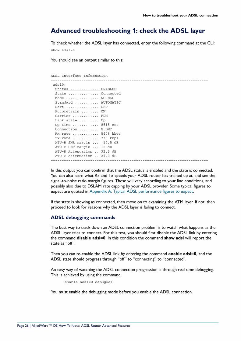
To check whether the ADSL layer has connected, enter the following command at the CLI:
show adsl=0
You should see an output similar to this:
ADSL Interface Information------------------------------------------------------------------------ adsl0: Status ............. ENABLED State .............. Connected Mode ............... NORMAL Standard ........... AUTOMATIC Bert ............... OFF Autoretrain ........ ON Carrier ............ FDM Link state ......... Up Up time ............ 8515 sec Connection ......... G.DMT Rx rate ............ 5408 kbps Tx rate ............ 736 kbps ATU-R SNR margin ... 14.5 dB ATU-C SNR margin ... 12 dB ATU-R Attenuation .. 32.5 dB ATU-C Attenuation .. 27.0 dB------------------------------------------------------------------------
In this output you can confirm that the ADSL status is enabled and the state is connected. You can also learn what Rx and Tx speeds your ADSL router has trained up at, and see the signal-to-noise ratio margin figures. These will vary according to your line conditions, and possibly also due to DSLAM rate capping by your ADSL provider. Some typical figures to expect are quoted in Appendix A: Typical ADSL performance figures to expect.
If the state is showing as connected, then move on to examining the ATM layer. If not, then proceed to look for reasons why the ADSL layer is failing to connect.
ADSL debugging commands
The best way to track down an ADSL connection problem is to watch what happens as the ADSL layer tries to connect. For this test, you should first disable the ADSL link by entering the command disable adsl=0. In this condition the command show adsl will report the state as “off”.
Then you can re-enable the ADSL link by entering the command enable adsl=0, and the ADSL state should progress through “off” to “connecting” to “connected”.
An easy way of watching the ADSL connection progression is through real-time debugging. This is achieved by using the command:
enable adsl=0 debug=all
You must enable the debugging mode before you enable the ADSL connection.
Page 26 | AlliedWare™ OS How To Note: ADSL Router Advanced Features
How to troubleshoot your ADSL connection
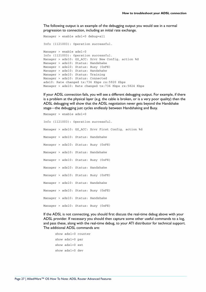
The following output is an example of the debugging output you would see in a normal progression to connection, including an initial rate exchange.
Manager > enable adsl=0 debug=all
Info (1121003): Operation successful.
Manager > enable adsl=0Info (1121003): Operation successful.Manager > adsl0: GS_ACC: Xcvr New Config, action %dManager > adsl0: Status: HandshakeManager > adsl0: Status: Busy (0xFE)Manager > adsl0: Status: HandshakeManager > adsl0: Status: TrainingManager > adsl0: Status: Connectedadsl0: Rate changed tx:736 Kbps rx:5920 KbpsManager > adsl0: Rate changed tx:736 Kbps rx:5824 Kbps
If your ADSL connection fails, you will see a different debugging output. For example, if there is a problem at the physical layer (e.g. the cable is broken, or is a very poor quality) then the ADSL debugging will show that the ADSL negotiation never gets beyond the Handshake stage—the debugging just cycles endlessly between Handshaking and Busy.
Manager > enable adsl=0
Info (1121003): Operation successful.
Manager > adsl0: GS_ACC: Xcvr First Config, action %d
Manager > adsl0: Status: Handshake
Manager > adsl0: Status: Busy (0xFE)
Manager > adsl0: Status: Handshake
Manager > adsl0: Status: Busy (0xFE)
Manager > adsl0: Status: Handshake
Manager > adsl0: Status: Busy (0xFE)
Manager > adsl0: Status: Handshake
Manager > adsl0: Status: Busy (0xFE)
Manager > adsl0: Status: Handshake
Manager > adsl0: Status: Busy (0xFE)
If the ADSL is not connecting, you should first discuss the real-time debug above with your ADSL provider. If necessary you should then capture some other useful commands to a log, and pass these, along with the real-time debug, to your ATI distributor for technical support. The additional ADSL commands are:
show adsl=0 counter
show adsl=0 par
show adsl=0 ext
show adsl=0 dev
Page 27 | AlliedWare™ OS How To Note: ADSL Router Advanced Features
How to troubleshoot your ADSL connection
Advanced troubleshooting 2: check the ATM Layer
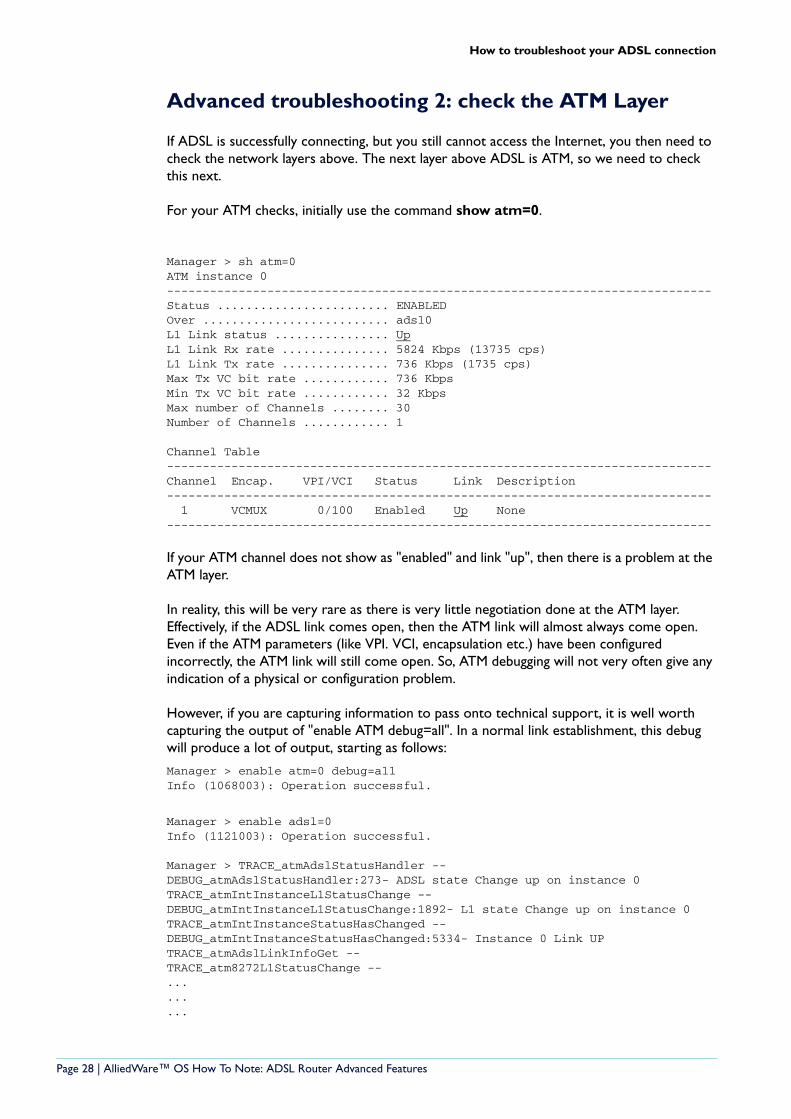
If ADSL is successfully connecting, but you still cannot access the Internet, you then need to check the network layers above. The next layer above ADSL is ATM, so we need to check this next.
For your ATM checks, initially use the command show atm=0.
Manager > sh atm=0ATM instance 0----------------------------------------------------------------------------Status ........................ ENABLEDOver .......................... adsl0L1 Link status ................ UpL1 Link Rx rate ............... 5824 Kbps (13735 cps)L1 Link Tx rate ............... 736 Kbps (1735 cps)Max Tx VC bit rate ............ 736 KbpsMin Tx VC bit rate ............ 32 KbpsMax number of Channels ........ 30Number of Channels ............ 1
Channel Table----------------------------------------------------------------------------Channel Encap. VPI/VCI Status Link Description---------------------------------------------------------------------------- 1 VCMUX 0/100 Enabled Up None----------------------------------------------------------------------------
If your ATM channel does not show as "enabled" and link "up", then there is a problem at the ATM layer.
In reality, this will be very rare as there is very little negotiation done at the ATM layer. Effectively, if the ADSL link comes open, then the ATM link will almost always come open. Even if the ATM parameters (like VPI. VCI, encapsulation etc.) have been configured incorrectly, the ATM link will still come open. So, ATM debugging will not very often give any indication of a physical or configuration problem.
However, if you are capturing information to pass onto technical support, it is well worth capturing the output of "enable ATM debug=all". In a normal link establishment, this debug will produce a lot of output, starting as follows:
Manager > enable atm=0 debug=allInfo (1068003): Operation successful.
Manager > enable adsl=0Info (1121003): Operation successful.
Manager > TRACE_atmAdslStatusHandler --DEBUG_atmAdslStatusHandler:273- ADSL state Change up on instance 0TRACE_atmIntInstanceL1StatusChange --DEBUG_atmIntInstanceL1StatusChange:1892- L1 state Change up on instance 0TRACE_atmIntInstanceStatusHasChanged --DEBUG_atmIntInstanceStatusHasChanged:5334- Instance 0 Link UPTRACE_atmAdslLinkInfoGet --TRACE_atm8272L1StatusChange --.........
Page 28 | AlliedWare™ OS How To Note: ADSL Router Advanced Features
How to troubleshoot your ADSL connection
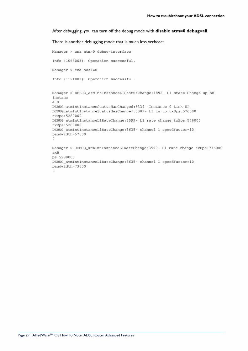
After debugging, you can turn off the debug mode with disable atm=0 debug=all.
There is another debugging mode that is much less verbose:
Manager > ena atm=0 debug=interface
Info (1068003): Operation successful.
Manager > ena adsl=0
Info (1121003): Operation successful.
Manager > DEBUG_atmIntInstanceL1StatusChange:1892- L1 state Change up on instance 0DEBUG_atmIntInstanceStatusHasChanged:5334- Instance 0 Link UPDEBUG_atmIntInstanceStatusHasChanged:5389- L1 is up txBps:576000 rxBps:5280000DEBUG_atmIntInstanceL1RateChange:3599- L1 rate change txBps:576000 rxBps:5280000DEBUG_atmIntInstanceL1RateChange:3635- channel 1 speedFactor=10, bandwidth=576000
Manager > DEBUG_atmIntInstanceL1RateChange:3599- L1 rate change txBps:736000 rxBps:5280000DEBUG_atmIntInstanceL1RateChange:3635- channel 1 speedFactor=10, bandwidth=736000
Page 29 | AlliedWare™ OS How To Note: ADSL Router Advanced Features
How to troubleshoot your ADSL connection
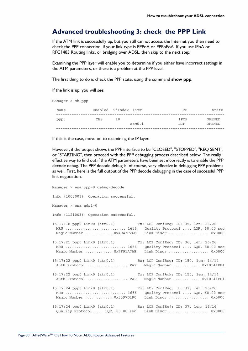
Advanced troubleshooting 3: check the PPP LinkIf the ATM link is successfully up, but you still cannot access the Internet you then need to check the PPP connection, if your link type is PPPoA or PPPoEoA. If you use IPoA or RFC1483 Routing links, or bridging over ADSL, then skip to the next step.
Examining the PPP layer will enable you to determine if you either have incorrect settings in the ATM parameters, or there is a problem at the PPP level.
The first thing to do is check the PPP state, using the command show ppp.
If the link is up, you will see:
Manager > sh ppp
Name Enabled ifIndex Over CP State --------------------------------------------------------------------------- ppp0 YES 10 IPCP OPENED atm0.1 LCP OPENED ---------------------------------------------------------------------------
If this is the case, move on to examining the IP layer.
However, if the output shows the PPP interface to be "CLOSED", "STOPPED", "REQ SENT", or "STARTING", then proceed with the PPP debugging process described below. The really effective way to find out if the ATM parameters have been set incorrectly is to enable the PPP decode debug. The PPP decode debug is, of course, very effective in debugging PPP problems as well. First, here is the full output of the PPP decode debugging in the case of successful PPP link negotiation.
Manager > ena ppp=0 debug=decode
Info (1003003): Operation successful.
Manager > ena adsl=0
Info (1121003): Operation successful.
15:17:18 ppp0 Link0 (atm0.1) Tx: LCP ConfReq: ID: 35, len: 26/26 MRU ........................... 1656 Quality Protocol .... LQR, 60.00 sec Magic Number ............ 0x4943C26D Link Discr .................. 0x0000
15:17:21 ppp0 Link0 (atm0.1) Tx: LCP ConfReq: ID: 36, len: 26/26 MRU ........................... 1656 Quality Protocol .... LQR, 60.00 sec Magic Number ............ 0x7F91A7AE Link Discr .................. 0x0000
15:17:22 ppp0 Link0 (atm0.1) Rx: LCP ConfReq: ID: 150, len: 14/14 Auth Protocol .................. PAP Magic Number ............ 0x10141FB1
15:17:22 ppp0 Link0 (atm0.1) Tx: LCP ConfAck: ID: 150, len: 14/14 Auth Protocol .................. PAP Magic Number ............ 0x10141FB1
15:17:24 ppp0 Link0 (atm0.1) Tx: LCP ConfReq: ID: 37, len: 26/26 MRU ........................... 1656 Quality Protocol .... LQR, 60.00 sec Magic Number ............ 0x3397D1F0 Link Discr .................. 0x0000
15:17:24 ppp0 Link0 (atm0.1) Rx: LCP ConfRej: ID: 37, len: 16/16 Quality Protocol .... LQR, 60.00 sec Link Discr .................. 0x0000
Page 30 | AlliedWare™ OS How To Note: ADSL Router Advanced Features

How to troubleshoot your ADSL connection
15:17:24 ppp0 Link0 (atm0.1) Tx: LCP ConfReq: ID: 38, len: 14/14 MRU ........................... 1656 Magic Number ............ 0x3397D1F0
15:17:24 ppp0 Link0 (atm0.1) Rx: LCP ConfAck: ID: 38, len: 14/14 MRU ........................... 1656 Magic Number ............ 0x3397D1F0
-----End of LCP negotiation----------------
15:17:24 ppp0 Peer: Transmitting PAP request15:17:24 ppp0 Peer: Received PAP ACK15:17:24 ppp0 Peer: PAP authentication succeeded
-----End of authentication-----------------
15:17:24 ppp0 Link0 (atm0.1) Tx: IPCP ConfReq: ID: 40, len: 22/22 IP Address ................. 0.0.0.0 Primary DNS Addr ........... 0.0.0.0 Second DNS Addr ............ 0.0.0.0
15:17:24 ppp0 Link0 (atm0.1) Rx: IPCP ConfNack: ID: 40, len: 22/22 IP Address ......... 222.152.249.201 Primary DNS Addr ...... 202.27.184.3 Second DNS Addr ....... 202.27.184.5
15:17:24 ppp0 Link0 (atm0.1) Tx: IPCP ConfReq: ID: 41, len: 22/22 IP Address ......... 222.152.249.201 Primary DNS Addr ...... 202.27.184.3 Second DNS Addr ....... 202.27.184.5
15:17:24 ppp0 Link0 (atm0.1) Rx: IPCP ConfAck: ID: 41, len: 22/22 IP Address ......... 222.152.249.201 Primary DNS Addr ...... 202.27.184.3 Second DNS Addr ....... 202.27.184.5
15:17:24 ppp0 Link0 (atm0.1) Rx: IPCP ConfReq: ID: 241, len: 10/10 IP Address ........... 222.152.216.1
15:17:24 ppp0 Link0 (atm0.1) Tx: IPCP ConfAck: ID: 241, len: 10/10 IP Address ........... 222.152.216.1
-----End of IPCP authentication - the PPP link is now fully OPEN
Page 31 | AlliedWare™ OS How To Note: ADSL Router Advanced Features
How to troubleshoot your ADSL connection
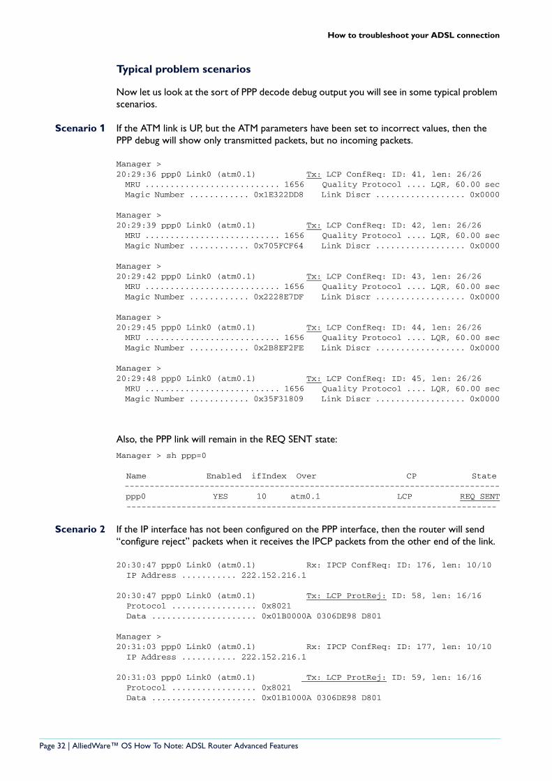
Typical problem scenarios
Now let us look at the sort of PPP decode debug output you will see in some typical problem scenarios.
Scenario 1 If the ATM link is UP, but the ATM parameters have been set to incorrect values, then the PPP debug will show only transmitted packets, but no incoming packets.
Manager > 20:29:36 ppp0 Link0 (atm0.1) Tx: LCP ConfReq: ID: 41, len: 26/26 MRU ........................... 1656 Quality Protocol .... LQR, 60.00 sec Magic Number ............ 0x1E322DD8 Link Discr .................. 0x0000
Manager > 20:29:39 ppp0 Link0 (atm0.1) Tx: LCP ConfReq: ID: 42, len: 26/26 MRU ........................... 1656 Quality Protocol .... LQR, 60.00 sec Magic Number ............ 0x705FCF64 Link Discr .................. 0x0000
Manager > 20:29:42 ppp0 Link0 (atm0.1) Tx: LCP ConfReq: ID: 43, len: 26/26 MRU ........................... 1656 Quality Protocol .... LQR, 60.00 sec Magic Number ............ 0x2228E7DF Link Discr .................. 0x0000
Manager > 20:29:45 ppp0 Link0 (atm0.1) Tx: LCP ConfReq: ID: 44, len: 26/26 MRU ........................... 1656 Quality Protocol .... LQR, 60.00 sec Magic Number ............ 0x2B8EF2FE Link Discr .................. 0x0000
Manager > 20:29:48 ppp0 Link0 (atm0.1) Tx: LCP ConfReq: ID: 45, len: 26/26 MRU ........................... 1656 Quality Protocol .... LQR, 60.00 sec Magic Number ............ 0x35F31809 Link Discr .................. 0x0000
Also, the PPP link will remain in the REQ SENT state:
Manager > sh ppp=0
Name Enabled ifIndex Over CP State --------------------------------------------------------------------------- ppp0 YES 10 atm0.1 LCP REQ SENT --------------------------------------------------------------------------
Scenario 2 If the IP interface has not been configured on the PPP interface, then the router will send “configure reject” packets when it receives the IPCP packets from the other end of the link.
20:30:47 ppp0 Link0 (atm0.1) Rx: IPCP ConfReq: ID: 176, len: 10/10 IP Address ........... 222.152.216.1
20:30:47 ppp0 Link0 (atm0.1) Tx: LCP ProtRej: ID: 58, len: 16/16 Protocol ................. 0x8021 Data ..................... 0x01B0000A 0306DE98 D801
Manager > 20:31:03 ppp0 Link0 (atm0.1) Rx: IPCP ConfReq: ID: 177, len: 10/10 IP Address ........... 222.152.216.1
20:31:03 ppp0 Link0 (atm0.1) Tx: LCP ProtRej: ID: 59, len: 16/16 Protocol ................. 0x8021 Data ..................... 0x01B1000A 0306DE98 D801
Page 32 | AlliedWare™ OS How To Note: ADSL Router Advanced Features
How to troubleshoot your ADSL connection
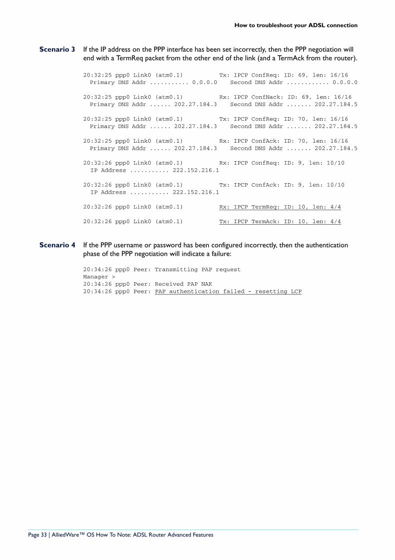
Scenario 3 If the IP address on the PPP interface has been set incorrectly, then the PPP negotiation will end with a TermReq packet from the other end of the link (and a TermAck from the router).
20:32:25 ppp0 Link0 (atm0.1) Tx: IPCP ConfReq: ID: 69, len: 16/16 Primary DNS Addr ........... 0.0.0.0 Second DNS Addr ............ 0.0.0.0
20:32:25 ppp0 Link0 (atm0.1) Rx: IPCP ConfNack: ID: 69, len: 16/16 Primary DNS Addr ...... 202.27.184.3 Second DNS Addr ....... 202.27.184.5
20:32:25 ppp0 Link0 (atm0.1) Tx: IPCP ConfReq: ID: 70, len: 16/16 Primary DNS Addr ...... 202.27.184.3 Second DNS Addr ....... 202.27.184.5
20:32:25 ppp0 Link0 (atm0.1) Rx: IPCP ConfAck: ID: 70, len: 16/16 Primary DNS Addr ...... 202.27.184.3 Second DNS Addr ....... 202.27.184.5
20:32:26 ppp0 Link0 (atm0.1) Rx: IPCP ConfReq: ID: 9, len: 10/10 IP Address ........... 222.152.216.1
20:32:26 ppp0 Link0 (atm0.1) Tx: IPCP ConfAck: ID: 9, len: 10/10 IP Address ........... 222.152.216.1
20:32:26 ppp0 Link0 (atm0.1) Rx: IPCP TermReq: ID: 10, len: 4/4
20:32:26 ppp0 Link0 (atm0.1) Tx: IPCP TermAck: ID: 10, len: 4/4
Scenario 4 If the PPP username or password has been configured incorrectly, then the authentication phase of the PPP negotiation will indicate a failure:
20:34:26 ppp0 Peer: Transmitting PAP requestManager > 20:34:26 ppp0 Peer: Received PAP NAK20:34:26 ppp0 Peer: PAP authentication failed - resetting LCP
Page 33 | AlliedWare™ OS How To Note: ADSL Router Advanced Features
How to troubleshoot your ADSL connection
Advanced troubleshooting 4: check the IP layer
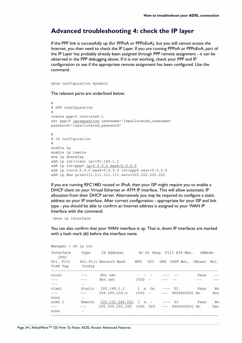
If the PPP link is successfully up (for PPPoA or PPPoEoA), but you still cannot access the Internet, you then need to check the IP Layer. If you are running PPPoA or PPPoEoA, part of the IP Layer has probably already been assigned through PPP remote assignment - it can be observed in the PPP debugging above. If it is not working, check your PPP and IP configuration to see if the appropriate remote assignment has been configured. Use the command:
show configuration dynamic
The relevant parts are underlined below:
## PPP configuration#create ppp=0 over=atm0.1set ppp=0 iprequest=on username="ispallocated_username" password="ispallocated_password"
## IP configuration#enable ipenable ip remoteena ip dnsrelayadd ip int=vlan1 ip=192.168.1.1add ip int=ppp0 ip=0.0.0.0 mask=0.0.0.0add ip rou=0.0.0.0 mask=0.0.0.0 int=ppp0 next=0.0.0.0 add ip dns prim=111.111.111.111 seco=222.222.222.222
If you are running RFC1483 routed or IPoA, then your ISP might require you to enable a DHCP client on your Virtual Ethernet or ATM IP interface. This will allow automatic IP allocation from their DHCP server. Alternatively you may be required to configure a static address on your IP interface. After correct configuration - appropriate for your ISP and link type - you should be able to confirm an Internet address is assigned to your WAN IP Interface with the command:
show ip interface
You can also confirm that your WAN interface is up. That is, down IP interfaces are marked with a hash mark (#) before the interface name.
Manager > sh ip int
Interface Type IP Address Bc Fr PArp Filt RIP Met. SAMode IPSc
Pri. Filt Pol.Filt Network Mask MTU VJC GRE OSPF Met. DBcast Mul.VLAN Tag InvArp----------------------------------------------------------------------------Local --- Not set - - - --- -- Pass ----- --- Not set 1500 - --- -- --- ------ -vlan1 Static 192.168.1.1 1 n On --- 01 Pass No--- --- 255.255.255.0 1500 - --- 0000000001 No Recnone - atm0.1 Remote 222.152.249.201 1 n - --- 01 Pass No--- --- 255.255.255.255 1500 Off --- 0000000001 No Recnone - ----------------------------------------------------------------------------
Page 34 | AlliedWare™ OS How To Note: ADSL Router Advanced Features
How to troubleshoot your ADSL connection
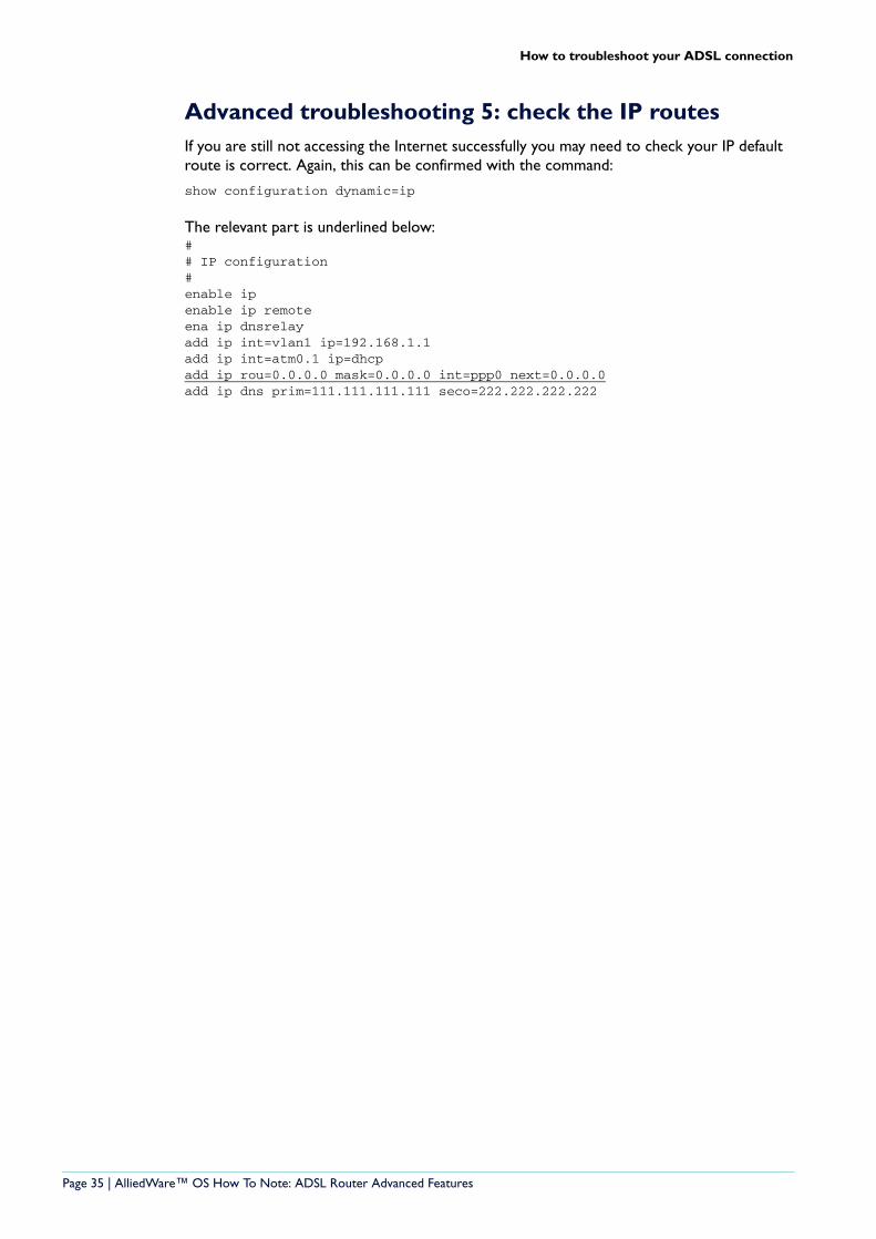
Advanced troubleshooting 5: check the IP routesIf you are still not accessing the Internet successfully you may need to check your IP default route is correct. Again, this can be confirmed with the command:
show configuration dynamic=ip
The relevant part is underlined below:## IP configuration#enable ipenable ip remoteena ip dnsrelayadd ip int=vlan1 ip=192.168.1.1add ip int=atm0.1 ip=dhcpadd ip rou=0.0.0.0 mask=0.0.0.0 int=ppp0 next=0.0.0.0 add ip dns prim=111.111.111.111 seco=222.222.222.222
Page 35 | AlliedWare™ OS How To Note: ADSL Router Advanced Features
Appendix A: Typical ADSL performance figures to expect
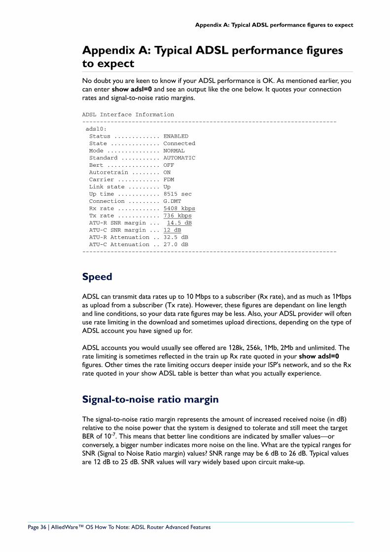
Appendix A: Typical ADSL performance figures to expectNo doubt you are keen to know if your ADSL performance is OK. As mentioned earlier, you can enter show adsl=0 and see an output like the one below. It quotes your connection rates and signal-to-noise ratio margins.
ADSL Interface Information------------------------------------------------------------------------ adsl0: Status ............. ENABLED State .............. Connected Mode ............... NORMAL Standard ........... AUTOMATIC Bert ............... OFF Autoretrain ........ ON Carrier ............ FDM Link state ......... Up Up time ............ 8515 sec Connection ......... G.DMT Rx rate ............ 5408 kbps Tx rate ............ 736 kbps ATU-R SNR margin ... 14.5 dB ATU-C SNR margin ... 12 dB ATU-R Attenuation .. 32.5 dB ATU-C Attenuation .. 27.0 dB------------------------------------------------------------------------
Speed
ADSL can transmit data rates up to 10 Mbps to a subscriber (Rx rate), and as much as 1Mbps as upload from a subscriber (Tx rate). However, these figures are dependant on line length and line conditions, so your data rate figures may be less. Also, your ADSL provider will often use rate limiting in the download and sometimes upload directions, depending on the type of ADSL account you have signed up for.
ADSL accounts you would usually see offered are 128k, 256k, 1Mb, 2Mb and unlimited. The rate limiting is sometimes reflected in the train up Rx rate quoted in your show adsl=0 figures. Other times the rate limiting occurs deeper inside your ISP's network, and so the Rx rate quoted in your show ADSL table is better than what you actually experience.
Signal-to-noise ratio margin
The signal-to-noise ratio margin represents the amount of increased received noise (in dB) relative to the noise power that the system is designed to tolerate and still meet the target BER of 10-7. This means that better line conditions are indicated by smaller values—or conversely, a bigger number indicates more noise on the line. What are the typical ranges for SNR (Signal to Noise Ratio margin) values? SNR range may be 6 dB to 26 dB. Typical values are 12 dB to 25 dB. SNR values will vary widely based upon circuit make-up.
Page 36 | AlliedWare™ OS How To Note: ADSL Router Advanced Features
Appendix B: Checking if your PC is correctly configured
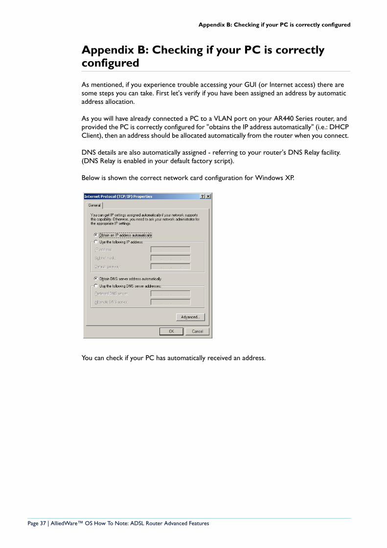
Appendix B: Checking if your PC is correctly configured
As mentioned, if you experience trouble accessing your GUI (or Internet access) there are some steps you can take. First let's verify if you have been assigned an address by automatic address allocation.
As you will have already connected a PC to a VLAN port on your AR440 Series router, and provided the PC is correctly configured for "obtains the IP address automatically" (i.e.: DHCP Client), then an address should be allocated automatically from the router when you connect.
DNS details are also automatically assigned - referring to your router's DNS Relay facility. (DNS Relay is enabled in your default factory script).
Below is shown the correct network card configuration for Windows XP.
You can check if your PC has automatically received an address.
Page 37 | AlliedWare™ OS How To Note: ADSL Router Advanced Features
Appendix B: Checking if your PC is correctly configured
Windows2000 and XP
1. Open the command window (from the Start menu, select Run, then enter “cmd”)
2. Enter the command "ipconfig /all"
3. Check the output. You should see something like the following
Windows 2000 IP Configuration
Host Name . . . . . . . . . . . . : test-pc Primary DNS Suffix . . . . . . . : Node Type . . . . . . . . . . . . : Hybrid IP Routing Enabled. . . . . . . . : No WINS Proxy Enabled. . . . . . . . : No DNS Suffix Search List. . . . . . : alliedtelesis.co.nz
Ethernet adapter Main Lan:
Connection-specific DNS Suffix . : alliedtelesis.co.nz Description . . . . . . . . . . . : Intel(R) PRO/100 VE Network Connection Physical Address. . . . . . . . . : 00-00-39-FD-BB-E5 DHCP Enabled. . . . . . . . . . . : Yes Autoconfiguration Enabled . . . . : Yes IP Address. . . . . . . . . . . . : 10.33.23.35 Subnet Mask . . . . . . . . . . . : 255.255.255.0 Default Gateway . . . . . . . . . : 10.33.23.1 DHCP Server . . . . . . . . . . . : 10.32.16.21 DNS Servers . . . . . . . . . . . : 10.32.16.105 202.49.72.50 Lease Obtained. . . . . . : Wednesday, 10 November 2004 11:15:16 a.m. Lease Expires . . . . . . : Saturday, 20 November 2004 11:15:16 a.m.
Windows 95,98 and ME
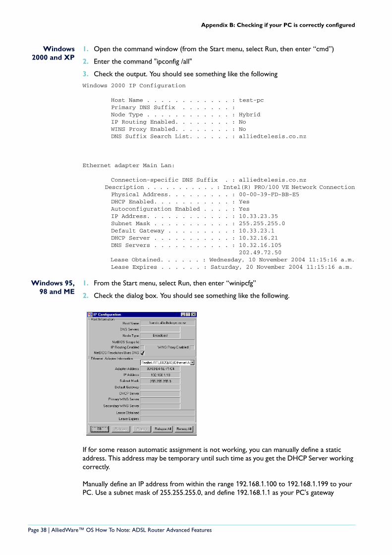
1. From the Start menu, select Run, then enter “winipcfg”
2. Check the dialog box. You should see something like the following.
If for some reason automatic assignment is not working, you can manually define a static address. This address may be temporary until such time as you get the DHCP Server working correctly.
Manually define an IP address from within the range 192.168.1.100 to 192.168.1.199 to your PC. Use a subnet mask of 255.255.255.0, and define 192.168.1.1 as your PC's gateway
Page 38 | AlliedWare™ OS How To Note: ADSL Router Advanced Features
Appendix B: Checking if your PC is correctly configured
address. (This is the router's default factory address). If desired you can also configure your DNS Server address to 192.168.1.1 as the router factory configuration enables DNS Relay.
The procedures below illustrate how to achieve this on various versions of Windows.
Windows2000 and XP
You can manually define an IP address from within the range 192.168.1.100 to 192.168.1.199 to your PC, using Windows 2000/XP.
To achieve this, perform the following steps:
1. Start > Settings > Control panel > Network and Dial-up Connections
2. Open Local Area Network Connections.
3. Click Properties
4. Double Click Internet protocol (TCP/IP)
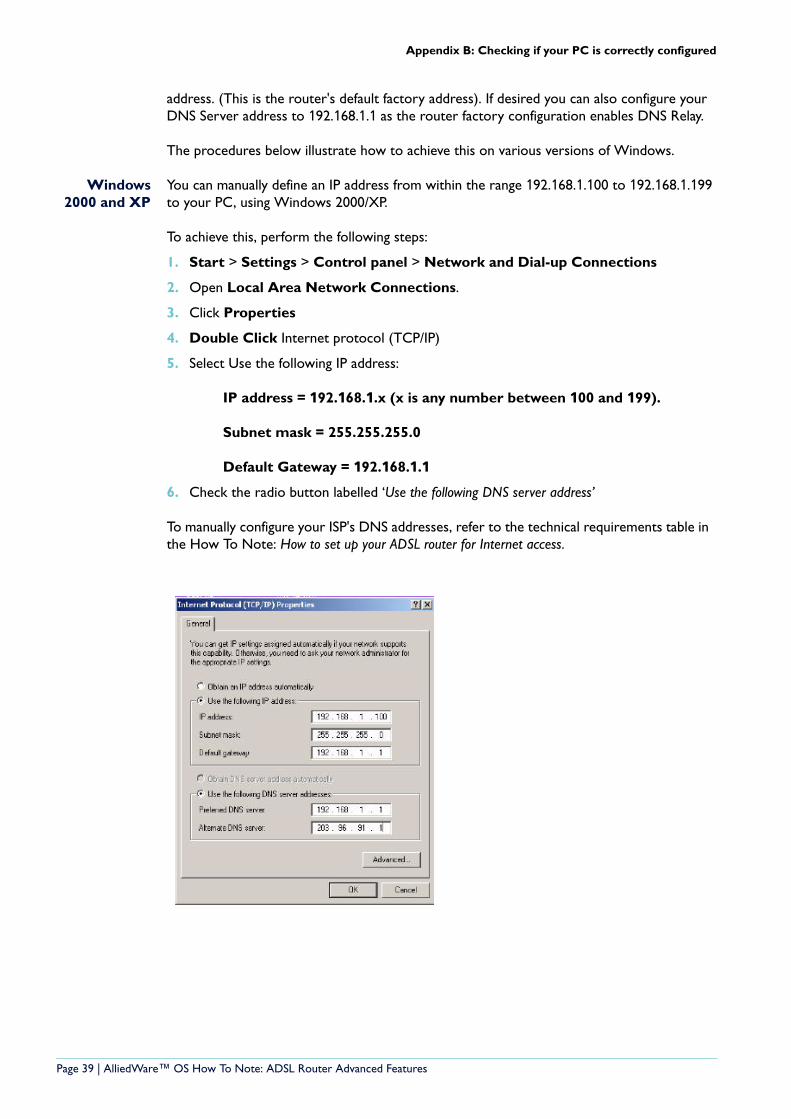
5. Select Use the following IP address:
IP address = 192.168.1.x (x is any number between 100 and 199).
Subnet mask = 255.255.255.0
Default Gateway = 192.168.1.1
6. Check the radio button labelled ‘Use the following DNS server address’
To manually configure your ISP's DNS addresses, refer to the technical requirements table in the How To Note: How to set up your ADSL router for Internet access.
Page 39 | AlliedWare™ OS How To Note: ADSL Router Advanced Features
Appendix B: Checking if your PC is correctly configured
Windows 95,98 and ME
You can manually define an IP address from within the range 192.168.1.100 to 192.168.1.199 to your PC, using Windows 95/98/ME.
To achieve this, perform the following steps:
1. From your Windows desktop right click on the "Network Neighborhood" icon.
2. Select Properties.
3. From the Configuration tab select TCP/IP and click properties.
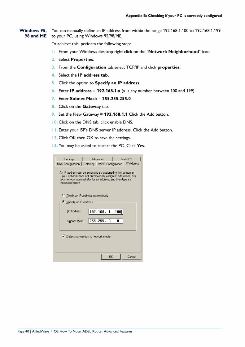
4. Select the IP address tab.
5. Click the option to Specify an IP address.
6. Enter IP address = 192.168.1.x (x is any number between 100 and 199)
7. Enter Subnet Mask = 255.255.255.0
8. Click on the Gateway tab.
9. Set the New Gateway = 192.168.1.1 Click the Add button.
10. Click on the DNS tab, click enable DNS.
11. Enter your ISP's DNS server IP address. Click the Add button.
12. Click OK then OK to save the settings.
13. You may be asked to restart the PC. Click Yes.
Page 40 | AlliedWare™ OS How To Note: ADSL Router Advanced Features