
How is the heat transfer? - جامعة نزوى · PDF fileA shell and tube heat exchanger is...
59
Transcript of How is the heat transfer? - جامعة نزوى · PDF fileA shell and tube heat exchanger is...


How is the heat transfer?
As we discussed early in the first chapter that heat can transfer through materials and the surrounding medium whenever temperature gradient exists until thermal equilibrium is reached.
Heat transfer by:
Radiation is often categorized as either ionizing radiation or non-ionizing radiation depending on the energy of the radiated particles.
Conduction is the transfer of heat through materials by the direct contact of matter.
Convection is the transfer of heat by the motion of the fluid (liquids and gases).
Natural convection
Forced Convection
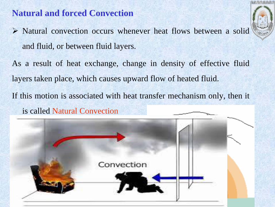
Natural and forced Convection
Natural convection occurs whenever heat flows between a solid
and fluid, or between fluid layers.
As a result of heat exchange, change in density of effective fluid
layers taken place, which causes upward flow of heated fluid.
If this motion is associated with heat transfer mechanism only, then it
is called Natural Convection
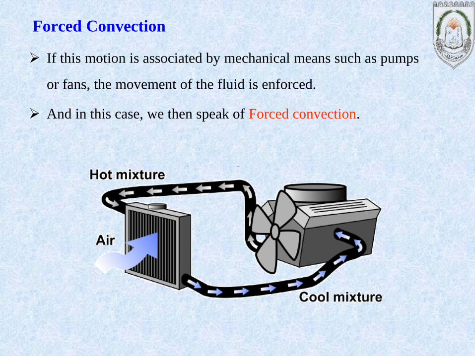
If this motion is associated by mechanical means such as pumps
or fans, the movement of the fluid is enforced.
And in this case, we then speak of Forced convection.
Forced Convection

Types of Heat Exchangers
• Usually involves convection in each fluid and conduction through the
wall of separating the two fluids.
• The overall heat transfer coefficient U contributes to all these factors.
• Usually work with the LMTD.
• LMTD = Logarithmic Mean Temperature Difference
Heat Exchanger is a device that provide the flow of thermal energy
between 2 or more fluids at different temperatures..

They are used in a wide variety of applications. These include power
production process, chemical, food and manufacturing industries,
electronics, environmental engineering, waste heat recovery, air
conditioning, reefer and space applications.
Heat Exchangers may be classified according to the following criteria.
Recuperators/ regenerators
Transfer process: direct and indirect contact
Geometry of construction; tubes, plates, and extended surfaces.
Heat transfer mechanism: single phase and two phase
Flow arrangement: Parallel, counter, cross flow current.
Classification of Heat Exchangers

Transfer process
As mentioned in the previous slight, according to transfer process heat
exchangers are classified as direct contact type and indirect contact type.
In direct contact type, heat is transferred between cold and hot fluids
through direct contact of the fluids (e.g. cooling towers, spray and tray
condensers)
In indirect heat exchanger, heat energy is transferred throw a heat transfer
surface.

Applications of Heat Exchangers
Heat Exchangers
prevent car engine
overheating and
increase efficiency
Heat exchangers are
used in Industry for
heat transfer
Heat exchangers are
used in AC and
furnaces
Heat Exchanger

Basic Principles
Double pipe heat exchanger
Concurrent\Parallel Countercurrent
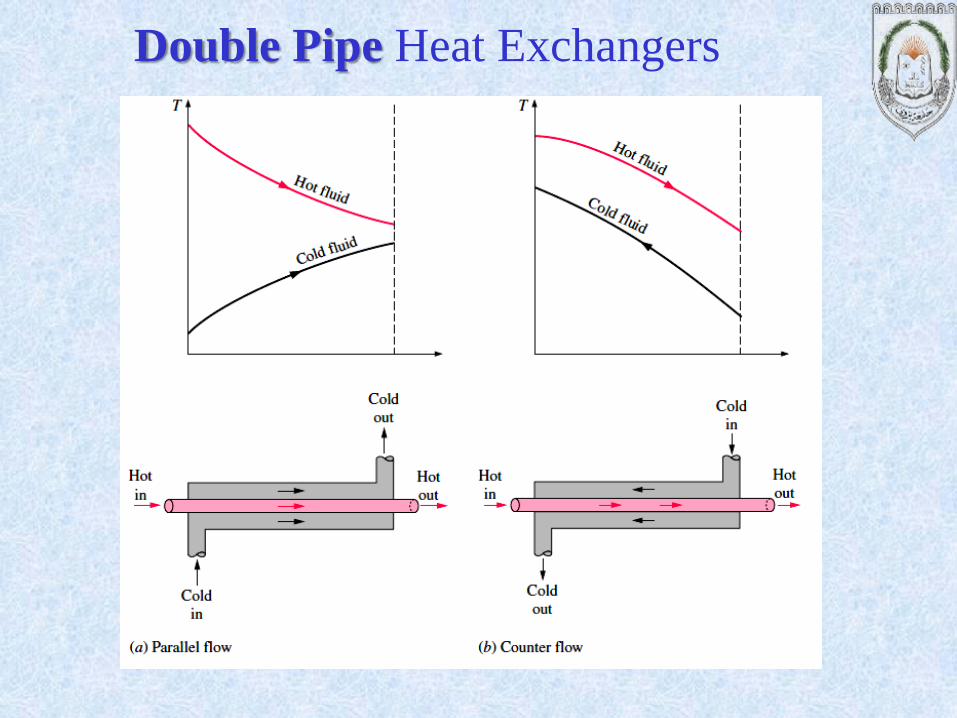
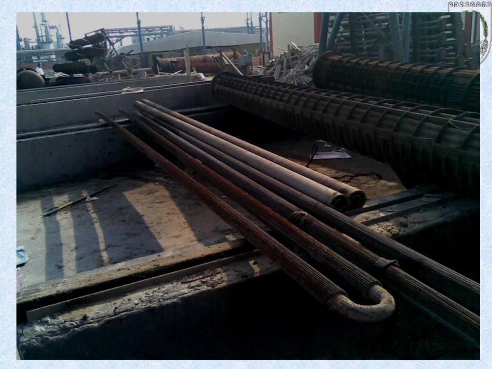
Double Pipe Heat Exchangers

Advantages of Double Pipe Heat Exchanges:
1. Simplest type of heat exchangers
2. Can be easily assembled
3. Relatively low cost
4. Small sizes
Disadvantages of Double Pipe Heat Exchanger:
1. Leakages are very common
2. Requires a lot of time in dismantling and cleaning
3. Small surface area of heat transfer/pipe
4. Space requirements are large
Double pipe heat exchangers should be considered first in design. The
heat transfer surface should not exceed 200 ft2.
If several double pipes are required, their weight increases and thus the
shell and tube heat exchangers is better.


Shell and Tube Heat Exchangers
A shell and tube heat exchanger is a class of heat exchanger designs. It is
the most common type of heat exchanger in oil refineries and other large
chemical processes.
Shell and tube heat exchangers normally consist of a bundle of tubes
fastened into holes, drilled in metal plates called tube sheets.

The Tubular Exchanger Manufacturers Association (TEMA) provides a
manual of standards for construction of shell and tube heat exchangers,
which contains designations for various types of shell and tube heat
exchanger configurations.
The most common types are summarized below.
Shell and Tube Heat Exchangers
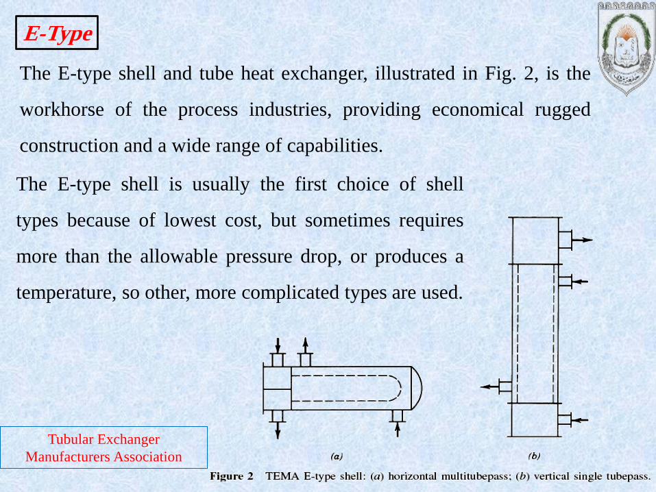
The E-type shell and tube heat exchanger, illustrated in Fig. 2, is the
workhorse of the process industries, providing economical rugged
construction and a wide range of capabilities.
E-Type
The E-type shell is usually the first choice of shell
types because of lowest cost, but sometimes requires
more than the allowable pressure drop, or produces a
temperature, so other, more complicated types are used.
Tubular Exchanger
Manufacturers Association

F-Type
The F-type shell can be effective in some cases if well designed, but has a
number of potential disadvantages, such as :
Thermal and fluid leakage around the longitudinal baffle.
High pressure drop.
Tubular Exchanger
Manufacturers Association
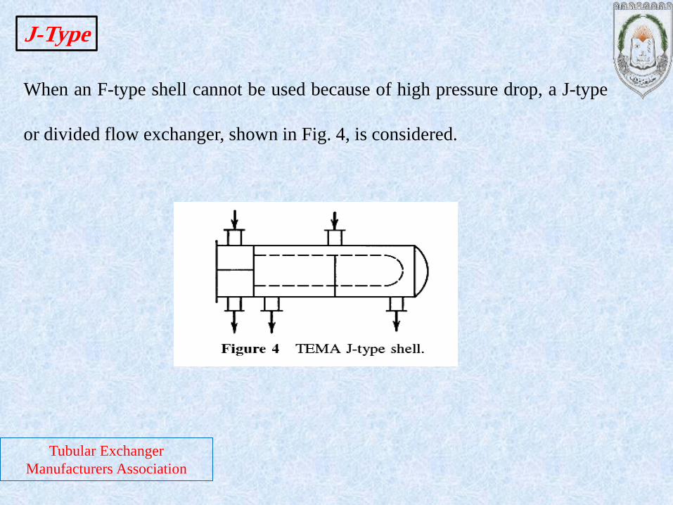
When an F-type shell cannot be used because of high pressure drop, a J-type
or divided flow exchanger, shown in Fig. 4, is considered.
J-Type
Tubular Exchanger
Manufacturers Association

When a J-type shell would still produce too high a pressure drop, an X-type
shell, shown in Fig. 5, may be used.
This type is especially applicable for vacuum condensers, and can be
equipped with integral finned tubes to counteract the effect of low shellside
velocity on heat transfer.
X-Type
Tubular Exchanger
Manufacturers Association

This shell type, shown in Fig. 6, is used especially for boiling range mixtures
and provides better flow distribution than would be the case with the X-type
shell.
The G-type shell also permits a larger temperature cross than the E-type shell
with about the same pressure drop.
G-Type

If a G-type is being considered but pressure drop would be too high, an H-
type may be used. This configuration is essentially just two G-types in
parallel, as shown in Fig. 7.
H-Type

This type is used exclusively for kettle re-boilers and vaporizers, and is
characterized by the oversized shell intended to separate vapor and liquid
phases, Fig. 8.
K-Type

Baffles are used to increase velocity of the fluid
flowing outside the tubes (shellside fluid) and to
support the tubes. Higher velocities have the
advantage of increasing heat transfer and decreasing
fouling (material deposit on the tubes), but have the
disadvantage of more energy consumption.
Baffle-Type
Baffle types commonly used are shown in Fig. 9, with pressure drop
decreasing from Fig. 9a to Fig. 9c.
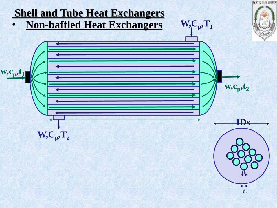
Shell and Tube Heat Exchangers
w,cp,t1
w,cp,t2
• Non-baffled Heat Exchangers W,Cp,T1
W,Cp,T2
IDs
do
di
w,cp,t1
w,cp,t2
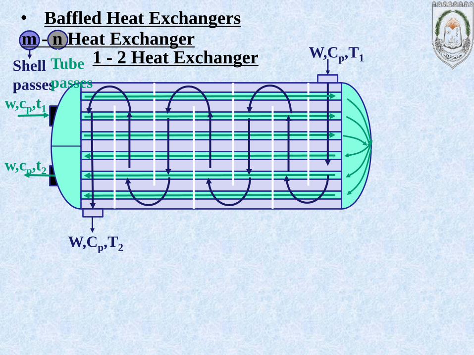
• Baffled Heat Exchangers
W,Cp,T1
W,Cp,T2
Shell
passes
Tube
passes
m - n Heat Exchanger 1 - 2 Heat Exchanger


w,cp,
t1
w,cp,t2
• Baffled Heat Exchangers
W,Cp,
T1
W,Cp,
T2
Shell
passes Tube passes
m - n Heat Exchanger 1 - 2 Heat Exchanger


w,cp,t1 w,cp,t2
• Baffled Heat Exchangers
W,Cp,T1
W,Cp,T2
B
I
D
s
c
1 - 1 Heat Exchanger

Shell-side flow


TEMA Designations
Tubular Exchanger
Manufacturers Association

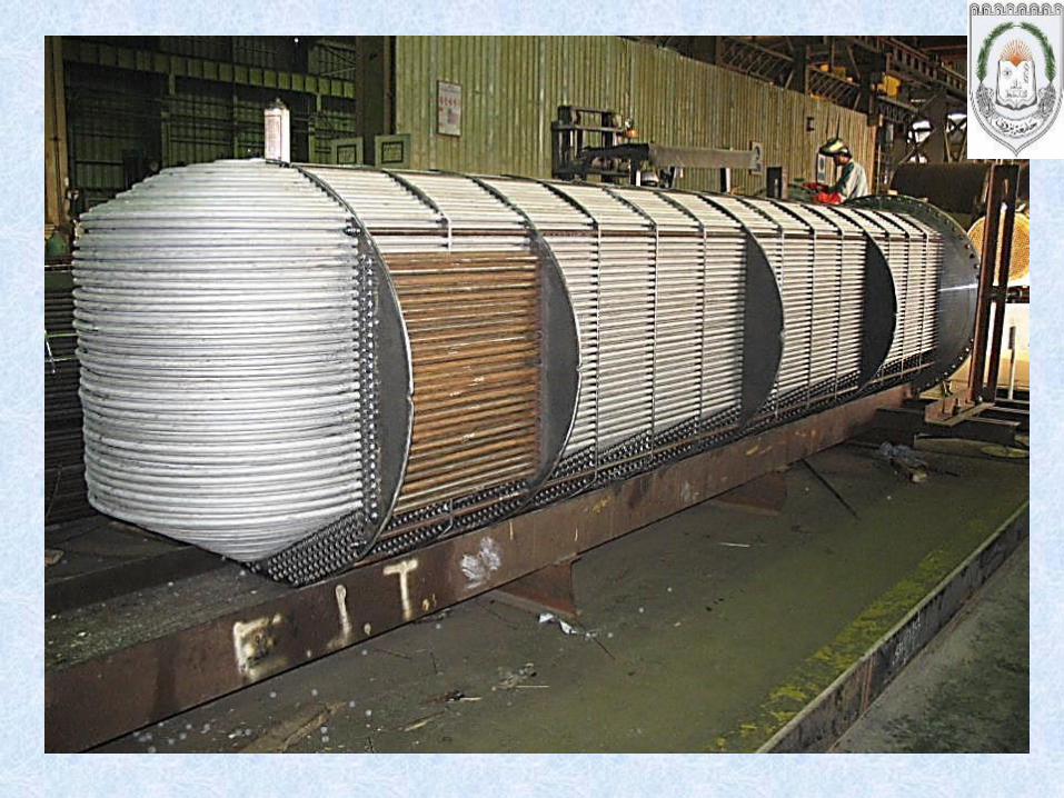
The heat transfer surface consists of a number of thin
corrugated plates pressed out of a high grade metal.
The pressed pattern on each plate surface induces turbulence
and minimizes stagnant areas and fouling.
Unlike shell and tube heat exchangers, which can be custom-
built to meet almost any capacity and operating conditions, the
plates for plate and frame heat exchangers are mass-produced
using expensive dies and presses.
Plate heat exchangers
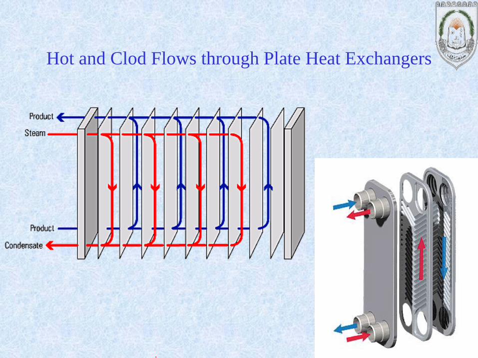
Hot and Clod Flows through Plate Heat Exchangers

Hot and Clod Flows through
Plate Heat Exchangers
Performance of Plate HXs
Superior thermal performance is the hallmark of plate heat exchangers.
Compared to shell-and-tube units, plate heat exchangers offer overall heat
transfer coefficients 3 to 4 times higher.
These values, typically 4000 to 7000 W/m2 ºC (clean), result in very
compact equipment.
This high performance also allows the specification of very small approach
temperature (as low as 2 to 3 ºC) which is sometimes useful in geothermal
applications.
Selection of a plate heat exchanger is a trade-off between U-value (which
influences surface area and hence, capital cost) and pressure drop (which
influences pump head and hence, operating cost).
Classification of Plate HXs
Casketed plate heat exchangers (plate and frame heat
exchangers)
Brazed plate heat exchangers
Welded plate heat exchangers

Gasketed plate heat exchangers
41
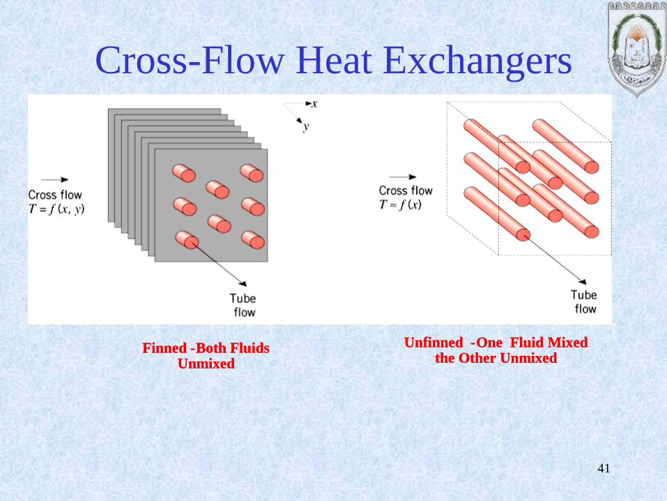
Cross-Flow Heat Exchangers
Finned - Both Fluids Unmixed
Finned - Both Fluids Unmixed
Unfinned - One Fluid Mixed the Other Unmixed
Unfinned - One Fluid Mixed the Other Unmixed
42
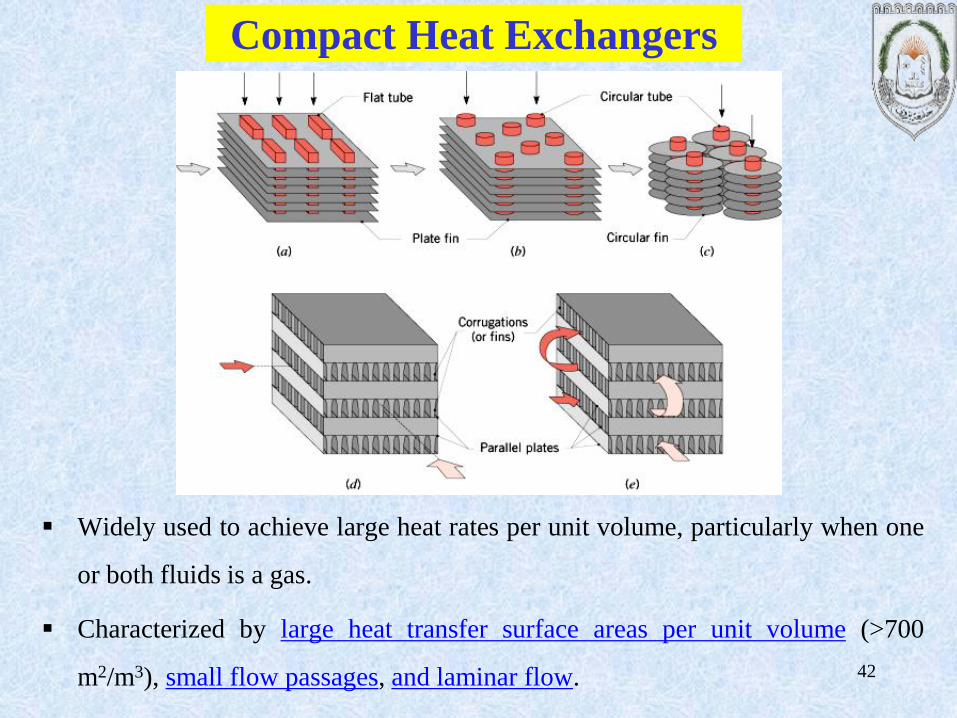
Compact Heat Exchangers
Widely used to achieve large heat rates per unit volume, particularly when one
or both fluids is a gas.
Characterized by large heat transfer surface areas per unit volume (>700
m2/m3), small flow passages, and laminar flow.
Heat Exchangers Chee 318 43

Heat Exchangers Chee 318 44

Baffle Arrangement

Tube sizes
Tubes
Standard tube lengths are 8, 12,
16 and 20 ft.
Tubes are drawn to definite wall
thickness in terms of BWG
(Birmingham Wire Gauge) and
true outside diameter (OD), and
they are available in all common
metals.

The spacing between the tubes
(center to center) is referred to as
the tube pitch (PT). Triangular or
square pitch arrangements are
used. Unless the shell side tends
to foul badly, triangular pitch is
Used.
Tube Pitch

•Heat Exchanger (HEX) Rating
• Checking the existing design for compatibility with the user
requirements (outlet temperature, heat load etc.)
• given: flow rates, inlet temperatures, allowable pressure drop;
thus HT area and passage dimensions.
• find: heat transfer rate, fluid outlet temperatures, actual pressure
drop.
•HEX Sizing
• Thermal and pressure drop considerations, maintenance
scheduling with fouling consideration.
• given: inlet and outlet temperatures, flow rates, pressure drop
• find: dimensions -type and size of HEX. 48

Assumptions for Basic Design Equations for Sizing
• steady-state, steady flow
• no heat generation in the HEX
• negligible ΔPE, ΔKE
• adiabatic processes
• no phase change (later)
• constant specific heats and other physical properties.
49

Overall heat transfer coefficient (U):
Because the temperature difference between the hot
and cold fluid streams varies along the length of the
heat exchanger, it is necessary to derive an average
temperature difference from which heat transfer
calculations can be performed. This average
temperature difference is called the Logarithmic
Mean Temperature Difference (LMTD) ΔTlm.
)/ln( io
iolm
TT
TTT
Where, ΔTo = T1 – T4
ΔTi = T2 – T3

Another way to determine LMTD
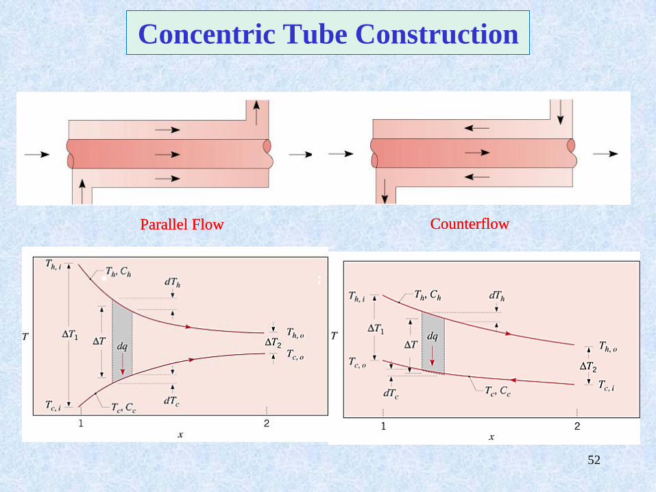
Log Mean Temperature Difference (LMTD) is the heat flows between the hot and cold
streams due to the temperature difference across the tube acting as a driving force. As seen in
the Figure below, the difference will vary with axial position within the HX.
2
1
21
ln
LMTD
Where, θ1 = T1-t2
θ2 = T2-t1
52
Concentric Tube Construction
Parallel Flow CounterflowParallel Flow Counterflow
• : • :
Parallel Flow CounterflowParallel Flow Counterflow

53
Heat Exchanger Analysis LMTD Method
Expression for convection heat transfer for flow of a fluid inside a tube:
)( ,, imompconv TTcmq
lms TAUq )/ln( io
iolm
TT
TTT
U = heat exchanger coefficient, Q = heat transfer rate

In a two-fluid heat exchanger, consider the hot and cold fluids separately:
)(
)(
,,,
,,,
icoccpcc
ohihhphh
TTcmq
TTcmq
lmTUAq and
Need to define U and Tlm
Heat Exchanger Analysis
55
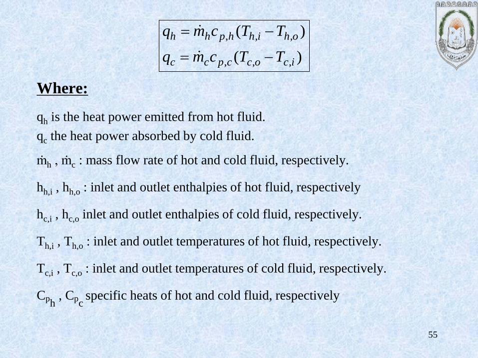
Where:
qh is the heat power emitted from hot fluid.
qc the heat power absorbed by cold fluid.
ṁh , ṁc : mass flow rate of hot and cold fluid, respectively.
hh,i , hh,o : inlet and outlet enthalpies of hot fluid, respectively
hc,i , hc,o inlet and outlet enthalpies of cold fluid, respectively.
Th,i , Th,o : inlet and outlet temperatures of hot fluid, respectively.
Tc,i , Tc,o : inlet and outlet temperatures of cold fluid, respectively.
Cph , Cp
c specific heats of hot and cold fluid, respectively
)(
)(
,,,
,,,
icoccpcc
ohihhphh
TTcmq
TTcmq

With the LMTD method, the task is to select a heat exchanger that will meet the
prescribed heat transfer requirements. The procedure to be followed by the
selection process is:

Example 1