How Do Vestas Manufacture Nacelles - PE Rev3
67
1 How do Vestas manufacture Nacelles
Transcript of How Do Vestas Manufacture Nacelles - PE Rev3

1
How do Vestas manufacture Nacelles
2
V52
V52 – 850 kW – Pitch/Optispeed – 14.00 to 31.40rpm
Weight
Nacelle: ≈22 ton
Rotor: ≈ 10 ton
Sum: ≈ 32 ton
Nacelle factories:
Italy: Taranto V52
Hub factories:
Italy: Taranto V52
_ = Primary factory: Prototype, Working instruction

3
V82
V82 – 1,65 MW – Active-Stall – 14.4 rpm (1 speed generator)
V82 – 1,65 MW(900kW) – Active-Stall – 14.4/10.8 rpm (2 speed generator)
Weight
Nacelle: ≈52 ton
Rotor: ≈ 43 ton
Sum: ≈ 95 ton
Nacelle factories:
Spain: Viveiro V82
India: Chennai V82
Hub factories:
Denmark: Skagen V82
India: Chennai V82
_ = Primary factory: Prototype, Working instruction

4
V80-V90
V80 – 2 MW – Pitch/Optispeed – 9 to 19 rpm
V90 – 1,8-2 MW – Pitch/Optispeed – 9 to 14.9 rpm
V80 – 1,8 MW – Pitch/Optislip – 15.5 to 16.8 rpm
Weight
Nacelle: ≈67 ton
Rotor: ≈ 37 ton
Sum: ≈ 104 ton
Nacelle factories:
Denmark: Viborg V80 2MW
Spain: Leon V80 2MW
China (2007): Tianjin V80 2MW
Hub factories:
Denmark: Ringkøbing V80 2MW
China (2007): Tianjin V80 2MW
_ = Primary factory: Prototype, Working instruction

5
V90
V90 – 3 MW – Pitch/Optispeed – 8.6 to 18.4 rpm
Weight
Nacelle: ≈70 ton
Rotor: ≈ 41 ton
Sum: ≈ 111 ton
Nacelle factories:
Denmark: Ringkøbing V90 3MW,
Hub factories:
Denmark: Ringkøbing V90 3MW,
_ = Primary factory: Prototype, Working instruction
6
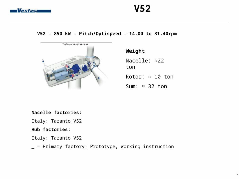
Nacelles Value Chain
Foundries Machining
Generators
Vestas Nacelles Value Chain
Assembly and test

7
Vestas Nacelles production facilities
Denmark, Norway, Sweden, Germany, Italy, Spain, India and China

8
Vestas Castings
Vestas Castings:Magdeburg, components up to 11 tonKristianssand, components up to 20 tonsGuldsmedshyttan components up to 40 ton

9
Vestas Machining - Lem
•Ca. 20,100 m2

10
Vestas Generator - Lübeck

11
Pictures from Ringkøbing

12
Pictures from LeonViveiro
V82
LeònV90 2MW

13
Pictures from Viveiro

14
Pictures from Taranto

15
Pictures from Chennai
16
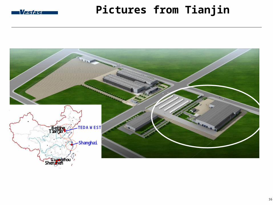
Pictures from Tianjin
BeijingTianjin
Shanghai
GuangzhouShenzhen
TEDA WEST

17
Pictures from Tianjin
Land approx. 50.000 sqm
Buildings approx. 13.000 sqm.

18
Pictures from Viborg (1)

19
Factory Viborg
Operation 0100Main foundation Yaw beamYaw gear
Operation 0200Crane column
Operation 0300GearMain shaft/bearingHydraulic station
Operation 0700Assembling of main foundation and rearCrane finish Cables
Operation 0800Final test
Operation 0900Glass fiber cabinReady for shipment
Operation 0400Rear sectionGenerator
Operation 0500Control cabinetTransformer
Operation 0600CablesGenerator finish
Front
Rear
LEAN-Production in Viborg (15-18 turbines/week):
6 step (2x3 parallel + 3) 1 step takes 6 hours. Target is 4 hours

20
Pictures from Viborg (2)

21
Pictures from Viborg (3)

22
Pictures from Viborg (4)

23
Pictures from Viborg (5)

24
Pictures from Viborg (6)

25
Pictures from Viborg (7)

26
Pictures from Viborg (8)

27
Pictures from Viborg (9)

28
Pictures from Viborg (10)

29
Pictures from Viborg (11)

30
Pictures from Viborg (12)

31
Pictures from Viborg (13)

32
Pictures from Viborg (14)

33
Pictures from Viborg (15)

34
Pictures from Skagen (1)

35
Pictures from Skagen (2)

36
Pictures from Skagen (3)

37
Responsibility
38
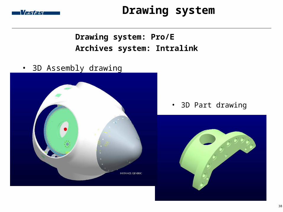
Drawing system
Drawing system: Pro/EArchives system: Intralink
• 3D Assembly drawing
• 3D Part drawing

39
Drawing system
• Assembly drawing
• Production drawings

40
Structure
Level 1 (Nacelle)
Level 2 (Main module)
Level 3 (Sub module)
Level 4-x (Assembly)
Main foundation mod
Rear foundation mod
Generator mounted
Generator module
Slip-ring module
Yaw module
Nacelle cover module
Mainshaft-gear mod.
Mainshaft module
Gearbox brake offl.filt.
Rotating transfer mod.
Torquearm module
Torquearm left
Torquearm right
V80 - 76 Variants:V80/V90, 50 Hz/60Hz, Ral 7035/9010, VCS/VRCC etc.

41
Certificate
A turbine can’t be erected without a certificate.Certificates can be issued by GL, DNV and TÜV based on documentation from Vestas. Guidelines and standards: IEC 61400, DS 472, NVN 11400, GL, DIBt etc.
Three elements in the certificate: - Design assessment. Verification of the design and engineering documents. Turbine management and safety. Load calculation.Strength calculation.
- Quality management ISO 9001 covers the majority of the requirements .
- Prototype testValidation of the calculations.Turbine management.Performance.Noise.Grid compatibility.

42
Operational Loads
Wind Loads etc. (Flex5)Gravity (9,82 N/kg)Horizontal acceleration - Extreme: ≈5 N/kg – Fatigue: ≈1 N/kg (m=5, n=10^7)
Loads based on GL category 1A Extreme wind speed for 80 m V = 70 m/sAnnual average for 80 m V = 10 m/sTurbulence intensity for category A1 = 18 %
(3. december 1999 51,4 m/s)(“Katrina Hurricane” 2005 77,8 m/s)
Extreme moment at blade flange V80: ≈6000kNm = 1000kg at 600m

43
Transport Loads
-Transport

44
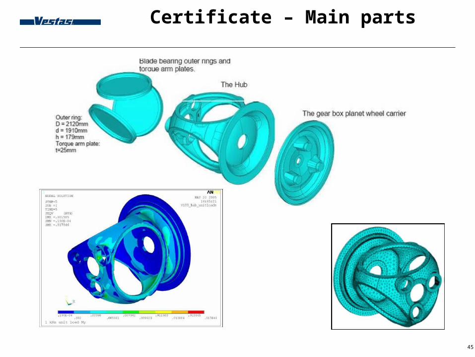
Certificate – Main parts
Component Approval Issue
Hub Loads: Flex 5Strength: FEM
Fatigue and static strengthDeformations by the bearings.
Machine frame Loads: Flex 5Strength: FEM
Fatigue and static strength
Rear section Loads: Flex5 + AnalyticStrength: Analytic + FEM
Fatigue and static strengthWelded component
Drive train Loads: Flex5 + AnalyticStrength: FEM
Fatigue and static strengthWelded component
Crane with traverse
Loads: AnalyticStrength: Analytic + FEM
Static strengthWelded component
45
Certificate – Main parts

46
Certifikate – Small parts
Component Approval Issue
Bearings Loads: Flex 5Strength: Approved by supplier
Fatigue and static strength
Main bearing housing
Loads: Flex 5Strength: FEM
Fatigue and static strength
Rotor lock Loads: Flex 5Strength: Approved by supplier
Static strength
Coupling and breake
Loads: Flex 5Strength: FEM / Supplier
Fatigue and static strength
Gear box torque arms
Loads: Flex 5Strength: FEM / Supplier
Fatigue and static strength

47
The rest
• ≈ 1000 drawings of different parts for one Turbine
For example:
Tread platesGlass fiber cabinet/nose cone supportSupport for hydraulic and electrical partsCoolersLaddersAnemometerCover platesHatchesEtc.

48
Standards - Why?
The components shall be produced global without problems.Knowledge to standards and GPS (Geometrical product specification) is therefore important
Chinese supplier

49
Design - PE
Add standards:
Not add better requirements than necessary!
Not all requirements are mentioned on the drawings. Remember to check the bill of material in INFOR

50
Design - PE
Drawing head - assembling:
Bulk items in the BOM: Georoil etc:
Accessories not separate in the BOM: Cable Stripper, lock oil etc

51
Design - PE
Verdana 12 pt, font colour white
Drawing head - part:
52
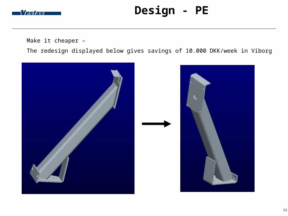
Design - PE
Verdana 12 pt, font colour white
Make it cheaper –
The redesign displayed below gives savings of 10.000 DKK/week in Viborg
53
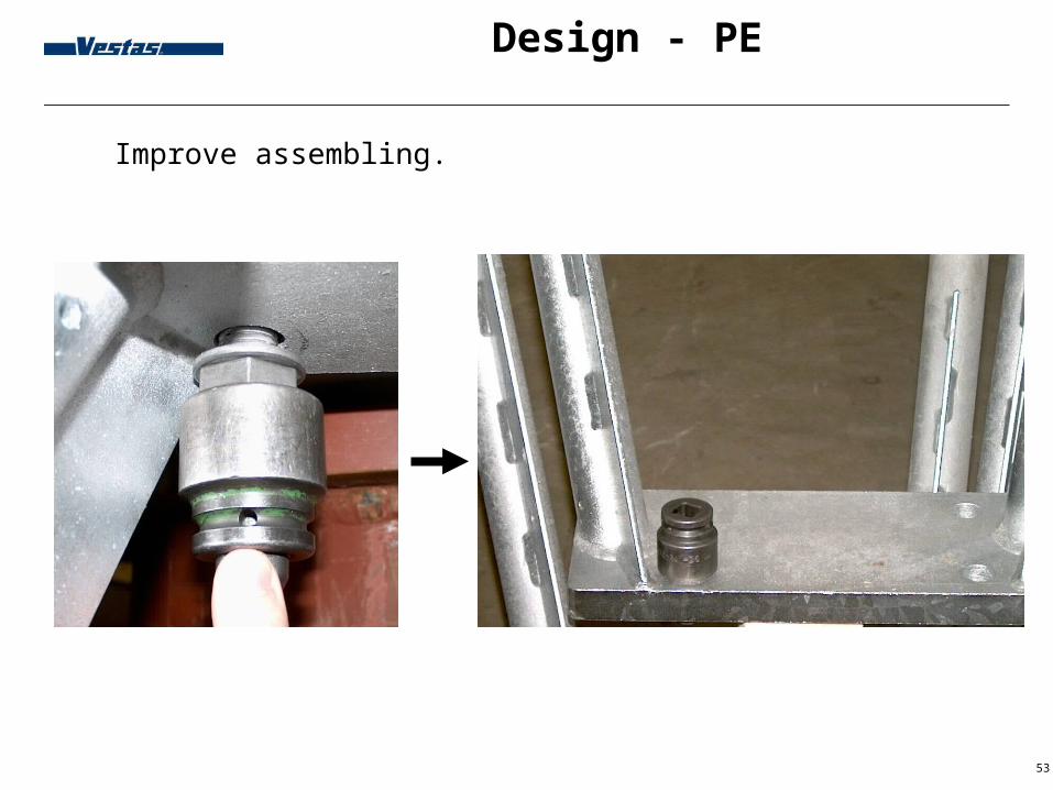
Design - PE
Improve assembling.
54
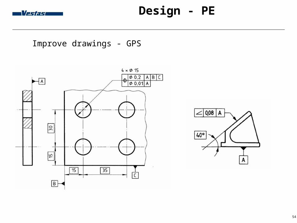
Design - PE
Improve drawings - GPS

55
Design - PE
Improve drawings – GPS – 3D measuring (Tolerance 0,003)

56
Design - PE
Improve drawings – GPS Lasertracker

57
Design - PE
Verdana 12 pt, font colour white
See failures before they occur
Fatigue crack
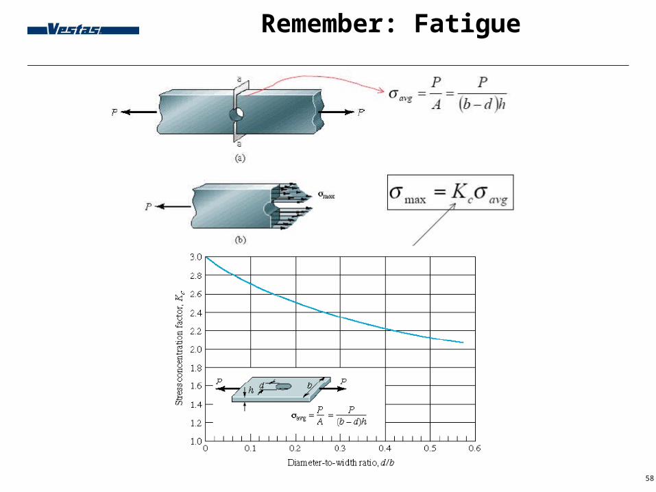
58
Remember: Fatigue
Verdana 12 pt, font colour white

59
Remember: Fatigue

60
NCR - PE
BP 04.03.00.This procedure is valid for the handling of non-conformity items/products detected during Vestas' manufacturing, storage, transport, installation and commission activities until the after sales system/procedures takes over.

61
NCR - PE

62
Surface treatment
Verdana 12 pt, font colour white
Inside Nacelle: C3Hot dip galvanizing acc. ISO 1461:1999 minimum local thickness 45 µm Thermal spraying acc. ISO 2063:2005 (ISO 14919:2001 ZnAl15) 70 µm Thermal spraying acc. ISO 2063:2005 (ISO 14929:2001 ZnAl 15) 50 + S3.17
Indvendig Inside Hub: C4Hot dip galvanizing acc. ISO 1461:1999 minimum local thickness 85 µm Thermal spraying acc. ISO 2063:2005 (ISO 14919:2001 ZnAl15) 110 µm Thermal spraying acc. ISO 2063:2005 (ISO 14929:2001 ZnAl 15) 100 + S4.20
Outside Nacelle: C5MHot dip galvanizing acc. ISO 1461:1999 minimum local thickness 170 µm Thermal spraying acc. ISO 2063:2005 (ISO 14929:2001 ZnAl 15) 100 + S7.02

63
Documentation
Documentation demand, see BP 08.16.00 Work instruction, Purchase specification, Quality Specification, Control instruction, Inspection scheme, Supplier approval
A-item are items where defects affect theQuality of the product, Environment, SafetyAssuranceLegislation prescribes calculations, safety evaluations, production documentation
B-item are items (including catalogue items), that defects only marginally affect the Product quality, EnvironmentSafety The defect will be detected in the prescribed inspections Only capable of affecting processes and reliability of supply briefly. Items not classified as A-item, which are designed by Vestas and must be purchased, are classified as B-items.
U-item are items where defect not affectsEnvironmentProduction qualityDefects and lacks will bee corrected before use.

64
Material - Welding - Cast
Quality requirements - WeldingDepending on consequence and use (Loads etc). See nacelle notes guideline
QS 993667 (Elementary quality requirements)QS 993665 (Comprehensive quality requirements)
If there is a reference to TPS 901529 or TPS 901530 it is allowed to manufacture the item in an substitute material for example Chinese standardized steel.
TPS 901528: Casting quality requirements
TPS 901529: Parts - Certified components (Approved by DNV, GL etc.) / Component which are important for the safety of the turbineThe substitute material has at least the same strength as the specified material.
TPS 901530: Parts - Non certified components / Non-important components. The substitute material may be weaker than the specified strength of the parent material:Strength of steel S355 (EN 10025) may be reduced with max. 10%Strength of steel S235 (EN 10025) may be reduced with max. 5%Strength of stain less steel is min. 150 MPaStrength of aluminium may be reduced with max. 20%Strength of other materials may be reduced with max. 10%

65
Temperature
Production stop:Alarm 19: Ambient temperature too low : -30 °CAlarm 83: Gear oil temperature too low : -10 °CAlarm 94: Nacelle temperature too low : -15 °C

66
Tower

67
Local content percentage distribution
on componentsName of component NDRC
[%]Possible NDRC [%]
Tower 16.9 9.0
Electrics in Wind Farm 7.2
Nacelle cover 4.4 4,0
Generator 7.4 8.0
Blade 22.5 19.0
Gearbox 15.4 15.0
Main shaft, (incl. Bearings, coupling) 3.4 4.0
Hub (incl. Pitch regulated system) 4.2 7.0
Yaw system 1.3 5.0
Central control and monitoring system 3.5 3.0
Electrical control sys. (SCADA) incl. inverter 3.5 16.0
Hydraulic system 2.2 2.0
General assembly 3.0 3.0
Spareparts 1.0 5.0
Others 4.1
SUM 100.0 100.0