Hovering by Gazing: A Novel Strategy for Implementing ... · Hovering by Gazing: A Novel Strategy...
14
Hovering by Gazing: A Novel Strategy for Implementing Saccadic Flight-based Navigation in GPS-denied Environments Augustin Manecy, Nicolas Marchand, St´ ephane Viollet To cite this version: Augustin Manecy, Nicolas Marchand, St´ ephane Viollet. Hovering by Gazing: A Novel Strategy for Implementing Saccadic Flight-based Navigation in GPS-denied Environments. International Journal of Advanced Robotic Systems, InTech, 2014, 11 (66), 13 p. <10.5772/58429>. <hal- 00982329> HAL Id: hal-00982329 https://hal.archives-ouvertes.fr/hal-00982329 Submitted on 23 Apr 2014 HAL is a multi-disciplinary open access archive for the deposit and dissemination of sci- entific research documents, whether they are pub- lished or not. The documents may come from teaching and research institutions in France or abroad, or from public or private research centers. L’archive ouverte pluridisciplinaire HAL, est destin´ ee au d´ epˆ ot et ` a la diffusion de documents scientifiques de niveau recherche, publi´ es ou non, ´ emanant des ´ etablissements d’enseignement et de recherche fran¸cais ou ´ etrangers, des laboratoires publics ou priv´ es.
Transcript of Hovering by Gazing: A Novel Strategy for Implementing ... · Hovering by Gazing: A Novel Strategy...
Hovering by Gazing: A Novel Strategy for Implementing
Saccadic Flight-based Navigation in GPS-denied
Environments
Augustin Manecy, Nicolas Marchand, Stephane Viollet
To cite this version:
Augustin Manecy, Nicolas Marchand, Stephane Viollet. Hovering by Gazing: A Novel Strategyfor Implementing Saccadic Flight-based Navigation in GPS-denied Environments. InternationalJournal of Advanced Robotic Systems, InTech, 2014, 11 (66), 13 p. <10.5772/58429>. <hal-00982329>
HAL Id: hal-00982329
https://hal.archives-ouvertes.fr/hal-00982329
Submitted on 23 Apr 2014
HAL is a multi-disciplinary open accessarchive for the deposit and dissemination of sci-entific research documents, whether they are pub-lished or not. The documents may come fromteaching and research institutions in France orabroad, or from public or private research centers.
L’archive ouverte pluridisciplinaire HAL, estdestinee au depot et a la diffusion de documentsscientifiques de niveau recherche, publies ou non,emanant des etablissements d’enseignement et derecherche francais ou etrangers, des laboratoirespublics ou prives.
Hovering by Gazing: a NovelStrategy for Implementing SaccadicFlight-based Navigation inGPS-denied Environments
immediate⋆
Abstract Hovering flies are able to stay still in placewhen hovering above flowers and burst into movementtowards a new object of interest (a target). This suggeststhat sensorimotor control loops implemented onboardcould be usefully mimicked for controlling UnmannedAerial Vehicles (UAVs). In this study, the fundamentalhead-body movements occurring in free-flying insectswas simulated in a sighted twin-engine robot with amechanical decoupling inserted between its eye (or gaze)and its body. The robot based on this gaze control systemachieved robust and accurate hovering performances,without an accelerometer, over a ground target despite anarrow eye field of view (±5). The gaze stabilizationstrategy validated under Processor-In-the-Loop (PIL) andinspired by three biological Oculomotor Reflexes (ORs)enables the aerial robot to lock its gaze onto a fixed targetregardless of its roll angle. In addition, the gaze controlmechanism allows the robot to perform short range targetto target navigation by triggering an automatic fast "targetjump" behaviour based on a saccadic eye movement.
Keywords Micro Aerial Vehicle, Automatic Navigation,Gaze Control, Visual Control, Hover Flight, EyeMovement, Oculomotor Control, Biorobotics
Acronyms
FOV: Field Of View.
rVOR: Rotational Vestibulo-Ocular Reflex.
tVOR: Translational Vestibulo-Ocular Reflex.
VFR: Visual Fixation Reflex.
ZSL: Zero-Setting System.
VFL: Visual Feedback Loop.
D-EYE: Decoupled eye robot.
F-EYE: Fixed eye robot.
PIL: Processor-In-the-Loop.
MLD: Maximum Lateral Disturbance.
1. Introduction
Making Unmanned Aerial Vehicles (UAVs) autonomousis likely to be a key research subject for the next 10years. To achieve this autonomy, one of the mostcrucial steps is stabilizing the attitude of aerial vehicles.This objective has been classically achieved using anInertial Measurement Unit (IMU) composed of rate gyros,accelerometers and magnetometers ([1–3]).But IMUs oftenhave to be combined with other sensors to estimate theposition of the UAV without drifts. A GPS has been used,
Augustin Manecy, Nicolas Marchand and Stéphane Viollet: Hovering by Gazing:
A Novel Strategy for Implementing Saccadic Flight-based Navigation in GPS-denied Environments
1
ARTICLE
Int J Adv Robot Syst, 2014, 11:66 | doi: 10.5772/58429
1 University Grenoble Alpes, CNRS, GIPSA-Lab, F-38000 Grenoble, France2 Aix-Marseille University, CNRS, ISM UMR 7287, Marseille, France3 CNRS, France* Corresponding author E-mail: [email protected]
Received 25 Sep 2013; Accepted 02 Mar 2014
DOI: 10.5772/58429
∂ 2014 The Author(s). Licensee InTech. This is an open access article distributed under the terms of the CreativeCommons Attribution License (http://creativecommons.org/licenses/by/3.0), which permits unrestricted use,distribution, and reproduction in any medium, provided the original work is properly cited.
Augustin Manecy1,2,3,*, Nicolas Marchand1,3 and Stéphane Viollet2,3
Hovering by Gazing: A Novel Strategy for Implementing Saccadic Flight-based Navigation in GPS-denied EnvironmentsRegular Paper
International Journal of Advanced Robotic Systems
for example, to remove the bias from the pose estimatesin outdoor applications ([4–6]). Many strategies involvingvision and IMU combined have been adopted for indoorapplications because they work efficiently in GPS-deniedenvironments. For example, [7] used an external trajectorydevice yielding very fast dynamics, which was able toaccurately measure both the position and the attitude of arobot equipped with markers. Likewise, [8] used a simpleexternal CCD camera to measure the positions of two LEDmarkers onboard a quadrotor. Although external visualsensing devices of this kind are quite accurate, their visualcomputational resources often have to be provided by aground-based host computer. In other studies, the visualsensor was implemented onboard a robot, which wasstabilized using two elliptic markers (one placed underthe robot and the other in front of it) to determine itsattitude and position ([9]). Five markers with a specificgeometry were used by [10] to estimate the robot’s yawand position, while an IMU gave the robot’s attitude andangular velocities. Another particularly cheap solution([11]) comprised using a Wii remote sensor (Nintendo) tocontrol a hovering vehicle, while the pitch and roll weremeasured by an IMU. Another solution ([12]) consisted ofmerging a five DOF estimation provided by a monocularcamera with a gravity vector estimation provided byan IMU to achieve take-off, hovering and landing of aquadrotor. Successful control of a hovering quadrotorwas achieved by cancelling the linear velocity based onoptic flow measurements ([13], [14]). Optic flow was alsoused to estimate the altitude and the forward speed of anairborne vehicle ([15]). The robot’s attitude has usuallybeen determined in these studies by means of an IMUcombined with accelerometers compensating for the drift.However, the authors of several studies have used smallor panoramic cameras to determine the robot’s attitude([7]). Visual servoing was recently applied to stabilize ahovering quadrotor equipped with a fixed camera facinga ground-coloured target ([16]). When this approach wastested under natural outdoor conditions, its vision-basedhovering accuracy was found to range between -2m and2m. In [17], a monocular camera and computer visionwith high delays was used to avoid drift obtained with asimple IMU pose estimation. A camera is also used in [18]as a dual-sensor to achieve a drift-free hover and performobstacles avoidance on a quadrotor.
In our bio-inspired minimalistic framework, a new controlstrategy was developed, which consists of using only threesensors:• an optical angular position sensing device with a small
Field-Of-View (FOV) of only a few degrees, which isable to locate the angular position of a ground targetwith great accuracy ([19], [20])
• a low-cost rate gyro• a simple proprioceptive sensor used to measure the eye
orientation in the robot’s frame.
Using a decoupled eye onboard an UAV greatly reducesthe computational complexity because a narrower FOVcould be used, meaning fewer pixels were needed. In aprevious robotic study ([21]), a decoupled eye is classicallyused as an observation device to track a target andcompensate for the UAV displacements around this target.
The latter was successfully tracked by an autonomoushelicopter, the position and attitude of which weredetermined using a combination of GPS and IMU. In thepresent study, it was proposed to use the robot’s own gaze(i.e., the orientation of the eye in the inertial frame) asa reference value in order to determine its rotations andpositions.
An eye with a restricted FOV of only a few degrees (likea kind of fovea1) was adopted here for the following mainreasons:• a small FOV means that very few pixels have to be
processed because a small FOV can be obtained byselecting a small Region Of Interest (ROI)
• a small ROI means a high frame rate• a fovea makes it possible to greatly reduce the
computational complexity of the visual processingalgorithms, as described in [22]. Therefore that tiny,low-cost, low consumption microcontroller can beimplemented onboard the robot.
The robot’s eye was taken to be a visual Position-SensingDevice (PSD), which is able to locate an edge (or a bar)accurately thanks to its small FOV (here, FOV = ±5°,in opposition to a classical FOV of ±25°). This visualsensor was endowed with hyperacuity ([23]), i.e., theability to locate a contrasting target with a much betterresolution than that dictated by the pixel pitch. Theimplementation of this kind of hyperacute sensor visualsensor was described by previous authors ([19, 20, 24–26]).
The simulated robot and its decoupled eye are describedin section 2 along with the nonlinear dynamic model. TheProcessor-In-the-Loop (PIL) system used to perform thesimulations was also described in this section. The originalnonlinear observer presented in section 3 estimates thelinear speed, the position, the attitude (on the roll axis onlyin this paper), and the rate gyro’s bias. Then the gazecontroller as well as the whole robot controller based onthese estimations is described in detail. In section 4, a newnavigation strategy for aerial robots in terms of automatictarget to target navigation based on a saccadic flight isoutlined. Lastly, the advantages of using a decoupledeye with a gaze control strategy are discussed before theconclusion.
2. System overview
In this part, we will describe first the PIL system andthe custom toolchain we developed to perform the robot’ssimulation. Then we will present how the biology hasinspired our approach and finally we will present thetwin-engine robot’s model.
2.1 Processor-In-the-Loop (PIL) simulation
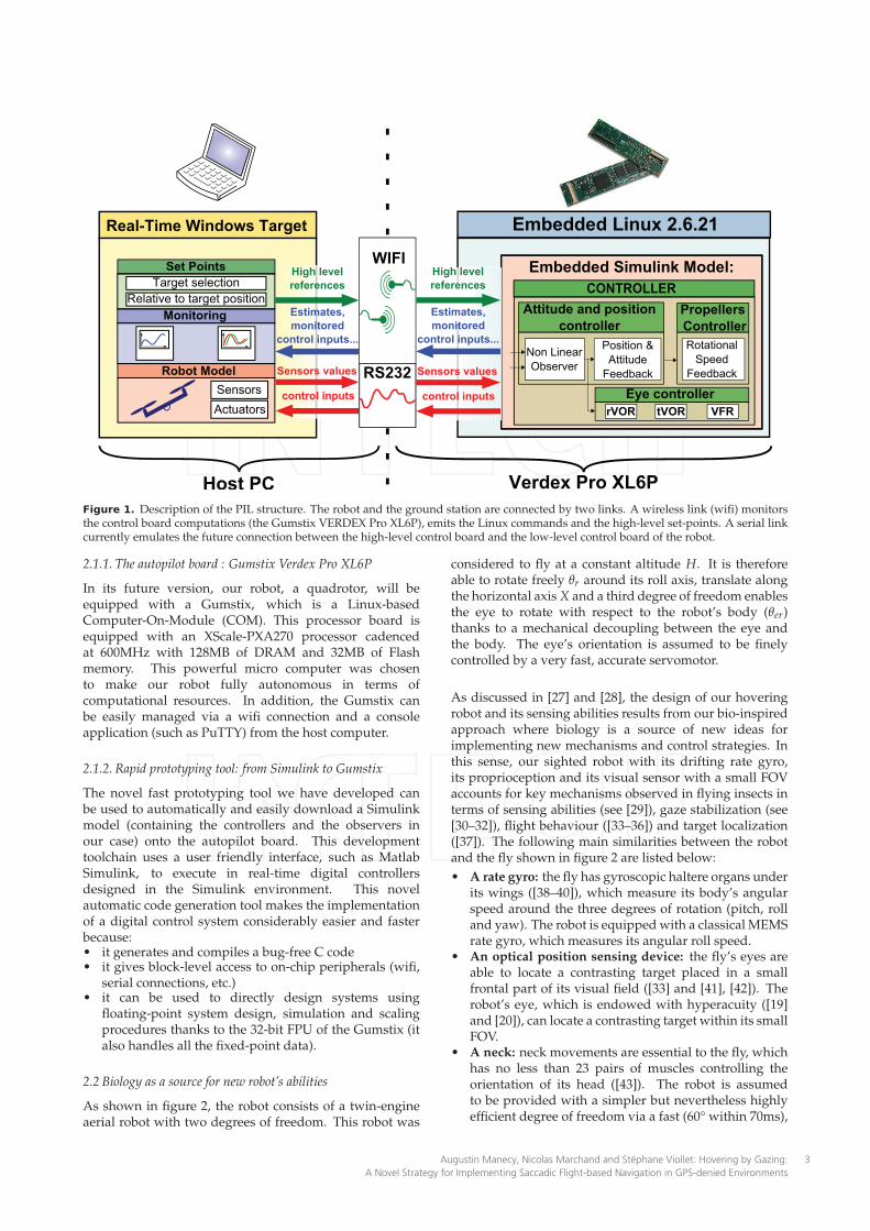
All the simulations presented in this study wereperformed using an Processor-In-the-Loop (PIL) system.Figure 1 shows the environment and the links existingbetween the host computer and the embedded processorboard. The host computer simulates the robot’s dynamicsin real time and monitors the computations performed bythe embedded autopilot board which controls the robot.
1 The fovea is a part of the eye which is responsible for sharp central vision,useful where visual detail is of primary importance.
Int J Adv Robot Syst, 2014, 11:66 | doi: 10.5772/584292
Embedded Simulink Model:
Monitoring
Robot Model
Set Points
Host PC
Estimates,
monitored
control inputs...
Sensors values
High level
references
Verdex Pro XL6P
Target selection
Relative to target position
Sensors
Actuators
RS232
WIFI
Estimates,
monitored
control inputs...
High level
references
Embedded Linux 2.6.21Real-Time Windows Target
CONTROLLER
Non Linear
Observer
Propellers
Controller
Position &
Attitude
Feedback
Attitude and position
controller
Eye controller
Rotational
Speed
Feedback
rVOR tVOR VFR
control inputs
Sensors values
control inputs
Figure 1. Description of the PIL structure. The robot and the ground station are connected by two links. A wireless link (wifi) monitorsthe control board computations (the Gumstix VERDEX Pro XL6P), emits the Linux commands and the high-level set-points. A serial linkcurrently emulates the future connection between the high-level control board and the low-level control board of the robot.
2.1.1. The autopilot board : Gumstix Verdex Pro XL6P
In its future version, our robot, a quadrotor, will beequipped with a Gumstix, which is a Linux-basedComputer-On-Module (COM). This processor board isequipped with an XScale-PXA270 processor cadencedat 600MHz with 128MB of DRAM and 32MB of Flashmemory. This powerful micro computer was chosento make our robot fully autonomous in terms ofcomputational resources. In addition, the Gumstix canbe easily managed via a wifi connection and a consoleapplication (such as PuTTY) from the host computer.
2.1.2. Rapid prototyping tool: from Simulink to Gumstix
The novel fast prototyping tool we have developed canbe used to automatically and easily download a Simulinkmodel (containing the controllers and the observers inour case) onto the autopilot board. This developmenttoolchain uses a user friendly interface, such as MatlabSimulink, to execute in real-time digital controllersdesigned in the Simulink environment. This novelautomatic code generation tool makes the implementationof a digital control system considerably easier and fasterbecause:• it generates and compiles a bug-free C code• it gives block-level access to on-chip peripherals (wifi,
serial connections, etc.)• it can be used to directly design systems using
floating-point system design, simulation and scalingprocedures thanks to the 32-bit FPU of the Gumstix (italso handles all the fixed-point data).
2.2 Biology as a source for new robot’s abilities
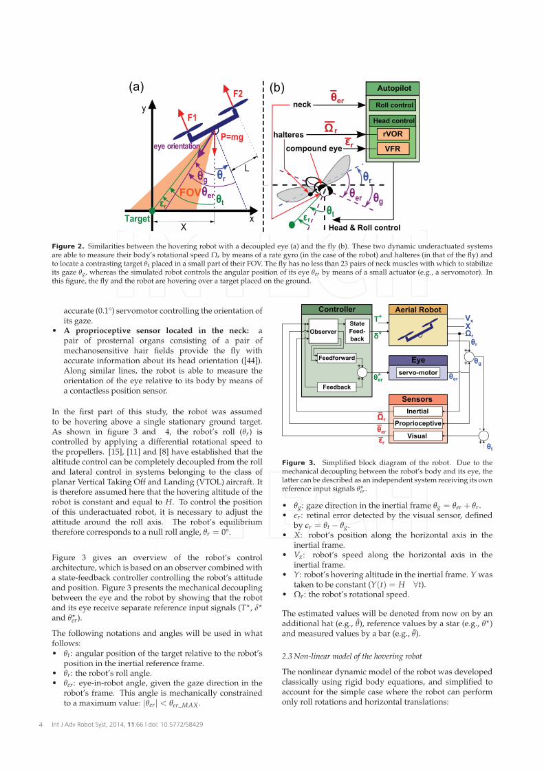
As shown in figure 2, the robot consists of a twin-engineaerial robot with two degrees of freedom. This robot was
considered to fly at a constant altitude H. It is thereforeable to rotate freely θr around its roll axis, translate alongthe horizontal axis X and a third degree of freedom enablesthe eye to rotate with respect to the robot’s body (θer)thanks to a mechanical decoupling between the eye andthe body. The eye’s orientation is assumed to be finelycontrolled by a very fast, accurate servomotor.
As discussed in [27] and [28], the design of our hoveringrobot and its sensing abilities results from our bio-inspiredapproach where biology is a source of new ideas forimplementing new mechanisms and control strategies. Inthis sense, our sighted robot with its drifting rate gyro,its proprioception and its visual sensor with a small FOVaccounts for key mechanisms observed in flying insects interms of sensing abilities (see [29]), gaze stabilization (see[30–32]), flight behaviour ([33–36]) and target localization([37]). The following main similarities between the robotand the fly shown in figure 2 are listed below:
• A rate gyro: the fly has gyroscopic haltere organs underits wings ([38–40]), which measure its body’s angularspeed around the three degrees of rotation (pitch, rolland yaw). The robot is equipped with a classical MEMSrate gyro, which measures its angular roll speed.
• An optical position sensing device: the fly’s eyes areable to locate a contrasting target placed in a smallfrontal part of its visual field ([33] and [41], [42]). Therobot’s eye, which is endowed with hyperacuity ([19]and [20]), can locate a contrasting target within its smallFOV.
• A neck: neck movements are essential to the fly, whichhas no less than 23 pairs of muscles controlling theorientation of its head ([43]). The robot is assumedto be provided with a simpler but nevertheless highlyefficient degree of freedom via a fast (60° within 70ms),
Augustin Manecy, Nicolas Marchand and Stéphane Viollet: Hovering by Gazing:
A Novel Strategy for Implementing Saccadic Flight-based Navigation in GPS-denied Environments
3
Target x
yF1
F2
P=mg
X
L
θtεr
θr
θer
θg
eye orientation
FOV
(b) Autopilot
Roll controlneckθer
Head control
(a)
Head & Roll control
θtε
θr
θer θg
r
compound eyeεr
VFR
halteresΩ r rVOR
Figure 2. Similarities between the hovering robot with a decoupled eye (a) and the fly (b). These two dynamic underactuated systemsare able to measure their body’s rotational speed Ωr by means of a rate gyro (in the case of the robot) and halteres (in that of the fly) andto locate a contrasting target θt placed in a small part of their FOV. The fly has no less than 23 pairs of neck muscles with which to stabilizeits gaze θg, whereas the simulated robot controls the angular position of its eye θer by means of a small actuator (e.g., a servomotor). Inthis figure, the fly and the robot are hovering over a target placed on the ground.
accurate (0.1°) servomotor controlling the orientation ofits gaze.
• A proprioceptive sensor located in the neck: apair of prosternal organs consisting of a pair ofmechanosensitive hair fields provide the fly withaccurate information about its head orientation ([44]).Along similar lines, the robot is able to measure theorientation of the eye relative to its body by means ofa contactless position sensor.
In the first part of this study, the robot was assumedto be hovering above a single stationary ground target.As shown in figure 3 and 4, the robot’s roll (θr) iscontrolled by applying a differential rotational speed tothe propellers. [15], [11] and [8] have established that thealtitude control can be completely decoupled from the rolland lateral control in systems belonging to the class ofplanar Vertical Taking Off and Landing (VTOL) aircraft. Itis therefore assumed here that the hovering altitude of therobot is constant and equal to H. To control the positionof this underactuated robot, it is necessary to adjust theattitude around the roll axis. The robot’s equilibriumtherefore corresponds to a null roll angle, θr = 0°.
Figure 3 gives an overview of the robot’s controlarchitecture, which is based on an observer combined witha state-feedback controller controlling the robot’s attitudeand position. Figure 3 presents the mechanical decouplingbetween the eye and the robot by showing that the robotand its eye receive separate reference input signals (T⋆, δ
⋆
and θ⋆
er).
The following notations and angles will be used in whatfollows:• θt: angular position of the target relative to the robot’s
position in the inertial reference frame.• θr: the robot’s roll angle.• θer: eye-in-robot angle, given the gaze direction in the
robot’s frame. This angle is mechanically constrainedto a maximum value: |θer| < θer_MAX .
Eye
Aerial RobotController
Inertial
Visual
Proprioceptive
Sensors
+
+ θg
-
+ θt
Vx
X
θr
θer*
δ* Ωr
servo-motor+
+
Feedforward
Feedback
Observer
θer
State
Feed-
back
Ωr
_
θer
_
εr
_
T*
Figure 3. Simplified block diagram of the robot. Due to themechanical decoupling between the robot’s body and its eye, thelatter can be described as an independent system receiving its ownreference input signals θ
⋆
er .
• θg: gaze direction in the inertial frame θg = θer + θr.• ǫr: retinal error detected by the visual sensor, defined
by ǫr = θt − θg.• X: robot’s position along the horizontal axis in the
inertial frame.• Vx: robot’s speed along the horizontal axis in the
inertial frame.• Y: robot’s hovering altitude in the inertial frame. Y was
taken to be constant (Y(t) = H ∀t).• Ωr: the robot’s rotational speed.
The estimated values will be denoted from now on by anadditional hat (e.g., θ), reference values by a star (e.g., θ
⋆)and measured values by a bar (e.g., θ).
2.3 Non-linear model of the hovering robot
The nonlinear dynamic model of the robot was developedclassically using rigid body equations, and simplified toaccount for the simple case where the robot can performonly roll rotations and horizontal translations:
Int J Adv Robot Syst, 2014, 11:66 | doi: 10.5772/584294
Visual Sensor
Rate Gyro
Hall Effect Sensor
Aerial Robot-FOV
+FOV
ZOH+
-
θt
θg
Vx X
θrδ*
T*
θer
1s
1s
1s
ZOHGgyr
ZOHGhall
Ωr
θt
θg
Ωr
θer
-arctan( )X
2LIz
1s
θer
Ωr
εr
+
1+Tmots1
1+Tmots1
Propellers
Eye
Gopte-ds
θer*1+Teyes
1
Rate Limiter
θer
Saturation
ZSL
εr
Ωr
(Nominal Thrust)
(DifferentialThrust)
(Eye in robot reference)
(Retinal error)
(Body Angular Speed)
(Eye in Robot)
+
-Tm sin(θr)-KvxVx
H
Saturation
δ
T
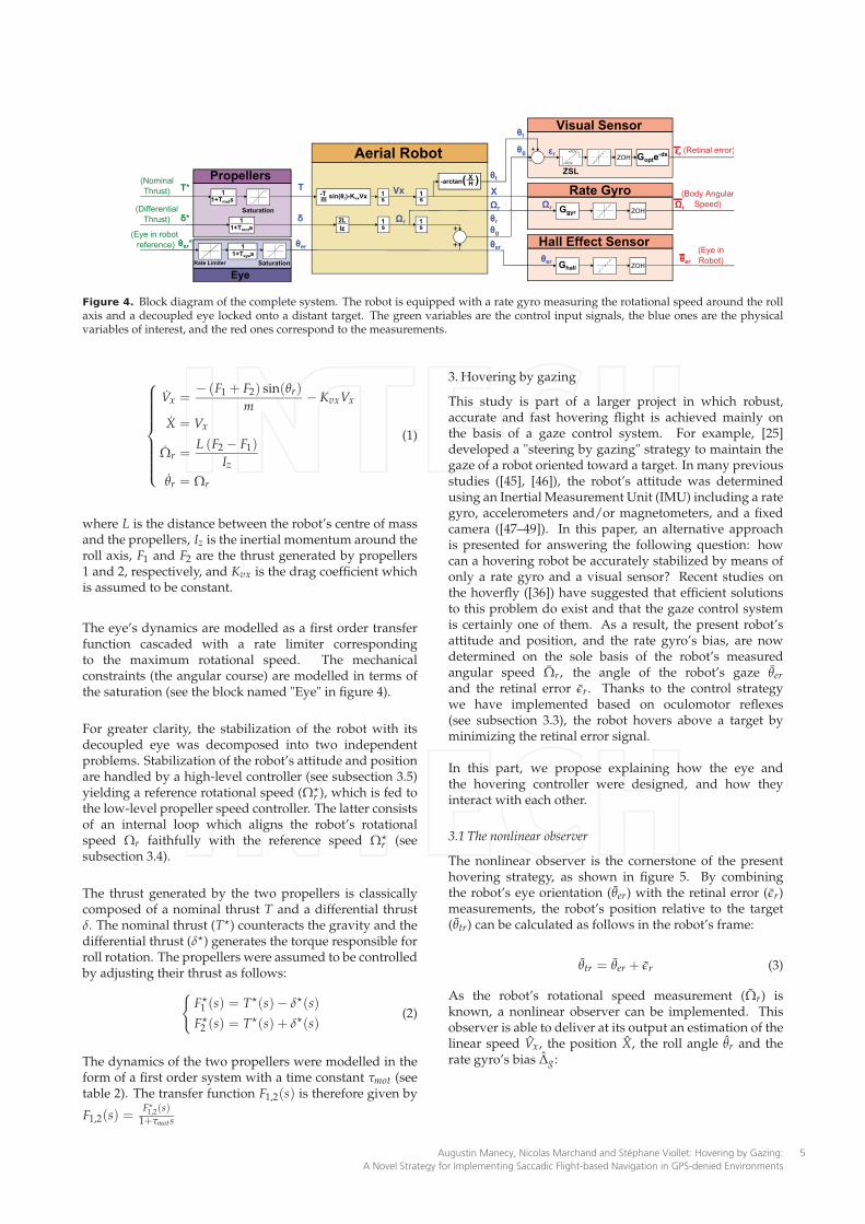
Figure 4. Block diagram of the complete system. The robot is equipped with a rate gyro measuring the rotational speed around the rollaxis and a decoupled eye locked onto a distant target. The green variables are the control input signals, the blue ones are the physicalvariables of interest, and the red ones correspond to the measurements.
Vx =− (F1 + F2) sin(θr)
m− KvxVx
X = Vx
Ωr =L (F2 − F1)
Iz
θr = Ωr
(1)
where L is the distance between the robot’s centre of massand the propellers, Iz is the inertial momentum around theroll axis, F1 and F2 are the thrust generated by propellers1 and 2, respectively, and Kvx is the drag coefficient whichis assumed to be constant.
The eye’s dynamics are modelled as a first order transferfunction cascaded with a rate limiter correspondingto the maximum rotational speed. The mechanicalconstraints (the angular course) are modelled in terms ofthe saturation (see the block named "Eye" in figure 4).
For greater clarity, the stabilization of the robot with itsdecoupled eye was decomposed into two independentproblems. Stabilization of the robot’s attitude and positionare handled by a high-level controller (see subsection 3.5)yielding a reference rotational speed (Ω⋆
r ), which is fed tothe low-level propeller speed controller. The latter consistsof an internal loop which aligns the robot’s rotationalspeed Ωr faithfully with the reference speed Ω
⋆
r (seesubsection 3.4).
The thrust generated by the two propellers is classicallycomposed of a nominal thrust T and a differential thrustδ. The nominal thrust (T⋆) counteracts the gravity and thedifferential thrust (δ⋆) generates the torque responsible forroll rotation. The propellers were assumed to be controlledby adjusting their thrust as follows:
F⋆
1 (s) = T⋆(s)− δ⋆(s)
F⋆
2 (s) = T⋆(s) + δ⋆(s)
(2)
The dynamics of the two propellers were modelled in theform of a first order system with a time constant τmot (seetable 2). The transfer function F1,2(s) is therefore given by
F1,2(s) =F⋆
1,2(s)1+τmots
3. Hovering by gazing
This study is part of a larger project in which robust,accurate and fast hovering flight is achieved mainly onthe basis of a gaze control system. For example, [25]developed a "steering by gazing" strategy to maintain thegaze of a robot oriented toward a target. In many previousstudies ([45], [46]), the robot’s attitude was determinedusing an Inertial Measurement Unit (IMU) including a rategyro, accelerometers and/or magnetometers, and a fixedcamera ([47–49]). In this paper, an alternative approachis presented for answering the following question: howcan a hovering robot be accurately stabilized by means ofonly a rate gyro and a visual sensor? Recent studies onthe hoverfly ([36]) have suggested that efficient solutionsto this problem do exist and that the gaze control systemis certainly one of them. As a result, the present robot’sattitude and position, and the rate gyro’s bias, are nowdetermined on the sole basis of the robot’s measuredangular speed Ωr, the angle of the robot’s gaze θer
and the retinal error ǫr. Thanks to the control strategywe have implemented based on oculomotor reflexes(see subsection 3.3), the robot hovers above a target byminimizing the retinal error signal.
In this part, we propose explaining how the eye andthe hovering controller were designed, and how theyinteract with each other.
3.1 The nonlinear observer
The nonlinear observer is the cornerstone of the presenthovering strategy, as shown in figure 5. By combiningthe robot’s eye orientation (θer) with the retinal error (ǫr)measurements, the robot’s position relative to the target(θtr) can be calculated as follows in the robot’s frame:
θtr = θer + ǫr (3)
As the robot’s rotational speed measurement (Ωr) isknown, a nonlinear observer can be implemented. Thisobserver is able to deliver at its output an estimation of thelinear speed Vx, the position X, the roll angle θr and therate gyro’s bias ∆g:
Augustin Manecy, Nicolas Marchand and Stéphane Viollet: Hovering by Gazing:
A Novel Strategy for Implementing Saccadic Flight-based Navigation in GPS-denied Environments
5
˙Vx˙X˙θr˙∆g
=
−Tm sin(θr)− KvxVx + L1 θtr
Vx + L2 θtr
Ωr − ∆g + L3 θtr
L4 θtr
θtr = − arctan
(X
H
)
︸ ︷︷ ︸
θg
−θr
(4)
Where θtr = (θer + ǫr︸ ︷︷ ︸
θtr
−θtr)
The implementation of a nonlinear observer was based onthe strongly nonlinear equation giving the evolution ofthe linear speed Vx (see equation (4)) and the nonlinear
output θtr (function of X and θr). Nonlinearities in ˙Vx givebetter estimation during transient, and nonlinearities in θtr
give a nonsteady state error in position estimation, evenwhen the robot is not above the target. The observer gain
L =(
L1 L2 L3 L4
)Twas tuned using the classical LQG
method and the system was linearized around the origin.
Remark 1: Assuming that the angular precision of thesensor is about 0.1°, the robot is able to estimate its positionwith a 0.5cm accuracy if it hovers at 2m above the target.This precision is much greater than that of a classical GPSdevice.
3.2 An unbiased rate gyro
Rate gyros always have a bias, resulting in a driftin the attitude estimation if they are not filtered andfitted. Classical methods ([3, 45, 46, 50, 51]) are basedon accelerometers to determine the gravity direction,and/or magnetometers to perform magnetic fieldmeasurements, and compensate for the rate gyrobias. The original method presented here relies, asoccurs in insects, on vision and proprioceptive sensors(specifying the eye’s orientation θer) to unbias the rategyro. If the gaze stabilization system is locked ontothe target, the rate gyro’s bias will therefore dependon the angular error θtr defined by equation (4). Inour case, the low-frequency inclination information,classically provided by accelerometers, is given here bythe proprioceptive measurement θer.
The rate gyro’s bias can be defined as follows:
Ωr = Ωr + ∆g + µ (5)
∆g = 0 (6)
Where Ωr is the actual rotational speed, ∆g is the rategyro’s bias, and µ is an unknown centred noise.
Remark 2: The value of θr in equation (4) is obtained fromequation (5). Ωr − ∆g is therefore simply the modelling
term accounting for the rate gyro’s bias and L3 θtr is theinnovative term. As mentioned above, the rate gyro’s biasis determined on the sole basis of the target angle error
( ˙∆g = L4 θtr).
3.3 Eye controller
The eye’s controller keeps the gaze locked onto a targetplaced on the ground. Since the field of view is verysmall, the closed loop gaze system has to act very fastand efficiently. The requisite efficiency is achieved usinga bio-inspired approach, involving a combination of threecomplementary oculomotor reflexes:• A rotational vestibulo-ocular reflex called the rVOR,
which has to counteract the effects of all the rotationsperformed by the robot. This reflex yields the signalθ⋆er_θr
, which is simply the opposite of the roll angle θr.• A translational vestibulo-ocular reflex called the tVOR
compensates for the effects of any robot’s translationsin the retina. The output signal θ⋆er_X , based on the
robot’s position X and its altitude H, contributes tokeeping the eye locked onto the target.
• A visual fixation reflex called the VFR, consists of avisual feedback loop with which any retinal signalerrors ǫr are cancelled by controlling the eye’sorientation θer via the control input signals θ⋆er_VFR (seefigure 5).
The VFR reflex plays a key role here. It is the main reflexserving to track the target under all conditions. Thanks tothis reflex, the robot is able to:• hover "robustly" above a target,• reject any lateral disturbances resulting from gusts of
wind by quickly correcting the eye’s orientation, whichis not possible if the robot has no decoupling, becauseof its relatively large inertia.
The VFR controller consists of a simple proportionalintegral controller, which keeps the retinal error close to 0°.This controller yields a reference angle (θ⋆er_VFR) in orderto contribute to the eye’s orientation, see equation (7).In short, this reflex is responsible for target tracking inevery situation, which is the first step towards hoveringrobustly and accurately determining the robot’s attitudeand position.
The VOR is composed of a combination of two reflexeskeeping the target in the FOV even if the robot is moving.VORs, which were directly inspired by the visual processesoccurring in insects, compensate for two kinds of robotmovements:• roll: the rVOR uses the roll angle estimation θr
provided by the nonlinear observer to compensate forany body rotations (θ⋆er_θr
= −θr),• lateral translation: the tVOR, which is based on the
estimation of the robot’s linear position, minimizes theeffects of any lateral displacements on the retinal error
ǫr, (θ⋆er_X = − arctan(
XH
)
).
The reference angle θ⋆er (see figure 5), which thereforeresults from the joint contribution of three reflexes (rVOR,tVOR and VFR), can be expressed as follows:
θ⋆er = θ⋆er_θr︸ ︷︷ ︸
rVOR
+ θ⋆er_X︸ ︷︷ ︸
tVOR
+ θ⋆er_VFR︸ ︷︷ ︸
VFR
(7)
Int J Adv Robot Syst, 2014, 11:66 | doi: 10.5772/584296
Controller
SetPoints
er_θr
θer_VFR
θer*
εr
-atan(X/H)^θer*
*θer_X**
-1
+-θr^X
^
Non LinearOBSERVER
Ωr
θer
Propellers Controller
δΩr* LQ state feedback+
-
Ωr LQG Observer
LQ state feedback
rVOR
tVOR
PIVFR
+++
X*
x
Attitude and position controller
Eye controller
Δg^
+θtr
θ
++
VXT
I
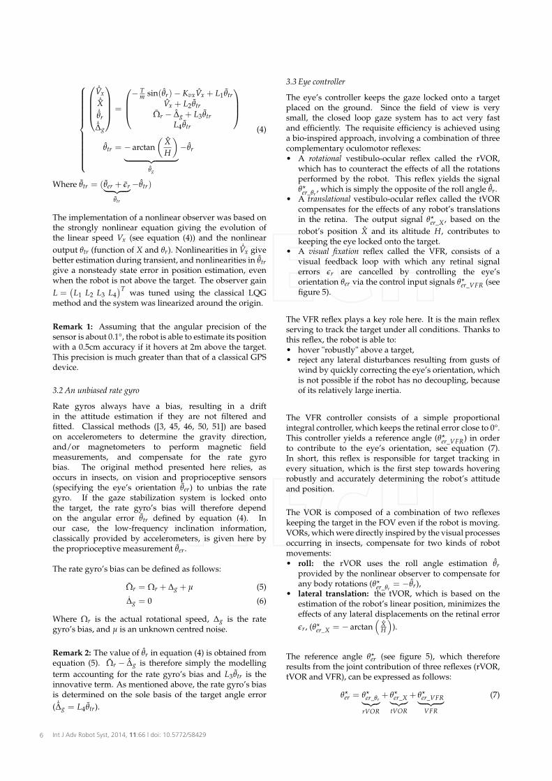
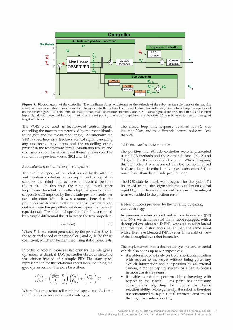
Figure 5. Block-diagram of the controller. The nonlinear observer determines the attitude of the robot on the sole basis of the angularspeed and eye orientation measurements. The eye controller is based on three Oculomotor Reflexes (ORs), which keep the eye lockedon the target regardless of the translational or rotational disturbances that may occur. Measured signals are presented in red and controlinput signals are presented in green. Note that the set-point T
IX, which is explained in subsection 4.2, can be used to make a change of
target of interest.
The VORs were used as feedforward control signalscancelling the movements perceived by the robot (thanksto the gyro and the eye-in-robot angle). Additionally, theVFR is used here as a feedback control signal cancellingany undetected movements and the modelling errorspresent in the feedforward terms. Simulation results anddiscussions about the efficiency of theses reflexes could befound in our previous works ([52] and [53]).
3.4 Rotational speed controller of the propellers
The rotational speed of the robot is used by the attitudeand position controller as an input control signal tostabilize the robot and achieve the desired position(figure 4). In this way, the rotational speed innerloop makes the robot faithfully adopt the speed rotationset-points (Ω⋆
r ) imposed by the attitude-position controller(see subsection 3.5). It was assumed here that thepropellers are driven directly by the thrust, which can bededuced from the propeller’s rotational speed in line withequation (8). The rotational speed is therefore controlledby a simple differential thrust between the two propellers.
Fi = cT .ω2i (8)
Where Fi is the thrust generated by the propeller i, ωi isthe rotational speed of the propeller i, and cT is the thrustcoefficient, which can be identified using static thrust tests.
In order to account more satisfactorily for the rate gyro’sdynamics, a classical LQG controller-observer structurewas chosen instead of a simple PID. The state spacerepresentation for the rotational speed loop, including thegyro dynamics, can therefore be written:
(
Ωr˙
Ωr
)
=
(
−2LIzτmot
01
τgyr
−1τgyr
)(
Ωr
Ωr
)
+
(
2LIzτmot
0
)
δ⋆ (9)
Where Ωr is the actual roll rotational speed and Ωr is therotational speed measured by the rate gyro.
The closed loop time response obtained for Ωr wasless than 20ms, and the differential control noise was lessthan 2%.
3.5 Position and attitude controller
The position and attitude controller were implementedusing LQR methods and the estimated states (Vx, X andθr) given by the nonlinear observer. When designingthis controller, it was assumed that the rotational speedfeedback loop described above (see subsection 3.4) ismuch faster than the attitude-position loop.
The LQR state feedback was designed for the system (1)linearized around the origin with the equilibrium controlinput Ωreq = 0. To cancel the steady state error, an integralterm was added to the position error.
4. New outlooks provided by the hovering by gazingcontrol strategy
In previous studies carried out at our laboratory ([52]and [53]), we demonstrated that a robot equipped with adecoupled eye (denoted D-EYE) was able to reject lateraland rotational disturbances better than the same robotwith a fixed eye (denoted F-EYE) even if the field of viewof the decoupled eye robot is smaller.
The implementation of a decoupled eye onboard an aerialvehicle also opens up new perspectives:• it enables a robot to finely control its horizontal position
with respect to the target without being given anyexplicit information about it position by an externalcamera, a motion capture system, or a GPS as occursin more classical systems,
• it enables a robot to perform shifted hovering withrespect to the target. This point has interestingconsequences regarding the robot’s disturbancerejection ability. More generally, the robot is thereforenot constrained to stay in a small restricted area aroundthe target (see subsection 4.1),
Augustin Manecy, Nicolas Marchand and Stéphane Viollet: Hovering by Gazing:
A Novel Strategy for Implementing Saccadic Flight-based Navigation in GPS-denied Environments
7
F-EYE robot D-EYE robot
x
y
X
H FOV = ± 25°
x
y
X
θt
Max. Lat. Dist.
MLDR
Max. Lat. Dist.
MLDL
Left Dist. Right Dist.
Δmin
eye orientationeye orientation
Δminθt
H
XLres
Max. Lat. Dist.
MLDR
Max. Lat. Dist.
MLDL
XRres
a)
-6 -4 -2 0 2 4 60
0.5
1
1.5
2
2.5
Maxim
um
Late
ral D
istu
rbance [m
]
Relative position (shift) [m]
MLDR
for D-EYE
MLDL
for D-EYE
MLDR
for F-EYE
MLDL
for F-EYE
Decoupled eye only Decoupled eye onlyb)
FOV = ± 5°
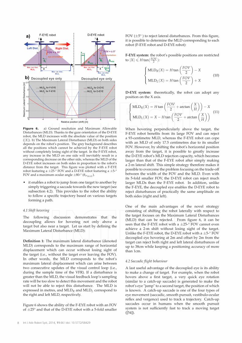
Figure 6. a) Ground resolution and Maximum AllowableDisturbances (MLD). Thanks to the gaze orientation of the D-EYErobot, the MLD increases with the absolute value of the position(|X|). b) The Maximum Lateral Disturbance (MLD) on both sidesdepends on the robot’s position. The grey background describesall the positions which cannot be achieved by the F-EYE robotwithout completely losing sight of the target. In the F-EYE robot,any increase in the MLD on one side will inevitably result in acorresponding decrease on the other side, whereas the MLD of theD-EYE robot increases on both sides in proportion to the robot’sdistance from the target. This figure was plotted with a F-EYErobot featuring a ±25-° FOV and a D-EYE robot featuring a ±5-°FOV and a maximum ocular angle ±80-° (θerMAX
).
• it enables a robot to jump from one target to another bysimply triggering a saccade towards the new target (seesubsection 4.2). This provides to the robot the abilityto follow a specific trajectory based on various targetsforming a path.
4.1 Shift hovering
The following discussion demonstrates that thedecoupling allows for hovering not only above atarget but also near a target. Let us start by defining theMaximum Lateral Disturbance (MLD):
Definition 1: The maximum lateral disturbance (denotedMLD) corresponds to the maximum range of horizontaldisplacement which can occur without losing sight ofthe target (i.e., without the target ever leaving the FOV).In other words, the MLD corresponds to the robot’smaximum lateral displacement which can arise betweentwo consecutive updates of the visual control loop (i.e.,during the sample time of the VFR). If a disturbance isgreater than the MLD, the visual feedback loop’s samplingrate will be too slow to detect this movement and the robotwill not be able to reject this disturbance. The MLD isexpressed in metres, and MLDR and MLDL correspond tothe right and left MLD, respectively.
Figure 6 shows the ability of the F-EYE robot with an FOVof ±25° and that of the D-EYE robot with a 5-fold smaller
FOV (±5° ) to reject lateral disturbances. From this figure,it is possible to determine the MLD corresponding to eachrobot (F-EYE robot and D-EYE robot):
F-EYE system: the robot’s possible positions are restricted
to |X| H tan( FOV2 ):
MLDR(X) = H tan
(
FOV
2
)
− X
MLDL(X) = H tan
(
FOV
2
)
+ X
(10)
D-EYE system: theoretically, the robot can adopt anyposition on the X axis.
MLDR(X) = H tan
(
FOV
2+ arctan
(
X
H
))
− X
MLDL(X) = X − H tan
(
FOV
2+ arctan
(
X
H
)) (11)
When hovering perpendicularly above the target, theF-EYE robot benefits from its large FOV and can rejecta 93-centimetre MLD, whereas the F-EYE robot can copewith an MLD of only 17.5 centimetres due to its smallerFOV. However, by shifting the robot’s horizontal positionaway from the target, it is possible to greatly increasethe D-EYE robot’s MLD rejection capacity, which becomeslarger than that of the F-EYE robot after simply makinga 2-m lateral shift. This simple strategy therefore makes itpossible to overcome the problem focusing on the trade-offbetween the width of the FOV and the MLD. Even withits 5-fold smaller FOV, the D-EYE robot can reject muchlarger MLDs than the F-EYE robot. In addition, unlikethe F-EYE, the decoupled eye enables the D-EYE robot toreject disturbances of practically the same amplitude onboth sides (right and left).
One of the main advantages of the novel strategyconsisting of shifting the robot laterally with respect tothe target focuses on the Maximum Lateral Disturbances(MLD) that can be rejected. From figure 6, it can beseen that the F-EYE robot with a ±25-° FOV cannot evenachieve a 2-m shift without losing sight of the target.Unlike the F-EYE robot, the D-EYE robot with a ±5-° FOVdecoupled eye hovering at 2m and offset by 2m from thetarget can reject both right and left lateral disturbances ofup to 38cm while keeping a positioning accuracy of morethan 1cm.
4.2 Saccadic flight behaviour
A last useful advantage of the decoupled eye is its abilityto make a change of target. For example, when the robothovers above a first target, a very quick eye rotation(similar to a catch-up saccade) is generated to make therobot’s eye "jump" to a second target, the position of whichis known. A catch-up saccade is one of the four types ofeye movement (saccadic, smooth pursuit, vestibulo-ocularreflex and vergence) used to track a trajectory. Catch-upsaccades occur in humans when the smooth pursuitsystem is not sufficiently fast to track a moving target([54]).
Int J Adv Robot Syst, 2014, 11:66 | doi: 10.5772/584298
In this study, this mechanism was used first to make therobot shift from one target to another. Like the steering bygazing strategy ([25]), the aerial robot will move towardthe target at which its gaze is looking.
4.2.1. Notations and implications:
Here we define some notations used to distinguishbetween the variables used in the various reference frames:
AB
U describes the variable U from A (the object in terms ofwhich the vector is expressed) in the frame of reference B
( in which the measurements are made.)
For example, RI
X gives the actual position of the robot R in
the inertial frame I and RT
X⋆ denotes the reference positionof the robot R relative to the target frame T .
Three frames of reference were therefore used in thisstudy:
- the Robot’s frame of reference, denoted R,- the Inertial frame, denoted I ,- the Target’s frame, denoted T .
Remark 1: Note that in the previous part, the target frameT was the same as the inertial frame I because the twoorigins were the same, i.e.,: T
IX = XT and T
TX = 0.
The relation between the estimated robot’s position in theinertial frame, the estimated robot’s position in the target’sframe and the target’s position in the inertial frame can bewritten:
RI X = R
T X + TIX (12)
Where TI
X is the position of the current target in the inertialframe. The observer described by equation (4) thereforebecomes:
RT
˙VxRT
˙XRT
˙θr
RT
˙∆g
=
− Tm sin(R
Tθr)− Kvx
RT
Vx + L1RT
θtrRT
Vx + L2RT
θtrRT
Ωr −RT
∆g + L3RT
θtr
L4RT
θtr
RT X = R
I X −TI X
RT θtr = − arctan
(
RT
XRT
H
)
−RT θr
(13)
where RT
θtr =RT
θtr −RT
θtr
4.2.2. "Target Jump" procedure:
To make the robot shift from one target to another, a simplechange of variable suffices. The previous value of thetarget’s position is then replaced by the new one. Thecoordinates of the new target just need to be updated asfollows:
TIX(t) = T
IXk before jump. (14)
TIX(t + ∆t) = T
IXk+1 after jump. (15)
Where ∆t corresponds to the nonlinear observer’ssampling time and T
IXk with the subscript k or k + 1
corresponds to the target’s identifier. TI
Xk and TI
Xk+1 are
therefore the position of the target k before the "targetjump" and the position of target k + 1 after the "targetjump", respectively.
The eye’s "jump" (or saccade) is then expressed bychanging the value of the feedforward term θ
⋆
er_X , which
is written with the new notation: θ⋆
er_X = − arctan( R
TX
RT
H
)
.
When the operator wants to make the robot changetarget, he/she just needs to send the robot the new targetcoordinates, expressed in the inertial frame (T
IXk).
Once the target’s new coordinates have been specified,the robot immediately changes its eye orientation andre-positions itself appropriately with respect to thereference R
TX⋆. A simulation of the robot’s target-jumping
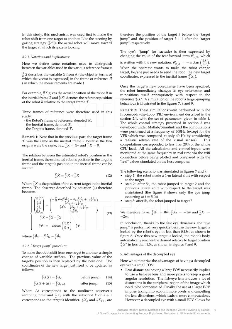
behaviour is illustrated in the figures 7, 8 and 9.
Remark 2: These simulations were performed with theProcessor-In-the-Loop (PIL) environment described in thesection 2.1, with the set of parameters given in table 1.The whole control strategy presented in section 3 wasdeveloped under Matlab/Simulink and the computationswere performed at a frequency of 400Hz (except for theVFR which was computed at only 40 Hz by consideringa realistic refresh rate of the visual sensor). Thiscomputations corresponded to less than 20% of the wholeCPU load. All the calculations and control inputs weremonitored at the same frequency in real time via the wificonnection before being plotted and compared with the"real" values simulated on the host computer.
The following scenario was simulated in figures 7 and 9:• step 1: the robot made a 1-m lateral shift with respect
to the target• step 2: after 5s, the robot jumped to target 2 and the
previous lateral shift with respect to the target wasmaintained (the figure 8 shows only the eye jumpoccurring at t = 5.0s)
• step 3: after 5s, the robot jumped to target 3
We therefore have: TI
X1 = 0m, TI
X2 = −1m and TI
X3 =−2m.
In conclusion, thanks to the fast eye dynamics, the "eyejump" is performed very quickly because the new target islocked by the robot’s eye in less than 0.13s, as shown infigure 8. Once this new target is locked, the robot’s bodyautomatically reaches the desired relative to target positionRT
X⋆ in less than 1.5s, as shown in figures 7 and 9.
5. Advantages of the decoupled eye
Here we summarize the advantages of having a decoupledeye with a small FOV:
• Less distortion: having a large FOV necessarily impliesto use a fish-eye lens and more pixels to keep a goodangular resolution. The fish-eye lens induces a lot ofdistortions in the peripheral region of the image whichneed to be compensated. Finally, the use of a large FOVimplies taking into account more pixels and cancellingthe lens distortions, which leads to more computations.However, a decoupled eye with a small FOV allows for
Augustin Manecy, Nicolas Marchand and Stéphane Viollet: Hovering by Gazing:
A Novel Strategy for Implementing Saccadic Flight-based Navigation in GPS-denied Environments
9
-1
0
1
2
Hor
izon
tal p
ositi
on X
[m]
-50
0
50
θ er[d
eg]
0 5 10 15-20
-10
0
10
time [s]
FOV
Ret
inal
err
or [d
eg]
Target 1 Target 2 Target 3
a)
c)
b)
Target lock time0.13 s
Target lock time0.13 s
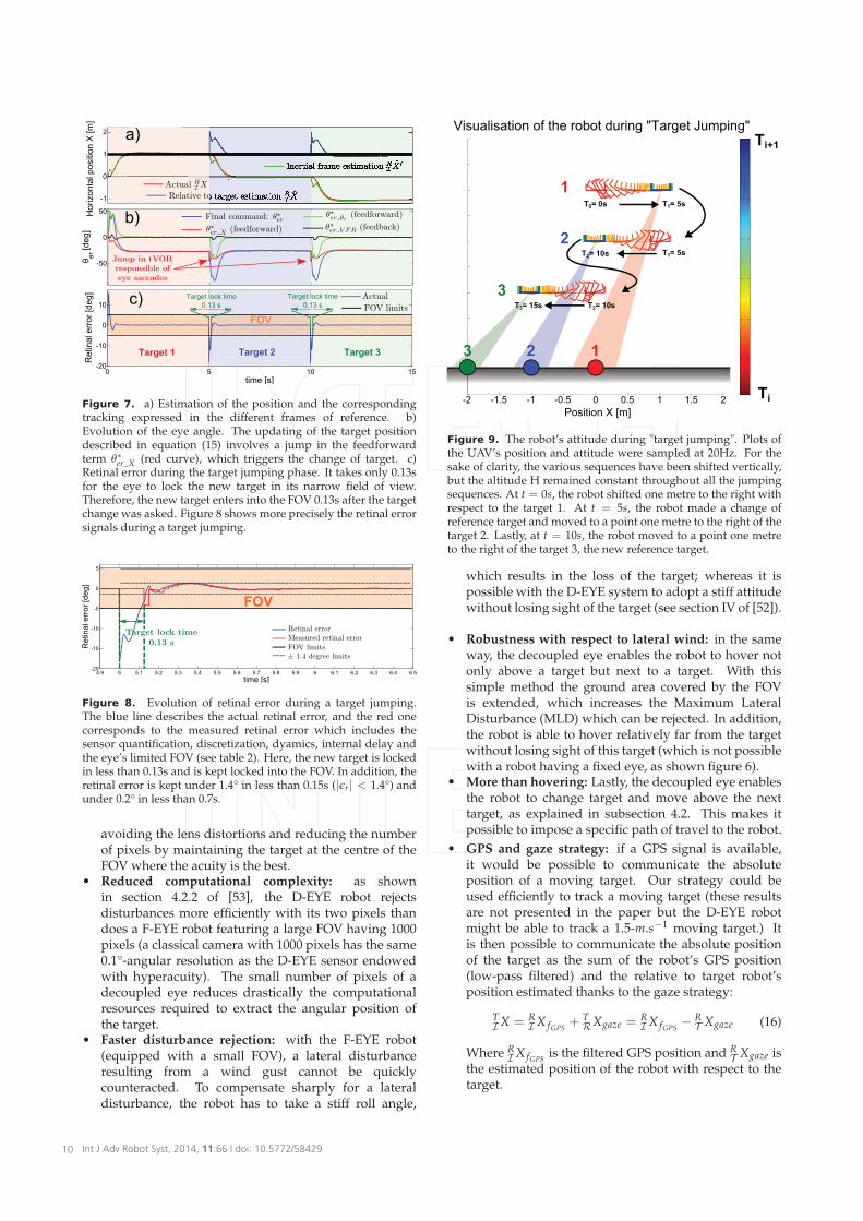
Figure 7. a) Estimation of the position and the correspondingtracking expressed in the different frames of reference. b)Evolution of the eye angle. The updating of the target positiondescribed in equation (15) involves a jump in the feedforwardterm θ
∗er_X (red curve), which triggers the change of target. c)
Retinal error during the target jumping phase. It takes only 0.13sfor the eye to lock the new target in its narrow field of view.Therefore, the new target enters into the FOV 0.13s after the targetchange was asked. Figure 8 shows more precisely the retinal errorsignals during a target jumping.
4.9 5 5.1 5.2 5.3 5.4 5.5 5.6 5.7 5.8 5.9 6 6.1 6.2 6.3 6.4 6.5-20
-15
-10
-5
0
5
time [s]
Ret
inal
err
or [d
eg]
FOV
Figure 8. Evolution of retinal error during a target jumping.The blue line describes the actual retinal error, and the red onecorresponds to the measured retinal error which includes thesensor quantification, discretization, dyamics, internal delay andthe eye’s limited FOV (see table 2). Here, the new target is lockedin less than 0.13s and is kept locked into the FOV. In addition, theretinal error is kept under 1.4° in less than 0.15s (|ǫr | < 1.4°) andunder 0.2° in less than 0.7s.
avoiding the lens distortions and reducing the numberof pixels by maintaining the target at the centre of theFOV where the acuity is the best.
• Reduced computational complexity: as shownin section 4.2.2 of [53], the D-EYE robot rejectsdisturbances more efficiently with its two pixels thandoes a F-EYE robot featuring a large FOV having 1000pixels (a classical camera with 1000 pixels has the same0.1°-angular resolution as the D-EYE sensor endowedwith hyperacuity). The small number of pixels of adecoupled eye reduces drastically the computationalresources required to extract the angular position ofthe target.
• Faster disturbance rejection: with the F-EYE robot(equipped with a small FOV), a lateral disturbanceresulting from a wind gust cannot be quicklycounteracted. To compensate sharply for a lateraldisturbance, the robot has to take a stiff roll angle,
-2 -1.5 -1 -0.5 0 0.5 1 1.5 2
Visualisation of the robot during "Target Jumping"
T0= 0s
Position X [m]
1 23
T1= 5s T2= 10s
T1= 5s
T2= 10s T3= 15s
1
2
3
Ti
Ti+1
Figure 9. The robot’s attitude during "target jumping". Plots ofthe UAV’s position and attitude were sampled at 20Hz. For thesake of clarity, the various sequences have been shifted vertically,but the altitude H remained constant throughout all the jumpingsequences. At t = 0s, the robot shifted one metre to the right withrespect to the target 1. At t = 5s, the robot made a change ofreference target and moved to a point one metre to the right of thetarget 2. Lastly, at t = 10s, the robot moved to a point one metreto the right of the target 3, the new reference target.
which results in the loss of the target; whereas it ispossible with the D-EYE system to adopt a stiff attitudewithout losing sight of the target (see section IV of [52]).
• Robustness with respect to lateral wind: in the sameway, the decoupled eye enables the robot to hover notonly above a target but next to a target. With thissimple method the ground area covered by the FOVis extended, which increases the Maximum LateralDisturbance (MLD) which can be rejected. In addition,the robot is able to hover relatively far from the targetwithout losing sight of this target (which is not possiblewith a robot having a fixed eye, as shown figure 6).
• More than hovering: Lastly, the decoupled eye enablesthe robot to change target and move above the nexttarget, as explained in subsection 4.2. This makes itpossible to impose a specific path of travel to the robot.
• GPS and gaze strategy: if a GPS signal is available,it would be possible to communicate the absoluteposition of a moving target. Our strategy could beused efficiently to track a moving target (these resultsare not presented in the paper but the D-EYE robotmight be able to track a 1.5-m.s−1 moving target.) Itis then possible to communicate the absolute positionof the target as the sum of the robot’s GPS position(low-pass filtered) and the relative to target robot’sposition estimated thanks to the gaze strategy:
TIX = R
I X fGPS+ T
RXgaze =RI X fGPS
− RT Xgaze (16)
Where RI X fGPS
is the filtered GPS position and RT Xgaze is
the estimated position of the robot with respect to thetarget.
Int J Adv Robot Syst, 2014, 11:66 | doi: 10.5772/5842910
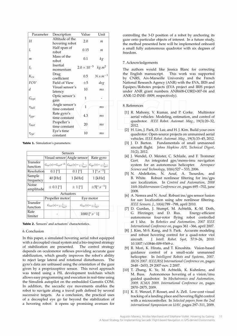
Parameter Description Value Unit
HAltitude of thehovering robot
2.0 m
LHalf span ofrobot
0.15 m
mMass of therobot
0.1 kg
IzInertialmomentum
2.0 × 10⁻⁵ kg.m2
KvxDragcoefficient
0.5 N.s.m−1
FOV Field of View ±5 deg
dVisual sensor’slatency
10 ms
GoptOptic sensor’sgain
1 -
τhallAngle sensor’stime constant
1 ms
τgyrRate gyro’stime constant
4.3 ms
τmotPropeller’stime constant
20 ms
τeyeEye’s timeconstant
10 ms
Table 1. Simulation’s parameters.
Sensors
Visual sensor Angle sensor Rate gyro
Transferfunction
Gopt ( s) =Gopte−ds Ghall(s)=
11+τhall s Ggyr(s)=
11+τgyr s
Resolution 0.1 [°] 0.1 [°] 1 [°.s−1]
Samplefrequency
40 [Hz] 1 [kHz] 1 [kHz]
Noiseamplitude
± 0.1 [°] ± 1 [°] ±5[°.s−1]
Actuators
Propeller motor Eye motor
Transferfunction
Gmot(s)=1
1+τmots Geye(s)=1
1+τeye s
Ratelimiter
- 1000 [°.s−1]
Table 2. Sensors’ and actuators’ characteristics.
6. Conclusion
In this paper, a simulated hovering aerial robot equippedwith a decoupled visual system and a bio-inspired strategyof stabilization are presented. The control strategydepends on oculomotor reflexes providing accurate gazestabilization, which greatly improves the robot’s abilityto reject large lateral and rotational disturbances. Thegyro’s data are unbiased using the orientation of the gazegiven by a proprioceptive sensor. This novel approachwas tested using a PIL development toolchain whichallows easy programming and execution in real-time usingthe Simulink autopilot on the embedded Gumstix COM.In addition, the saccadic eye movements enables therobot to navigate along a travel path defined by severalsuccessive targets. As a conclusion, the practical usesof a decoupled eye go far beyond the stabilization ofa hovering robot: it opens up promising avenues for
controlling the 3-D position of a robot by anchoring itsgaze onto particular objects of interest. In a future study,the method presented here will be implemented onboarda small fully autonomous quadrotor with six degrees offreedom.
7. Acknowledgements
The authors would like Jessica Blanc for correctingthe English manuscript. This work was supportedby CNRS, Aix-Marseille University and the FrenchNational Research Agency (ANR) with the EVA, IRIS andEquipex/Robotex projects (EVA project and IRIS projectunder ANR grant numbers ANR608-CORD-007-04 andANR-12-INSE- 0009, respectively).
8. References
[1] R. Mahony, V. Kumar, and P. Corke. Multirotoraerial vehicles: Modeling, estimation, and control ofquadrotor. IEEE Robot. Automat. Mag., 19(3):20–32,2012.
[2] H. Lim, J. Park, D. Lee, and H. J. Kim. Build your ownquadrotor: Open-source projects on unmanned aerialvehicles. IEEE Robot. Automat. Mag., 19(3):33–45, 2012.
[3] J. D. Barton. Fundamentals of small unmannedaircraft flight. Johns Hopkins APL Technical Digest,31(2), 2012.
[4] J. Wendel, O. Meister, C. Schlaile, and F. TrommerGert. An integrated gps/mems-imu navigationsystem for an autonomous helicopter. AerospaceScience and Technology, 10(6):527 – 533, 2006.
[5] N. Abdelkrim, N. Aouf, A. Tsourdos, andB. White. Robust nonlinear filtering for ins/gpsuav localization. In Control and Automation, 200816th Mediterranean Conference on, pages 695 –702, june2008.
[6] A. Nemra and N. Aouf. Robust ins/gps sensor fusionfor uav localization using sdre nonlinear filtering.IEEE Sensors. J., 10(4):789 –798, april 2010.
[7] D. Gurdan, J. Stumpf, M. Achtelik, K.-M. Doth,G. Hirzinger, and D. Rus. Energy-efficientautonomous four-rotor flying robot controlledat 1 khz. In Robotics and Automation, 2007 IEEEInternational Conference on, pages 361 –366, april 2007.
[8] J. Kim, M-S. Kang, and S. Park. Accurate modelingand robust hovering control for a quad-rotor vtolaircraft. J. Intell. Robot. Syst, 57:9–26, 2010.10.1007/s10846-009-9369-z.
[9] R. Mori, K. Hirata, and T. Kinoshita. Vision-basedguidance control of a small-scale unmannedhelicopter. In Intelligent Robots and Systems, 2007.IROS 2007. IEEE/RSJ International Conference on, pages2648 –2653, 29 2007-nov. 2 2007.
[10] T. Zhang, K. Ye, M. Achtelik, K. Kuhnlenz, andM. Buss. Autonomous hovering of a vision/imuguided quadrotor. In Mechatronics and Automation,2009. ICMA 2009. International Conference on, pages2870–2875, 2009.
[11] K. E. Wenzel, P. Rosset, and A. Zell. Low-cost visualtracking of a landing place and hovering flight controlwith a microcontroller. In Selected papers from the 2ndinternational Symposium on UAV, pages 297–311, 2009.
Augustin Manecy, Nicolas Marchand and Stéphane Viollet: Hovering by Gazing:
A Novel Strategy for Implementing Saccadic Flight-based Navigation in GPS-denied Environments
11
[12] S. Yang, S. A. Scherer, and A. Zell. An onboardmonocular vision system for autonomous takeoff,hovering and landing of a micro aerial vehicle. J.Intell. Robot. Syst, 69(1-4):499–515, 2013.
[13] B. Herissé, T. Hamel, R. Mahony, and F.-X. Russotto.Landing a vtol unmanned aerial vehicle on amoving platform using optical flow. Robotics, IEEETransactions on, 28(1):77–89, Feb. 2012.
[14] F. Kendoul, I. Fantoni, and K. Nonami. Opticflow-based vision system for autonomous 3dlocalization and control of small aerial vehicles.Robot. Auton. Syst, 57(6-7):591–602, 2009.
[15] E. Rondon, L.-R. Garcia-Carrillo, and I. Fantoni.Vision-based altitude, position and speed regulationof a quadrotor rotorcraft. In Intelligent Robots andSystems (IROS), 2010 IEEE/RSJ International Conferenceon, pages 628–633, 2010.
[16] F. Kendoul, I. Fantoni, and K. Nonami. Guidanceand nonlinear control system for autonomous flightof minirotorcraft unmanned aerial vehicles. J. Field.Robot., 27(3):311–334, 2010.
[17] M. Bošnak, D. Matko, and S. Blažic. Quadrocopterhovering using position-estimation information frominertial sensors and a high-delay video system. J.Intell. Robot. Syst, 67(1):43–60, 2012.
[18] S. Ahrens, D. Levine, G. Andrews, and J.P. How.Vision-based guidance and control of a hoveringvehicle in unknown, gps-denied environments. InRobotics and Automation, 2009. ICRA ’09. IEEEInternational Conference on, pages 2643–2648, 2009.
[19] L. Kerhuel, S. Viollet, and N. Franceschini. The vodkasensor: A bio-inspired hyperacute optical positionsensing device. IEEE Sensors. J., 12(2):315 –324, feb.2012.
[20] R. Juston, L. Kerhuel, N. Franceschini, and S. Viollet.Hyperacute edge and bar detection in a bioinspiredoptical position sensing device. Mechatronics,IEEE/ASME Transactions on, PP(99):1–10, 2013.
[21] I. F. Mondragón, M. A. Olivares-Méndez, P. Campoy,C. Martínez, and L. Mejias. Unmanned aerial vehiclesuavs attitude, height, motion estimation and controlusing visual systems. Auton. Robot., 29:17–34, 2010.
[22] D. H. Ballard. Animate vision. Artificial Intelligence,48(1):57 – 86, 1991.
[23] G. Westheimer. Visual hyperacuity. Ottoson, SensoryPhysiology 1, Springer, Berlin, 1981.
[24] S. Viollet and N. Franceschini. A high speed gazecontrol system based on the vestibulo-ocular reflex.Robot. Auton. Syst, 50:147–161, 2005.
[25] L. Kerhuel, S. Viollet, and N. Franceschini. Steeringby gazing: An efficient biomimetic control strategyfor visually guided micro aerial vehicles. Robotics,IEEE Transactions on, 26(2):307 –319, april 2010.
[26] R. Juston and S. Viollet. A miniature bio-inspiredposition sensing device for the control of micro-aerialrobots. In Intelligent Robots and Systems (IROS), 2012IEEE/RSJ International Conference on, pages 1118–1124,2012.
[27] R.C. Arkin. Behavior-based robotics. MIT press, 1998.[28] B. Webb. What does robotics offer animal behaviour?
Animal Behaviour, 60(5):545 – 558, 2000.
[29] G. K. Taylor and H. G. Krapp. Sensory systems andflight stability: What do insects measure and why?In J. Casas and S.J. Simpson, editors, Insect Mechanicsand Control, volume 34 of Advances in Insect Physiology,pages 231 – 316. Academic Press, 2007.
[30] J.H. Hateren and C. Schilstra. Blowfly flight and opticflow. ii. head movements during flight. J. Exp. Biol,202(11):1491, 1999.
[31] N. Boeddeker and J. M. Hemmi. Visual gaze controlduring peering flight manoeuvres in honeybees.Proceedings of the Royal Society B: Biological Sciences,pages –, 2009.
[32] S. Viollet and J. Zeil. Feed-forward and visualfeed-back control of head roll orientation in wasps(polistes humilis, vespidae, hymenoptera). J. Exp.Biol, 2013.
[33] T. S. Collett and M. F. Land. Visual control of flightbehaviour in the hoverflysyritta pipiens l. J. Comp.Physiol., 99(1):1–66, March 1975.
[34] B. R. H. Geurten, R. Kern, E. Braun, and M. Egelhaaf.A syntax of hoverfly flight prototypes. J. Exp. Biol,213(14):2461–2475, 2010.
[35] J. E. Niven. Visual motion: homing in on small targetdetectors. J. Curr. Biol., 16(8):R292–R294, Apr 2006.
[36] W. Wijngaard. Accuracy of insect position controlas revealed by hovering male eristalis nemorum.In Jan Bruin, editor, Proceedings of the NetherlandsEntomological Society Meeting, volume Volume 21,page 75, 2010.
[37] K. Nordström, P. D. Barnett, and D. C. O’Carroll.Insect detection of small targets moving in visualclutter. PLOS Biology, 4(3):e54, Mar 2006.
[38] R. Hengstenberg. Mechanosensorey control ofcompensatory head roll during flight in the blowflycalliphora erythrocephala meig. J. Comp. Physiol.,163:151–165, 1988.
[39] G. Nalbach. The halteres of the blowfly calliphora. J.Comp. Physiol., 173:293–300, 1993.
[40] G. Nalbach and R. Hengstenberg. The halteres ofthe blowfly calliphora. J. Comp. Physiol., 175:695–708,1994.
[41] N. Boeddeker, R. Kern, and M. Egelhaaf. Chasing adummy target: smooth pursuit and velocity controlin male blowflies. In Proc. R. Soc. Lond.B 270, pages393–399, 2003.
[42] S. D. Wiederman, P. A. Shoemaker, and D.C.O’Carroll. A model for the detection of movingtargets in visual clutter inspired by insect physiology.PLOS. ONE., 3(7):e2784, 07 2008.
[43] N.J. Strausfeld, H.S. Seyan, and J.J. Milde. The neckmotor system of the fly calliphora erythrocephala.1. muscles and motor neurons. J. Comp. Physiol., A160:205–224, 1987.
[44] T. Preuss and R. Hengstenberg. Structureand kinematics of the prosternal organs andtheir influence on head position in the blowflycalliphora erythrocephala meig. J. Comp. Physiol.,171(4):483–493, 1992.
[45] R. Mahony, T. Hamel, and J.-M. Pflimlin. Nonlinearcomplementary filters on the special orthogonalgroup. Automatic Control, IEEE Transactions on,53(5):1203 –1218, june 2008.
Int J Adv Robot Syst, 2014, 11:66 | doi: 10.5772/5842912
[46] E. Salaün and P. Martin. Design and implementationof a low-cost observer-based attitude and headingreference system. Control Engineering Practice,18(7):712–722, 2010.
[47] L. Meier, P. Tanskanen, F. Fraundorfer, andM. Pollefeys. Pixhawk: A system for autonomousflight using onboard computer vision. In IEEEInternational Conference on Robotics and Automation(ICRA), pages 2992–2997, 2011.
[48] V. Ghadiok, J. Goldin, and W. Ren. On thedesign and development of attitude stabilization,vision-based navigation, and aerial gripping for alow-cost quadrotor. Auton. Robot., 33:41–68, 2012.10.1007/s10514-012-9286-z.
[49] S. Weiss, D. Scaramuzza, and R. Siegwart.Monocular-slam-based navigation for autonomousmicro helicopters in gps-denied environments. J.Field. Robot., 28(6):854–874, 2011.
[50] R. Mahony, M. Euston, J. Kim, P. Coote, andT. Hamel. A non-linear observer for attitudeestimation of a fixed-wing unmanned aerial vehicle
without gps measurements. Transactions of theInstitute of Measurement and Control, 33 (6):699–717,2011.
[51] J.F.G. Castellanos, S. Lesecq, N. Marchand,and J. Delamare. A low-cost air data attitudeheading reference system for the tourism airplaneapplications. In Sensors, IEEE, pages 4 pp.–, 2005.
[52] A. Manecy, S. Viollet, and N. Marchand. Bio-inspiredhovering control for an aerial robot equipped witha decoupled eye and a rate gyro. In IntelligentRobots and Systems (IROS), 2012 IEEE/RSJ InternationalConference on, pages 1110–1117, 2012.
[53] A. Manecy, R. Juston, N. Marchand, and S. Viollet.Decoupling the eye: A key toward a robust hoveringfor sighted aerial robots. In Qiping Chu, Bob Mulder,Daniel Choukroun, Erik-Jan Kampen, Coen Visser,and Gertjan Looye, editors, Advances in AerospaceGuidance, Navigation and Control, pages 317–336.Springer Berlin Heidelberg, 2013.
[54] RHS Carpenter. Movements of the eye. Pion London,1988.
Augustin Manecy, Nicolas Marchand and Stéphane Viollet: Hovering by Gazing:
A Novel Strategy for Implementing Saccadic Flight-based Navigation in GPS-denied Environments
13