Houstoun Gate Locomotive Works - HGLW
7
1 of 7 Houstoun Gate Locomotive Works ‘Gordon’ 4-Wheel Drive Chassis Assembly Instructions It is suggested that you read these instructions through before commencing construction. A minimum of tools are needed to assemble the kit. Sandpaper and sanding block, some strong rubber bands or weights to hold parts in place while the glue dries. You will also need a small cross head screwdriver to attach the motor and soldering equipment to assemble the wiring. The included motor is designed to run on 2 AA batteries (Not included). These can be either rechargeable or disposable. (In an R/C setup you can use a maximum of 6v with this motor) This kit requires glue and paint to complete. It can be built entirely with PVA (exterior type) or aliphatic resin, except for the grille mesh which is best attached with epoxy resin. A favourite glue is Titebond 3 aliphatic. Excess glue can be wiped away with a damp rag. As MDF is by its nature not moisture proof the model should sealed before use with MDF sealer, thinned PVA or automotive primer. The cut edges may need more than one application of primer to seal them. To finish the model cans of automotive spray paint work well and give a good finish. If brush painting then use acrylic or enamel paint. Kit Contents 4WD Chassis 2 x 3mm fret 2 x 1.5mm hub sheet 2 x Brass wire 1 x drive belt 1 x wheel set with gear 1 x wheel set w/o gear 1 x Motor with worm 1 x spare worm 4 x brass bearing 8 x M3 washers 2 x M2 washers 2 x self tap screws 1 x 2 cell AA battery box 1 x DPDT switch Two worm gears are included, one is a spare. In use the worm will wear but it is easy and cheap to replace. If you find it wears very quickly view the troubleshooting at the end of these instructions or contact the helpline at [email protected] .
Transcript of Houstoun Gate Locomotive Works - HGLW

1 of 7
Houstoun Gate Locomotive Works ‘Gordon’ 4-Wheel Drive Chassis Assembly Instructions
It is suggested that you read these instructions through before commencing construction.
A minimum of tools are needed to assemble the kit. Sandpaper and sanding block, some strong rubber bands or weights to hold parts in place while the glue dries. You will also need a small cross head screwdriver to attach the motor and soldering equipment to assemble the wiring. The included motor is designed to run on 2 AA batteries (Not included). These can be either rechargeable or disposable. (In an R/C setup you can use a maximum of 6v with this motor) This kit requires glue and paint to complete. It can be built entirely with PVA (exterior type) or aliphatic resin, except for the grille mesh which is best attached with epoxy resin. A favourite glue is Titebond 3 aliphatic. Excess glue can be wiped away with a damp rag. As MDF is by its nature not moisture proof the model should sealed before use with MDF sealer, thinned PVA or automotive primer. The cut edges may need more than one application of primer to seal them. To finish the model cans of automotive spray paint work well and give a good finish. If brush painting then use acrylic or enamel paint. Kit Contents 4WD Chassis 2 x 3mm fret 2 x 1.5mm hub sheet 2 x Brass wire 1 x drive belt 1 x wheel set with gear 1 x wheel set w/o gear 1 x Motor with worm 1 x spare worm 4 x brass bearing 8 x M3 washers 2 x M2 washers 2 x self tap screws 1 x 2 cell AA battery box 1 x DPDT switch Two worm gears are included, one is a spare. In use the worm will wear but it is easy and cheap to replace. If you find it wears very quickly view the troubleshooting at the end of these instructions or contact the helpline at [email protected] .

2 of 7
Assembly Carefully separate the parts from their sheets. Wriggling them lightly is normally enough to break the retaining tab. Sand the retaining tabs away on all parts before beginning assembly. Start by attaching the motor supports to the chassis cross member Attach the brake parts to the chassis cross member with the etched detail facing outwards. Attach the chassis sides to the cross member

3 of 7
Attach the chassis baseplate to the chassis sides and cross member Attach the inner buffer beams to the chassis Insert the body locators into the loco base. Glue the loco base onto chassis. The body locators will only allow the chassis to fit the correct way onto the chassis

4 of 7
Assemble the buffer beam overlays and coupling parts by stacking the three coupling parts into a sandwich with the cut away one in the middle. Add the coupling and buffer overlay to the chassis
Add two washers onto each end of the axles, then add the top hat bearing with the flange outermost
Fit the wheelsets into the chassis. The washers fit inside the chassis sides, the top hat bearing flange fits outside of the chassis sides. Don't forget to fit the polyurethane drive belt at this point. (The one pictured is clear, yours may be either green or clear)
5 of 7
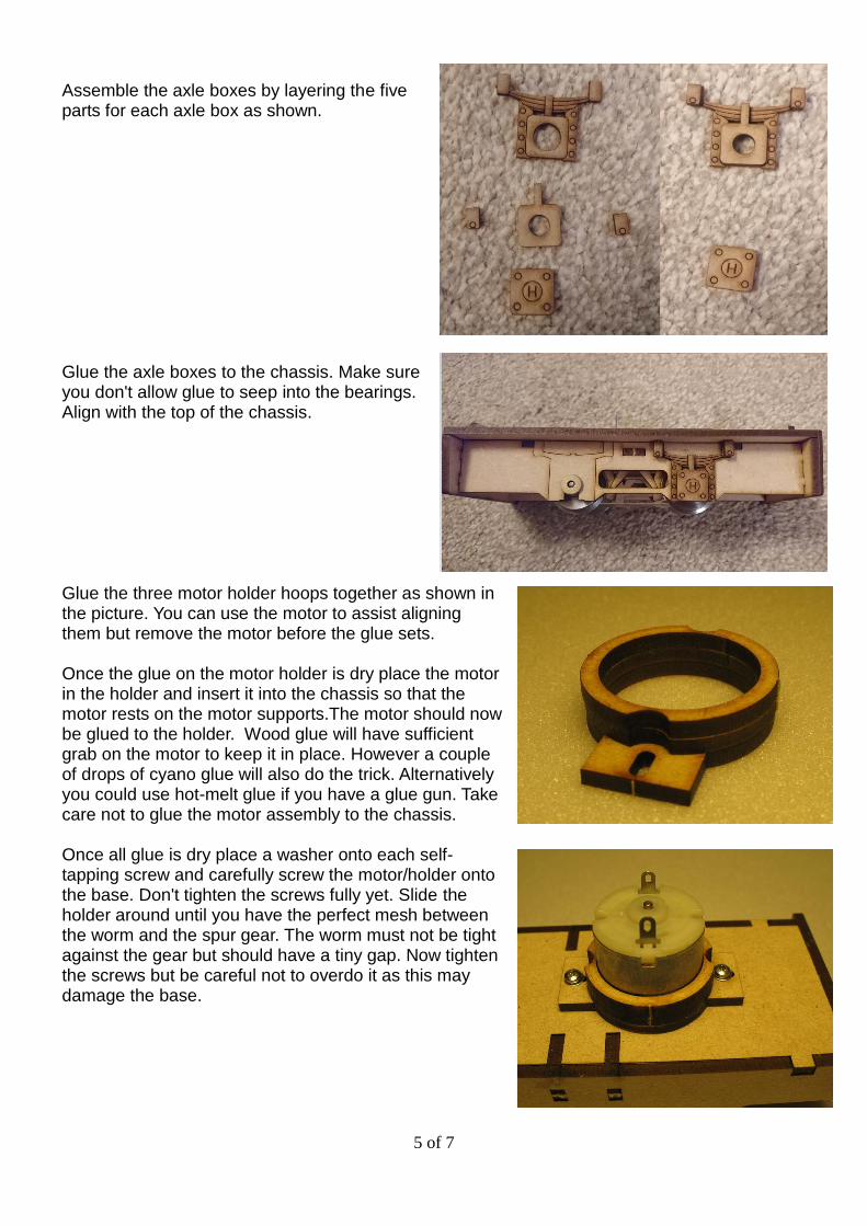
Assemble the axle boxes by layering the five parts for each axle box as shown. Glue the axle boxes to the chassis. Make sure you don't allow glue to seep into the bearings. Align with the top of the chassis. Glue the three motor holder hoops together as shown in the picture. You can use the motor to assist aligning them but remove the motor before the glue sets. Once the glue on the motor holder is dry place the motor in the holder and insert it into the chassis so that the motor rests on the motor supports.The motor should now be glued to the holder. Wood glue will have sufficient grab on the motor to keep it in place. However a couple of drops of cyano glue will also do the trick. Alternatively you could use hot-melt glue if you have a glue gun. Take care not to glue the motor assembly to the chassis. Once all glue is dry place a washer onto each self-tapping screw and carefully screw the motor/holder onto the base. Don't tighten the screws fully yet. Slide the holder around until you have the perfect mesh between the worm and the spur gear. The worm must not be tight against the gear but should have a tiny gap. Now tighten the screws but be careful not to overdo it as this may damage the base.

6 of 7
Fit the dummy adhesion weights to the chassis behind the buffer beam. You can use either one or two in each corner The chassis is now fully assembled, just add the batteries and switch to complete. If using this chassis with our Gordon loco body the switch fits in a hole in the cab front wall. The body is designed to be a friction fit onto the chassis between the body locators. When wiring the switch follow this circuit diagram. Be careful not to overheat the switch or motor when soldering the wires. The best advice is to use a really hot soldering iron and solder that contains flux to briefly touch the iron onto the joint to melt the solder and remove it before melting the surrounding plastic. Switches and motors are tested before dispatch.
Completed chassis pictured under the prototype Gordon loco

7 of 7
Troubleshooting. If the nylon worm gear wears very quickly it is usually down to one of two things:
Ensure that the nylon gear is central to the brass gear when running in both directions and adjust if necessary. A 0.6mm hex key is required to adjust the brass gear
When assembled correctly there will be a minimum amount of end float of the wheelset. If you accidentally omitted the washers on the axle you will have excessive end float and the nylon gear will wear out very quickly. In which case contact our technical department at [email protected]
The gears are meshed too closely. Slacken off the motor mount screws and back off the motor a little, then re-tighten and test again.
If motor does not run:
Ensure you have fresh batteries in place
Check all wiring for bad or dry solder joints
Does the switch click positively in both directions? If not the switch may have been overheated when soldering, contact the technical department for replacement [email protected]
Temporarily connect the motor direct to the batteries without the switch, if it runs recheck all wiring and if necessary replace the switch (See above), if it still does not run, contact the technical department for replacement [email protected]
We hope you enjoyed building this kit and that it provides many hours of entertainment for you. Why not send us a picture or two to us at [email protected] . We really love to see and share your photos.