Housing gr
32
Graduate Report - 2011 Urban Housing ( C E – 633 ) Planning Procedure for Different Unit ( Elaborate Procedure for Single Unit ) Prepared By – Shroff Cheitali ROLLNO. UP11023 Faculty Advisor – Dr. K.A.Chauhan PG In Charge – Dr. J. E. M. Macwan P. G. in Urban Planning , M. Tech. , Semester – 1 C E D , SVNIT , SURAT
-
date post
21-Oct-2014 -
Category
Engineering
-
view
56 -
download
1
description
How to design a unit
Transcript of Housing gr

Graduate Report - 2011
Urban Housing ( C E – 633 )
Planning Procedure for Different Unit( Elaborate Procedure for Single Unit )
Prepared By – Shroff CheitaliROLLNO. UP11023
Faculty Advisor – Dr. K.A.ChauhanPG In Charge – Dr. J. E. M. Macwan
P. G. in Urban Planning , M. Tech. , Semester – 1C E D , SVNIT , SURAT

INDEX
1. Introduction -Architectural Systems 2. Design Process3. Standard – Norms for EWS,LIG, MIG and HIG4. EWS , LIG, Vambay Units Design in Surat5. Transit Unit Design in Mumbai6. HIG Unit Design – Tata Piramanti in Gurgaon7. Luxury 3 / 4 BHK Apartment
Reference

The Architecture of Experienced Through Achieved by means of Accommodating a Compatible with its
SpaceStructureEnclosure Movement inSpace-Time Technology Program Context
Organizational pattern, Relationships, Clarity, Hierarchy Formal image and types of structureQualities of shapes, Colour, Texture, Scale, ProportionQualities of surfaces, Edges, and Openings Approach and EntryPath Configuration and AccessSequence of spacesLight, View, Touch, Hearing and Smell Structure and EnclosureEnvironmental protection and comfortHealth, and SafetyDurability and Sustainability User requirements, Needs, AspirationsSociocultural FactorsEconomic FactorsLegal ConstraintsHistorical Tradition Site and EnvironmentClimate: Sun, Wind, Temperature, PrecipitationGeography: Soils, Topography, Vegetation, WaterSensory and Cultural characteristics of the place
ARCHITECTURAL SYSTEMS

Design Process Design as a process is choosing the best solution out of several divisions/alters of designed solutions.It is an endless repetitive cycle. The Design Process mainly includes five stages as follows:BASIC means
Commit1 B Brief Data - Client Needs ( Who, What, When, Where, How, Why )
Collection of Information
2 A Analyze Hypotheses - Activity Chart and Bubble Diagram
3 S Synthesis Concept Development, Check, Compare, Decide
4 I Implementation Reevaluation , Finalize Design, Check for Regulation
5 C Communication Architect / PlannerClient , Structure Engineer, Govt.Bodies, Contractor, Market

PROJECT (Unit Level Planning) EXAMPLE – BUNGALOW FORMDESIGN PROBLEMIt is proposed to construct a bungalow for HIG Income Group. It should contain small office to accommodate 5 to 6 persons with separate entry, attached to building. Dining Room required separately ( Don’t Attach with Living or Kitchen) Parking required } 2 no’s Car and 2 no’s Two WheelerCalculate the site dimensions, assume general family particulars and design the same consider the following technical details.
Area requirement Total floor area = 250 +- 15% (sq m)Design particulars Load bearing wall system,(gr +1) Black cotton soil in foundation up to 1.2m depth The site is in humid region , the summer breeze is from
South-West The average annual rainfalls 100cmDesign Control Data Max. F.S.I. allowed – 1.8 Max. ground coverage allowed – 50% Plot width/depth ratio – 1.3 to 1.5 Min, margins: front – 4.5m; rear and side – 3mOther Data CONSIDER family size -6 persons
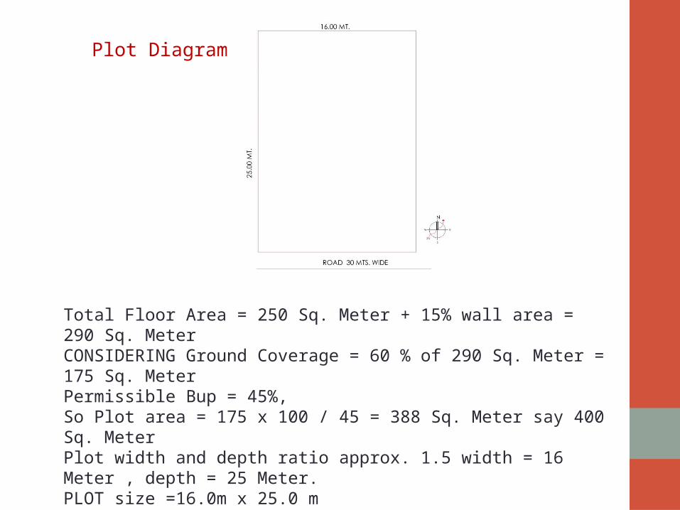
Plot Diagram
Total Floor Area = 250 Sq. Meter + 15% wall area = 290 Sq. MeterCONSIDERING Ground Coverage = 60 % of 290 Sq. Meter = 175 Sq. MeterPermissible Bup = 45%, So Plot area = 175 x 100 / 45 = 388 Sq. Meter say 400 Sq. MeterPlot width and depth ratio approx. 1.5 width = 16 Meter , depth = 25 Meter.PLOT size =16.0m x 25.0 m

STAGE 1 – BRIEF Commit The first stage in any design process is the commitment of the designer to the client that the design is ready as per the clients requirements & needs. The design should have solutions that are cost effective, innovative and functional while maintaining the goals and expectation of clients.
Data - Client Needs ( Who, What, When , Where , How, Why)The designer then prepares a design statement, also called the design brief, describing a particular set of circumstance, which creates a need. The brief outlines the needs related to the design problem. STATEMENT: Based on client’s requirement, needs and ideas, designer prepare a design brief to understand the unique characteristics of particular client and to use these aspects to best advantages. Often the character of a particular project is developed in response to the local surroundings.

CollectThe next step is the collection of information relating to the existing circumstances of the project. It is very important for the designer to understand the requirements of the client, therefore it is imperative that all the available information regarding the design outcomes are collected and studied carefully. The design constrains such as available time and resources and budget are also taken into account.
The various methods of collecting data are:Interview and user QuestionnaireLiterature researchGroup / Individual discussion with each and every member Interview and User QuestionnaireFamily size and age:Officer XXXXOfficer’s wife XXXXGrand Mother XXXXGrand Father XXXXDaughter XXXXSon XXXX

• How long do you expect to stay in this house• Any planning for future expansion of the house• Is there anything particular that you have seen in a house design or in
someone else’s house that you like• Any Specific Material , Colour , Texture feels good• Kind of Garden, Verandahs, Terrace, Balconies, they like• Special Rooms like Activity , Study , Hobby, Puja Room, Walk in Wardrobe
they needs• Kinds of Landscapes such as water body , rock garden, vegetable garden • Provision of Audio Visual, Home Theatre Room, • Provision for Servant Quarter • Do you like modern style bungalow or tradional style• What does your home means to you; aesthetics, security, comfort,
independence, privacy• Does anyone work at home; who and what kind of work• What kinds of Guest and how often they visit to you• What kind of family functions take place. • Who spents maximum time in the house?• Who’s going to maintain the house?

Literature study• Architect has to study the Latest design and technology in current
market• Site study• Case study at global level• National guideline manual• Similar Field project• Corporate projects• Rule and Regulation by corporation
Stage -2 Analyze The ability to define and understand the nature of the design problem adequately ,completely is an essential part of the solution.
Define the problem understand set Goals &objectives Of Design
As we cycle through the design process, a clearer understanding of a problem should emerge, new information may be uncovered to be required which could alter our preparation of the problem and its solution. The analysis of a problem, therefore, often continues throughout the design process.Prepare the activity chart after collecting all the datas, so as to start with design process.

Person
Activity Room
Allocation of Area
OwnerWelcomes to GuestSpend time in livingMeets Driver, Office Person, PeonRequire Separate Office
Otta Living RoomFoyerOfficeToiletOtta
6 to 10 Sq. Meter20 to 25 Sq.Meter6 to 8 Sq. Meter15 to 18 Sq. Meter1.5 to 2Sq. Meter6 to 8 Sq. Meter
Owner’s WifeCooking and Home Management
KitchenStorewashMaster BedroomToiletBalcony
9to 12 Sq. Meter5 to 7 Sq. Meter4 to 5 Sq. Meter15 to 18 Sq. Meter3 to 4 Sq. Meter5 to 7 Sq. Meter
Grand Father and Mother
BedroomToiletverandah
12 Sq. Meter2 to 3 Sq. Meter5 to 7 sq.mt.

Son
BedroomToiletBalcony
10 to 12 Sq. Meter2 to 3 Sq. Meter5 to 7 sq.mt.
Guest
BedroomToilet
10 to 12 Sq. Meter2 to 3 Sq. Meter
Common Area
DiningToiletStaircaseTerrace
8 to 10 Sq. Meter2 to 3 Sq. Meter8 to 10 Sq. Meter12 to 15 Sq. Meter
Total carpet areaAdd circulation space 10%TotalAdd wall area as 15%
234 Sq. Meter 23 Sq. Meter257 Sq. Meter 39 Sq. Meter
Total required floor area 296 Sq. Meter aprox.Common open spaces Parking
GardenBackyard
30 to 40 Sq. Meter50 Sq. Meter18 to 20 Sq. Meter
Total min. required plot area
406 Sq. Meter aprox.

After collecting the data & activity areas, the lay out process is to be started
• The layout should be started with Organizational relationships, i.e. the lay out of different activities, areas or zoning of space by bubble diagram.
• Bubble diagrams: it graphically illustrates function and spatial relationships of different areas
• Prepare 4 to 5 bubble diagrams keeping in mind weather conditions, site conditions & room activities.
• If the bubble diagram is satisfactory check for grouping of different activities. • Assign values to key elements i.e. the location of important rooms, Weather protection, health, safety, and welfare of occupants (e.g. structural soundness, environmental comfort, electrical & drainage system performance)• Contextual: cultural, historical, religious, political context; relationship of
external systems such as power sources, communication, water, transportation should also be considered.
• Economics: relationship to client’s budget; life-cycle costs, quality and quantity, expectations v/s reality.

Stage -3 - Synthesis Form the analysis of the problem and its parts; we can begin to formulate possible solutions. This requires synthesizing – bringing together integrating – responses to the various issues and aspects of the problem into coherent solutions.
Concept Development Once the data relating to the design problem has been collected and analyzed, the designer can being to formulate the first idea of design solution. There are number of techniques which can help the designer in the process, such as: • Role playing: in this process the designer can think from the point of view
of the client or people who will be using that space by putting himself/herself in the client’s space.
• Brainstorming: this is a very careful method as it allows the designer to
come up with diverse ideas for the design solution. • Group discussion: a number of group ideas are likely to emerge during a
group discussion, as each individual will put forward his/her own solution and from these the most suitable can be chosen.

Develop schematic designs from final bubble diagrams checks for following principle • Orientation – ClimatologyMaximum use of nature is to be consider for light and ventilation of each and every room to make it energy efficient building.Follow solar path and place your rooms accordingly• GroupingCheck the grouping of different activities area and service areas • Circulation Check the circulation pattern between connecting activities, with minimum wastage of space& minimum areas.• Internal and External Privacy Passages should be such that each area maintain its privacy • Flexibility Area of Rooms or Activity Areas can be altered • ServicesDrainage, Water Supply, Electricity shall be design for ease of maintenance and cleanliness with minimum running cost


Compare Alternatives & Make Decisions Compare each alternative with design goals.Weigh the benefits and strength, weakness of each one against cost, safety, aesthetic, nature, climate suitability and effectiveness Hoew to choose the best solution- • Personal choice: The client or a user dictates the choice of design solution.• Critical comparison: two or more design solutions are compared on the
basis of their qualities and out of this, one best suited is picked. Once the choice has been made, the process of making preliminary drawings can begin. A preliminary plan of a design solution will have• Sealed proportion of spaces and elements• Prepare single line diagram for both the floors and present it to client for
feedback and preliminary approval • Additional of internal architectural details• Walls, windows and built up items are shown• Furniture might be indicated in some areas• Checks for buildings regulation and guidelines applied with governing
statutory authorities.• Make preliminary material selection with Colour schemes to work out the
temporary budget of the project.

Stage 4 - Implementation Once a final decision has been made, the design proposal is developed, refined and prepared for implementation. This includes the production of working drawing and specifications, and other services related to purchasing, construction and supervision Reevaluation • Before implementation architect should once again weigh the
solution with alternates prepared by him that is thhese the best finally?
• Design requires a critical review of alternatives and careful weighing of the strengths and weaknesses of such problems of such proposal until its best possible fit between problem and solution is achieved.
• Non design process is a complete until a design solution which has been implemented is evaluated for its effectiveness in solving a given problem.
• In the design process there is always more than one valid solution to a design problem. So How then can we judge whether a design is good or bad?

A design may be good, in the judgment of the designer, the client, or the people who experience and use the design, for any of several reasonA design may be good because it functions well – it worksA design may be good because it is affordable – it is economical, efficient&durableA design may be good because it looks good – it is aesthetically pleasingAt times we may judge a design to be good because we feel it follows current design trends – it is in fashion-or because of impression it will make on others – it enhances our status. A good design, should be understandable.
If a design does not express an idea, communicate a meaning, or elicit a response. Either it will be ignored or it will be a bad design.
Process of Measuring Design Solution Function and Purpose- the intended function of the design must be satisfied and fulfilled. Utility and Economy-a design should exhibit utility, honesty and economy in its selection and use of materials. Form and Style- the design should be aesthetically pleasing to the eye and our other senses. Image and Meaning- The design should project an image and promote association that carry meaning for the people who use and experience it.

Stage 5 - Communication The architect plays key role in the project execution. He /she has to play varied role in the design process from start to end• After finalizing the design he has to appoint structural engineer.• He has to submit the necessary documents & plans to local government for
passing the proposal & maintain the record/track till obtaining the buc as well as water & electrical connections.
• He has to prepare the estimate for the bank loan if required by client.• At the same time he has to finalize the contractor & obtain the Quotations
for the proposal so as to meet the client’s budget.• Before executing the work on site he should check the site correctly &
modify any misleading data in design • He should prepare all the floor plans with all the necessary services shown
in the drawings.The sets of drawings includes- Site lay out plan, Setting out plan Centerline plan , working drawing of all floors i.e ground to terrace floor Elevations all sides, sections as necessary- passing thru toilet & staircase must Door ,window, toilet & any other detail drawings Drainage layout, Electrical layouts

Drawings by structural engineer Foundation& footing plan Ground beam & plinth beam plan First floor slab beam plan Terrace slab beam plan Any other specific detail
• During execution He has to visit the site regularly so a s to communicate
with client to inform about the site progress, contractors quality of work, & amount of work done
• He has to communicate between structural engineer & contractor so as to provide him necessary plans as required to save the time. & avoid any construction mistakes during execution.
• After completion of building he has to resubmit the plans to authorities to obtain buc.

Category Monthly Income limit Areas allotted
BPL HOUSING SCHEME BELOW 2,500 15 TO 20 sq.mts.
Economically Weaker Section (EWS)
Upto Rs. 3,300/- 22.45 sq.mts.
Lower Income Group (LIG) Rs. 3,301 to Rs. 7,300 38.00 sq.mt.
Middle Income Group (MIG) Rs. 7,301 to Rs. 14,500 55.00 sq.mt.
Higher Income Group (HIG) More than Rs. 14,500/- 50 to 100& above
Gujarat Housing Board constructs houses for people of various income categories as per norms set by the State Government as detailed below.
Norms of EWS,LIG,MIG,HIG

Typical floor plan consisting four dwelling units on each floor. The building block is ground plus three-storied R.C.C. framed structure.
EWS HOUSING SCHEMES

Description Detail Room areas
Living Room 2.60 M x 2.75 M 7.15 SQ.MT.
Kitchen 2.00 M x 1.80 M3.60 SQ.MT.
W.C. 0.98 M x 0.90 M0.882 SQ.MT.
Chokdi 0.90 M x 0.90 M 0.81 SQ.MT.
Balcony 1.05 M Wide
Total Built-up area 22.45 Sq. Mtr.
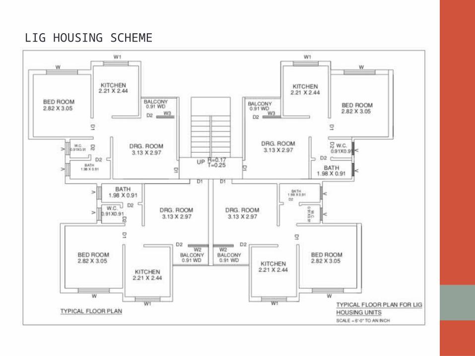
LIG HOUSING SCHEME

Description Detail Carpet Areas
Living Room 3.13 M x 2.97 M 9.29 SQ.MT.
Kitchen 2.21 M x 2.44 M 5.39 SQ.MT.
Bed Room 2.82 M x 3.05 M 8.60 SQ.MT.
W.C. 0.91 M x 0.91 M 0.82 SQ.MT.
Bath 1.98 M x 0.91 M 1.80 SQ.MT.
Passage 1.00 M x 0.91 M 0.91 SQ.MT.
Balcony 0.91 M x 2.00 M 1.82 SQ.MT.
Total Built-up area 38.00 SQ. MT.

VALMIKI - AMBEDKAR AWAS YOJANA (BPL Housing)
TYPE - I : Raw HousesBuilt up area: 20.16smt (Govt. has recommended 15 smt.)
Description DetailCarpet Areas
Room 3.05 M x 3.66 M11.16 SQ.MT.
Toilet 1.80 M x 1.08 M 1.94 SQ.MT.
Wada 1.08 M x 1.05 M 1.13 SQ.MT.
Otta 0.90 M x 3.05 M 2.74 SQ.MT.
Total Built-up area 20.16 SQ. MT.
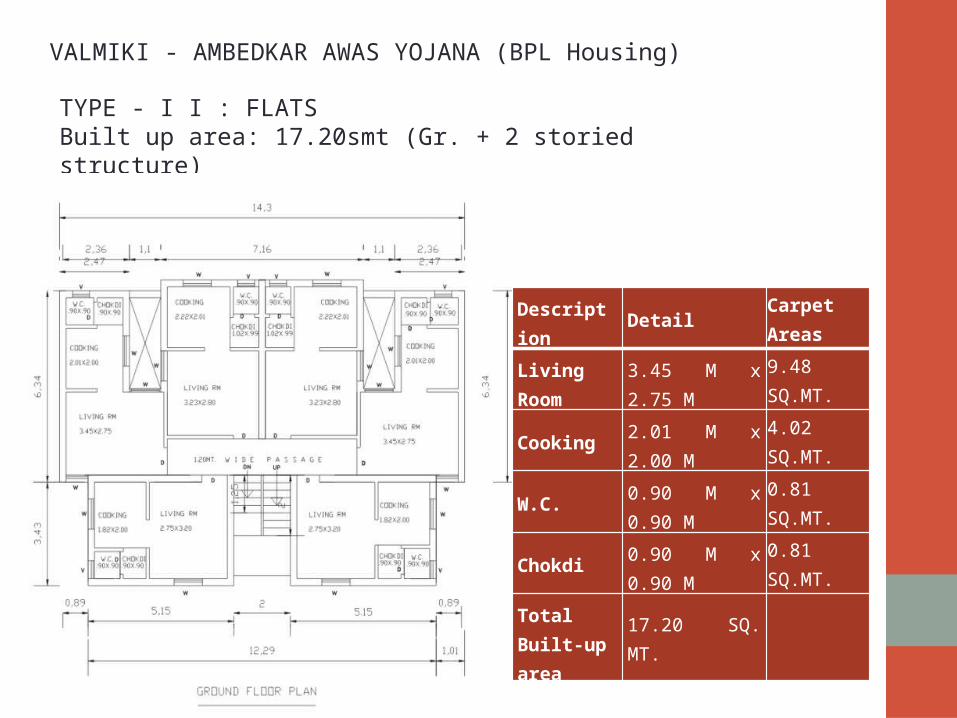
VALMIKI - AMBEDKAR AWAS YOJANA (BPL Housing)
TYPE - I I : FLATSBuilt up area: 17.20smt (Gr. + 2 storied structure)
Description Detail Carpet Areas
Living Room 3.45 M x 2.75 M 9.48 SQ.MT.
Cooking 2.01 M x 2.00 M 4.02 SQ.MT.
W.C. 0.90 M x 0.90 M 0.81 SQ.MT.
Chokdi 0.90 M x 0.90 M 0.81 SQ.MT.
Total Built-up area 17.20 SQ. MT.
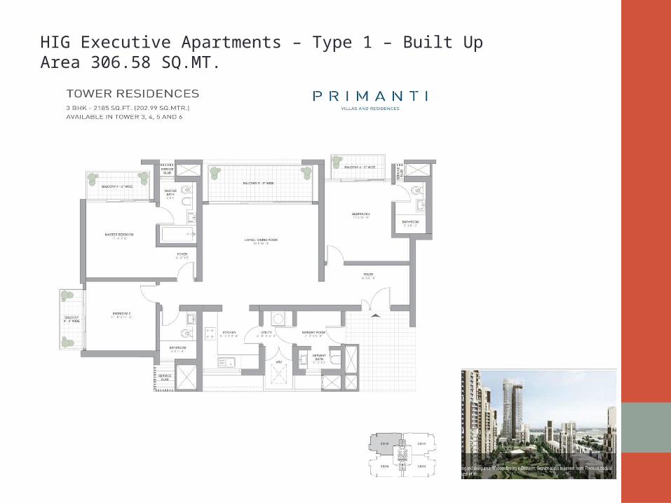
HIG Executive Apartments – Type 1 – Built Up Area 306.58 SQ.MT.

Description Detail Carpet Areas
Living Room 5.50 M x 5.10 M 28.05 SQ.MT.
Dining 3.50 M x 2.74 M 9.59 SQ.MT.
Kitchen 3.65 M x 2.82 M 10.29 SQ.MT.
Balcony 1.25 M x 7.74 M 9.67 SQ.MT.
Master Bed Room 4.57 M x 3.88 M 17.73 SQ.MT.
Toilet 2.05 M x 2.59 M 5.30 SQ.MT.
Balcony 1.02 M x 3.00 M 3.60 SQ.MT.
Bed Room – 2 3.42 M x 3.35 M 11.45 SQ.MT.
Toilet 2.28 M x 1.62 M 3.69 SQ.MT.
Balcony 1.02 M x 3.00 M 3.60 SQ.MT.
Bed Room – 3 3.42 M x 3.35 M 11.45 SQ.MT.
Toilet 2.28 M x 1.62 M 3.69 SQ.MT.
Bed Room – 4 3.96 M x 3.88 M 15.36 SQ.MT.
Toilet 2.05 M x 2.59 M 5.30 SQ.MT.
Balcony 1.02 M x 3.00 M 3.60 SQ.MT.
Foyer 3.88 M x 2.97 M 11.52 SQ.MT.
Passage 1.20 M x 4.00 M 4.80 SQ.MT.
Servant Room 2.05 M x 2.83 M 5.80 SQ.MT.
Toilet 1.30 M x 1.67 M 2.17 SQ.MT.
Store 1.50 M x 1.50 M 2.25 SQ.MT.
Total Built-up area 306.58 SQ. MT.

TEXT BOOKS• Ching Binggeli , (1943). “Interior Design Illustrated”, published by John
Wiley and Sons, Inc., Hoboken, New Jersey.
WEBLIOGRAPHY• Www.Mhada.Bom.Nic.In/html/web_vambay.Htm• Www.Suratmunicipal.Com• Www.Tatapiramati.Com
REFERENCES

Thank You


![CHHATTISGARH HOUSING BOARD RAIPUR [CG.] - … 720 LIG FLATS (GR...[1] ATAL VIHAR YOJNA CHHATTISGARH HOUSING BOARD CHHATTISGARH HOUSING BOARD RAIPUR [CG.] NOTICE INVITING TENDER For](https://static.fdocuments.in/doc/165x107/5ad275ff7f8b9a72118d2d8f/chhattisgarh-housing-board-raipur-cg-720-lig-flats-gr1-atal-vihar.jpg)