BOARD OF COMMISSIONERS TRAINING U. S. Dept of Housing and Urban Development Financial Management

HOUSING & DEVELOPMENT
BOARD
PRECAST PICTORIAL GUIDE 2014

© HOUSING & DEVELOPMENT BOARD 2014. NO PART OF THIS PUBLICATION MAY BE REPRODUCED OR TRANSMITTED IN ANY FORM OR BY ANY MEANS, OR STORED IN ANY RETRIEVAL SYSTEM OF ANY NATURE, WHETHER ELECTRONIC OR MECHANICAL, INCLUDING PHOTOCOPYING AND RECORDING, WITHOUT THE PRIOR WRITTEN PERMISSION OF HDB. THESE GUIDES WERE DEVELOPED FOR HDB’S OWN USE ONLY. HDB SHALL IN NO WAY BE LIABLE FOR ANY LOSS (WHETHER DIRECT, INDIRECT OR CONSEQUENTIAL LOSS INCLUDING PURE ECONOMIC LOSS) TO ANY PERSON RELYING ON ANY OF THE CONTENTS, WHETHER WHOLLY OR PARTIALLY, OF THIS PUBLICATION. HDB DOES NOT WARRANT OR REPRESENT THAT THESE GUIDES ARE SUITABLE FOR ANY PURPOSE NOR THAT THEY ARE ACCURATE OR UP-TO-DATE. ANY PERSONS WHO REFER TO OR ADOPT, WHETHER WHOLLY OR PARTIALLY, THE CONTENTS OF THIS PUBLICATION SHALL NOT BE RELIEVED OF ANY PROFESSIONAL AND CONTRACTUAL RESPONSIBILITIES. THESE RESPONSIBILITIES INCLUDE BUT ARE NOT LIMITED TO: (I) VERIFYING THE ACCURACY OF THE CONTENTS OF THIS PUBLICATION; (II) CORRECTLY APPLYING THE CONTENTS OF THIS PUBLICATION; (III) OBTAINING ALL RELEVANT PROFESSIONAL ADVICE AND SERVICES; AND
(IV) CONSIDERING THE CONTENTS OF THIS PUBLICATION IN CONJUNCTION WITH ALL OTHER RELEVANT REQUIREMENTS, DOCUMENTS OR INFORMATION
NECESSARY FOR THE SPECIFIC REQUIREMENTS OF THEIR PROJECT.

TABLE OF CONTENTS
LIST OF FIGURES
CHAPTER 1 TO GET YOU STARTED 1
CHAPTER 2 UNIT 5
CHAPTER 3 COMMON AREA 12
CHAPTER 4 JOINTS & CONNECTION DETAILS 18
CHAPTER 5 PRECAST COMPONENTS 24
ANNEX A FREQUENTLY ASKED QUESTIONS
ANNEX B STANDARDISATION & PRECAST COMPONENT
CATEGORIES
ANNEX C THE RATIONALE BEHIND 100 REPETITIONS AND HOW
TO APPROACH THIS NUMBER
ANNEX D POINTS TO NOTE WHEN HAVING GROOVELINES
ANNEX E ANALYSIS AND EXPLANATION WITH EXAMPLE TO
ACCOMMODATE STANDARD PRECAST STAIRCASE FLIGHT
ANNEX F HDB’S WATERPROOFING SYSTEM
List of figures
Fig 1A Typical floor-to-floor height
Fig 1B 14mm vertical joint
Fig 1C 15mm or 20mm horizontal joint
Fig 2A Typical storey residential floor part plan 1 – with thickness indicated
Fig 2B Typical storey residential floor part plan 2 – joints and components
Fig 2C L-shaped façade
Fig 2D Corner window façade
Fig 2E Concrete framing for cast-in window frame
Fig 2F Minimum 100mm overhang canopies
Fig 2G Types of acceptable and non-acceptable canopies
Fig 2H Canopy length and profile
Fig 2I Standard coping detail
Fig 2J Coping profile for KP at service yard
Fig 3A Staircase dimensions stipulated in guide drawings
Fig 3B Protrusion of lift wall to be non-structural
Fig 3C Dimensions of refuse or recyclable chutes
Fig 3D No integration of chutes with other components
Fig 3E Only C-shape, E-shape or F-shape ducts shall be adopted
Fig 3F Types of segments for water tank design
Fig 3G Mixing and matching segments to achieve different configurations and
capacities
Fig 3H Maximum water level and design load for different types of water tanks
Fig 3I Termination of canopy at edge of column
Fig 3J Use of different plank types at MSCP
Fig 4A Open drain at horizontal joint
Fig 4B Vertical connection details for precast wall
Fig 4C Vertical connection details between precast wall/column and precast façade
Fig 4D Vertical connection details for half-height precast façade (K3F / K4F)
Fig 4E Horizontal connection details for precast wall and column
Fig 4F Horizontal connection details for precast façade

Fig 4G Façade acting as non-structural column clad must be 120mm thick
Fig 5A Typical details of 2-tier precast column (sectional view)
Fig 5B Non-structural vertical components shall not protrude out of building line by
more than 600mm
Fig 5C Pre-fabricated cages for columns and meshes for walls & household shelters
Fig 5D Use of wet pour to avoid differential cambering
Fig 5E Precast component shall have no protruding bars
Fig A1 Kitchen wall component facing both internal and external
Fig A2 No aluminium sill required for CIW
Fig A3 Section through cast-in window frame showing 20mm water-stop all round
Fig A4 Component without 100 repetitions must be justified
Fig A5 Provision of 100mm thick fin for fire break
Fig A6 Fins without functional purposes shall not be provided
Fig A7 Canopies over windows shall have a minimum 100mm overhang
Fig A8 KP profile at corridor
Fig C1 Handed façade to be made the same or similar

Precast Pictorial Guide
Chapter 1 – To get you started
1
CHAPTER 1
TO GET YOU STARTED
1.1 Reinforcements shown in the pictorial guide are the minimum
reinforcement required and shall only serve as reference. The user of
this guide must check the adequacy of the reinforcements to meet their
design requirement.
1.2 For the nomenclature of the precast concrete components naming,
refer to Figure 2.A of Chapter 2.
1.3 For safety and durability, the elements at the peripheral of the building
line are to be precast. For standalone beams at 2nd storey, they shall
be constructed by the cast in-situ method. Precast beam shall be
adopted when they are integrated with precast façade such as K1F.
1.4 All components plus lifting frame (if required) shall not exceed 8 tonnes.
Consultants shall also check this weight against the tip load and the
specifications of the lifting equipment.
1.5 Floor-to-floor height is usually 3.6m from 1st to 2nd storey, and
typical floor-to-floor height shall be 2.8m. The floor-to-floor height of
the topmost floor (to the lowest point of roof) is also 2.8m.

Precast Pictorial Guide
Chapter 1 – To get you started
2
Figure 1A – Typical floor-to-floor height

Precast Pictorial Guide
Chapter 1 – To get you started
3
1.6 Precast components are categorised into 3 categories (refer to Annex B
for the components in each category):
Category 1: Precast components that can be standardised fully across
all projects.
Category 2: Precast components that can be standardised partially
across all projects.
Category 3: Precast components that can be standardised within
individual project.
1.7 At the connections for precast components, there exists a 14mm gap
for vertical joints.
Figure 1B – 14mm vertical joint
1.8 For horizontal joints between precast components, the joint is 15mm or
20mm (from structural floor level to joint).
Precast wall – 15mm horizontal joint Precast column – 20mm horizontal joint
Figure 1C – 15mm or 20mm horizontal joint

Precast Pictorial Guide
Chapter 1 – To get you started
4
1.9 Consultants are to use at least 100 repetitions as the guideline
for component repetition to ensure cost-effectiveness of the
project (Refer to Annex C – The rationale behind 100 repetitions
and the right way to approach this number).

Precast Pictorial Guide
Chapter 2 – Unit
5
CHAPTER 2
UNIT
2.1 Figure 2A shows a typical storey residential floor part plan, with
the thickness of the components in a unit indicated.
Figure 2A - Typical storey residential floor part plan 1 – with thickness
indicated

Precast Pictorial Guide
Chapter 2 – Unit
6
2.2 Figure 2B shows a typical storey residential floor part plan, with
facade connection joints (for joints detail refer to the guide
drawing – connection and waterproofing details for precast
façade/typical details of precast façade). The components within
a unit including planks panelling, with the standard
nomenclatures, are also indicated.
Figure 2B– Typical storey residential floor part plan 2 – Joints and
components

Precast Pictorial Guide
Chapter 2 – Unit
7
2.3 For precast façade integrated with beam, the façade thickness is part
of the beam width (See Fig. 4F in Chapter 4 for illustration).
2.4 The longest dimension of any parapet and façade shall be kept to a
maximum of 7m.
2.5 The shorter length of any L-turn façade including facade with corner
window (mullion to end of concrete framing) shall not exceed 1m. For
facade with corner window, the concrete frame of the window facade
shall be at least 200mm by 200mm (depend on wall or column size).
Figure 2C – L-shaped façade Figure 2D – Corner window facade

Precast Pictorial Guide
Chapter 2 – Unit
8
2.6 There shall be adequate concrete framing for cast-in windows
frame. A 300mm concrete framing is required for clad-over
and abutting connection.
Figure 2E – Concrete framing for cast-in window frame
2.7 Canopies over windows shall have a minimum 100mm overhang
(See Annex A – FAQ A5 for further information).
Figure 2F – Minimum 100mm overhang canopies
Window frame Window frame
Clad-over connection (left) and abutting connection (right)
Extend canopy
minimum 100mm
beyond both ends of
the window frame.

Precast Pictorial Guide
Chapter 2 – Unit
9
2.8 Window coping shall be minimally sized to both edge of the cast-in
window frame.
2.9 The design for canopy should be functional, simple to construct and
regular. i.e. there shall not be double, irregular, such as curved or
angled canopies (See Annex A – FAQ A6 for further information).
Figure 2G – Types of acceptable and non-acceptable canopies
2.10 Groove lines shall not be continuous across panels and must be kept at
least 25 / 100mm (See Annex D – Points to note when having
groovelines) from the edge of each component.
Design regular canopy shapes.
Irregular canopy shapes are non-acceptable.
Double canopies non-acceptable.

Precast Pictorial Guide
Chapter 2 – Unit
10
2.11 Canopy width (from external of facade wall to edge), shall be
kept at either 300mm or 600mm. For K1F facade, to adopt flat
soffit profile. For KP to adopt sloping soffit profile for 600mm
canopies.
Figure 2H – Canopy length and profile
2.12 Slope for canopies shall be standardised for the same length of
canopies.
2.13 Coping shall adopt the standard detail in the guide drawing.
Figure 2I – Standard coping detail
300mm canopies to adopt flat soffit profile. 600mm canopies to adopt sloping profile.

Precast Pictorial Guide
Chapter 2 – Unit
11
2.14 Coping for KP at service yard shall adopt the following profile :
Figure 2J – Coping profile for KP at service yard
Windows above No windows above

Precast Pictorial Guide
Chapter 3 – Common Area
12
CHAPTER 3
COMMON AREA
3.1 Items 2.3 to 2.5 & 2.9 to 2.13 in Chapter 2 – Unit, are also
applicable to the common area.
3.2 Staircase (residential and MSCP) dimensions must be as stipulated
in the design guide drawings – precast staircase.
Figure 3A – Staircase dimensions stipulated in guide drawings
To cater for finishing and screeding, 1st
riser of precast staircase to be 205mm, all
other risers shall be 175mm.
Typical staircase flight – 1st to 2nd storey Typical staircase flight – Typical floor-to-floor

Precast Pictorial Guide
Chapter 3 – Common Area
13
3.3 For floor height other than the typical 2.8m, adjustments to the
stairwell structural floor level (SFL) may be necessary to accommodate
the standard staircase risers, e.g. raise 50mm at first storey stairwell
SFL for 3.6m floor-to-floor height (See Annex E for detailed
explanation).
3.4 The 600mm protrusion of the lift wall shown in Figure 3B shall be non-
structural.
Figure 3B – Protrusion of lift wall to be non-structural
3.5 Precast refuse or recyclable chutes are to follow dimensions stipulated
in the guide drawings – Precast Refuse Chute.
Figure 3C – Dimensions of refuse or recyclable chutes

Precast Pictorial Guide
Chapter 3 – Common Area
14
3.6 Precast refuse or recyclable chutes shall be stand-alone and shall
not be integrated with other components.
Figure 3D – No integration of chutes with other components
3.7 Service ducts used for the same type of services shall be
standardised, and only C-shape, E-shape or F-shape ducts shall
be adopted.
Figure 3E – Only C-shape, E-shape or F-shape ducts shall be adopted
Odd-shaped duct
L-shaped duct
C and E-shaped ducts
F-shaped ducts
Legend
Precast refuse chute
Cantilever beams
1700
1000
1000
100
Fin
Improved design
Details 3 :
Removal of the cladding and adding fins to serve
as termination treatment for the cantilever beams
Precast Pictorial Guide
Chapter 3 – Common Area
15
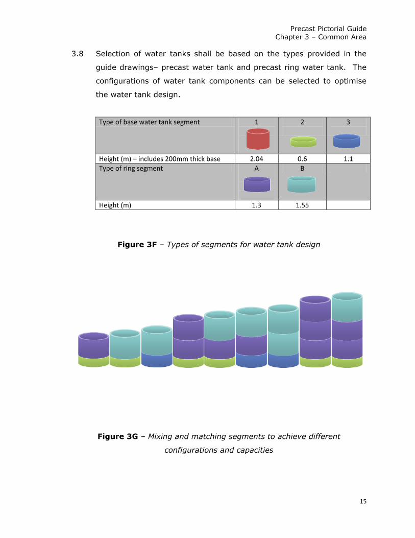
3.8 Selection of water tanks shall be based on the types provided in the
guide drawings– precast water tank and precast ring water tank. The
configurations of water tank components can be selected to optimise
the water tank design.
Type of base water tank segment 1
2
3
Height (m) – includes 200mm thick base 2.04 0.6 1.1
Type of ring segment A
B
Height (m) 1.3 1.55
Figure 3F – Types of segments for water tank design
Figure 3G – Mixing and matching segments to achieve different
configurations and capacities

Precast Pictorial Guide
Chapter 3 – Common Area
16
Standard Tank Domestic Tank
Sizing
With suction
tank
Without suction
tank 2-ring 3-ring 4-ring
Base types 1 1 2 2 3 3 2 2 2 3 3 2 2 2
Body segments types
NA NA A B A B 2A A+B 2B A+B 2B 3A 2A+B A+2B
Max water level from base (m)
1.5 1.43 1.27 1.52 1.77 2.02 2.57 2.82 3.07 3.32 3.57 3.87 4.12 4.37
Design Load (with tank cover and filled with
water) – kN
260 260 300 330 370 400 470 510 540 580 610 650 690 720
Figure 3H– Maximum water level and design load
for different types of water tanks
Note: For other C&S design considerations for water tank, consultants are to refer to section 19:
Reinforced concrete water tank of the C&S guide.
3.9 Canopies shall not pull around columns along access corridors, as
it will give rise to potential alignment issues. Canopy shall
terminate at the edge of the column.
Figure 3I – Termination of canopy at edge of column
Do not wrap around columns – possible misalignment issues

Precast Pictorial Guide
Chapter 3 – Common Area
17
3.10 The use of different plank types at the different locations of the MSCP,
are shown in the following typical deck floor plan. For more details,
consultants shall refer to the guide drawings – MSCP deck details.
Figure 3J– Use of different plank types at MSCP

Precast Pictorial Guide
Chapter 4 – Joints & connection details
18
CHAPTER 4
JOINTS & CONNECTION DETAILS
4.1 Horizontal joints shall be kept open so that water flowing through
the vertical joints is allowed to discharge. Typical details are
shown in the Figure 4A.
Figure 4A – Open drain at horizontal joint

Precast Pictorial Guide
Chapter 4 – Joints & connection details
19
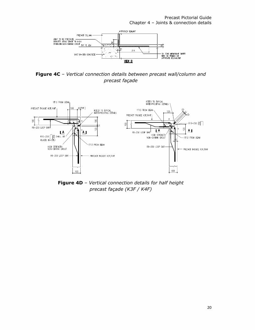
4.2 Figures 4B to 4D illustrates the different types of vertical connection
details.
Figure 4B – Vertical connection details for precast wall
Precast Pictorial Guide
Chapter 4 – Joints & connection details
20
Figure 4C – Vertical connection details between precast wall/column and
precast façade
Figure 4D – Vertical connection details for half height
precast façade (K3F / K4F)

Precast Pictorial Guide
Chapter 4 – Joints & connection details
21
4.3 Figures 4E and 4F illustrates the different types of horizontal joint
details between precast components.
Figure 4E – Horizontal connection details for precast wall and column

Precast Pictorial Guide
Chapter 4 – Joints & connection details
22
Figure 4F – Horizontal connection details for precast façade

Precast Pictorial Guide
Chapter 4 – Joints & connection details
23
4.4 Step-joint detail shall be used for 150mm thick façade (see joint ‘a’ of
Fig 4F).
4.5 Sloping detail shall be used for 100mm thick K1HF façade at toilet
(see joint ‘b’ of Fig 4F).
4.6 Façade shall be flushed to the external face of the beam (shown in type
JF1 and type JF6 in Fig 4F).
4.7 Façade acting as column non-structural clads must be 120mm thick such
that step-joint profile can be adopted. For non-structural column clads,
an open drain must be maintained.
Figure 4G – Façade acting as non-structural column clad must be
120mm thick

Precast Pictorial Guide
Chapter 5 – Precast components
24
CHAPTER 5
PRECAST COMPONENTS
5.1 Precast columns shall be 2-tier if it is not integrated with other
components. 3-tier columns shall not be employed unless specifically
design to address the handling stress during erection.
5.2 Typical details of the 2-tier column are shown in Figure 5A.
Figure 5A – Typical details of 2-tier precast column (sectional view)

Precast Pictorial Guide
Chapter 5 – Precast components
25
5.3 Columns are to be integrated with gable-end wall to form a plane
element (PC-KGW with column 1-tier). The base of the gable-end wall for the
integrated component shall also be pressure grouted. Consultants are
reminded to check the weight of the integrated component against the tip
load and the specifications of the lifting equipment.
5.4 External structural vertical components shall not protrude out of the building
line. For non-structural vertical components protruding out of the building line,
the protrusion shall not be more than 600mm. This is to achieve a safe
working environment during installation.
Figure 5B – Non-structural vertical components shall not protrude out
of building line by more than 600mm
Living/Dining Living/Dining
Living/Dining Living/Dining
Precast Pictorial Guide
Chapter 5 – Precast components
26
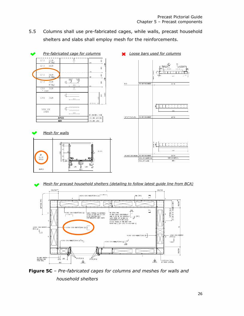
5.5 Columns shall use pre-fabricated cages, while walls, precast household
shelters and slabs shall employ mesh for the reinforcements.
Pre-fabricated cage for columns Loose bars used for columns
Mesh for walls
Mesh for precast household shelters (detailing to follow latest guide line from BCA)
Figure 5C – Pre-fabricated cages for columns and meshes for walls and
household shelters
Precast Pictorial Guide
Chapter 5 – Precast components
27
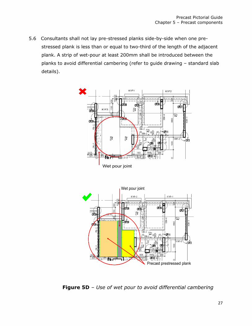
5.6 Consultants shall not lay pre-stressed planks side-by-side when one pre-
stressed plank is less than or equal to two-third of the length of the adjacent
plank. A strip of wet-pour at least 200mm shall be introduced between the
planks to avoid differential cambering (refer to guide drawing – standard slab
details).
Figure 5D – Use of wet pour to avoid differential cambering

Precast Pictorial Guide
Chapter 5 – Precast components
28
5.7 In general, all reinforcements shall be contained within the dimension
of the precast components. There shall not be any bars protruding out
from the precast component, which will cause obstruction during
installation.
Figure 5E – Precast component shall have no protruding bars

Precast Pictorial Guide
Annex A
A-1
Annex A – Frequently Asked Questions
A1. I have a layout as below (see Fig. A1). The kitchen wall
component has portions facing both internal and external. What type
of joint should I adopt?
For kitchen wall component which has portions facing both internal and
external, step joint shall be adopted (Joint ‘a’ in Figure 4F). An in-situ kerb
shall be constructed to fit the step joint of the portion facing internal.
Figure A1 – Kitchen wall component facing both internal and external

Precast Pictorial Guide
Annex A
A-2
A2. Is aluminium sill required for cast-in window (CIW)?
No aluminium sill is required for CIW.
Figure A2 – No aluminium sill required for CIW
However, there should be a 20mm water-stop all round for CIW at
external face.
Figure A3 – Section through cast-in window frame showing
20mm water-stop all round

Precast Pictorial Guide
Annex A
A-3
A3. I have some precast components which I am unable to meet the
100 repetition guide. What should I do about it?
The precast component repetition schedule shall be submitted as early as
possible to the precast review team. If the repetition falls under 100 because
of architectural treatment of the façade, the consultants would be required to
study and revise their design.
Figure A4 – Component without 100 repetitions must be justified

Precast Pictorial Guide
Annex A
A-4
A4. My project layout requires fins to be provided at service
yards and air-con ledge due to security, are there any issues
with that?
We have no issues with provision of fins at service yards and air-con
ledge, as long as the fins are solely for functional purposes (e.g.
security or fire break) and shall be 100mm thick.
Figure A5 – Provision of 100mm thick fin for fire break
Figure A6 – Fins without functional purposes shall not be provided

Precast Pictorial Guide
Annex A
A-5
A5. Item 2.8 states that canopies over windows shall have a
minimum 100mm overhang. Can the canopies ends at the edge
of the window frame?
No. 100mm minimum is required for the water drip line to be effective, to
minimise wind driven rain to enter through the window.
Figure A7 – Canopies over windows shall have a minimum 100mm overhang
A6. I need to make use of the canopy to accentuate my
architectural design intent. Item 2.10 states that canopies are for
functional purposes, are there any exceptions to this?
Canopies are solely for functional purposes, in the event where it is absolutely
necessary to be modified to enhance the architectural design, it will be dealt
with on a case-by-case basis.
However, consultants shall note that, by modifying the canopy, it would not
be allowed if it adversely affects the precastability of the component (e.g.
double canopy). It would also not be allowed if the consultants are unable to
meet the 100 component repetition.

Precast Pictorial Guide
Annex A
A-6
A7. Item 2.12 stated that the canopy width (from beam to
edge), shall be kept at either 300mm or 600mm. I need the
canopy to fulfil the household shelter setback requirement. Can
I have a canopy that is 400mm?
No. The canopy width requirement is for component standardisation.
Household shelter setback requirement should be considered before
the architectural layout has been fixed.
A8. I have a floor height that is 4.5m, which is not the typical
2.8m, and not the 3.6m you showed in your example. How
much am I supposed to raise to accommodate the standard
staircase risers?
See Annex E for detailed explanation on how the 3.6m case is worked
out, and you can work out for your 4.5m case easily.
A9. Do I use the KP shown in Figure 2H for the corridor?
No. You should use the profile in Fig. A8.
Figure A8 – KP profile at corridor

Precast Pictorial Guide
Annex A
A-7
A10. Item 2.4 stated that the longest dimension of any parapet and
facade shall be kept to a maximum of 7m. Can I have a parapet or
facade that is longer than 7m?
No. For ease of handling, you should keep the dimension to less than 7m.
A11. Item 2.5 stated that the shorter length of any L-turn facade
shall not exceed 1m. Can I have a L-turn facade exceed 1m?
No. For ease of casting, demoulding, storage, transportation and handling,
you should keep the dimension to less than 1m.

Precast Pictorial Guide
Annex B
B-1
Annex B – Standardisation & precast component categories
B1. Objective
The objectives of standardisation in precast component production are
to lower cost of mould fabrication, efficient use of precast land area
and to increase productivity.
When consultants enhance the repetition in upstream design, fewer
moulds would be required during the downstream production, leading
to cost savings. With fewer types of moulds, the production and
storage area will also be reduced. Finally, repetition in precast design
will lead to a more repetitive work flow which would translate to higher
productivity for precast production.
B2. Precast component categories
HDB approach standardisation by dividing the precast components into
3 categories, as explained below:
Category 1 components
•Standardised fully across projects
•Basic, highly repeated components
•Least creativity needed in architectural design
Category 2 components
•Standardised partially across projects
•Dimension and reinforcements subjected to design
•Flat mould and horizontal casting allows for variations
Category 3 components
•High visual impact
•Standardised within projects (guide of 100 repetitions)
•Creative and aesthetic requirements
•Design varies from project to project

Precast Pictorial Guide
Annex B
B-2
Category 1 components include:
a) Precast staircase;
b) Precast refuse chute;
c) Precast ducts;
d) Precast water tank;
e) Precast segmented ring tank;
f) Precast suction tank; and
g) Precast secondary roofing slab.
Category 2 components include:
a) Precast planks;
b) Precast wall;
c) Precast column;
d) Precast gable end wall;
e) Precast infill wall;
f) Precast beam; and
g) Precast household shelter.
Category 3 components include:
a) Precast façade; and
b) Precast parapets (service yard & access corridor).

Precast Pictorial Guide
Annex C
C-1
Annex C – The rationale behind 100 repetitions and how to approach
this number
C1. Objective of repetitions
The guideline of 100 repetitions is to achieve a certain level of
standardisation in precast component production to lower cost of
mould fabrication, lead to efficient use of precast land area and to
increase productivity.
C2. Rationale of 100 repetitions
Each mould can cast at least 250 numbers of the same type of precast
component. The more the mould is utilised, the cheaper the average
cost of the component is.
However, HDB is mindful of the needs for aesthetic and creative design
in public housing. In order not to let standardisation stifle creativity,
and achieve a balanced approach to achieve cost-effective, yet
functional and elegant public housing development, HDB does not
require the design to fully utilise every precast mould.
100 repetitions per precast component type is the balanced figure that
will allow for creativity, yet maintain the cost-effectiveness of the
projects.
C3. The right way to approach this number
There are three factors to consider when approaching the 100
repetitions, A) the size of the project, B) component type per floor and
the cycle time, C) the sharing of mould for similar type components.

Precast Pictorial Guide
Annex C
C-2
Size of the project. The size of the project is important when
considering the 100 repetitions. For example, if a project has less than
100 numbers of 3-room units, it would be unrealistic to expect 100-
repetition for all its façade components.
However, if a project has more than 1000 units, it would be inadequate
to merely meet the 100 repetition, as the consultant could further
balance the aesthetic with repetition for better cost effectiveness.
Component type per floor and the cycle time. The objective of
standardisation is to reduce the number of moulds. Therefore, the 100
repetition shall be considered in light of the component type per floor
and the cycle time. For instance, if one same component type has
twenty numbers per floor, but it is only repeated over five storeys, the
component type would meet 100 repetitions.
As the cycle time is about 12 days per floor, it is not possible to use
one mould to produce twenty components for that component type.
Each mould would then be underutilised, producing less than 100 of
the component type per mould.
Sharing of mould for similar type components. Some similar
component types are able to share the mould for production. Sharing
of mould means that there should be no extensive modification of the
mould, for example, change of grooveline position or removal and
addition of groovelines.

Precast Pictorial Guide
Annex C
C-3
Consultants shall not design architectural treatments, like groove lines,
nibs and fins, which would drastically affect the repetition of the
components. For example, handed façade are to be made the same or
as similar to enable the sharing of moulds.
Figure C1 – Handed façade to be made the same or similar
In the interest of maximising repetition and the sharing of moulds,
Consultants shall always consider painting of the façade as
architectural treatment before resorting to treatments like groove lines,
nibs or fins.

Precast Pictorial Guide
Annex D
D-1
Annex D – Points to note when having groovelines
D1. Standard grooveline details
To achieve standardisation, all groovelines shall only adopt one single
type of grooveline detail, shown below.
D2. 25mm from edge of component and cast-in windows
Groovelines shall be terminated 25mm from the all edges of
components to avoid alignment issues. Groovelines shall also be
terminated 25mm from edge of water stop of cast-in window frames.

Precast Pictorial Guide
Annex D
D-2
D3. 100mm when there is a waterproofing detail
D4. Adequate concrete cover
Consultants must ensure that the presence of groovelines does
not compromise the concrete cover requirements for design.

Precast Pictorial Guide
Annex E
E-1
Annex E – Analysis and explanation with example to accommodate standard
precast staircase flight
* Note that all levels (Structural Floor Level (SFL) and Finished Floor Level
(FFL)) in this example only serves as an illustration, and the actual level in
each case shall be based on the individual’s layout and design.
E1. Objective
Determine X, the amount to raise stairwell SFL in order to employ standard
precast staircase flight.
In this example, the 1st to 2nd storey height (SFL to SFL) is 3600mm.

Precast Pictorial Guide
Annex E
E-2
E2. Calculation and explanation
For a 3600mm floor-to-floor height (1st to 2nd storey),
1st storey SFL to 2nd storey common corridor/stairwell SFL = 3550mm
(50mm drop from 2nd storey DU floor level to 2nd storey common
corridor/stairwell level)
Now, finishing at 2nd storey stairwell level is 45mm.
Note that, since there is no finishing for precast staircase flight
staircase precast flight SFL (2nd storey) = staircase precast flight FFL (2nd
storey)
However,
stairwell FFL (2nd storey) = stairwell FFL (2nd storey) + 45mm finishing
staircase precast flight SFL/FFL (2nd storey) = stairwell FFL (2nd storey)
Therefore, height from 1st storey SFL to precast flight SFL/FFL = 3550 + 45 =
3595mm

Precast Pictorial Guide
Annex E
E-3
This is explained in the diagrams as follow:
1st riser of staircase flight from 1st storey is to be 205mm. This is to account
for finishing at the 1st storey stairwell slab. The first riser (after finishes) will
be 175mm.
Precast Pictorial Guide
Annex E
E-4
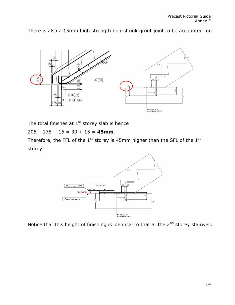
There is also a 15mm high strength non-shrink grout joint to be accounted for.
The total finishes at 1st storey slab is hence
205 – 175 + 15 = 30 + 15 = 45mm.
Therefore, the FFL of the 1st storey is 45mm higher than the SFL of the 1st
storey.
Notice that this height of finishing is identical to that at the 2nd storey stairwell.
Precast Pictorial Guide
Annex E
E-5
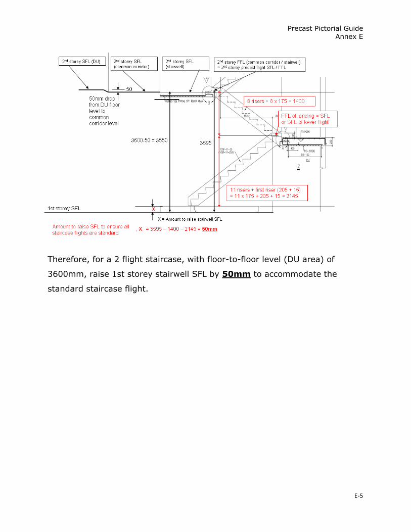
Therefore, for a 2 flight staircase, with floor-to-floor level (DU area) of
3600mm, raise 1st storey stairwell SFL by 50mm to accommodate the
standard staircase flight.

Precast Pictorial Guide
Annex F
F-1
Annex F – HDB’s waterproofing system
F1. Background
Precast components, when jointed on-site, would have horizontal and vertical
joints which are prone to water seepage. Waterproofing details are hence
instrumental, and a good understanding and appreciation by the consultants
is required.
F2. Typical horizontal joint waterproofing system
A typical precast horizontal joint waterproofing system consists of three lines
of defence against water seepage:
a) waterproofing profile on precast component e.g. step profile;
b) waterproofing strip and non-shrink grout between upper and lower
components at kerb; and
c) cementitious waterproofing membrane laid on the floor in the unit.
Note: The horizontal joint gap must be free from any object to allow water to drain
off.

Precast Pictorial Guide
Annex F
F-2
F3. Typical vertical joint waterproofing system
A typical precast vertical joint waterproofing system consists of three
lines of defence against water seepage:
a) Sealant & backing rod;
b) Vertical “V” drip and
c) In-situ concrete

Precast Pictorial Guide
Annex F
F-3
F4. Function of waterproofing membrane sheet
At the intersection between horizontal and vertical joints, waterproofing
membrane sheet plays an important role to prevent the buildup of water head,
discharging the water out through the horizontal joint. The guide drawing
illustrates the use of membrane in many scenarios, and membrane must be
folded properly in order to achieve its desired effect.
Membrane sheets allow
water to discharge at the
horizontal joint,
preventing water flow to
lower floors