Hot Water Solar in Maine - Build-It-SolarHotWaterPanel_sep26-1.pdfMore projects at Hot Water Solar...
14
More projects at www.BuildItSolar.com Hot Water Solar in Maine Steve Smith 2012 This is the 24’x8’ hot water solar panel that I built on our house in western Maine. Our house is earth sheltered—this is on the roof despite the dirt and grass. The panel is framed in pressure treated wood, with plywood and insulation layers. The system is run as drainback; when the pump shuts off, all the water drains into the thermal storage tank in the garage. It is angled for maximum winter performance (I think it is 25 degrees off vertical). Our barn is part of the house, and the panel sits on top of the barn. This puts the bottom of the panel 18 feet above the floor of the garage. There is a 70’ horizontal (sloped), above ground pipe run between the panel and the vertical access to the garage. I insulated both of the 70’ PEX tubes with wrap around foam, then I wrapped the bundle in fiberglass insulation, with duct tape to hold it in place. I then stuffed the package down a black corrugated culvert, all 70’. This was a lot of work—larger culvert would have helped a lot. The original plan was to have the panel done for winter 2011/2012, but life got in the way. I didn’t get the panel turned on until February, and there were still a couple of uninsulated bits of pipe outside. I’ve also worked through several problems in the controller. It now all works well (summer 2012); last year this time we used almost 1 gallon of propane per day for hot water (during the summer); now we’re running about 2 gallons per month, which includes stove and oven. We’ll see what happens next winter.
Transcript of Hot Water Solar in Maine - Build-It-SolarHotWaterPanel_sep26-1.pdfMore projects at Hot Water Solar...

More projects at www.BuildItSolar.com
Hot Water Solar in Maine
Steve Smith 2012
This is the 24’x8’ hot water solar panel that I built on our house in western Maine. Our house is earth sheltered—this is on the roof despite the dirt and grass. The panel is framed in pressure treated wood, with plywood and insulation layers. The system is run as drainback; when the pump shuts off, all the water drains into the thermal storage tank in the garage. It is angled for maximum winter performance (I think it is 25 degrees off vertical). Our barn is part of the house, and the panel sits on top of the barn. This puts the bottom of the panel 18 feet above the floor of the garage. There is a 70’ horizontal (sloped), above ground pipe run between the panel and the vertical access to the garage. I insulated both of the 70’ PEX tubes with wrap around foam, then I wrapped the bundle in fiberglass insulation, with duct tape to hold it in place. I then stuffed the package down a black corrugated culvert, all 70’. This was a lot of work—larger culvert would have helped a lot. The original plan was to have the panel done for winter 2011/2012, but life got in the way. I didn’t get
the panel turned on until February, and there were still a couple of uninsulated bits of pipe outside. I’ve
also worked through several problems in the controller. It now all works well (summer 2012); last year
this time we used almost 1 gallon of propane per day for hot water (during the summer); now we’re
running about 2 gallons per month, which includes stove and oven. We’ll see what happens next winter.
More projects at www.BuildItSolar.com
Structure/construction
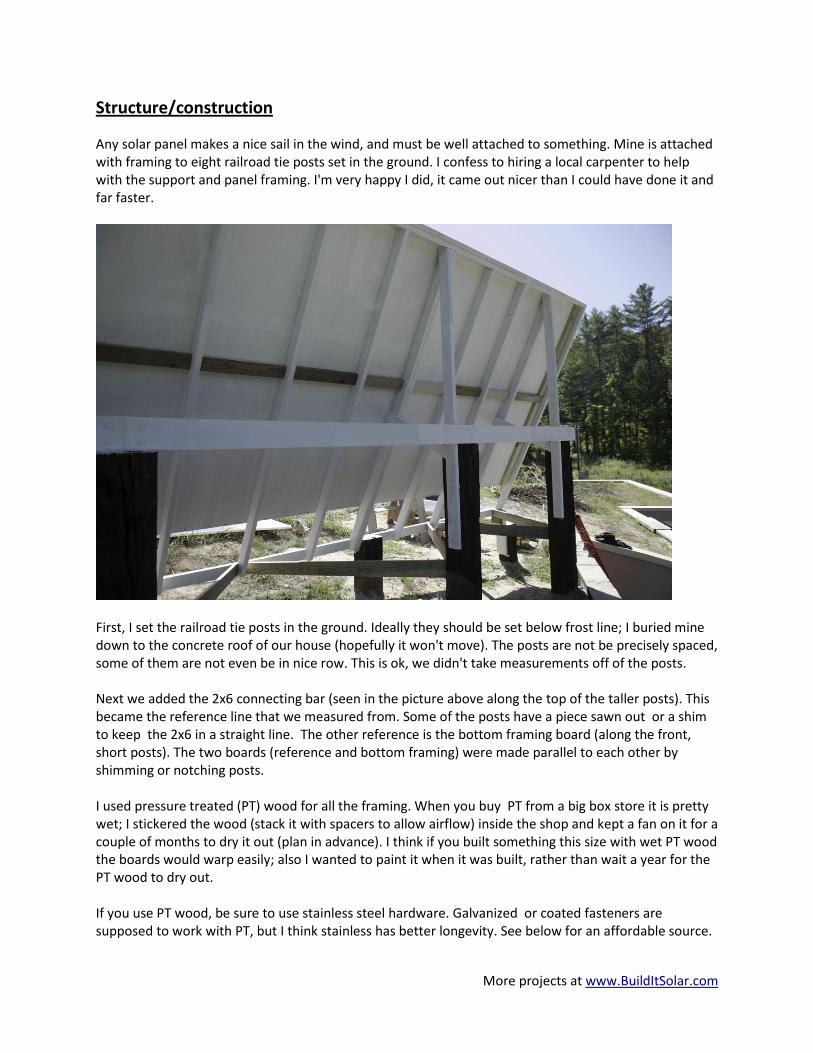
Any solar panel makes a nice sail in the wind, and must be well attached to something. Mine is attached with framing to eight railroad tie posts set in the ground. I confess to hiring a local carpenter to help with the support and panel framing. I'm very happy I did, it came out nicer than I could have done it and far faster.
First, I set the railroad tie posts in the ground. Ideally they should be set below frost line; I buried mine down to the concrete roof of our house (hopefully it won't move). The posts are not be precisely spaced, some of them are not even be in nice row. This is ok, we didn't take measurements off of the posts. Next we added the 2x6 connecting bar (seen in the picture above along the top of the taller posts). This became the reference line that we measured from. Some of the posts have a piece sawn out or a shim to keep the 2x6 in a straight line. The other reference is the bottom framing board (along the front, short posts). The two boards (reference and bottom framing) were made parallel to each other by shimming or notching posts. I used pressure treated (PT) wood for all the framing. When you buy PT from a big box store it is pretty wet; I stickered the wood (stack it with spacers to allow airflow) inside the shop and kept a fan on it for a couple of months to dry it out (plan in advance). I think if you built something this size with wet PT wood the boards would warp easily; also I wanted to paint it when it was built, rather than wait a year for the PT wood to dry out. If you use PT wood, be sure to use stainless steel hardware. Galvanized or coated fasteners are supposed to work with PT, but I think stainless has better longevity. See below for an affordable source.

More projects at www.BuildItSolar.com
This drawing shows the initial framing. It is a lot like building a wall, except you're way up in the air and it is at an angle. It was built in place. Boards are fastened to each other and to the posts by lag screws or carriage bolts. I don't think the framing should be tied into the posts with deck screws, it has to take a lot of wind pressure. Again, all hardware is stainless. About 1/3 from the left side you will see an extra 2x4. This makes up for the position of the corresponding post not being quite right. Otherwise, I used 24” centers for the framing. There is bracing on the back, a long vertical 2x4 bracing the top of the framing and a short diagonal 2x4 bracing the center of the framing. Not shown is the diagonal bracing for the bottom board (see photo on previous page).
More projects at www.BuildItSolar.com
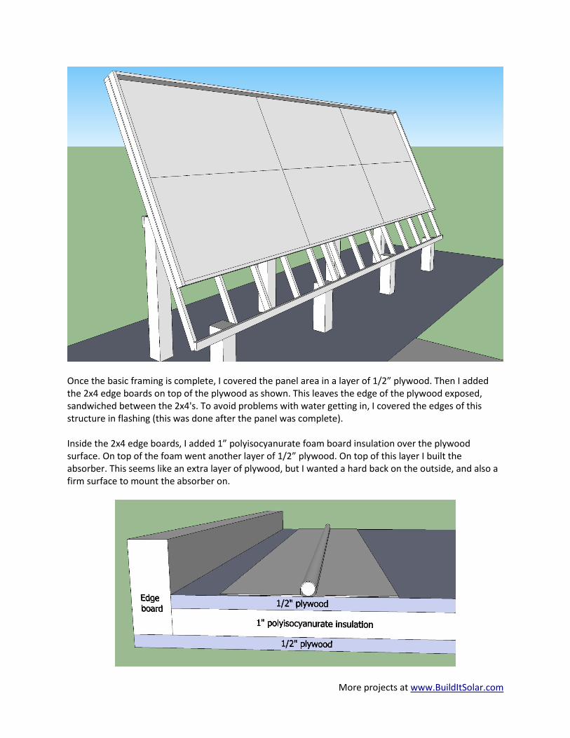
Once the basic framing is complete, I covered the panel area in a layer of 1/2” plywood. Then I added the 2x4 edge boards on top of the plywood as shown. This leaves the edge of the plywood exposed, sandwiched between the 2x4's. To avoid problems with water getting in, I covered the edges of this structure in flashing (this was done after the panel was complete). Inside the 2x4 edge boards, I added 1” polyisocyanurate foam board insulation over the plywood surface. On top of the foam went another layer of 1/2” plywood. On top of this layer I built the absorber. This seems like an extra layer of plywood, but I wanted a hard back on the outside, and also a firm surface to mount the absorber on.

More projects at www.BuildItSolar.com
Glazing
I covered the panel in Tuftex (about the same as Suntuf) corrugated polycarbonate panels. Since there are no panel ribs to attach the Tuftex to along the 24’ width, I added a piece of ½” conduit at every panel junction (you can see these in the first photo). ½” conduit is about the right size to fit under a corrugation. The Tuftex panels were drilled identically by clamping and drilling all the panels at once (with oversize holes as recommended for Tuftex, 1/4”). I thought a spur drill for wood would give the best hole, but an ordinary beveled (sharp!) drill bit works better. I drilled the conduit with the identical spacing. Roofing screws (with epdm washers) are the right thing to use here; they were longer than the conduit diameter, so I drilled through the conduit with the screw minor diameter, then drilled the top side to a larger clearance hole (so that only one edge of the conduit would get caught in the threads). This may work better with the large hole on the bottom of the conduit, I'm not sure. I did not use any caulk between pieces of glazing, just the screws. The corrugated ends are sealed with the foam wiggle strips made for Tuftex; the flat sides are sealed with foam weather stripping.
Absorber Panel
Temperature Sensor Placement The panel sensor should be in a spot where it will get sun, just like the panel, but it should not sense water temperature. I put mine several inches away from the hizer pipe, caulked and covered with a piece of black painted flashing.

More projects at www.BuildItSolar.com
If instead you attach the panel temperature sensor to the hot water return pipe, at first it measures a black, air filled copper pipe. The minute the sun hits it, it gets hot. Pump turns on and fills the panel with cooler water, decreasing the sensor temp. With a little heat loss in getting to the panel, the sensor can end up below tank temperature, which turns off the pump. The system will cycle for a while until all the plumbing is warmed up. Guess how I know….thanks to John in PA on SimplySolar for the fix. With the panel sensor away from the water, it tells you that the sun is out and the flashing is hotter than the tank. As long as this is true, you want to run the pump. The flashing temperature is what this sensor should care about, not the water temperature. Water gets pumped in at the bottom left of the panel, fills the tubing and exits the pipe array from the top right. The water return pipe is routed inside the panel—there is no point in running it outside where you can lose heat. You can see the exit pipe sticking out the bottom at the extreme left in the picture above. Since the return pipe inside the panel is painted black, it doesn’t reduce the panel’s effective area. The absorber has about 400’ of copper pipe in it. It is built in the “hizer” arrangement, where the 1” manifolds run vertically on each end with horizontal runs of ½” pipe connecting them. The absorber is covered in aluminum flashing, grooved to fit the ½” pipe. I made a deal with a local flashing fabricator—he sold me all of his old partial and damaged rolls for a good price. There is a lot of flashing on the panel. The flashing came 24” wide by as long as 50’. I cut it down to 8” strips 24” long. The grooves were formed on a motorized hydraulic press:

More projects at www.BuildItSolar.com
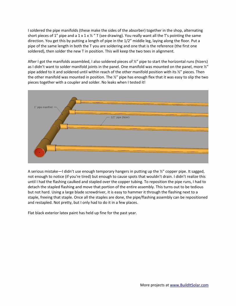
This picture shows a piece of grooved flashing (white, upside down), a piece of right side up grooved flashing (gray) mounted over a copper pipe with the edge clamps in place (note holes in them to allow stapling when clamped), and the air stapler (I don't know how you'd do all this flashing without one). First I put down flat strips of flashing (3 ½” I think, not shown in picture). Next came the copper pipe. Over the top went the grooved flashing, with silicone caulk in the groove and also on the 3 ½” strips, binding it all thermally (at least better than air gaps). The edge clamps were added so the flashing fit nice and tight around the pipe, then the flashing was stapled (stainless staples). The horizontal pipes are slanted about 3” from true horizontal so that water will drain from the panel (but see below). Very affordable stainless staples and other fasteners can be found at Manasquan Premium Fasteners, www.manasquanfasteners.com ). They don't mind small orders from folks like you and I. Any fastener in treated wood should be stainless for longevity. Hot water panels are usually arranged vertically, with small pipes (1/2”) running up and down, joining larger pipes (3/4” to 1”) that run horizontally. The small pipes are called risers, the larger horizontal pipes are called manifolds. My panel is much more horizontal than vertical, so it makes more sense to turn things sideways. In my panel the 1” manifolds run vertically, while the 1/2” pipes run horizontally. In this case, the horizontal pipes are called “hizers” or maybe “hisers” (the idea is from Alan Rushforth, I think). This shortens the manifolds (1” copper isn't cheap) and reduces the number of Tee connections by a factor of 3.
More projects at www.BuildItSolar.com
I soldered the pipe manifolds (these make the sides of the absorber) together in the shop, alternating short pieces of 1” pipe and a 1 x 1 x ½ ” T (see drawing). You really want all the T's pointing the same direction. You get this by putting a length of pipe in the 1/2” middle leg, laying along the floor. Put a pipe of the same length in both the T you are soldering and one that is the reference (the first one soldered), then solder the new T in position. This will keep the two tees in alignment. After I got the manifolds assembled, I also soldered pieces of ½” pipe to start the horizontal runs (hizers) as I didn’t want to solder manifold joints in the panel. One manifold was mounted on the panel, more ½” pipe added to it and soldered until within reach of the other manifold position with its ½” pieces. Then the other manifold was mounted in position. The ½” pipe has enough flex that it was easy to slip the two pieces together with a coupler and solder. No leaks when I tested it!
A serious mistake—I didn’t use enough temporary hangers in putting up the ½” copper pipe. It sagged, not enough to notice (if you're tired) but enough to cause spots that wouldn’t drain. I didn’t realize this until I had the flashing caulked and stapled over the copper tubing. To reposition the pipe runs, I had to detach the stapled flashing and move that portion of the entire assembly. This turns out to be tedious but not hard. Using a large blade screwdriver, it is easy to hammer it through the flashing next to a staple, freeing that staple. Once all the staples are done, the pipe/flashing assembly can be repositioned and restapled. Not pretty, but I only had to do it in a few places. Flat black exterior latex paint has held up fine for the past year.

More projects at www.BuildItSolar.com
Plumbing and other items indoors
I started with a propane fired boiler running a hot water heater and a three zone radiant (in floor) heat setup, all professionally installed. It looks much more baroque after my additions (I don’t have much plumbing experience). This is the new setup:
The pumps in the drawing above are small circulator pumps like you see in this type of heating system. The solar storage tank water is circulated to the panel using a Taco 0011 pump (not shown). The pump sits on the floor and draws water off the bottom of the tank, pretty much as described on BuildItSolar.com. The return line from the panel ends above the tank water level so that the panel can drain when the pump shuts off. I have since added valved connections to allow skipping the hot water heater and entirely shutting off the boiler in the summer. What a nice feeling to see that work. The electric valves are controlled by my home brew controller. If the tank temp is above set point (about 90F), the valve to the boiler closes and the one to the solar tank opens, allowing solar heat to be used to heat the house. The controller also turns on the solar panel Taco pump if the panel is hotter than tank water, and turns the pump off if the tank water is above 150F (see schematic at end). I also modified the Taco zone control box to make sure the boiler wouldn’t come on when there was a heat demand signal if the solar tank was above heating the floor. See below for more detail on the control board.

More projects at www.BuildItSolar.com
Thermal Storage Tank I could only find room for a 200
gallon thermal storage tank. That’s
small for this size panel, but better
than none. The tank takes up
about half of the boiler room; the
hot water heater is right behind
and below it (hidden in picture).
There are two PEX heat
exchangers in the tank, stacked
one on top of the other. The one
on the bottom goes to floor heat,
the one on top is for house hot
water, taking some advantage of
stratification in the tank (hot
water wanting to be hotter).
Since my tank was so small, I
didn’t want to do the exterior
framing with 2x4’s and lose more
volume. Instead I welded a
framework out of 2” x ¼” angle
iron. I do not advise this unless
you are very limited in space, it
was a lot more work than wood
construction.
The tank has ¾” plywood attached
to the inside of the angle iron
frame, with 2” polyisocyanurate insulation inside that. EPDM rubber sheet covers the insulation on the
inside. Pretty standard stuff except for the angle iron.

More projects at www.BuildItSolar.com
Making PEX Coils I’ve seen several examples of PEX heat exchangers where the PEX has been recoiled into a shape that allows water to flow amongst the tubing. What I haven’t seen are instructions showing how to deal with recoiling the PEX. This is what I hope to offer. What you need to recoil PEX is a sturdy, outside frame with an open end. Here is what I made:
There are holes drilled in the wood pieces to allow mounting the pipes in different positions, so you can wind different diameter coils. Mainly the uprights need to be fairly rigid to keep the coils straight. My heat exchangers have two layers. Here is the first layer (inside) going on:
I thought it worked pretty well with two people. One person walks the loose PEX around the frame, the other person stuffs it into place and ties the coils to the vertical CPVC tubing. Several wraps of tubing can be held in place with just lacing, then tie a group off. Use a square knot (not a granny) and polypropylene string (the big box stores carry it, you just have to find it). Note the CPVC tubing on the outside of the coil. When the second coil is added, the CPVC remains as a spacer between the two coils. I would not use regular PVC as it might soften at tank temperatures.

More projects at www.BuildItSolar.com
Here is the second (outer) layer being added:
The first layer is tied to the CPVC tubes, which are left in place to maintain a gap between the two layers. There are some extra tubing pieces are just to help in putting the coils together. Here’s a closeup of the first layer lacing:
Here’s the second layer lacing:
This is a little trickier to thread. In each case, lace a few loops (I think we were doing about six at a time), then tie a knot to hold them in place. This picture is just before tying the knot.
More projects at www.BuildItSolar.com
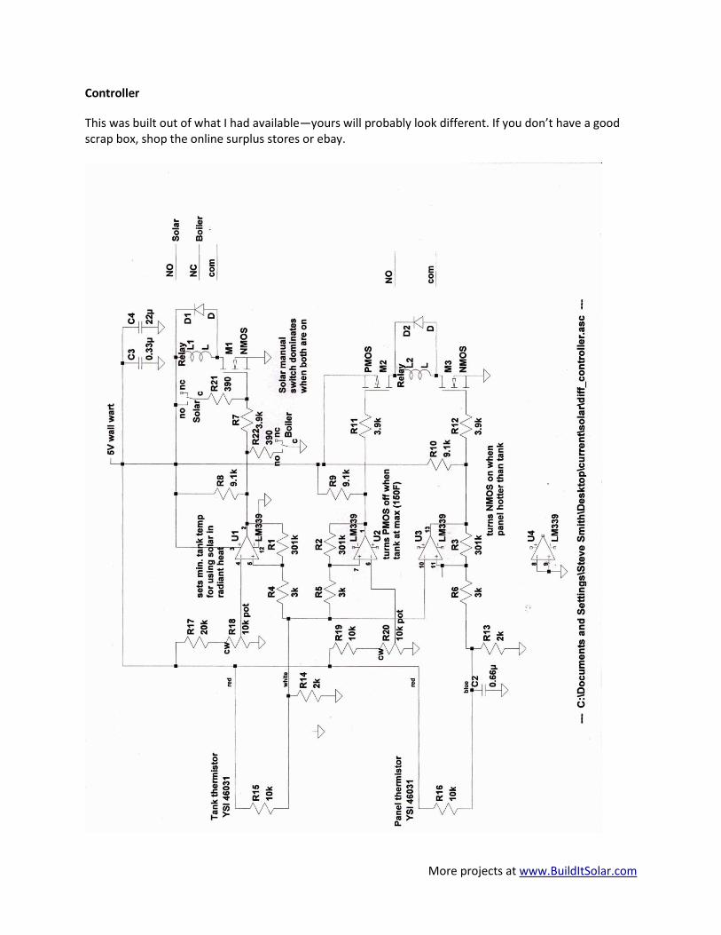
Controller
This was built out of what I had available—yours will probably look different. If you don’t have a good scrap box, shop the online surplus stores or ebay.

More projects at www.BuildItSolar.com
The LM339 is a cheap quad comparator. The top comparator switches when the tank temperature is above 90F (set by the R18 pot). It turns on a fet, M1, which activates a relay. The relay controls the electric valves in the plumbing, so that the radiant floor pipes either draw heat from the solar tank (>90F) or from the boiler. Besides switching the plumbing valves, when >90F the relay output controls a relay in the Taco control box that keeps the boiler from turning on. The middle comparator shuts the solar down when the tank temp is above 150F (set by the R20 pot). When the tank temp is below setpoint, the output of the comparator is low, turning on the pmos fet M2. This allows the possibility of the relay turning on, depending on the third comparator. If the tank temp exceeds setpont, the comparator goes high and turns off the pmos fet. Now there is no way the relay can turn on. The bottom comparator activates the nmos fet M3 if the panel temperature is greater than the tank temperature. The relay will turn on if the tank temperature is less than 150F. The comparators all have 301k resistors from the output to the (+) input. This provides positive feedback, just a little hysteresis to keep the comparator from chattering when close to the switching point. The 301k resistors work against the 3k resistors and other circuitry to provide ~2% hysteresis. There are a couple of manual toggle switches controlling the top relay. These allow setting the relay so that it is locked in "boiler" or "solar" position. Component values are not critical.