Hot Rolling Mill - everloy-spray-nozzles.com · Hot Rolling Mill Other Applications Overlap Having...
20
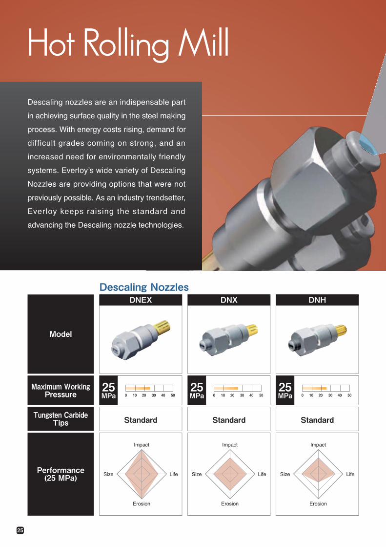
25 Hot Rolling Mill Descaling nozzles are an indispensable part in achieving surface quality in the steel making process. With energy costs rising, demand for difficult grades coming on strong, and an increased need for environmentally friendly u{uvgou0 Gxgtnq{Ôu ykfg xctkgv{ qh Fguecnkpi Pq¦¦ngu ctg rtqxkfkpi qrvkqpu vjcv ygtg pqv previously possible. As an industry trendsetter, Everloy keeps raising the standard and advancing the Descaling nozzle technologies. Descaling Nozzles Model DNEX Standard DNX DNH Standard Standard Maximum Working Pressure Tungsten Carbide Tips 25 MPa 25 MPa 25 MPa 50 40 30 20 10 0 50 40 30 20 10 0 50 40 30 20 10 0 Performance (25 MPa) Impact Life Erosion Size Impact Life Erosion Size Impact Life Erosion Size
Transcript of Hot Rolling Mill - everloy-spray-nozzles.com · Hot Rolling Mill Other Applications Overlap Having...
25
Hot Rolling MillDescaling nozzles are an indispensable part
in achieving surface quality in the steel making
process. With energy costs rising, demand for
difficult grades coming on strong, and an
increased need for environmentally friendly
previously possible. As an industry trendsetter,
Everloy keeps raising the standard and
advancing the Descaling nozzle technologies.
Descaling Nozzles
Model
DNEX
Standard
DNX DNH
Standard Standard
Maximum WorkingPressure
Tungsten CarbideTips
25MPa
25MPa
25MPa5040302010050403020100 50403020100
Performance(25 MPa)
Impact
Life
Erosion
Size
Impact
Life
Erosion
Size
Impact
Life
Erosion
Size
26
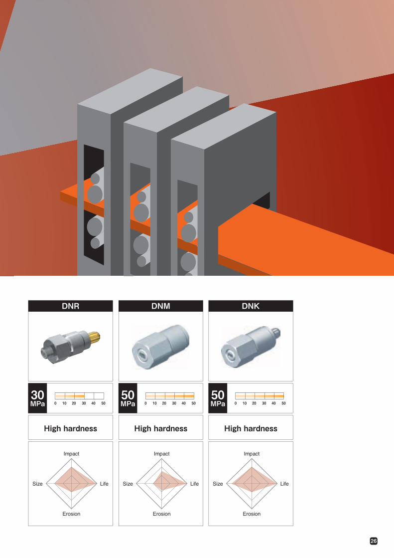
High hardness High hardness High hardness
DNR DNM DNK
30MPa
50MPa
50MPa5040302010050403020100 50403020100
Impact
Life
Erosion
Size
Impact
Life
Erosion
Size
Impact
Life
Erosion
Size
27
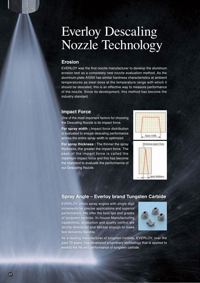
Everloy DescalingNozzle TechnologyErosionEVERLOY was the first nozzle manufacturer to develop the aluminum erosion test as a completely new nozzle evaluation method. As the aluminum plate A1050 has similar hardness characteristics at ambient temperatures as steel does at the temperature range with which it should be descaled, this is an effective way to measure performance of the nozzle. Since its development, this method has become the industry standard.
Impact ForceOne of the most important factors for choosing the Descaling Nozzle is its impact force.
For spray width : Impact force distribution is evaluated to ensure descaling performance across the entire spray width is optimized.
For spray thickness : The thinner the spray thickness, the greater the impact force. The peak of the impact force is cal led the maximum impact force and this has become the standard to evaluate the performance of our Descaling Nozzle.
Spray Angle – Everloy brand Tungsten Carbidep y g y gEVERLOY offers spray angles with single digit increments for precise applications and superior performance. We offer the best tips and grades of tungsten carbide. In-house Manufacturing capabilities, production and quality control are strictly monitored and flexible enough to make fast deliveries feasible.
As a leading manufacturer of tungsten carbide, EVERLOY, over the past 70 years, has developed proprietary technology that is applied to
28
EV
ER
LOY
Tec
hnol
ogy
Con
tinuo
us C
aste
rH
ot
Ro
llin
g M
illO
ther
App
licat
ions
OverlapHaving a proper overlap is extremely important to avoid stripe marking on the strip surface known as “tiger marks”. At the same time, the thickness and waves of the strip need to be considered. Ask an Everloy Sales Representative for the best layout feasible utilizing Everloy s Descaling Calculation Program.
SolutionsHigher impact force options:
1. The latest DNEX technology gives customers a higher impact force than conventional nozzles without increasing water flow/pump capacity.
Improved surface quality by keeping same water flow with the current nozzles.
2. Applying the long nose tip with the wider spray angle model that compensates for the lack of proper spray height and provides appropriate overlap. The long nose tips are normally used for trial purposes only.
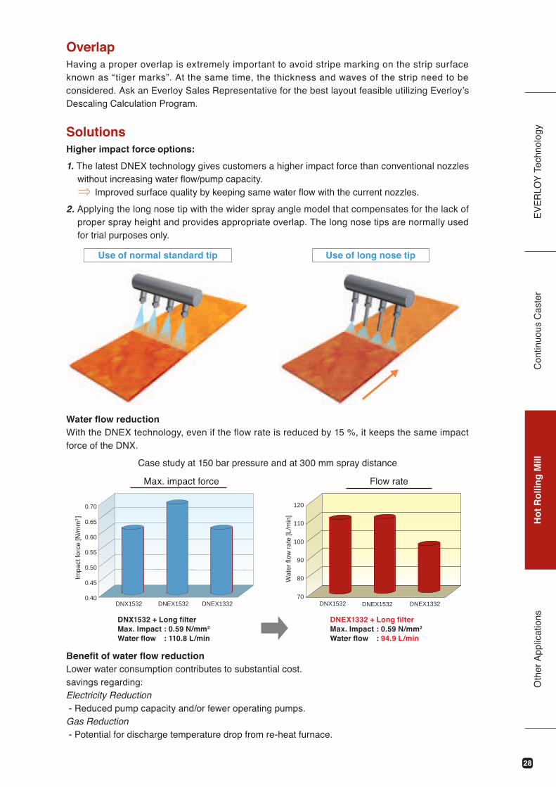
Water flow reductionWith the DNEX technology, even if the flow rate is reduced by 15 %, it keeps the same impact force of the DNX.
Benefit of water flow reduction Lower water consumption contributes to substantial cost. savings regarding: Electricity Reduction - Reduced pump capacity and/or fewer operating pumps.Gas Reduction - Potential for discharge temperature drop from re-heat furnace.
Case study at 150 bar pressure and at 300 mm spray distance
Flow rate
70
80
90
100
110
120
DNX1532 DNEX1532 DNEX1332
Wat
er fl
ow r
ate
[L/m
in]
DNX1532 + Long filterMax. Impact : 0.59 N/mm2
Water flow : 110.8 L/min
DNEX1332 + Long filterMax. Impact : 0.59 N/mm2
Water flow : 94.9 L/min
Use of long nose tipUse of normal standard tip
Max. impact force
DNX1532 DNEX1532 DNEX13320.40
0.45
0.50
0.55
0.60
0.65
0.70
Impa
ct fo
rce
[N/m
m2]
29
EV
ER
LOY
Tec
hnol
ogy
Con
tinuo
us C
aste
rH
ot
Ro
llin
g M
illO
ther
App
licat
ions
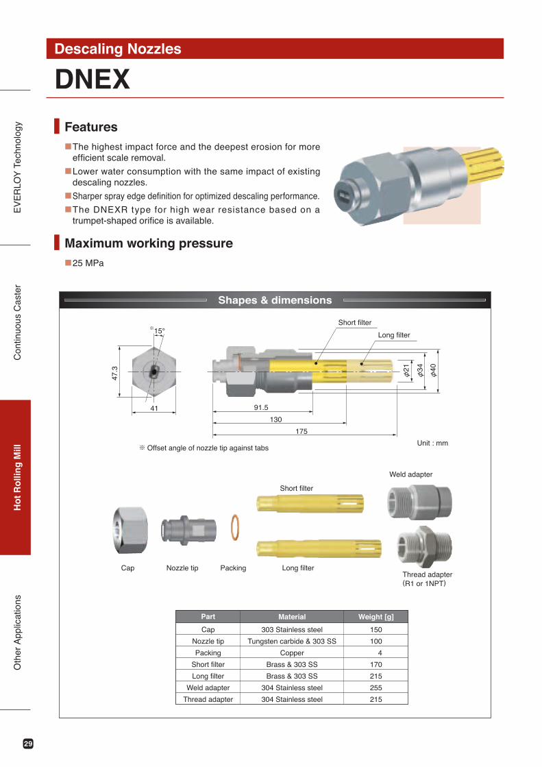
DNEXDescaling Nozzles
Features■
■
■
■
Shapes & dimensions
The highest impact force and the deepest erosion for more efficient scale removal.
Lower water consumption with the same impact of existing descaling nozzles.
Sharper spray edge definition for optimized descaling performance.
The DNEXR type for high wear resistance based on a trumpet-shaped orifice is available.
Maximum working pressure■25 MPa
※
150
100
4
170
215
255
215
41 91.5
130
175
21 34 40
15°
47.3
Material Weight [g]
Offset angle of nozzle tip against tabs※
Cap Nozzle tip Packing
Weld adapter
Thread adapter (R1 or 1NPT)
Part
303 Stainless steel
Tungsten carbide & 303 SS
Copper
Brass & 303 SS
Brass & 303 SS
304 Stainless steel
304 Stainless steel
Cap
Nozzle tip
Packing
Short filter
Long filter
Weld adapter
Thread adapter
Short filter
Long filter
Short filter
Long filter
Unit : mm
30
EV
ER
LOY
Tec
hnol
ogy
Con
tinuo
us C
aste
rH
ot
Ro
llin
g M
illO
ther
App
licat
ions
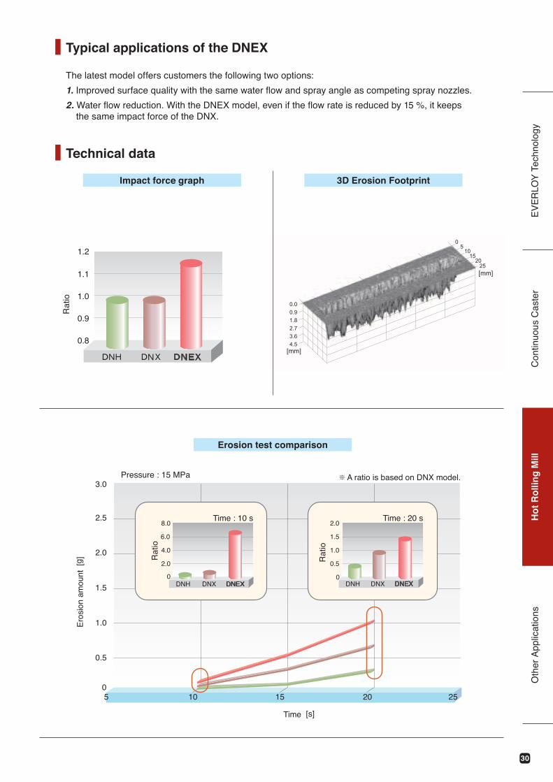
The latest model offers customers the following two options:
1. Improved surface quality with the same water flow and spray angle as competing spray nozzles.
2. Water flow reduction. With the DNEX model, even if the flow rate is reduced by 15 %, it keeps the same impact force of the DNX.
Technical data
Typical applications of the DNEX
Impact force graph
Erosion test comparison
3D Erosion Footprint
[mm]
[mm]
0.8
0.9
1.0
1.1
1.2
3.0
2.5
2.0
1.5
1.0
0.5
05 10 15 20 25
8.0
2.0
0
6.0
4.0
2.0
1.5
1.0
0.5
0DNH DNX DNEX DNH DNX DNEX
[g]
[s]
Ero
sion
am
ount
Time
Rat
io
Pressure : 15 MPa A ratio is based on DNX model.※
Rat
io
Time : 10 s Time : 20 s
Rat
io
31
EV
ER
LOY
Tec
hnol
ogy
Con
tinuo
us C
aste
rH
ot
Ro
llin
g M
illO
ther
App
licat
ions
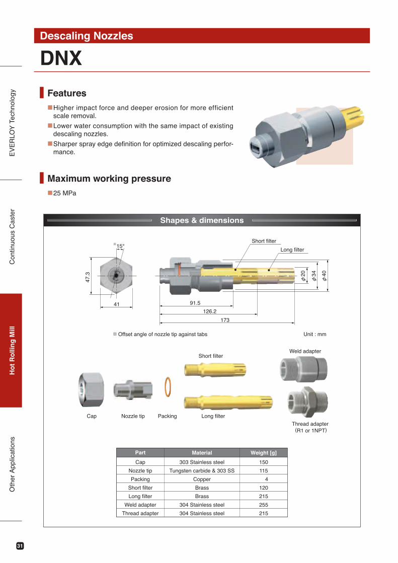
DNXDescaling Nozzles
Features■
■
■
Shapes & dimensions
Higher impact force and deeper erosion for more efficient scale removal.
Lower water consumption with the same impact of existing descaling nozzles.
Sharper spray edge definition for optimized descaling perfor-mance.
Maximum working pressure■25 MPa
150
115
4
120
215
255
215
Material Weight [g]Part
303 Stainless steel
Tungsten carbide & 303 SS
Copper
Brass
Brass
304 Stainless steel
304 Stainless steel
Cap
Nozzle tip
Packing
Short filter
Long filter
Weld adapter
Thread adapter
※
41 91.5
126.2
173
20 34 40
15°
47.3
Short filter
Long filter
Cap Nozzle tip Packing
Weld adapter
Thread adapter (R1 or 1NPT)
Short filter
Long filter
Offset angle of nozzle tip against tabs※ Unit : mm
32
EV
ER
LOY
Tec
hnol
ogy
Con
tinuo
us C
aste
rH
ot
Ro
llin
g M
illO
ther
App
licat
ions
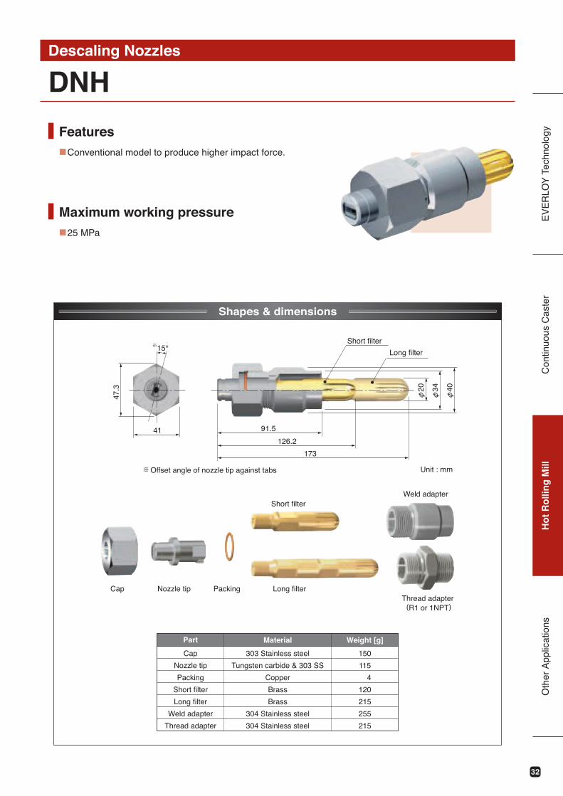
DNHDescaling Nozzles
Features■
Shapes & dimensions
Conventional model to produce higher impact force.
Maximum working pressure■25 MPa
150
115
4
120
215
255
215
Material Weight [g]Part
303 Stainless steel
Tungsten carbide & 303 SS
Copper
Brass
Brass
304 Stainless steel
304 Stainless steel
Cap
Nozzle tip
Packing
Short filter
Long filter
Weld adapter
Thread adapter
※
41 91.5
126.2
173
20 34 40
15°
47.3
Offset angle of nozzle tip against tabs※
Short filter
Long filter
Cap Nozzle tip Packing
Weld adapter
Thread adapter (R1 or 1NPT)
Short filter
Long filter
Unit : mm
33
EV
ER
LOY
Tec
hnol
ogy
Con
tinuo
us C
aste
rH
ot
Ro
llin
g M
illO
ther
App
licat
ions
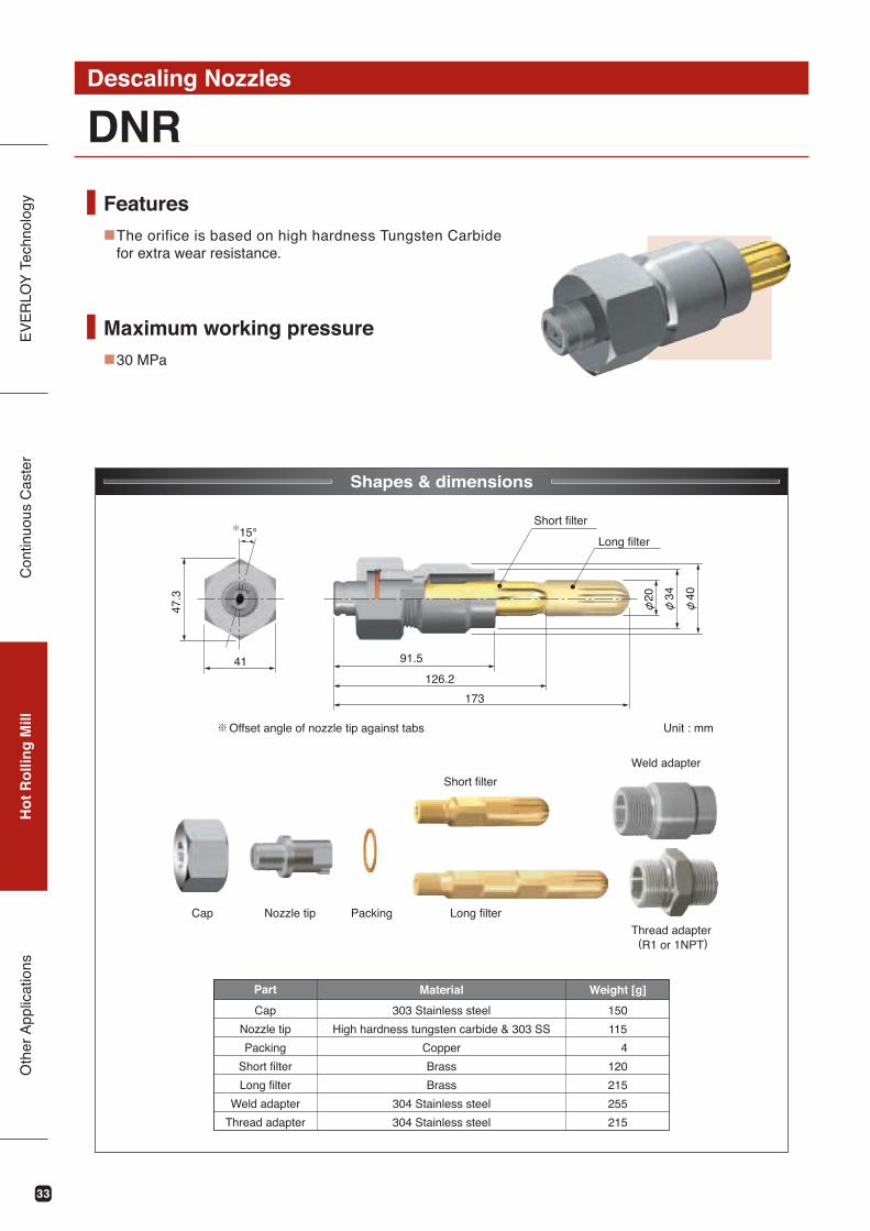
DNRDescaling Nozzles
Shapes & dimensions
Features■The orifice is based on high hardness Tungsten Carbide
for extra wear resistance.
Maximum working pressure■30 MPa
150
115
4
120
215
255
215
Material Weight [g]Part
303 Stainless steel
High hardness tungsten carbide & 303 SS
Copper
Brass
Brass
304 Stainless steel
304 Stainless steel
Cap
Nozzle tip
Packing
Short filter
Long filter
Weld adapter
Thread adapter
※
41 91.5
126.2
173
34 40
15°
47.3 20
Offset angle of nozzle tip against tabs※
Short filter
Long filter
Cap Nozzle tip Packing
Weld adapter
Thread adapter (R1 or 1NPT)
Short filter
Long filter
Unit : mm
34
EV
ER
LOY
Tec
hnol
ogy
Con
tinuo
us C
aste
rH
ot
Ro
llin
g M
illO
ther
App
licat
ions
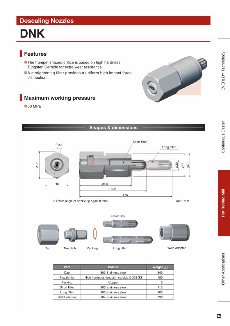
DNKDescaling Nozzles
Features■
■
Shapes & dimensions
The trumpet shaped orifice is based on high hardness Tungsten Carbide for extra wear resistance.
A straightening filter provides a uniform high impact force distribution.
Maximum working pressure■50 MPa
345
180
5
113
203
530
Material Weight [g]Part
303 Stainless steel
High hardness tungsten carbide & 303 SS
Copper
303 Stainless steel
303 Stainless steel
304 Stainless steel
Cap
Nozzle tip
Packing
Short filter
Long filter
Weld adapter
46 98.5
129.2
176
20 44 46
※15°
52
Offset angle of nozzle tip against tabs※
Short filter
Long filter
Cap Nozzle tip Packing Weld adapter
Short filter
Long filter
Unit : mm
35
EV
ER
LOY
Tec
hnol
ogy
Con
tinuo
us C
aste
rH
ot
Ro
llin
g M
illO
ther
App
licat
ions
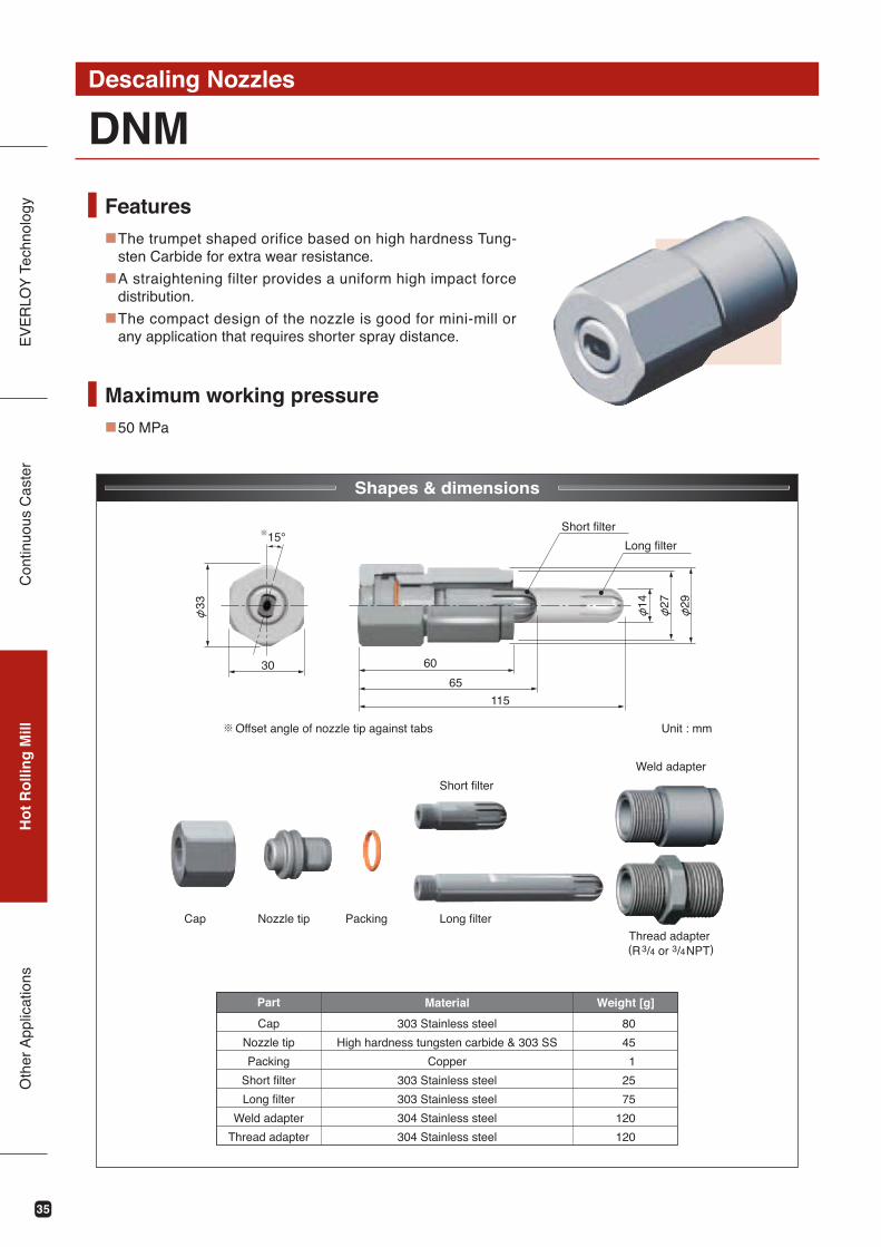
DNMDescaling Nozzles
Shapes & dimensions
Features■
■
■
The trumpet shaped orifice based on high hardness Tung-sten Carbide for extra wear resistance.
A straightening filter provides a uniform high impact force distribution.
The compact design of the nozzle is good for mini-mill or any application that requires shorter spray distance.
Maximum working pressure■50 MPa
80
45
1
25
75
120
120
Material Weight [g]Part
303 Stainless steel
High hardness tungsten carbide & 303 SS
Copper
303 Stainless steel
303 Stainless steel
304 Stainless steel
304 Stainless steel
Cap
Nozzle tip
Packing
Short filter
Long filter
Weld adapter
Thread adapter
※
30 60
65
115
14 27 29
15°
33
Cap Nozzle tip Packing
Weld adapter
Thread adapter (R3/4 or 3/4NPT)
Short filter
Long filter
Offset angle of nozzle tip against tabs※
Short filter
Long filter
Unit : mm
36
EV
ER
LOY
Tec
hnol
ogy
Con
tinuo
us C
aste
rH
ot
Ro
llin
g M
illO
ther
App
licat
ions
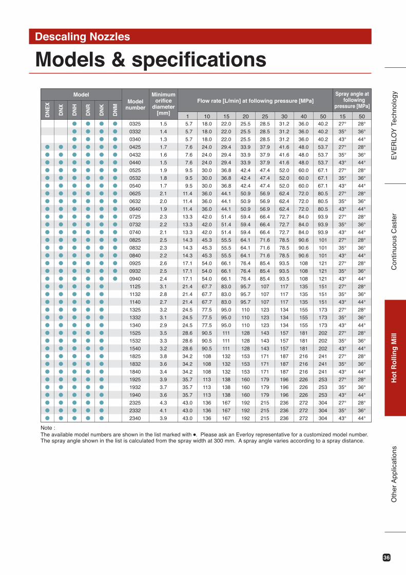
Models & specificationsDescaling Nozzles
ModelModel
number
Minimumorifice
diameter[mm]
Flow rate [L/min] at following pressure [MPa]Spray angle at
followingpressure [MPa]
50 5040.2
40.2
40.2
53.7
53.7
53.7
67.1
67.1
67.1
80.5
80.5
80.5
93.9
93.9
93.9
101
101
101
121
121
121
151
151
151
173
173
173
202
202
202
241
241
241
253
253
253
304
304
304
4036.0
36.0
36.0
48.0
48.0
48.0
60.0
60.0
60.0
72.0
72.0
72.0
84.0
84.0
84.0
90.6
90.6
90.6
108
108
108
135
135
135
155
155
155
181
181
181
216
216
216
226
226
226
272
272
272
3031.2
31.2
31.2
41.6
41.6
41.6
52.0
52.0
52.0
62.4
62.4
62.4
72.7
72.7
72.7
78.5
78.5
78.5
93.5
93.5
93.5
117
117
117
134
134
134
157
157
157
187
187
187
196
196
196
236
236
236
2528.5
28.5
28.5
37.9
37.9
37.9
47.4
47.4
47.4
56.9
56.9
56.9
66.4
66.4
66.4
71.6
71.6
71.6
85.4
85.4
85.4
107
107
107
123
123
123
143
143
143
171
171
171
179
179
179
215
215
215
2025.5
25.5
25.5
33.9
33.9
33.9
42.4
42.4
42.4
50.9
50.9
50.9
59.4
59.4
59.4
64.1
64.1
64.1
76.4
76.4
76.4
95.7
95.7
95.7
110
110
110
128
128
128
153
153
153
160
160
160
192
192
192
1522.0
22.0
22.0
29.4
29.4
29.4
36.8
36.8
36.8
44.1
44.1
44.1
51.4
51.4
51.4
55.5
55.5
55.5
66.1
66.1
66.1
83.0
83.0
83.0
95.0
95.0
95.0
111
111
111
132
132
132
138
138
138
167
167
167
1018.0
18.0
18.0
24.0
24.0
24.0
30.0
30.0
30.0
36.0
36.0
36.0
42.0
42.0
42.0
45.3
45.3
45.3
54.0
54.0
54.0
67.7
67.7
67.7
77.5
77.5
77.5
90.5
90.5
90.5
108
108
108
113
113
113
136
136
136
1 5.7
5.7
5.7
7.6
7.6
7.6
9.5
9.5
9.5
11.4
11.4
11.4
13.3
13.3
13.3
14.3
14.3
14.3
17.1
17.1
17.1
21.4
21.4
21.4
24.5
24.5
24.5
28.6
28.6
28.6
34.2
34.2
34.2
35.7
35.7
35.7
43.0
43.0
43.0
28°
36°
44°
28°
36°
44°
28°
36°
44°
28°
36°
44°
28°
36°
44°
28°
36°
44°
28°
36°
44°
28°
36°
44°
28°
36°
44°
28°
36°
44°
28°
36°
44°
28°
36°
44°
28°
36°
44°
1527°
35°
43°
27°
35°
43°
27°
35°
43°
27°
35°
43°
27°
35°
43°
27°
35°
43°
27°
35°
43°
27°
35°
43°
27°
35°
43°
27°
35°
43°
27°
35°
43°
27°
35°
43°
27°
35°
43°
1.5
1.4
1.3
1.7
1.6
1.5
1.9
1.8
1.7
2.1
2.0
1.9
2.3
2.2
2.1
2.5
2.3
2.2
2.6
2.5
2.4
3.1
2.8
2.7
3.2
3.1
2.9
3.5
3.3
3.2
3.8
3.6
3.4
3.9
3.7
3.6
4.3
4.1
3.9
0325
0332
0340
0425
0432
0440
0525
0532
0540
0625
0632
0640
0725
0732
0740
0825
0832
0840
0925
0932
0940
1125
1132
1140
1325
1332
1340
1525
1532
1540
1825
1832
1840
1925
1932
1940
2325
2332
2340
DN
EX
DN
X
DN
H
DN
R
DN
K
DN
M
Note : The available model numbers are shown in the list marked with ●. Please ask an Everloy representative for a customized model number. The spray angle shown in the list is calculated from the spray width at 300 mm. A spray angle varies according to a spray distance.
37
EV
ER
LOY
Tec
hnol
ogy
Con
tinuo
us C
aste
rH
ot
Ro
llin
g M
illO
ther
App
licat
ions
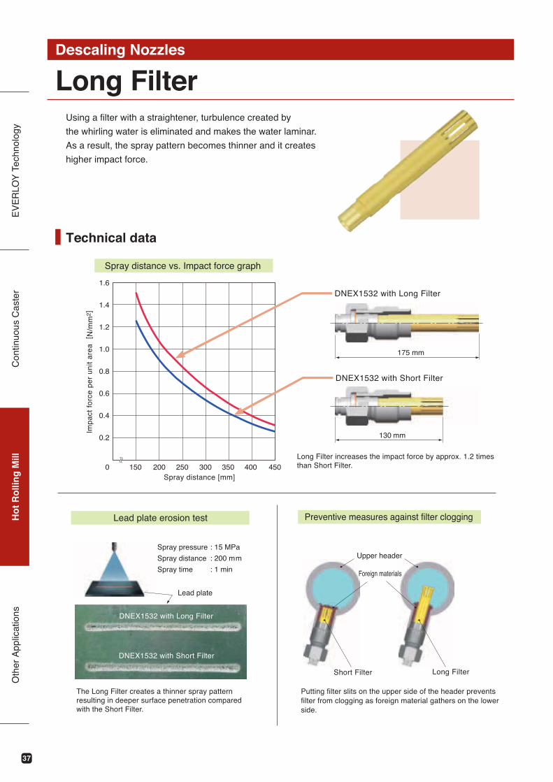
Using a filter with a straightener, turbulence created by
the whirling water is eliminated and makes the water laminar.
As a result, the spray pattern becomes thinner and it creates
higher impact force.
Long FilterDescaling Nozzles
Technical data
Preventive measures against filter clogging
Upper header
Foreign materials
Short Filter Long Filter
Lead plate erosion test
Spray pressure
Spray distance
Spray time
Putting filter slits on the upper side of the header prevents filter from clogging as foreign material gathers on the lower side.
130 mm
175 mm
Spray distance vs. Impact force graph
DNEX1532 with Long Filter
DNEX1532 with Short Filter
Long Filter increases the impact force by approx. 1.2 timesthan Short Filter.
Spray distance [mm]
Imp
act
fo
rce
pe
r u
nit
are
a [
N/m
m2]
150 200 250 300 350 400 4500
1.6
1.4
1.2
1.0
0.8
0.6
0.4
0.2
~ ~
: 15 MPa
: 200 mm
: 1 min
The Long Filter creates a thinner spray patternresulting in deeper surface penetration comparedwith the Short Filter.
Lead plate
DNEX1532 with Long Filter
DNEX1532 with Short Filter
38
EV
ER
LOY
Tec
hnol
ogy
Con
tinuo
us C
aste
rH
ot
Ro
llin
g M
illO
ther
App
licat
ions
Descaling Check Valve (DCV)Descaling Nozzles
Shapes & dimensions
Features■
■
Optimized internal structure offers less pressure loss which results in higher impact force.
Good for preventing:
- water hammer, bypass water, temperature drop of
steel plates.
Maximum working pressure■30 MPa
22L
Cylinder Spring Piston Filter
Unit : mm
Part Material
Cylinder
Spring
Piston
Filter
303 Stainless steel
304 Stainless steel
304 Stainless steel
304 Stainless steel
250
330
290
DNH・DNR
DNX
DNEX
01V00
01V01
143
189.5
191.5
1.0
0.6
0.601V04
Model Part No.Dimension Operating
pressure [MPa]Weight
L [mm] [g]
39
EV
ER
LOY
Tec
hnol
ogy
Con
tinuo
us C
aste
rH
ot
Ro
llin
g M
ill
RemoverDescaling Nozzles
Screw remover
Three types of remover tools are available.
You can remove the nozzle unit more easily with them.
Handle
Nozzle guide
Instructions
Groove
Adapter
Detach the cap and put the end of the tool in the groove in the nozzle tip.
Push the nozzle guide toward the adapter.
Adapter
Turn the tool handle counterclockwise. The nozzle can be removed.
With the cap detached, put the screwremover in the nozzle tip groove andpull out the nozzle by turning the toolhandle.The nozzle is held in the nozzle guideof the remover so as to prevent it fromdropping during removal.
Part No.Model
01J00
01J01
01J02
01J10
DNH.DNR.DNX
DNM
DNK
DNEX
1 2
3 4
Oth
er A
pplic
atio
ns
40
EV
ER
LOY
Tec
hnol
ogy
Con
tinuo
us C
aste
rH
ot
Ro
llin
g M
ill
C-type remover
Pull-out remover
Instructions
Instructions
1 2 3
1 2 3
Handle
Groove
Groove
The nozzle can be removed.
Put the C-type remover in the groove in the nozzle tip.
Turn the cap counterclockwise by using a wrench or spanner.
The nozzle can be removed together with the cap.
Detach the cap and put the end of the tool in the groove in the nozzle tip.
Pull the handle.
Prior to loosening the cap, put the C-type removerin the groove in the tip end.You can pull out and remove the nozzle easily byloosening the cap.
With the cap detached, put the pull-out removerin the groove in the nozzle tip and pull the handle.You can pull out the nozzle with ease.
Part No.Model
01J04
01J05
01J06
DNH.DNR.DNX.DNEX
DNM
DNK
Part No.Model
01J03
01J12
DNH.DNR.DNX
DNEX
Oth
er A
pplic
atio
ns
41
EV
ER
LOY
Tec
hnol
ogy
Con
tinuo
us C
aste
rH
ot
Ro
llin
g M
illO
ther
App
licat
ions
Protective CapDescaling Nozzles
Standard type
Flange type
Full face type
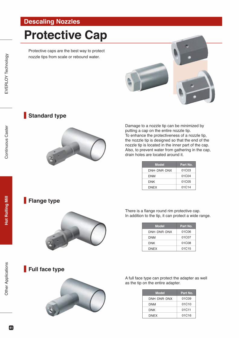
Protective caps are the best way to protect
nozzle tips from scale or rebound water.
Damage to a nozzle tip can be minimized by putting a cap on the entire nozzle tip. To enhance the protectiveness of a nozzle tip, the nozzle tip is designed so that the end of the nozzle tip is located in the inner part of the cap. Also, to prevent water from gathering in the cap, drain holes are located around it.
There is a flange round rim protective cap.In addition to the tip, it can protect a wide range.
A full face type can protect the adapter as well as the tip on the entire adapter.
Part No.Model
01C03
01C04
01C05
01C14
DNH.DNR.DNX
DNM
DNK
DNEX
Part No.Model
01C06
01C07
01C08
01C15
DNH.DNR.DNX
DNM
DNK
DNEX
Part No.Model
01C09
01C10
01C11
01C16
DNH.DNR.DNX
DNM
DNK
DNEX
42
EV
ER
LOY
Tec
hnol
ogy
Con
tinuo
us C
aste
rH
ot
Ro
llin
g M
illO
ther
App
licat
ions
Alignment Tip and BarDescaling Nozzles
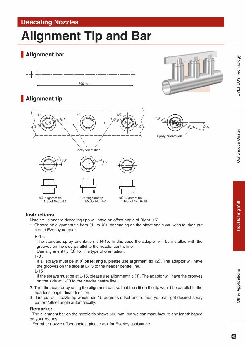
Alignment tip
Alignment bar
500 mm
(1) (2) (3)
Spray orientation
Spray orientation
(3) Alignmet tip Model No. R-15
(2) Alignmet tip Model No. F-0
(2) Alignmet tip Model No. L-15
Instructions:
1. Choose an alignment tip from (1) to (3), depending on the offset angle you wish to, then put it onto Everloy adapter.
R-15:The standard spray orientation is R-15. In this case the adaptor will be installed with the grooves on the side parallel to the header centre line.Use alignment tip (3) for this type of orientation.
F-0 :(2). The adaptor will have
the grooves on the side at L-15 to the header centre line.L-15 :If the sprays must be at L-15, please use alignment tip (1). The adaptor will have the grooves on the side at L-30 to the header centre line.
2. Turn the adapter by using the alignment bar, so that the slit on the tip would be parallel to the header's longitudinal direction.
3. Just put our nozzle tip which has 15 degrees offset angle, then you can get desired spray pattern/offset angle automatically.
Remarks:- The alignment bar on the nozzle tip shows 500 mm, but we can manufacture any length based on your request.- For other nozzle offset angles, please ask for Everloy assistance.
43
EV
ER
LOY
Tec
hnol
ogy
Con
tinuo
us C
aste
rH
ot
Ro
llin
g M
illO
ther
App
licat
ions
Handling manualDescaling Nozzles
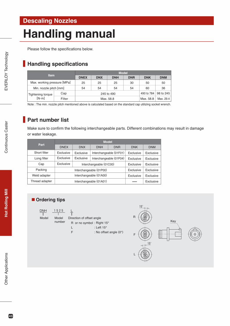
Part number list
Handling specifications
Make sure to confirm the following interchangeable parts. Different combinations may result in damage
or water leakage.
R
L
F
DNX DNRDNH DNMDNK
25
DNEX
25
Max. 58.8
245 to 490
25 30 5050
Max. 58.8
490 to 784
Max. 29.4
98 to 245
DNEX DNX DNH DNR DNK DNM
54 60 3654 54 54
[N.m]
Please follow the specifications below.
ItemModel
Max. working pressure [MPa]
Min. nozzle pitch [mm]
Tightening torque Cap
Filter
Note : The min. nozzle pitch mentioned above is calculated based on the standard cap utilizing socket wrench.
Part
Exclusive
Interchangeable (01P00)
Model
Short filter
Long filter
Cap
Packing
Weld adapter
Thread adapter
Exclusive
Exclusive
Exclusive
Exclusive
Exclusive
Exclusive
Exclusive
Exclusive
Exclusive
Exclusive
Exclusive
Exclusive
Exclusive
Exclusive
Exclusive
Interchangeable (01A00)
Interchangeable (01A01)
Interchangeable (01C00)
Interchangeable (01F01)
Interchangeable (01F04)
Ordering tips
Model Modelnumber : Right 15°
: Left 15°
: No offset angle (0°)
Direction of offset angle
R or no symbol
L
F
Key
44
EV
ER
LOY
Tec
hnol
ogy
Con
tinuo
us C
aste
rH
ot
Ro
llin
g M
illO
ther
App
licat
ions
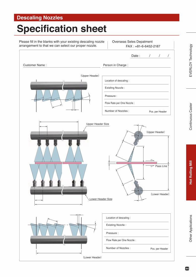
Specification sheetDescaling Nozzles
Overseas Seles DepatmentFAX : +81-6-6452-2187
Date : / / /
Location of descaling :
Existing Nozzle :
Pressure :
Flow Rate per One Nozzle :
Number of Nozzles : Pcs. per Header
Please fill in the blanks with your existing descaling nozzlearrangemwnt to that we can select our proper nozzle.
Customer Name : Person in Charge :
(Upper Header)
Upper Header Size
Lower Header Size
(Lower Header)
(Upper Header)
(Lower Header)
Pass Line
Location of descaling :
Existing Nozzle :
Pressure :
Flow Rate per One Nozzle :
Number of Nozzles : Pcs. per Header