Hot-Pressing Device PF-101 - tdm.habasit.com · The hot-pressing device PF-101 is a double side...
33
Habasit AG Postfach, CH-4153 Reinach-Basel Phone ++41 61 715 15 15 Fax ++41 61 715 15 55 Operating Instructions 36010 Author: Nyk/Ni/AA Page 1 of 33 Edition: 04/0606 Subject to alterations Replaces: 03/0405 Hot-Pressing Device PF-101 The PF-101 is a hot-pressing device for joining of Habasit belts and tapes up to a width of 100 mm / 4 in. and a thickness of 6 mm / 0.24 in. Maximum finger length is 120 mm / 4.8 in. It is designed mainly for Flexproof‚ but Thermofix is also possible. It features a precise individual temperature control of both press plates‚ and the automatically controlled forced air cooling system ensures hassle free operation‚ especially on installations. The compact control unit is connected to the press body by cables of about 2 m length‚ ideal for install situations. Handles can be fitted to the press body in various places for optimum handling in different installation situations. The press body halves can be separated for easy installation in tight space conditions‚ or the press can be inserted over the belt in one piece like a tong‚ and then closed at the front. Pressure is applied by tightening two screws.
-
Upload
vuongtuong -
Category
Documents
-
view
213 -
download
0
Transcript of Hot-Pressing Device PF-101 - tdm.habasit.com · The hot-pressing device PF-101 is a double side...

Habasit AG Postfach, CH-4153 Reinach-Basel Phone ++41 61 715 15 15 Fax ++41 61 715 15 55
Operating Instructions 36010
Author: Nyk/Ni/AA Page 1 of 33 Edition: 04/0606 Subject to alterations Replaces: 03/0405
Hot-Pressing Device PF-101
The PF-101 is a hot-pressing device for joining of Habasit belts and tapes up to a width of 100 mm / 4 in. and a thickness of 6 mm / 0.24 in. Maximum finger length is 120 mm / 4.8 in. It is designed mainly for Flexproof‚ but Thermofix is also possible. It features a precise individual temperature control of both press plates‚ and the automatically controlled forced air cooling system ensures hassle free operation‚ especially on installations.
The compact control unit is connected to the press body by cables of about 2 m length‚ ideal for install situations. Handles can be fitted to the press body in various places for optimum handling in different installation situations. The press body halves can be separated for easy installation in tight space conditions‚ or the press can be inserted over the belt in one piece like a tong‚ and then closed at the front. Pressure is applied by tightening two screws.

Operating instructions 36010
Hot pressing device PF-101
Page 2 of 33 Edition: 04/0606 Subject to alterations
Table of contents
1. General information............................................................................................................................ 4 1.1 Application............................................................................................................................................. 4 1.2 Important safety terms .......................................................................................................................... 4 1.3 Scope of supply..................................................................................................................................... 5 1.3.1 Available accessories ........................................................................................................................... 5 1.4 Ordering of accessories/spare parts..................................................................................................... 6 1.5 Warranty................................................................................................................................................ 6 1.6 Technical advice ................................................................................................................................... 6 2. Mode of operation............................................................................................................................... 7 3. Initial start-up ...................................................................................................................................... 7 4. Hot-pressing of the belt/tape ............................................................................................................. 8 4.1 Procedure:............................................................................................................................................. 8 4.2 Special hints........................................................................................................................................ 10 4.2.1 Removing the top press part completely ............................................................................................ 10 4.2.2 Handling the press like a tong............................................................................................................. 10 5. Control unit........................................................................................................................................ 11 5.1 Front panel .......................................................................................................................................... 11 5.1.1 Illustration............................................................................................................................................ 11 5.1.2 Table of elements and their function................................................................................................... 12 5.2 Operation of the control unit................................................................................................................ 13 5.2.1 Entering joining parameters ................................................................................................................ 13 5.2.2 Running the joining cycle .................................................................................................................... 13 5.2.3 Interrupting the joining cycle ............................................................................................................... 14 5.3 Parametrisation of the control unit ...................................................................................................... 15 5.3.1 List of user accessible parameters ..................................................................................................... 16 6. Service................................................................................................................................................ 17 6.1 Maintenance........................................................................................................................................ 17 6.2 Measuring of the plate temperature.................................................................................................... 17 6.3 Adjustment of the temperature............................................................................................................ 18 6.4 Replacement of the power cord.......................................................................................................... 18 6.5 Replacement of the transformer safety fuse....................................................................................... 19 7. Illustrations........................................................................................................................................ 20 7.1 Overview ............................................................................................................................................. 20 7.2 Press ................................................................................................................................................... 21 7.3 Press open .......................................................................................................................................... 22 8. Technical data ................................................................................................................................... 23 8.1 Data..................................................................................................................................................... 23 8.2 Identification labels.............................................................................................................................. 23 9. List of Habasit belt types that can be Thermofix joined with PF-101.......................................... 24 10 Drawings............................................................................................................................................ 25 10.1 Connection diagram............................................................................................................................ 25 10.2 Assembly of press............................................................................................................................... 26 10.3 Set-up plate......................................................................................................................................... 28 10.4 Control unit.......................................................................................................................................... 29 10.5 Preparation scheme for Flexproof fingers with 120mm...................................................................... 30

Operating instructions 36010
Hot pressing device PF-101
Page 3 of 33 Edition: 04/0606 Subject to alterations
Appendix:
Checklist preventive maintenance
Report sheet preventive maintenance
Product Liability

Operating instructions 36010
Hot pressing device PF-101
Page 4 of 33 Edition: 04/0606 Subject to alterations
1. General information
1.1 Application
The hot-pressing device PF-101 has been designed for manual, portable Flexproof, Quickmelt and, to a limited extent, Thermofix hot-pressing of Habasit belt and tape range up to 100 mm /4.0 in. wide and 6 mm / 0.24 in. thick. Flexproof is possible up to a finger length of 80 mm, or 120 mm by using the additional heat equalizing plates provided.
The PF-101 hot-pressing device was developed solely for the purposes described in the operating instructions. Improper use, or use for other reasons than those described in the instructions, is not permissible. Habasit accepts no liability for the consequences of improper application.
The hot-pressing device PF-101 is manufactured according to recognized engineering principles and state-of-the-art technology, and complies with applicable regulations.
These operating instructions imply that all assembly, maintenance, and repair work, as well as operation of the press, be carried out by skilled personnel or monitored by responsible specialists.
For reasons of scope, these instructions cannot cover all possible aspects of operation, maintenance, or repair. The indications given herein refer to the use of the machines according to their designated purpose by skilled personnel.
In case of doubt or if further detailed information is required, please consult the manufacturer (Chapter 1.4)
1.2 Important safety terms
In these operating instructions, you will find the terms WARNING, CAUTION, and INDICATION. They signal dangers or special information to be borne in mind.
WARNING If disregarded, there is a danger of severe injury, and/or severe material damage.
CAUTION If disregarded, there is a danger of injury, and/or material damage may be caused.
INDICATION Technical information is emphasized if it is important and not readily apparent, even for skilled personnel.
Please observe all indications for assembling, operating, and maintaining the machines, as well as all technical data! This will prevent possible trouble and/or damage to people or materials.
Skilled personnel refer to persons authorized to perform the required work. These people have been sufficiently trained and introduced to their field of activity so that they are able to recognize and prevent dangers. They are aware of the pertinent provisions and safety regulations.

Operating instructions 36010
Hot pressing device PF-101
Page 5 of 33 Edition: 04/0606 Subject to alterations
1.3 Scope of supply
Qty. Item Order No.
1 Hot-pressing device PF-101 230V~, EURO 690410 or
1 Hot-pressing device PF-101 120V~, USA 690400
1 Allen wrench 701029
1 Operating instructions 36010
Packed in cardboard box
1.3.1 Available accessories
• Shim (metallic side strip) set 709568 [Strips to control lateral flow of belt material when fusing(Flexproof or Quickmelt) joints]
• Scissors for cutting of Flexproof fingers AF-102 A-0336910 (8/30 fingers up to 100 mm / 4 in. wide)
• Punching device for Flexproof fingers AF-30 A-0300910 (6/30 or 8/30 fingers up to 30 mm / 1.2 in. wide)
• Punching device for Flexproof fingers AF-61 690715 (6/30 fingers up to 60 mm / 2.4 in. wide)
• Punching device for Flexproof fingers AF-61 690710 (8/30 fingers up to 60 mm / 2.4 in. wide)
• Punching device for Flexproof fingers AF-100/US (10/80, 10/120 fingers up to 100 mm / 4 in. wide)
• Temperature measuring device (N-28714 or N-28715) for checking the pressing temperature

Operating instructions 36010
Hot pressing device PF-101
Page 6 of 33 Edition: 04/0606 Subject to alterations
1.4 Ordering of accessories/spare parts
Spare parts and accessories can be ordered directly from the manufacturer.
Address: Habasit Italiana S.p.A. Via A. Meucci 8, Zona Industriale I-31029 Vittorio Veneto/TV Tel. ++39 438 91 13 Fax ++39 438 91 2374
Exception: AF-100/US, this can be ordered from: Habasit Belting, Inc. 305 Satellite Boulevard USA – Suwanee, GA 30024 Tel. ++001 678 288 36 00 Fax ++001 678 288 36 51
Please accurately describe the parts required. State the numbers according to Section 10. Drawings and, if applicable, the required electric voltage for connection to the mains.
WARNING The use of parts by other manufacturers not meeting Habasit specifications is not admissible. Habasit declines all responsibility for the consequences if non-Habasit parts are used.
1.5 Warranty
All tools undergo a strict final inspection. On the assumption of correct handling, they are warranted against material and manufacturing defects for 1 year.
1.6 Technical advice
Our specialists will be pleased to advise you. For technical questions concerning function and condition of the hot-pressing device, please contact the manufacturer (see Chapter 1.4 for the address).

Operating instructions 36010
Hot pressing device PF-101
Page 7 of 33 Edition: 04/0606 Subject to alterations
2. Mode of operation
Numbers in brackets below and in following chapters refer to labels in illustrations in chapter 7.
The hot-pressing device PF-101 is a double side heated, air cooled joining press. The belt can be inserted in the hot-pressing device in several ways. Either flip up the top press part (1) (see 7.3), remove the top press part (1) altogether, or slide the only slightly opened press over the belt ends prepared on the loose set-up plate (3) (see Illustration in chapter 4.2.1).
The press is equipped with a set-up plate (3) with clamping bars (4) and a cover plate (5). This serves to position belt ends in the proper position to each other.
For the joining with 120 mm Flexproof fingers, two additional heat equalizing plates are provided to be placed between the lower heating plate (11) and the set-up plate (3), and as a substitute for the cover plate (5). See chapter 10.5. for details.
Two handles (16) supplied with the press can be attached at various points (17) of the press body for flexible on site application (e.g. one handed application of the press as a tong).
Pressure is generated with two screws (6, 7), amount of pressure applied can be read on simple mechanical indicators (8, 9). (see 7.2 and chapter 4.1)
The temperature of the heating plates (10, 11) is regulated independently by an electronic circuit in a separate control unit (12). Each heating plate is equipped with a silicon electric heater, both have also a temperature sensor and a bimetallic thermostat as a safety means against overheating. Each press part also contains a fan (13) for air cooling.
The external control unit (12) is connected to the top (1) and bottom (2) press parts by two electric cables (14, 15), each containing power and sensor leads.
The hot pressing cycle is fully automatic: heating up to the preselected temperature, holding pressing temperature for a preset time and cooling down to a predefined temperature.
The press is suitable for both workshop use– with the possibility to create a battery of presses on a table – or on-site fitting for repairing/replacement of belts/tapes directly on machines.
3. Initial start-up
Check electric voltage on the rating plate to correspond to the mains.
Make sure that the hot-pressing device and control unit (12) are located on a stable support (table, machine frame, etc.). The control unit may also be hung from a solid attachment point (screw or robust wire hook) by the hole (22) in its backing plate (21).
INDICATION It is not necessary to have press connected with the control unit during the preparation procedure.
Check and - if necessary - clean metal heating plates (10, 11).
WARNING Do not hang up hot-pressing device or control unit by their cables!

Operating instructions 36010
Hot pressing device PF-101
Page 8 of 33 Edition: 04/0606 Subject to alterations
4. Hot-pressing of the belt/tape
4.1 Procedure:
• For the Flexproof process (see technical manual Flexproof)
• For the Thermofix process (see technical manual Thermofix)
INDICATION PF-101 is not suitable for Thermofix joining of every Habasit belt product. See list in the appendix for admissible types.
Prepare belt/tape ends according to respective joining manuals with the necessary inserts onto the set-up plate (3); fix it in position by closing clamping bars (4). Clamping bars (4) can be swung out and the front clamping screws (18) can be flipped down for application of the set-up plate in confined spaces. See Illustration 7.3 for details.
Insert the set up plate (3) / inserts packet between the heating plates.
Flip down the top press part (1), swing in front closing screw (6) and apply pressure by alternatingly tightening screws (6) and (7). Check to insure even pressure is applied at lateral (9) pressure indicators. If view on the lateral indicators (9) is obstructed, there is the alternative top indicator (8) for the same function.
Pressure indicators, reading 2 bar:
Lateral
1 bar 1,5 bar 2 bar
Top

Operating instructions 36010
Hot pressing device PF-101
Page 9 of 33 Edition: 04/0606 Subject to alterations
If not connected, connect the cables (14, 15) from the control unit to the press. Match plugs and sockets of corresponding colors (light gray and black).
INDICATION Cables connectors pins are polarized; the result of a cables inversion is that the press does not heat.
Plug in main line cord. Check if the control unit is in standby mode (See chapter 5. for control unit explanation).
Enter hot pressing data according to the joining data sheet of the respective belt type (see control unit description in chapter 5): top plate temperature, bottom plate temperature and pressing time.
Press start button to start the joining cycle. It stops automatically at the end of cooling phase and the control unit goes into standby mode.
WARNING Do not touch the hot parts of the hot-pressing device - aluminum plates, set-up plate, central area of shells. Observe position of warning labels. Keep clear of water and meltable material.
Loosen closing screws (6) and (7) alternatingly.
INDICATION The rear closing screw has to be unscrewed at least to the point where the top press part (1) can swing up freely (see Illustration). There is a stop nut that prevent complete unscrewing.
CAUTION Forcing the press open with insufficiently opened rear closing screw (7) may damage the press body.
Keep hinge clear of body
!
Flip down the front closing screw (6), Flip up the top press part (1). Take out the set-up plate (3,4,5). Remove the belt/tape.
WARNING After use, disconnect the hot-pressing device from the power supply and allow it to cool completely before storing it.

Operating instructions 36010
Hot pressing device PF-101
Page 10 of 33 Edition: 04/0606 Subject to alterations
4.2 Special hints
4.2.1 Removing the top press part completely
If you are forced to remove the top press part (1) because circumstances demand it, proceed as follows:
Remove stop nut at the lower end of the rear closing screw (7) and store in a safe place.
Unscrew rear closing screw (7) completely from the bottom press part.
The top press part (1) can now be removed and handled separately. You may want to remove the spring in the hinge and store it in a safe place (it is not needed for this mode of operation).
After use, re-assemble hot pressing device in reverse order.
4.2.2 Handling the press like a tong
In tight spaces also the following mode of operation can have advantages:
Install handles (16) at the back attachment points (17) of top (1) and bottom (2) press parts.
Remove set-up plate from press and prepare belt on this as usual.
Slide press over prepared setup plate as indicated on illustration below.
20
Further space may be gained by removing the rubber feet (20) from the bottom press part (2).
Flip up front closing screw (6), close press and proceed as usual.

Operating instructions 36010
Hot pressing device PF-101
Page 11 of 33 Edition: 04/0606 Subject to alterations
5. Control unit
5.1 Front panel
5.1.1 Illustration
1
4
3
10 11 12 13
78
9
6
2
5
Operating instructions 36010
Hot pressing device PF-101
Page 12 of 33 Edition: 04/0606 Subject to alterations
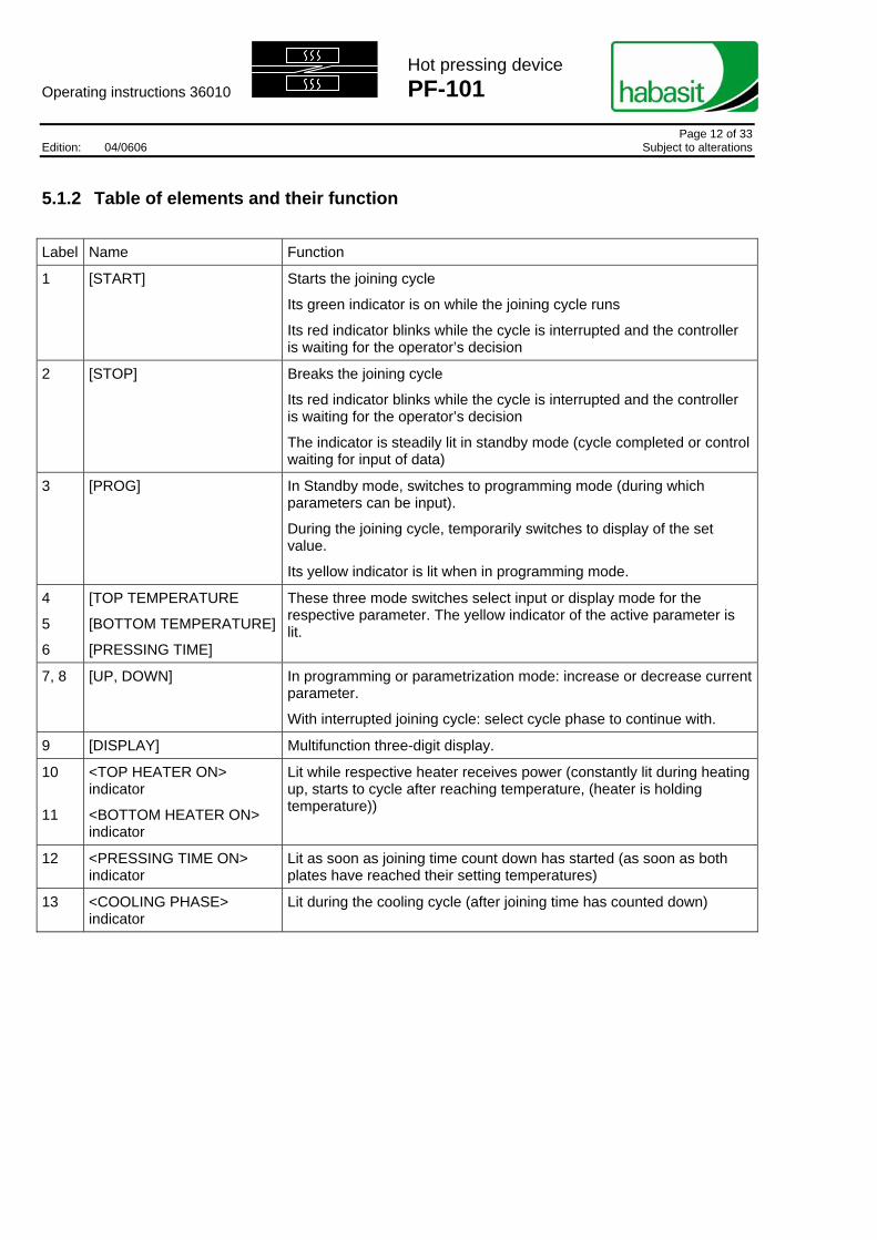
5.1.2 Table of elements and their function
Label Name Function
1 [START] Starts the joining cycle
Its green indicator is on while the joining cycle runs
Its red indicator blinks while the cycle is interrupted and the controller is waiting for the operator’s decision
2 [STOP] Breaks the joining cycle
Its red indicator blinks while the cycle is interrupted and the controller is waiting for the operator’s decision
The indicator is steadily lit in standby mode (cycle completed or control waiting for input of data)
3 [PROG] In Standby mode, switches to programming mode (during which parameters can be input).
During the joining cycle, temporarily switches to display of the set value.
Its yellow indicator is lit when in programming mode.
4
5
6
[TOP TEMPERATURE
[BOTTOM TEMPERATURE]
[PRESSING TIME]
These three mode switches select input or display mode for the respective parameter. The yellow indicator of the active parameter is lit.
7, 8 [UP, DOWN] In programming or parametrization mode: increase or decrease current parameter.
With interrupted joining cycle: select cycle phase to continue with.
9 [DISPLAY] Multifunction three-digit display.
10
11
<TOP HEATER ON> indicator
<BOTTOM HEATER ON> indicator
Lit while respective heater receives power (constantly lit during heating up, starts to cycle after reaching temperature, (heater is holding temperature))
12 <PRESSING TIME ON> indicator
Lit as soon as joining time count down has started (as soon as both plates have reached their setting temperatures)
13 <COOLING PHASE> indicator
Lit during the cooling cycle (after joining time has counted down)
Operating instructions 36010
Hot pressing device PF-101
Page 13 of 33 Edition: 04/0606 Subject to alterations
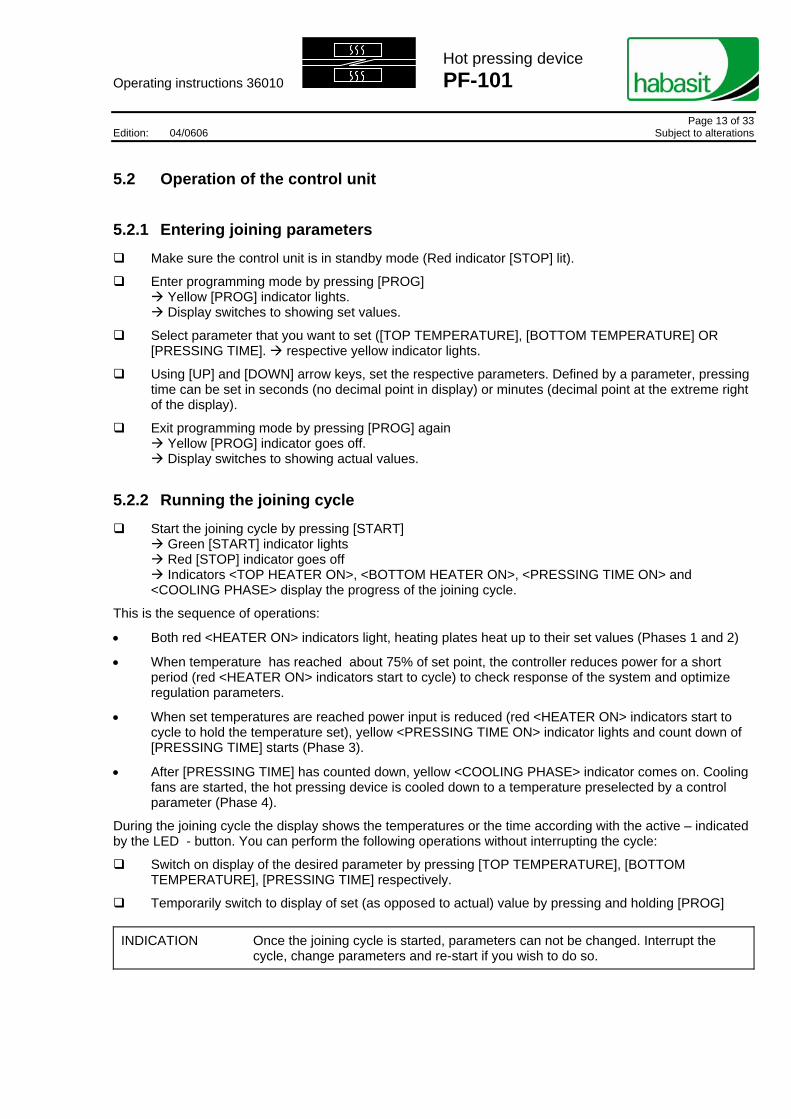
5.2 Operation of the control unit
5.2.1 Entering joining parameters
Make sure the control unit is in standby mode (Red indicator [STOP] lit).
Enter programming mode by pressing [PROG] Yellow [PROG] indicator lights. Display switches to showing set values.
Select parameter that you want to set ([TOP TEMPERATURE], [BOTTOM TEMPERATURE] OR [PRESSING TIME]. respective yellow indicator lights.
Using [UP] and [DOWN] arrow keys, set the respective parameters. Defined by a parameter, pressing time can be set in seconds (no decimal point in display) or minutes (decimal point at the extreme right of the display).
Exit programming mode by pressing [PROG] again Yellow [PROG] indicator goes off. Display switches to showing actual values.
5.2.2 Running the joining cycle
Start the joining cycle by pressing [START] Green [START] indicator lights Red [STOP] indicator goes off Indicators <TOP HEATER ON>, <BOTTOM HEATER ON>, <PRESSING TIME ON> and
<COOLING PHASE> display the progress of the joining cycle.
This is the sequence of operations:
• Both red <HEATER ON> indicators light, heating plates heat up to their set values (Phases 1 and 2)
• When temperature has reached about 75% of set point, the controller reduces power for a short period (red <HEATER ON> indicators start to cycle) to check response of the system and optimize regulation parameters.
• When set temperatures are reached power input is reduced (red <HEATER ON> indicators start to cycle to hold the temperature set), yellow <PRESSING TIME ON> indicator lights and count down of [PRESSING TIME] starts (Phase 3).
• After [PRESSING TIME] has counted down, yellow <COOLING PHASE> indicator comes on. Cooling fans are started, the hot pressing device is cooled down to a temperature preselected by a control parameter (Phase 4).
During the joining cycle the display shows the temperatures or the time according with the active – indicated by the LED - button. You can perform the following operations without interrupting the cycle:
Switch on display of the desired parameter by pressing [TOP TEMPERATURE], [BOTTOM TEMPERATURE], [PRESSING TIME] respectively.
Temporarily switch to display of set (as opposed to actual) value by pressing and holding [PROG]
INDICATION Once the joining cycle is started, parameters can not be changed. Interrupt the cycle, change parameters and re-start if you wish to do so.

Operating instructions 36010
Hot pressing device PF-101
Page 14 of 33 Edition: 04/0606 Subject to alterations
5.2.3 Interrupting the joining cycle
When the joining cycle is interrupted with the [STOP], button, various courses of action can be taken. Which ones are possible depends on the current phase of the joining cycle:
Ph2Ph1 Ph3 Ph4
Press [STOP] to interrupt the joining cycle. Red [STOP] and green [START] indicators blink. Power to all components of the hot pressing device is shut off [no cooling, no heating] The display shows the phase of the joining cycle to which the control will proceed when [START] is
pressed.
Select the desired phase with the [UP] and [DOWN] arrow keys.
Resume the cycle in the selected phase by pressing [START]
or
Leave the joining cycle altogether by pressing [STOP] again. In this case the press has to cool down on its own.
So the following exit paths are possible:
• Phase 1 (heating up, below cooling end-temperature) to Standby
• Phase 2 (heating up, above cooling end-temperature) to Phase 4 or Standby
• Phase 3 (count down of pressing time) to Phase 4 or Standby
• Phase 4 (cooling) to Standby
CAUTION Opening the press before cooling down temperature is reached may have a negative impact on joining quality.

Operating instructions 36010
Hot pressing device PF-101
Page 15 of 33 Edition: 04/0606 Subject to alterations
5.3 Parameterization of the control unit
Some of the parameters determining the behavior of the control unit can be set by the user. The sequence for this is as follows:
With the control unit in standby mode, press (and keep pressed) the [PROG] key for 5 seconds. -> The display shows: PAS
Press the [PROG] key again -> The display shows: 0
With the [UP] and [DOWN] arrow keys select the value 55
Press [PROG] again. -> The display shows the ID of the first parameter: SPr (Set point for stop cooling). See table below about parameter IDs and their meanings.
Press [PROG] again to see the value of this parameter: -> current value of this parameter is displayed: 50 (This is the default, you may see something different). See table below as to how to interpret these values.
Change the value with the [UP] and [DOWN] arrow keys.
Scroll down through the list with the [PROG] key. The sequence of display is: Parameter ID parameter value next parameter ID parameter value ...
Each time a value is displayed you can set it using the [UP] and [DOWN] arrow keys.
To exit the setting mode:
Using the [PROG] key scroll all the way down through the parameter list, or
Do nothing for 30 s: the control unit falls back to standby mode automatically.

Operating instructions 36010
Hot pressing device PF-101
Page 16 of 33 Edition: 04/0606 Subject to alterations
5.3.1 List of user accessible parameters Ord. Vis.
Joining data / parameter PROGRAMMING CONFIGURATION
From To Resolution /measuring unit
cod.ID From To Default Resolution/ measuring unit
Set-Point Temp. Upper plate dn1 UP1 1 / °C - Set-Point Temp. Lower plate dn2 UP2 1 / °C - Preset joining time 0 999 1 / sec
(Unt=1) -
1 / min (Unt=60)
Password to access to configuration parameters PAS - - 55 1 / unit 1 Set-point stop cooling SPr 20 70 50 1 / °C 2 Joining time scale (sec = 1; minutes = 60) Unt 1 60 1 3 Off-Set NTC upper plate OF1 -20 20 0 0,5 / °C 4 Off-Set NTC lower plate OF2 -20 20 0 0,5 / °C 5 Air blowing electrovalve ON/OFF (for future use) Ar 1 0 0 6 Air blowing time (seconds) (for future use) SAr 0 500 180 1 / seconds 7 Serial address for RS net. (for future use) Add 1 32 1 1 / unit 8 Upper plate: Temperature set point upper limit UP1 100 200 200 1 / °C 9 Upper plate: Temperature set point lower limit dn1 20 50 50 1 / °C 10 Lower plate: Temperature set point upper limit UP2 100 200 200 1 / °C 11 Lower plate: Temperature set point lower limit dn2 20 50 50 1 / °C

Operating instructions 36010
Hot-pressing device PF-101
Page 17 of 33 Edition: 04/0606 Subject to alterations
6. Service
6.1 Maintenance
Keep the whole hot pressing device clean. Heating plates (10,11) set up plate (3) and cover plate (5) are prone to soiling by melted material; keep clean and smooth at all times
WARNING For cleaning with a cloth moistened with water or solvent, the press must be disconnected from the power supply. Do not reconnect to the power supply until the press is completely dry.
Periodically inspect the power supply cable and connector plug for defects (insulation damage, etc.) and rectify or replace with the correct type where necessary.
6.2 Measuring of the plate temperature Check the correct process temperature of heating plates (10, 11) once a month:
Carry out this check in an interior room in a draft-free environment with an ambient temperature of between 18 °C / 64 °F and 25 °C / 77 °F
Remove set up plate (3) and cover plate (5). Place heat-resistant silicone foam rubber pad in the hot pressing device.
Close hot pressing device and tighten closing screws (6, 7) lightly.
Set a temperature of 180 °C / 356 °F and a joining time of 60 min, start heating.
10 min after set temperature is reached, open press, slightly lift off top heating plate and place the sensor of a precision thermometer on the silicon foam rubber pad exactly in the center of the heating plate.
Close press (without applying pressure). Read temperature after about 3 min.
Repeat with the bottom heating plate (place sensor underneath the silicone foam rubber pad in the center of the heating plate). The measured temperature should read 180 °C +/- 2 °C / 356 °F +/- 3.6 °F (including the measuring accuracy of max +/- 1 °C / 1.8 °F of the instrument).
Stop heating cycle by selecting the cooling phase (Ph4) with [STOP] and [UP] keys.

Operating instructions 36010
Hot-pressing device PF-101
Page 18 of 33 Edition: 04/0606 Subject to alterations
6.3 Adjustment of the temperature
CAUTION This procedure implies an adjustment of parameter settings. It must be done by authorized, skilled personnel.
If the measured temperatures (top or bottom) deviates from what is indicated on display, the control is to be adjusted as follows:
In standby mode, press [PROG] for more than 5 seconds; then enter password according to procedure description. (See separate parameterization instructions in chapter 5.3.)
Select the offset temperature parameter for the desired plate by scrolling parameters with [PROG]
Enter a value according to the following rules:
if the measured temperature is more than temperature displayed, a negative value corresponding to 2 x the measured difference (resolution of parameter is 0.5°C);
if the measured temperature is less than temperature displayed, a positive value corresponding to 2 x the measured difference.
Complete the scrolling of all parameters until the system exits automatically from parameter setting procedure.
6.4 Replacement of the power cord
Check power cord and connecting cables (14, 15) periodically. In case of damage replace with the same type (see spare parts list).
WARNING All work on the hot-pressing device involving electrical parts has to be carried out by the respective specialists only. Observe your local laws concerning required training of such personnel.

Operating instructions 36010
Hot-pressing device PF-101
Page 19 of 33 Edition: 04/0606 Subject to alterations
6.5 Replacement of the transformer safety fuse
WARNING All work on the hot-pressing device involving electrical parts has to be carried out by the respective specialists only. Observe your local laws concerning required training of such personnel.
Follow these instructions to replace the internal safety fuse (see illustration below):
Fuse technical data:
- type 5x20
- 500 mA
- 250V / T
WARNING Disconnect the power cord before opening the control unit!
Open the control unit by removing the 4 screws on back cover.
Locate the fuse (near the transformer) according to illustration.
With a screwdriver, open the fuse holder cap and remove the fuse.
Replace fuse and close the fuse holder and close the control unit cover.
Fuse holder

Operating instructions 36010
Hot-pressing device PF-101
Page 20 of 33 Edition: 04/0606 Subject to alterations
7. Illustrations
7.1 Overview
16
121 7
2
3
6
4 5
14 15
Legend 1 Top press part 2 Bottom press part 3 Set up plate 4 Clamping bar 5 Cover plate 6 Front closing screw 7 Rear closing screw 12 Control unit 14, 15 Connecting cables 16 Handles

Operating instructions 36010
Hot-pressing device PF-101
Page 21 of 33 Edition: 04/0606 Subject to alterations
7.2 Press
1
3
2
4 5
6 7 8 9 13 14
15
19 17
18
Legend (1) Top press part (2) Bottom press part (3) Set-up plate (4) Clamping bar (5) Cover plate (6) Front closing screw (7) Rear closing screw (8) Top pressure indicator
(9) Lateral pressure indicator (13) Cooling fan (14) Connecting cable, top (15) Connecting cable, bottom (17) Attachment points (18) Clamping screw (19) Hinge pin

Operating instructions 36010
Hot-pressing device PF-101
Page 22 of 33 Edition: 04/0606 Subject to alterations
7.3 Press open
3 4
18
10
2
20
11
16
1
6
7
5
Legend (1) Top press part (2) Bottom press part (3) Set-up plate (4) Clamping bar (swung out) (5) Cover plate (6) Front closing screw (flipped down)
(7) Rear closing screw (10) Top heating plate (11) Bottom heating plate (18) Clamping screw (flipped down) (20) Removable rubber feet

Operating instructions 36010
Hot-pressing device PF-101
Page 23 of 33 Edition: 04/0606 Subject to alterations
8. Technical data
8.1 Data
Belt / tape width max. (Flexproof) [mm] [in.] 100 4.0
Belt / tape width max. (Thermofix) [mm] [in.] 130 5.11
Belt / tape thickness max. [mm] [in.] 6 0.24
Max. finger length [mm] [in.] 80/120 3.2/4.8
Min. endless belt / tape length [mm] [in.] 460 18
Pressure on belt [bar] [lbs./sq.in.] 1...2 14.5 ... 29
Pressing temperature max [°C] [°F] 200 392
Power consumption [W] 2 x 350
Voltage (PF-101.6) [V~] 1 x 120
Voltage (PF-101.8) [V~] 1 x 230
Dimensions (press) (L x W x H) [mm] [in.] 260 x 190 x 145 10.3 x 7.5 x 5.7
Dimensions (control unit) (L x W x H) [mm] [in.] 260 x 135 x 60 10.3 x 5.3 x 2.4
Weight (press) [kg] [lbs.] 3.7 8.3
Weight (control unit) [kg] [lbs.] 1.85 4.1
8.2 Identification labels
The following illustrations show the identification labels applied on the press (PF-101) and control unit (PFR-101). Remember that in case the device needs to be repaired by our service centers, all data of the labels must be furnished.
CAUTION Do not remove identification labels! Warranty is void if missing.
00050017
00050017

Operating instructions 36010
Hot-pressing device PF-101
Page 24 of 33 Edition: 04/0606 Subject to alterations
9. List of Habasit belt types that can be Thermofix joined with PF-101
Because of the limited pressure range of the PF-101, this hot-pressing device is not recommended for Thermofix joining of power transmission belts for high power applications. The following belts may be Thermofix joined with PF-101:
All conveyor belts that are Thermofix joined with Polycol A+B. (Therefore, all thermoplastic Food Standard, Extraline and High duty conveyor and processing belts that are normally joined with the Flexproof joining method.) Plus the following Habasit belt products:
Spindle tapes HS-4, HS-5, HS-55, F-0, TS-5, TS-10, TS-55
High duty conveyor and processing belts
HAG-12E, HAL-12E, HAM-5P, HAR-12E, HAT-8P, HAT-12P, HNA-12E, HNA-18P, HNI-5P, HNI-5PE, HNU-8P
Extraline processing belts EAB-3G, EAT-8P, ENI-5P, ENI-10E, ENI-12P
Machine tapes A-1, F-1 (for thermoplastic machine tapes use Flexproof, or, where admissible, Quickmelt)
Folder gluer belts S-10/15, S-18/20
Food conveyor and processing belts
FNI-2E, FNT-2M, FNT-5P
CAUTION Make sure that you always use good pressure equalization when using the press for Thermofix joining. (A pad of HAT-12P has proven to serve this purpose well.)

Operating instructions 36010
Hot-pressing device PF-101
Page 25 of 33 Edition: 04/0606 Subject to alterations
10 Drawings 10.1 Connection diagram

Operating instructions 36010
Hot-pressing device PF-101
Page 26 of 33 Edition: 04/0606 Subject to alterations
10.2 Assembly of press
INDICATION Labels on the following drawings do not correspond to the labels given to parts in the photographic illustrations and the text. They serve only to identify all parts in the parts list.

Operating instructions 36010
Hot-pressing device PF-101
Page 27 of 33 Edition: 04/0606 Subject to alterations

Operating instructions 36010
Hot-pressing device PF-101
Page 28 of 33 Edition: 04/0606 Subject to alterations
10.3 Set-up plate

Operating instructions 36010
Hot-pressing device PF-101
Page 29 of 33 Edition: 04/0606 Subject to alterations
10.4 Control unit
PROG.

Operating instructions 36010
Hot-pressing device PF-101
Page 30 of 33 Edition: 04/0606 Subject to alterations
10.5 Preparation scheme for Flexproof fingers with 120 mm
Lower heat equalizing plate
Upper heat equalizing plate
9 Upp
8 Hea
7 Silic
6 Belt
5 Silic
4 Moll
3 Set-
2 Hea
1 Low
9
8 7 6
5 4 3
2
1
er heating plate
t equalizing plate - 2mm thick, L = 140 mm
one paper / meltable foil / etc.
with 120 mm Flexproof fingers
one paper
eton
up plate in fiberglass - 3mm thick
t equalizing plate - 2mm thick, L = 160mm
er heating plate

Operating instructions 36010 Appendix
Checklist preventive maintenance Hot-pressing device PF-101
Page 31 of 33 Edition: 04/0606 Subject to alterations
Responsible persons: A: Machine Operator B: Maintenance Technician Work to be carried out Performance Spares number(see operating instructions No. 36010 for further information and reference numbers) periodically (monthly) Evaluation criterion Daily 1 6 Remarks1. Cleaning 1.1 Clean the press after use, remove residual deposits A 2. Inspect the connector cable 2.1 Examine the cable and connector plug for defects B damaged insulation,
defective couplings 3. Measurement of the heater plate temperature 3.1 Proceed as detailed in operating instructions 36010, Section 6.2 B
Remarks and notes:

Operating instructions 36010 Appendix
Report sheet preventative maintenance Hot-pressing device PF-101
Page 32 of 33 Edition: 04/0606 Subject to alterations
Machine type:
Machine no.: Date of first placing in operation: Actions to be performed – see checklist Next Performed Next Performed Next Performed Next Performed(daily work not recorded) Check Initials Date Check Initials Date Check Initials Date Check Initials Date2.1 Inspect the cable for damage
3.1 Measure the heater plate temperature
Observations, repairs:

Operating instructions 36010 Appendix
Hot-pressing device PF-101
Page 33 of 33 Edition: 04/0606 Subject to alterations
Product liability, application considerations If the proper selection and application of Habasit products are not recommended by an authorized Habasit sales specialist, the selection and application of Habasit products, including the related area of product safety, are the responsibility of the customer. All indications / information are recommendations and believed to be reliable, but no representations, guarantees, or warranties of any kind are made as to their accuracy or suitability for particular applications. The data provided herein are based on laboratory work with small-scale test equipment, running at standard conditions, and do not necessarily match product performance in industrial use. New knowledge and experiences can lead to modifications and changes within a short time without prior notice.
BECAUSE CONDITIONS OF USE ARE OUTSIDE OF HABASIT’S AND ITS AFFILIATED COMPANIES CONTROL, WE CANNOT ASSUME ANY LIABILITY CONCERNING THE SUITABILITY AND PROCESS ABILITY OF THE PRODUCTS MENTIONED HEREIN. THIS ALSO APPLIES TO PROCESS RESULTS / OUTPUT / MANUFACTURING GOODS AS WELL AS TO POSSIBLE DEFECTS, DAMAGES, CONSEQUENTIAL DAMAGES, AND FURTHER-REACHING CONSEQUENCES.