Host Port Interface - Florida Institute of Technology
30
Host Port Interface Introduction This module discusses the Host Port Interface (HPI). First, a brief overview of the HPI will discuss the reasons for including it on these devices and some of the benefits that it provides. Next, we present examples to help you understand the terminology, capabilities, and basic flow of the HPI. The module also includes a discussion of the HPI’s other features. The module ends with a basic comparison of the HPI to the ‘C6202/03/04 Expansion Bus. By the end of this module you will have a good understanding of the HPI and the Expansion Bus and how they provide a capable interface to industry standard hosts processors. Learning Objectives Objectives HPI Overview HPI on the DSK Host Software Example HPI Hardware Description Optional Discussions T TO Technical Training Organization C6000 Integration Workshop - Host Port Interface 16 - 1
Transcript of Host Port Interface - Florida Institute of Technology

Host Port Interface
Introduction This module discusses the Host Port Interface (HPI). First, a brief overview of the HPI will discuss the reasons for including it on these devices and some of the benefits that it provides. Next, we present examples to help you understand the terminology, capabilities, and basic flow of the HPI. The module also includes a discussion of the HPI’s other features. The module ends with a basic comparison of the HPI to the ‘C6202/03/04 Expansion Bus. By the end of this module you will have a good understanding of the HPI and the Expansion Bus and how they provide a capable interface to industry standard hosts processors.
Learning Objectives
ObjectivesHPI OverviewHPI on the DSK Host Software Example HPI Hardware Description Optional Discussions
T TOTechnical Training
Organization
C6000 Integration Workshop - Host Port Interface 16 - 1

HPI Overview
Chapter Topics Host Port Interface...................................................................................................................................16-1
HPI Overview ........................................................................................................................................16-3 HPI and the DSK ...................................................................................................................................16-5 HPI – Host Software Example ...............................................................................................................16-6 HPI Hardware Description....................................................................................................................16-7
Setting Up the Control Register (HPIC) ............................................................................................16-7 Setting Up the Address Register......................................................................................................16-10 Writing a 32-bit Value.....................................................................................................................16-12 Reading a 32-bit Value ....................................................................................................................16-15 Reading Multiple Values .................................................................................................................16-18 HPI Pins...........................................................................................................................................16-20
HSTRB .......................................................................................................................................16-21 HAS.............................................................................................................................................16-21 An Example Interface..................................................................................................................16-22
HPI Related Registers (Optional Topic) ..............................................................................................16-23 HPIC................................................................................................................................................16-23 CSL API for the Host Port Interface................................................................................................16-24
Expansion Bus (Optional Topic)..........................................................................................................16-25 XB Summary ...................................................................................................................................16-30
16 - 2 C6000 Integration Workshop - Host Port Interface

HPI Overview
HPI Overview The HPI provides an economical 16-bit parallel port for interfacing a ‘C6x to host processors, other ‘C6xs, and PCI bridge chips. This bus is in addition to the ‘C6x external bus (EMIF) and multi-channel serial ports, which may be dedicated to memory and A/Ds or codecs.
Why HPI?
μCμC ‘C6x‘C6x
Ser. Port
32|| Bus
Ded. Bus
Dedicated to memory access
Dedicated to Codecs and A/D’s
T TOTechnical Training
Organization
A dedicated bus is used to transfer data to or from an address in the ‘C6x memory map. The HPI has a 32-bit registers for each control, address, and data. The HPIC is used to control HPI transfers. The HPIA is the address for the read or write operation. The HPID is the data register.
What are the requirements for the dedicated bus?1. Address2. Data3. Control
What are the requirements for the dedicated bus?1. Address2. Data3. Control
HPI Bus
HPI Overview
μC μC ‘C6x‘C6xHPIHPIC
HPIA
HPID
DMAAux. Ch.
Addr.
Data
Memory
...
T TOTechnical Training
Organization
The HPI is connected to the ‘C6x memory via the DMA Auxiliary Channel, which gives the host access to the entire ‘C6x memory map. The Auxiliary Channel is the fifth channel of the DMA, and it is dedicated to the HPI.
C6000 Integration Workshop - Host Port Interface 16 - 3

HPI Overview
Since the HPI bus is only 16-bits wide, each data transfer to an HPI register requires two read or write operations. Although this is slower, it lowers the pin count of the device.
HPI Bus
HPI Overview
Since the HPI bus (HD) is only 16 bits wide, each read/write requires two operations.
Since the HPI bus (HD) is only 16 bits wide, each read/write requires two operations.
μC μC ‘C6x‘C6xHPIHPIC
HPIA
HPID
DMAAux. Ch.
Addr.
Data
Memory
...
16
T TOTechnical Training
Organization
The HPI provides a simple slave interface to a host, which serves as the master. It gives the host processor access to entire memory map of the ‘C6x, including the internal memories, the EMIF, and the peripheral control registers.
Why HPI for Communication?Give host control of the transferAllow host to access the entire C6000 memory map Additional parallel bus for data exchange between a host and the C6000Provide glueless interface to many different types of hosts
T TOTechnical Training
Organization
16 - 4 C6000 Integration Workshop - Host Port Interface

HPI and the DSK
HPI and the DSK Host → DSK Communications
The C6713 DSK has a HPI connector which brings out the pins of the Host Port InterfaceOn the C6416 DSK, this connector contains the muxed HPI/PCI pinsAlso shown, the JTAG emulation connections
DSP
JTAGEmulation
Port
HPI connector
USB
..............
JTAG
....... .............. .......
T TOTechnical Training
Organization
C6000 Integration Workshop - Host Port Interface 16 - 5

HPI – Host Software Example
HPI – Host Software Example Some Ideas for Host Interface API
C6X_open( ) Open a connection to the C6000C6X_close( ) Close a connection to the C6000C6X_resetBoard( ) Reset the entire boardC6X_resetDsp( ) Reset only the DSP on the boardC6X_dspImageLoad( ) Load a DSP image (COFF) to DSP memoryC6X_memRead( ) Read DSP memory via the HPIC6X_memWrite( ) Write to DSP memory via the HPIC6X_ctrlRead( ) Read HPI control registerC6X_ctrlWrite( ) Write to HPI control registerC6X_generateInt( ) Generate a DSP interruptC6X_isr( ) Respond to host interrupt (HINT) from DSP
Here are some ideas for the host software (and hardware) functionality you might want to build into your systemThese routines could be combined to create more advanced host functions (like routines for setting up the EDMA and such)Unfortunately, we cannot provide these functions for you, as they must be written specific to the hardware of your hostT TO
Technical Training Organization
16 - 6 C6000 Integration Workshop - Host Port Interface

HPI Hardware Description
HPI Hardware Description
Setting Up the Control Register (HPIC) The first step in using the HPI is to setup the HPIC. This register contains the halfword ordering bit, or HWOB. HWOB sets the endianness for HPI transfers. If HWOB=0, then the first halfword transferred will be put in the MSBs. If HWOB=1, then the first halfword transferred will be put in the LSBs.
Setup HPI Control Register
HWOB0 - Big Endian1 - Little Endian
HWOB0 - Big Endian1 - Little Endian
HWOBreserved015 5
HWOBreserved1631 21
Setup the HPI Control register (HWOB-bit) to specify which 16-bits (upper or lower) are transferred first.Similar to little/big endian.Order doesn’t matter whenwriting to HPIC as the fieldsare aliased to both halves.
T TOTechnical Training
Organization
Writing to this register is selected by the HCNTL(1:0) pins. These pins select the register that the host wants to read or write. They are usually connected to address pins on the host side.
Setup HPIC
1. Use HCNTL[1:0] = 00b to enable access to HPIC1. Use HCNTL[1:0] = 00b to enable access to HPIC
μCμC ‘C6x‘C6xHPI
DMAAux. Ch.
Addr.
Data
2HCNTL
HPID
HPIA
Memory
...
HD16
HPIC
HCNTL ValuesHCNTL ValuesHCNTL1 HCNTL0 Description
0 0 HPIC0 1 HPIA1 0 HPID (HPIA++ 1 1 HPID
)
T TOTechnical Training
Organization
C6000 Integration Workshop - Host Port Interface 16 - 7

HPI Hardware Description
The HR/W pin determines the direction of the transfer.
Setup HPIC
μCμC ‘C6x‘C6xHPI
DMAAux. Ch.
Addr.
Data
2HCNTL
HPID
HPIA
Memory
...
HD16
HPIC
HR/W
1. Use HCNTL[1:0] = 00b to enable access to HPICHR/W to write (0). HD = ctrl bits (HWOB= xxx1)
1. Use HCNTL[1:0] = 00b to enable access to HPICHR/W to write (0). HD = ctrl bits (HWOB= xxx1)
T TOTechnical Training
Organization
HHWIL identifies which halfword is being transferred. For the first halfword of a transfer, HHWIL will be low. For the second halfword, HHWIL will be high. Remember that the HWOB bit in the HPIC determines if the first halfword is put in the LSBs (little endian) or the MSBs (big endian). What happens to HPIC when it is written for the first time? Is the value written to the LSBs or the MSBs? It turns out that HPIC is really only 16 bits, and the LSBs and MSBs are the same.
Setup HPIC - 1
μCμC ‘C6x‘C6xHPI
DMAAux. Ch.
Addr.
DataHPID
HPIA
Memory
...
HD16
HPIC
HR/W
HHWIL
1. Use HCNTL[1:0] = 00b to enable access to HPICHR/W to write (0), HD = ctrl bits (HWOB = xxx1)HHWIL = 0 indicates first halfword transfer
1. Use HCNTL[1:0] = 00b to enable access to HPICHR/W to write (0), HD = ctrl bits (HWOB = xxx1)HHWIL = 0 indicates first halfword transfer
2HCNTL
T TOTechnical Training
Organization
16 - 8 C6000 Integration Workshop - Host Port Interface

HPI Hardware Description
The HSTRB signal initiates the transfer. At the falling edge of HSTRB, the other control signals are sampled and the write operation becomes active. The value on the HD pins is latched into the HPIC register at the rising edge of HSTRB. The first half of the 32-bit transfer is complete.
HSTRB - 2
μCμC ‘C6x‘C6xHPI
DMAAux. Ch.
Addr.
DataHPID
HPIA
Memory
...
HPIC
HSTRB
1. Use HCNTL[1:0] = 00b to enable access to HPICHR/W to write (0). HD = ctrl bits (HWOB = xxx1)HHWIL = 0 indicates first halfword transfer
2. HSTRB to indicate active
1. Use HCNTL[1:0] = 00b to enable access to HPICHR/W to write (0). HD = ctrl bits (HWOB = xxx1)HHWIL = 0 indicates first halfword transfer
2. HSTRB to indicate active
HD16
HR/W
HHWIL
2HCNTL
xxx1
T TOTechnical Training
Organization
For the second half of the transfer, some of the conrol pins (HCNTL, HR/W) do not need to change. In the case of HPIC, HD does not change. HHWIL will transition high to indicate the second half of a transfer.
Setup HPIC - 3
μCμC ‘C6x‘C6xHPI
DMAAux. Ch.
Addr.
DataHPID
HPIA
Memory
...
HPIC
3. Use HCNTL[1:0] = 00b to enable access to HPICHR/W to write (0). HD = ctrl bits (HWOB = xxx1)HHWIL = 1 indicates second halfword transfer
3. Use HCNTL[1:0] = 00b to enable access to HPICHR/W to write (0). HD = ctrl bits (HWOB = xxx1)HHWIL = 1 indicates second halfword transfer
HD16
HR/W
HHWIL
2HCNTL
xxx1
T TOTechnical Training
Organization
C6000 Integration Workshop - Host Port Interface 16 - 9

HPI Hardware Description
The falling edge of HSTRB indicates an active transfer. At the second rising edge of HSTRB, the transfer is complete and HPIC is setup.
Setup HPIC - 4
μCμC ‘C6x‘C6xHPI
DMAAux. Ch.
Addr.
DataHPID
HPIA
Memory
...
HPIC
HSTRB
3. Use HCNTL[1:0] = 00b to enable access to HPICHR/W to write (0). HD = ctrl bits (HWOB = xxx1)HHWIL = 1 indicates second halfword transfer
4. HSTRB to indicate active
3. Use HCNTL[1:0] = 00b to enable access to HPICHR/W to write (0). HD = ctrl bits (HWOB = xxx1)HHWIL = 1 indicates second halfword transfer
4. HSTRB to indicate active
HD16
HR/W
HHWIL
2HCNTL
xxx1xxx1
T TOTechnical Training
Organization
Setting Up the Address Register The next step is for the host to setup the address in the HPIA register. This transfer is very similar to the HPIC setup. HCNTL selects the HPIA register. HHWIL is low for the first half of a transfer. HR/W is low to indicate a write operation. Finally, HD has the lower 16-bits of the address.
Setup HPIA - 1
μC
Write8000_0000
toHPIA
μC
Write8000_0000
toHPIA
‘C6x‘C6xHPI
DMAAux. Ch.
Addr.
DataHPID
HPIA
Memory
...
HPIC
1. Use HCNTL[1:0] = 01b to enable access to HPIAHR/W to write (0), HD = 0000HHWIL = 0 indicates first halfword transfer
1. Use HCNTL[1:0] = 01b to enable access to HPIAHR/W to write (0), HD = 0000HHWIL = 0 indicates first halfword transfer
HR/W
HHWIL
HD16
2HCNTL
xxx1xxx1
T TOTechnical Training
Organization
16 - 10 C6000 Integration Workshop - Host Port Interface

HPI Hardware Description
The falling edge of HSTRB indicates an active transfer. Since HWOB=1 indicating little endian, the value of the HD pins is copied into the LSBs of HPIA.
Setup HPIA - 2
μC
Write8000_0000
toHPIA
μC
Write8000_0000
toHPIA
‘C6x‘C6xHPI
DMAAux. Ch.
Addr.
DataHPID
HPIA
Memory
...
HPIC
HSTRB
1. Use HCNTL[1:0] = 01b to enable access to HPIAHR/W to write (0). HD = 0000HHWIL = 0 indicates first halfword transfer
2. HSTRB to indicate active
1. Use HCNTL[1:0] = 01b to enable access to HPIAHR/W to write (0). HD = 0000HHWIL = 0 indicates first halfword transfer
2. HSTRB to indicate active
HD16
HR/W
HHWIL
2HCNTL
xxx1xxx1
0000
T TOTechnical Training
Organization
For the second half of the transfer, HCNTL and HR/W do not change. HHWIL transitions high to indicate that this is the second part of a transfer, and the host has changed the HD pins to the upper 16-bits of the address.
Setup HPIA - 3
μC
Write8000_0000
toHPIA
μC
Write8000_0000
toHPIA
‘C6x‘C6xHPI
DMAAux. Ch.
Addr.
DataHPID
HPIA
Memory
...
HPIC
3. Use HCNTL[1:0] = 01b to enable access to HPIAHR/W to write (0). HD = 8000HHWIL = 1 indicates second halfword transfer
3. Use HCNTL[1:0] = 01b to enable access to HPIAHR/W to write (0). HD = 8000HHWIL = 1 indicates second halfword transfer
HD16
HR/W
HHWIL
2HCNTL
xxx1xxx1
0000
T TOTechnical Training
Organization
The falling edge of HSTRB indicates an active transfer and the address is written to the HPIA.
C6000 Integration Workshop - Host Port Interface 16 - 11
HPI Hardware Description
Setup HPIA - 4
μC
Write8000_0000
toHPIA
μC
Write8000_0000
toHPIA
‘C6x‘C6xHPI
DMAAux. Ch.
Addr.
DataHPID
HPIA
Memory
...
HPIC
HSTRB
3. Use HCNTL[1:0] = 01b to enable access to HPIAHR/W to write (0). HD = 8000HHWIL = 1 indicates second halfword transfer
4. HSTRB to indicate active
3. Use HCNTL[1:0] = 01b to enable access to HPIAHR/W to write (0). HD = 8000HHWIL = 1 indicates second halfword transfer
4. HSTRB to indicate active
HD16
HR/W
HHWIL
2HCNTL
xxx1xxx1
00008000
T TOTechnical Training
Organization
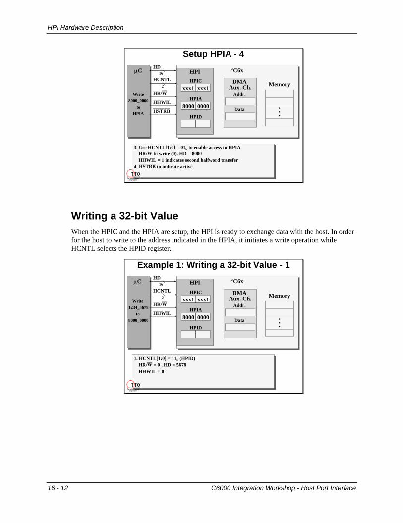
Writing a 32-bit Value When the HPIC and the HPIA are setup, the HPI is ready to exchange data with the host. In order for the host to write to the address indicated in the HPIA, it initiates a write operation while HCNTL selects the HPID register.
Example 1: Writing a 32-bit Value - 1
1. HCNTL[1:0] = 11b (HPID)HR/W = 0 , HD = 5678HHWIL = 0
1. HCNTL[1:0] = 11b (HPID)HR/W = 0 , HD = 5678HHWIL = 0
μC
Write 1234_5678
to 8000_0000
μC
Write 1234_5678
to 8000_0000
‘C6x‘C6xHPI
HPID
DMAAux. Ch.
Addr.
DataHHWIL
2HCNTL
HPIA8000 0000
Memory
...
HD16
HR/W
HPICxxx1xxx1
T TOTechnical Training
Organization
16 - 12 C6000 Integration Workshop - Host Port Interface

HPI Hardware Description
The falling edge of HSTRB initiates the transfer, and the rising edge latches the data into the lower 16-bits of the HPID register.
Example 1: Writing a 32-bit Value - 2
μC
Write 1234_5678
to 8000_0000
μC
Write 1234_5678
to 8000_0000
‘C6x‘C6xHPI
HPID5678
DMAAux. Ch.
Addr.
DataHHWIL
2HCNTL
HPIA8000 0000
Memory
...
HD16
HSTRB
HR/W
HPICxxx1xxx1
1. HCNTL[1:0] = 11b (HPID)HR/W = 0 , HD = 5678HHWIL = 0
2. HSTRB
1. HCNTL[1:0] = 11b (HPID)HR/W = 0 , HD = 5678HHWIL = 0
2. HSTRB
T TOTechnical Training
Organization
For the second half of the transfer, HHWIL transitions high, and the value of the HD pins changes to reflect the upper 16-bits of data.
Example 1: Writing a 32-bit Value - 3
3. HCNTL[1:0] = 11b (HPID)HR/W = 0Write value: HHWIL = 1, HD = 1234
3. HCNTL[1:0] = 11b (HPID)HR/W = 0Write value: HHWIL = 1, HD = 1234
μC
Write 1234_5678
to 8000_0000
μC
Write 1234_5678
to 8000_0000
‘C6x‘C6xHPI
HPID5678
DMAAux. Ch.
Addr.
DataHHWIL
2HCNTL
HPIA8000 0000
Memory
...
HD16
HR/W
HPICxxx1xxx1
T TOTechnical Training
Organization
HSTRB falls low to indicate an active transfer. At the rising edge of HSTRB, the data is latched into the HPID. The 32-bit transfer to the HPI is now complete, but has the data actually been written to the address?
C6000 Integration Workshop - Host Port Interface 16 - 13

HPI Hardware Description
Example 1: Writing a 32-bit Value - 4
3. HCNTL[1:0] = 11b (HPID)HR/W = 0Write value: HHWIL = 1, HD = 1234
4. HSTRB
3. HCNTL[1:0] = 11b (HPID)HR/W = 0Write value: HHWIL = 1, HD = 1234
4. HSTRB
μC
Write 1234_5678
to 8000_0000
μC
Write 1234_5678
to 8000_0000
‘C6x‘C6xHPI
HPID1234 5678
DMAAux. Ch.
Addr.
DataHHWIL
2HCNTL
HPIA8000 0000
Memory
...
HD16
HR/W
HPICxxx1xxx1
HSTRB
T TOTechnical Training
Organization
When HPID has been written, the HPI will signal the DMA Auxialiary Channel to transfer the data from the HPI to the address in the HPIA. Several factors affect the length of time that it will take for the DMA to complete this transfer. These include:
• Speed of the destination memory • Bus contention • DMA Auxiliary Channel Priority
If the time needed to transfer from the HPI to memory can vary, how does the host know when it can write a new value to the HPI? The HPI uses the HRDY pin to signal the host that it is busy with a current transfer. This prevents the host from overwriting information in the HPI. When HRDY is low, the HPI is ready. So, at the second rising edge of HSTRB, when all of the data is latched into the HPID, HRDY is asserted high (not ready) until the DMA has completed the transfer.
Example 1: Writing a 32-bit Value - 5
3. HCNTL[1:0] = 11b (HPID)HR/W = 0Write value: HHWIL = 1, HD = 1234
4. HSTRB5. HRDY high (not-ready) until DMA is finished
3. HCNTL[1:0] = 11b (HPID)HR/W = 0Write value: HHWIL = 1, HD = 1234
4. HSTRB5. HRDY high (not-ready) until DMA is finished
μC
Write 1234_5678
to 8000_0000
μC
Write 1234_5678
to 8000_0000
‘C6x‘C6xHPI
HPID1234 5678
DMAAux. Ch.
Addr.
DataHHWIL
2HCNTL
HPIA8000 0000
Memory
...
HD16
HSTRB
HRDY↑
HPIC
8000 0000
1234 5678
1234 5678
xxx1xxx1HR/W
T TOTechnical Training
Organization
HRDY is used more as a not-ready pin to state either data is not yet available on a read or the DMA hasn’t yet completed the write (thus freeing-up the HPID).
16 - 14 C6000 Integration Workshop - Host Port Interface

HPI Hardware Description
Reading a 32-bit Value The process for a host read operation with the HPI is similar to a write. If the HPIC and HPIA are setup, the host sets up the control pins for the first half of a read operation using appropriate values on HCNTL, HHWIL, and HR/W.
Example 2: Reading a 32-bit Value - 1
1. HCNTL[1:0] = 11b (HPID)HR/W = 1Read value: HHWIL = 0
1. HCNTL[1:0] = 11b (HPID)HR/W = 1Read value: HHWIL = 0
μC
Read 8000_0000
μC
Read 8000_0000
‘C6x‘C6xHPI
HPID
DMAAux. Ch.
Addr.
DataHHWIL
2HCNTL
HPIA8000 0000
Memory
...
HR/W
HPIC
1234 5678
xxx1xxx1
T TOTechnical Training
Organization
The falling edge of HSTRB initiates a read from the address in the HPIA register. This address is copied to the DMA Auxiliary Channel.
Example 2: Reading a 32-bit Value - 2
1. HCNTL[1:0] = 11b (HPID)HR/W = 1Read value: HHWIL = 0
2. HSTRB, HPIA is copied to DMA address
1. HCNTL[1:0] = 11b (HPID)HR/W = 1Read value: HHWIL = 0
2. HSTRB, HPIA is copied to DMA address
μC
Read 8000_0000
μC
Read 8000_0000
‘C6x‘C6xHPI
HPID
DMAAux. Ch.
Addr.
DataHHWIL
2HCNTL
HPIA8000 0000
Memory
...HSTRB
HPIC
1234 5678
xxx1xxx1HR/W
T TOTechnical Training
Organization
C6000 Integration Workshop - Host Port Interface 16 - 15

HPI Hardware Description
At this point, the HPI has to wait for the DMA to complete the transfer from memory to the HPID register. HRDY is asserted high to hold off the host until the data is written into the HPID.
Example 2: Reading a 32-bit Value - 3
1. HCNTL[1:0] = 11b (HPID)HR/W = 1Read value: HHWIL = 0
2. HSTRB, HPIA is copied to DMA address3. HRDY is asserted until HD = 5678
1. HCNTL[1:0] = 11b (HPID)HR/W = 1Read value: HHWIL = 0
2. HSTRB, HPIA is copied to DMA address3. HRDY is asserted until HD = 5678
μC
Read 8000_0000
μC
Read 8000_0000
‘C6x‘C6xHPI
HPID
DMAAux. Ch.
Addr.
DataHHWIL
2HCNTL
HPIA8000 0000
Memory
...
HPIC
1234 5678
xxx1xxx1
HD16
1234 5678
HR/W
HSTRB
HRDY↑
1234 56785678Host Data
8000 0000
T TOTechnical Training
Organization
The second half of the read is setup with the appropriate control signals.
Example 2: Reading a 32-bit Value - 4
4. HCNTL[1:0] = 11b (HPID)HR/W = 1Read value: HHWIL = 1
4. HCNTL[1:0] = 11b (HPID)HR/W = 1Read value: HHWIL = 1
μC
Read 8000_0000
μC
Read 8000_0000
‘C6x‘C6xHPI
HPID
DMAAux. Ch.
Addr.
DataHHWIL
2HCNTL
HPIA8000 0000
Memory
...
HPIC
8000 0000 1234 5678
xxx1xxx1
HD16
1234 56781234 5678
HR/W
5678Host Data
T TOTechnical Training
Organization
16 - 16 C6000 Integration Workshop - Host Port Interface

HPI Hardware Description
The second half of the read begins with the second falling edge of HSTRB.
Example 2: Reading a 32-bit Value - 5
4. HCNTL[1:0] = 11b (HPID)HR/W = 1Read value: HHWIL = 1
5. HSTRB
4. HCNTL[1:0] = 11b (HPID)HR/W = 1Read value: HHWIL = 1
5. HSTRB
μC
Read 8000_0000
μC
Read 8000_0000
‘C6x‘C6xHPI
HPID
DMAAux. Ch.
Addr.
DataHHWIL
2HCNTL
HPIA8000 0000
Memory
...
HPIC
1234 5678
xxx1xxx1
1234 56781234 5678
8000 0000
HD16
HR/W
HSTRB5678
Host Data
T TOTechnical Training
Organization
What, no Not-Ready before the second 16-bit read? Since the data is already present in the HPID, HRDY is not required and will not be asserted. This is similar to a transfer to the HPIC or the HPIA. Since the value is being transferred directly to (or from) the HPI, no delay time is needed for the DMA to complete a memory transfer.
Example 2: Reading a 32-bit Value - 6
4. HCNTL[1:0] = 11b (HPID)HR/W = 1Read value: HHWIL = 0
5. HSTRB6. HD = 1234
4. HCNTL[1:0] = 11b (HPID)HR/W = 1Read value: HHWIL = 0
5. HSTRB6. HD = 1234
μC
Read 8000_0000
μC
Read 8000_0000
‘C6x‘C6xHPI
HPID
DMAAux. Ch.
Addr.
DataHHWIL
2HCNTL
HPIA8000 0000
Memory
...
HPIC
8000 0000 1234 5678
xxx1xxx1
HD16
1234 56781234 5678
HR/W
HSTRB1234_5678Host Data
T TOTechnical Training
Organization
C6000 Integration Workshop - Host Port Interface 16 - 17

HPI Hardware Description
Reading Multiple Values A nice feature of the HPI is the ability to read or write sequential word addresses without stopping to setup the HPIA every time. This is accomplished by using the HCNTL pins to select the HPID register with an autoincrement of the HPIA register.
Example 3: Sequential Accesses - 1
1. HCNTL[1:0] = 10b (HPID w/HPIA++)HR/W = 1Read value: HHWIL = 0
1. HCNTL[1:0] = 10b (HPID w/HPIA++)HR/W = 1Read value: HHWIL = 0
μC
Read 16values
starting at 8000_0000
μC
Read 16values
starting at 8000_0000
‘C6x‘C6xHPI
HPID
DMAAux. Ch.
Addr.
DataHHWIL
2HCNTL
HPIA8000 0000
MemoryHPIC
1234 5678
...1111 0000
xxx1xxx1HR/W
T TOTechnical Training
Organization
The read is setup exactly like a read without increment, except for the value of the HCNTL pins. The first falling edge of HSTRB initiates the first transfer. After the initial address is sent to the DMA, the address in the HPIA will automatically be incremented by four bytes.
Example 3: Sequential Accesses - 2
1. HCNTL[1:0] = 10b (HPID w/HPIA++)HR/W = 1Read value: HHWIL = 0
2. HSTRB
1. HCNTL[1:0] = 10b (HPID w/HPIA++)HR/W = 1Read value: HHWIL = 0
2. HSTRB
μC
Read 16values
starting at 8000_0000
μC
Read 16values
starting at 8000_0000
‘C6x‘C6xHPI
HPID
DMAAux. Ch.
Addr.
DataHHWIL
2HCNTL
HPIA8000 0000
MemoryHPIC
1234 5678
...1111 0000
xxx1xxx1HR/W
HSTRB
T TOTechnical Training
Organization
16 - 18 C6000 Integration Workshop - Host Port Interface

HPI Hardware Description
HRDY is asserted high while the DMA completes the memory transfer to the HPID.
Example 3: Sequential Accesses - 3
1. HCNTL[1:0] = 10b (HPID w/HPIA++)HR/W = 1Read value: HHWIL = 0
2. HSTRB3. HRDY is high until HD = 5678, HPIA is incremented
1. HCNTL[1:0] = 10b (HPID w/HPIA++)HR/W = 1Read value: HHWIL = 0
2. HSTRB3. HRDY is high until HD = 5678, HPIA is incremented
μC
Read 16values
starting at 8000_0000
μC
Read 16values
starting at 8000_0000
‘C6x‘C6xHPI
HPID
DMAAux. Ch.
8000 0000Addr.
DataHHWIL
2HCNTL
HPIA8000
Memory
HD16
HPIC
1234 5678
...1111 0000
xxx1xxx1HR/W
HSTRB
HRDY↑5678
Host Data 1234 56781234 5678
00000004
T TOTechnical Training
Organization
The second halfword of the transfer is completed without HRDY since the data is already in the HPID.
Example 3: Sequential Accesses - 4
4. HCNTL[1:0] = 10b (HPID w/HPIA++)HR/W = 1Read value: HHWIL = 0
5. HSTRB6. HD = 1234
4. HCNTL[1:0] = 10b (HPID w/HPIA++)HR/W = 1Read value: HHWIL = 0
5. HSTRB6. HD = 1234
μC
Read 16values
starting at 8000_0000
μC
Read 16values
starting at 8000_0000
‘C6x‘C6x
DMAAux. Ch.
Addr.
DataHHWIL
2HCNTL
Memory
HD16
8000 0000
1234 5678
1234 5678
...1111 0000
HPI
HPID1234 5678
HPIA8000 0000
HPIC
0004
xxx1xxx1HR/W
HSTRB
1234_5678Host Data
T TOTechnical Training
Organization
C6000 Integration Workshop - Host Port Interface 16 - 19

HPI Hardware Description
At the second rising edge of HSTRB, when the 32-bit transfer is complete, the new address in the HPIA is copied to the DMA. The DMA uses this address to pre-fetch the data for the next transfer. This helps reduce the latency between HPI transfers. Since the DMA is busy with the pre-fetch, HRDY is asserted high. Thus, when the host tries to initiate the next transfer, it may encounter a not-ready condition until the DMA completes the memory transfer.
Example 3: Sequential Accesses - 5
7. The new address in HPIA is copied to the DMA.The DMA begins to pre-fetch this address.HRDY is high until the DMA finishes.
7. The new address in HPIA is copied to the DMA.The DMA begins to pre-fetch this address.HRDY is high until the DMA finishes.
μC
Read 16values
starting at 8000_0000
μC
Read 16values
starting at 8000_0000
‘C6x‘C6x
DMAAux. Ch.
Addr.
DataHHWIL
2HCNTL
Memory
HD16
8000 0000
1234 5678
1234 5678
...1111 0000
HPI
HPID1234 5678
HPIA8000 0000
HPIC
0004
xxx1xxx1HR/W
HSTRB
1234_5678Host Data
8000 0004
1111 0000
HRDY↑
0008
T TOTechnical Training
Organization
HPI Pins The HPI uses several pins to provide a glueless interface to many industry standard hosts. Several of these pins may or may not be used in any given application. Below is a summary of the typical connections.
HPI Pin Summary
‘C6x‘C6xHostHostHCNTRL[1:0]HHWILAddress
HR/WR/W
HDS1HDS2HCS
DATASTROBES
HASALE
HBE[1:0]BE
HRDYReadyHINTINTERRUPT
HDData[15:0]
HSTRB
T TOTechnical Training
Organization
16 - 20 C6000 Integration Workshop - Host Port Interface

HPI Hardware Description
Sidebar
HSTRB
HSTRB is an internal signal that is decoded from up to three host strobe signals. HSTRB is active low when both HCS is active and either HDS1 or HDS2 is active.
HR/W
HSTRB
μCμC ‘C62xx‘C62xxHPI
DMAAux. Ch.
Addr.
Data
2HCNTL
HPID
HPIA
Memory
...
HD16
HPIC
HHWIL
HSTRB
HDS1HDS2HCS
HSTRBinternal signal
1. Use HCNTL[1:0] = 00b to enable access to HPICHR/W to write (0). HD = ctrl bits (HWOB = x)Write first halfword, then second with HHWIL = 0, then 1.
2. HSTRB to indicate active.
1. Use HCNTL[1:0] = 00b to enable access to HPICHR/W to write (0). HD = ctrl bits (HWOB = x)Write first halfword, then second with HHWIL = 0, then 1.
2. HSTRB to indicate active.
HSTRB
T TOTechnical Training
Organization
HAS HAS is an input signal to the HPI that can be used with hosts that have multiplexed address and data lines. HAS allows the HPI to sample the control signals earlier in the access cycle so that the bus can stabalize before the data is placed on it. HAS is usually connected to the host’s Address Latch Enable(ALE) pin.
HASFacilitates interface to multiplexed address and data buses by allowing more time to switch bus states from address to data informationAllows HCNTL[1:0], HR/W, and HHWIL to be removed earlier in the access cycleOften connected to ALE from µC
T TOTechnical Training
Organization
C6000 Integration Workshop - Host Port Interface 16 - 21

HPI Hardware Description
An Example Interface The MC68360 Quad Integrated Communication Controller is a 32-bit controller that is a member of the Motorola M68300 family. It is a versatile microprocessor that can be used in a variety of control applications.
Interface Example
‘C6x‘C6xMC68360MC68360
HCNTRL[1:0]
HHWIL
HR/WR/W
HDS1HDS2
HCS
DSACK1
HAS
HBE[1:0]
HRDY
HINTIRQx
HD[15:0]Data[31:16]
A[3:2]
A[1]
DSACK0 Vcc GND
CSx
GNDVccVcc
T TOTechnical Training
Organization
Here we can see how the address lines are connected to the HPI’s HCNTRL and HHWIL pins.
16 - 22 C6000 Integration Workshop - Host Port Interface

HPI Related Registers (Optional Topic)
HPI Related Registers (Optional Topic)
HPIC Earlier in the module, we briefly mentioned the HPIC, or the HPI Control Register. This register contains the Half-Word Ordering Bit, HWOB, which sets the endianness of HPI transfers. Remember that this register is mirrored across the upper and lower 16 bits.
HPI Control Register
InterruptsInterruptsDSPINT host interrupt to ‘6xHINT ‘6x can interrupt Host,
determines the state ofHINT output
HWOBHWOB0 - Big Endian1 - Little Endian
Software HandshakingSoftware HandshakingFETCH requests a read
at the addresspointed to byHPIA
HRDY Ready signal tohost. Host canpoll this bit to determine the state of the HPI.
HWOBDSPINTHINTHRDYFETCHreserved0123415 5
HWOBDSPINTHINTHRDYFETCHreserved161718192031 21
T TOTechnical Training
Organization
Some of the other capabilities controlled by the HPIC are Interrupts and Software Handshaking. HPI interrupt capability is controlled by the DSPINT and HINT bits. DSPINT is one of the C6000’s interrupt sources. It allows the host to interrupt the ‘C6x via an external interrupt pin. HINT allows the ‘C6x to interrupt the host by controlling the state of the HINT output.
Software Handshaking is useful for hosts that do not have an external RDY signal. If this is the case, the host can poll the HRDY bit in the HPIC to determine the state of the HPI. Notice that this bit is active high, unlike the hardware pin HRDY. The FETCH bit initiates a read operation from the address in HPIA when it is set to 1. This capability allows the host to initiate a read operation through software.
C6000 Integration Workshop - Host Port Interface 16 - 23

HPI Related Registers (Optional Topic)
CSL API for the Host Port Interface
CSL HPI SupportSyntax
HPI_getDspintHPI_getEventId
HPI_getFetch
HPI_getHintHPI_getHrdyHPI_getHwobHPI_setDspintHPI_setHintHPI_SUPPORT
TypeFF
F
FFFFFC
DescriptionReads the DSPINT bit from the HPIC registerObtain the IRQ event associated with the HPI deviceReads the FETCH flag from the HPIC register and returns its value.Returns the value of the HINT bit of the HPICReturns the value of the HRDY bit of the HPICReturns the value of the HWOB bit of the HPICWrites the value to the DSPINT field of the HPICWrites the value to the HINT field of the HPICA compile time constant whose value is 1 if the device supports the HPI module
Note: F = Function; C = Constant; S = Structure; T = TypedefT TO
Technical Training Organization
16 - 24 C6000 Integration Workshop - Host Port Interface

Expansion Bus (Optional Topic)
Expansion Bus (Optional Topic) Most DSP systems would like to use the 32-bit parallel memory interface for several different types of devices. However, as devices are added to the bus, system performance can be affected. So, how can a system access more data without sacrificing performance?
‘C6xxx
Who gets the bus?
ReadFIFO
WriteFIFO
Host
16-bit wideEPROM
SDRAM
EMIF
Data[31:0]
T TOTechnical Training
Organization
The Expansion Bus (XB) on the ‘C6202 provides a solution to this problem. It is 32-bits wide and it provides access to off-chip peripherals, FIFOs, host processors, and PCI interface chips.
C6000
Solution
Sync ReadFIFO
Sync WriteFIFO
Host
16-bit wideEPROM
SDRAM
EMIF
Data[31:0]
XBUS
HPI
I/O Ports
XD[31:0]
T TOTechnical Training
Organization
C6000 Integration Workshop - Host Port Interface 16 - 25

Expansion Bus (Optional Topic)
The XB includes an HPI which is very similar to the ‘C6201’s. The primary difference is that the XB is 32-bits wide.
Expansion Bus (XBUS)
μCμC ‘C6201 HPI‘C6201 HPI
HPID
HHWIL
2HCNTL
HPIA
HD16
HR/W
HPIC
HSTRB
HRDY↑2
HBE
μCμC C6000XBUS
C6000XBUS
XD32
The C6000 XBUS provides a 32-bit async interface to the host.
XCNTL
XR/W
XCS
XRDY4
XBE
The ‘C6201 HPI provides a 16-bit async interface to the host.
In both interfaces, the ‘C6x is slave only.
XBD
XBISA
T TOTechnical Training
Organization
Other important differences are that the XB can be either synchronous or asynchronous, and that it can serve as the slave or the master of the bus. These differences give the XB the ability to interface with a minimum amount of glue logic to a PCI interface. The XB also includes an internal arbiter for bus arbitration.
XBUS Synch Mode - ArbitrationPCIPCI C6000 XBUSC6000 XBUS
XHOLDXHOLDAXBOFF
SLAVE
XBISA
XBD
MASTER
XBIMA
XBEA
XBDXBD
XCLKINXD[31:0]XW/RXBE[3:0]XBLAST
XRDY
XCNTLXCS
XAS
XWAIT
ARBITER
Shared signalsT TOTechnical Training
Organization
16 - 26 C6000 Integration Workshop - Host Port Interface

Expansion Bus (Optional Topic)
The XB uses the DMA Auxiliary Channel to transfer data to and from the host.
C6000 DMA Aux. Channel
C6000 XBUSC6000 XBUS
SLAVE
XBISA
XBD
MASTER
XBIMA
XBEA
XBDXBD
DMAAux Ch
addr
‘6202Mem
Host
dataaddr
data
The XBUS as the master writes to the host. The DMA Aux Chis used to service the request of the XBUS to the ‘C6x mem map.
T TOTechnical Training
Organization
The XB HPI Control Register(XBHC) has a field which is used to store the frame count, XFRCT. It also includes fields to start transfers and to control interrupts.
XBUS HPI Control Register (XBHC)
XFRCT31 16
rsv
15 6 5 4 3 2 1 0
R, + 0000 0000 00 RW, +0 RW, +11 RW, +0
RW, +0000 0000 0000 0000
rsvrsvSTART
STARTSTART01 - starts a write burst
*XBIMA to *XBEA10 - starts a read burst
*XBEA to *XBIMA
XFRCTTransfer counter
when XBUS is master
XFRCTTransfer counter
when XBUS is master
INTSRC
INTSRCINTSRC10 - interrupt is caused
when XFRCT=001 - DSPINT is the
interrupt source
DSPINT
DSPINTExternal master to
DSP interrupt
DSPINTExternal master to
DSP interruptT TO
Technical Training Organization
C6000 Integration Workshop - Host Port Interface 16 - 27

Expansion Bus (Optional Topic)
In addition to an HPI, the XB includes another sub-block, the I/O Ports. The HPI and the I/O Ports can co-exist in a system. The I/O Ports is broken up into four distinct spaces, XCE0 – XCE3. Each of these spaces has access to 16 word locations. The ‘C6202 memory map shows a 64M word block, which is really the same 16 locations aliased over and over.
XBUSXBUS
I/O Ports
I/O Ports
HPI
Sync or Async
XCE0
XCE1
XCE2
XCE3
mem mapmem map
4000_0000
5000_0000
6000_0000
7000_0000
8000_0000Internal Data
T TOTechnical Training
Organization
Each XCEx space can access either 32-bit wide async memory, or 32-bit wide clocked FIFOs. The memory type of each space is configured in it’s XCE Control Register, in the MTYPE field.
I/O Ports
4000_0000
5000_0000
6000_0000
7000_0000
Write Sync FIFO
Read Sync FIFO
Async Bit I/O XCE0
XCE1
XCE2
XCE3
XCE Control Regs
010
101
xxx
101
010101
AsyncSync
MTYPE
Data (XD31:0)
T TOTechnical Training
Organization
16 - 28 C6000 Integration Workshop - Host Port Interface

Expansion Bus (Optional Topic)
The I/O Ports asynchronous interface uses other fields in the XCE Control Registers. These fields should look familiar, they are identical to the EMIF’s CE Control Registers. In fact, the signals used by the two interfaces are alike.
Asynchronous Interface
Read SetupWriteHoldWrite StrobeWrite Setup
31 28 27 22 21 20 19 16
ReadHoldrsvMTYPErsvrsv Read Strobe
15 14 13 8 7 6 4 3 2 1 0
RW, + 111111 R, +x RW, +11
RW, +1111 RW, +111111 RW, +11 RW, +1111
What does this remind you of?An async XCE space is identical to the async EMIF If FIFO interface is selected, only MTYPE is used
T TOTechnical Training
Organization
The I/O Ports synchronous interface is designed to interface gluelessly to 32-bit clocked FIFOs. The I/O Ports can interface up to 3 write FIFOs and one read FIFO (located in XCE3) without any glue. A minimum amount of glue can be used to expand the capabilities of this interface to include other sizes of FIFOs (8 and 16 bit) and up to 16 read and write FIFOs per XCE space.
Synchronous InterfaceEB
XFCLK
XD[31:0]
XRE
XOEXWE
XCE3XCE2XCE1XCE0
EXT_INTx
WFWENWCLK
EF/FF/HFD[31:0]
RFRENRCLK
OE
EF/FF/HFQ[31:0]
Note: XOE is only enabled in XCE3 for a glueless read interface.T TO
Technical Training Organization
C6000 Integration Workshop - Host Port Interface 16 - 29

Expansion Bus (Optional Topic)
XB Summary The XB, composed of the HPI and the I/O Ports, adds five new “ports” for accessing hosts and peripherals. Each of these ports can operate in an asynchronous mode or a synchronous mode. Each mode provides different capabilities, which can make your system easier to design and implement.
HPI
Port Async Sync
XCE0
XCE1
XCE2
XCE3
XBUS Summary
16 word addresses16 read/16 write
16 word addresses16 read/16 write
16 word addresses16 read/16 write
16 word addresses16 read/16 write
Master/SlaveSlave only
Async
Async
Async
GlueWrite 16 R/W
Write 16 R/W
Write 16 R/W
Read 16 R/W
No Glue Glue
No Glue Glue
No Glue Glue
No Glue
T TOTechnical Training
Organization
16 - 30 C6000 Integration Workshop - Host Port Interface