HOSHIZAKI SELF-CONTAINED CRESCENT CUBER · hoshizaki self-contained crescent cuber model km-201bah...
81
SERVICE MANUAL HOSHIZAKI SELF-CONTAINED CRESCENT CUBER MODEL KM-201BAH KM-260BAH KM-201BWH KM-260BWH NO. F015-774 ISSUED: MAR. 18, 2009 REVISED: JUN. 17, 2011
Transcript of HOSHIZAKI SELF-CONTAINED CRESCENT CUBER · hoshizaki self-contained crescent cuber model km-201bah...
SERVICE MANUAL
HOSHIZAKISELF-CONTAINEDCRESCENT CUBER
MODEL KM-201BAH KM-260BAH KM-201BWH KM-260BWH
NO. F015-774
ISSUED: MAR. 18, 2009
REVISED: JUN. 17, 2011
IMPORTANT
Only qualified service technicians should install, service or maintain the product. No service or maintenance should be undertaken until the technician has thoroughly read this Service Manual. Failure to service and maintain the equipment in accordance with this manual may adversely affect safety, performance, and warranty coverage.
Hoshizaki provides this manual primarily to assist qualifi ed service technicians in the maintenance and service of the product.
Should the reader have any questions or concerns which have not been satisfactorily addressed, please call, write, or send an e-mail message to the Hoshizaki Technical Support Department for assistance.
HOSHIZAKI AMERICA, INC.618 Highway 74 SouthPeachtree City, GA 30269
Attn: Hoshizaki Technical Support Department
Phone: 1-800-233-1940 Technical Support (770) 487-2331Fax: 1-800-843-1056 (770) 487-3360E-mail: [email protected]
Web Site: www.hoshizaki.com
NOTE: To expedite assistance, all correspondence/communication MUST include the following information:
* Model Number
* Serial Number
* Complete and detailed explanation of the problem.
IMPORTANT
This manual should be read carefully before the icemaker is serviced or maintenance operations are performed. Only qualifi ed service technicians should install, service, and maintain the icemaker. Read the warnings contained in this booklet carefully as they give important information regarding safety. Please retain this booklet for any further reference that may be necessary.
CONTENTS PAGE
I. SPECIFICATIONS -------------------------------------------------------------------------------------11. SPECIFICATIONS ----------------------------------------------------------------------------------1
[a] KM-201BAH -------------------------------------------------------------------------------------1[b] KM-260BAH -------------------------------------------------------------------------------------2[c] KM-201BWH -------------------------------------------------------------------------------------3[d] KM-260BWH ------------------------------------------------------------------------------------4
II. GENERAL INFORMATION -------------------------------------------------------------------------51. CONSTRUCTION ----------------------------------------------------------------------------------5
[a] KM-201BAH, KM-260BAH -------------------------------------------------------------------5[b] KM-201BWH ------------------------------------------------------------------------------------6[c] KM-260BWH -------------------------------------------------------------------------------------7[d] ICEMAKING COMPARTMENT -------------------------------------------------------------8
2. SEQUENCE OF OPERATION ------------------------------------------------------------------9[a] ONE MINUTE FILL CYCLE ------------------------------------------------------------------9[b] INITIAL HARVEST CYCLE ------------------------------------------------------------------9[c] FREEZE CYCLE -------------------------------------------------------------------------------9[d] PUMP-OUT CYCLE ---------------------------------------------------------------------------9[e] NORMAL HARVEST CYCLE ------------------------------------------------------------- 10[f] SHUTDOWN ---------------------------------------------------------------------------------- 10
3. CONTROL BOARD ------------------------------------------------------------------------------ 12[a] CONTROL BOARD LAYOUT ------------------------------------------------------------- 13[b] FEATURES ------------------------------------------------------------------------------------ 14[c] CONTROLS AND ADJUSTMENTS ------------------------------------------------------ 16[d] CONTROL BOARD CHECK PROCEDURE------------------------------------------- 21[e] CONTROL BOARD REPLACEMENT --------------------------------------------------- 22
4. THERMISTOR ------------------------------------------------------------------------------------- 225. BIN CONTROL ------------------------------------------------------------------------------------ 23
[a] EXPLANATION OF OPERATION -------------------------------------------------------- 23[b] BIN CONTROL CHECK PROCEDURE ------------------------------------------------ 23
6. SWITCHES ---------------------------------------------------------------------------------------- 24[a] CONTROL SWITCH ------------------------------------------------------------------------- 24[b] SERVICE SWITCH -------------------------------------------------------------------------- 24
III. TECHNICAL INFORMATION -------------------------------------------------------------------- 261. WATER CIRCUIT AND REFRIGERANT CIRCUIT --------------------------------------- 26
i
[a] KM-201BAH, KM-260BAH ----------------------------------------------------------------- 26[b] KM-201BWH, KM-260BWH --------------------------------------------------------------- 27
2. WIRING DIAGRAM ------------------------------------------------------------------------------ 283. TIMING CHART ----------------------------------------------------------------------------------- 29
[a] KM-201BAH ----------------------------------------------------------------------------------- 29[b] KM-260BAH ----------------------------------------------------------------------------------- 30[c] KM-201BWH ----------------------------------------------------------------------------------- 31[d] KM-260BWH ---------------------------------------------------------------------------------- 32
4. PERFORMANCE DATA ------------------------------------------------------------------------- 33[a] KM-201BAH ----------------------------------------------------------------------------------- 33[b] KM-260BAH ----------------------------------------------------------------------------------- 34[c] KM-201BWH ----------------------------------------------------------------------------------- 35[d] KM-260BWH ---------------------------------------------------------------------------------- 36
IV. SERVICE DIAGNOSIS ---------------------------------------------------------------------------- 371. DIAGNOSTIC PROCEDURE ------------------------------------------------------------------ 372. NO ICE PRODUCTION ------------------------------------------------------------------------- 393. EVAPORATOR IS FROZEN UP -------------------------------------------------------------- 424. LOW ICE PRODUCTION ----------------------------------------------------------------------- 435. ABNORMAL ICE ---------------------------------------------------------------------------------- 436. OTHER ---------------------------------------------------------------------------------------------- 44
V. REMOVAL AND REPLACEMENT -------------------------------------------------------------- 451. SERVICE FOR REFRIGERANT LINES ---------------------------------------------------- 45
[a] SERVICE INFORMATION ----------------------------------------------------------------- 45[b] REFRIGERANT RECOVERY ------------------------------------------------------------- 46[c] EVACUATION AND RECHARGE (R-404A) ------------------------------------------- 46
2. BRAZING ------------------------------------------------------------------------------------------- 473. COMPRESSOR ----------------------------------------------------------------------------------- 484. DRIER ----------------------------------------------------------------------------------------------- 495. HOT GAS VALVE --------------------------------------------------------------------------------- 506. EXPANSION VALVE ----------------------------------------------------------------------------- 527. AIR-COOLED CONDENSER ------------------------------------------------------------------ 538. WATER-COOLED CONDENSER ------------------------------------------------------------ 549. FAN MOTOR (AIR-COOLED MODEL)------------------------------------------------------ 55
10. WATER REGULATING VALVE (WATER-COOLED MODEL) ------------------------- 5611. ADJUSTMENT OF WATER REGULATING VALVE (WATER-COOLED MODEL) ------------------------------------------------------------------- 5812. PUMP MOTOR------------------------------------------------------------------------------------ 5913. WATER VALVE------------------------------------------------------------------------------------ 6014. DRAIN VALVE, CLEANING VALVE ---------------------------------------------------------- 6115. FLOAT SWITCH ---------------------------------------------------------------------------------- 6216. BIN CONTROL SWITCH ----------------------------------------------------------------------- 6317. THERMISTOR ------------------------------------------------------------------------------------ 6418. CONTROL BOX ---------------------------------------------------------------------------------- 65
[a] POWER SWITCH ---------------------------------------------------------------------------- 66[b] FUSE -------------------------------------------------------------------------------------------- 66
ii
[c] FUSE HOLDER ------------------------------------------------------------------------------- 66[d] CONTROL BOARD -------------------------------------------------------------------------- 66[e] POWER RELAY ------------------------------------------------------------------------------ 66[f] CONTROL BOARD TRANSFORMER -------------------------------------------------- 67
19. WATER TANK ------------------------------------------------------------------------------------- 6720. CUBE GUIDE ------------------------------------------------------------------------------------- 6821. SEPARATOR -------------------------------------------------------------------------------------- 6822. SPRAY TUBE, WATER SUPPLY PIPE, SPRAY GUIDE ------------------------------- 7023. DOOR ----------------------------------------------------------------------------------------------- 71
VI. CLEANING AND MAINTENANCE INSTRUCTIONS -------------------------------------- 721. CLEANING ----------------------------------------------------------------------------------------- 72
[a] CLEANING PROCEDURE ----------------------------------------------------------------- 72[b] SANITIZING PROCEDURE --------------------------------------------------------------- 73
2. MAINTENANCE ---------------------------------------------------------------------------------- 74[a] EXTERIOR PANELS ------------------------------------------------------------------------ 74[b] STORAGE BIN AND SCOOP ------------------------------------------------------------- 74[c] AIR FILTER (AIR-COOLED MODEL) --------------------------------------------------- 75[d] CONDENSER (AIR-COOLED MODEL) ------------------------------------------------ 75
3. PREPARING THE ICEMAKER FOR LONG STORAGE -------------------------------- 75
iii
1
I. SPECIFICATIONS
1. SPECIFICATIONS
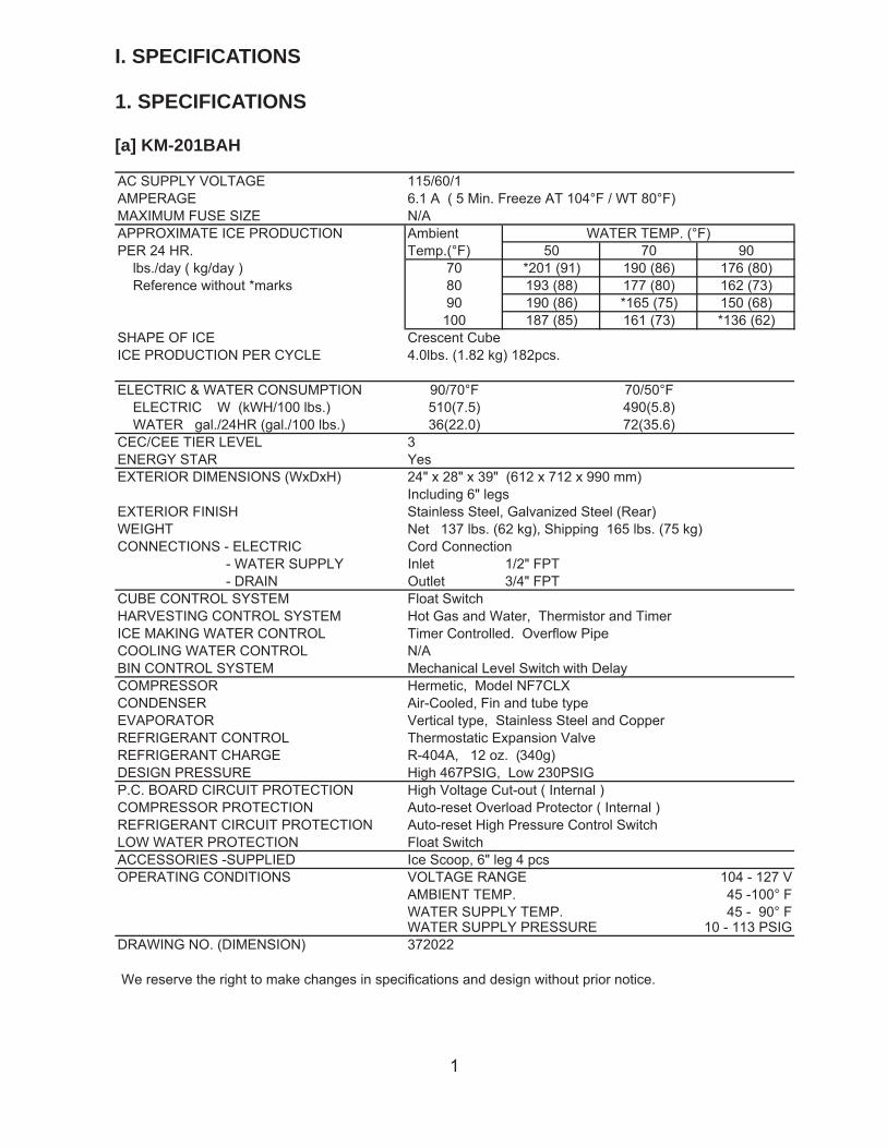
[a] KM-201BAH
AC SUPPLY VOLTAGE 115/60/1AMPERAGE 6.1 A ( 5 Min. Freeze AT 104°F / WT 80°F)MAXIMUM FUSE SIZE N/AAPPROXIMATE ICE PRODUCTION Ambient WATER TEMP. (°F)PER 24 HR. Temp.(°F) 50 70 90 lbs./day ( kg/day ) 70 *201 (91) 190 (86) 176 (80) Reference without *marks 80 193 (88) 177 (80) 162 (73)
90 190 (86) *165 (75) 150 (68)100 187 (85) 161 (73) *136 (62)
SHAPE OF ICEICE PRODUCTION PER CYCLE
Crescent Cube4.0lbs. (1.82 kg) 182pcs.
ELECTRIC & WATER CONSUMPTION 90/70°F 70/50°F ELECTRIC W (kWH/100 lbs.) 510(7.5) 490(5.8) WATER gal./24HR (gal./100 lbs.) 36(22.0) 72(35.6)CEC/CEE TIER LEVEL 3ENERGY STAR YesEXTERIOR DIMENSIONS (WxDxH) 24" x 28" x 39" (612 x 712 x 990 mm)
Including 6" legsEXTERIOR FINISH Stainless Steel, Galvanized Steel (Rear) WEIGHT Net 137 lbs. (62 kg), Shipping 165 lbs. (75 kg)CONNECTIONS - ELECTRIC Cord Connection
- WATER SUPPLY Inlet 1/2" FPT- DRAIN Outlet 3/4" FPT
CUBE CONTROL SYSTEM Float SwitchHARVESTING CONTROL SYSTEM Hot Gas and Water, Thermistor and TimerICE MAKING WATER CONTROL Timer Controlled. Overflow PipeCOOLING WATER CONTROL N/ABIN CONTROL SYSTEM Mechanical Level Switch with DelayCOMPRESSOR Hermetic, Model NF7CLXCONDENSER Air-Cooled, Fin and tube typeEVAPORATOR Vertical type, Stainless Steel and CopperREFRIGERANT CONTROL Thermostatic Expansion ValveREFRIGERANT CHARGE R-404A, 12 oz. (340g)DESIGN PRESSURE High 467PSIG, Low 230PSIGP.C. BOARD CIRCUIT PROTECTION High Voltage Cut-out ( Internal )COMPRESSOR PROTECTION Auto-reset Overload Protector ( Internal )REFRIGERANT CIRCUIT PROTECTION Auto-reset High Pressure Control SwitchLOW WATER PROTECTION Float SwitchACCESSORIES -SUPPLIED Ice Scoop, 6" leg 4 pcsOPERATING CONDITIONS VOLTAGE RANGE 104 - 127 V
AMBIENT TEMP. 45 -100° FWATER SUPPLY TEMP. 45 - 90° FWATER SUPPLY PRESSURE 10 - 113 PSIG
DRAWING NO. (DIMENSION) 372022
We reserve the right to make changes in specifications and design without prior notice.
2
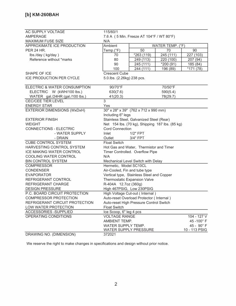
[b] KM-260BAH
AC SUPPLY VOLTAGE 115/60/1AMPERAGE 7.6 A ( 5 Min. Freeze AT 104°F / WT 80°F)MAXIMUM FUSE SIZE N/AAPPROXIMATE ICE PRODUCTION Ambient WATER TEMP. (°F)PER 24 HR. Temp.(°F) 50 70 90 lbs./day ( kg/day ) 70 *263 (119) 245 (111) 227 (103) Reference without *marks 80 249 (113) 220 (100) 207 (94)
90 245 (111) *200 (91) 185 (84)100 244 (111) 196 (89) *171 (78)
SHAPE OF ICEICE PRODUCTION PER CYCLE
Crescent Cube5.0.lbs. (2.26kg) 238 pcs.
ELECTRIC & WATER CONSUMPTION 90/70°F 70/50°F ELECTRIC W (kWH/100 lbs.) 630(7.6) 590(5.4) WATER gal./24HR (gal./100 lbs.) 41(20.3) 78(29.7)CEC/CEE TIER LEVEL 3ENERGY STAR YesEXTERIOR DIMENSIONS (WxDxH) 30" x 28" x 39" (762 x 712 x 990 mm)
Including 6" legsEXTERIOR FINISH Stainless Steel, Galvanized Steel (Rear) WEIGHT Net 154 lbs. (70 kg), Shipping 187 lbs. (85 kg)CONNECTIONS - ELECTRIC Cord Connection
- WATER SUPPLY Inlet 1/2" FPT- DRAIN Outlet 3/4" FPT
CUBE CONTROL SYSTEM Float SwitchHARVESTING CONTROL SYSTEM Hot Gas and Water, Thermistor and TimerICE MAKING WATER CONTROL Timer Controlled. Overflow PipeCOOLING WATER CONTROL N/ABIN CONTROL SYSTEM Mechanical Level Switch with DelayCOMPRESSOR Hermetic, Model SC10CLCONDENSER Air-Cooled, Fin and tube typeEVAPORATOR Vertical type, Stainless Steel and CopperREFRIGERANT CONTROL Thermostatic Expansion ValveREFRIGERANT CHARGE R-404A 12.7oz (360g)DESIGN PRESSURE High 467PSIG, Low 230PSIGP.C. BOARD CIRCUIT PROTECTION High Voltage Cut-out ( Internal )COMPRESSOR PROTECTION Auto-reset Overload Protector ( Internal )REFRIGERANT CIRCUIT PROTECTION Auto-reset High Pressure Control SwitchLOW WATER PROTECTION Float SwitchACCESSORIES -SUPPLIED Ice Scoop, 6" leg 4 pcsOPERATING CONDITIONS VOLTAGE RANGE 104 - 127 V
AMBIENT TEMP. 45 -100° FWATER SUPPLY TEMP. 45 - 90° FWATER SUPPLY PRESSURE 10 - 113 PSIG
DRAWING NO. (DIMENSION) 372021
We reserve the right to make changes in specifications and design without prior notice.
3
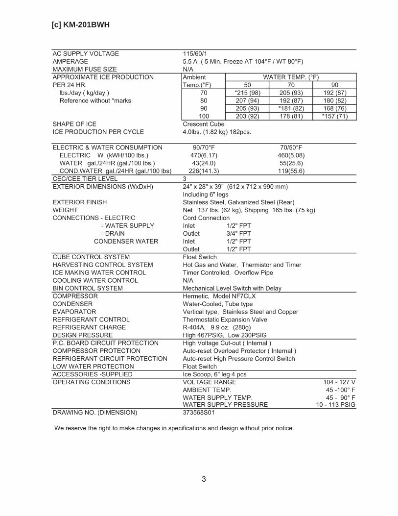
[c] KM-201BWH
AC SUPPLY VOLTAGE 115/60/1AMPERAGE 5.5 A ( 5 Min. Freeze AT 104°F / WT 80°F)MAXIMUM FUSE SIZE N/AAPPROXIMATE ICE PRODUCTION Ambient WATER TEMP. (°F)PER 24 HR. Temp.(°F) 50 70 90 lbs./day ( kg/day ) 70 *215 (98) 205 (93) 192 (87) Reference without *marks 80 207 (94) 192 (87) 180 (82)
90 205 (93) *181 (82) 168 (76)100 203 (92) 178 (81) *157 (71)
SHAPE OF ICEICE PRODUCTION PER CYCLE
Crescent Cube4.0lbs. (1.82 kg) 182pcs.
ELECTRIC & WATER CONSUMPTION 90/70°F 70/50°F ELECTRIC W (kWH/100 lbs.) 470(6.17) 460(5.08) WATER gal./24HR (gal./100 lbs.) 43(24.0) 55(25.6) COND.WATER gal./24HR (gal./100 lbs) 226(141.3) 119(55.6)CEC/CEE TIER LEVEL 3EXTERIOR DIMENSIONS (WxDxH) 24" x 28" x 39" (612 x 712 x 990 mm)
Including 6" legsEXTERIOR FINISH Stainless Steel, Galvanized Steel (Rear) WEIGHT Net 137 lbs. (62 kg), Shipping 165 lbs. (75 kg)CONNECTIONS - ELECTRIC Cord Connection
- WATER SUPPLY Inlet 1/2" FPT- DRAIN Outlet 3/4" FPT
CONDENSER WATER Inlet 1/2" FPTOutlet 1/2" FPT
CUBE CONTROL SYSTEM Float SwitchHARVESTING CONTROL SYSTEM Hot Gas and Water, Thermistor and TimerICE MAKING WATER CONTROL Timer Controlled. Overflow PipeCOOLING WATER CONTROL N/ABIN CONTROL SYSTEM Mechanical Level Switch with DelayCOMPRESSOR Hermetic, Model NF7CLXCONDENSER Water-Cooled, Tube typeEVAPORATOR Vertical type, Stainless Steel and CopperREFRIGERANT CONTROL Thermostatic Expansion ValveREFRIGERANT CHARGE R-404A, 9.9 oz. (280g)DESIGN PRESSURE High 467PSIG, Low 230PSIGP.C. BOARD CIRCUIT PROTECTION High Voltage Cut-out ( Internal )COMPRESSOR PROTECTION Auto-reset Overload Protector ( Internal )REFRIGERANT CIRCUIT PROTECTION Auto-reset High Pressure Control SwitchLOW WATER PROTECTION Float SwitchACCESSORIES -SUPPLIED Ice Scoop, 6" leg 4 pcsOPERATING CONDITIONS VOLTAGE RANGE 104 - 127 V
AMBIENT TEMP. 45 -100° FWATER SUPPLY TEMP. 45 - 90° FWATER SUPPLY PRESSURE 10 - 113 PSIG
DRAWING NO. (DIMENSION) 373568S01
We reserve the right to make changes in specifications and design without prior notice.
4
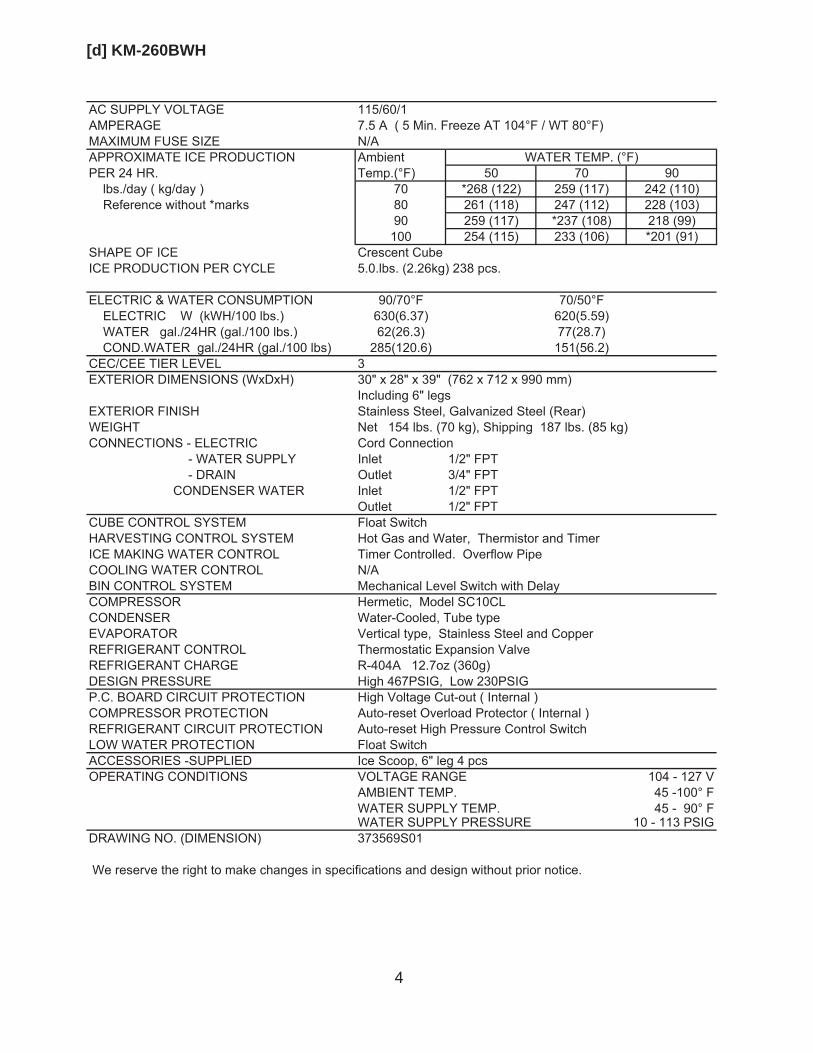
[d] KM-260BWH
AC SUPPLY VOLTAGE 115/60/1AMPERAGE 7.5 A ( 5 Min. Freeze AT 104°F / WT 80°F)MAXIMUM FUSE SIZE N/AAPPROXIMATE ICE PRODUCTION Ambient WATER TEMP. (°F)PER 24 HR. Temp.(°F) 50 70 90 lbs./day ( kg/day ) 70 *268 (122) 259 (117) 242 (110) Reference without *marks 80 261 (118) 247 (112) 228 (103)
90 259 (117) *237 (108) 218 (99)100 254 (115) 233 (106) *201 (91)
SHAPE OF ICEICE PRODUCTION PER CYCLE
Crescent Cube5.0.lbs. (2.26kg) 238 pcs.
ELECTRIC & WATER CONSUMPTION 90/70°F 70/50°F ELECTRIC W (kWH/100 lbs.) 630(6.37) 620(5.59) WATER gal./24HR (gal./100 lbs.) 62(26.3) 77(28.7) COND.WATER gal./24HR (gal./100 lbs) 285(120.6) 151(56.2)CEC/CEE TIER LEVEL 3EXTERIOR DIMENSIONS (WxDxH) 30" x 28" x 39" (762 x 712 x 990 mm)
Including 6" legsEXTERIOR FINISH Stainless Steel, Galvanized Steel (Rear) WEIGHT Net 154 lbs. (70 kg), Shipping 187 lbs. (85 kg)CONNECTIONS - ELECTRIC Cord Connection
- WATER SUPPLY Inlet 1/2" FPT- DRAIN Outlet 3/4" FPT
CONDENSER WATER Inlet 1/2" FPTOutlet 1/2" FPT
CUBE CONTROL SYSTEM Float SwitchHARVESTING CONTROL SYSTEM Hot Gas and Water, Thermistor and TimerICE MAKING WATER CONTROL Timer Controlled. Overflow PipeCOOLING WATER CONTROL N/ABIN CONTROL SYSTEM Mechanical Level Switch with DelayCOMPRESSOR Hermetic, Model SC10CLCONDENSER Water-Cooled, Tube typeEVAPORATOR Vertical type, Stainless Steel and CopperREFRIGERANT CONTROL Thermostatic Expansion ValveREFRIGERANT CHARGE R-404A 12.7oz (360g)DESIGN PRESSURE High 467PSIG, Low 230PSIGP.C. BOARD CIRCUIT PROTECTION High Voltage Cut-out ( Internal )COMPRESSOR PROTECTION Auto-reset Overload Protector ( Internal )REFRIGERANT CIRCUIT PROTECTION Auto-reset High Pressure Control SwitchLOW WATER PROTECTION Float SwitchACCESSORIES -SUPPLIED Ice Scoop, 6" leg 4 pcsOPERATING CONDITIONS VOLTAGE RANGE 104 - 127 V
AMBIENT TEMP. 45 -100° FWATER SUPPLY TEMP. 45 - 90° FWATER SUPPLY PRESSURE 10 - 113 PSIG
DRAWING NO. (DIMENSION) 373569S01
We reserve the right to make changes in specifications and design without prior notice.
5
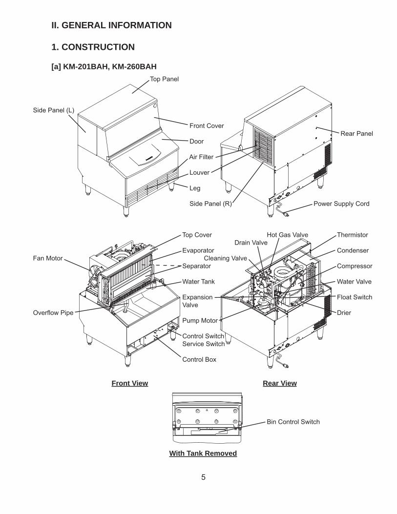
II. GENERAL INFORMATION
1. CONSTRUCTION
[a] KM-201BAH, KM-260BAHTop Panel
Side Panel (L)
Front Cover Rear Panel
Door
Air Filter
Louver
Leg
Side Panel (R) Power Supply Cord
Top Cover Hot Gas Valve Thermistor Drain Valve
Evaporator CondenserFan Motor Cleaning Valve
Separator Compressor
Water Tank Water Valve
Expansion Float Switch Valve
Overfl ow Pipe Drier Pump Motor
Control Switch Service Switch
Control Box
Front View Rear View
Bin Control Switch
With Tank Removed
6
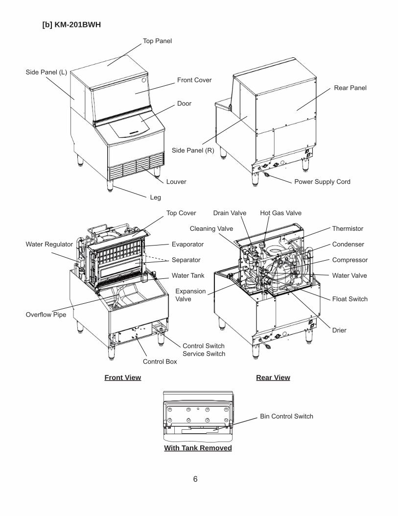
[b] KM-201BWH
Top Panel
Side Panel (L) Front Cover Rear Panel
Door
Side Panel (R)
Louver Power Supply Cord
Leg
Top Cover Drain Valve Hot Gas Valve
Cleaning Valve Thermistor
Water Regulator Evaporator Condenser
Separator Compressor
Water Tank Water Valve
Expansion Valve Float Switch
Overfl ow Pipe
Drier
Control Switch Service Switch Control Box
Front View Rear View
Bin Control Switch
With Tank Removed
7
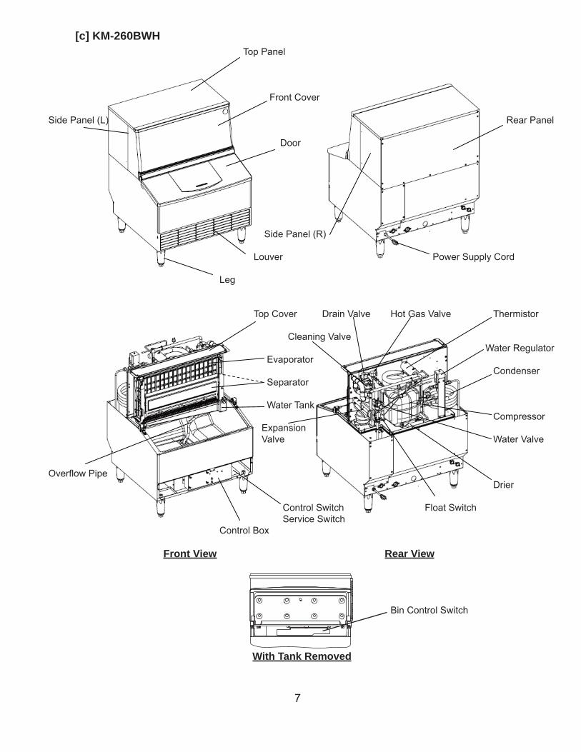
[c] KM-260BWH
Top Panel
Front Cover
Side Panel (L) Rear Panel
Door
Side Panel (R)
Louver Power Supply Cord
Leg
Top Cover Drain Valve Hot Gas Valve Thermistor
Cleaning Valve Water Regulator Evaporator Condenser Separator
Water Tank Compressor Expansion Valve Water Valve
Overfl ow Pipe Drier
Control Switch Float Switch Service Switch Control Box
Front View Rear View
Bin Control Switch
With Tank Removed
8
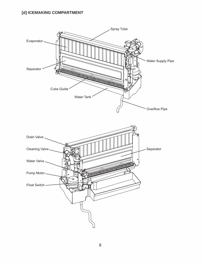
[d] ICEMAKING COMPARTMENT
Spray Tube
Evaporator
Water Supply Pipe
Separator
Cube Guide
Water Tank
Overfl ow Pipe
Drain Valve
Cleaning Valve Separator
Water Valve
Pump Motor
Float Switch
9
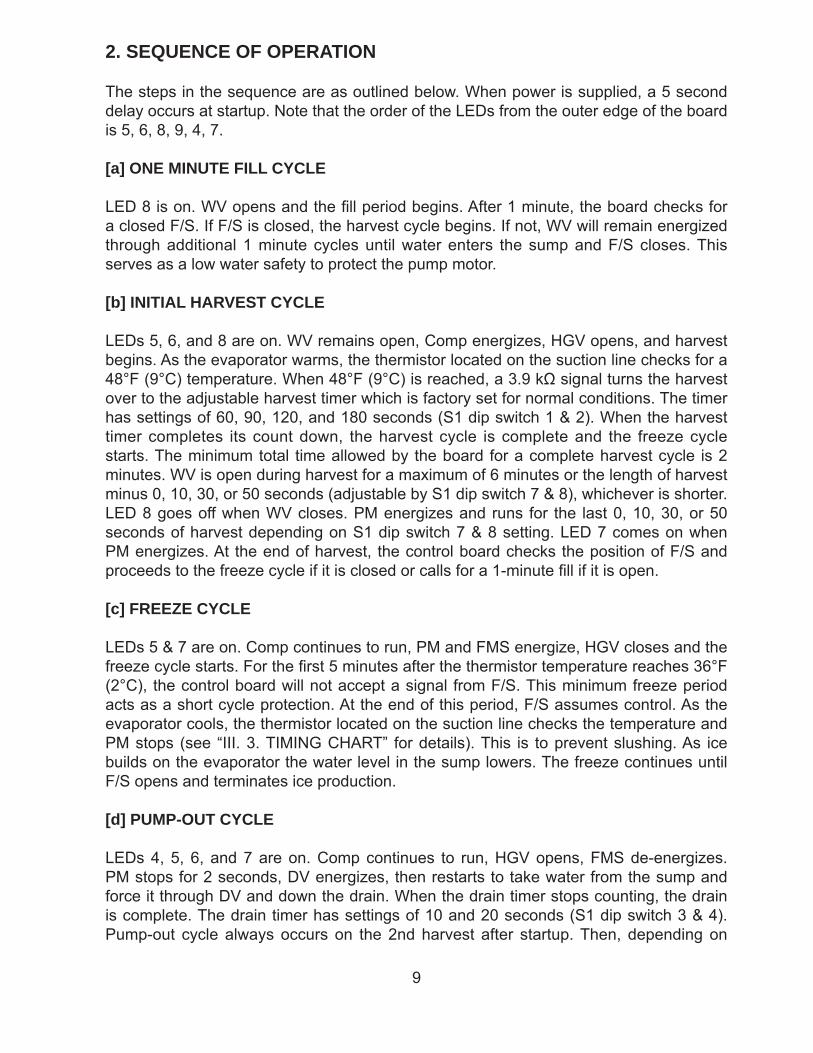
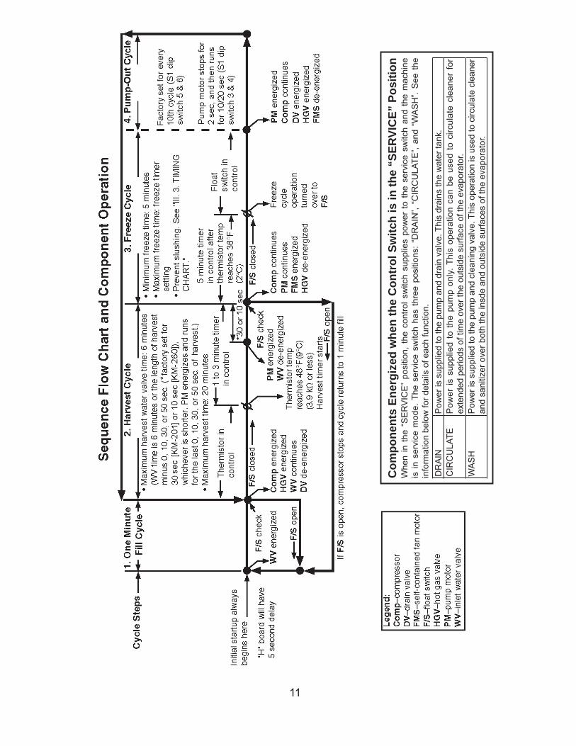
2. SEQUENCE OF OPERATION
The steps in the sequence are as outlined below. When power is supplied, a 5 second delay occurs at startup. Note that the order of the LEDs from the outer edge of the board is 5, 6, 8, 9, 4, 7.
[a] ONE MINUTE FILL CYCLE
LED 8 is on. WV opens and the fi ll period begins. After 1 minute, the board checks for a closed F/S. If F/S is closed, the harvest cycle begins. If not, WV will remain energized through additional 1 minute cycles until water enters the sump and F/S closes. This serves as a low water safety to protect the pump motor.
[b] INITIAL HARVEST CYCLE
LEDs 5, 6, and 8 are on. WV remains open, Comp energizes, HGV opens, and harvest begins. As the evaporator warms, the thermistor located on the suction line checks for a 48°F (9°C) temperature. When 48°F (9°C) is reached, a 3.9 kΩ signal turns the harvest over to the adjustable harvest timer which is factory set for normal conditions. The timer has settings of 60, 90, 120, and 180 seconds (S1 dip switch 1 & 2). When the harvest timer completes its count down, the harvest cycle is complete and the freeze cycle starts. The minimum total time allowed by the board for a complete harvest cycle is 2 minutes. WV is open during harvest for a maximum of 6 minutes or the length of harvest minus 0, 10, 30, or 50 seconds (adjustable by S1 dip switch 7 & 8), whichever is shorter. LED 8 goes off when WV closes. PM energizes and runs for the last 0, 10, 30, or 50 seconds of harvest depending on S1 dip switch 7 & 8 setting. LED 7 comes on when PM energizes. At the end of harvest, the control board checks the position of F/S and proceeds to the freeze cycle if it is closed or calls for a 1-minute fi ll if it is open.
[c] FREEZE CYCLE
LEDs 5 & 7 are on. Comp continues to run, PM and FMS energize, HGV closes and the freeze cycle starts. For the fi rst 5 minutes after the thermistor temperature reaches 36°F (2°C), the control board will not accept a signal from F/S. This minimum freeze period acts as a short cycle protection. At the end of this period, F/S assumes control. As the evaporator cools, the thermistor located on the suction line checks the temperature and PM stops (see “III. 3. TIMING CHART” for details). This is to prevent slushing. As ice builds on the evaporator the water level in the sump lowers. The freeze continues until F/S opens and terminates ice production.
[d] PUMP-OUT CYCLE
LEDs 4, 5, 6, and 7 are on. Comp continues to run, HGV opens, FMS de-energizes. PM stops for 2 seconds, DV energizes, then restarts to take water from the sump and force it through DV and down the drain. When the drain timer stops counting, the drain is complete. The drain timer has settings of 10 and 20 seconds (S1 dip switch 3 & 4). Pump-out cycle always occurs on the 2nd harvest after startup. Then, depending on
10
the control board setting, pump-out cycle occurs every cycle, or every 2nd, 5th, or 10th cycle (S1 dip switch 5 & 6).
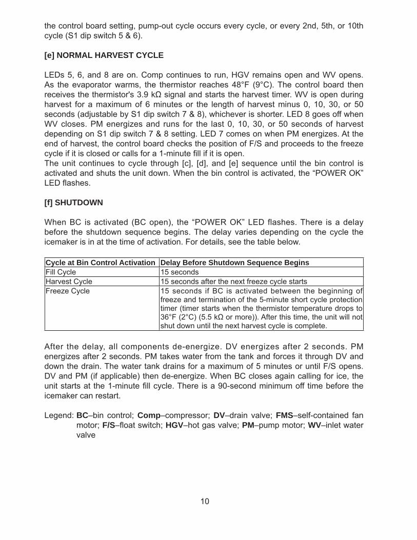
[e] NORMAL HARVEST CYCLE
LEDs 5, 6, and 8 are on. Comp continues to run, HGV remains open and WV opens. As the evaporator warms, the thermistor reaches 48°F (9°C). The control board then receives the thermistor's 3.9 kΩ signal and starts the harvest timer. WV is open during harvest for a maximum of 6 minutes or the length of harvest minus 0, 10, 30, or 50 seconds (adjustable by S1 dip switch 7 & 8), whichever is shorter. LED 8 goes off when WV closes. PM energizes and runs for the last 0, 10, 30, or 50 seconds of harvest depending on S1 dip switch 7 & 8 setting. LED 7 comes on when PM energizes. At the end of harvest, the control board checks the position of F/S and proceeds to the freeze cycle if it is closed or calls for a 1-minute fi ll if it is open.The unit continues to cycle through [c], [d], and [e] sequence until the bin control is activated and shuts the unit down. When the bin control is activated, the “POWER OK” LED fl ashes.
[f] SHUTDOWN
When BC is activated (BC open), the “POWER OK” LED flashes. There is a delay before the shutdown sequence begins. The delay varies depending on the cycle the icemaker is in at the time of activation. For details, see the table below.
Cycle at Bin Control Activation Delay Before Shutdown Sequence BeginsFill Cycle 15 secondsHarvest Cycle 15 seconds after the next freeze cycle startsFreeze Cycle 15 seconds if BC is activated between the beginning of
freeze and termination of the 5-minute short cycle protection timer (timer starts when the thermistor temperature drops to 36°F (2°C) (5.5 kΩ or more)). After this time, the unit will not shut down until the next harvest cycle is complete.
After the delay, all components de-energize. DV energizes after 2 seconds. PM energizes after 2 seconds. PM takes water from the tank and forces it through DV and down the drain. The water tank drains for a maximum of 5 minutes or until F/S opens. DV and PM (if applicable) then de-energize. When BC closes again calling for ice, the unit starts at the 1-minute fi ll cycle. There is a 90-second minimum off time before the icemaker can restart.
Legend: BC–bin control; Comp–compressor; DV–drain valve; FMS–self-contained fan motor; F/S–fl oat switch; HGV–hot gas valve; PM–pump motor; WV–inlet water valve
11
Com
pone
nts
Ener
gize
d w
hen
the
Con
trol
Sw
itch
is in
the
“SER
VIC
E” P
ositi
onW
hen
in t
he “
SE
RV
ICE
” po
sitio
n, t
he c
ontro
l sw
itch
supp
lies
pow
er t
o th
e se
rvic
e sw
itch
and
the
mac
hine
is
in s
ervi
ce m
ode.
The
ser
vice
sw
itch
has
thre
e po
sitio
ns:
“DR
AIN
”, “C
IRC
ULA
TE”,
and
“WA
SH
”. S
ee t
he
info
rmat
ion
belo
w fo
r det
ails
of e
ach
func
tion.
DR
AIN
Pow
er is
sup
plie
d to
the
pum
p an
d dr
ain
valv
e. T
his
drai
ns th
e w
ater
tank
.C
IRC
ULA
TEP
ower
is s
uppl
ied
to t
he p
ump
only
. Thi
s op
erat
ion
can
be u
sed
to c
ircul
ate
clea
ner
for
exte
nded
per
iods
of t
ime
over
the
outs
ide
surfa
ce o
f the
eva
pora
tor.
WA
SH
Pow
er is
sup
plie
d to
the
pum
p an
d cl
eani
ng v
alve
. Thi
s op
erat
ion
is u
sed
to c
ircul
ate
clea
ner
and
sani
tizer
ove
r bot
h th
e in
sde
and
outs
ide
surfa
ces
of th
e ev
apor
ator
.
12
3. CONTROL BOARD
* A HOSHIZAKI exclusive solid-state control is employed in crescent cubers.
* All models are pretested and factory-adjusted.
CAUTION
1. Fragile, handle very carefully.
2. A control board contains integrated circuits, which are susceptible to failure due to static discharge. It is especially important to touch the metal part of the unit before handling or replacing the board.
3. Do not touch the electronic devices on the board or the back of the board to prevent damage to the board.
4. Do not change wiring and connections.
5. Always replace the whole board assembly if it goes bad.
6. Do not short out the power supply to test for voltage.
13
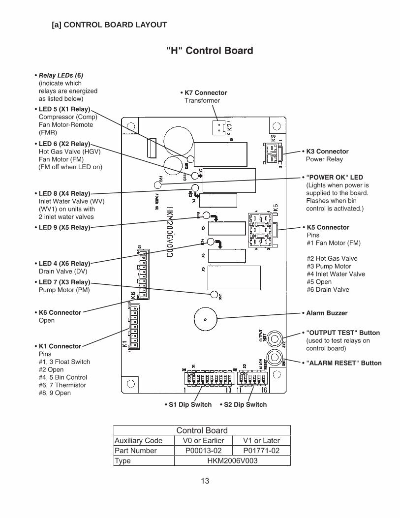
[a] CONTROL BOARD LAYOUT
(FM off when LED on)Power Relay
Control BoardAuxiliary Code V0 or Earlier V1 or LaterPart Number P00013-02 P01771-02Type HKM2006V003
14
[b] FEATURES
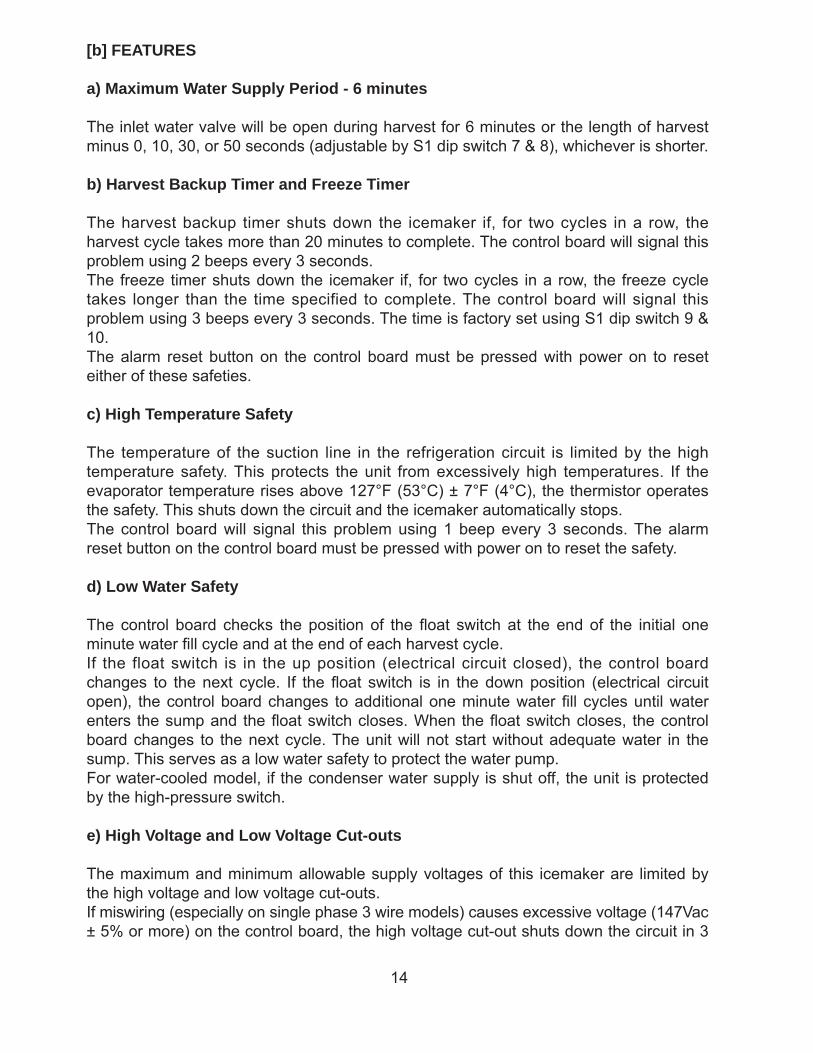
a) Maximum Water Supply Period - 6 minutes
The inlet water valve will be open during harvest for 6 minutes or the length of harvest minus 0, 10, 30, or 50 seconds (adjustable by S1 dip switch 7 & 8), whichever is shorter.
b) Harvest Backup Timer and Freeze Timer
The harvest backup timer shuts down the icemaker if, for two cycles in a row, the harvest cycle takes more than 20 minutes to complete. The control board will signal this problem using 2 beeps every 3 seconds.The freeze timer shuts down the icemaker if, for two cycles in a row, the freeze cycle takes longer than the time specified to complete. The control board will signal this problem using 3 beeps every 3 seconds. The time is factory set using S1 dip switch 9 & 10.The alarm reset button on the control board must be pressed with power on to reset either of these safeties.
c) High Temperature Safety
The temperature of the suction line in the refrigeration circuit is limited by the high temperature safety. This protects the unit from excessively high temperatures. If the evaporator temperature rises above 127°F (53°C) ± 7°F (4°C), the thermistor operates the safety. This shuts down the circuit and the icemaker automatically stops.The control board will signal this problem using 1 beep every 3 seconds. The alarm reset button on the control board must be pressed with power on to reset the safety.
d) Low Water Safety
The control board checks the position of the fl oat switch at the end of the initial one minute water fi ll cycle and at the end of each harvest cycle.If the float switch is in the up position (electrical circuit closed), the control board changes to the next cycle. If the fl oat switch is in the down position (electrical circuit open), the control board changes to additional one minute water fi ll cycles until water enters the sump and the fl oat switch closes. When the fl oat switch closes, the control board changes to the next cycle. The unit will not start without adequate water in the sump. This serves as a low water safety to protect the water pump.For water-cooled model, if the condenser water supply is shut off, the unit is protected by the high-pressure switch.
e) High Voltage and Low Voltage Cut-outs
The maximum and minimum allowable supply voltages of this icemaker are limited by the high voltage and low voltage cut-outs.If miswiring (especially on single phase 3 wire models) causes excessive voltage (147Vac ± 5% or more) on the control board, the high voltage cut-out shuts down the circuit in 3
15
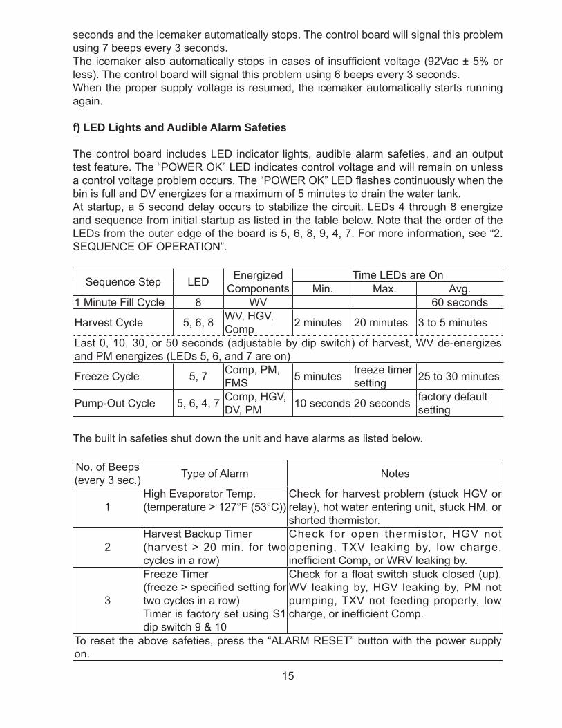
seconds and the icemaker automatically stops. The control board will signal this problem using 7 beeps every 3 seconds.The icemaker also automatically stops in cases of insuffi cient voltage (92Vac ± 5% or less). The control board will signal this problem using 6 beeps every 3 seconds.When the proper supply voltage is resumed, the icemaker automatically starts running again.
f) LED Lights and Audible Alarm Safeties
The control board includes LED indicator lights, audible alarm safeties, and an output test feature. The “POWER OK” LED indicates control voltage and will remain on unless a control voltage problem occurs. The “POWER OK” LED fl ashes continuously when the bin is full and DV energizes for a maximum of 5 minutes to drain the water tank.At startup, a 5 second delay occurs to stabilize the circuit. LEDs 4 through 8 energize and sequence from initial startup as listed in the table below. Note that the order of the LEDs from the outer edge of the board is 5, 6, 8, 9, 4, 7. For more information, see “2. SEQUENCE OF OPERATION”.
Sequence Step LED Energized Components
Time LEDs are OnMin. Max. Avg.
1 Minute Fill Cycle 8 WV 60 seconds
Harvest Cycle 5, 6, 8 WV, HGV, Comp 2 minutes 20 minutes 3 to 5 minutes
Last 0, 10, 30, or 50 seconds (adjustable by dip switch) of harvest, WV de-energizes and PM energizes (LEDs 5, 6, and 7 are on)
Freeze Cycle 5, 7 Comp, PM, FMS 5 minutes freeze timer
setting 25 to 30 minutes
Pump-Out Cycle 5, 6, 4, 7 Comp, HGV, DV, PM 10 seconds 20 seconds factory default
setting
The built in safeties shut down the unit and have alarms as listed below.
No. of Beeps (every 3 sec.) Type of Alarm Notes
1High Evaporator Temp.(temperature > 127°F (53°C))
Check for harvest problem (stuck HGV or relay), hot water entering unit, stuck HM, or shorted thermistor.
2Harvest Backup Timer(harvest > 20 min. for two cycles in a row)
Check for open thermistor, HGV not opening, TXV leaking by, low charge, ineffi cient Comp, or WRV leaking by.
3
Freeze Timer(freeze > specifi ed setting for two cycles in a row)Timer is factory set using S1 dip switch 9 & 10
Check for a fl oat switch stuck closed (up), WV leaking by, HGV leaking by, PM not pumping, TXV not feeding properly, low charge, or ineffi cient Comp.
To reset the above safeties, press the “ALARM RESET” button with the power supply on.
16
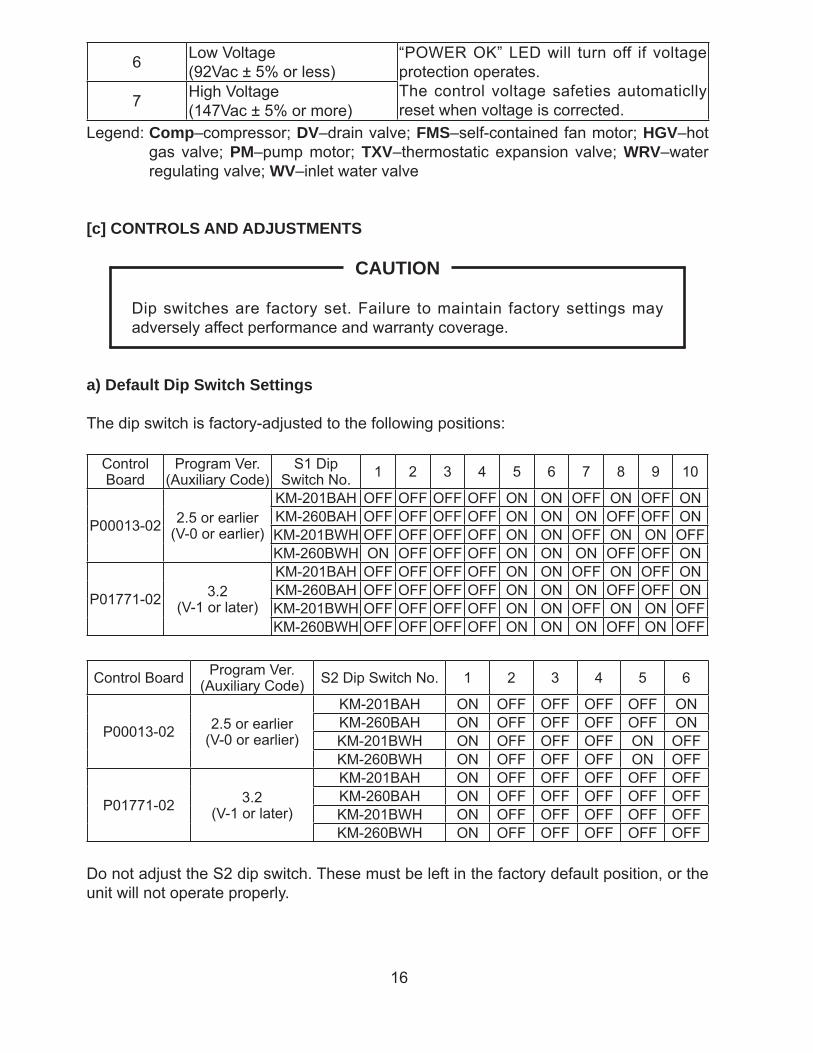
6 Low Voltage(92Vac ± 5% or less)
“POWER OK” LED will turn off if voltage protection operates.The control voltage safeties automaticlly reset when voltage is corrected.7 High Voltage
(147Vac ± 5% or more)Legend: Comp–compressor; DV–drain valve; FMS–self-contained fan motor; HGV–hot
gas valve; PM–pump motor; TXV–thermostatic expansion valve; WRV–water regulating valve; WV–inlet water valve
[c] CONTROLS AND ADJUSTMENTS
CAUTION
Dip switches are factory set. Failure to maintain factory settings may adversely affect performance and warranty coverage.
a) Default Dip Switch Settings
The dip switch is factory-adjusted to the following positions:
Control Board
Program Ver.(Auxiliary Code)
S1 Dip Switch No. 1 2 3 4 5 6 7 8 9 10
P00013-02 2.5 or earlier(V-0 or earlier)
KM-201BAH OFF OFF OFF OFF ON ON OFF ON OFF ONKM-260BAH OFF OFF OFF OFF ON ON ON OFF OFF ONKM-201BWH OFF OFF OFF OFF ON ON OFF ON ON OFFKM-260BWH ON OFF OFF OFF ON ON ON OFF OFF ON
P01771-02 3.2(V-1 or later)
KM-201BAH OFF OFF OFF OFF ON ON OFF ON OFF ONKM-260BAH OFF OFF OFF OFF ON ON ON OFF OFF ONKM-201BWH OFF OFF OFF OFF ON ON OFF ON ON OFFKM-260BWH OFF OFF OFF OFF ON ON ON OFF ON OFF
Control Board Program Ver.(Auxiliary Code) S2 Dip Switch No. 1 2 3 4 5 6
P00013-02 2.5 or earlier(V-0 or earlier)
KM-201BAH ON OFF OFF OFF OFF ONKM-260BAH ON OFF OFF OFF OFF ONKM-201BWH ON OFF OFF OFF ON OFFKM-260BWH ON OFF OFF OFF ON OFF
P01771-02 3.2(V-1 or later)
KM-201BAH ON OFF OFF OFF OFF OFFKM-260BAH ON OFF OFF OFF OFF OFFKM-201BWH ON OFF OFF OFF OFF OFFKM-260BWH ON OFF OFF OFF OFF OFF
Do not adjust the S2 dip switch. These must be left in the factory default position, or the unit will not operate properly.
17
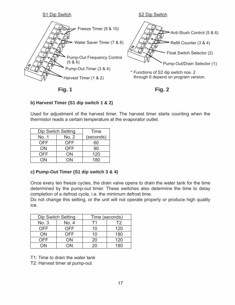
Fig. 1 Fig. 2
Freeze Timer (9 & 10)
Water Saver Timer (7 & 8)
Pump-Out Frequency Control (5 & 6)
Pump-Out Timer (3 & 4)
Harvest Timer (1 & 2)
S1 Dip Switch S2 Dip Switch
Anti-Slush Control (5 & 6)
Float Switch Selector (2)
Pump-Out/Drain Selector (1)
b) Harvest Timer (S1 dip switch 1 & 2)
Used for adjustment of the harvest timer. The harvest timer starts counting when the thermistor reads a certain temperature at the evaporator outlet.
Dip Switch Setting Time(seconds)No. 1 No. 2
OFF OFF 60ON OFF 90OFF ON 120ON ON 180
c) Pump-Out Timer (S1 dip switch 3 & 4)
Once every ten freeze cycles, the drain valve opens to drain the water tank for the time determined by the pump-out timer. These switches also determine the time to delay completion of a defrost cycle, i.e. the minimum defrost time.Do not change this setting, or the unit will not operate properly or produce high quality ice.
Dip Switch Setting Time (seconds)No. 3 No. 4 T1 T2OFF OFF 10 120ON OFF 10 180OFF ON 20 120ON ON 20 180
T1: Time to drain the water tankT2: Harvest timer at pump-out
Refi ll Counter (3 & 4)
* Functions of S2 dip switch nos. 2 through 6 depend on program version.
18
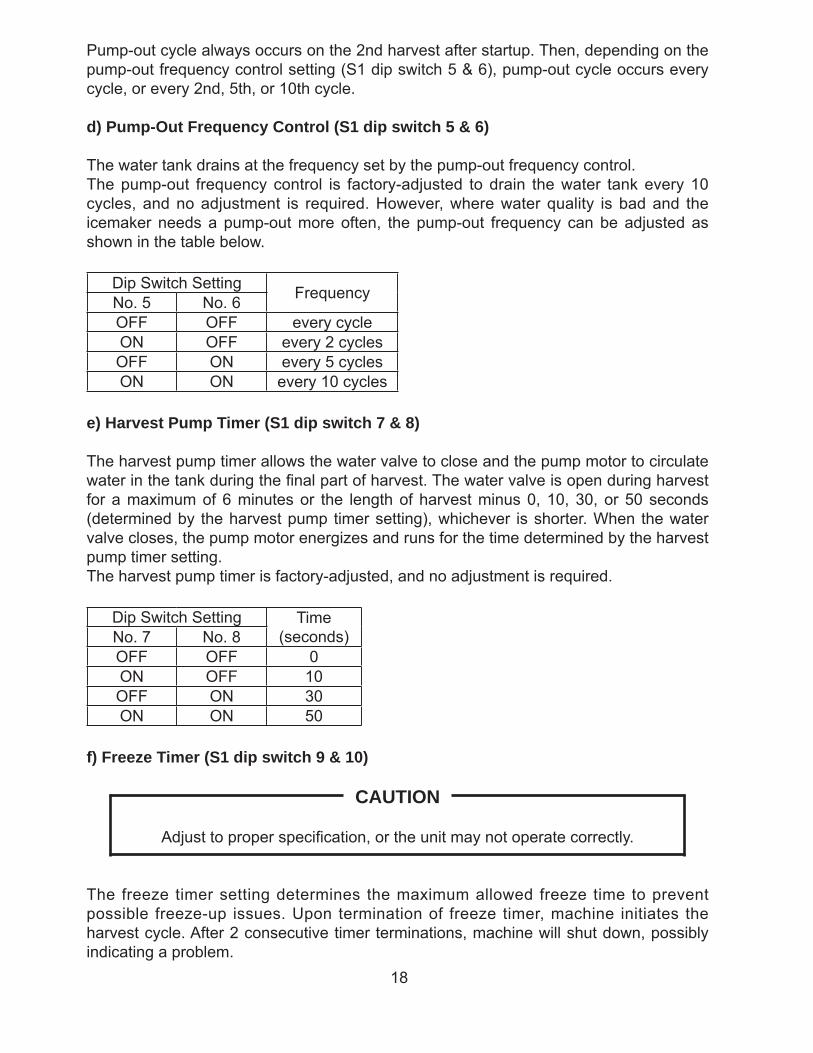
Pump-out cycle always occurs on the 2nd harvest after startup. Then, depending on the pump-out frequency control setting (S1 dip switch 5 & 6), pump-out cycle occurs every cycle, or every 2nd, 5th, or 10th cycle.
d) Pump-Out Frequency Control (S1 dip switch 5 & 6)
The water tank drains at the frequency set by the pump-out frequency control.The pump-out frequency control is factory-adjusted to drain the water tank every 10 cycles, and no adjustment is required. However, where water quality is bad and the icemaker needs a pump-out more often, the pump-out frequency can be adjusted as shown in the table below.
Dip Switch Setting FrequencyNo. 5 No. 6OFF OFF every cycleON OFF every 2 cyclesOFF ON every 5 cyclesON ON every 10 cycles
e) Harvest Pump Timer (S1 dip switch 7 & 8)
The harvest pump timer allows the water valve to close and the pump motor to circulate water in the tank during the fi nal part of harvest. The water valve is open during harvest for a maximum of 6 minutes or the length of harvest minus 0, 10, 30, or 50 seconds (determined by the harvest pump timer setting), whichever is shorter. When the water valve closes, the pump motor energizes and runs for the time determined by the harvest pump timer setting.The harvest pump timer is factory-adjusted, and no adjustment is required.
Dip Switch Setting Time(seconds)No. 7 No. 8
OFF OFF 0ON OFF 10OFF ON 30ON ON 50
f) Freeze Timer (S1 dip switch 9 & 10)
CAUTION
Adjust to proper specifi cation, or the unit may not operate correctly.
The freeze timer setting determines the maximum allowed freeze time to prevent possible freeze-up issues. Upon termination of freeze timer, machine initiates the harvest cycle. After 2 consecutive timer terminations, machine will shut down, possibly indicating a problem.
19
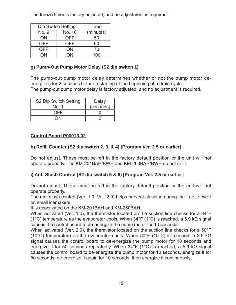
The freeze timer is factory adjusted, and no adjustment is required.
Dip Switch Setting Time(minutes)No. 9 No. 10
ON OFF 50OFF OFF 60OFF ON 70ON ON 100
g) Pump-Out Pump Motor Delay (S2 dip switch 1)
The pump-out pump motor delay determines whether or not the pump motor de-energizes for 2 seconds before restarting at the beginning of a drain cycle.The pump-out pump motor delay is factory adjusted, and no adjustment is required.
S2 Dip Switch Setting Delay(seconds)No. 1
OFF 0ON 2
Control Board P00013-02
h) Refi ll Counter (S2 dip switch 2, 3, & 4) [Program Ver. 2.5 or earlier]
Do not adjust. These must be left in the factory default position or the unit will not operate properly. The KM-201BAH/BWH and KM-260BAH/BWH do not refi ll.
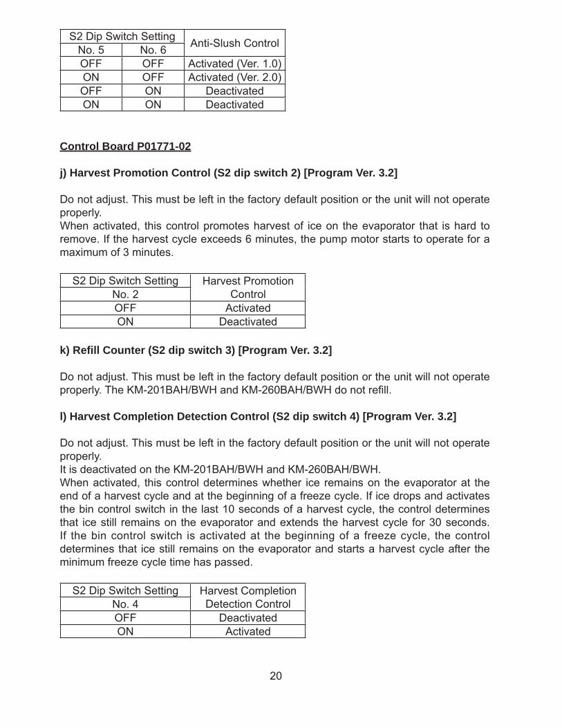
i) Anti-Slush Control (S2 dip switch 5 & 6) [Program Ver. 2.5 or earlier]
Do not adjust. These must be left in the factory default position or the unit will not operate properly.The anti-slush control (Ver. 1.0, Ver. 2.0) helps prevent slushing during the freeze cycle on small icemakers.It is deactivated on the KM-201BAH and KM-260BAH.When activated (Ver. 1.0), the thermistor located on the suction line checks for a 34°F (1°C) temperature as the evaporator cools. When 34°F (1°C) is reached, a 5.9 kΩ signal causes the control board to de-energize the pump motor for 10 seconds.When activated (Ver. 2.0), the thermistor located on the suction line checks for a 50°F (10°C) temperature as the evaporator cools. When 50°F (10°C) is reached, a 3.9 kΩ signal causes the control board to de-energize the pump motor for 10 seconds and energize it for 50 seconds repeatedly. When 34°F (1°C) is reached, a 5.9 kΩ signal causes the control board to de-energize the pump motor for 10 seconds, energize it for 50 seconds, de-energize it again for 10 seconds, then energize it continuously.
20
S2 Dip Switch Setting Anti-Slush ControlNo. 5 No. 6OFF OFF Activated (Ver. 1.0)ON OFF Activated (Ver. 2.0)OFF ON DeactivatedON ON Deactivated
Control Board P01771-02
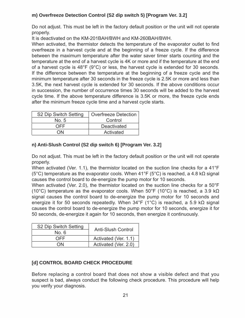
j) Harvest Promotion Control (S2 dip switch 2) [Program Ver. 3.2]
Do not adjust. This must be left in the factory default position or the unit will not operate properly.When activated, this control promotes harvest of ice on the evaporator that is hard to remove. If the harvest cycle exceeds 6 minutes, the pump motor starts to operate for a maximum of 3 minutes.
S2 Dip Switch Setting Harvest Promotion ControlNo. 2
OFF ActivatedON Deactivated
k) Refi ll Counter (S2 dip switch 3) [Program Ver. 3.2]
Do not adjust. This must be left in the factory default position or the unit will not operate properly. The KM-201BAH/BWH and KM-260BAH/BWH do not refi ll.
l) Harvest Completion Detection Control (S2 dip switch 4) [Program Ver. 3.2]
Do not adjust. This must be left in the factory default position or the unit will not operate properly.It is deactivated on the KM-201BAH/BWH and KM-260BAH/BWH.When activated, this control determines whether ice remains on the evaporator at the end of a harvest cycle and at the beginning of a freeze cycle. If ice drops and activates the bin control switch in the last 10 seconds of a harvest cycle, the control determines that ice still remains on the evaporator and extends the harvest cycle for 30 seconds. If the bin control switch is activated at the beginning of a freeze cycle, the control determines that ice still remains on the evaporator and starts a harvest cycle after the minimum freeze cycle time has passed.
S2 Dip Switch Setting Harvest Completion Detection ControlNo. 4
OFF DeactivatedON Activated
21
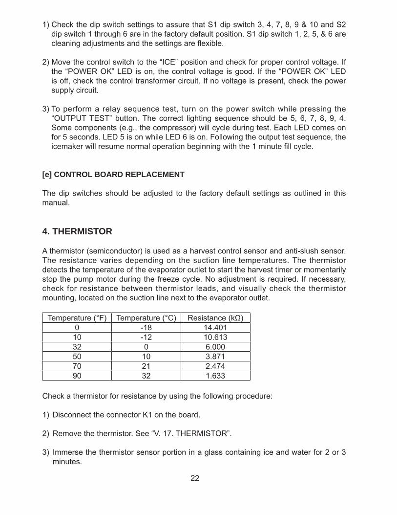
m) Overfreeze Detection Control (S2 dip switch 5) [Program Ver. 3.2]
Do not adjust. This must be left in the factory default position or the unit will not operate properly.It is deactivated on the KM-201BAH/BWH and KM-260BAH/BWH.When activated, the thermistor detects the temperature of the evaporator outlet to fi nd overfreeze in a harvest cycle and at the beginning of a freeze cycle. If the difference between the maximum temperature after the water saver timer starts counting and the temperature at the end of a harvest cycle is 4K or more and if the temperature at the end of a harvest cycle is 48°F (9°C) or less, the harvest cycle is extended for 30 seconds. If the difference between the temperature at the beginning of a freeze cycle and the minimum temperature after 30 seconds in the freeze cycle is 2.5K or more and less than 3.5K, the next harvest cycle is extended for 30 seconds. If the above conditions occur in succession, the number of occurrence times 30 seconds will be added to the harvest cycle time. If the above temperature difference is 3.5K or more, the freeze cycle ends after the minimum freeze cycle time and a harvest cycle starts.
S2 Dip Switch Setting Overfreeze Detection ControlNo. 5
OFF DeactivatedON Activated
n) Anti-Slush Control (S2 dip switch 6) [Program Ver. 3.2]
Do not adjust. This must be left in the factory default position or the unit will not operate properly.When activated (Ver. 1.1), the thermistor located on the suction line checks for a 41°F (5°C) temperature as the evaporator cools. When 41°F (5°C) is reached, a 4.8 kΩ signal causes the control board to de-energize the pump motor for 10 seconds.When activated (Ver. 2.0), the thermistor located on the suction line checks for a 50°F (10°C) temperature as the evaporator cools. When 50°F (10°C) is reached, a 3.9 kΩ signal causes the control board to de-energize the pump motor for 10 seconds and energize it for 50 seconds repeatedly. When 34°F (1°C) is reached, a 5.9 kΩ signal causes the control board to de-energize the pump motor for 10 seconds, energize it for 50 seconds, de-energize it again for 10 seconds, then energize it continuously.
S2 Dip Switch Setting Anti-Slush ControlNo. 6OFF Activated (Ver. 1.1)ON Activated (Ver. 2.0)
[d] CONTROL BOARD CHECK PROCEDURE
Before replacing a control board that does not show a visible defect and that you suspect is bad, always conduct the following check procedure. This procedure will help you verify your diagnosis.
22
1) Check the dip switch settings to assure that S1 dip switch 3, 4, 7, 8, 9 & 10 and S2 dip switch 1 through 6 are in the factory default position. S1 dip switch 1, 2, 5, & 6 are cleaning adjustments and the settings are fl exible.
2) Move the control switch to the “ICE” position and check for proper control voltage. If the “POWER OK” LED is on, the control voltage is good. If the “POWER OK” LED is off, check the control transformer circuit. If no voltage is present, check the power supply circuit.
3) To perform a relay sequence test, turn on the power switch while pressing the “OUTPUT TEST” button. The correct lighting sequence should be 5, 6, 7, 8, 9, 4. Some components (e.g., the compressor) will cycle during test. Each LED comes on for 5 seconds. LED 5 is on while LED 6 is on. Following the output test sequence, the icemaker will resume normal operation beginning with the 1 minute fi ll cycle.
[e] CONTROL BOARD REPLACEMENT
The dip switches should be adjusted to the factory default settings as outlined in this manual.
4. THERMISTOR
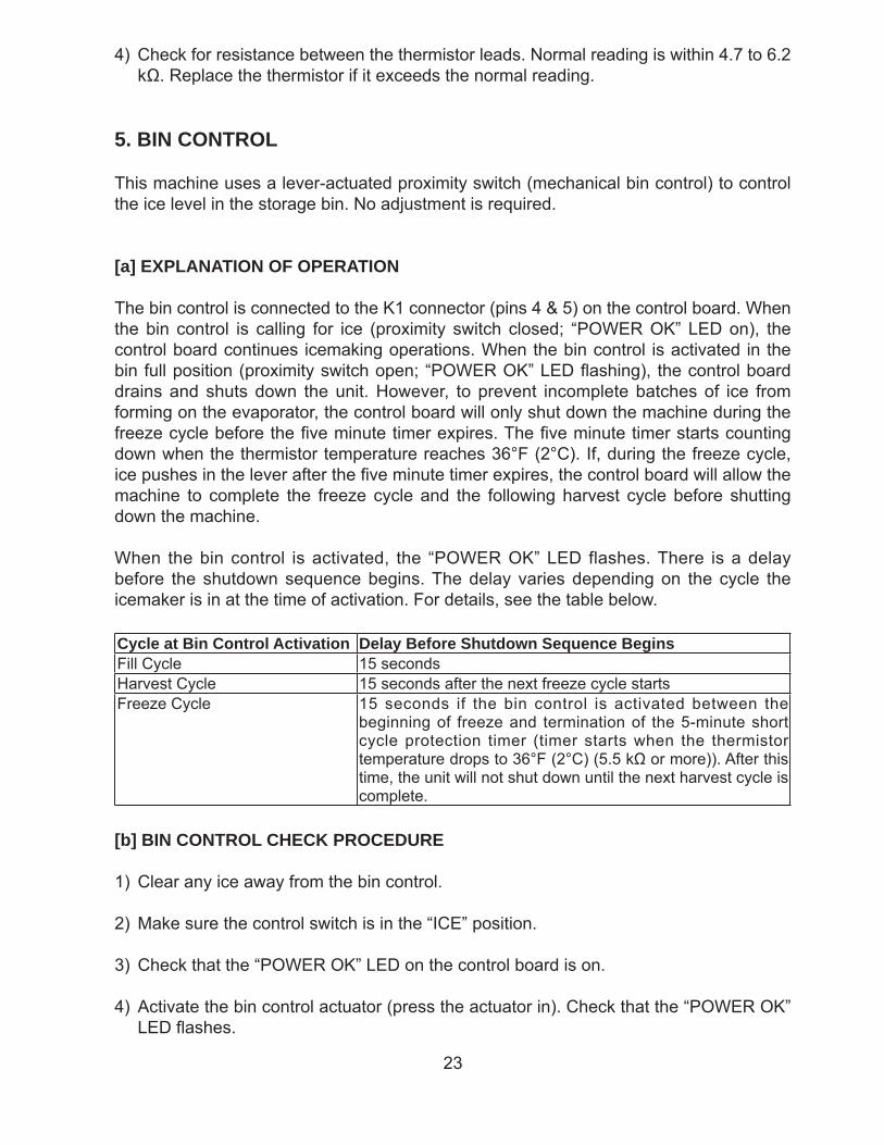
A thermistor (semiconductor) is used as a harvest control sensor and anti-slush sensor. The resistance varies depending on the suction line temperatures. The thermistor detects the temperature of the evaporator outlet to start the harvest timer or momentarily stop the pump motor during the freeze cycle. No adjustment is required. If necessary, check for resistance between thermistor leads, and visually check the thermistor mounting, located on the suction line next to the evaporator outlet.
Temperature (°F) Temperature (°C) Resistance (kΩ)0 -18 14.401
10 -12 10.61332 0 6.00050 10 3.87170 21 2.47490 32 1.633
Check a thermistor for resistance by using the following procedure:
1) Disconnect the connector K1 on the board.
2) Remove the thermistor. See “V. 17. THERMISTOR”.
3) Immerse the thermistor sensor portion in a glass containing ice and water for 2 or 3 minutes.
23
4) Check for resistance between the thermistor leads. Normal reading is within 4.7 to 6.2 kΩ. Replace the thermistor if it exceeds the normal reading.
5. BIN CONTROL
This machine uses a lever-actuated proximity switch (mechanical bin control) to control the ice level in the storage bin. No adjustment is required.
[a] EXPLANATION OF OPERATION
The bin control is connected to the K1 connector (pins 4 & 5) on the control board. When the bin control is calling for ice (proximity switch closed; “POWER OK” LED on), the control board continues icemaking operations. When the bin control is activated in the bin full position (proximity switch open; “POWER OK” LED fl ashing), the control board drains and shuts down the unit. However, to prevent incomplete batches of ice from forming on the evaporator, the control board will only shut down the machine during the freeze cycle before the fi ve minute timer expires. The fi ve minute timer starts counting down when the thermistor temperature reaches 36°F (2°C). If, during the freeze cycle, ice pushes in the lever after the fi ve minute timer expires, the control board will allow the machine to complete the freeze cycle and the following harvest cycle before shutting down the machine.
When the bin control is activated, the “POWER OK” LED flashes. There is a delay before the shutdown sequence begins. The delay varies depending on the cycle the icemaker is in at the time of activation. For details, see the table below.
Cycle at Bin Control Activation Delay Before Shutdown Sequence BeginsFill Cycle 15 secondsHarvest Cycle 15 seconds after the next freeze cycle startsFreeze Cycle 15 seconds if the bin control is activated between the
beginning of freeze and termination of the 5-minute short cycle protection timer (timer starts when the thermistor temperature drops to 36°F (2°C) (5.5 kΩ or more)). After this time, the unit will not shut down until the next harvest cycle is complete.
[b] BIN CONTROL CHECK PROCEDURE
1) Clear any ice away from the bin control.
2) Make sure the control switch is in the “ICE” position.
3) Check that the “POWER OK” LED on the control board is on.
4) Activate the bin control actuator (press the actuator in). Check that the “POWER OK” LED fl ashes.
24
5) Disconnect the bin control at the 2-pin connector attached to the black wires coming from the K1 connector (pins 4 & 5) on the control board.
6) Check for continuity across the bin control leads. When calling for ice, the bin control proximity switch should be closed. If open, replace the bin control. Activate the bin control actuator (press the actuator in), check for continuity across the bin control leads. The bin control proximity switch should be open. If closed, replace the bin control.
7) Reconnect the 2-pin connector. Allow the machine to cycle into the freeze cycle. In the fi rst 5 minutes of the freeze cycle, activate the bin control actuator (press the actuator in). The “POWER OK” LED should fl ash and the machine should turn off. If not, replace the control board.
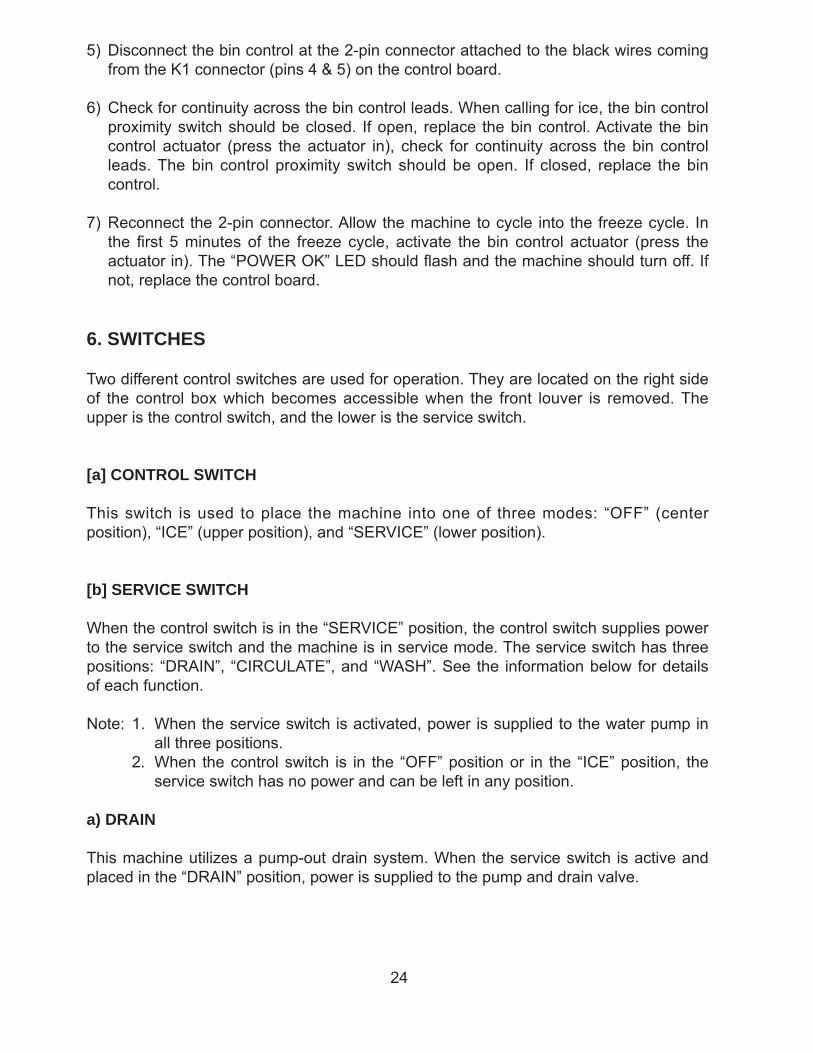
6. SWITCHES
Two different control switches are used for operation. They are located on the right side of the control box which becomes accessible when the front louver is removed. The upper is the control switch, and the lower is the service switch.
[a] CONTROL SWITCH
This switch is used to place the machine into one of three modes: “OFF” (center position), “ICE” (upper position), and “SERVICE” (lower position).
[b] SERVICE SWITCH
When the control switch is in the “SERVICE” position, the control switch supplies power to the service switch and the machine is in service mode. The service switch has three positions: “DRAIN”, “CIRCULATE”, and “WASH”. See the information below for details of each function.
Note: 1. When the service switch is activated, power is supplied to the water pump in all three positions.
2. When the control switch is in the “OFF” position or in the “ICE” position, the service switch has no power and can be left in any position.
a) DRAIN
This machine utilizes a pump-out drain system. When the service switch is active and placed in the “DRAIN” position, power is supplied to the pump and drain valve.
25
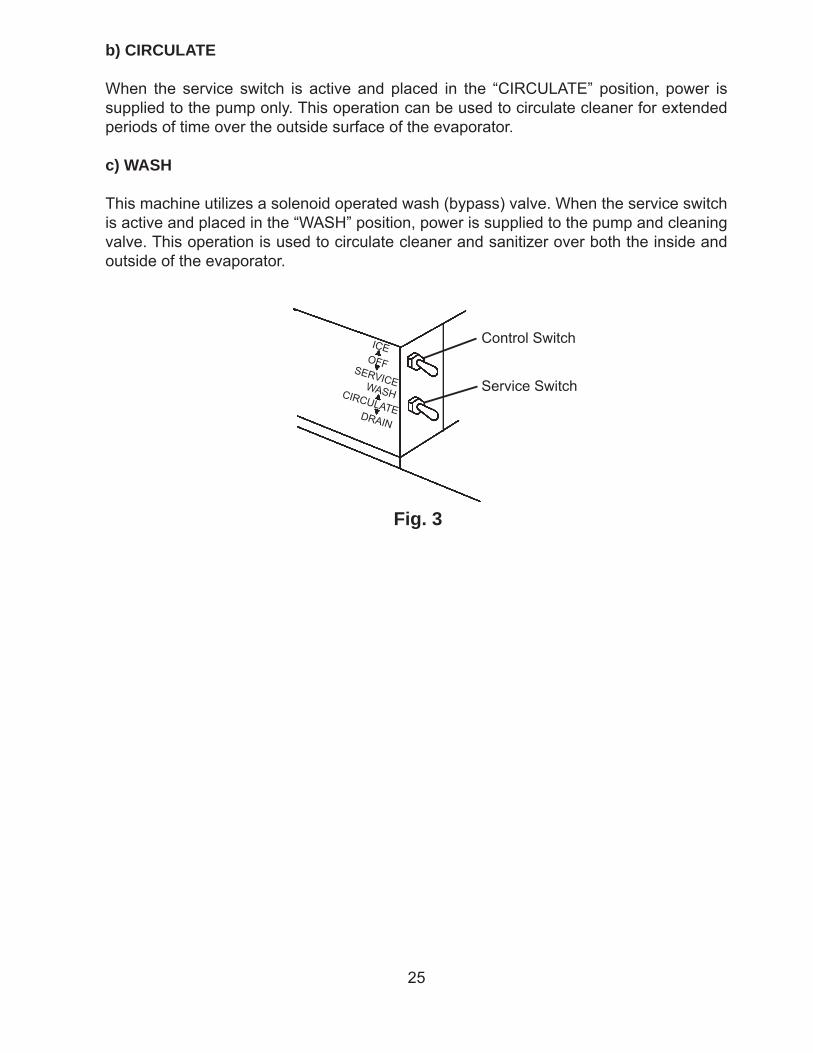
b) CIRCULATE
When the service switch is active and placed in the “CIRCULATE” position, power is supplied to the pump only. This operation can be used to circulate cleaner for extended periods of time over the outside surface of the evaporator.
c) WASH
This machine utilizes a solenoid operated wash (bypass) valve. When the service switch is active and placed in the “WASH” position, power is supplied to the pump and cleaning valve. This operation is used to circulate cleaner and sanitizer over both the inside and outside of the evaporator.
Fig. 3
Control Switch
Service SwitchSERVICE
ICEOFF
DRAIN
WASHCIRCULATE
26
Eva
pora
tor
Floa
tS
witc
h
Cub
e G
uide
Drie
r
Ther
mis
tor
Suc
tion
Line
Wat
erS
uppl
y
Wat
er V
alve
Spr
ay T
ube
Fan
Con
dens
er Exp
ansi
on V
alve
Com
pres
sor
Acc
ess
Val
ve
Stra
iner
Hot
Gas
Val
ve
Hig
h P
ress
ure
Sw
itch
Ref
riger
ant C
ircui
t
Wat
er C
ircui
t
Dis
char
ge L
ine
Insu
latio
n Tu
be
Pum
pM
otor
Wat
er T
ank
Dra
in
Dra
inV
alve
Cle
anin
gV
alve
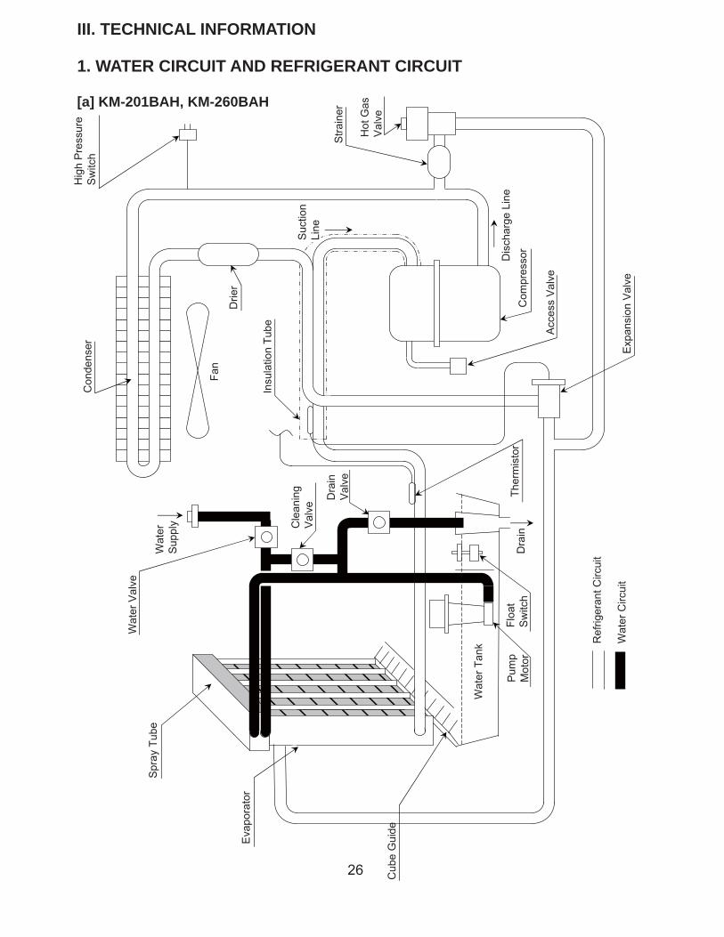
III. TECHNICAL INFORMATION
1. WATER CIRCUIT AND REFRIGERANT CIRCUIT
[a] KM-201BAH, KM-260BAH
27
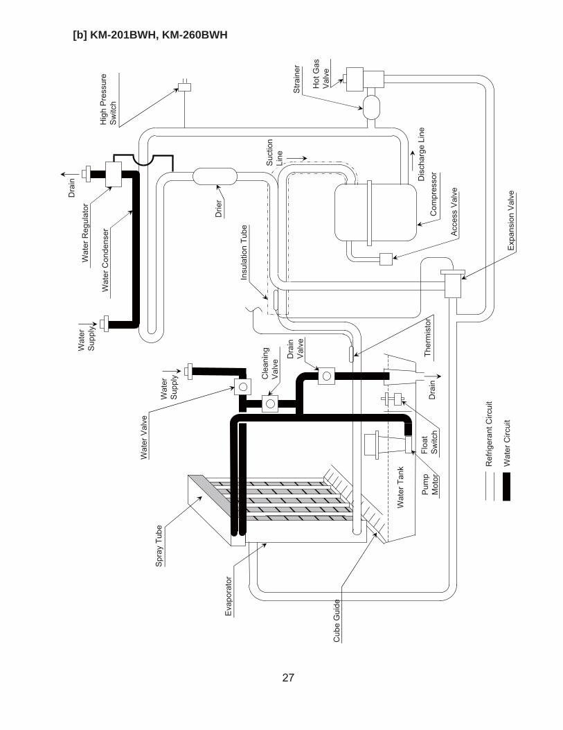
[b] KM-201BWH, KM-260BWH
Eva
pora
tor
Floa
tS
witc
h
Dra
in
Cub
e G
uide
Drie
r
Cle
anin
gV
alve
Ther
mis
tor
Suc
tion
Line
Wat
erS
uppl
y
Wat
er V
alve
Spr
ay T
ube
Wat
er C
onde
nser
Exp
ansi
on V
alve
Com
pres
sor
Acc
ess
Val
ve
Stra
iner
Hot
Gas
Val
ve
Hig
h P
ress
ure
Sw
itch
Ref
riger
ant C
ircui
t
Wat
er C
ircui
t
Dis
char
ge L
ine
Insu
latio
n Tu
be
Pum
pM
otor
Wat
er T
ank
Dra
in
Dra
inV
alveWat
erS
uppl
yW
ater
Reg
ulat
or
28
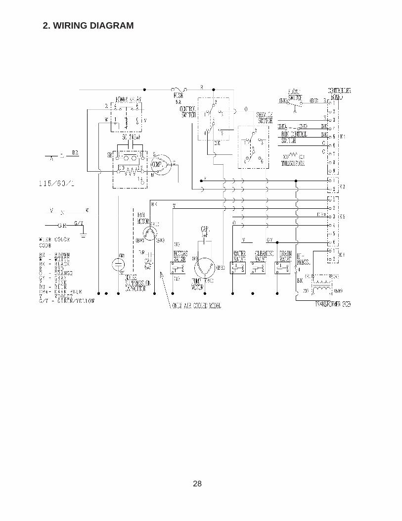
2. WIRING DIAGRAM
29
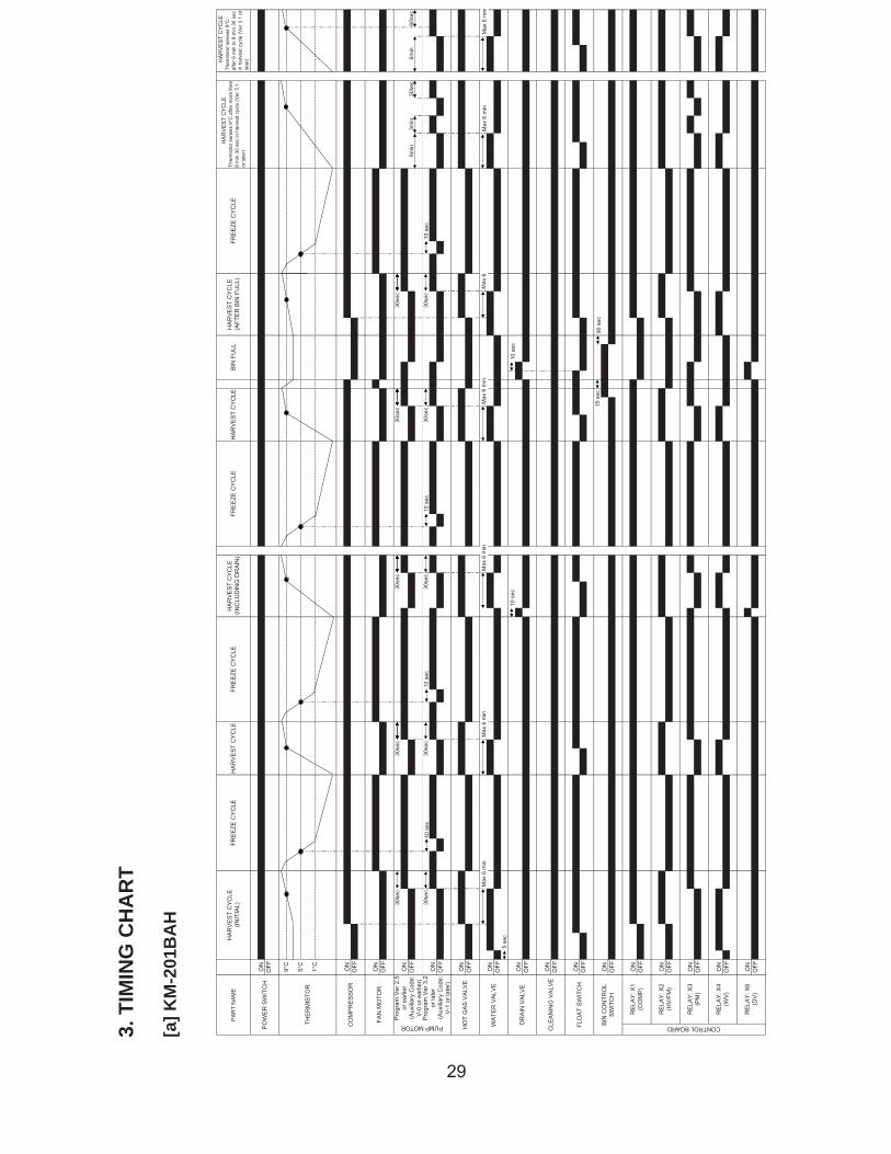
3. T
IMIN
G C
HA
RT
[a] K
M-2
01B
AH
30se
c30
sec
30se
c30
sec
30se
c
30se
c30
sec
30se
c30
sec
30se
c
H
AR
VE
ST
CY
CLE
Ther
mis
tor s
ense
s 9°
Caf
ter 6
min
to 8
min
30
sec
in h
arve
st c
ycle
(Ver
3.1
or
late
r) 6min
60se
c
H
AR
VE
ST
CY
CLE
Ther
mis
tor s
ense
s 9°
C a
fter m
ore
than
8 m
in 3
0 se
c in
har
vest
cyc
le (V
er 3
.1or
late
r)
HA
RV
ES
T C
YC
LE(A
FTE
R B
IN F
ULL
)FR
EE
ZE C
YC
LEH
AR
VE
ST
CY
CLE
(INC
LUD
ING
DR
AIN
)FR
EE
ZE C
YC
LEH
AR
VE
ST
CY
CLE
6min
3min
30se
c
DR
AIN
VA
LVE
BIN
FU
LL
HO
T G
AS
VA
LVE
WA
TER
VA
LVE
ON
OFF
FAN
MO
TOR
ON
OFF
OFF
CLE
AN
ING
VA
LVE
ON
OFF
FLO
AT
SW
ITC
HO
NO
FF
BIN
CO
NTR
OL
SW
ITC
HO
NO
FF
RE
LAY
: X4
(WV
)
ON
ON
OFF ON
OFFON
OFF
OFF ON
OFFON
OFF
CONTROL BOARD
RE
LAY
: X6
(DV
)
RE
LAY
: X1
(CO
MP
)
RE
LAY
: X2
(HV
/FM
)
ON
RE
LAY
: X3
(PM
)O
FF
Pro
gram
Ver
2.5
or e
arlie
r(A
uxili
ary
Cod
e:V
-0 o
r ear
lier)
ON
OFF
PUMP MOTOR
Pro
gram
Ver
3.2
or la
ter
(Aux
iliar
y C
ode:
V-1
or l
ater
)
ON
PO
WE
R S
WIT
CH
ON
FRE
EZE
CY
CLE
HA
RV
ES
T C
YC
LEFR
EE
ZE C
YC
LE
OFF
PA
RT
NA
ME
HA
RV
ES
T C
YC
LE(IN
ITIA
L)
9°C
5°C
THE
RM
ISTO
R
CO
MP
RE
SS
OR
ON
OFF1°C
Max
6 m
in
5 se
c
Max
6 m
inM
ax 6
min
10 s
ec
Max
6 m
in
15 s
ec
10 s
ec
90 s
ec
Max
6
10 s
ec10
sec
10 s
ec10
sec
Max
6 m
inM
ax 6
min
30
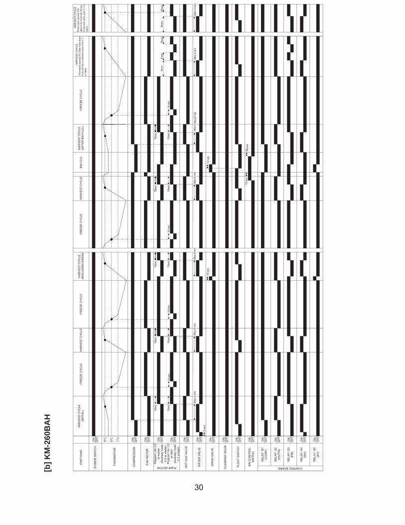
[b] K
M-2
60B
AH
10se
c10
sec
10se
c10
sec
10se
c
10se
c10
sec
10se
c10
sec
10se
c
H
AR
VE
ST
CY
CLE
Ther
mis
tor s
ense
s 9°
Caf
ter 6
min
to 8
min
50
sec
in h
arve
st c
ycle
(Ver
3.1
or
late
r) 6min
60se
c
H
AR
VE
ST
CY
CLE
Ther
mis
tor s
ense
s 9°
C a
fter m
ore
than
8 m
in 5
0 se
c in
har
vest
cyc
le (V
er 3
.1or
late
r) 6min
3min
10se
c
FRE
EZE
CY
CLE
PA
RT
NA
ME
HA
RV
ES
T C
YC
LE(IN
ITIA
L)FR
EE
ZE C
YC
LEH
AR
VE
ST
CY
CLE
(AFT
ER
BIN
FU
LL)
HA
RV
ES
T C
YC
LE(IN
CLU
DIN
G D
RA
IN)
FRE
EZE
CY
CLE
FRE
EZE
CY
CLE
HA
RV
ES
T C
YC
LEB
IN F
ULL
HO
T G
AS
VA
LVE
FAN
MO
TOR
ON
OFF ON
Pro
gram
Ver
2.5
or e
arlie
r(A
uxili
ary
Cod
e:V
-0 o
r ear
lier)
ON
OFF
WA
TER
VA
LVE
ON
OFF
CLE
AN
ING
VA
LVE
ON
OFF
DR
AIN
VA
LVE
FLO
AT
SW
ITC
HO
N
RE
LAY
: X4
(WV
)
ON
ON
OFF ON
OFFON
OFF
OFF ON
OFFON
OFF
CONTROL BOARD
RE
LAY
: X6
(DV
)
RE
LAY
: X1
(CO
MP
)
RE
LAY
: X2
(HV
/FM
)
ON
RE
LAY
: X3
(PM
)O
FF
OFF
BIN
CO
NTR
OL
SW
ITC
HO
NO
FF
OFF
PUMP MOTOR
Pro
gram
Ver
3.2
or la
ter
(Aux
iliar
y C
ode:
V-1
or l
ater
)
PO
WE
R S
WIT
CH
ON
HA
RV
ES
T C
YC
LE
CO
MP
RE
SS
OR
ON
OFF1°C
OFF 9°C
5°C
THE
RM
ISTO
R
Max
6 m
in
5 se
c
Max
6 m
inM
ax 6
min
10 s
ec
Max
6 m
in
15 s
ec
10 s
ec
90 s
ec
Max
6
10 s
ec10
sec
10 s
ec
Max
6 m
in
10 s
ec
Max
6 m
inM
ax 6
min
31
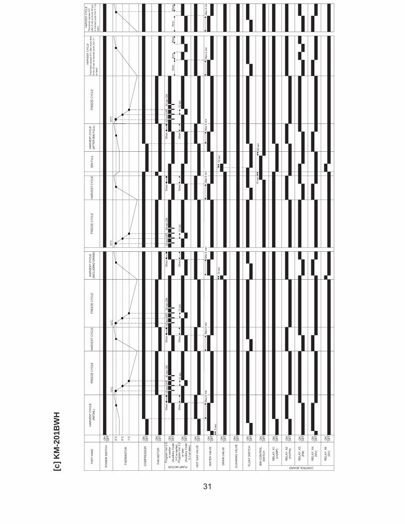
[c] K
M-2
01B
WH
30se
c30
sec
30se
c30
sec
30se
c
30se
c30
sec
30se
c30
sec
30se
c
H
AR
VE
ST
CY
CLE
Ther
mis
tor s
ense
s 9°
C a
fter m
ore
than
8 m
in 3
0 se
c in
har
vest
cyc
le (V
er 3
.1or
late
r)
H
AR
VE
ST
CY
CLE
Ther
mis
tor s
ense
s 9°
Caf
ter 6
min
to 8
min
30
sec
in h
arve
st c
ycle
(Ver
3.1
or
late
r)
6min
3min
30se
c6m
in60
sec
FRE
EZE
CY
CLE
HA
RV
ES
T C
YC
LE(A
FTE
R B
IN F
ULL
)B
IN F
ULL
HA
RV
ES
T C
YC
LEFR
EE
ZE C
YC
LEFR
EE
ZE C
YC
LEH
AR
VE
ST
CY
CLE
(INC
LUD
ING
DR
AIN
)
DR
AIN
VA
LVE
HO
T G
AS
VA
LVE
WA
TER
VA
LVE
ON
OFF
OFF
CLE
AN
ING
VA
LVE
ON
OFF
FLO
AT
SW
ITC
HO
NO
FF
BIN
CO
NTR
OL
SW
ITC
HO
NO
FF
RE
LAY
: X4
(WV
)
ON
ON
OFF ON
OFFON
OFF
OFF ON
OFFON
OFF
CONTROL BOARD
RE
LAY
: X6
(DV
)
RE
LAY
: X1
(CO
MP
)
RE
LAY
: X2
(HV
/FM
)
ON
RE
LAY
: X3
(PM
)O
FF
FAN
MO
TOR
ON
OFF ON
Pro
gram
Ver
2.5
or e
arlie
r(A
uxili
ary
Cod
e:V
-0 o
r ear
lier)
ON
OFF
PUMP MOTOR
Pro
gram
Ver
3.2
or la
ter
(Aux
iliar
y C
ode:
V-1
or l
ater
)
PO
WE
R S
WIT
CH
ON
HA
RV
ES
T C
YC
LEFR
EE
ZE C
YC
LEH
AR
VE
ST
CY
CLE
(INIT
IAL)
OFF
PA
RT
NA
ME
9°C
5°C
THE
RM
ISTO
R
CO
MP
RE
SS
OR
ON
OFF1°C
Max
6 m
in
5 se
c
Max
6 m
inM
ax 6
min
10 s
ec
Max
6 m
in
15 s
ec
10 s
ec
90 s
ec
Max
6 m
in
10 s
ec10
sec
10 s
ec
10 s
ec O
FF,
50
sec
ON
10 s
ec O
FF,
50
sec
ON
10 s
ec O
FF,
50
sec
ON
10°C
10°C
10°C
10 s
ec
10 s
ec O
FF,
50
sec
ON
10°C
Max
6 m
inM
ax 6
min
32
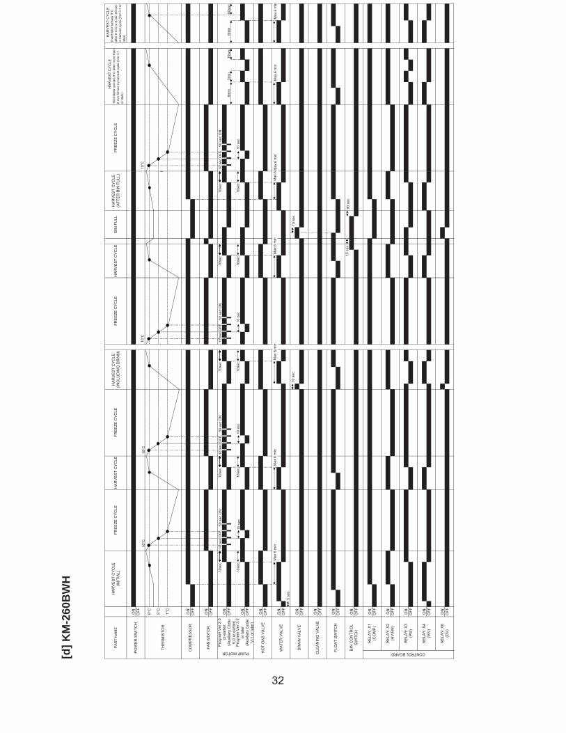
[d] K
M-2
60B
WH
10se
c10
sec
10se
c10
sec
10se
c
10se
c10
sec
10se
c10
sec
10se
c
H
AR
VE
ST
CY
CLE
Ther
mis
tor s
ense
s 9°
Caf
ter 6
min
to 8
min
50
sec
in h
arve
st c
ycle
(Ver
3.1
or
late
r)
6min
3min
10se
c6m
in60
sec
PA
RT
NA
ME
FRE
EZE
CY
CLE
HA
RV
ES
T C
YC
LE(IN
CLU
DIN
G D
RA
IN)
FRE
EZE
CY
CLE
HO
T G
AS
VA
LVE
WA
TER
VA
LVE
ON
OFF
CLE
AN
ING
VA
LVE
HA
RV
ES
T C
YC
LE(A
FTE
R B
IN F
ULL
)B
IN F
ULL
HA
RV
ES
T C
YC
LE
OFF
DR
AIN
VA
LVE
ON
ON
OFF ON
OFF ON
RE
LAY
: X3
(PM
)
OFFON
OFF ON
RE
LAY
: X4
(WV
)
FLO
AT
SW
ITC
HO
NO
FF
BIN
CO
NTR
OL
SW
ITC
HO
NO
FF
OFFON
OFF
CONTROL BOARD
RE
LAY
: X6
(DV
)
RE
LAY
: X1
(CO
MP
)
RE
LAY
: X2
(HV
/FM
)
FAN
MO
TOR
ON
OFF ON
Pro
gram
Ver
2.5
or e
arlie
r(A
uxili
ary
Cod
e:V
-0 o
r ear
lier)
ON
OFF
PUMP MOTOR
Pro
gram
Ver
3.2
or la
ter
(Aux
iliar
y C
ode:
V-1
or l
ater
)O
FF
FRE
EZE
CY
CLE
H
AR
VE
ST
CY
CLE
Ther
mis
tor s
ense
s 9°
C a
fter m
ore
than
8 m
in 5
0 se
c in
har
vest
cyc
le (V
er 3
.1or
late
r)
ON
HA
RV
ES
T C
YC
LEFR
EE
ZE C
YC
LEH
AR
VE
ST
CY
CLE
(INIT
IAL)
OFFON
OFF 9°C
5°C
PO
WE
R S
WIT
CH
THE
RM
ISTO
R
ON
OFF1°C
CO
MP
RE
SS
OR
Max
6 m
in
5 se
c
Max
6 m
inM
ax 6
min
10 s
ec
Max
6 m
in
15 s
ec
10 s
ec
90 s
ec
Max
6 m
in
10 s
ec10
sec
10 s
ec
10 s
ec O
FF,
50
sec
ON
10 s
ec O
FF,
50
sec
ON
10 s
ec O
FF,
50
sec
ON
10°C
10°C
10°C
Max
6 m
inM
ax 6
min
10 s
ec
10 s
ec O
FF,
50
sec
ON
10°C
Max
6 m
inM
ax 6
min
33
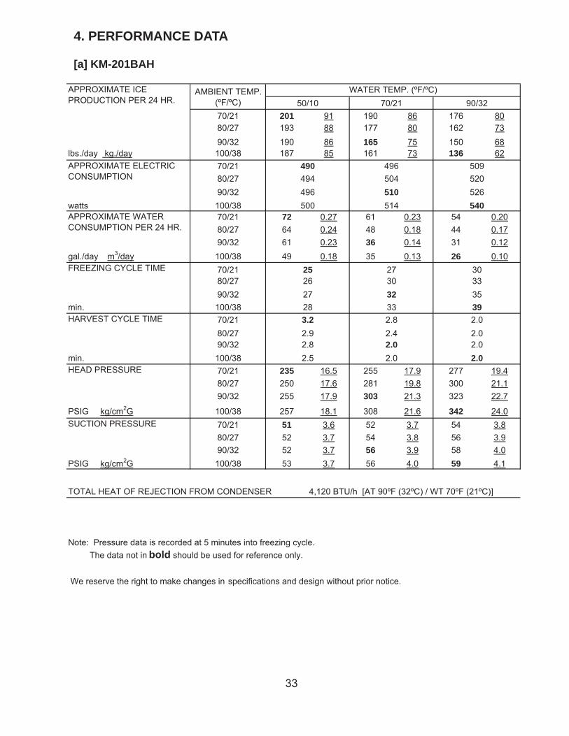
4. PERFORMANCE DATA
[a] KM-201BAH
70/21 201 91 190 86 176 8080/27 193 88 177 80 162 7390/32 190 86 165 75 150 68
lbs./day kg./day 100/38 187 85 161 73 136 6270/2180/2790/32
watts 100/3870/21 72 0.27 61 0.23 54 0.2080/27 64 0.24 48 0.18 44 0.1790/32 61 0.23 36 0.14 31 0.12
gal./day m3/day 100/38 49 0.18 35 0.13 26 0.1070/2180/2790/32
min. 100/3870/2180/2790/32
min. 100/3870/21 235 16.5 255 17.9 277 19.480/27 250 17.6 281 19.8 300 21.190/32 255 17.9 303 21.3 323 22.7
PSIG kg/cm2G 100/38 257 18.1 308 21.6 342 24.070/21 51 3.6 52 3.7 54 3.880/27 52 3.7 54 3.8 56 3.990/32 52 3.7 56 3.9 58 4.0
PSIG kg/cm2G 100/38 53 3.7 56 4.0 59 4.1
Note: Pressure data is recorded at 5 minutes into freezing cycle. The data not in bold should be used for reference only.
We reserve the right to make changes in specifications and design without prior notice.
262730
2.0
3.2
2.5
2.82.42.0
2.9
25
APPROXIMATE ICEPRODUCTION PER 24 HR.
APPROXIMATE ELECTRICCONSUMPTION
APPROXIMATE WATERCONSUMPTION PER 24 HR.
FREEZING CYCLE TIME
WATER TEMP. (ºF/ºC)AMBIENT TEMP.(ºF/ºC) 50/10 70/21 90/32
500
496504510514
490494496
30333539
509520526540
332728
32
2.0
SUCTION PRESSURE
HARVEST CYCLE TIME
HEAD PRESSURE
2.02.0
2.8 2.0
TOTAL HEAT OF REJECTION FROM CONDENSER 4,120 BTU/h [AT 90ºF (32ºC) / WT 70ºF (21ºC)]
34
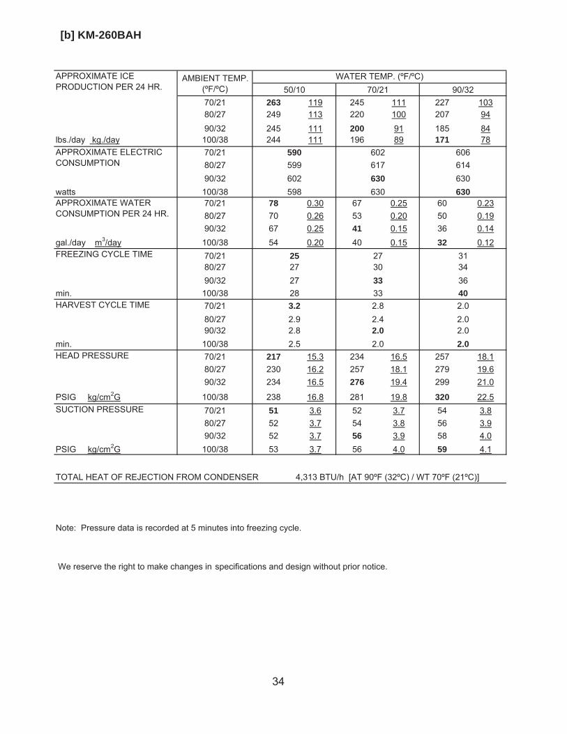
[b] KM-260BAH
70/21 263 119 245 111 227 10380/27 249 113 220 100 207 9490/32 245 111 200 91 185 84
lbs./day kg./day 100/38 244 111 196 89 171 7870/2180/2790/32
watts 100/3870/21 78 0.30 67 0.25 60 0.2380/27 70 0.26 53 0.20 50 0.1990/32 67 0.25 41 0.15 36 0.14
gal./day m3/day 100/38 54 0.20 40 0.15 32 0.1270/2180/2790/32
min. 100/3870/2180/2790/32
min. 100/3870/21 217 15.3 234 16.5 257 18.180/27 230 16.2 257 18.1 279 19.690/32 234 16.5 276 19.4 299 21.0
PSIG kg/cm2G 100/38 238 16.8 281 19.8 320 22.570/21 51 3.6 52 3.7 54 3.880/27 52 3.7 54 3.8 56 3.990/32 52 3.7 56 3.9 58 4.0
PSIG kg/cm2G 100/38 53 3.7 56 4.0 59 4.1
Note: Pressure data is recorded at 5 minutes into freezing cycle.
We reserve the right to make changes in specifications and design without prior notice.
272730
2.0
3.2
2.5
2.82.42.0
2.9
25
APPROXIMATE ICEPRODUCTION PER 24 HR.
APPROXIMATE ELECTRICCONSUMPTION
APPROXIMATE WATERCONSUMPTION PER 24 HR.
FREEZING CYCLE TIME
WATER TEMP. (ºF/ºC)AMBIENT TEMP.(ºF/ºC) 50/10 70/21 90/32
598
602617630630
590599602
31343640
606614630630
332728
33
2.0
SUCTION PRESSURE
HARVEST CYCLE TIME
HEAD PRESSURE
2.02.0
2.8 2.0
TOTAL HEAT OF REJECTION FROM CONDENSER 4,313 BTU/h [AT 90ºF (32ºC) / WT 70ºF (21ºC)]
35
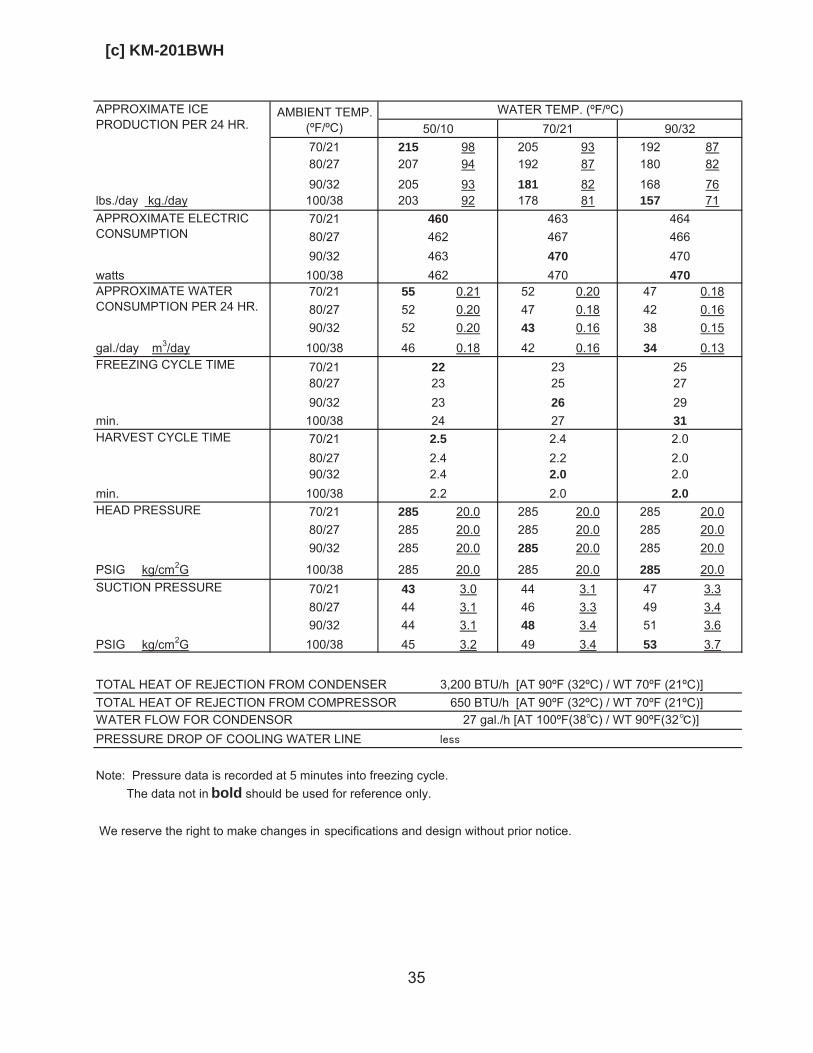
[c] KM-201BWH
70/21 215 98 205 93 192 8780/27 207 94 192 87 180 8290/32 205 93 181 82 168 76
lbs./day kg./day 100/38 203 92 178 81 157 7170/2180/2790/32
watts 100/3870/21 55 0.21 52 0.20 47 0.1880/27 52 0.20 47 0.18 42 0.1690/32 52 0.20 43 0.16 38 0.15
gal./day m3/day 100/38 46 0.18 42 0.16 34 0.1370/2180/2790/32
min. 100/3870/2180/2790/32
min. 100/3870/21 285 20.0 285 20.0 285 20.080/27 285 20.0 285 20.0 285 20.090/32 285 20.0 285 20.0 285 20.0
PSIG kg/cm2G 100/38 285 20.0 285 20.0 285 20.070/21 43 3.0 44 3.1 47 3.380/27 44 3.1 46 3.3 49 3.490/32 44 3.1 48 3.4 51 3.6
PSIG kg/cm2G 100/38 45 3.2 49 3.4 53 3.7
Note: Pressure data is recorded at 5 minutes into freezing cycle. The data not in bold should be used for reference only.
We reserve the right to make changes in specifications and design without prior notice.
WATER FLOW FOR CONDENSOR 27 gal./h [AT 100ºF(38 ) / WT 90ºF(32 )]PRESSURE DROP OF COOLING WATER LINE
232325
2.0
2.5
2.2
2.42.22.0
2.4
22
APPROXIMATE ICEPRODUCTION PER 24 HR.
APPROXIMATE ELECTRICCONSUMPTION
APPROXIMATE WATERCONSUMPTION PER 24 HR.
FREEZING CYCLE TIME
WATER TEMP. (ºF/ºC)AMBIENT TEMP.(ºF/ºC) 50/10 70/21 90/32
462
463467470470
460462463
25272931
464466470470
272324
26
2.0
SUCTION PRESSURE
HARVEST CYCLE TIME
HEAD PRESSURE
2.02.0
2.4 2.0
TOTAL HEAT OF REJECTION FROM CONDENSER 3,200 BTU/h [AT 90ºF (32ºC) / WT 70ºF (21ºC)]TOTAL HEAT OF REJECTION FROM COMPRESSOR 650 BTU/h [AT 90ºF (32ºC) / WT 70ºF (21ºC)]
36
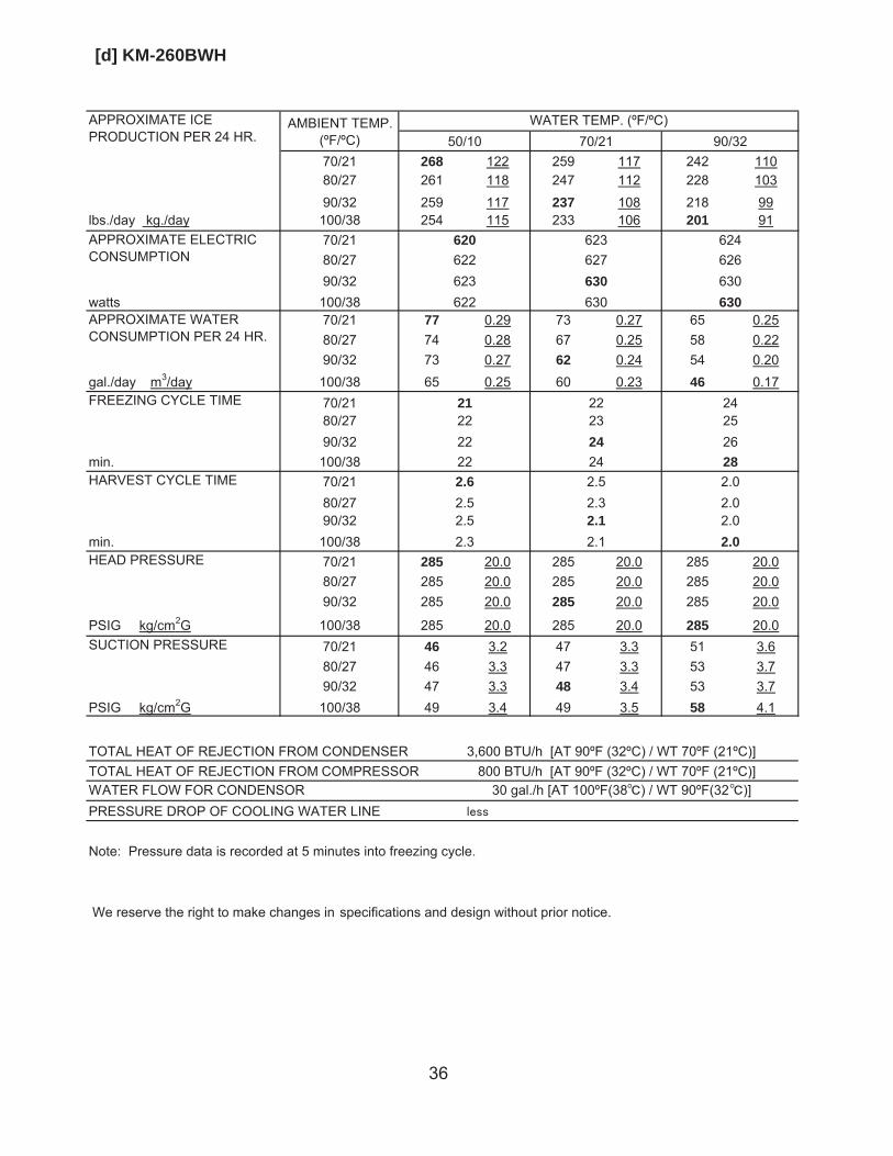
[d] KM-260BWH
70/21 268 122 259 117 242 11080/27 261 118 247 112 228 10390/32 259 117 237 108 218 99
lbs./day kg./day 100/38 254 115 233 106 201 9170/2180/2790/32
watts 100/3870/21 77 0.29 73 0.27 65 0.2580/27 74 0.28 67 0.25 58 0.2290/32 73 0.27 62 0.24 54 0.20
gal./day m3/day 100/38 65 0.25 60 0.23 46 0.1770/2180/2790/32
min. 100/3870/2180/2790/32
min. 100/3870/21 285 20.0 285 20.0 285 20.080/27 285 20.0 285 20.0 285 20.090/32 285 20.0 285 20.0 285 20.0
PSIG kg/cm2G 100/38 285 20.0 285 20.0 285 20.070/21 46 3.2 47 3.3 51 3.680/27 46 3.3 47 3.3 53 3.790/32 47 3.3 48 3.4 53 3.7
PSIG kg/cm2G 100/38 49 3.4 49 3.5 58 4.1
Note: Pressure data is recorded at 5 minutes into freezing cycle.
We reserve the right to make changes in specifications and design without prior notice.
222223
2.1
2.6
2.3
2.52.32.1
2.5
21
APPROXIMATE ICEPRODUCTION PER 24 HR.
APPROXIMATE ELECTRICCONSUMPTION
APPROXIMATE WATERCONSUMPTION PER 24 HR.
FREEZING CYCLE TIME
WATER TEMP. (ºF/ºC)AMBIENT TEMP.(ºF/ºC) 50/10 70/21 90/32
622
623627630630
620622623
24252628
624626630630
242222
24
2.0
SUCTION PRESSURE
HARVEST CYCLE TIME
HEAD PRESSURE
2.02.0
2.5 2.0
TOTAL HEAT OF REJECTION FROM CONDENSER 3,600 BTU/h [AT 90ºF (32ºC) / WT 70ºF (21ºC)]TOTAL HEAT OF REJECTION FROM COMPRESSOR 800 BTU/h [AT 90ºF (32ºC) / WT 70ºF (21ºC)]WATER FLOW FOR CONDENSOR 30 gal./h [AT 100ºF(38 ) / WT 90ºF(32 )]PRESSURE DROP OF COOLING WATER LINE
37
IV. SERVICE DIAGNOSIS
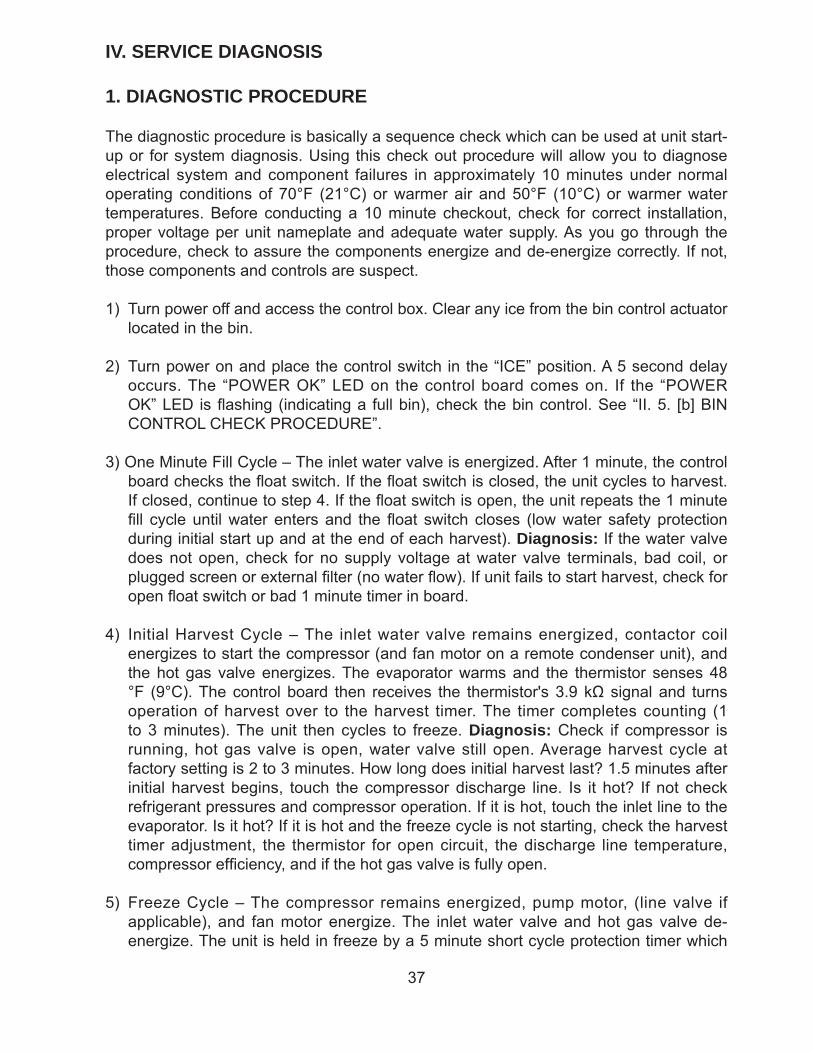
1. DIAGNOSTIC PROCEDURE
The diagnostic procedure is basically a sequence check which can be used at unit start-up or for system diagnosis. Using this check out procedure will allow you to diagnose electrical system and component failures in approximately 10 minutes under normal operating conditions of 70°F (21°C) or warmer air and 50°F (10°C) or warmer water temperatures. Before conducting a 10 minute checkout, check for correct installation, proper voltage per unit nameplate and adequate water supply. As you go through the procedure, check to assure the components energize and de-energize correctly. If not, those components and controls are suspect.
1) Turn power off and access the control box. Clear any ice from the bin control actuator located in the bin.
2) Turn power on and place the control switch in the “ICE” position. A 5 second delay occurs. The “POWER OK” LED on the control board comes on. If the “POWER OK” LED is fl ashing (indicating a full bin), check the bin control. See “II. 5. [b] BIN CONTROL CHECK PROCEDURE”.
3) One Minute Fill Cycle – The inlet water valve is energized. After 1 minute, the control board checks the fl oat switch. If the fl oat switch is closed, the unit cycles to harvest. If closed, continue to step 4. If the fl oat switch is open, the unit repeats the 1 minute fi ll cycle until water enters and the fl oat switch closes (low water safety protection during initial start up and at the end of each harvest). Diagnosis: If the water valve does not open, check for no supply voltage at water valve terminals, bad coil, or plugged screen or external fi lter (no water fl ow). If unit fails to start harvest, check for open fl oat switch or bad 1 minute timer in board.
4) Initial Harvest Cycle – The inlet water valve remains energized, contactor coil energizes to start the compressor (and fan motor on a remote condenser unit), and the hot gas valve energizes. The evaporator warms and the thermistor senses 48°F (9°C). The control board then receives the thermistor's 3.9 kΩ signal and turns operation of harvest over to the harvest timer. The timer completes counting (1 to 3 minutes). The unit then cycles to freeze. Diagnosis: Check if compressor is running, hot gas valve is open, water valve still open. Average harvest cycle at factory setting is 2 to 3 minutes. How long does initial harvest last? 1.5 minutes after initial harvest begins, touch the compressor discharge line. Is it hot? If not check refrigerant pressures and compressor operation. If it is hot, touch the inlet line to the evaporator. Is it hot? If it is hot and the freeze cycle is not starting, check the harvest timer adjustment, the thermistor for open circuit, the discharge line temperature, compressor effi ciency, and if the hot gas valve is fully open.
5) Freeze Cycle – The compressor remains energized, pump motor, (line valve if applicable), and fan motor energize. The inlet water valve and hot gas valve de-energize. The unit is held in freeze by a 5 minute short cycle protection timer which
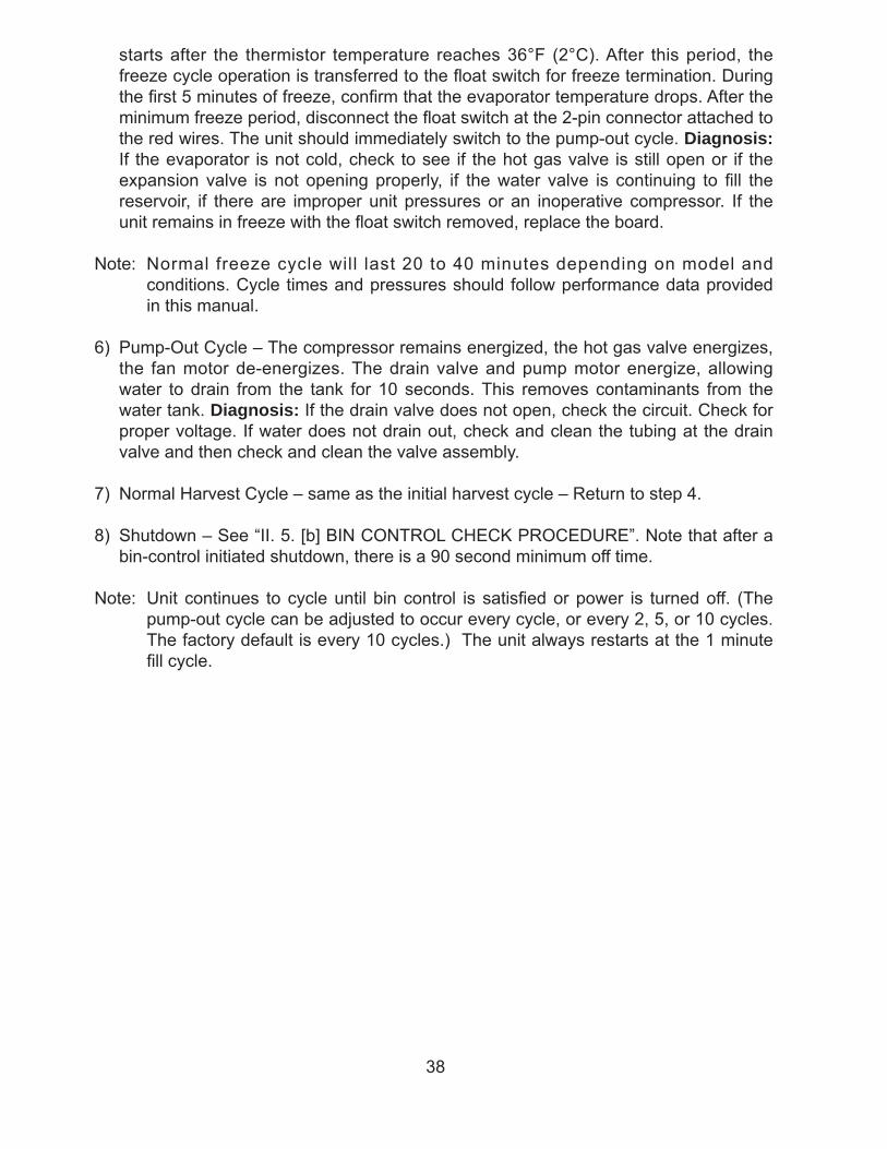
38
starts after the thermistor temperature reaches 36°F (2°C). After this period, the freeze cycle operation is transferred to the fl oat switch for freeze termination. During the fi rst 5 minutes of freeze, confi rm that the evaporator temperature drops. After the minimum freeze period, disconnect the fl oat switch at the 2-pin connector attached to the red wires. The unit should immediately switch to the pump-out cycle. Diagnosis: If the evaporator is not cold, check to see if the hot gas valve is still open or if the expansion valve is not opening properly, if the water valve is continuing to fi ll the reservoir, if there are improper unit pressures or an inoperative compressor. If the unit remains in freeze with the fl oat switch removed, replace the board.
Note: Normal freeze cycle will last 20 to 40 minutes depending on model and conditions. Cycle times and pressures should follow performance data provided in this manual.
6) Pump-Out Cycle – The compressor remains energized, the hot gas valve energizes, the fan motor de-energizes. The drain valve and pump motor energize, allowing water to drain from the tank for 10 seconds. This removes contaminants from the water tank. Diagnosis: If the drain valve does not open, check the circuit. Check for proper voltage. If water does not drain out, check and clean the tubing at the drain valve and then check and clean the valve assembly.
7) Normal Harvest Cycle – same as the initial harvest cycle – Return to step 4.
8) Shutdown – See “II. 5. [b] BIN CONTROL CHECK PROCEDURE”. Note that after a bin-control initiated shutdown, there is a 90 second minimum off time.
Note: Unit continues to cycle until bin control is satisfi ed or power is turned off. (The pump-out cycle can be adjusted to occur every cycle, or every 2, 5, or 10 cycles. The factory default is every 10 cycles.) The unit always restarts at the 1 minute fi ll cycle.
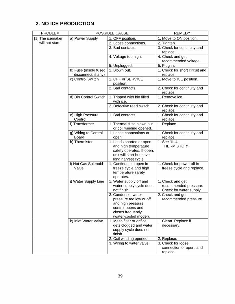
39
2. NO ICE PRODUCTION
PROBLEM POSSIBLE CAUSE REMEDY 1. OFF position. 1. Move to ON position. 2. Loose connections. 2. Tighten. 3. Bad contacts. 3. Check for continuity and
replace. 4. Voltage too high. 4. Check and get
recommended voltage.
a) Power Supply
5. Unplugged. 5. Plug in. b) Fuse (inside fused
disconnect, if any)1. Blown out. 1. Check for short circuit and
replace. 1. OFF or SERVICE
position. 1. Move to ICE position. c) Control Switch
2. Bad contacts. 2. Check for continuity and replace.
1. Tripped with bin filled with ice.
1. Remove ice. d) Bin Control Switch
2. Defective reed switch. 2. Check for continuity and replace.
e) High Pressure Control
1. Bad contacts. 1. Check for continuity and replace.
f) Transformer 1. Thermal fuse blown out or coil winding opened.
1. Replace.
g) Wiring to Control Board
1. Loose connections or open.
1. Check for continuity and replace.
h) Thermistor 1. Leads shorted or open and high temperature safety operates. If open, unit will start but have long harvest cycle.
1. See “II. 4. THERMISTOR”.
i) Hot Gas Solenoid Valve
1. Continues to open in freeze cycle and high temperature safety operates.
1. Check for power off in freeze cycle and replace.
1. Water supply off and water supply cycle does not finish.
1. Check and get recommended pressure. Check for water supply.
j) Water Supply Line
2. Condenser water pressure too low or off and high pressure control opens and closes frequently (water-cooled model).
2. Check and get recommended pressure.
1. Mesh filter or orifice gets clogged and water supply cycle does not finish.
1. Clean. Replace if necessary.
2. Coil winding opened. 2. Replace.
[1] The icemaker will not start.
k) Inlet Water Valve
3. Wiring to water valve. 3. Check for loose connection or open, and replace.
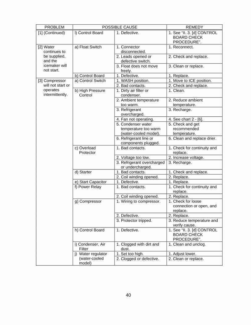
40
PROBLEM POSSIBLE CAUSE REMEDY [1] (Continued) l) Control Board 1. Defective. 1. See “II. 3. [d] CONTROL
BOARD CHECK PROCEDURE”.
1. Connector disconnected.
1. Reconnect.
2. Leads opened or defective switch.
2. Check and replace.
a) Float Switch
3. Float does not move freely.
3. Clean or replace.
[2] Water continues to be supplied, and the icemaker will not start.
b) Control Board 1. Defective. 1. Replace. 1. WASH position. 1. Move to ICE position. a) Control Switch 2. Bad contacts. 2. Check and replace. 1. Dirty air filter or
condenser. 1. Clean.
2. Ambient temperature too warm.
2. Reduce ambient temperature.
3. Refrigerant overcharged.
3. Recharge.
4. Fan not operating. 4. See chart 2 - [6]. 5. Condenser water
temperature too warm (water-cooled model).
5. Check and get recommended temperature.
b) High Pressure Control
6. Refrigerant line or components plugged.
6. Clean and replace drier.
1. Bad contacts. 1. Check for continuity and replace.
2. Voltage too low. 2. Increase voltage.
c) Overload Protector
3. Refrigerant overcharged or undercharged.
3. Recharge.
1. Bad contacts. 1. Check and replace. d) Starter 2. Coil winding opened. 2. Replace.
e) Start Capacitor 1. Defective. 1. Replace. 1. Bad contacts. 1. Check for continuity and
replace. f) Power Relay
2. Coil winding opened. 2. Replace. 1. Wiring to compressor. 1. Check for loose
connection or open, and replace.
2. Defective. 2. Replace.
g) Compressor
3. Protector tripped. 3. Reduce temperature and verify cause.
h) Control Board 1. Defective. 1. See “II. 3. [d] CONTROL BOARD CHECK PROCEDURE”.
i) Condenser, Air Filter
1. Clogged with dirt and dust.
1. Clean and unclog.
1. Set too high. 1. Adjust lower.
[3] Compressor will not start or operates intermittently.
j) Water regulator (water-cooled model)
2. Clogged or defective. 2. Clean or replace.
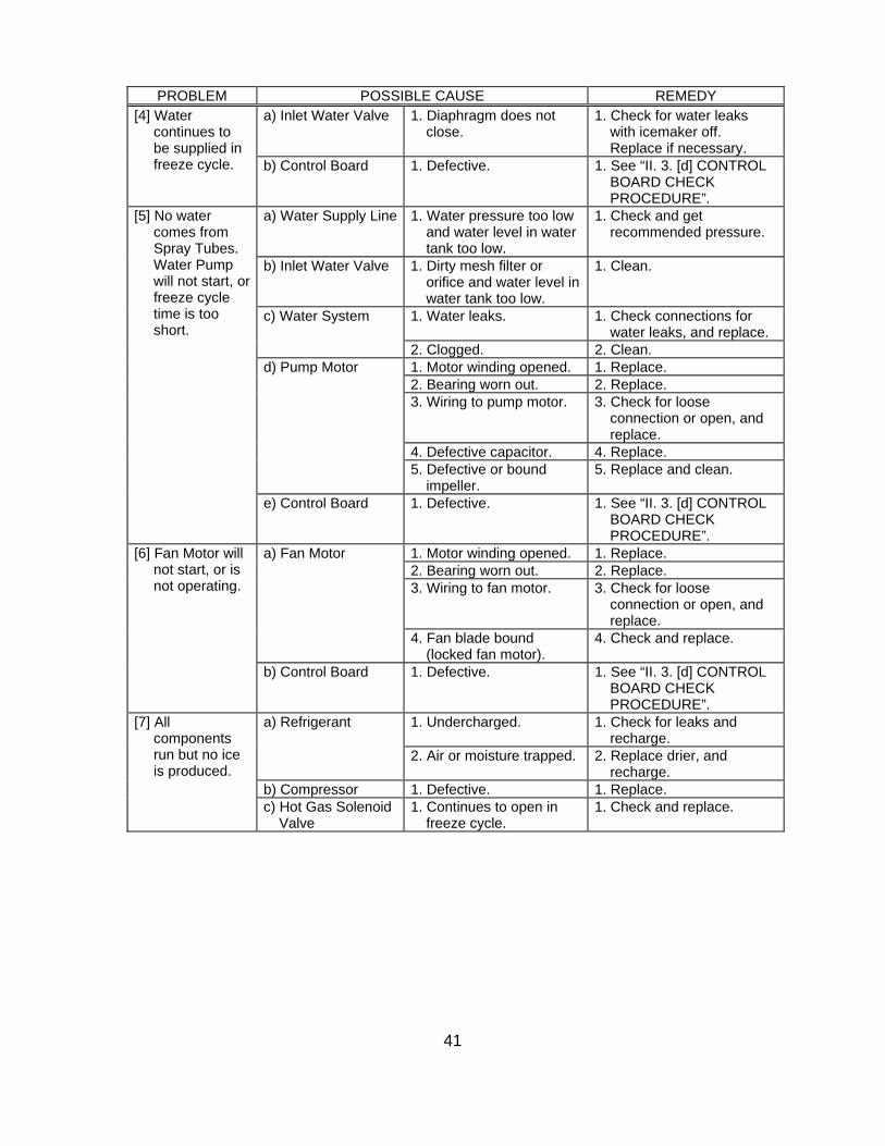
41
PROBLEM POSSIBLE CAUSE REMEDY a) Inlet Water Valve 1. Diaphragm does not
close. 1. Check for water leaks
with icemaker off. Replace if necessary.
[4] Water continues to be supplied in freeze cycle. b) Control Board 1. Defective. 1. See “II. 3. [d] CONTROL
BOARD CHECK PROCEDURE”.
a) Water Supply Line 1. Water pressure too low and water level in water tank too low.
1. Check and get recommended pressure.
b) Inlet Water Valve 1. Dirty mesh filter or orifice and water level in water tank too low.
1. Clean.
1. Water leaks. 1. Check connections for water leaks, and replace.
c) Water System
2. Clogged. 2. Clean. 1. Motor winding opened. 1. Replace. 2. Bearing worn out. 2. Replace. 3. Wiring to pump motor. 3. Check for loose
connection or open, and replace.
4. Defective capacitor. 4. Replace.
d) Pump Motor
5. Defective or bound impeller.
5. Replace and clean.
[5] No water comes from Spray Tubes. Water Pump will not start, or freeze cycle time is too short.
e) Control Board 1. Defective. 1. See “II. 3. [d] CONTROL BOARD CHECK PROCEDURE”.
1. Motor winding opened. 1. Replace. 2. Bearing worn out. 2. Replace. 3. Wiring to fan motor. 3. Check for loose
connection or open, and replace.
a) Fan Motor
4. Fan blade bound (locked fan motor).
4. Check and replace.
[6] Fan Motor will not start, or is not operating.
b) Control Board 1. Defective. 1. See “II. 3. [d] CONTROL BOARD CHECK PROCEDURE”.
1. Undercharged. 1. Check for leaks and recharge.
a) Refrigerant
2. Air or moisture trapped. 2. Replace drier, and recharge.
b) Compressor 1. Defective. 1. Replace.
[7] All components run but no ice is produced.
c) Hot Gas Solenoid Valve
1. Continues to open in freeze cycle.
1. Check and replace.
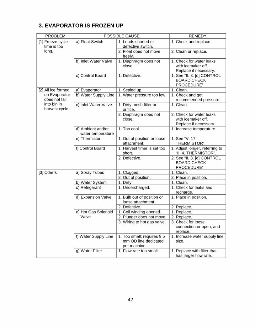
42
3. EVAPORATOR IS FROZEN UP
PROBLEM POSSIBLE CAUSE REMEDY 1. Leads shorted or
defective switch. 1. Check and replace. a) Float Switch
2. Float does not move freely.
2. Clean or replace.
b) Inlet Water Valve 1. Diaphragm does not close.
1. Check for water leaks with icemaker off. Replace if necessary.
[1] Freeze cycle time is too long.
c) Control Board 1. Defective. 1. See “II. 3. [d] CONTROL BOARD CHECK PROCEDURE”.
a) Evaporator 1. Scaled up. 1. Clean. b) Water Supply Line 1. Water pressure too low. 1. Check and get
recommended pressure. 1. Dirty mesh filter or
orifice. 1. Clean. c) Inlet Water Valve
2. Diaphragm does not close.
2. Check for water leaks with icemaker off. Replace if necessary.
d) Ambient and/or water temperature
1. Too cool. 1. Increase temperature.
e) Thermistor 1. Out of position or loose attachment.
1. See “V. 17. THERMISTOR”.
1. Harvest timer is set too short.
1. Adjust longer, referring to “II. 4. THERMISTOR”.
[2] All ice formed on Evaporator does not fall into bin in harvest cycle.
f) Control Board
2. Defective. 2. See “II. 3. [d] CONTROL BOARD CHECK PROCEDURE”.
1. Clogged. 1. Clean. a) Spray Tubes 2. Out of position. 2. Place in position.
b) Water System 1. Dirty. 1. Clean. c) Refrigerant 1. Undercharged. 1. Check for leaks and
recharge. 1. Bulb out of position or
loose attachment. 1. Place in position. d) Expansion Valve
2. Defective. 2. Replace. 1. Coil winding opened. 1. Replace. 2. Plunger does not move. 2. Replace.
e) Hot Gas Solenoid Valve
3. Wiring to hot gas valve. 3. Check for loose connection or open, and replace.
f) Water Supply Line 1. Too small; requires 9.5 mm OD line dedicated per machine.
1. Increase water supply line size.
[3] Others
g) Water Filter 1. Flow rate too small. 1. Replace with filter that has larger flow rate.
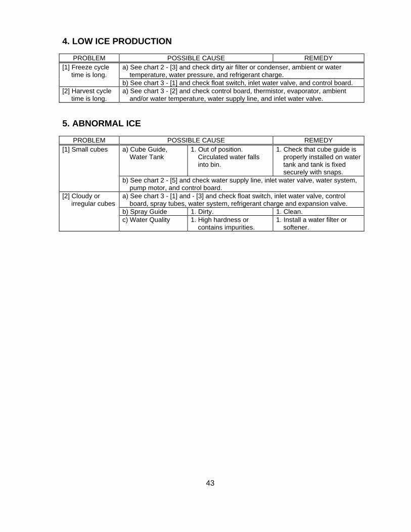
43
4. LOW ICE PRODUCTION
PROBLEM POSSIBLE CAUSE REMEDY a) See chart 2 - [3] and check dirty air filter or condenser, ambient or water
temperature, water pressure, and refrigerant charge. [1] Freeze cycle
time is long. b) See chart 3 - [1] and check float switch, inlet water valve, and control board.
[2] Harvest cycle time is long.
a) See chart 3 - [2] and check control board, thermistor, evaporator, ambient and/or water temperature, water supply line, and inlet water valve.
5. ABNORMAL ICE
PROBLEM POSSIBLE CAUSE REMEDY a) Cube Guide,
Water Tank 1. Out of position.
Circulated water falls into bin.
1. Check that cube guide is properly installed on water tank and tank is fixed securely with snaps.
[1] Small cubes
b) See chart 2 - [5] and check water supply line, inlet water valve, water system, pump motor, and control board.
a) See chart 3 - [1] and - [3] and check float switch, inlet water valve, control board, spray tubes, water system, refrigerant charge and expansion valve.
b) Spray Guide 1. Dirty. 1. Clean.
[2] Cloudy or irregular cubes
c) Water Quality 1. High hardness or contains impurities.
1. Install a water filter or softener.
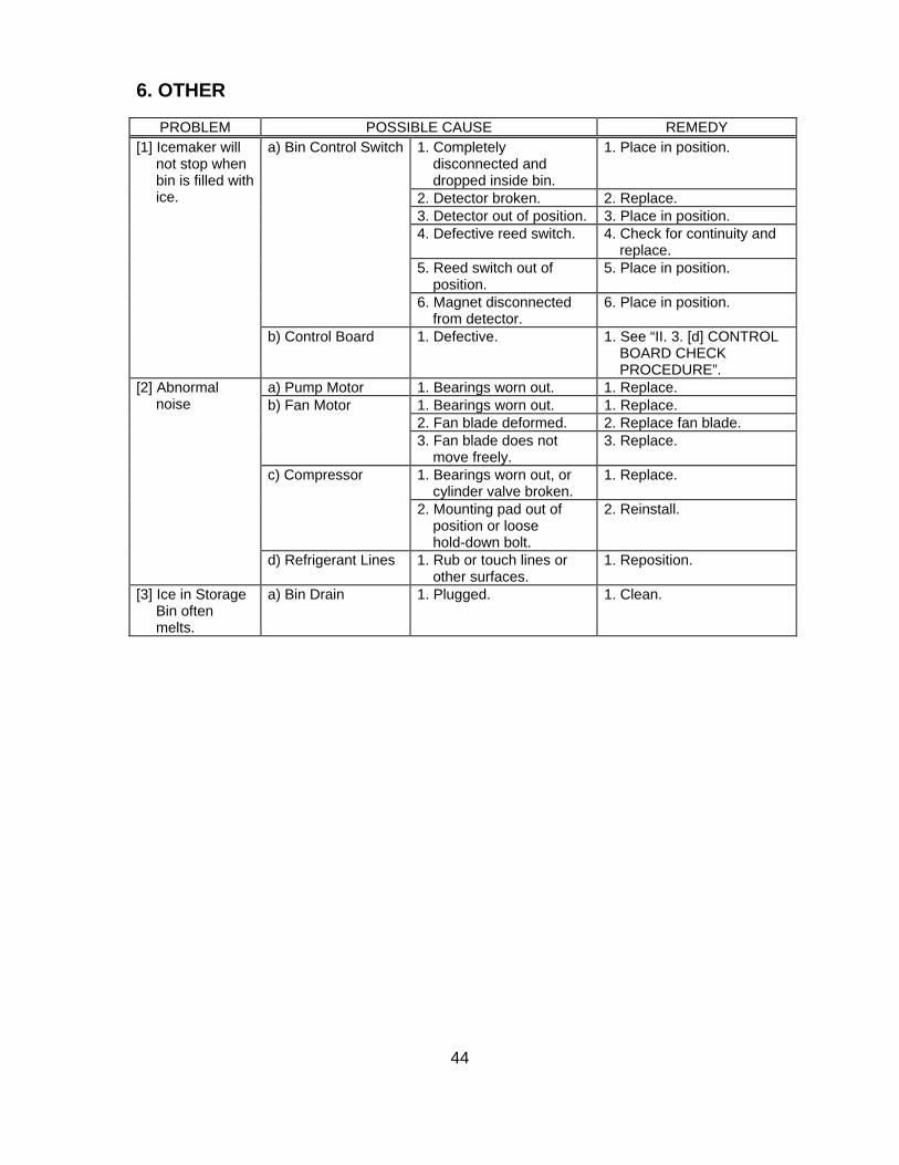
44
6. OTHER
PROBLEM POSSIBLE CAUSE REMEDY 1. Completely
disconnected and dropped inside bin.
1. Place in position.
2. Detector broken. 2. Replace. 3. Detector out of position. 3. Place in position. 4. Defective reed switch. 4. Check for continuity and
replace. 5. Reed switch out of
position. 5. Place in position.
a) Bin Control Switch
6. Magnet disconnected from detector.
6. Place in position.
[1] Icemaker will not stop when bin is filled with ice.
b) Control Board 1. Defective. 1. See “II. 3. [d] CONTROL BOARD CHECK PROCEDURE”.
a) Pump Motor 1. Bearings worn out. 1. Replace. 1. Bearings worn out. 1. Replace. 2. Fan blade deformed. 2. Replace fan blade.
b) Fan Motor
3. Fan blade does not move freely.
3. Replace.
1. Bearings worn out, or cylinder valve broken.
1. Replace. c) Compressor
2. Mounting pad out of position or loose hold-down bolt.
2. Reinstall.
[2] Abnormal noise
d) Refrigerant Lines 1. Rub or touch lines or other surfaces.
1. Reposition.
[3] Ice in Storage Bin often melts.
a) Bin Drain 1. Plugged. 1. Clean.
45
V. REMOVAL AND REPLACEMENT
WARNING
1. This unit should be diagnosed and repaired only by qualified service personnel to reduce the risk of death, electric shock, serious injury, or fi re.
2. Move the control switch to the “OFF” position and turn off the power supply before servicing.
3. CHOKING HAZARD: Ensure al l components, fasteners, and thumbscrews are securely in place after the unit is serviced. Make sure that none have fallen into the storage bin.
4. Make sure all food zones in the icemaker and storage bin are clean after the unit is serviced. For cleaning procedures, see “VI. CLEANING AND MAINTENANCE INSTRUCTIONS”.
1. SERVICE FOR REFRIGERANT LINES
[a] SERVICE INFORMATION
WARNING
1. Repairs requiring the refrigeration circuit to be opened must be performed by properly trained and EPA-certifi ed service personnel.
2. Always recover the refrigerant and store it in an approved container. Do not discharge the refrigerant into the atmosphere.
3. Use an electronic leak detector or soap bubbles to check for leaks. Add a trace of refrigerant to the system (if using an electronic leak detector), and then raise the pressure using nitrogen gas (140 PSIG). DO NOT use R-404A as a mixture with pressurized air for leak testing.
CAUTION
1. Do not leave the system open for longer than 15 minutes when replacing or servicing parts. The Polyol Ester (POE) oils used in R-404A units can absorb moisture quickly. Therefore it is important to prevent moisture from entering the system when replacing or servicing parts.
2. Always install a new drier every time the sealed refrigeration system is opened.
46
3. Do not replace the drier until after all other repair or replacement has been made. Install the new drier with the arrow on the drier in the direction of the refrigerant fl ow.
4. When brazing, protect the drier by using a wet cloth to prevent the drier from overheating. Do not allow the drier to exceed 250°F (121°C).
[b] REFRIGERANT RECOVERY
The icemaker unit is provided with refrigerant access valves. Using proper refrigerant practices, recover the refrigerant from the access valves and store it in an approved container. Do not discharge the refrigerant into the atmosphere.
[c] EVACUATION AND RECHARGE (R-404A)
1) Attach a vacuum pump to the system. Be sure to connect the charging hoses to both high and low-side access valves.
IMPORTANT
The vacuum level and vacuum pump may be the same as those for current refrigerants. However, the rubber hose and gauge manifold to be used for evacuation and refrigerant charge should be exclusively for POE oils.
2) Turn on the vacuum pump. Open the gauge manifold valves. Never allow the oil in the vacuum pump to fl ow backwards.
3) Allow the vacuum pump to pull down to a 29.9” Hg vacuum. Evacuating period depends on pump capacity.
4) Close the low-side valve and high-side valve on the gauge manifold.
5) Disconnect the gauge manifold hose from the vacuum pump and attach it to a refrigerant service cylinder. Remember to loosen the connection and purge the air from the hose. For air-cooled and water-cooled models, see the nameplate for the required refrigerant charge. For remote air-cooled model, see the rating label inside the icemaker. Hoshizaki recommends only virgin refrigerant or reclaimed refrigerant which meets ARI Standard 700 (latest edition) be used.
6) A liquid charge is recommended for charging an R-404A system. Invert the service cylinder and place it on scales. Open the high-side valve on the gauge manifold.
7) Allow the system to charge with liquid until the proper charge weight is met.
47
8) If necessary, add any remaining charge to the system through the low-side. Use a throttling valve or liquid dispensing device to add the remaining liquid charge through the low-side access valve with the unit running.
9) Close the gauge manifold valves and disconnect the gauge manifold hoses.
10) Cap the access valves to prevent a possible leak.
2. BRAZING
WARNING
1. R-404A itself is not fl ammable at atmospheric pressure and temperatures up to 176°F (80°C).
2. R-404A itself is not explosive or poisonous. However, when exposed to high temperatures (open fl ames), R-404A can be decomposed to form hydrofl uoric acid and carbonyl fl uoride both of which are hazardous.
3. Do not use silver alloy or copper alloy containing arsenic.
4. Use an electronic leak detector or soap bubbles to check for leaks. Add a trace of refrigerant to the system (if using an electronic leak detector), and then raise the pressure using nitrogen gas (140 PSIG). DO NOT use R-404A as a mixture with pressurized air for leak testing.
1) Braze all fi ttings while purging with nitrogen gas fl owing at a pressure of 3 to 4 PSIG.
CAUTION
1. Always install a new drier every time the sealed refrigeration system is opened.
2. Do not replace the drier until after all other repair or replacement has been made. Install the new drier with the arrow on the drier in the direction of the refrigerant fl ow.
3. When brazing, protect the drier by using a wet cloth to prevent the drier from overheating. Do not allow the drier to exceed 250°F (121°C).
2) Use an electronic leak detector or soap bubbles to check for leaks. Add a trace of refrigerant to the system (if using an electronic leak detector), and then raise the pressure using nitrogen gas (140 PSIG). DO NOT use R-404A as a mixture with pressurized air for leak testing.
48
3. COMPRESSOR
WARNING
The compressor terminal cover must be refitted in its correct position. Otherwise, operation under high temperature and high humidity conditions may cause electric shock, fi re, or corrosion to shorten the service life.
CAUTION
1. Always install a new drier every time the sealed refrigeration system is opened.
2. Do not replace the drier until after all other repair or replacement has been made. Install the new drier with the arrow on the drier in the direction of the refrigerant fl ow.
3. When brazing, protect the drier by using a wet cloth to prevent the drier from overheating. Do not allow the drier to exceed 250°F (121°C).
1) Unplug the icemaker or disconnect the power source.
2) Remove the top panel and rear panel.
3) Recover the refrigerant and store it in a proper container, if required by an applicable law (see “1. [b] REFRIGERANT RECOVERY”).
4) Remove the terminal cover on the compressor, and disconnect solderless terminals.
5) Disconnect the discharge and suction pipes using brazing equipment.
6) Remove the hold-down bolts, washers and rubber grommets.
7) Slide and remove the compressor. Unpack the new compressor package.
8) Attach the rubber grommets of the previous compressor.
9) Clean the suction and discharge pipes with an abrasive cloth/paper.
10) Place the compressor in position, and secure it using the bolts and washers.
11) Remove plugs from the compressor suction and discharge pipes.
12) Braze the access, suction and discharge lines (Do not change this order), with nitrogen gas fl owing at a pressure of 0.2 - 0.3 bar.
49
13) Install the new drier (see “4. DRIER”).
14) Check for leaks using nitrogen gas (10 bar) and soap bubbles.
15) Evacuate the system and charge it with refrigerant (see “1. [c] EVACUATION AND RECHARGE”).
16) Connect the solderless terminals and replace the terminal cover in its correct position.
17) Refi t the panels in their correct positions.
18) Plug in the icemaker or connect the power source.
Note: Hoshizaki recommends that compressor starting electrics are always replaced at the same time as the compressor.
4. DRIER
CAUTION
1. Always install a new drier every time the sealed refrigeration system is opened.
2. Do not replace the drier until after all other repair or replacement has been made. Install the new drier with the arrow on the drier in the direction of the refrigerant fl ow.
3. When brazing, protect the drier by using a wet cloth to prevent the drier from overheating. Do not allow the drier to exceed 250°F (121°C).
1) Unplug the icemaker or disconnect the power source.
2) Remove the top panel and rear panel.
3) Recover the refrigerant and store it in a proper container, if required by an applicable law (see “1. [b] REFRIGERANT RECOVERY”).
4) Remove the drier holder, if any, and pull the drier toward you for easy service.
5) Remove the drier using brazing equipment.
6) Braze the new drier, with the arrow on the drier in the direction of the refrigerant fl ow. Use nitrogen gas at a pressure of 0.2 - 0.3 bar when brazing tubings. Braze in an access valve using a tee if necessary.
50
7) Check for leaks using nitrogen gas (10 bar) and soap bubbles.
8) Evacuate the system and charge it with refrigerant (see “1. [c] EVACUATION AND RECHARGE”).
9) Refi t the panels in their correct positions.
10) Plug in the icemaker or connect the power source.
Note: Always use a drier of the correct capacity and refrigerant type.
5. HOT GAS VALVE
CAUTION
1. To ensure optimum performance, use a copper tube of the same diameter and length for replacement of the hot gas circuit.
2. Always install a new drier every time the sealed refrigeration system is opened.
3. Do not replace the drier until after all other repair or replacement has been made. Install the new drier with the arrow on the drier in the direction of the refrigerant fl ow.
4. When brazing, protect the drier by using a wet cloth to prevent the drier from overheating. Do not allow the drier to exceed 250°F (121°C).
1) Unplug the icemaker or disconnect the power source.
2) Remove the top panel, rear panel and side panel (R).
3) Recover the refrigerant and store it in a proper container, if required by an applicable law (see “1. [b] REFRIGERANT RECOVERY”).
4) Disconnect the hot gas valve leads.
5) Remove the screw and the solenoid coil.
6) Remove the valve and drier using brazing equipment.
7) Braze the new hot gas valve with nitrogen gas fl owing at a pressure of 0.2 - 0.3 bar.
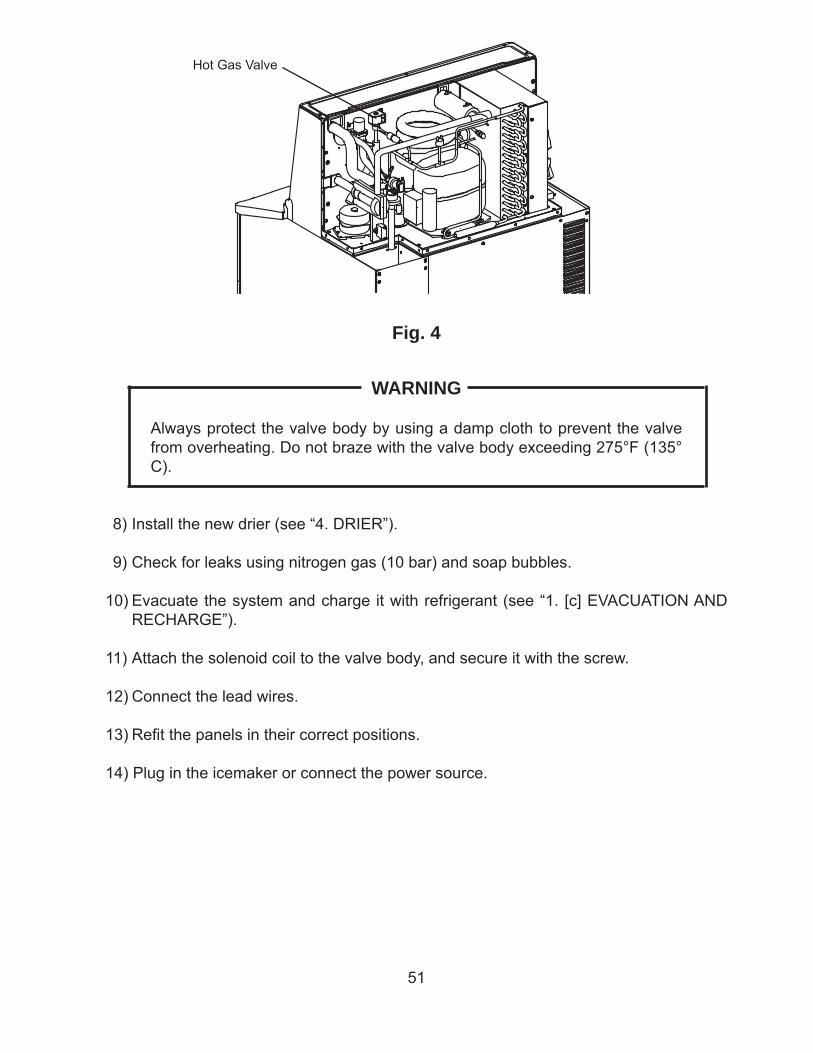
51
WARNING
Always protect the valve body by using a damp cloth to prevent the valve from overheating. Do not braze with the valve body exceeding 275°F (135°C).
8) Install the new drier (see “4. DRIER”).
9) Check for leaks using nitrogen gas (10 bar) and soap bubbles.
10) Evacuate the system and charge it with refrigerant (see “1. [c] EVACUATION AND RECHARGE”).
11) Attach the solenoid coil to the valve body, and secure it with the screw.
12) Connect the lead wires.
13) Refi t the panels in their correct positions.
14) Plug in the icemaker or connect the power source.
Fig. 4
Hot Gas Valve
52
6. EXPANSION VALVE
IMPORTANT
The water in the refrigeration circuit may exceed the capacity of the drier and freeze in the expansion valve. Always install a new drier every time the sealed refrigeration system is opened. Do not replace the drier until after all other repair or replacement has been made.
1) Unplug the icemaker or disconnect the power source.
2) Remove the top panel, rear panel and side panel (R).
3) Recover the refrigerant and store it in a proper container, if required by an applicable law (see “1. [b] REFRIGERANT RECOVERY”).
4) Remove the expansion valve using brazing equipment. Protect the evaporator and pipes from excessive heat with damp cloths or similar.
5) Remove the insulation hose from the expansion valve sensor (bulb) and remove the bulb.
6) Remove the drier using brazing equipment.
7) Braze in the new expansion valve. Protect the body of the valve from excessive heat, and use nitrogen at a pressure of 0.2 - 0.3 bar when brazing.
8) Install the new drier (see “4. DRIER”).
9) Check for leaks using nitrogen gas (10 bar) and soap bubbles.
10) Evacuate the system and charge it with refrigerant (see “1. [c] EVACUATION AND RECHARGE”).
11) Attach the bulb to the suction line in position. Be sure to secure it using a wire or clamp and replace the insulation.
12) Refi t the panels in their correct positions.
13) Plug in the icemaker or connect the power source.
WARNING
Always protect the valve body by using a damp cloth to prevent the valve from overheating. Do not braze with the valve body exceeding 239°F (115°C).
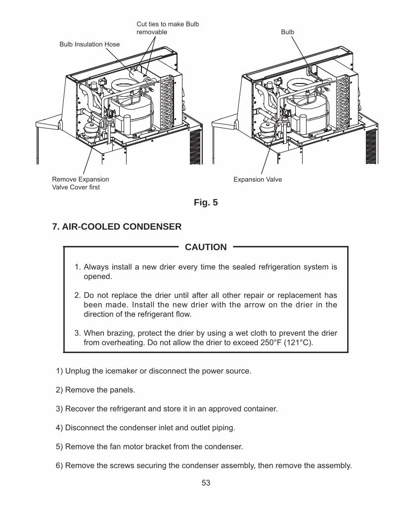
53
Fig. 5
Remove Expansion Valve Cover fi rst
Cut ties to make Bulb removable
Bulb Insulation Hose
Expansion Valve
Bulb
7. AIR-COOLED CONDENSER
CAUTION
1. Always install a new drier every time the sealed refrigeration system is opened.
2. Do not replace the drier until after all other repair or replacement has been made. Install the new drier with the arrow on the drier in the direction of the refrigerant fl ow.
3. When brazing, protect the drier by using a wet cloth to prevent the drier from overheating. Do not allow the drier to exceed 250°F (121°C).
1) Unplug the icemaker or disconnect the power source.
2) Remove the panels.
3) Recover the refrigerant and store it in an approved container.
4) Disconnect the condenser inlet and outlet piping.
5) Remove the fan motor bracket from the condenser.
6) Remove the screws securing the condenser assembly, then remove the assembly.
54
7) Install the new condenser, then attach the fan motor bracket.
8) Remove the drier, then place the new drier in position.
9) Braze all fi ttings while purging with nitrogen gas fl owing at a pressure of 3 to 4 PSIG.
10) Use an electronic leak detector or soap bubbles to check for leaks. Add a trace of refrigerant to the system (if using an electronic leak detector), and then raise the pressure using nitrogen gas (140 PSIG). DO NOT use R-404A as a mixture with pressurized air for leak testing.
11) Evacuate the system, and charge it with refrigerant. See the nameplate for the required refrigerant charge.
12) Replace the panels in their correct positions.
13) Plug in the icemaker or connect the power source.
8. WATER-COOLED CONDENSER
CAUTION
1. Always install a new drier every time the sealed refrigeration system is opened.
2. Do not replace the drier until after all other repair or replacement has been made. Install the new drier with the arrow on the drier in the direction of the refrigerant fl ow.
3. When brazing, protect the drier by using a wet cloth to prevent the drier from overheating. Do not allow the drier to exceed 250°F (121°C).
1) Unplug the icemaker or disconnect the power source.
2) Remove the panels.
3) Close the condenser water supply line shut-off valve. If connected to a closed loop water supply, also close the condenser return outlet shut-off valve.
4) Open the condenser water supply line drain valve. If connected to a closed loop water supply, also open the condenser return outlet drain valve.
5) Attach a compressed air or carbon dioxide supply to the condenser water supply line drain valve.
55
6) Open the water regulating valve by using a screwdriver to pry up on the spring retainer underneath the spring. While holding the valve open, blow out the condenser using the compressed air or carbon dioxide supply until water stops coming out.
7) Recover the refrigerant and store it in an approved container.
8) Disconnect the condenser water inlet and outlet piping and the refrigeration inlet and outlet piping at the condenser.
9) Remove the old condenser and install the new condenser.
10) Remove the drier, then place the new drier in position.
11) Braze all fi ttings while purging with nitrogen gas fl owing at a pressure of 3 to 4 PSIG.
12) Use an electronic leak detector or soap bubbles to check for leaks. Add a trace of refrigerant to the system (if using an electronic leak detector), and then raise the pressure using nitrogen gas (140 PSIG). DO NOT use R-404A as a mixture with pressurized air for leak testing.
13) Evacuate the system, and charge it with refrigerant. See the nameplate for the required refrigerant charge.
14) Close the drain valve(s). Open the condenser water supply line shut-off valve. If connected to a closed loop water supply, also open the condenser return outlet shut-off valve.
15) Check for water leaks.
16) Replace the panels in their correct positions.
17) Plug in the icemaker or connect the power source.
9. FAN MOTOR (AIR-COOLED MODEL)
1) Unplug the icemaker or disconnect the power source.
2) Remove the top panel, rear panel and side panel (L).
3) Disconnect the connector of the fan motor lead.
4) Remove the four screws securing the fan motor bracket and pull out the fan motor in the arrow direction. To prevent deformation, do not hit the fan on the condenser or other parts.
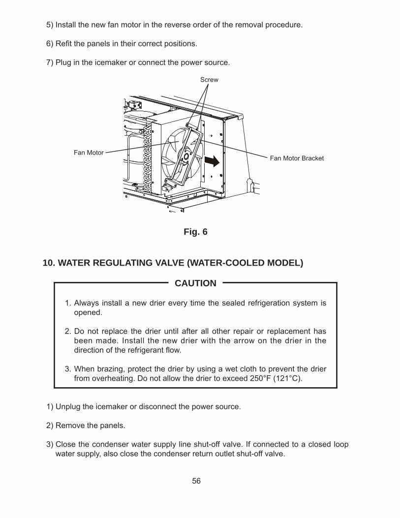
56
5) Install the new fan motor in the reverse order of the removal procedure.
6) Refi t the panels in their correct positions.
7) Plug in the icemaker or connect the power source.
Fig. 6
Fan Motor Bracket
Screw
Fan Motor
10. WATER REGULATING VALVE (WATER-COOLED MODEL)
CAUTION
1. Always install a new drier every time the sealed refrigeration system is opened.
2. Do not replace the drier until after all other repair or replacement has been made. Install the new drier with the arrow on the drier in the direction of the refrigerant fl ow.
3. When brazing, protect the drier by using a wet cloth to prevent the drier from overheating. Do not allow the drier to exceed 250°F (121°C).
1) Unplug the icemaker or disconnect the power source.
2) Remove the panels.
3) Close the condenser water supply line shut-off valve. If connected to a closed loop water supply, also close the condenser return outlet shut-off valve.
57
4) Open the condenser water supply line drain valve. If connected to a closed loop water supply, also open the condenser return outlet drain valve.
5) Attach a compressed air or carbon dioxide supply to the condenser water supply line drain valve.
6) Open the water regulating valve by using a screwdriver to pry up on the spring retainer underneath the spring. While holding the valve open, blow out the condenser using the compressed air or carbon dioxide supply until water stops coming out.
7) Recover the refrigerant and store it in an approved container.
8) Disconnect the capillary tube at the condenser outlet.
9) Disconnect the fl are-connections of the valve.
10) Remove the screws and the valve from the bracket.
11) Install the new valve.
12) Remove the drier, then place the new drier in position.
13) Braze all fi ttings while purging with nitrogen gas fl owing at a pressure of 3 to 4 PSIG.
14) Use an electronic leak detector or soap bubbles to check for leaks. Add a trace of refrigerant to the system (if using an electronic leak detector), and then raise the pressure using nitrogen gas (140 PSIG). DO NOT use R-404A as a mixture with pressurized air for leak testing.
15) Evacuate the system, and charge it with refrigerant. See the nameplate for the required refrigerant charge.
16) Connect the fl are-connections.
17) Close the drain valve(s). Open the condenser water supply line shut-off valve. If connected to a closed loop water supply, also open the condenser return outlet shut-off valve.
18) Check for water leaks.
19) Replace the panels in their correct positions.
20) Plug in the icemaker or connect the power source.
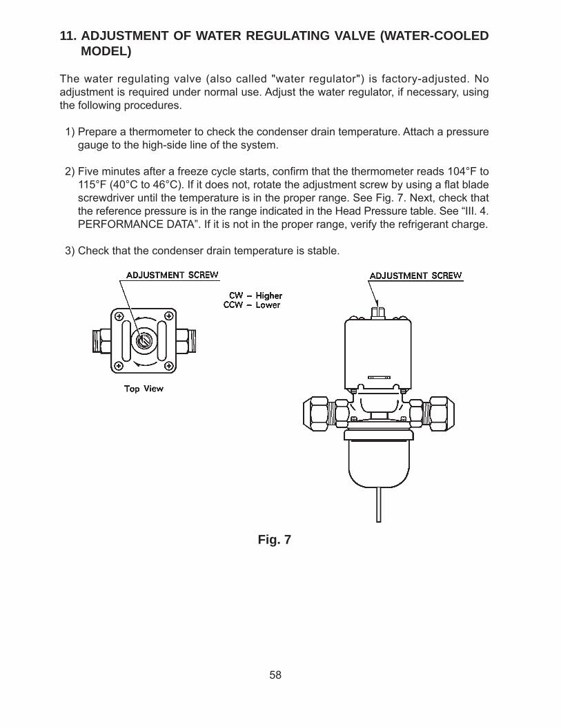
58
11. ADJUSTMENT OF WATER REGULATING VALVE (WATER-COOLED MODEL)
The water regulating valve (also called "water regulator") is factory-adjusted. No adjustment is required under normal use. Adjust the water regulator, if necessary, using the following procedures.
1) Prepare a thermometer to check the condenser drain temperature. Attach a pressure gauge to the high-side line of the system.
2) Five minutes after a freeze cycle starts, confi rm that the thermometer reads 104°F to 115°F (40°C to 46°C). If it does not, rotate the adjustment screw by using a fl at blade screwdriver until the temperature is in the proper range. See Fig. 7. Next, check that the reference pressure is in the range indicated in the Head Pressure table. See “III. 4. PERFORMANCE DATA”. If it is not in the proper range, verify the refrigerant charge.
3) Check that the condenser drain temperature is stable.
Fig. 7
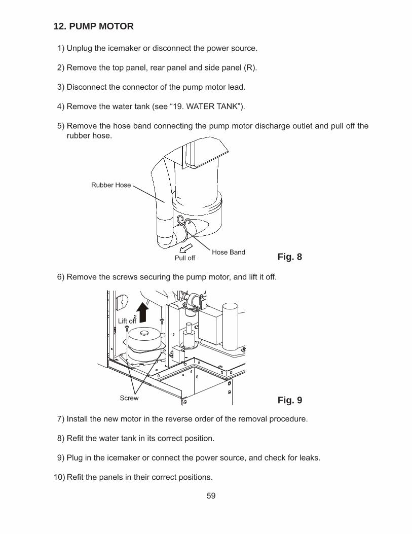
59
12. PUMP MOTOR
1) Unplug the icemaker or disconnect the power source.
2) Remove the top panel, rear panel and side panel (R).
3) Disconnect the connector of the pump motor lead.
4) Remove the water tank (see “19. WATER TANK”).
5) Remove the hose band connecting the pump motor discharge outlet and pull off the rubber hose.
Fig. 8
6) Remove the screws securing the pump motor, and lift it off.
Hose Band
Rubber Hose
7) Install the new motor in the reverse order of the removal procedure.
8) Refi t the water tank in its correct position.
9) Plug in the icemaker or connect the power source, and check for leaks.
10) Refi t the panels in their correct positions.
Fig. 9Screw
Lift off
Pull off
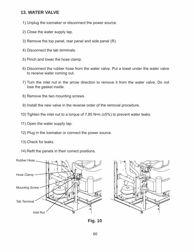
60
13. WATER VALVE
1) Unplug the icemaker or disconnect the power source.
2) Close the water supply tap.
3) Remove the top panel, rear panel and side panel (R).
4) Disconnect the tab terminals.
5) Pinch and lower the hose clamp.
6) Disconnect the rubber hose from the water valve. Put a towel under the water valve to receive water coming out.
7) Turn the inlet nut in the arrow direction to remove it from the water valve. Do not lose the gasket inside.
8) Remove the two mounting screws.
9) Install the new valve in the reverse order of the removal procedure.
10) Tighten the inlet nut to a torque of 7.85 N•m (±5%) to prevent water leaks.
11) Open the water supply tap.
12) Plug in the icemaker or connect the power source.
13) Check for leaks.
14) Refi t the panels in their correct positions.
Fig. 10
Tab Terminal
Hose Clamp
Inlet Nut
Mounting Screw
Rubber Hose
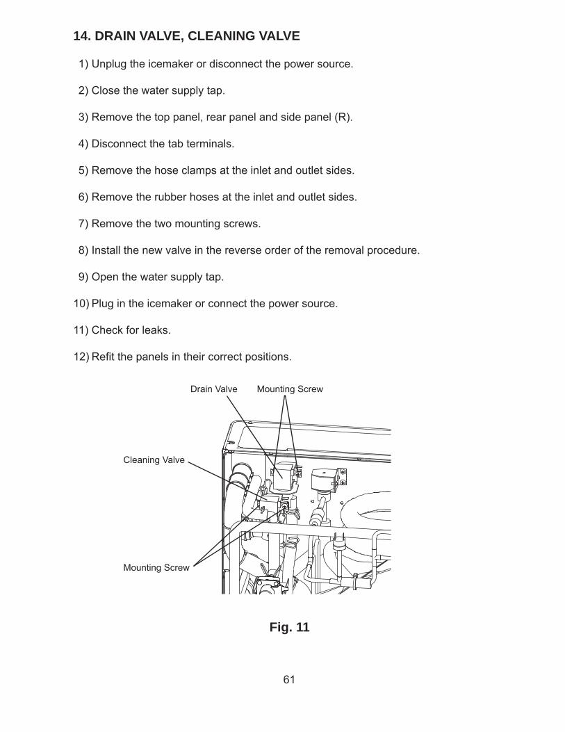
61
14. DRAIN VALVE, CLEANING VALVE
1) Unplug the icemaker or disconnect the power source.
2) Close the water supply tap.
3) Remove the top panel, rear panel and side panel (R).
4) Disconnect the tab terminals.
5) Remove the hose clamps at the inlet and outlet sides.
6) Remove the rubber hoses at the inlet and outlet sides.
7) Remove the two mounting screws.
8) Install the new valve in the reverse order of the removal procedure.
9) Open the water supply tap.
10) Plug in the icemaker or connect the power source.
11) Check for leaks.
12) Refi t the panels in their correct positions.
Fig. 11
Drain Valve Mounting Screw
Mounting Screw
Cleaning Valve
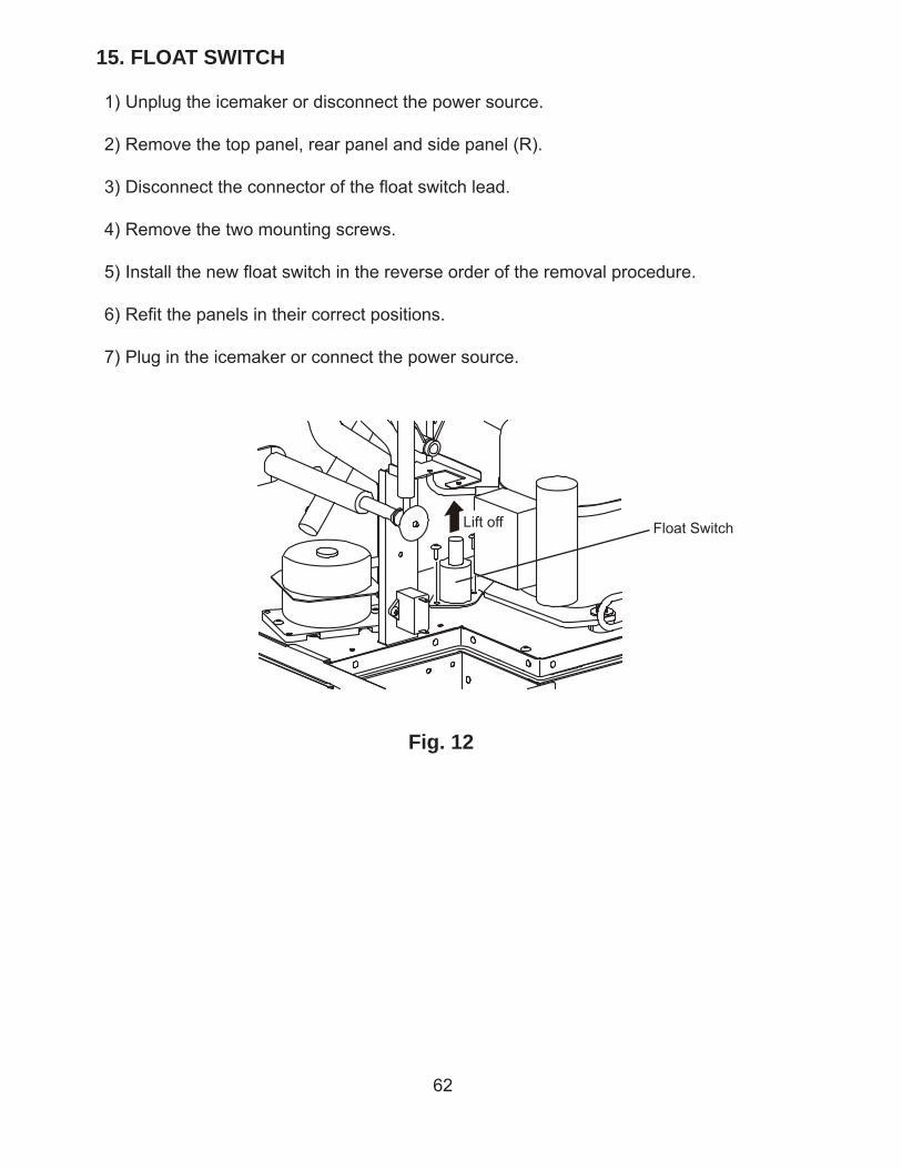
62
15. FLOAT SWITCH
1) Unplug the icemaker or disconnect the power source.
2) Remove the top panel, rear panel and side panel (R).
3) Disconnect the connector of the fl oat switch lead.
4) Remove the two mounting screws.
5) Install the new fl oat switch in the reverse order of the removal procedure.
6) Refi t the panels in their correct positions.
7) Plug in the icemaker or connect the power source.
Fig. 12
Float SwitchLift off
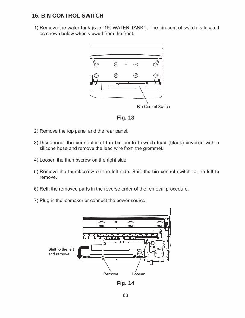
63
16. BIN CONTROL SWITCH
1) Remove the water tank (see “19. WATER TANK”). The bin control switch is located as shown below when viewed from the front.
Fig. 13
Bin Control Switch
2) Remove the top panel and the rear panel.
3) Disconnect the connector of the bin control switch lead (black) covered with a silicone hose and remove the lead wire from the grommet.
4) Loosen the thumbscrew on the right side.
5) Remove the thumbscrew on the left side. Shift the bin control switch to the left to remove.
6) Refi t the removed parts in the reverse order of the removal procedure.
7) Plug in the icemaker or connect the power source.
Fig. 14Remove Loosen
Shift to the left and remove
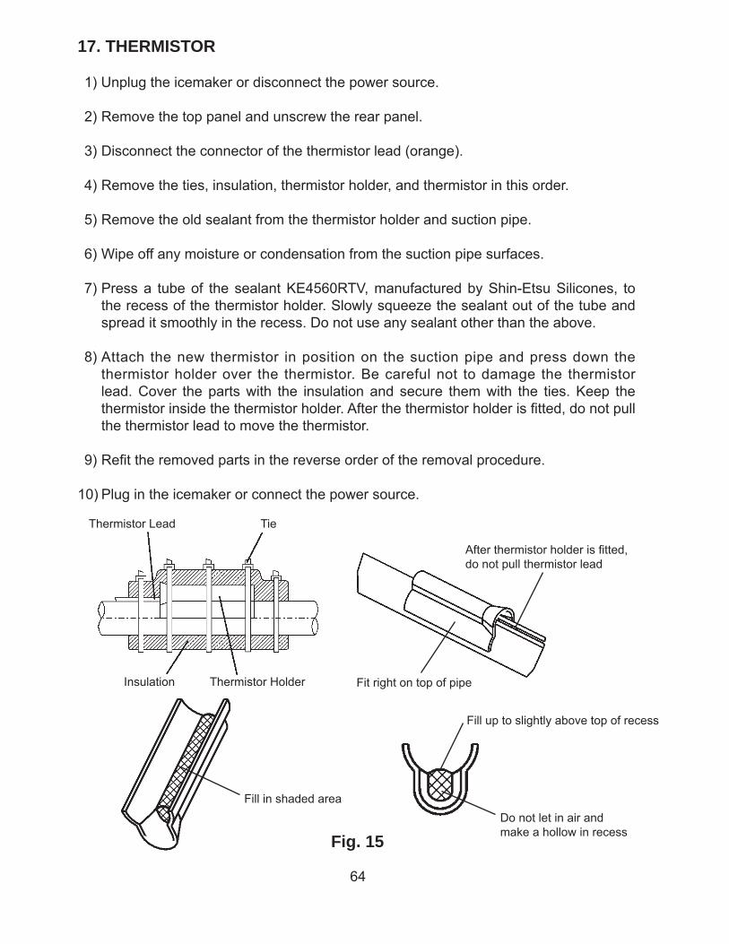
64
17. THERMISTOR
1) Unplug the icemaker or disconnect the power source.
2) Remove the top panel and unscrew the rear panel.
3) Disconnect the connector of the thermistor lead (orange).
4) Remove the ties, insulation, thermistor holder, and thermistor in this order.
5) Remove the old sealant from the thermistor holder and suction pipe.
6) Wipe off any moisture or condensation from the suction pipe surfaces.
7) Press a tube of the sealant KE4560RTV, manufactured by Shin-Etsu Silicones, to the recess of the thermistor holder. Slowly squeeze the sealant out of the tube and spread it smoothly in the recess. Do not use any sealant other than the above.
8) Attach the new thermistor in position on the suction pipe and press down the thermistor holder over the thermistor. Be careful not to damage the thermistor lead. Cover the parts with the insulation and secure them with the ties. Keep the thermistor inside the thermistor holder. After the thermistor holder is fi tted, do not pull the thermistor lead to move the thermistor.
9) Refi t the removed parts in the reverse order of the removal procedure.
10) Plug in the icemaker or connect the power source.
Fig. 15
Thermistor Lead Tie
Insulation Thermistor Holder Fit right on top of pipe
After thermistor holder is fi tted, do not pull thermistor lead
Fill in shaded area
Fill up to slightly above top of recess
Do not let in air and make a hollow in recess
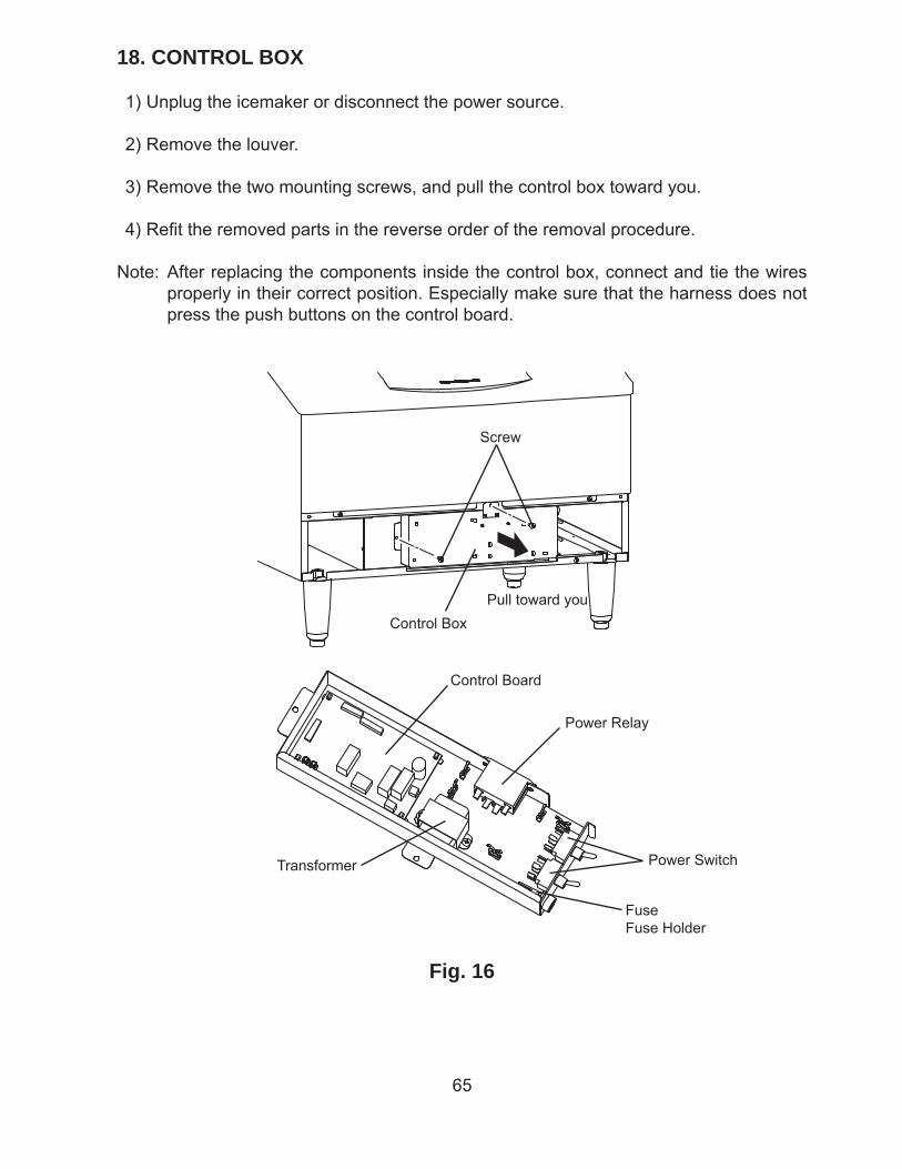
65
18. CONTROL BOX
1) Unplug the icemaker or disconnect the power source.
2) Remove the louver.
3) Remove the two mounting screws, and pull the control box toward you.
4) Refi t the removed parts in the reverse order of the removal procedure.
Note: After replacing the components inside the control box, connect and tie the wires properly in their correct position. Especially make sure that the harness does not press the push buttons on the control board.
Fig. 16
Screw
Control Box
Power Relay
Transformer
Control Board
Power Switch
FuseFuse Holder
Pull toward you
66
[a] POWER SWITCH
1) Disconnect the tab terminals and remove the nut securing the power switch.
2) Install the new switch in the reverse order of the removal procedure.
3) To prevent miswiring, check the terminal numbers and lead wire colors with the wiring label.
[b] FUSE
1) Use a phillips head screwdriver to remove the fuse holder cap and take out the fuse.
2) Install the new fuse in the reverse order of the removal procedure.
[c] FUSE HOLDER
1) Disconnect the tab terminal and remove the nut securing the fuse holder.
2) Install the new fuse holder in the reverse order of the removal procedure.
[d] CONTROL BOARD
1) Disconnect all the connectors.
2) Pull the tab to release the control board.
3) Lift off the control board.
4) To refi t the control board, fi t its four corner holes on the positioning lugs inside the control box and secure the control board with the tab.
5) Check the dip switch for proper setting.
6) When reconnecting the connectors, do not push them too hard. The control board may be damaged.
[e] POWER RELAY
1) Disconnect the tab terminals, remove the mounting screw, and lift off the power relay from the fi t at the bottom.
2) Install the new relay in the reverse order of the removal procedure.
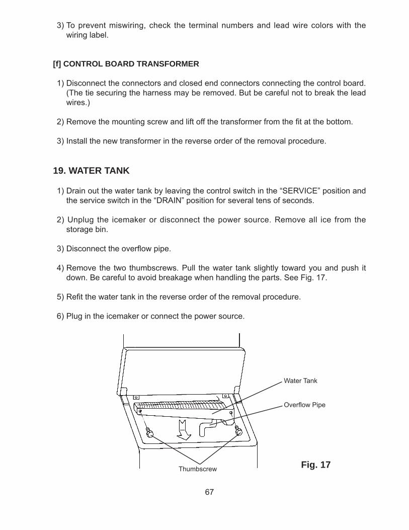
67
3) To prevent miswiring, check the terminal numbers and lead wire colors with the wiring label.
[f] CONTROL BOARD TRANSFORMER
1) Disconnect the connectors and closed end connectors connecting the control board. (The tie securing the harness may be removed. But be careful not to break the lead wires.)
2) Remove the mounting screw and lift off the transformer from the fi t at the bottom.
3) Install the new transformer in the reverse order of the removal procedure.
19. WATER TANK
1) Drain out the water tank by leaving the control switch in the “SERVICE” position and the service switch in the “DRAIN” position for several tens of seconds.
2) Unplug the icemaker or disconnect the power source. Remove all ice from the storage bin.
3) Disconnect the overfl ow pipe.
4) Remove the two thumbscrews. Pull the water tank slightly toward you and push it down. Be careful to avoid breakage when handling the parts. See Fig. 17.
5) Refi t the water tank in the reverse order of the removal procedure.
6) Plug in the icemaker or connect the power source.
Fig. 17Thumbscrew
Water Tank
Overfl ow Pipe
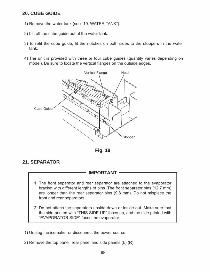
68
20. CUBE GUIDE
1) Remove the water tank (see “19. WATER TANK”).
2) Lift off the cube guide out of the water tank.
3) To refi t the cube guide, fi t the notches on both sides to the stoppers in the water tank.
4) The unit is provided with three or four cube guides (quantity varies depending on model). Be sure to locate the vertical fl anges on the outside edges.
Fig. 18
Cube Guide
Vertical Flange Notch
Stopper
21. SEPARATOR
IMPORTANT
1. The front separator and rear separator are attached to the evaporator bracket with different lengths of pins. The front separator pins (12.7 mm) are longer than the rear separator pins (9.8 mm). Do not misplace the front and rear separators.
2. Do not attach the separators upside down or inside out. Make sure that the side printed with “THIS SIDE UP” faces up, and the side printed with “EVAPORATOR SIDE” faces the evaporator.
1) Unplug the icemaker or disconnect the power source.
2) Remove the top panel, rear panel and side panels (L) (R).
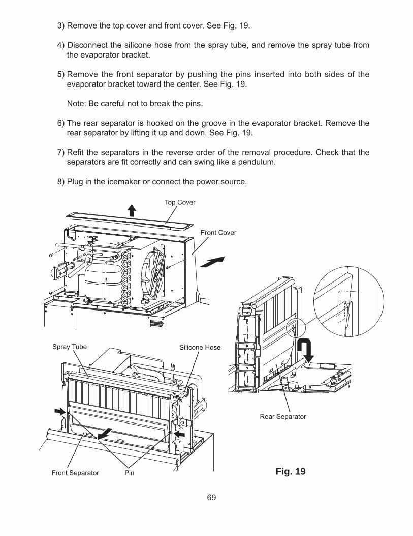
69
Fig. 19
Spray Tube
Front Separator Pin
3) Remove the top cover and front cover. See Fig. 19.
4) Disconnect the silicone hose from the spray tube, and remove the spray tube from the evaporator bracket.
5) Remove the front separator by pushing the pins inserted into both sides of the evaporator bracket toward the center. See Fig. 19.
Note: Be careful not to break the pins.
6) The rear separator is hooked on the groove in the evaporator bracket. Remove the rear separator by lifting it up and down. See Fig. 19.
7) Refi t the separators in the reverse order of the removal procedure. Check that the separators are fi t correctly and can swing like a pendulum.
8) Plug in the icemaker or connect the power source.
Silicone Hose
Front Cover
Top Cover
Rear Separator
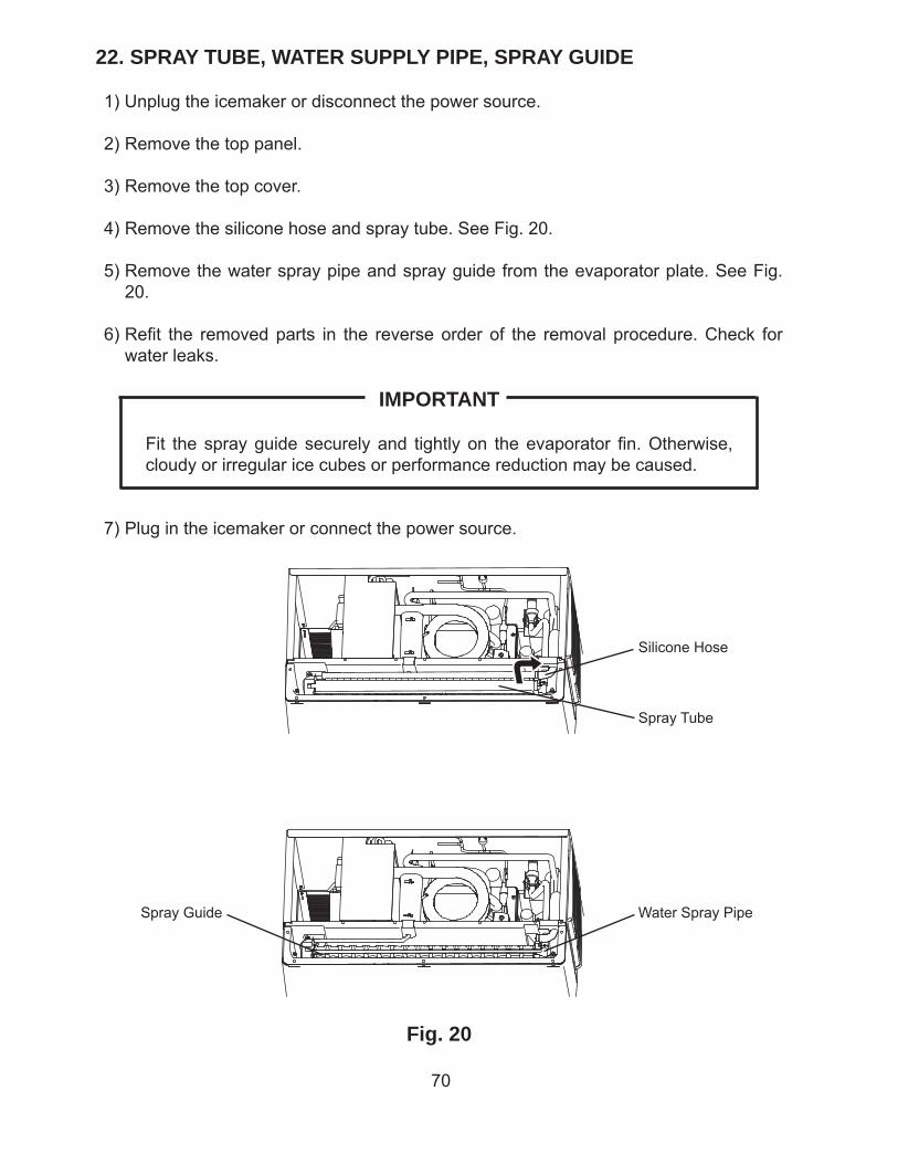
70
22. SPRAY TUBE, WATER SUPPLY PIPE, SPRAY GUIDE
1) Unplug the icemaker or disconnect the power source.
2) Remove the top panel.
3) Remove the top cover.
4) Remove the silicone hose and spray tube. See Fig. 20.
5) Remove the water spray pipe and spray guide from the evaporator plate. See Fig. 20.
6) Refi t the removed parts in the reverse order of the removal procedure. Check for water leaks.
IMPORTANT
Fit the spray guide securely and tightly on the evaporator fi n. Otherwise, cloudy or irregular ice cubes or performance reduction may be caused.
7) Plug in the icemaker or connect the power source.
Fig. 20
Silicone Hose
Spray Tube
Spray Guide Water Spray Pipe
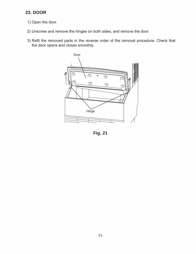
71
23. DOOR
1) Open the door.
2) Unscrew and remove the hinges on both sides, and remove the door.
3) Refi t the removed parts in the reverse order of the removal procedure. Check that the door opens and closes smoothly.
Fig. 21
Door
Hinge
72
VI. CLEANING AND MAINTENANCE INSTRUCTIONS
IMPORTANT
Ensure all components, fasteners and screws are securely in place after any maintenance or cleaning is done to the equipment.
1. CLEANING
WARNING
1. Hoshizaki recommends cleaning this unit at least once a year. More frequent cleaning, however, may be required in some existing water conditions.
2. To prevent injury to individuals and damage to the icemaker, do not use ammonia type cleaners.
3. Always wear liquid-proof gloves to prevent the cleaning and sanitizing solutions from coming into contact with skin.
4. For safety and maximum effectiveness, use cleaning and sanitizing solutions immediately after dilution.
[a] CLEANING PROCEDURE
1) Dilute 5 fl . oz. (148 ml) of recommended cleaner Hoshizaki “Scale Away” or “LIME-A-WAY” (Economics Laboratory, Inc.) with 1 gal. (3.8 lit.) of water.
2) Remove the louver. Open the door and remove all ice from the evaporator and the storage bin.
Note: To remove cubes on the evaporator, move the control switch on the control box to the “OFF” position and move it back to the “ICE” position after 3 minutes. The defrost cycle starts and the cubes will be removed from the evaporator.
3) Move the control switch to the “OFF” position.
4) Move the control switch to the “SERVICE” position and the service switch to the “DRAIN” position.
5) After 2 minutes, move the control switch to the “OFF” position.
73
6) Pour the cleaning solution into the water tank. Move the control switch to the “SERVICE” position and the service switch to the “WASH” position. Close the door.
7) After 30 minutes, move the control switch to the “OFF” position.
8) Same as step 4.
9) Move the control switch to the “ICE” position to fi ll the water tank with water.
10) After 3 minutes, move the control switch to the “SERVICE” position and the service switch to the “WASH” position.
11) After 5 minutes, move the control switch to the “OFF” position.
12) Same as step 4.
13) Repeat steps 9 through 12 three more times to rinse thoroughly.
14) Disconnect the overflow pipe. Next, remove the water tank by removing the two thumbscrews and pulling the tank towards you slightly and pushing it down. Be careful to avoid breakage when handling the parts. See Fig. 17.
15) Pull the cube guides (quantity varies depending on model) upward to remove them from the water tank. They are snapped in place. See Fig. 18.
16) Same as step 1.
17) Wash the bin control switch, water tank, fl oat switch, cube guide and overfl ow pipe by using a nylon scouring pad, brushes and the cleaning solution. In addition to the removed parts, also wash the bin liner and bracket (L) (R) with the solution.
18) Discard the cleaning solution and rinse the parts thoroughly with water.
[b] SANITIZING PROCEDURE - Following Cleaning Procedure
1) Dilute approximately 0.5 fl. oz. (15 ml) of a 5.25% sodium hypochlorite solution (chlorine bleach) with 1 gal. (3.8 lit.) of warm water. Using a chlorine test strip or other method, confi rm that you have a concentration of about 200 ppm.
2) Soak the removed parts from step 17 above in a clean container containing the sanitizing solution. After allowing the parts to soak for 10 minutes, wash them with the solution. Also wash the bin liner, bracket (L) (R) with the solution.
3) Discard the sanitizing solution and rinse the parts thoroughly with water.
4) Replace the removed parts in their correct positions in the reverse order of which
74
they were removed.
5) Same as step 1.
6) Pour the sanitizing solution into the water tank, and allow the sanitizer to sit for 10 minutes.
7) Move the control switch to the “SERVICE” position and the service switch to the “WASH” position.
8) After 15 minutes, move the control switch to the “OFF” position.
9) Move the control switch to the “SERVICE” position and the service switch to the “DRAIN” position.
10) After 2 minutes, move the control switch to the “OFF” position.
11) Repeat steps 5 through 10 one time. Repeat steps 9 through 12 in the Cleaning Procedure three times to rinse thoroughly.
12) Flush the storage bin with water.
13) Move the control switch to the “ICE” position, and start the automatic icemaking process.
14) Close the door. Replace the louver in its correct position.
2. MAINTENANCE
[a] EXTERIOR PANELS
To prevent corrosion, wipe the exterior occasionally with a clean and soft cloth. Use a damp cloth containing a neutral cleaner to wipe off all oil or dirt build up.
[b] STORAGE BIN AND SCOOP
* Wash your hands before removing ice. Use the plastic scoop provided (Accessory).
* The storage bin is for ice use only. Do not store anything else in the bin.
* Keep the scoop clean. Clean it by using a neutral cleaner and rinse thoroughly.
* Clean the bin liner by using a neutral cleaner. Rinse thoroughly after cleaning.
75
[c] AIR FILTER (AIR-COOLED MODEL)
The plastic mesh air fi lter removes dirt or dust from the air, and keeps the condenser from getting clogged. As the filter gets clogged, the icemaker’s performance will be reduced. Check the fi lter at least twice a month. When it is clogged, use warm water and a neutral cleaner to wash the fi lter.
[d] CONDENSER (AIR-COOLED MODEL)
Check the condenser once a year, and clean if required by using a brush or vacuum cleaner. More frequent cleaning may be required depending on the location of the icemaker.
3. PREPARING THE ICEMAKER FOR LONG STORAGE
IMPORTANT
When shutting off the icemaker for an extended time, drain out all water from the water lines and remove the ice from the storage bin. The storage bin should be cleaned and dried. Drain the icemaker using air or carbon dioxide to prevent damage to the water supply lines at sub-freezing temperatures. Shut off the icemaker until the proper ambient temperature is resumed.
When the icemaker is not used for two or three days, it is sufficient to only move the control switch to the “OFF” position, unless the icemaker will be at sub-freezing temperatures.
[a] Remove the water from the potable water supply line:
1) Remove the louver if it has not already been removed.
2) Move the control switch on the control box to the “OFF” position. See Fig. 3.
3) Wait 3 minutes.
4) Close the potable water supply line stop valve. See Fig. 22.
5) Remove the inlet hose.
[b] Drain the potable Water Tank:
1) Move the control switch to the “SERVICE” position and the service switch to the
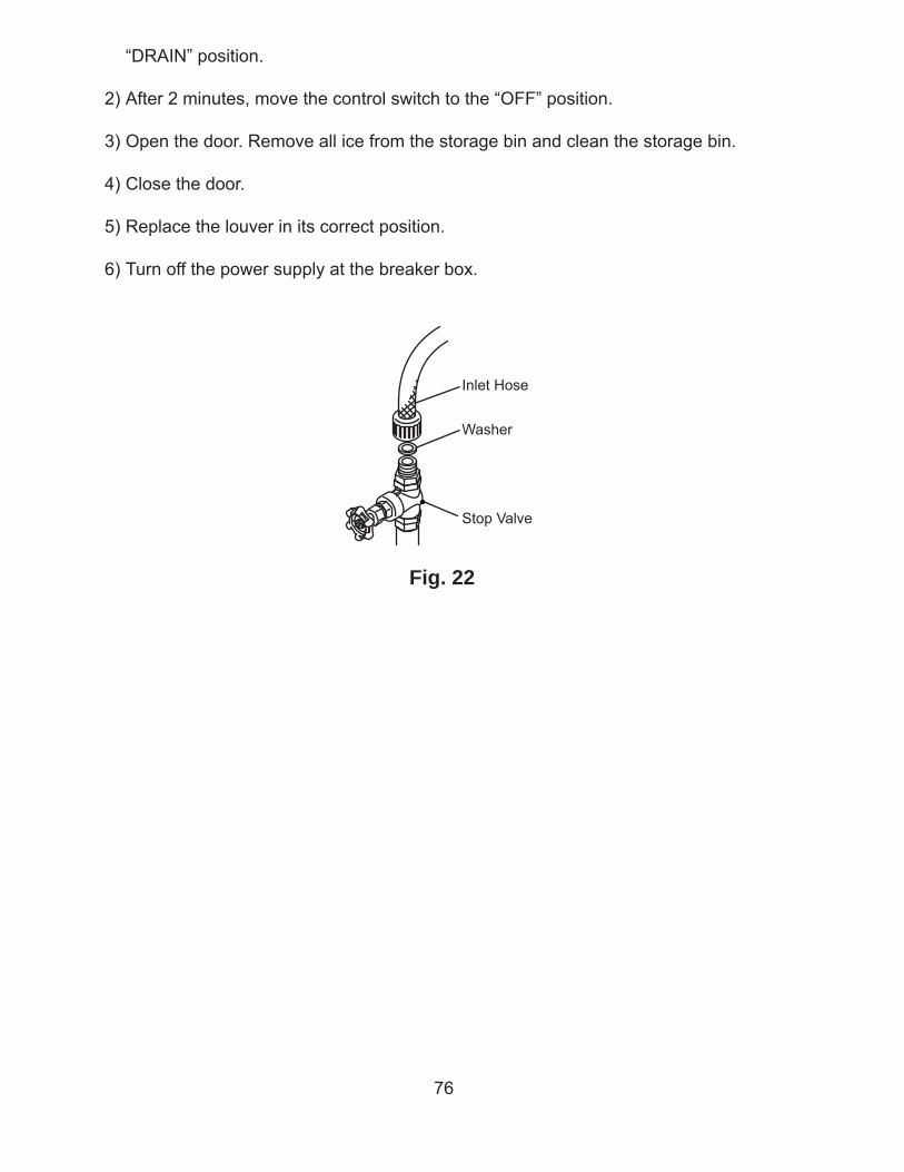
76
“DRAIN” position.
2) After 2 minutes, move the control switch to the “OFF” position.
3) Open the door. Remove all ice from the storage bin and clean the storage bin.
4) Close the door.
5) Replace the louver in its correct position.
6) Turn off the power supply at the breaker box.
Fig. 22
Inlet Hose
Washer
Stop Valve