Hornsea Project Four: Environmental Statement (ES)
55
Prepared Hornsea Four, July 2021 Checked Sarah Randal, July 2021 Accepted Francesca De Vita, July 2021 Approved Julian Carolan, July 2021 Doc. No: A4.6.1 Version: A Hornsea Project Four: Environmental Statement (ES) PINS Document Reference: A4.6.1 APFP Regulation: 5(2)(a) Volume A4, Annex 6.1: Compensation Project Description
Transcript of Hornsea Project Four: Environmental Statement (ES)
Prepared Hornsea Four, July 2021
Checked Sarah Randal, July 2021
Accepted Francesca De Vita, July 2021
Approved Julian Carolan, July 2021
Doc. No: A4.6.1
Version: A
Hornsea Project Four: Environmental Statement (ES) PINS Document Reference: A4.6.1 APFP Regulation: 5(2)(a)
Volume A4, Annex 6.1: Compensation Project Description
Page 2/55 Doc. No: A4.6.1
Ver. no. A
Table of Contents
1 Introduction........................................................................................................................................................... 8
1.1 Project Background ............................................................................................................................. 8
1.2 The Derogation Provisions of the Habitats Regulations............................................................ 9
1.3 Development of Compensation Measures ................................................................................. 10
1.4 Compensation measures ................................................................................................................ 11
1.5 Programme ......................................................................................................................................... 14
1.6 Decommissioning .............................................................................................................................. 14
2 Offshore Artificial Nesting Platforms .......................................................................................................... 14
2.1 Introduction and Background ........................................................................................................ 14
2.2 Offshore Platform Design ............................................................................................................... 16
2.3 Description of topside design ......................................................................................................... 17
2.4 Description of foundation design .................................................................................................. 18
2.5 Location ............................................................................................................................................... 18
2.6 Construction ....................................................................................................................................... 19
2.7 Operation and Maintenance .......................................................................................................... 25
2.8 Decommissioning .............................................................................................................................. 27
2.9 Monitoring and Adaptive Management ...................................................................................... 27
2.10 Summary of Offshore Artificial Nesting Structures .................................................................. 27
3 Onshore Artificial Nesting Platform ............................................................................................................ 28
3.1 Introduction and Background ........................................................................................................ 28
3.2 Design Principles ................................................................................................................................ 28
3.3 Indicative Maximum Parameters................................................................................................... 29
3.4 Decommissioning .............................................................................................................................. 31
3.5 Location ............................................................................................................................................... 31
3.6 Summary of Onshore Artificial Nesting Structures................................................................... 32
4 Bycatch mitigation ........................................................................................................................................... 33
4.1 Introduction and Background ........................................................................................................ 33
4.2 Bycatch Mitigation Technology .................................................................................................... 33
4.3 Fishery Types ...................................................................................................................................... 36
4.4 Location ............................................................................................................................................... 36
4.5 Implementation, operation, and monitoring.............................................................................. 40
4.6 Other projects and trials ................................................................................................................. 40

Page 3/55 Doc. No: A4.6.1
Ver. no. A
4.7 Summary of Bycatch Compensation Measure .......................................................................... 40
5 Predator Eradication ....................................................................................................................................... 41
5.1 Introduction and Background ........................................................................................................ 41
5.2 Proposals for Hornsea Four ............................................................................................................ 42
5.3 Location ............................................................................................................................................... 42
5.4 Operation, implementation, and monitoring ............................................................................. 43
5.5 Summary of Predator Eradication Compensation Measure .................................................. 43
6 Fish Habitat Enhancement ............................................................................................................................. 44
6.1 Introduction and Background ........................................................................................................ 44
6.2 The importance of seagrass ........................................................................................................... 45
6.3 Seagrass Restoration Projects ....................................................................................................... 46
6.4 Seagrass Restoration Techniques ................................................................................................. 47
6.5 Location ............................................................................................................................................... 48
6.6 Implementation, operation, and monitoring.............................................................................. 48
6.7 Summary of Fish Habitat Enhancement Compensation Measure ........................................ 50
7 References ......................................................................................................................................................... 51
7.1 Introduction ........................................................................................................................................ 51
7.2 Kittiwake nesting .............................................................................................................................. 51
7.3 Predator eradication ........................................................................................................................ 52
7.4 Bycatch ................................................................................................................................................ 54
7.5 Seagrass .............................................................................................................................................. 54
List of Tables
Table 1: Compensation Measures, sub-options, locations, location ID and species being
compensated. ............................................................................................................................................................ 12 Table 2 : Maximum design parameters for existing topside structure to be repurposed for offshore
nesting. ........................................................................................................................................................................ 16 Table 3: Maximum design parameters for new offshore nesting platform. .............................................. 17 Table 4: Foundation installation summary for new structures. .................................................................... 21 Table 5: Indicative Maximum design* parameters for the new offshore nesting platform
foundations. ............................................................................................................................................................... 24 Table 6: Maximum design parameters for general offshore operation and maintenance activities.. 26 Table 7: Offshore operation and maintenance activities. ............................................................................. 26 Table 8: Indicative maximum design parameters for the onshore nesting platforms. ........................... 29 Table 9: Onshore nesting structure design principles. .................................................................................... 31

Page 4/55 Doc. No: A4.6.1
Ver. no. A
List of Figures
Figure 1: Compensation Search Areas ................................................................................................................ 13 Figure 2: Kittiwake nesting on an Oil and Gas Platform in the Southern North Sea. .............................. 15 Figure 3: Foundation types (indicative only). ..................................................................................................... 18 Figure 4: An above water deterrent .................................................................................................................... 34 Figure 5: Looming Eye Buoy ................................................................................................................................... 35 Figure 6: A commercially available net light ..................................................................................................... 36 Figure 7: South Coast Bycatch Mitigation Search Area. ................................................................................. 38 Figure 8: Thames Estuary Bycatch Mitigation Search Area. .......................................................................... 39 Figure 9: Seagrass providing shelter for fish (copyright R.Unsworth). ......................................................... 44
Page 5/55 Doc. No: A4.6.1
Ver. no. A
Glossary
Term Definition
Commitment Hornsea Four, throughout the pre-Application consultation process, has produced a
Commitments Register which forms a quick reference guide to commitments the
project has made. Commitment is a term used interchangeably with mitigation and
enhancement measures. The purpose of Commitments is to reduce and/or eliminate
Likely Significant Effects (LSEs), in EIA terms. Primary (Design) or Tertiary (Inherent)
are both embedded within the assessment Secondary commitments are
incorporated to reduce LSE to environmentally acceptable levels following initial
assessment i.e. so that residual effects are acceptable.
Compensation Measures
The measures that have been developed by the Applicant pursuant to the HRA
Derogation Provisions “without prejudice” to the Applicants position of no Adverse
Effect on Site Integrity at the Flamborough and Filey Coast in respect of the
qualifying features. The Compensation Measures are:
[offshore and onshore nesting; predator eradication; bycatch and fish habitat
enhancement measures]. Each a Compensation Measure and together
Compensation Measures.
Cumulative effects The combined effect of Hornsea Four in combination with the effects from a number
of different projects, on the same single receptor/resource. Cumulative impacts are
those that result from changes caused by other past, present or reasonably
foreseeable actions together with Hornsea Project Four.
Design Envelope A description of the range of possible elements that make up the Hornsea Project
Four design options under consideration, as set out in detail in the project description
and this Compensation Project Description. This envelope is used to define Hornsea
Project Four for Environmental Impact Assessment (EIA) purposes when the exact
engineering parameters are not yet known. This is also often referred to as the
“Rochdale Envelope” approach.
Development Consent Order
(DCO)
An order made under the Planning Act 2008 granting development consent for one
or more Nationally Significant Infrastructure Projects (NSIP).
Environmental Impact
Assessment (EIA)
A statutory process by which certain planned projects must be assessed before a
formal decision to proceed can be made. It involves the collection and consideration
of environmental information, which fulfils the assessment requirements of the EIA
Directive and EIA Regulations, including the publication of an Environmental
Statement (ES).
Hornsea Project Four
Offshore Wind Farm
The term covers all elements of the project (i.e. both the offshore and onshore).
Hornsea Four infrastructure will include offshore generating stations (wind turbines),
electrical export cables to landfall, connection to the electricity transmission
network. Hereafter referred to as Hornsea Four.
Landfall The generic term applied to the entire landfall area between Mean Low Water
Spring (MLWS) tide and the Transition Joint Bay (TJB) inclusive of all construction
Page 6/55 Doc. No: A4.6.1
Ver. no. A
works, including the offshore and onshore ECC, intertidal working area and landfall
compound. Where the offshore cables come ashore east of Fraisthorpe.
Maximum Design Scenario
(MDS)
The maximum design parameters of each Hornsea Four asset (both on and offshore)
considered to be a worst case for any given assessment.
Mitigation A term used interchangeably with Commitment(s) by Hornsea Four. Mitigation
measures (Commitments) are embedded within the assessment at the relevant
point in the EIA (e.g. at Scoping, or PEIR or ES).
Order Limits The limits within which Hornsea Project Four (the ‘authorised project) may be carried
out.
Orsted Hornsea Project Four
Ltd.
The Applicant for the proposed Hornsea Project Four Offshore Wind Farm
Development Consent Order (DCO).
Planning Inspectorate (PINS) The agency responsible for operating the planning process for Nationally Significant
Infrastructure Projects (NSIPs).
Page 7/55 Doc. No: A4.6.1
Ver. no. A
Acronyms
Term Definition
DCO Development Consent Order
EIA Environmental Impact Assessment
ES Environmental Statement
HRA Habitats Regulations Assessment
MDS Maximum Design Scenario
MLWS Mean Low Water Springs
MMO Marine Management Organisation
PEIR Preliminary Environmental Information Report
PINS The Planning Inspectorate
PSA Particle Size Analysis
SAC Special Area of Conservation
SPA Special Protection Area
SSS Side-Scan Sonar
TCE The Crown Estate
UKHO UK Hydrographic Office
Units
Unit Definition
dB Decibel (sound pressure)
Hz Hertz (frequency)
Page 8/55 Doc. No: A4.6.1
Ver. no. A
1 Introduction
1.1 Project Background
1.1.1.1 Orsted Hornsea Project Four Limited (the ‘Applicant’) is proposing to develop Hornsea
Project Four Offshore Wind Farm (‘Hornsea Four’).
1.1.1.2 The purpose of this Environmental Impact Assessment (EIA) Project Description Annex is to
provide a description of the proposed Compensation Measures the Applicant may be
required to deliver to compensate for potential impacts upon certain seabird species at the
Flamborough and Filey Coast Special Protection Area (FFC SPA), located on the East Coast
of England. The Compensation Measures are proposed “without prejudice” to the
Applicant’s conclusion of No Adverse Effect on Integrity (AEoI) upon the seabird species
(kittiwake, gannet, guillemot and razorbill) in the Report to Inform the Appropriate
Assessment (RIAA).
1.1.1.3 The Hornsea Four offshore wind farm will be located approximately 69 km offshore the East
Riding of Yorkshire in the Southern North Sea and will be the fourth project to be developed
in the former Hornsea Zone. Hornsea Four will include both offshore and onshore
infrastructure including an offshore generating station (wind farm), export cables to landfall
(at Fraisthorpe), and connection to the electricity transmission network at National Grid
Creyke Beck. Detailed information on the project design can be found in Volume 1: Project
Description, with detailed information on the site selection process and consideration of
alternatives described in Volume 1: Site Selection and Consideration of Alternatives which
are provided on the Hornsea Four website in the Documents Library at:
1.1.1.4 https://hornseaprojects.co.uk/hornsea-project-four/documents-library/formal-consultation
1.1.1.5 The Hornsea Four Agreement for Lease (AfL) area was 846 km2 at the Scoping phase of
project development. In the spirit of keeping with Hornsea Four’s approach to Proportionate
Environmental Impact Assessment (EIA), the project has given due consideration to the size
and location (within the existing AfL area) of the final project that is being taken forward to
Development Consent Order (DCO) application. This consideration is captured internally as
the “Developable Area Process”, which includes Physical, Biological and Human constraints
in refining the developable area, balancing consenting and commercial considerations with
technical feasibility for construction.
1.1.1.6 The combination of Hornsea Four’s Proportionality in EIA and Developable Area Process has
resulted in a marked reduction in the array area taken forward at the point of DCO
application. Hornsea Four adopted a major site reduction from the array area presented at
Scoping (846 km2) to the Preliminary Environmental Information Report (PEIR) boundary
(600 km2), with a further reduction adopted for the Environmental Statement (ES) and DCO
application (468 km2) due to the results of the PEIR, technical considerations and
stakeholder feedback..
1.1.1.7 The Applicant is submitting an application for a DCO to the Planning Inspectorate (PINS),
supported by a range of plans and documents including an ES which sets out the results of
Page 9/55 Doc. No: A4.6.1
Ver. no. A
the EIA on the proposed offshore wind farm and its associated infrastructure, and an Annex
to the EIA which assesses the environmental impact associated with the implementation of
the proposed Compensation Measures, which are set out in this Compensation Project
Description.
1.1.1.8 The Applicant is also submitting a RIAA which sets out the information necessary for the
competent authority to undertake a Habitats Regulations Assessment (HRA) to determine
if there is any Adverse Effect on Integrity (AEoI) on the national site network as a result of
the development of the Hornsea Four offshore wind farm and its associated infrastructure.
A separate HRA Screening exercise has been complete for the implementation of the
Compensation Measures as presented in Volume B2, Annex 2.2.
1.2 The Derogation Provisions of the Habitats Regulations
1.2.1.1 The Habitat Regulations transposed into UK law the requirements of the Habitats Directive.
Although the UK left the European Union (EU) on 31 January 2020, the Habitats Directive
provides the legislative backdrop to the Habitats Regulations. The Habitats Directive seeks
to conserve particular natural habitats and wild species across the EU by, amongst other
measures, establishing a network of sites ("European sites") which together form the
"National Site Network." The aim is to ensure the long-term survival of viable populations of
Europe's most valuable and threatened species and habitats, to maintain and promote
biodiversity.
1.2.1.2 The Habitats Directive acknowledges that the imperative of some plans and projects can
outweigh the possible harm to a European site if that harm can be adequately
compensated. The Directive provides a derogation under Article 6(4) that allows projects
that may have an AEoI to be consented. In such a scenario, a derogation could only be
provided under Article 6(4) if three tests are met in a sequential order:
i. There are no feasible alternative solutions to the project;
ii. There are "imperative reasons of overriding public interest" (IROPI) for the project to
proceed; and
iii. Compensatory measures are secured that ensure that the overall coherence of the
network of European sites is maintained.
1.2.1.3 The derogation tests thereby underpin a three-step process, which are hereafter referred to
as the "HRA Derogation Provisions".
Page 10/55 Doc. No: A4.6.1
Ver. no. A
1.2.1.4 The Habitats Regulations do not define what is meant by or may comprise "compensatory
measures" or when they must be delivered. There is also no definition of the "overall
coherence of the National Site Network". In principle, both are broad concepts. The limited
case law on compensation confirms only:
• Compensation is distinct from mitigation (i.e., measures which prevent, avoid or
reduce the harm to the integrity of the affected European site)1.
• Compensation can be delivered inside or outside a European site2.
1.2.1.5 As there is no binding EU or UK case law that fixes the precise parameters of or timing for
delivery of compensation, there is a degree of flexibility and it will be a matter of judgement
for the Secretary of State (SoS) to determine what is "necessary" by way of compensation,
acting reasonably and proportionately.
1.2.1.6 The Applicant firmly maintains the position that in respect of the designated sites, that there
would be no AEoI as a result of the project alone and in-combination with other plans and
projects and an AEoI can be ruled out beyond reasonable scientific doubt. The offshore wind
farm and associated infrastructure RIAA will be submitted with the DCO application and will
set out the in detail the assessment and conclusion of no AEoI.
1.2.1.7 Nonetheless, in light of the SoS‘s decision letters for recent windfarm applications (e.g.
Hornsea Three and Norfolk Vanguard) that future projects should be mindful to ensure
consideration of the need for derogation, including possible in-principle compensation
measures are presented for consideration during the Examination of DCO application.
1.3 Development of Compensation Measures
1.3.1.1 The Applicant recognises the importance of engaging with the relevant stakeholders with
respect to derogation and developing any potential compensation measures, as their
knowledge is important. The Applicant has therefore sought to engage openly and
transparently with the key stakeholders.
1.3.1.2 Consultation on the HRA Derogation Provisions has been ongoing in the latter stages of the
pre-application stage during the course of a series of online workshops (employed during the
COVID-19 pandemic to substitute meetings in-person). The Evidence Plan Process has been
followed during the development of the derogation case and included a number of relevant
authorities and stakeholders.
1.3.1.3 Throughout the Consultation period, the Applicant has sought the advice of key
stakeholders and kept them updated on project developments. The online workshops were
attended variably by Natural England, the Marine Management Organisation (MMO), the
Department for Environment, Food and Rural Affairs (Defra), the Joint Nature Conservation
Committee (JNCC), The Wildlife Trust (TWT), Royal Society for the Protection of Birds (RSPB),
National Federation of Fishermen's Organisations (NFFO) the Planning Inspectorate (PINS),
1 Case C-521/12 Briels and Others, paragraphs 38 – 39. 2 Case C-521/12 Briels and Others, paragraphs 38 – 39
Page 11/55 Doc. No: A4.6.1
Ver. no. A
East Riding of Yorkshire Council (ERYC) and The Crown Estate (TCE). Detail of consultation
activity undertaken will be submitted with the DCO application in the Record of
Consultation.
1.3.1.4 The Compensation Measures outlined herein could be implemented should the SoS
conclude AEoI on any of the qualifying features of FFC SPA.
1.4 Compensation measures
1.4.1.1 This EIA Project Description Annex describes the Compensation Measures that could be
implemented to compensate for potential impacts upon ornithological features of FFC SPA.
In summary, the potential Compensation Measures proposed, sub-options, locations,
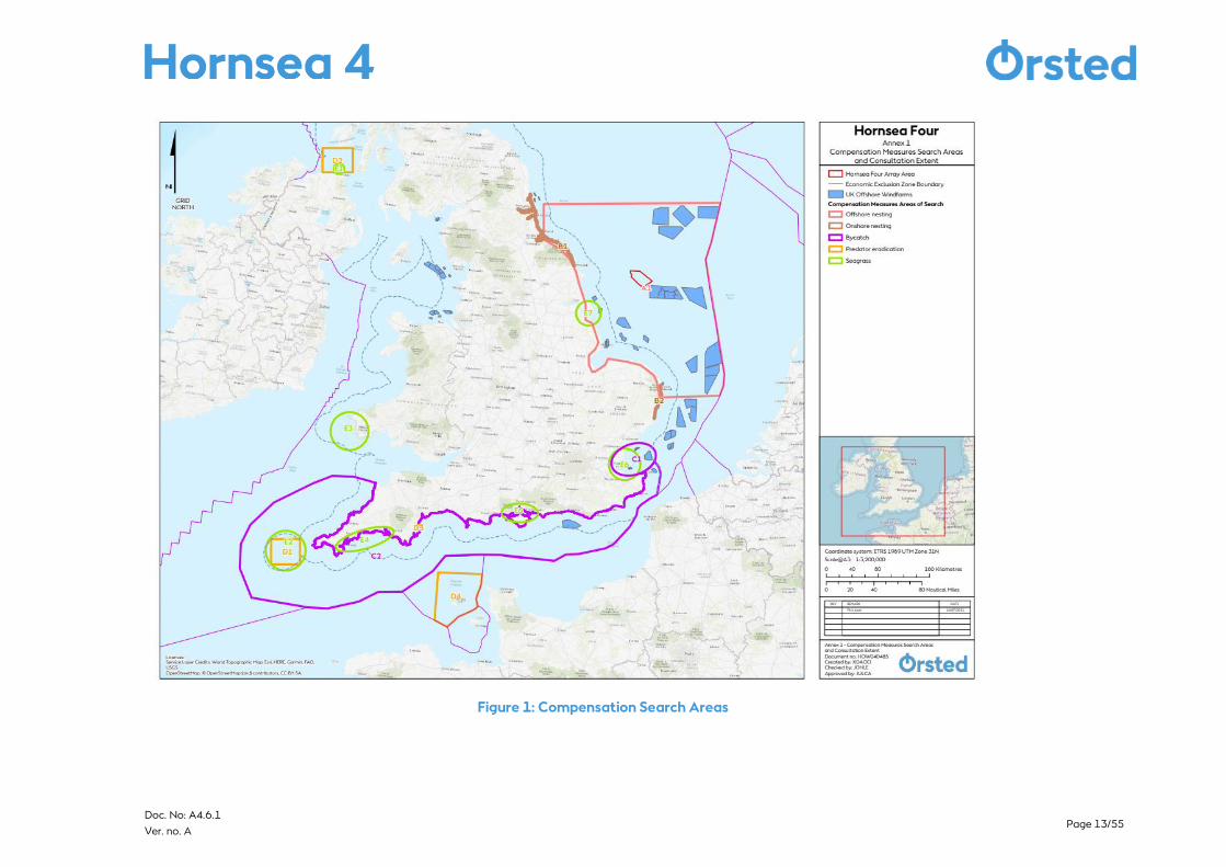
location ID and species being compensated are set out Table 1. It is anticipated that for
guillemot and razorbill a package of measures could be required, rather than a single
compensation measure. Compensation Measure Areas of Search are presented in the
accompanying Location Plan (see Figure 1).

Page 12/55 Doc. No: A4.6.1
Ver. no. A
Table 1: Compensation Measures, sub-options, locations, location ID and species being compensated.
Compensation Measure Option Location Location ID Kittiwake Gannet Guillemot RazorbillOffshore nesting New southern North Sea A1Offshore nesting Repurposed southern North Sea A1Onshore nesting New Cayton Bay to Newbiggin by the Sea B1
Suffolk Coast B2Bycatch Thames Estuary C1
South coast of England:Broadstairs to Plymouth
C2
Predator eradication Isles of Scilly D1
Rathlin Island, Moyle, Northern Ireland D2Torquay, Devon D3Guernsey and Aldernery D4
Fish habitat enhancement
Seagrass Rathlin Island, Moyle, Northern Ireland E1
Seagrass Isles of Scilly E2Seagrass Celtic Sea, Wales E3Seagrass Plymouth Sound to Helford River E4Seagrass Solent E5Seagrass Essex Estuaries E6
Page 13/55 Doc. No: A4.6.1
Ver. no. A
Figure 1: Compensation Search Areas

Page 14/55 Doc. No: A4.6.1
Ver. no. A
1.5 Programme
1.5.1.1 The high-level programme presented below is applicable to the implementation and
delivery of all compensation measures.
▪ Anticipated Hornsea Four DCO Granted – Q1 2023
▪ Compensation implementation licencing – 2022/24
▪ Compensation Implementation – 2023/24
▪ Offshore Construction of Hornsea Four Offshore Wind Farm – 2027/28
1.6 Decommissioning
1.6.1.1 The requirement for, and the exact nature of decommissioning the offshore and onshore
nesting structures, will be determined in consultation with the relevant authorities towards
the end of the 35-year operational life of Hornsea Four. The Applicant will design the
structures for a design life equal to that of the windfarm (i.e. 35 years plus 4 years to
establish the compensation measures, pre-wind farm operation. Therefore, the lifetime of
the structure is approximately 39 years). In the final few years of wind farm operation, the
Applicant will commence inspections and surveys of the bird nesting structures to determine
if an extension of the lifetime is possible.
1.6.1.2 It is currently anticipated that the predator eradication and bycatch measures
implementation will result in new management practices which shall continue for the
lifetime of Hornsea Four. Fish habitat enhancement (seagrass) compensation measure sites
will be left in perpetuity.
2 Offshore Artificial Nesting Platforms
2.1 Introduction and Background
2.1.1.1 The provision of an offshore artificial nest site(s) to increase the annual recruitment of black-
legged kittiwake (kittiwake) into the regional population of the southern North Sea is
considered a possible Compensatory Measure for a potential Adverse Effect on Site
Integrity at the Flamborough and Filey Coast Special Protection Area (FFC SPA). The
Applicant are considering two options by which to achieve this: construction a new offshore
nesting structure(s) or repurposing an existing Oil and Gas platform(s) that is due for
decommissioning.
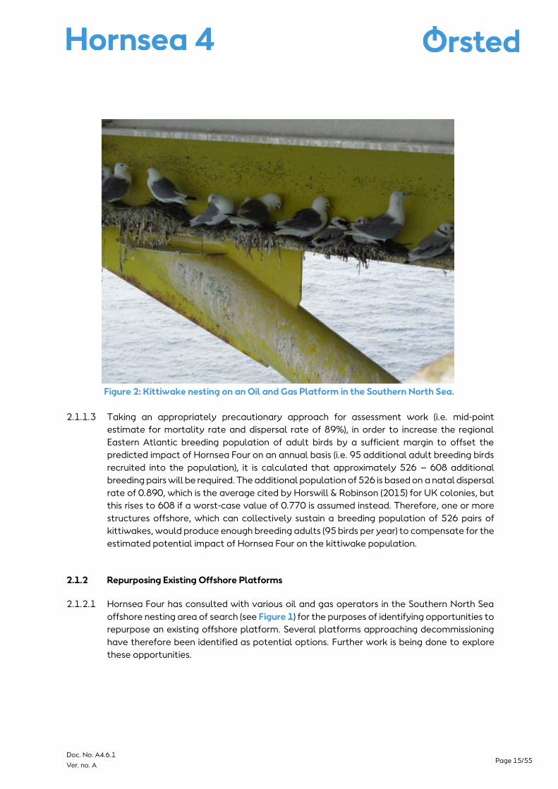
2.1.1.2 Kittiwake have been observed readily (APEM, 2021 and Niras, 2021) utilising man-made
structures and therefore it is considered that the establishment of an artificial nest site(s)
would provide a viable compensation option (see Figure 2). Successful establishment of
breeding colonies at a site would produce young, which would become part of the wider
Eastern Atlantic population of kittiwake, thereby maintaining the coherence of the network
of SPAs designated for kittiwake.
Page 15/55 Doc. No: A4.6.1
Ver. no. A
Figure 2: Kittiwake nesting on an Oil and Gas Platform in the Southern North Sea.
2.1.1.3 Taking an appropriately precautionary approach for assessment work (i.e. mid-point
estimate for mortality rate and dispersal rate of 89%), in order to increase the regional
Eastern Atlantic breeding population of adult birds by a sufficient margin to offset the
predicted impact of Hornsea Four on an annual basis (i.e. 95 additional adult breeding birds
recruited into the population), it is calculated that approximately 526 – 608 additional
breeding pairs will be required. The additional population of 526 is based on a natal dispersal
rate of 0.890, which is the average cited by Horswill & Robinson (2015) for UK colonies, but
this rises to 608 if a worst-case value of 0.770 is assumed instead. Therefore, one or more
structures offshore, which can collectively sustain a breeding population of 526 pairs of
kittiwakes, would produce enough breeding adults (95 birds per year) to compensate for the
estimated potential impact of Hornsea Four on the kittiwake population.
2.1.2 Repurposing Existing Offshore Platforms
2.1.2.1 Hornsea Four has consulted with various oil and gas operators in the Southern North Sea
offshore nesting area of search (see Figure 1) for the purposes of identifying opportunities to
repurpose an existing offshore platform. Several platforms approaching decommissioning
have therefore been identified as potential options. Further work is being done to explore
these opportunities.
Page 16/55 Doc. No: A4.6.1
Ver. no. A
2.1.2.2 As an example, one platform that has been identified as a potential candidate platform,
installed after 2000, having now reached the end of its production life, is a normally
unattended installation (NUI), designed to be primarily operated remotely.
2.1.3 New Offshore Platforms
2.1.3.1 Additionally, the Applicant is considering the construction of purpose-built offshore nesting
platform(s) within the Southern North Sea offshore nesting area of search (see Figure 1). The
design, construction and operation of a new offshore platform for the purposes of kittiwake
nesting would follow the description contained in the following sections.
2.2 Offshore Platform Design
2.2.1 Repurposing Existing Offshore Platforms
2.2.1.1 The Applicant could utilise an existing offshore platform (potentially an existing oil and gas
structure or similar), and use the foundation to:
A. design, construct and install a new topside once the existing topside structure has been
removed and decommissioned,
B. repurpose the existing topside structure by adding additional nesting.
2.2.1.2 For example, a platform currently under design consideration consists of a topside platform
of 16 x 12.75m area sitting atop a 47m high jacket foundation in 25m water depth. This
analogue is used for the preceding description.
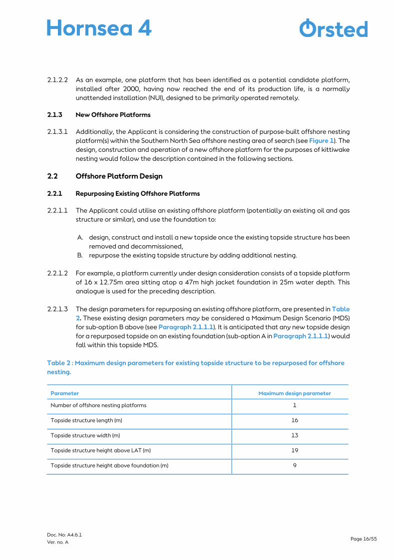
2.2.1.3 The design parameters for repurposing an existing offshore platform, are presented in Table
2. These existing design parameters may be considered a Maximum Design Scenario (MDS)
for sub-option B above (see Paragraph 2.1.1.1). It is anticipated that any new topside design
for a repurposed topside on an existing foundation (sub-option A in Paragraph 2.1.1.1) would
fall within this topside MDS.
Table 2 : Maximum design parameters for existing topside structure to be repurposed for offshore
nesting.
Parameter Maximum design parameter
Number of offshore nesting platforms 1
Topside structure length (m) 16
Topside structure width (m) 13
Topside structure height above LAT (m) 19
Topside structure height above foundation (m) 9
Page 17/55 Doc. No: A4.6.1
Ver. no. A
2.2.2 New Offshore Platforms
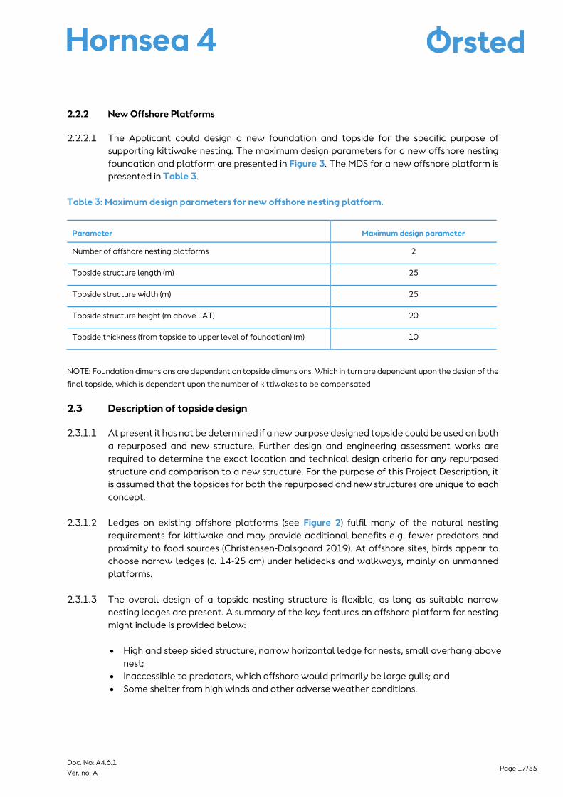
2.2.2.1 The Applicant could design a new foundation and topside for the specific purpose of
supporting kittiwake nesting. The maximum design parameters for a new offshore nesting
foundation and platform are presented in Figure 3. The MDS for a new offshore platform is
presented in Table 3.
Table 3: Maximum design parameters for new offshore nesting platform.
Parameter Maximum design parameter
Number of offshore nesting platforms 2
Topside structure length (m) 25
Topside structure width (m) 25
Topside structure height (m above LAT) 20
Topside thickness (from topside to upper level of foundation) (m) 10
NOTE: Foundation dimensions are dependent on topside dimensions. Which in turn are dependent upon the design of the
final topside, which is dependent upon the number of kittiwakes to be compensated
2.3 Description of topside design
2.3.1.1 At present it has not be determined if a new purpose designed topside could be used on both
a repurposed and new structure. Further design and engineering assessment works are
required to determine the exact location and technical design criteria for any repurposed
structure and comparison to a new structure. For the purpose of this Project Description, it
is assumed that the topsides for both the repurposed and new structures are unique to each
concept.
2.3.1.2 Ledges on existing offshore platforms (see Figure 2) fulfil many of the natural nesting
requirements for kittiwake and may provide additional benefits e.g. fewer predators and
proximity to food sources (Christensen-Dalsgaard 2019). At offshore sites, birds appear to
choose narrow ledges (c. 14-25 cm) under helidecks and walkways, mainly on unmanned
platforms.
2.3.1.3 The overall design of a topside nesting structure is flexible, as long as suitable narrow
nesting ledges are present. A summary of the key features an offshore platform for nesting
might include is provided below:
• High and steep sided structure, narrow horizontal ledge for nests, small overhang above
nest;
• Inaccessible to predators, which offshore would primarily be large gulls; and
• Some shelter from high winds and other adverse weather conditions.
Page 18/55 Doc. No: A4.6.1
Ver. no. A
2.3.1.4 In addition, the topside design may include a shelter and potentially CCTV to enable
monitoring of the seabirds.
2.4 Description of foundation design
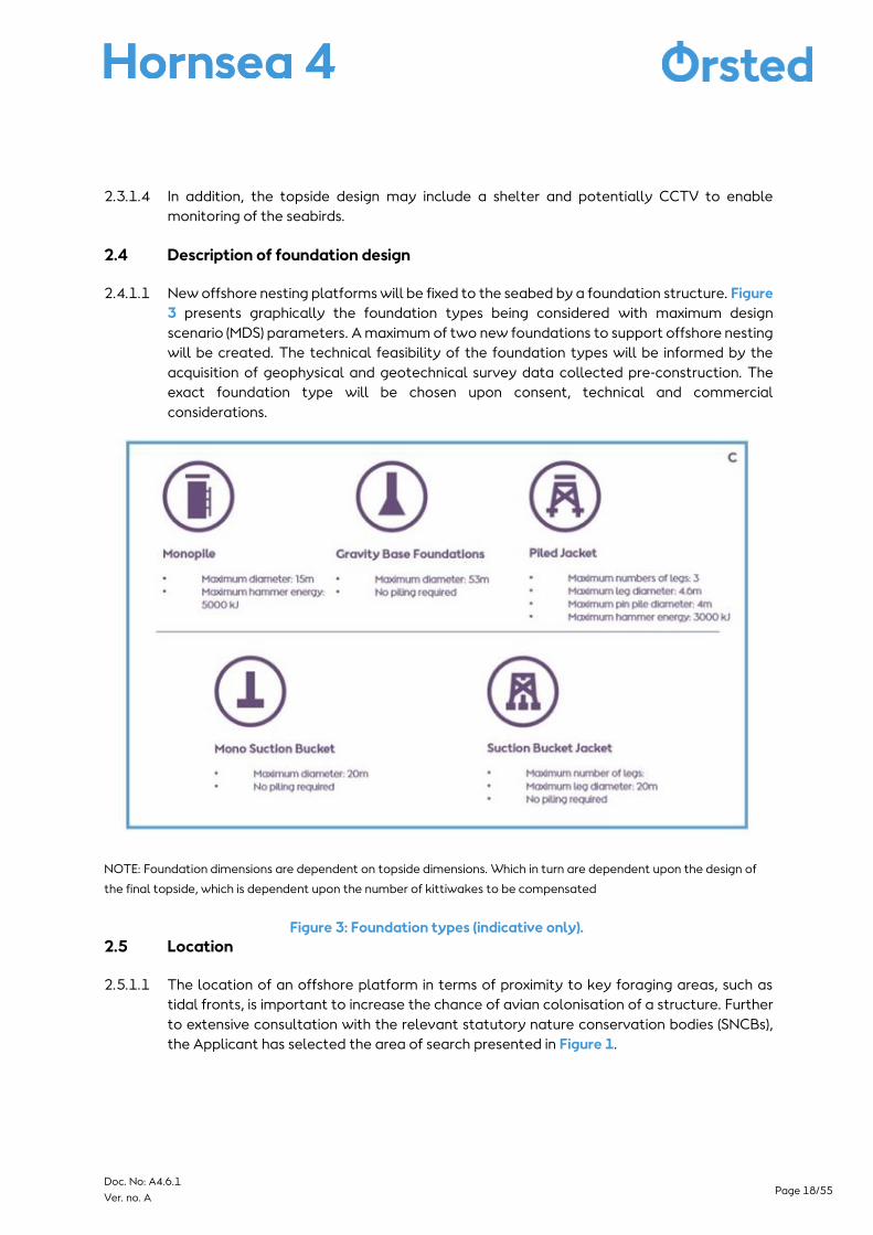
2.4.1.1 New offshore nesting platforms will be fixed to the seabed by a foundation structure. Figure
3 presents graphically the foundation types being considered with maximum design
scenario (MDS) parameters. A maximum of two new foundations to support offshore nesting
will be created. The technical feasibility of the foundation types will be informed by the
acquisition of geophysical and geotechnical survey data collected pre-construction. The
exact foundation type will be chosen upon consent, technical and commercial
considerations.
NOTE: Foundation dimensions are dependent on topside dimensions. Which in turn are dependent upon the design of
the final topside, which is dependent upon the number of kittiwakes to be compensated
Figure 3: Foundation types (indicative only).
2.5 Location
2.5.1.1 The location of an offshore platform in terms of proximity to key foraging areas, such as
tidal fronts, is important to increase the chance of avian colonisation of a structure. Further
to extensive consultation with the relevant statutory nature conservation bodies (SNCBs),
the Applicant has selected the area of search presented in Figure 1.
Page 19/55 Doc. No: A4.6.1
Ver. no. A
2.5.1.2 The site selection process for the offshore artificial nesting structures is being undertaken
via a heatmapping exercise. Ecological criteria will form a primary consideration, with
technical and commercial considerations also considered. The heatmap will be applied
using 5km search grids, across the entire search area, each with unique identifying codes.
5km search grids are being used as it is considered that they are large enough to provide the
flexibility required for ground conditions to ensure the structures can be suitably micro-sited.
2.5.1.3 Statutory stakeholders have advised that site selection should avoid the core foraging
range distance from FFC SPA, and it would be beneficial for the location to be close enough
to FFC SPA for colony interchange to be a possibility. The search area for a breeding colony
would therefore be located approximately beyond 55km and broadly around 100km from
the FFC SPA. We will also take into consideration other environmental information such as
information on prey and will take into consideration planned, under construction and
operational wind farm locations.
2.5.1.4 In respect of commercial site selection criteria, existing assets have been identified using
open data sources from The Crown Estate, including offshore wind farms, minerals and
aggregates, offshore mines, oil and gas and dredging disposal sites. Additionally, known
future assets, such as Round Four offshore wind farm lease areas and carbon capture,
utilisation and storage (CCUS), have been identified. A 500m buffer has been applied to all
assets and will be excluded from site selection. The Applicant is undertaking continued
consultation with The Crown Estate and operators to ensure commercial criteria used for
site selection is appropriate and robust.
2.5.1.5 Further engagement with stakeholders and oil and gas operators is ongoing and additional
information is being gathered to inform and refine the site selection process.
2.6 Construction
2.6.1 Repurposing Existing Offshore Platforms
2.6.1.1 Foundation installation is not required if repurposing an existing offshore platform. However
minor modifications to the existing offshore platform foundation may be required.
Foundation repurposing installation activities could include repairs, modifications, or
reinforcement of existing foundation infrastructure and are set out in a maximum design
scenario.
2.6.1.2 All modifications would be undertaken using either or a combination of DP and JUV vessels
as set out in Table 4.
2.6.2 Topside installation
2.6.2.1 Generally, topside(s) are installed using the following process:
• Topsides are installed upon their respective foundation type (see Section 2.4);
• Topsides are picked up from port. This vessel will typically be a JUV to ensure a stable
platform for installation vessels when on site. JUVs are assumed to have up to six legs
Page 20/55 Doc. No: A4.6.1
Ver. no. A
with an average spudcan area of 170 m2 per foot. In general, the JUV will carry all the
components for topside installation on a single trip;
• The installation vessel will then transit to the installation area and the components will
be lifted onto the existing transition piece or foundation substructure, by the crane on
the installation vessel. Each topside will be assembled on site in this fashion with
technicians fastening components together as they are lifted into place. The exact
methodology for the assembly is dependent on the topside type (new or repurposed)
and installation contractor, and will be defined in the pre-construction phase after grant
of consent; or
• Alternatively, the topside components may be loaded onto barges or dedicated
transport vessels at port and installed as above by an installation vessel that remains
on site throughout the installation campaign.
2.6.2.2 Each installation vessel or barge may be assisted by a range of support and transport
vessels. These are typically smaller vessels that may be tugs, guard vessels, anchor handling
vessels, or similar. These vessels will primarily make the same movements to, from and
around the installation area as the installation vessels they are supporting.
2.6.2.3 The foundation and topside may be transported on the same transport vessel/barge, or
separately. The foundation may also be transported by the installation vessel.
2.6.3 Constructing New Offshore Platforms
2.6.3.1 New offshore platforms are generally installed in two stages, firstly the foundation is
installed as described in Table 4, and secondly the topside will be lifted from a transport
vessel/barge onto the foundation (as per Section2.6.2). The details presented in Table 4 are
indicative and based on our understanding at this current time. Vessel numbers relate to 2
new foundation and topside structure installations and finalisations.
2.6.3.2 The foundation and topside may be transported on the same transport vessel/barge, or
separately. The foundation may also be transported by the installation vessel. The vessel
numbers are presented in the MDS.
Page 21/55 Doc. No: A4.6.1
Ver. no. A
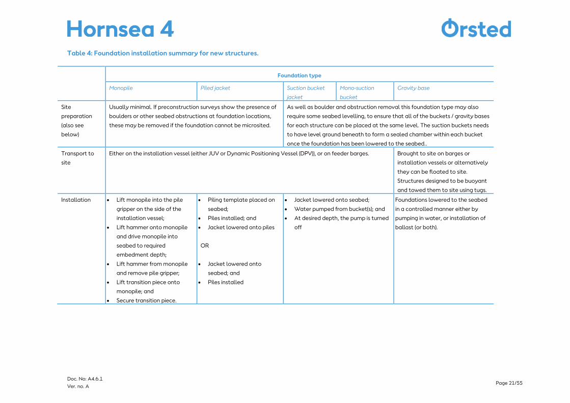
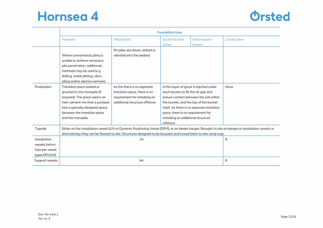
Table 4: Foundation installation summary for new structures.
Foundation type
Monopile Piled jacket Suction bucket
jacket
Mono-suction
bucket
Gravity base
Site
preparation
(also see
below)
Usually minimal. If preconstruction surveys show the presence of
boulders or other seabed obstructions at foundation locations,
these may be removed if the foundation cannot be microsited.
As well as boulder and obstruction removal this foundation type may also
require some seabed levelling, to ensure that all of the buckets / gravity bases
for each structure can be placed at the same level. The suction buckets needs
to have level ground beneath to form a sealed chamber within each bucket
once the foundation has been lowered to the seabed..
Transport to
site
Either on the installation vessel (either JUV or Dynamic Positioning Vessel (DPV)), or on feeder barges. Brought to site on barges or
installation vessels or alternatively
they can be floated to site.
Structures designed to be buoyant
and towed them to site using tugs.
Installation • Lift monopile into the pile
gripper on the side of the
installation vessel;
• Lift hammer onto monopile
and drive monopile into
seabed to required
embedment depth;
• Lift hammer from monopile
and remove pile gripper;
• Lift transition piece onto
monopile; and
• Secure transition piece.
• Piling template placed on
seabed;
• Piles installed; and
• Jacket lowered onto piles
OR
• Jacket lowered onto
seabed; and
• Piles installed
• Jacket lowered onto seabed;
• Water pumped from bucket(s); and
• At desired depth, the pump is turned
off
Foundations lowered to the seabed
in a controlled manner either by
pumping in water, or installation of
ballast (or both).
Page 22/55 Doc. No: A4.6.1
Ver. no. A
Foundation type
Monopile Piled jacket Suction bucket
jacket
Mono-suction
bucket
Gravity base
Where conventional piling is
unable to achieve necessary
pile penetration, additional
methods may be used (e.g.
drilling, water jetting, vibro-
piling and/or electro-osmosis).
Pin piles are driven, drilled or
vibrated into the seabed.
Finalisation Transition piece bolted or
grouted to the monopile (if
required). The grout used is an
inert cement mix that is pumped
into a specially designed space
between the transition piece
and the monopile.
As the there is no separate
transition piece, there is no
requirement for installing an
additional structure offshore.
A thin layer of grout is injected under
each bucket to fill the air gap and
ensure contact between the soil within
the bucket, and the top of the bucket
itself. As there is no separate transition
piece, there is no requirement for
installing an additional structure
offshore.
None
Topside Either on the installation vessel (JUV or Dynamic Positioning Vessel (DPV)), or on feeder barges. Brought to site on barges or installation vessels or
alternatively they can be floated to site. Structures designed to be buoyant and towed them to site using tugs.
Installation
vessels (return
trips per vessel
type( DP/JUV))
16 8
Support vessels 64 8

Page 23/55 Doc. No: A4.6.1
Ver. no. A
Foundation type
Monopile Piled jacket Suction bucket
jacket
Mono-suction
bucket
Gravity base
Transport
vessels (barges)
40 16
Transport
vessels (tugs)
30 0

Page 24/55 Doc. No: A4.6.1
Ver. no. A
2.6.4 Ancillary operations
2.6.4.1 Some form of Seabed preparation (boulder and sandwave clearance), unexploded
ordnance (UxO) clearance and Scour protection may be required for each foundation type
in Table 4. Seabed preparations are detailed in Section 4.8.8. of the Project Description (see
the Hornsea Four Document Library). Unexploded ordnance (UXO), boulder and sandwave
clearance for foundations are as per Section 4.8.8. of the Project Description.
2.6.4.2 Scour protection is designed to prevent foundation structures being undermined by
hydrodynamic and sedimentary processes, resulting in seabed erosion and subsequent
scour hole formation. The preferred scour protection solution may comprise a rock armour
layer resting on a filter layer of smaller graded rocks. The maximum diameter of the rocks
used would be 1 m and the maximum thickness of scour protection layer would be 2 m.
2.6.5 Maximum design parameters for foundations
2.6.5.1 Each environmental assessment considers the range of foundations options (including
monopiles, suction bucket jacket foundations, piled jacket foundations, mono suction
buckets and gravity base structures) and assesses the foundation type which presents the
maximum design scenario for the relevant receptor(s).
2.6.5.2 Table 5 presents the MDS. Full details of all foundation types considered are provided in
Section 4.8.4 of Volume 1: Project Description (see the Hornsea Four Document Library).
Table 5: Indicative Maximum design* parameters for the new offshore nesting platform
foundations.
Maximum design
parameters
Maximum related foundation
type
Total Number 2 -
Number of Piles (per foundation) 16 Piled Jacket
Piling hammer energy (kj) 5,000 (3,000) Monopile (if pin piles)
Seabed Preparation Area 3.739 m2 GBS
Seabed Structure Area 2,206 m2 GBS
Seabed Scour Protection Area 4,587 m2 GBS
Seabed Total Permanent Area 6,793 m2 GBS
Drill Spoil Volume (average; assumes 10% drilling) 264 m3 Piled Jacket
Seabed Preparation (Spoil) Volume 6,234 m3 GBS (Large OSS)
Scour Protection Volume 9,173 m3 HVDC
* NOTE: The MDS is provided based on the assumption of a 39-year design life. Should this be increased then MDS
would need to be revisited and any assessments updated accordingly.
Page 25/55 Doc. No: A4.6.1
Ver. no. A
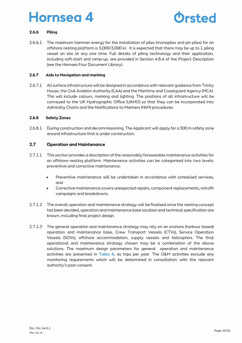
2.6.6 Piling
2.6.6.1 The maximum hammer energy for the installation of piles (monopiles and pin piles) for an
offshore nesting platform is 5,000/3,000 kJ. It is expected that there may be up to 1 piling
vessel on site at any one time. Full details of piling technology and their application,
including soft-start and ramp-up, are provided in Section 4.8.4 of the Project Description
(see the Hornsea Four Document Library).
2.6.7 Aids to Navigation and marking
2.6.7.1 All surface infrastructure will be designed in accordance with relevant guidance from Trinity
House, the Civil Aviation Authority (CAA) and the Maritime and Coastguard Agency (MCA).
This will include colours, marking and lighting. The positions of all infrastructure will be
conveyed to the UK Hydrographic Office (UKHO) so that they can be incorporated into
Admiralty Charts and the Notifications to Mariners (NtM) procedures.
2.6.8 Safety Zones
2.6.8.1 During construction and decommissioning, The Applicant will apply for a 500 m safety zone
around infrastructure that is under construction.
2.7 Operation and Maintenance
2.7.1.1 This section provides a description of the reasonably foreseeable maintenance activities for
an offshore nesting platform. Maintenance activities can be categorised into two levels:
preventive and corrective maintenance:
• Preventive maintenance will be undertaken in accordance with scheduled services;
and
• Corrective maintenance covers unexpected repairs, component replacements, retrofit
campaigns and breakdowns.
2.7.1.2 The overall operation and maintenance strategy will be finalised once the nesting concept
has been decided, operation and maintenance base location and technical specification are
known, including final project design.
2.7.1.3 The general operation and maintenance strategy may rely on an onshore (harbour based)
operation and maintenance base, Crew Transport Vessels (CTVs), Service Operation
Vessels (SOVs), offshore accommodation, supply vessels and helicopters. The final
operational and maintenance strategy chosen may be a combination of the above
solutions. The maximum design parameters for general operation and maintenance
activities are presented in Table 6, as trips per year. The O&M activities exclude any
monitoring requirements which will be determined in consultation with the relevant
authority’s post-consent.
Page 26/55 Doc. No: A4.6.1
Ver. no. A
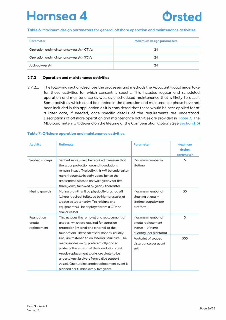
Table 6: Maximum design parameters for general offshore operation and maintenance activities.
Parameter Maximum design parameters
Operation and maintenance vessels - CTVs: 24
Operation and maintenance vessels - SOVs 24
Jack-up vessels 24
2.7.2 Operation and maintenance activities
2.7.2.1 The following section describes the processes and methods the Applicant would undertake
for those activities for which consent is sought. This includes regular and scheduled
operation and maintenance as well as unscheduled maintenance that is likely to occur.
Some activities which could be needed in the operation and maintenance phase have not
been included in this application as it is considered that these would be best applied for at
a later date, if needed, once specific details of the requirements are understood.
Descriptions of offshore operation and maintenance activities are provided in Table 7. The
MDS parameters will depend on the lifetime of the Compensation Options (see Section 1.5)
Table 7: Offshore operation and maintenance activities.
Activity Rationale Parameter Maximum
design
parameter
Seabed surveys Seabed surveys will be required to ensure that
the scour protection around foundations
remains intact. Typically, this will be undertaken
more frequently in early years, hence the
assessment is based on twice yearly for first
three years; followed by yearly thereafter
Maximum number in
lifetime
5
Marine growth Marine growth will be physically brushed off
(where required) followed by high-pressure jet
wash (sea water only). Technicians and
equipment will be deployed from a CTV or
similar vessel.
Maximum number of
cleaning events –
lifetime quantity (per
platform)
35
Foundation
anode
replacement
This includes the removal and replacement of
anodes, which are required for corrosion
protection (internal and external to the
foundation). These sacrificial anodes, usually
zinc, are fastened to an external structure. The
metal erodes away preferentially and so
protects the erosion of the foundation steel.
Anode replacement works are likely to be
undertaken via divers from a dive support
vessel. One turbine anode replacement event is
planned per turbine every five years.
Maximum number of
anode replacement
events – lifetime
quantity (per platform)
5
Footprint of seabed
disturbance per event
(m2)
300
Page 27/55 Doc. No: A4.6.1
Ver. no. A
2.8 Decommissioning
2.8.1.1 The requirement for, and the exact nature of, decommissioning will be determined in
consultation with the relevant authorities towards the end of the 35-year operational life
of Hornsea Four.
2.9 Monitoring and Adaptive Management
2.9.1.1 Monitoring forms an integral component of the Compensatory Measure and will be
developed with relevant stakeholders. The delivery of the Compensation Measure will be
planned with relevant monitoring of kittiwake undertaken at appropriate timescales to
maximise its usefulness to Hornsea Four and the wider scientific community. The success in
deployment of the artificial nest structures will be monitored through observations of the
number of breeding birds and their breeding success. Monitoring of these rates will follow
the standard methods provided by Walsh et al., (1995) and specified by the Joint Nature
Conservation Committee’s (JNCC) Seabird Monitoring Programme which acts as the hub of
seabird population information. Collection of seabird data in this format will permit
comparisons to be made with on-going monitoring at existing colonies along the east coast
of England, including that undertaken at the FFC SPA (Babcock et al., 2018). In order to
monitor the number of breeding birds and their breeding success whole colony counts and
productivity monitoring will be conducted at the artificial nest site. The precise nature of
monitoring at the structure will be influenced by the final form and locations the
Compensation Measure takes. In addition to monitoring, it is likely that further research will
also be undertaken such as on seabird prey and Hornsea Four are engaged in ongoing
discussions with stakeholders on the potential research topics.
2.9.1.2 The Compensation Measure is a long-term commitment, with monitoring and adaptive
management built in to ensure the long-term success of the measure. Adaptive
management is an iterative, post-consent process which combines management measures
and subsequent monitoring with the aim of improving effectiveness whilst also updating
knowledge and improving decision making over time. Adaptive management will be an
important component of the Compensation measure and will be used as a method to
address unforeseen issues or deviations from expected time scales (i.e. colonisation rate of
structure). Adaptive management measures are designed to support the Compensation
Measure once functioning (post construction) as a way of furthering the success and
supporting resilience of the measure. It is worth noting at this stage that any adaptive
measures will be thoroughly discussed and explored with relevant stakeholders prior to the
implementation of any option.
2.10 Summary of Offshore Artificial Nesting Structures
2.10.1.1 Artificial nesting structures (offshore structures new and repurposed) are considered to be
primary Compensation Measures. New or a repurposed structure would each be capable of
delivering the level of compensation required with greater capacity available. A detailed
evidence report will be submitted with the application which demonstrates the evidence to
support the scale and efficacy of the compensation measure ensuring that significant
contingency is built into the measure to provide the necessary confidence that it will
substantively offset the impact. These Compensation Measures are effective, feasible and
securable measures that can be implemented prior to the impact occurring and sustainable
for the lifetime of the project. Further details of the compensation plan and roadmaps to
delivery will be provided with the DCO application submission. The Applicant has
undertaken engagement with statutory and non-statutory stakeholders including The
Page 28/55 Doc. No: A4.6.1
Ver. no. A
Crown Estate and oil and gas operators throughout the development of these measures
and consultation will be ongoing.
3 Onshore Artificial Nesting Platform
3.1 Introduction and Background
3.1.1.1 Onshore artificial nesting structures are being proposed for kittiwake by Hornsea Four and
are put forward for if following Examination, the Secretary of State considers that an
additional or alternative (alternative to offshore nesting) measure is required to the
proposed primary measures. The approach to site selection and design are primarily driven
by ecological/habitat requirements of the ornithology interests to increase the likelihood
of colonisation and ensure the success of the structures. The artificial nesting structures will
be located within one of two search zones (one in East Suffolk, and the other between Blyth
and Newbiggin). The structures will be designed to accommodate the level of
compensation required with greater capacity available for kittiwake and will accord with
the design principles and indicative maximum parameters set out below.
3.2 Design Principles
3.2.1.1 The design principles for onshore artificial nesting structures are subject to significant
further development; however, design principles of direct relevance to the size or
appearance of the structures are as follows:
• Steep sided with a near vertical back wall and narrow horizontal ledges.
• Located close to water, facing out to sea (i.e. nest adjacent to/above harbour
waters/sea).
• Inaccessible to predators (additional anti-predation features may be required at
some sites – e.g. fences/ barriers to deter mammalian predators (e.g. foxes and rats)
and dependent on design bird spikes may be required as avian predator deterrents).
• Nesting ledges located above the level of highest astronomical tide and beyond the
reach of wave or tidal action.
• Adequate ledge dimensions: Horizontal ledges 20 cm width; length per pair from 30
cm (working length 40 cm); and height between ledges at a minimum of 40 cm and
maximum of 60cm. (Note these may be subject to change based on feedback from
the stakeholders during detailed design).
• Minimum height at which the lowest shelves should begin depends whether the
structure is located directly over water or set back slightly, as well as the level of
human disturbance anticipated.
• Overhang/roof to buffer against weather conditions as to act as and additional
predator deterrents.
• Vertical wall leaning slightly forward (working angle of 5°; to minimise lower ledges
becoming fouled by droppings and reduce predation risk).
• Using materials which are in-keeping with the structure’s surroundings whilst ensuring
they meet the requirements of kittiwake’s natural habitat as much as possible.
• Higher ledges could be wider than lower ledges (to prevent lower ledges becoming
fouled by droppings) (BTO Field Guide No. 23, du Feu (2015)). However, wider upper
ledges may increase predation risk/ allow non target species to nest.
Page 29/55 Doc. No: A4.6.1
Ver. no. A
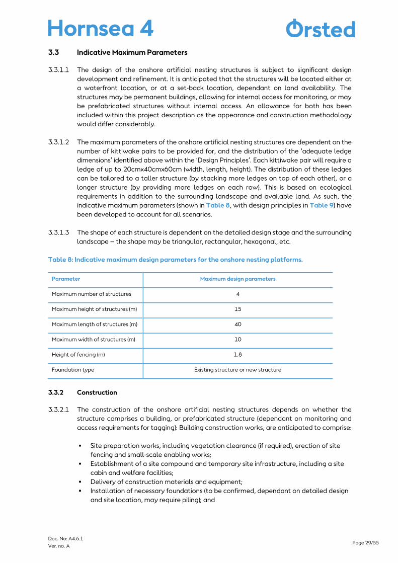
3.3 Indicative Maximum Parameters
3.3.1.1 The design of the onshore artificial nesting structures is subject to significant design
development and refinement. It is anticipated that the structures will be located either at
a waterfront location, or at a set-back location, dependant on land availability. The
structures may be permanent buildings, allowing for internal access for monitoring, or may
be prefabricated structures without internal access. An allowance for both has been
included within this project description as the appearance and construction methodology
would differ considerably.
3.3.1.2 The maximum parameters of the onshore artificial nesting structures are dependent on the
number of kittiwake pairs to be provided for, and the distribution of the ‘adequate ledge
dimensions’ identified above within the ‘Design Principles’. Each kittiwake pair will require a
ledge of up to 20cmx40cmx60cm (width, length, height). The distribution of these ledges
can be tailored to a taller structure (by stacking more ledges on top of each other), or a
longer structure (by providing more ledges on each row). This is based on ecological
requirements in addition to the surrounding landscape and available land. As such, the
indicative maximum parameters (shown in Table 8, with design principles in Table 9) have
been developed to account for all scenarios.
3.3.1.3 The shape of each structure is dependent on the detailed design stage and the surrounding
landscape – the shape may be triangular, rectangular, hexagonal, etc.
Table 8: Indicative maximum design parameters for the onshore nesting platforms.
Parameter Maximum design parameters
Maximum number of structures 4
Maximum height of structures (m) 15
Maximum length of structures (m) 40
Maximum width of structures (m) 10
Height of fencing (m) 1.8
Foundation type Existing structure or new structure
3.3.2 Construction
3.3.2.1 The construction of the onshore artificial nesting structures depends on whether the
structure comprises a building, or prefabricated structure (dependant on monitoring and
access requirements for tagging): Building construction works, are anticipated to comprise:
▪ Site preparation works, including vegetation clearance (if required), erection of site
fencing and small-scale enabling works;
▪ Establishment of a site compound and temporary site infrastructure, including a site
cabin and welfare facilities;
▪ Delivery of construction materials and equipment;
▪ Installation of necessary foundations (to be confirmed, dependant on detailed design
and site location, may require piling); and
Page 30/55 Doc. No: A4.6.1
Ver. no. A
▪ Construction of the nesting structures on-site, methodology of which is dependent on
the materials to be used (to be agreed as part of detailed design). Materials used for
the building may comprise concrete, wood, or metal).
3.3.2.2 Prefabricated structure construction works are anticipated to comprise:
▪ Site preparation works, including vegetation clearance (if required), erection of site
fencing and small-scale enabling works;
▪ Establishment of a site compound and temporary site infrastructure, including a site
cabin and welfare facilities;
▪ Delivery of prefabricated components of the nesting structures and equipment;
▪ Installation of necessary foundations (to be confirmed, dependant on detailed design
and site location, may require piling); and
▪ Assembly and Installation of the nesting structures on-site, methodology of which is
dependent on the materials to be used (to be agreed as part of detailed design).
Materials used for the prefabricated structure may comprise wood or metal.
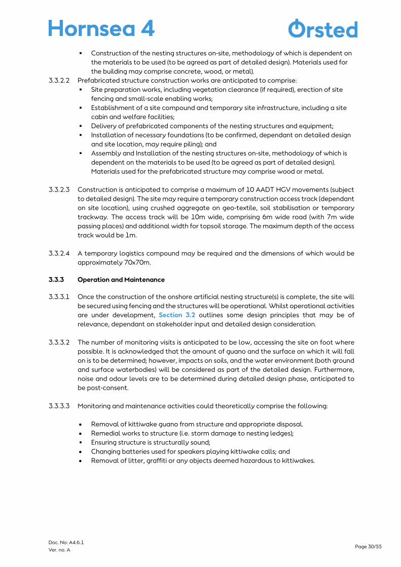
3.3.2.3 Construction is anticipated to comprise a maximum of 10 AADT HGV movements (subject
to detailed design). The site may require a temporary construction access track (dependant
on site location), using crushed aggregate on geo-textile, soil stabilisation or temporary
trackway. The access track will be 10m wide, comprising 6m wide road (with 7m wide
passing places) and additional width for topsoil storage. The maximum depth of the access
track would be 1m.
3.3.2.4 A temporary logistics compound may be required and the dimensions of which would be
approximately 70x70m.
3.3.3 Operation and Maintenance
3.3.3.1 Once the construction of the onshore artificial nesting structure(s) is complete, the site will
be secured using fencing and the structures will be operational. Whilst operational activities
are under development, Section 3.2 outlines some design principles that may be of
relevance, dependant on stakeholder input and detailed design consideration.
3.3.3.2 The number of monitoring visits is anticipated to be low, accessing the site on foot where
possible. It is acknowledged that the amount of guano and the surface on which it will fall
on is to be determined; however, impacts on soils, and the water environment (both ground
and surface waterbodies) will be considered as part of the detailed design. Furthermore,
noise and odour levels are to be determined during detailed design phase, anticipated to
be post-consent.
3.3.3.3 Monitoring and maintenance activities could theoretically comprise the following:
• Removal of kittiwake guano from structure and appropriate disposal.
• Remedial works to structure (i.e. storm damage to nesting ledges);
▪ Ensuring structure is structurally sound;
• Changing batteries used for speakers playing kittiwake calls; and
• Removal of litter, graffiti or any objects deemed hazardous to kittiwakes.
Page 31/55 Doc. No: A4.6.1
Ver. no. A
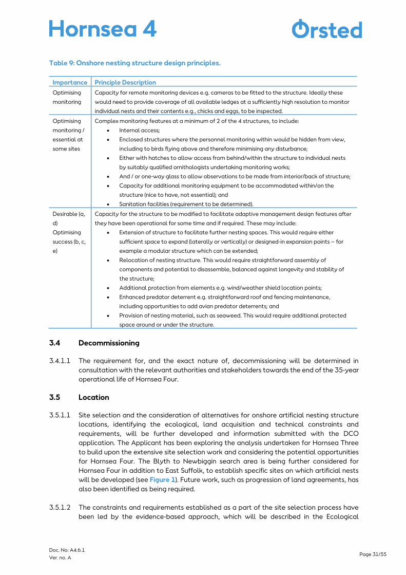
Table 9: Onshore nesting structure design principles.
Importance Principle Description
Optimising
monitoring
Capacity for remote monitoring devices e.g. cameras to be fitted to the structure. Ideally these
would need to provide coverage of all available ledges at a sufficiently high resolution to monitor
individual nests and their contents e.g., chicks and eggs, to be inspected.
Optimising
monitoring /
essential at
some sites
Complex monitoring features at a minimum of 2 of the 4 structures, to include:
• Internal access;
• Enclosed structures where the personnel monitoring within would be hidden from view,
including to birds flying above and therefore minimising any disturbance;
• Either with hatches to allow access from behind/within the structure to individual nests
by suitably qualified ornithologists undertaking monitoring works;
• And / or one-way glass to allow observations to be made from interior/back of structure;
• Capacity for additional monitoring equipment to be accommodated within/on the
structure (nice to have, not essential); and
• Sanitation facilities (requirement to be determined).
Desirable (a,
d)
Optimising
success (b, c,
e)
Capacity for the structure to be modified to facilitate adaptive management design features after
they have been operational for some time and if required. These may include:
• Extension of structure to facilitate further nesting spaces. This would require either
sufficient space to expand (laterally or vertically) or designed-in expansion points – for
example a modular structure which can be extended;
• Relocation of nesting structure. This would require straightforward assembly of
components and potential to disassemble, balanced against longevity and stability of
the structure;
• Additional protection from elements e.g. wind/weather shield location points;
• Enhanced predator deterrent e.g. straightforward roof and fencing maintenance,
including opportunities to add avian predator deterrents; and
• Provision of nesting material, such as seaweed. This would require additional protected
space around or under the structure.
3.4 Decommissioning
3.4.1.1 The requirement for, and the exact nature of, decommissioning will be determined in
consultation with the relevant authorities and stakeholders towards the end of the 35-year
operational life of Hornsea Four.
3.5 Location
3.5.1.1 Site selection and the consideration of alternatives for onshore artificial nesting structure
locations, identifying the ecological, land acquisition and technical constraints and
requirements, will be further developed and information submitted with the DCO
application. The Applicant has been exploring the analysis undertaken for Hornsea Three
to build upon the extensive site selection work and considering the potential opportunities
for Hornsea Four. The Blyth to Newbiggin search area is being further considered for
Hornsea Four in addition to East Suffolk, to establish specific sites on which artificial nests
will be developed (see Figure 1). Future work, such as progression of land agreements, has
also been identified as being required.
3.5.1.2 The constraints and requirements established as a part of the site selection process have
been led by the evidence-based approach, which will be described in the Ecological
Page 32/55 Doc. No: A4.6.1
Ver. no. A
Evidence reports submitted as part of the Applicants Development Consent Order
application. Initial consultation has been carried out and no significant obstacles to
development have been identified.
3.5.1.3 A full account of the ecological criteria for the site selection process undertaken to date
will be submitted with the DCO application. The purpose of site selection has been to
identify an area to host onshore artificial nesting sites that will be occupied by new recruits
in the English southern North Sea, whilst contributing to an increase of breeding adults to
the Eastern Atlantic kittiwake population. The principles influencing this initial site selection
work comprise:
• Locations which kittiwake with certainty will be able to find (for example either
locations where there are existing (smaller) populations of kittiwake, or where there
are factors which attract kittiwake);
• Locations where there is evidence of stable/increasing productivity and evidence of
an expanding population (as a proxy for favourable prey resource);
• Locations where there is a lack of existing natural or man-made habitat (locations
where kittiwake are attempting to nest in unfavourable conditions such as ground
nesting);
• Waterfront locations away from urban housing which minimise human interaction
and where purpose built onshore artificial nests can ideally overhang water, to mimic
the natural nesting conditions of the target species as far as possible.
3.5.1.4 The preferred zone for installing onshore artificial nesting sites is located within the onshore
to nearshore environment. Further site selection, engagement with landowners and
stakeholders and final site selection will be undertaken.
3.6 Summary of Onshore Artificial Nesting Structures
3.6.1.1 Onshore artificial nesting structures are put forward, if following Examination, the Secretary
of State considers that an alternative (alternative to offshore nesting) measure is required.
These structures would be capable of delivering the level of compensation required. A
detailed evidence report will be submitted with the DCO application which presents the
evidence to support the scale and efficacy of the Compensation Measure ensuring that
significant contingency is built into the measure to provide the necessary confidence that it
will substantively offset the impact. The compensation is effective, feasible and securable
that can be functional prior to the impact occurring and sustainable for the lifetime of the
project. Further details of the compensation plan and roadmaps to delivery will be provided
with the DCO application. The Applicant has undertaken engagement with statutory and
non-statutory stakeholders including, but not limited to, Natural England and consultation
will be ongoing.

Page 33/55 Doc. No: A4.6.1
Ver. no. A
4 Bycatch mitigation
4.1 Introduction and Background
4.1.1.1 Seabirds are at risk from multiple anthropogenic threats, including as bycatch in UK fishing
activities (Miles et al., 2020). Bycatch – the incidental capture of non-target species in
fisheries – can present a significant pressure on seabird populations (Miles et al., 2020).
Within recent decades, seabird populations have plummeted, largely due to commercial
fisheries (direct competition and bycatch) (Croxall et al., 2012). It has been estimated that
hundreds of thousands of seabirds are killed each year in gillnets (400,000; Žydelis et al.,
2013) and longline fisheries (320,000; Anderson et al., 2011). Despite this, monitoring of the
issue is extremely low with onboard observer monitoring coverage relatively low compared
to the scale of commercial fishing (Pott and Wiedenfeld, 2017).
4.1.1.2 To mitigate against the number of seabirds, specifically razorbills and guillemots that may
be at risk of displacement from operation of the Hornsea Four Wind Farm, The Applicant
proposes to support the overall numbers of these birds through the reduction of bird
bycatch in selected UK fisheries with connectivity to the populations within the wider site
network.
4.1.1.3 The reduction of bird bycatch will be achieved through the use of additional deterrent
equipment attached onto fishing gear. There are multiple types of mitigation technique
that can be used to reduce the interactions of birds and fishing equipment. Each mitigation
technique is more suited to specific fishing gear types and specific target bycatch species
of birds. Defra and Cefas’ joint Clean Catch initiative recommends bird bycatch mitigation
measures including modifications to fishing gear, changes to fishing and processing
techniques, and devices for attachment to fishing gear. The proposed mitigation methods
being considered as a package of compensation measures are above water deterrents, net
lights, and net panels.
4.2 Bycatch Mitigation Technology
4.2.1 Above Water Deterrents
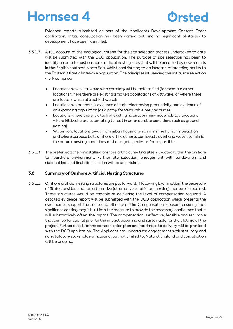
4.2.1.1 Above water deterrents (Figure 4) are usually fixed to buoys or markers attached to set
fishing gear, which works to scare birds away from fishing nets. Current nets are often made
from monofilament nylon, which is nearly invisible to seabirds underwater and so the aim of
deterrents is to deter birds from approaching the nets and becoming entangled. Deterrents
usually comprise a buoy with some sort of attachment, such as spinning objects or small
kites, to deter birds.
Page 34/55 Doc. No: A4.6.1
Ver. no. A
(Source: https://www.acap.aq/latest-news/3453-portugal-tests-a-scary-bird-device-to-reduce-incidental-catches-of-
seabirds-in-fishing-gear).
Figure 4: An above water deterrent
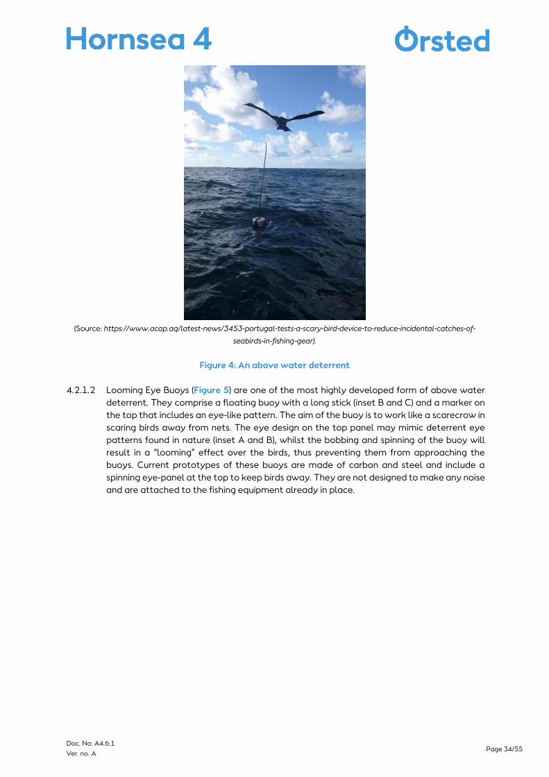
4.2.1.2 Looming Eye Buoys (Figure 5) are one of the most highly developed form of above water
deterrent. They comprise a floating buoy with a long stick (inset B and C) and a marker on
the top that includes an eye-like pattern. The aim of the buoy is to work like a scarecrow in
scaring birds away from nets. The eye design on the top panel may mimic deterrent eye
patterns found in nature (inset A and B), whilst the bobbing and spinning of the buoy will
result in a “looming” effect over the birds, thus preventing them from approaching the
buoys. Current prototypes of these buoys are made of carbon and steel and include a
spinning eye-panel at the top to keep birds away. They are not designed to make any noise
and are attached to the fishing equipment already in place.
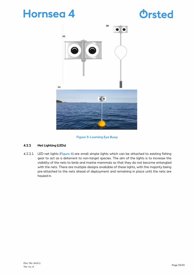
Page 35/55 Doc. No: A4.6.1
Ver. no. A
Figure 5: Looming Eye Buoy
4.2.2 Net Lighting (LEDs)
4.2.2.1 LED net lights (Figure 6) are small simple lights which can be attached to existing fishing
gear to act as a deterrent to non-target species. The aim of the lights is to increase the
visibility of the nets to birds and marine mammals so that they do not become entangled
with the nets. There are multiple designs available of these lights, with the majority being
pre-attached to the nets ahead of deployment and remaining in place until the nets are
hauled in.
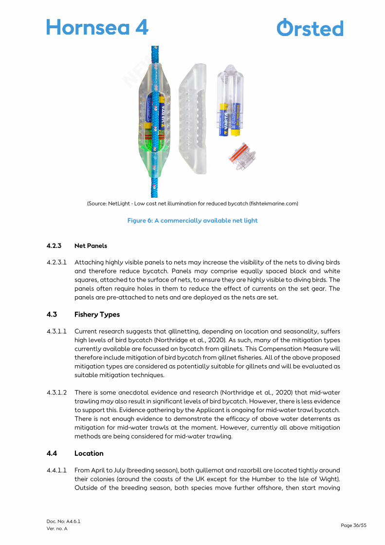
Page 36/55 Doc. No: A4.6.1
Ver. no. A
(Source: NetLight - Low cost net illumination for reduced bycatch (fishtekmarine.com)
Figure 6: A commercially available net light
4.2.3 Net Panels
4.2.3.1 Attaching highly visible panels to nets may increase the visibility of the nets to diving birds
and therefore reduce bycatch. Panels may comprise equally spaced black and white
squares, attached to the surface of nets, to ensure they are highly visible to diving birds. The
panels often require holes in them to reduce the effect of currents on the set gear. The
panels are pre-attached to nets and are deployed as the nets are set.
4.3 Fishery Types
4.3.1.1 Current research suggests that gillnetting, depending on location and seasonality, suffers
high levels of bird bycatch (Northridge et al., 2020). As such, many of the mitigation types
currently available are focussed on bycatch from gillnets. This Compensation Measure will
therefore include mitigation of bird bycatch from gillnet fisheries. All of the above proposed
mitigation types are considered as potentially suitable for gillnets and will be evaluated as
suitable mitigation techniques.
4.3.1.2 There is some anecdotal evidence and research (Northridge et al., 2020) that mid-water
trawling may also result in significant levels of bird bycatch. However, there is less evidence
to support this. Evidence gathering by the Applicant is ongoing for mid-water trawl bycatch.
There is not enough evidence to demonstrate the efficacy of above water deterrents as
mitigation for mid-water trawls at the moment. However, currently all above mitigation
methods are being considered for mid-water trawling.
4.4 Location
4.4.1.1 From April to July (breeding season), both guillemot and razorbill are located tightly around
their colonies (around the coasts of the UK except for the Humber to the Isle of Wight).
Outside of the breeding season, both species move further offshore, then start moving

Page 37/55 Doc. No: A4.6.1
Ver. no. A
south. By December both species are located offshore around all UK coasts. As seabird
distributions change throughout the year, it is likely that bycatch rates will also vary as
higher seabird densities increase the bycatch risk (Bradbury et al., 2017). It is therefore
important to evaluate temporal variations when identifying areas of high bycatch
vulnerability for the purpose of planning mitigation measure locations.
4.4.1.2 Potential fisheries with reported bird bycatch and population connectivity with the wider
site network and include the UK South coast, Cornwall, and the Thames Estuary. All of
these locations are being considered for potential mitigation trails and future
implementation.). Bycatch hotspots have been identified in both the South East and South
West of the UK, along with reports of bird bycatch at other locations along the south coast
and in the Thames Estuary. Site plans Figure 7 and Figure 8 show the areas where fishing
may take place and where mitigation trials may be targeted.
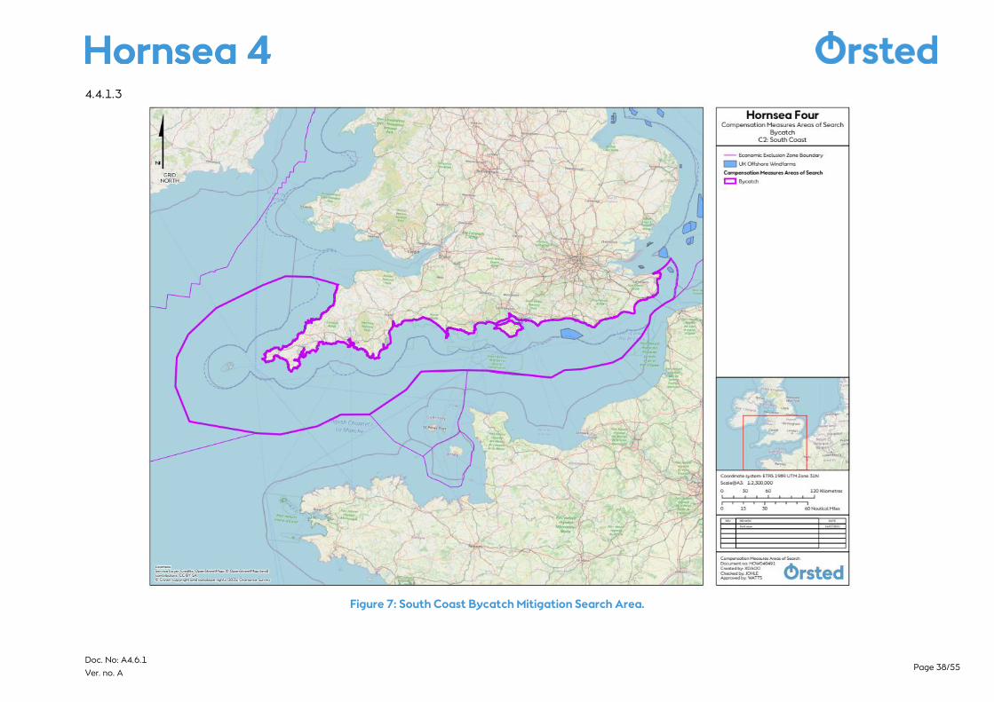
Page 38/55 Doc. No: A4.6.1
Ver. no. A
4.4.1.3
Figure 7: South Coast Bycatch Mitigation Search Area.
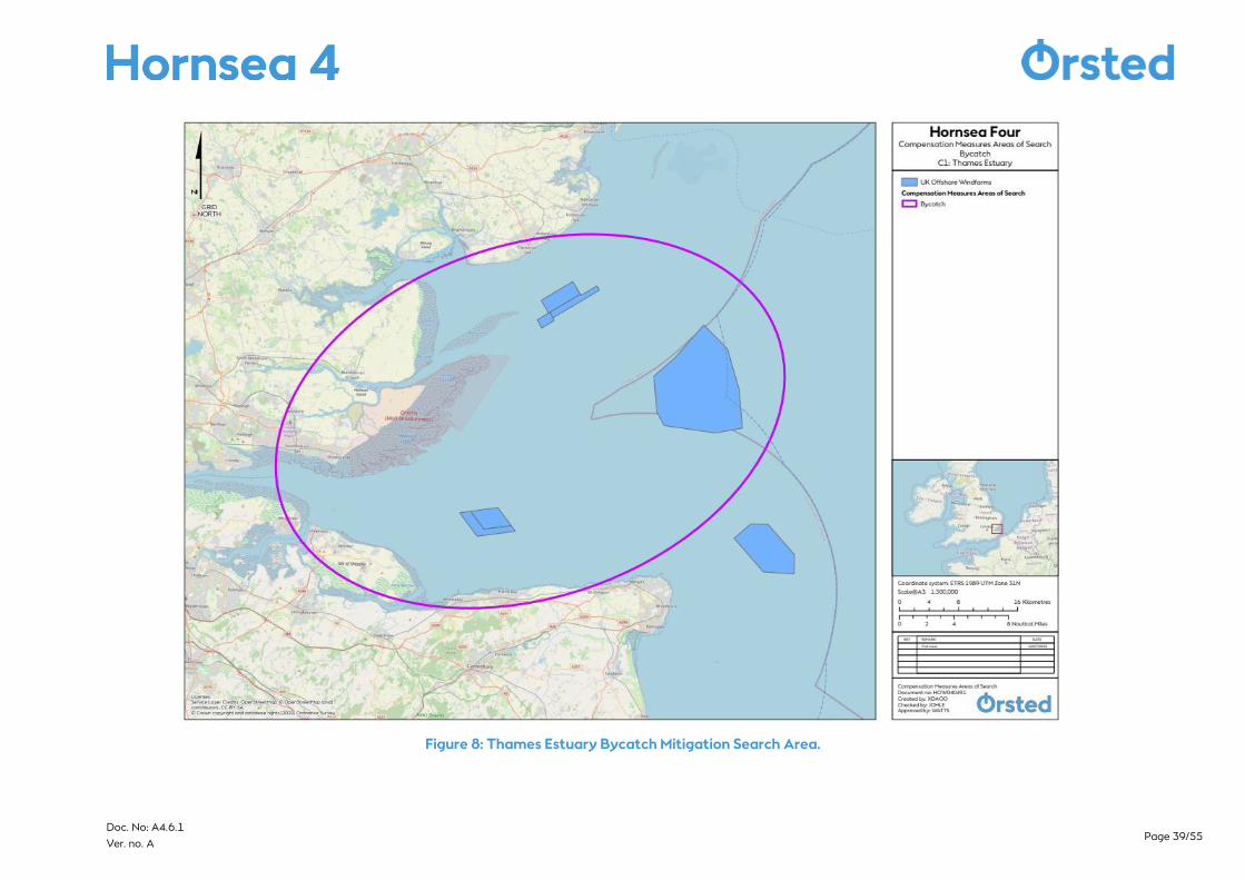
Page 39/55 Doc. No: A4.6.1
Ver. no. A
Figure 8: Thames Estuary Bycatch Mitigation Search Area.

Page 40/55 Doc. No: A4.6.1
Ver. no. A
4.5 Implementation, operation, and monitoring
4.5.1.1 Mitigation trails are planned for Autumn / Winter 2021. Following trials to gather further
evidence on the efficacy of each mitigation method, a specific measure or combination of
measures will be selected to take forward. Implementation of the planned mitigation will
begin following determination of the DCO application by the Secretary of State.
4.5.1.2 Work will be undertaken with local representatives and contacts within the target fishery
areas to ensure uptake of the mitigation equipment. Use of the equipment may need to be
incentivised to ensure uptake and continued usage.
4.5.1.3 To ensure that the equipment continues to be used and that further evidence can be
gathered to confirm the success of the measures, a monitoring programme may be required
during the operational use of the measures. There are many examples of fishing gear
monitoring around the world, which include but are not limited to gear cameras, self-
reporting, blue-tooth tags, and equipment trackers. The exact method of monitoring will be
decided based upon further evidence gathering and discussion with industry experts.
4.5.1.4 The Wind Farm is expected to operate for 35 years following construction. If required, the
accepted mitigation measure(s) would be used and monitored throughout the operational
lifespan of the Wind Farm. Following the monitoring programme, overall measure uptake
and success of the mitigation measure, the equipment may continue to be used as a
mitigation deterrent.
4.6 Other projects and trials
4.6.1.1 There are currently trials of mitigation measures planned around the UK by other
organisations. Exact details of these are not available, However the details currently known
to the Applicant are trials that may be undertaken in 2021 or 2022 in both Cornwall and
Scotland with the Looming Eye Buoy.
4.7 Summary of Bycatch Compensation Measure
4.7.1.1 Bycatch reduction is a primary Compensation Measure. In-combination with other primary
razorbill and guillemot measures, bycatch mitigation will be able to deliver the required
level of compensation for Hornsea Four. A detailed evidence report, and roadmap will be
submitted with the DCO application to demonstrate the potential compensation
deliverable by the bycatch mitigation both alone and combined with the other primary
Compensation Measures. The evidence report will include a summary of the supporting
evidence for bycatch compensation and the roadmap will outline the further steps that will
be undertaken from submission to demonstrate that the Compensation Measure can be
delivered. These Compensation Measures are effective, feasible and securable measures
that can be implemented prior to the impact occurring and sustainable for the lifetime of
the project. In designing this Compensation Measure the Applicant has consulted and
worked with academics, Natural England, the RSPB, fisheries representatives and other
relevant stakeholders to ensure this Compensation Measure is both robust and deliverable.
Page 41/55 Doc. No: A4.6.1
Ver. no. A
5 Predator Eradication
5.1 Introduction and Background
5.1.1.1 Seabirds encounter many factors which influence adult survival and breeding success.
These factors include (but are not limited to); predation (Craik 1997; Buchadas & Hof 2017),
climate change related shifts to prey availability (Gaston & Elliott 2014; Divoky et al., 2015)
and abundance and, fisheries practices (Furness & Tasker 2000; Frederiksen et al., 2004).
Other factors may also include seabird bycatch (Miles et al., 2020) and plastic pollution
(O’Hanlon et al., 2017).
5.1.1.2 Colony population and nest surveys are undertaken to assess the overall adult breeding
population and breeding success of a colony which can be consequently linked to external
factors influencing a population (Gjerdrum et al., 2003). Predation of seabird eggs, nestlings
and adult birds may be one such influencing factor. For example, guillemot and razorbill
have been shown to be vulnerable to numerous species of predator.
5.1.1.3 Seabirds have several natural predators distributed across their range. Natural predators
generally pose a low risk to breeding seabirds as they have coevolved with predation
pressure and have mechanisms or behaviours to avoid or withstand it. For example, many
seabirds choose to nest on remote islands which are free from ground dwelling predators.
5.1.1.4 When non-native predators are introduced to these island colonies, they may have
profound impacts on the native fauna (Jones et al., 2016; Thomas et al., 2017). Many
offshore islands around the UK have established populations of invasive mammals,
originating from mainland Britain or from further afield (stow away on ships etc) (Stanbury
et al., 2017).
5.1.1.5 Rats are among the most common and invasive species impacting native wildlife worldwide
through predation, competition of resources and modification of habitat (Jones et al., 2008).
Previous estimates of the prevalence of rats have indicated more than 80% of islands
globally support a rat population (Atkinson, 1985). Rat is the general term used to describe
the various species within the genus Rattus. Of the large number of species in this genus
throughout the world, the key species in a UK context are the brown rat (also referred to as
the Norwegian rat) (Rattus norvegicus) and the black rat (commonly referred to as the ship
rat) (Rattus rattus).
5.1.1.6 Both brown and black rats are known predators of many small-bodied seabird species,
however, when available, the majority of predation is focused on eggs and chicks (Atkinson,
1985). This is particularly relevant when rats are concentrated around coastal zones during
the breeding season (Main et al., 2019), with the predation focus on eggs and chicks having
been evidenced through numerous monitoring methods, including stable isotope analysis
extracted from rat tissues (Stapp, 2002).
5.1.1.7 Rats are known to impact guillemot and razorbill colonies (e.g. Swann, 2002; Mavor et al.,
2004; Russel, 2011) especially those breeding on islands (Thomas et al., 2017). For example,
prior to their eradication in 2005/2006, black rats were associated with the population
declines of the 13,000 pairs of nesting guillemot and 11,000 pairs of nesting razorbill on the
Shiant Isles (Scotland) due to the predation of eggs and chicks (Swann, 2002).
5.1.1.8 At Canna Island, Scotland, brown rats were responsible for the predation of auk eggs
(Russell, 2011) and the redistribution of nesting guillemot into areas which were inaccessible
Page 42/55 Doc. No: A4.6.1
Ver. no. A
to rats (Mavor et al., 2004). This prompted the initiation of an island wide rat eradication
scheme in 2006. Both brown and black rat have been recorded at multiple other UK
colonies (Lockley, 1953; Harris, 1984; Lovegrove et al., 1994). Rats present at guillemot and
razorbill colonies have therefore formed the focus of location searches for eradication
schemes. Despite this focus, other predators will also be considered if information comes to
light of a pressure to guillemot and razorbill populations.
5.2 Proposals for Hornsea Four
5.2.1.1 To compensate the potential displacement impact on guillemot and razorbill from the
operation of the Hornsea Four Wind Farm, The Applicant proposes to implement a predator
eradication programme at selected guillemot and/ or razorbill breeding colonies. The
selected colony will be chosen based on delivery and connectivity to the populations within
the wider site network. This would be part of a package of compensation measures for
these species.
5.2.1.2 Predator eradication will be undertaken using well established methods evidenced
throughout the wealth of previous predator eradication examples from the UK and further
afield. For ground predators, such as rats, this usually involves poison bait stations. The
primary species the measures of predator eradication would be focussed upon are rat and
house mouse but could extend to include mink or crow as a supportive measure pending
ecological advice and stakeholder discussions, whilst ensuring non-targeted species are
accidently eradicated.
5.2.1.3 Following the removal of the invasive species, biosecurity measures will subsequently be
installed to prevent re-invasion. Biosecurity measures form a vital consideration in ensuring
that efforts to remove invasive species have not be undertaken in vain. There are a
significant number of biosecurity measures available depending on the location and species
being considered, all of which have been tried and tested at previous predator eradication
schemes (i.e., Biosecurity for LIFE project3).
5.3 Location
5.3.1.1 It is proposed that predator eradication will be undertaken on an island or islands where
both invasive mammalian predators and guillemot and/ or razorbill are present. The
Applicant is currently liaising with site managers at multiple islands to understand the
prevalence of invasive mammalian species and ascertain the level of pressure posed to
breeding guillemot and razorbill. The potential broad areas currently being considered for
predator eradictaion include:
▪ Rathlin Island;
▪ Channel Islands;
▪ Isles of Scilly; and
▪ Islands off the south coast of Devon.
5.3.1.2 The specific locations within these broad areas (see Figure 1) are continuing to be explored
and The Applicant will remain open to considering other locations if identified and/or
deemed suitable. Those islands where invasive mammalian predators have increased
access to breeding locations will be favoured due to the high degree of overlap.
3 https://biosecurityforlife.org.uk/

Page 43/55 Doc. No: A4.6.1
Ver. no. A
5.3.1.3 Before any predator eradication schemes are implemented at a specific location, an
eradication feasibility assessment will be undertaken to ensure measures can be employed
to remove the invasive species and that biosecurity measures can be subsequently installed
to prevent reinvasion, whilst not affecting the native species and/or species that may not
affect guillemot and/or razorbills.
5.4 Operation, implementation, and monitoring
5.4.1.1 The objective of the eradication programme will be to remove mammalian predators from
the island(s) that are currently suppressing the breeding success (and therefore, population
size) of guillemot and razorbill (amongst other species) at these locations. The removal of
this pressure will therefore lead to an increase in productivity and ultimately an increase in
the population size of these species, whilst not affecting any other species that are not
known to be detrimental to guillemot and/or razorbills.
5.4.1.2 Following the feasibility assessment and in partnership with site managers, invasive species
eradication specialists will be contracted to undertake the island(s) eradication.
Consideration of the timing of a predator eradication programme will be made to ensure
that they are undertake at the optimal time and that will not for example affect a
species/habitat that are not known to be detrimental to guillemot and/or razorbills.
5.4.1.3 The primary aim of an eradication scheme is always to completely remove the introduced
animal from the chosen area. In theory, just a single pregnant female of the invasive animal
could repopulate the area. Two years intensive monitoring for the presence of the
eradicated animal is required to receive the invasive-free status (Nathan et al., 2015; Russell
et al., 2017). For example, this was the process taken for the eradication of rats on Canna
and Sanday under contract by Wildlife Management International, starting in late 2005. By
February 2006 the last rat sign was detected, and after a two-year period of intensive
monitoring, the island was declared rat-free in 2008 (see Bell, et al., 2011). The predator
eradication programme would only be undertaken by appropriate qualified people and all
methods will be agreed with the appropriate stakeholders.
5.4.1.4 Following the invasive species status, seabird recovery monitoring will continue for the
lifetime of Hornsea Four. Monitoring will include population census and productivity
monitoring. This will be compared to pre-eradication data (which will be collected to
characterise the baseline and supplement historic seabird data for the location where
available). The presence of invasive species will also be monitored to detect signs of
repopulation.
5.5 Summary of Predator Eradication Compensation Measure
5.5.1.1 Predator eradication is a primary Compensation Measure. In-combination with other
primary razorbill and guillemot measures, predator eradication will be able to deliver the
required level of compensation for Hornsea Four. A detailed evidence report, and roadmap
will be submitted with the DCO application to demonstrate the potential compensation
deliverable by the predator eradication programme both alone and combined with the
other primary compensation measures. The evidence report will include a summary of the
supporting evidence for predator eradication compensation and the roadmap will outline
the further steps that will be undertaken from submission to demonstrate that the
Compensation Measure can be secured. These Compensation Measures are effective,
feasible and securable measures that can be implemented prior to the impact occurring
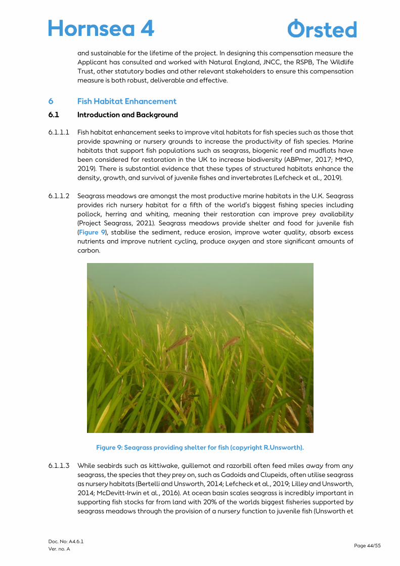
Page 44/55 Doc. No: A4.6.1
Ver. no. A
and sustainable for the lifetime of the project. In designing this compensation measure the
Applicant has consulted and worked with Natural England, JNCC, the RSPB, The Wildlife
Trust, other statutory bodies and other relevant stakeholders to ensure this compensation
measure is both robust, deliverable and effective.
6 Fish Habitat Enhancement
6.1 Introduction and Background
6.1.1.1 Fish habitat enhancement seeks to improve vital habitats for fish species such as those that
provide spawning or nursery grounds to increase the productivity of fish species. Marine
habitats that support fish populations such as seagrass, biogenic reef and mudflats have
been considered for restoration in the UK to increase biodiversity (ABPmer, 2017; MMO,
2019). There is substantial evidence that these types of structured habitats enhance the
density, growth, and survival of juvenile fishes and invertebrates (Lefcheck et al., 2019).
6.1.1.2 Seagrass meadows are amongst the most productive marine habitats in the U.K. Seagrass
provides rich nursery habitat for a fifth of the world’s biggest fishing species including
pollock, herring and whiting, meaning their restoration can improve prey availability
(Project Seagrass, 2021). Seagrass meadows provide shelter and food for juvenile fish
(Figure 9), stabilise the sediment, reduce erosion, improve water quality, absorb excess
nutrients and improve nutrient cycling, produce oxygen and store significant amounts of
carbon.
Figure 9: Seagrass providing shelter for fish (copyright R.Unsworth).
6.1.1.3 While seabirds such as kittiwake, guillemot and razorbill often feed miles away from any
seagrass, the species that they prey on, such as Gadoids and Clupeids, often utilise seagrass
as nursery habitats (Bertelli and Unsworth, 2014; Lefcheck et al., 2019; Lilley and Unsworth,
2014; McDevitt-Irwin et al., 2016). At ocean basin scales seagrass is incredibly important in
supporting fish stocks far from land with 20% of the worlds biggest fisheries supported by
seagrass meadows through the provision of a nursery function to juvenile fish (Unsworth et
Page 45/55 Doc. No: A4.6.1
Ver. no. A
al. 2019b). A high abundance of juvenile herring were found in seagrass in studies that took
place in the United Kingdom, Denmark and the Baltic Sea (Bertelli and Unsworth, 2014;
Polte and Asmus, 2006; Rönnbäck et al., 2007). Where seagrass meadows decline, there is
evidence that this has negative effects on pelagic fish stocks (Kritzer et al. 2016; Seitz et al.
2013). This in turn, may impact the success of the species that feed on them.
6.2 The importance of seagrass
6.2.1.1 In England, seagrass is protected as an Annex 1 feature under the EU Habitats Directive,
protected in designated Special Areas of Conservation and as a feature of Sites of Special
Scientific Interest (SSSIs). Seagrass beds are also listed as Features of Conservation Interest
(FOCI) in Marine Conservation Zones (MCZs). Seagrass beds (Z. marina and Z. noltei) are listed
as a Priority Habitat derived from Section 41 of the Natural Environment and Rural
Communities (NERC) Act 2006.
6.2.1.2 Seagrass meadows are one of the world's most threatened ecosystems and are rapidly
declining (Waycott et al., 2009). Factors affecting seagrass meadows and contributing to
the decline include wasting disease, pollution and physical disturbance. In the UK, seagrass
loss has been catastrophic and is estimated to have declined by 85% since the 1920s
(Hiscock et al., 2005, Unsworth et al., 2019) and total UK losses could be as high as 92%
(Green et al., 2021). Of the 155 estuaries in Britain, only 20 estuaries support seagrass and
many are in poor condition and facing continued decline (Jones and Unsworth, 2016;
Unsworth et al., 2017a,b; Unsworth et al., 2019). It is estimated that 39% of seagrass in the
UK has been lost since the 1980’s (Green et al., 2021). In the context of seabirds in the North
Sea there is very good evidence that seagrass has mostly disappeared from the coastline
between Lindisfarne in the NE and Scolt head in Norfolk, a gap in straight line distance of
almost 350km. Seabirds in that area no longer have access to resources within seagrass or
supported by seagrass, with seagrass formerly in the Humber, the Tyne, the Tees and the
Wash all but gone (Green et al. 2021; Unsworth, 2021).
6.2.1.3 The recognition of the importance and threats to seagrass has led to a number of trials
around the UK and globally. Research has come a long way since the early trials in the
1970’s in East Anglia which were unsuccessful. With the knowledge of the requirements for
seagrass, restoration has been successful in many plantings and meadows have often come
to perform much as naturally propagated meadows (Fonseca et al. 1985; Fonseca et al.
1996). In the UK researchers are seeing success from restoration trials planted in 2018 and
will soon see the results of pilot projects deployed in 2020 and 2021 (Unsworth, 2021).
6.2.1.4 Through the Applicants work on the Environmental Impact Assessment and Habitats
Regulations Assessment, the Applicant has been exploring opportunities to restore
seagrass to support a range of ecosystems services and associated research, as a potential
compensation measure. The Applicant recognises the importance of seagrass as a measure
that can provide resilience to other compensation measures such as predator eradication,
habitat management, bycatch mitigation and provision of artificial nesting. The Applicant
proposes to provide a package of measures that will support the seabird populations such
as kittiwake, guillemot and razorbill locally and in the North Sea. The measures will be
designed to seek opportunities to be spatially co-located to maximise the benefits of the
measures and located to ensure the overall coherence of the network is maintained. The
Applicant is exploring a number of different fish habitats for enhancement such as mudflats,
saltmarsh and reef. Recognising the importance of seagrass to fish populations and seabirds
we are currently focusing on the opportunities for potential seagrass restoration projects.
Page 46/55 Doc. No: A4.6.1
Ver. no. A
6.3 Seagrass Restoration Projects
6.3.1.1 Seagrass restoration projects have been undertaken for over 50 years (MMO, 2019). For
example, in Chesapeake Bay in the US, 3000 hectares of seagrass have been restored since
the first survey in 1984 from once lifeless habitats, with rapid recovery of their ecosystem
services now being observed (Orth et al. 2020). The restored seagrass meadows in
Chesapeake Bay have recorded rapidly increasing ecosystem service provision from
maturing restored seagrass meadows that have become indistinguishable from natural
meadows (Orth et al. 2020).
6.3.1.2 In recent years a number of seagrass restoration projects have been undertaken in the UK.
Project Seagrass and Swansea University led the UK’s first major restoration project in Dale
in West Wales. Although many aspects of this project have resulted in learning lessons, the
overall project is considered a resounding success. In 2013, Swansea University commenced
a programme of restoration work, studies on laboratory grown plants, transplantations and
the movement of ‘seagrass sods’ were conducted alongside studies using seeds. This led to
a range of trials utilising seagrass seeds planted in small hessian bags, a method that to
date has been very successful in further studies in West Wales (Unsworth et al. 2019). The
use of hessian seed bags helps to overcome the negative feedbacks caused by Green Shore
crabs, unstable sediments and tidal loss of seeds (Maxwell et al. 2017). In 2020, over a
million seagrass seeds were planted into Dale Bay in West Wales using the hessian seed
bag method, over the coming 12 months and years these are expected to germinate and
lead the development of the UK’s first major seagrass restoration planting.
6.3.1.3 Seagrass meadows in the Humber Estuary have declined dramatically since the 1930’s
(Philip, 1936). The Humber Estuary is an important fish spawning area for sandeel, lemon
and dover sole and important nursery area for plaice, herring, flounder and sprat (Rogers et
al., 1998). Many of these species are prey for seabirds in the North Sea including kittiwake,
guillemot and razorbill. Organisations are undertaking research and trials to expand the
remaining 20ha of seagrass at Spurn Point Nature Reserve. Yorkshire Wildlife Trust are
undertaking trials to discover the optimal conditions for gathering and germinating
seagrass seeds (Yorkshire Wildlife Trust, 2021).
6.3.1.4 In Plymouth Sound and the Solent, the largest restoration project began in April 2021, a
partnership project led by Ocean Conservation Trust (OCT) and involving Natural England,
and numerous other stakeholders and volunteers (OCT, 2021). The project aims to plant
seagrass bags across a total of eight hectares of seagrass meadows – four hectares in
Plymouth Sound and four hectares in the Solent Maritime Special Area of Conservation. By
planting seagrass, the project hopes to create more seagrass meadows which provide
homes for juvenile fish and protected creatures like seahorses and stalked jellyfish (OCT,
2021).
6.3.1.5 The Applicant is exploring opportunities to expand existing seagrass restoration projects
that are already underway and opportunities to create new projects with the academic
community that could potentially form a resilience compensation measure, these broad
locations are illustrated in Figure 1.

Page 47/55 Doc. No: A4.6.1
Ver. no. A
6.4 Seagrass Restoration Techniques
6.4.1.1 Seagrass restoration has been formally conducted for over 50 years and the means of doing
this can principally be split into two major techniques:
▪ replanting; and
▪ reseeding.
6.4.1.2 Both techniques have their relative merits and have exhibited varying levels of success.
Reseeding and replanting techniques have sometimes been used together. Using seeds
possibly in conjunction with adult plants, may in some instances prove more effective (van
Katwijk et al. 2016). A broad overview of the literature illustrates that although a lot is now
known about seagrass restoration, there are research gaps and as a result the success rate
of restoration projects can vary, demonstrating that it is vital that studies are undertaken
to assess the feasibility and site selection and ensure the efficacy of the measure (Unsworth
& Butterworth, 2021).
6.4.1.3 The use of reseeding generally relates to the collection and targeted redistribution (and
sometimes processing) of wild seed. Adult shoot replanting normally involves harvesting
plants from an existing meadow and transplanting them to the restoration site. The
reproductive fronds of wild seed is collected by hand by SCUBA divers. The seeds collected
by recent projects have obtained permits/consent from Natural England and Natural
Resources Wales. Recent reports from the Environment Agency highlight the need for
seagrass restoration to increasingly depend upon nursery grown propagules.
6.4.1.4 In most cases, shoot planting involves some means of anchoring the shoots to the bottom
until the roots can take hold (root into the bottom). Replanting may use either weighted
and anchored hessian sacks or mechanistic approaches, similar to tree planting, to plant
various sizes and ages of seagrass plants into existing areas of seagrass, with the later
technique favoured for areas of intertidal seagrass. Planting of seedlings may also be
undertaken by divers who are transported to the site by boat. Seeds can also be directly
deployed from the boat and often hessian bags are used to help anchor the seeds in place
during germination. It is expected that up to two vessels would be required for the seagrass
restoration at each location.
6.4.1.5 Seagrass restoration requires consideration of a range of factors necessary to make it a
success. A recent review of the success of restoration projects globally found that success
relates to the severity of the habitat degradation (van Katwijk et al. 2016). Seeds, adult
plants and sods are not significantly different, although seedlings show lower success rates.
A short distance to the donor site is also related to success.
6.4.1.6 Some seagrass restoration projects particularly the trials of small/medium sized projects
have funding secured. The Applicant will look to fund additional areas for seagrass
restoration that do not currently have funding secured and therefore provide additional
benefit rather than projects that are part of normal practice and site/habitat management
of the designated sites. Evidence gathering by the Applicant is ongoing and discussions with
stakeholders on restoration projects and techniques is continuing. However, currently all
types of restoration methods are being considered and may be combined using the best
techniques at the time of restoration for the greatest success.
Page 48/55 Doc. No: A4.6.1
Ver. no. A
6.5 Location
6.5.1.1 Exploration of potential broad areas for seagrass restoration is ongoing. The main areas
that are being considered consistently support all of the target seabird species and
therefore provide options for seagrass restoration as well as supporting other
compensation measures.
6.5.1.2 From April to July (breeding season), both guillemot and razorbill are located tightly around
their colonies (around the coasts of the UK except for the Humber to the Isle of Wight).
Outside of the breeding season, both species move further offshore, then start moving
south. By December both species are located offshore around all UK coasts. As seabird
distributions change throughout the year, the composition of their prey can also change,
for example guillemot have a more varied diet in winter (Furness and Tasker, 2000). It will
therefore be important to evaluate temporal variations when undertaking site selection
analysis for the purpose of planning compensation measure locations.
6.5.1.3 Potential existing seagrass meadows located within proximity to the primary razorbill and
guillemot compensation measures i.e. bycatch and predator eradication, with reported
connectivity with the wider site network and the North Sea populations include the Solent,
Channel Islands, Cornwall, Isles of Scilly, Essex Estuaries, Rathlin Island and Humber Estuary
(see Figure 1). All of these locations are being considered for potential feasibility trails and
future implementation.
6.6 Implementation, operation, and monitoring
6.6.1.1 Prior to any field studies commencing, detailed feasibility studies will be undertaken to
assess the physical parameters for seagrass to be restored and undertake further
stakeholder engagement. The Applicant recognise the need for feasibility studies to
consider site selection and methodology to increase the likelihood of a successful
restoration programme and efficacy of the compensation measure. Factors that will be
considered prior to restoration efforts being initiated to ensure the viability of seagrass
restoration include looking for sites:
▪ being sheltered from wave action;
▪ with suitable topographical and hydromorphological conditions including
sedimentation rates;
▪ sufficient nutrients and available light;
▪ good water quality; and
▪ avoid sites with activities that could cause significant physical disturbance.
6.6.1.2 Surveys may be required to establish the levels of activity at the potential locations.
Planting seagrass at sites previously known to support seagrass and known to have
appropriate conditions for seagrass would likely result in increased biodiversity and
ecosystem service provision (Unsworth, 2021). Part of the site selection process will take
evidence of previous seagrass locations as a key consideration (Green et al., 2021).
6.6.1.3 For a new restoration project, we may conduct physical surveys (e.g. particle size, depth,
slope, light, temp, total suspended solids, redox layer) and biological surveys as well as
habitat mapping at each site, these could involve the use of camera drops and diver surveys
to assess the suitability of the potential locations. When undertaking site selection studies,
we will examine the health and nutrient status of the closest seagrass meadows or patch.

Page 49/55 Doc. No: A4.6.1
Ver. no. A
6.6.1.4 It may be necessary, especially with the potential scale restoration, that a series of surveys
will be needed to identify potential seagrass meadows for future seed collections. This will
be conducted in consultation with Natural England and other stakeholders. When planning
the restoration project, we will focus on facilitating natural recovery through alleviating
recruitment limitation.
6.6.1.5 The Applicant will undertake studies to understand the most appropriate scale for any
resilience measure and consider how to maximise the benefits of spatial overlap/proximity
to the other compensation measures. We recognise the importance of encouraging long-
term survival by promoting self-facilitation through implementation at a large-enough
scale. We will ensure that significant contingency, which may include reseeding/replanting,
is built into the measure to provide the necessary confidence that it will have sufficient
resilience, offset the impact and efficacy as a compensation measure.
6.6.1.6 Engagement with statutory and non-statutory bodies and local stakeholders and
landowners will be undertaken to share and discuss our ambitions, plans and to ensure the
success of the measures. We will work with academics and organisations with experience
of previous restoration projects in order to ensure that activities build on the outcomes of
best practice and lessons learnt.
6.6.1.7 Following the site suitability surveys a site selection process (potentially using a decision
matrix) will be used to select the optimal site(s) for restoration. Environmental baseline
surveys of the site(s) will be undertaken so that change over time can be assessed
accordingly. Restoration of the seagrass using replanting and/ or reseeding methods will be
undertaken following the methodology devised through engagement with academics and
stakeholders. A pilot trial planting scheme is likely to be undertaken particularly for any
new restoration location. Following the feasibility trials to gather further evidence on the
efficacy of the seagrass restoration, the sites and methods will be selected to take forward.
6.6.1.8 There are many restoration projects being considered by a number of organisations in the
UK and it may be that a project has already undertaken the required site selection and trials
but is looking for the resource to undertake a larger scale scheme. The Applicant will discuss
these options with academics and stakeholders as it may be that a suitable project is
already underway that The Applicant could contribute towards to enable or expand the
restoration project. Implementation of the planned compensation measure will begin
following determination of the DCO application by the Secretary of State if required. All
necessary permissions and consents will be obtained.
6.6.1.9 It is recognised that there are knowledge gaps on the specific linkages between seagrass in
the UK and non-grazing seabirds and the level of the role of seagrass supporting forage fish
for seabirds such as razorbill, guillemot and kittiwake. Whilst the broad understanding of
the links between seagrass meadows and fisheries are well understood (Kritzer et al. 2016;
Unsworth et al. 2019b), we still have limited evidence for this role at a UK level, with most
data collected from only a handful of sites (Bertelli and Unsworth 2014; Peters et al. 2014).
Understanding about temporal and spatial variability is particularly lacking (Unsworth &
Butterworth, 2021). Whilst we know that forage fish species clupeids, gadoids and sand eels
all utilise UK seagrass meadows at periods of the life cycle the nature of this role hasn’t
been quantified (Unsworth & Butterworth, 2021).
Page 50/55 Doc. No: A4.6.1
Ver. no. A
6.6.1.10 A key component of the fish habitat enhancement compensation measure will be research,
to gather evidence to contribute towards filling these knowledge gaps. We have identified
a number of initial potential research projects (in addition to feasibility studies) that the
research could cover including:
▪ Foraging seagrass habitat study for seabirds including species counts, behavioural
observations and habitat mapping;
▪ Fish surveys within seagrass meadows using seine and/or fyke netting;
▪ Further seabird diet studies; and
▪ Migratory fish tagging to understand fish movements.
▪ These potential research topics will be explored in greater detail and a research
programme will be devised to support of the measures.
6.6.1.11 Hornsea Four is expected to operate for 35 years following construction. Monitoring of
restoration will be essential to demonstrate the efficacy of the compensation measure and
if required, the seagrass meadow would be monitored throughout the operational lifespan
of the Hornsea Four. The exact method of monitoring will be decided based upon further
evidence gathering and discussion with restoration experts and stakeholders. A Monitoring
programme will be developed and at key stages the results of the restoration will be shared
to improve the knowledge and evidence for seagrass restoration.
6.6.1.12 Adaptive management is an iterative process which combines management measures and
subsequent monitoring with the aim of improving effectiveness whilst also updating
knowledge and improving decision making over time. Adaptive management will be an
important component of the compensation measure and will be used as a method to
address unforeseen issues or deviations from expected time scales (i.e. additional infill
planting required).
6.7 Summary of Fish Habitat Enhancement Compensation Measure
6.7.1.1 Fish habitat enhancement and in particular seagrass restoration is considered as a
compensation measure to support the resilience of the other compensation measures to
form a package of measures. In-combination with other kittiwake, razorbill and guillemot
measures, predator eradication will be able to deliver the required level of compensation
for Hornsea Four. A detailed evidence report, and roadmap will be submitted with the DCO
application to demonstrate the potential compensation deliverable by the fish habitat
enhancement both alone and combined with the other primary compensation measures.
The evidence report will include a summary of the supporting evidence for fish habitat
enhancement and the roadmap will outline the further steps that will be undertaken from
submission to secure this compensation measure. The package of compensation measures
is considered effective, feasible and securable measures that can be implemented prior to
the impact occurring and sustainable for the life-time of the project. In designing this
compensation measure the Applicant has consulted and worked with academics, Natural
England, JNCC, the RSPB, The Wildlife Trust, other statutory bodies and other relevant
stakeholders to ensure this compensation measure is both robust and deliverable.

Page 51/55 Doc. No: A4.6.1
Ver. no. A
7 References
7.1 Introduction
APEM, (2021) Proof of Concept (PoC) aerial survey of offshore structure. Report to Hornsea Four.
Niras, (2021) Boat-based survey of oil and gad structures in the southern North Sea. Report to
Hornsea Four.
7.2 Kittiwake nesting
Babcock, M., Aitken, D., Lloyd, I., Wischnewski, S., Baker, R., Duffield, H., and Barratt, A. (2018)
Flamborough and Filey Coast SPA Seabird Monitoring Programme 2018. RSPB, Sandy.
Camphuysen, C. J., & de Vreeze, F. (2005). Black-legged Kittiwakes nesting on an offshore
platform in the Netherlands. Limosa 78, 65–74.
Camphuysen, C,J, & Leopold, M. M. F. (2007). Drieteenmeeuw vestigt zich op meerdere
platforms in Nederlandse wateren. Limosa 80, 153–156.
Christensen-Dalsgaard, S., Langset, M., Anker-Nilssen, T. (2019). Offshore oil platforms – a
breeding refuge for Norwegian Black-legged Kittiwakes Rissa tridactyla. Seabird 32, 20-32.
Coulson, J.C. (2011). The Kittiwake. T. & A.D. Poyser, London.
Daunt, F., Benvenuti, S., Harris, M.P., Dall Antonia, L., Elston, D.A. and Wanless, S., 2002.
Foraging strategies of the black-legged kittiwake Rissa tridactyla at a North Sea colony:
evidence for a maximum foraging range. Marine Ecology Progress Series, 245, 239-247.
Harris, S.M., Descamps, S., Sneddon, L.U., Bertrand, P., Chastel, O. and Patrick, S.C. (2020)
Personality predicts foraging site fidelity and trip repeatability in a marine predator. J. Anim.
Ecol. 89, 68–79.
Hatch S.A., Roberts B.D. and Fadely B.S. (1993). Adult survival of Black-legged Kittiwakes
Rissa tridactyla in a Pacific colony. Ibis 135, 247–254.
Horswill, C. and Robinson, R.A. (2015). Review of seabird demographic rates and density
dependence. JNCC Report No. 552. JNCC, Peterborough.
International Association of Marine Aids to Navigation and Lighthouse Authorities (2013) available
online at: R0139-The-Marking-of-Man-Made-Offshore-Structures-O-139-Ed2.1-December-2013-
1.pdf
Lewis, S., Sherratt, T.N., Hamer, K.C. & Wanless, S. (2001). Evidence of intra-specific
competition for food in a pelagic seabird. Nature, 412, 816–819.
Lewis, S., Wanless, S., Wright, P.J., Harris, M.P., Bull, J. & Elston, D.A. (2001). Diet and breeding
performance of black-legged kittiwakes Rissa tridactyla at a North Sea colony. Marine Ecology
Progress Series, 221, 277–284
Page 52/55 Doc. No: A4.6.1
Ver. no. A
Turner, D.M. (2010). Counts and breeding success of Blacklegged Kittiwakes Rissa tridactyla
nesting on man-made structures along the River Tyne, Northeast England, 1994–2009.
Seabird 23, 111–126.
Walsh, P.M., Halley, D.J., Harris, M.P., del Nevo, A., Sim, I.M.W., & Tasker, M.L. (1995). Seabird
monitoring handbook for Britain and Ireland. JNCC / RSPB / ITE / Seabird Group, Peterborough.
Woodward, I., Thaxter, C.B., Owen, E. and Cook, A.S.C.P. (2019). Desk-based revision of seabird
foraging ranges used for HRA screening. Report of work carried out by the British Trust for
Ornithology on behalf of NIRAS and The Crown Estate. BTO Research Report No. 724.
Thetford, Norfolk.
7.3 Predator eradication
Atkinson, I.A.E. 1985. ‘The Spread of Commensal Species of Rattus to Oceanic Islands and their
Effects on Island Avifaunas’. In: P.J. Moors (ed.) Conservation of Island Birds, pp. 35–81. ICBP
Technical Publication 3. Cambridge, UK: BirdLife International.
Bell, E., Boyle, D., Floyd, K., Garner-Richards, P., Swann, B., Luxmoore, R., Patterson, A., and
Thomas, R. 2011. ‘The groundbased eradication of Norway rats (Rattus norvegicus) from the Isle of
Canna, Inner Hebrides, Scotland’. In: C.R. Veitch, M.N. Clout and D.R. Towns (eds.) Island invasives:
eradication and management, pp. 269 –274. Occassional Paper SSC no. 42. Gland, Switzerland:
IUCN and Auckland, New Zealand: CBB.
Buchadas, A. R. C. & Hof, A. R. 2017. Future breeding and foraging sites of a southern edge
population of the locally endangered Black Guillemot Cepphus grylle. Bird Study 64: 306–316.
Craik, C. 1997. Long-term effects of North American Mink Mustela vison on seabirds in western
Scotland. Bird Study 44: 303–309.
Divoky, G. J., Lukacs, P. M. & Druckenmiller, M. L. 2015. Effects of recent decreases in Arctic sea ice
on an ice-associated marine bird. Progress in Oceanography 136: 151–161.
Frederiksen, M., Wanless, S., Harris, M. P., Rothery, P. & Wilson, L. J. 2004. The role of industrial
fisheries and oceanographic change in the decline of North Sea black-legged kittiwakes. Journal of
Applied Ecology, 41, 1129–1139.
Furness, R. & Tasker, M. 2000. Seabird-fishery interactions: quantifying the sensitivity of seabirds to
reductions in sandeel abundance, and identification of key areas for sensitive seabirds in the North
Sea. Marine Ecology Progress Series, 202, 253–264.
Gaston, A.J. & Elliott, K.H. 2014. Seabird diet changes in northern Hudson Bay, 1981-2013, reflect
the availability of schooling prey. Marine Ecology Progress Series, 513, 211-223.
Gjerdrum, C., Vallée, A. M. J., St Clair, C. C., Bertram, D. F., Ryder, J. L. & Blackburn, G. S. 2003.
Tufted puffin reproduction reveals ocean climate variability. Proceedings of the National Academy
of sciences of the United States of America 100: 9377–9382.Gsell, A.C., Seabrook-Davison, M.N.H.
& Brunton, D.H. 2014. Are wild rodents attracted to lure laboratory rats? Pacific Conservation
Biology, 20, 108–115.
Harris, M.P. 1984. The Puffin. T. & A.D. Poyser, Calton, UK.

Page 53/55 Doc. No: A4.6.1
Ver. no. A
Jones, H.P., Holmes, N.D., Butchart, S.H., Tershy, B.R., Kappes, P.J., Corkery, I., Aguirre-Muñoz, A.,
Armstrong, D.P., Bonnaud, E., Burbidge, A.A. and Campbell, K., 2016. Invasive mammal eradication
on islands results in substantial conservation gains. Proceedings of the National Academy of
Sciences, 113(15), pp.4033-4038.
Jones, H.P., Tershy, B.R., Zavaleta, E.S., Croll, D.A., Keitt, B.S., Finkelstein, M.E. & Howald, G.R. 2008.
Severity of the effects of invasive rats on seabirds: A global review. Conservation Biology, 22, 16–
26.
Lockley, R.M. (1953). Puffins. Devin-Adair, New York, NY.
Lovegrove, K., Williams, G. & Williams, I. 1994. Birds in Wales. T. & A.D. Poyser, London, UK.
Main, C.E., Bell, E., Floyd, K., Tayton, J., Ibbotson, J., Whittington, W., Taylor, P.R., Reid, R., Varnham,
K., Churchyard, T., Bambini, L., Douse, A., Nicolson, T. & Campbell, G. 2019. ‘Scaling down (cliffs) to
meet the challenge: the Shiants’ black rat eradication’. In: C.R. Veitch, M.N. Clout, A.R. Martin, J.C.
Russell and C.J. West (eds.) Island invasives: scaling up to meet the challenge, pp. 138-146.
Occasional Paper SSC no. 62. Gland, Switzerland: IUCN.
Mavor, R.A., Parsons, M., Heubeck, M. & Schmitt, S. 2004. Seabird numbers and breeding success in
Britain and Ireland, 2003. Joint Nature Conservation Committee, Peterborough. (UK Nature
Conservation, No. 28.).
Miles, J., Parsons, M. and O’Brien, S. 2020. Preliminary assessment of seabird population response to
potential bycatch mitigation in the UK-registered fishing fleet. Report prepared for the Department
for Environment Food and Rural Affairs (Project Code ME6024).
Nathan, H.W., Clout, M.N., MacKay, J.W., Murphy, E.C. & Russell, J.C. 2015. Experimental island
invasion of house mice. Population Ecology, 57, 363-371.
O’Hanlon, N. J., James, N. A., Masden, E. A. & Bond, A. L. 2017. Seabirds and marine plastic debris in
the northeastern Atlantic: A synthesis and recommendations for monitoring and research.
Environmental Pollution, 231, 1291–1301.
Russell, J.C. 2011. Indirect effects of introduced predators on seabird islands. Seabird islands:
Ecology, invasion, and restoration, 261-279.
Russell, J.C., Binnie, H.R., Oh, J., Anderson, D.P. & Samaniego-Herrera, A. 2017. Optimizing
confirmation of invasive species eradication with rapid eradication assessment. Journal of Applied
Ecology, 54, 160-169.
Stanbury, A., Thomas, S., Aegerter, J., Brown, A., Bullock, D., Eaton, M., Lock, L., Luxmoore, R., Roy,
S., Whitaker, S. & Oppel, S. 2017. Prioritising islands in the United Kingdom and crown dependencies
for the eradication of invasive alien vertebrates and rodent biosecurity. European Journal of
Wildlife Research, 63, 31.
Stapp, P. 2002. Stable isotopes reveal evidence of predation by ship rats on seabirds on the Shiant
islands, Scotland. Journal of Applied Ecology, 39, 831-840.
Page 54/55 Doc. No: A4.6.1
Ver. no. A
Swann, R.L. 2002. Canna Seabird Studies 2001. Joint Nature Conservation Committee Report 327,
Peterborough, UK.
Thomas, S., Brown, A., Bullock, D., Lock, L., Luxmoore, R., Roy, S., Stanbury, A. and Varnham, K.
2017. ‘Island restoration in the UK – past present and future’. British Wildlife, 28, 231–242.
7.4 Bycatch
Anderson, O., Small, C., Croxall, J., Dunn, E., Sullivan, B., Yates, O. and Black, A. (2011), ‘Global
seabird bycatch in longline fisheries’, Endangered Species Research, 14/2: 91-106.
Bradbury, G., Shackshaft, M., Scott-Hayward, L., Rexstad, E., Miller, D. and Edwards, D. (2017), ‘Risk
assessment of seabird bycatch in UK waters’, Report prepared for the Department for Environment
Food and Rural Affairs (Project Code MB0126).
Croxall, J., Butchart, S., Lascelles, B., Stattersfield, A., Sullivan, B., Symes, A. and Taylor, P. (2012),
‘Seabird conservation status, threats and priority actions: a global assessment’, Bird Conservation
International, 22/1: 1-34.
Miles, J., Parsons, M. and O’Brien, S. (2020), ‘Preliminary assessment of seabird population response
to potential bycatch mitigation in the UK-registered fishing fleet’, Report prepared for the
Department for Environment Food and Rural Affairs (Project Code ME6024).
Northridge, S., Kingston, A., and Coram, A. (2020), ‘Preliminary estimates of seabird bycatch by UK
vessels in UK and adjacent waters’, Report prepared for the Department for Environment Food and
Rural Affairs (Project Code ME6024).
Pott, C. and Wiedenfeld, D. (2017), ‘Information gaps limit our understanding of seabird bycatch in
global fisheries’, Biological Conservation, 210: 192-204.
Žydelis, R., Small, C. and French, G. (2013), ‘The incidental catch of seabirds in gillnet fisheries: A
global review’, Biological Conservation, 162: 76-88.
7.5 Seagrass
ABPmer (2017). UK Marine Habitat Creation Schemes – A summary of completed managed
realignment and regulated tidal exchange projects (1991–2016). White Paper. Ref. 2781.
Croxall, J., Butchart, S., Lascelles, B., Stattersfield, A., Sullivan, B., Symes, A. and Taylor, P. (2012).
‘Seabird conservation status, threats and priority actions: a global assessment’, Bird Conservation
International, 22/1: 1-34.
Green, A.E., Unsworth, R.K.F., Chadwick, M.A., Jones, P.J. (2021). Historical analysis exposes
catastrophic seagrass loss for the United Kingdom. Frontiers in Plant Science.
Hiscock, K., Selwell, J., and Oakley, J. (2005). The Marine Health Check 2005: A Report to Gauge
the Health of the UK's sea life. Godalming: WWF-UK.
Jones, B. L., and Unsworth, R. K. F. (2016). The perilous state of seagrass in the British Isles. R. Soc.
Open Sci. 3. doi: 10.1098/rsos.150596
Page 55/55 Doc. No: A4.6.1
Ver. no. A
Ocean Conservation Trust, (2021). England’s Largest Seagrass Planting Programme is Underway in
Plymouth Sound. Accessed at: https://oceanconservationtrust.org/englands-largest-seagrass-
planting-programme-is-underway-in-plymouth-sound/
Lefcheck, J.S., Hughes, B.B., Johnson, A.J., Pfirrmann, B.W., Rasher, D.B., Smyth, A.R., Williams, B.L.,
Beck, M.W., Orth, R.J. (2019). Are coastal habitats important nurseries? A meta-analysis.
Conservation Letters 12, e12645.
Maxwell, P.S., Eklof, J.S., van Katwijk, M.M., O'Brien, K.R., de la Torre-Castro, M., Bostrom, C.,
Bouma, T.J., Krause-Jensen, D., Unsworth, R.K.F., van Tussenbroek, B.I., van der Heide, T. (2017). The
fundamental role of ecological feedback mechanisms for the adaptive management of seagrass
ecosystems - a review. Biological Reviews 92, 1521-1538.
MMO (2019). Identifying sites suitable for marine habitat restoration or creation. A report produced
for the Marine Management Organisation by ABPmer and AER, MMO Project No: 1135, February
2019, 93pp
Philip G (1936). An enhalid plant association in the Humber estuary. J. Ecol. 24:205-219
Project Seagrass (2021). Nursery Grounds And Fisheries Powerhouses. Accessed at
https://seagrass.org.uk/?page_id=174
Unsworth, R. K. F., Bertelli, C. M., Robinson, M., and Mendzil, A. F. (2017a). Status Review and
Surveillance Recommendations for Seagrass (Zostera spp.) in Milford Haven Waterway. Report for
The Milford Haven Waterway Environmental Surveillance Group.
Unsworth, R. K. F., Williams, B., Jones, B. L., and Cullen-Unsworth, L. C. (2017b). Rocking the boat:
damage to eelgrass by swinging boat moorings. Front. Plant Sci. 8:1309. doi:
10.3389/fpls.2017.01309
Unsworth, R.K.F., Bertelli, C.M., Cullen-Unsworth, L.C., Esteban, N., Jones, B.L., Lilley, R., Lowe, C.,
Nuuttila, H.K., Rees, S.C., (2019). Sowing the Seeds of Seagrass Recovery Using Hessian Bags.
Frontiers in Ecology and Evolution 7.
Unsworth R.K.F. & Butterworth E. (2021). Project Seagrass - Potential sites for seagrass restoration
to benefit target seabird species.
Waycott, M., Duarte, C. M., Carruthers, T. J. B., Orth, R. J., Dennison, W. C., Olyarnik, S., et al. (2009).
Accelerating loss of seagrasses across the globe threatens coastal ecosystems. Proc. Natl. Acad.
Sci. U.S.A. 106, 12377–12381. doi: 10.1073/pnas.0905620106
Yorkshire Wildlife Trust (2021). The climate emergency threatens our seas. Accessed at:
https://www.ywt.org.uk/give-seas-a-chance/climate-emergency