Horizontal, multistage centrifugal pressure boosting pumps...
22
GRUNDFOS DATA BOOKLET CMBE, CMBE TWIN Horizontal, multistage centrifugal pressure boosting pumps 60 Hz, North America
Transcript of Horizontal, multistage centrifugal pressure boosting pumps...

GRUNDFOS DATA BOOKLET
CMBE, CMBE TWINHorizontal, multistage centrifugal pressure boosting pumps60 Hz, North America

Ta
ble
of c
on
ten
ts
2
CMBE, CMBE TWIN
1. Product data 3Introduction 3Applications 3Pumped liquids 3Performance range 4Identification 5Installation 7Selection guides for residential applications 8
2. CMBE TWIN 9Applications 9Product description 9Motor 9Features 9Operating conditions 10Electrical data 10Approvals 10Wetted parts 10Dimensional drawings, CMBE TWIN 11Control panel 12Performance curves 13
3. CMBE 14Applications 14Product description 14Motor 15Operating conditions 15Electrical data 15Approvals 15Wetted parts 15Dimensional drawings, CMBE 16Materials 17Control panel 17Performance curves 18
4. Product numbers 19
5. Grundfos Product Center 20

Pro
du
ct
da
ta
CMBE, CMBE TWIN 1
1. Product data
Introduction
Fig. 1 CMBE
Fig. 2 CMBE TWIN
The compact Grundfos CMBE and CMBE TWIN ensure optimal water pressure for domestic and commercial applications, such as clean water and raw-water supply, pressure boosting, irrigation and dewatering.
Each pump is delivered complete with 5-way fittings, non-return valves, diaphragm tank, pressure sensor and pressure gauge.
• CMBE offers constant pressure and high comfort thanks to the variable-speed motor, noiseless operation and built-in protection against dry running, overload, over temperature and more. The CMBE consists of a Grundfos CME pump and a pressure control unit. The pressure control unit allows the pump to start and stop automatically according to demand.
• CMBE TWIN has two CMBE pumps that operate in parallel. The two pumps are mounted on a common base plate. Both pumps run when there is need for a higher flow to maintain a constant pressure.
ApplicationsThe pumps are designed to cover a wide range of applications from domestic installations to small commercial applications. Typical applications:
• Pressure boosting for home and gardening
• water supply for agriculture and irrigation
• water supply from shallow wells
• a twin solution for larger applications, such as apartment buildings, hospitals, hotels and small industrial plants
• domestic fire suppression.
Pumped liquidsThe pumps are suitable for pumping clean, thin, non-aggressive and non-explosive liquids without solid particles or fibers. Examples:
• Drinking or tap water
• rainwater and condensate
• groundwater
• river and lake water
• boiler feed water and district heating water
• chlorinated water
• softened water
• washing and cleaning.
The pumps must not be used for transfer of diesel oil or other oil-containing liquids. Sand and other impurities in the water can cause wear to the pump.
TM
07
28
92
43
18
TM
07
28
93
43
18
3

Pro
du
ct d
ata
CMBE, CMBE TWIN1
4
Performance range
TM
07
38
69
05
19
TM
06
14
20
06
14
0 5 10 15 20 25 30 35 40 45 50 55 60 Q [US GPM]
0
20
40
60
80
100
120
140
160
180
200
[ft]H
0
10
20
30
40
50
60
[m]H
CMBE TWIN50/60 Hz
ISO 9906:2012 3B
1-44 3-51 10-54
0 10 20 30 40 50 60 70 80 90 100 110 120 Q [US GPM]
0
1 Pump
2 Pumps
0 5 10 15 20 25 30 35 40 45 50 55 60 Q [US GPM]
0
20
40
60
80
100
120
140
160
180
200
220
240
260
280
300
320
340
360
380
[ft]H
0 2 4 6 8 10 12 14 Q [m³/h]
0
10
20
30
40
50
60
70
80
90
100
110
[m]H
CMBE50/60 Hz
ISO 9906:2012 3B
3-30
3-51
3-62
3-93
1-44
1-75
1-99
10-545-31
5-62

Pro
du
ct
da
ta
CMBE, CMBE TWIN 1
Identification
Nameplate, CMBE
Fig. 3 Nameplate, CMBE
Nameplate, CMBE TWIN
Fig. 4 Nameplate, CMBE TWIN
TM
06
35
10
05
15
Pos. Description
1 Combined product type and configuration
2 Code of model
3 Material number
4 Supply voltage
6 Full load Amps
7 Frequency
8 Power input (HP)
9 Max. system pressure (MPa)
10 Max. system pressure (psi)
11 IP Class
12 Maximum head (psi)
13 Nominal head (psi)
14 Nominal flow rate (gpm)
15 Max. ambient temp. (°F)
16 Max. liquid temp. (°F)
17 EFF
18 Combined approvals
19 Nameplate layout
TM
07
211
7 4
21
8
Pos. Description
1 Type designation
2 Model
3 Serial number
4 Supply voltage
5 Max. operating pressure [psi]
6 Liquid temperature [°F]
7 Panel part number
8 Weight in lb
9 Country of origin
10 Company logo
11 Nominal/max. flow rate [gpm]
12 Nominal/max. head [ft]
13 Approval mark
14 Approval mark
15 QR code (if applicable)
Type:
Model:
Serial No.:
Mains supply:
pMax: PSI Q Nom / Max:
H Nom / Max: Liq. temp.:
Panel PN:
Weight: Ib
ASSEMBLED IN US
ft
GPM
F
QR
DK - 8850 - Bjerringbro - Denmark
1
2
3
4
5
7
8
6
9
10
11
12
131415
5

Pro
du
ct d
ata
CMBE, CMBE TWIN1
6
Type key
1) The new-generation MLE, currently 1/2 to 2 HP (0.37 to 2.2 kW).2) CMBE has 4.9 ft (1.5 m) cable with US plug. CMBE TWIN is for fuse box connection and has 15 ft (4.5 m) cable (no plug).
Note: The type key cannot be used for ordering as not all combinations are possible.
Example CMBE 1 - 47 -I - K - A - C - D - A
Type rangeCMBE TWIN: CMBE TWIN with cascade control and pump alternationCMBE: CMBE with integrated variable frequency drive
Rated flow rate At 60 Hz [m3/h]
Maximum head[m]
Materials in contact with the pumped liquid
A: Inlet and outlet parts Pump shaftImpellers/chambersPressure managerPressure tank5-way valve
I: SleevePump shaft Impellers/chambersPressure managerPressure tank5-way valve
EN-GJL-200AISI 304 / EN 1.4301AISI 304 / EN 1.4301PP 30GFEPDM/steel/PP/ButylAISI 304 / EN 1.4301
AISI 304 / EN 1.4301AISI 304 / EN 1.4301AISI 304 / EN 1.4301PP 30GFEPDM/steel/PP/ButylAISI 304 / EN 1.4301
Supply voltageU: 1 x 200-240 V, 60 Hz1)
X: 1 x 115 V, 60 Hz
Motor: High-efficiency motor with variable frequency drive (IP55)
Cable and plugB: 4.9 ft (1.5 m) cable with US plug2)
ControllerD: Integrated variable frequency drive
ThreadE: NPT 1G: NPT 1 1/2H: NPT 2
Pro
du
ct
da
ta
CMBE, CMBE TWIN 1
Installation
Mechanical installationPlacing the pump above ground is generally a convenient way of establishing a water or rainwater supply.
Place the pump as close as possible to the water supply to make the inlet pipe as short as possible.
If a hose is used as the inlet pipe, it must be non-collapsible. Fit a strainer to the inlet pipe to prevent solids from entering the pump.
The pump must be installed on a plane and solid surface,and fixed so that it cannot be displaced during startup and operation. The inlet direction must be horizontal.
The pump must be installed with easy access for inspection, maintenance and service.
The pump must be installed in a well-ventilated location. When installed outdoors, the pump must be provided with a suitable cover. The cover must be sufficiently large to ensure that the motor is not exposed to direct sunlight, rain or snow.
Inlet pipe
If the pump is to pump water from a well, borehole or similar, always fit a non-return valve on the inlet pipe of the pump.
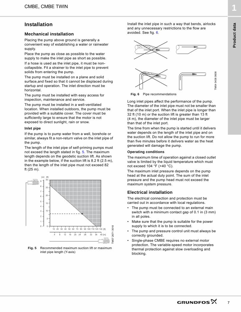
The length of the inlet pipe of self-priming pumps must not exceed the length stated in fig. 5. The maximum length depends on the geodetic suction lift. As shown in the example below, if the suction lift is 8.2 ft (2.5 m), then the length of the inlet pipe must not exceed 82 ft (25 m).
Fig. 5 Recommended maximum suction lift or maximum inlet pipe length (Y-axis)
Install the inlet pipe in such a way that bends, airlocks and any unnecessary restrictions to the flow are avoided. See fig. 6.
Fig. 6 Pipe recommendations
Long inlet pipes affect the performance of the pump. The diameter of the inlet pipe must not be smaller than that of the inlet port. When the inlet pipe is longer than 32 ft (10 m) or the suction lift is greater than 13 ft (4 m), the diameter of the inlet pipe must be larger than that of the inlet port.
The time from when the pump is started until it delivers water depends on the length of the inlet pipe and on the suction lift. Do not allow the pump to run for more than five minutes before it delivers water as the heat generated will damage the pump.
Operating conditions
The maximum time of operation against a closed outlet valve is limited by the liquid temperature which must not exceed 104 °F (+40 °C).
The maximum inlet pressure depends on the pump head at the actual duty point. The sum of the inlet pressure and the pump head must not exceed the maximum system pressure.
Electrical installationThe electrical connection and protection must be carried out in accordance with local regulations.
• The pump must be connected to an external main switch with a minimum contact gap of 0.1 in (3 mm) in all poles.
• Make sure that the pump is suitable for the power supply to which it is to be connected.
• The pump and pressure control unit must always be correctly grounded.
• Single-phase CMBE requires no external motor protection. The variable-speed motor incorporates thermal protection against slow overloading and blocking.
TM
07
26
71
30
180 0
5
10
15
20
25
1
2
3
4
5
6
7
8
9
[m] [ft]
4 8 12 16 20 24 28 32 36 40 [m]
[ft]10 20 30 40 50 60 70 80 90 100 110 120 130
30
TM
04
04
38
06
08
7

Pro
du
ct d
ata
CMBE, CMBE TWIN1
8
Selection guides for residential applicationsThe following instructions primarily target residential applications. This is a quick and easy guide to show you which product is ideal for your needs. Follow the charts and instructions, and you will be sure to get a perfect fit. Example:
Fig. 7 Sizing and selection example
1 x 230 V supply power flow rate selection chart
* Indicates pump may be 5-10 % undersized on flow at desired pressure.
1 x 115 V supply power flow rate selection chart
* Indicates pump may be 5-10 % undersized on flow at desired pressure.
TM
07
27
42
30
18
A: Required comfort level• Adjustable constant pressure.B: Find the right booster• How many taps? 6.• How many floors? 3.Result: CMBE 1-75
Number of taps
1-5 6-10 11-20 21-50
Nu
mb
er
of
flo
ors
4 CMBE 1-75 CMBE 1-75 CMBE 3-62 CMBE 3-93
3 CMBE 1-44 CMBE 1-75 CMBE 3-62 CMBE 3-62
2 CMBE 1-44 CMBE 1-44 CMBE 3-62 CMBE 3-62
1 CMBE 1-44 CMBE 1-44 CMBE 3-30 CMBE 3-62Tapping point
Height40 ft
(12 m)
PSI boost 0-15 gpm 0-25 gpm 0-35 gpm 0-45 gpm 0-55 gpm 0-65 gpm 0-70 gpm
20 CMBE 1-44 CMBE 3-30 CMBE 5-31 CMBE 10-54 CMBE 10-54 CMBE 10-54 CMBE 10-54
25 CMBE 1-44 CMBE 3-30* CMBE 5-31 CMBE 10-54 CMBE 10-54 CMBE 10-54 CMBE 10-54
30 CMBE 1-75 CMBE 5-31 CMBE 5-31 CMBE 10-54 CMBE 10-54 CMBE 10-54 CMBE 10-54*
35 CMBE 1-75 CMBE 3-62 CMBE 5-31 CMBE 10-54 CMBE 10-54 CMBE 10-54* -
40 CMBE 1-75 CMBE 3-62 CMBE 5-62 CMBE 10-54 CMBE 10-54* - -
45 CMBE 1-75 CMBE 3-62 CMBE 5-62 CMBE 10-54* - - -
50 CMBE 1-99 CMBE 3-62 CMBE 5-62 CMBE 10-54* - - -
55 CMBE 1-99 CMBE 3-93 CMBE 5-62 - - - -
60 CMBE 1-99 CMBE 3-93 CMBE 5-62 - - - -
65 CMBE 1-99 CMBE 5-62 - - - - -
70 CMBE 3-93 CMBE 5-62 - - - - -
75 CMBE 3-93 CMBE 5-62 - - - - -
80 CMBE 3-93 CMBE 5-62 - - - - -
PSI boost 0-10 gpm 0-15 gpm 0-20 gpm 0-25 gpm
20 CMBE 1-44 CMBE 1-44 CMBE 3-30 CMBE 3-30
25 CMBE 1-44 CMBE 1-44 CMBE 3-30 CMBE 3-30
30 CMBE 1-44 CMBE 1-44 CMBE 3-30 CMBE 3-51
35 CMBE 1-44 CMBE 1-75 CMBE 3-51 CMBE 3-51*
40 CMBE 1-44 CMBE 3-51 CMBE 3-51* CMBE 3-51*
45 CMBE 1-44 CMBE 3-51 CMBE 3-51* -
50 CMBE 1-44 CMBE 3-51 - -
55 CMBE 1-75 CMBE 3-51* - -
60 CMBE 1-75 CMBE 3-51* - -
65 CMBE 1-75* - - -
70 CMBE 1-75* - - -
75 CMBE 1-75* - - -
80 CMBE 1-75* - - -

CM
BE
TW
IN
CMBE, CMBE TWIN 2
2. CMBE TWIN
Fig. 8 CMBE TWIN
ApplicationsThe compact Grundfos CMBE TWIN is suitable for clean water supply and pressure boosting in domestic and commercial applications. The CMBE TWIN keeps a constant pressure in the pipe system and is mainly used in places such as:
• two-family houses
• cluster homes
• apartment buildings
• schools
• small hotels
• small office buildings
• small industrial plants and businesses
• hospitals
• agriculture and irrigation.
Product descriptionThe CMBE TWIN system consists of two CMBE pumps connected in parallel and mounted on a common base plate. Each CMBE pump includes a Grundfos integrated variable frequency drive (VFD). Each CMBE pump is delivered complete with 5-way fittings, non-return valves, diaphragm tank, pressure sensor and pressure gauge.
Fig. 9 CMBE TWIN components
MotorNo external motor protection is required. The MLE motor incorporates thermal protection against slow overloading and blocking.
Features • Constant pressure via integrated speed control
• cascade control and pump alternation
• dry-running protection
• compact
• robust, stainless steel design
• easy installation
• low energy consumption
• noise level below 58 dBA and even lower at controlled speed.
Constant pressure
The integrated speed controller keeps a constant pressure in the pipe system. A pressure sensor monitors changes in the water consumption and signals to the speed controller to adjust the motor speed up or down.
TM
07
28
93
43
18
TM
07
19
42
30
18
Pos. Description
1 Diaphragm tank
2 Pressure sensor
3 5-way fitting with integrated non-return valve
4 CME pump
5 Base plate
6 Pressure gauge
7 Inlet/outlet pipes with ball valves and unions
1
23
4
5
6
7
9
CM
BE
TW
IN
CMBE, CMBE TWIN2
10
Cascade control
Cascade control ensures that the performance of the booster system is automatically adapted to the consumption by switching pumps on or off and by changing the speed of the pumps in operation. The system runs as energy-efficiently as possible with a constant pressure and only with the number of pumps required.
Pump alternation
Pump alternation ensures that the operating hours are distributed evenly on the pumps over time. CMBE TWIN automatically alternates the pumps and will start the available pump with the lowest number of running hours since the last time the power was switched off.
Dry-running protection
Dry-running protection is very important as dry running may damage the bearings and shaft seals. Lack of inlet pressure or water shortage is indicated by the motor speed. When dry running is detected, the CMBE will stop and go into alarm mode.
Easy installation
CMBE TWIN is easy to install. When the CBME TWIN has been connected to the pipes and to the power supply, the system is operational.
Operating conditions
Electrical data
* CMBE TWIN is for fuse box connection and has 15 ft (4.5 m) cable (no plug).
ApprovalsDrinking water certifications:
UL Electrical:
1 x 230 V CMBE models: UL Listed Packaged Pumping System
Wetted parts
The table below specifies the parts of the pump that are in contact with the pumped liquid.
System pressure Max. 145 psi (10 bar) (1 MPa).
Suction liftMax. 3.28 ft (1 m), including suction-pipe pressure loss at a liquid temperature of 68 °F (+20 °C).
Liquid temperature 32-140 °F (0-60 °C).
Ambient temperatureMax. 131 °F (+55 °C).
Min. -4 °F/ (-20 °C).
Relative humidity Max. 95 %.
Enclosure class IP55.
Insulation class F.
Sound pressure level ≤ 58 dB(A)
Supply voltage1 x 115 V, 60 Hz,1 x 200-240 V, 60 Hz.
Start/stop frequency Max. 100 per hour.
Cut-in pressure 7.25 psi (0.5 bar) below setpoint.
CMBE TWIN 1-44 3-51 10-54PlugtypeSupply voltage
1 x 115 V60 Hz
1 x 115 V60 Hz
1 x 200-240 V60 Hz
Max. current for both pumps combined - high value [A]
16 16 18.2
See below*
Max. current for both pumps combined - low value [A]
16 16 18.2
Max. power for both pumps combined power (P1) [W]
1265.2 1749 3404
TM
06
36
26
02
15
TM
06
36
27
02
15
Designation Material Technical description
Pump sleeve Stainless steel AISI 304 / EN 1.4301
Impeller Stainless steel AISI 304 / EN 1.4301
Diffuser Technopolymer PP 20 % Talc
Ejector Technopolymer PPE/PS 20 % GF
Nozzle Stainless steel AISI 304 / EN 1.4301
Shaft Stainless steel AISI 304 / EN 1.4301
Shaft seal Carbon with resin/ceramic CVBP
Filling plug Technopolymer PES 30 % GF
Drain plug Technopolymer PES 30 % GF

CM
BE
TW
IN
CMBE, CMBE TWIN 2
Dimensional drawings, CMBE TWIN
TM
07
28
34
42
18
Pump typeH3
[in (mm)]H2
[in (mm)]H1
[in (mm)]L1
[in (mm)]L2
[in (mm)]L3
[in (mm)]L4
[in (mm)]A
[in (mm)]A1[in]
A2[in]
Net wt[lb (kg)]
CMBE TWIN1-44
19.6 (498) 9.25 (235) 4.25 (108) 19.6 (498) 9.85 (250) 18.51 (470) 20.35 (517) 12.3 (313) 1 1/2 NPT 1 1/2 NPT 120 (54.5)
CMBE TWIN3-51
19.6 (498) 9.25 (235) 4.25 (108) 19.6 (498) 9.85 (250) 18.51 (470) 20.35 (517) 12.3 (313) 1 1/2 NPT 1 1/2 NPT 123 (55.8)
CMBE TWIN10-54
22.0 (559) 11.0 (280) 4.61 (117.1) 21.1 (536) 11.82 (300) 20.48 (520) 26.81 (681) 16.3 (414) 2 NPT 2 NPT 180 (81.7)
A1
A2
H2
H1
L1
L3
L2 A
9.8 in(249 mm)
L4
H3
11

CM
BE
TW
IN
CMBE, CMBE TWIN2
12
Control panelThe control panel on the pump terminal box makes it possible to change the setpoint settings manually.
The operating condition of the pump is indicated by the
Grundfos Eye on the control panel.
Fig. 10 Control panel
TM
05
48
48
35
12
Pos. Symbol Description
1Grundfos EyeShows the operating status of the pump.
2 - Light fields for indication of setpoint.
3 Changes the setpoint.
4Enables radio communication with the Grundfos GO Remote and other products of the same type.
5
Makes the pump ready for operation/starts and stops the pump. Start: If the button is pressed when the pump is stopped, the pump will only start if no other functions with higher priority have been enabled.Stop: If the button is pressed when the pump is running, the pump will always be stopped. When the pump is stopped via this button, the "Stop" text next to the button will illuminate.
1
2
3
4
5Stop

CM
BE
TW
IN
CMBE, CMBE TWIN 2
Performance curves
TM
07
38
69
05
19
0 5 10 15 20 25 30 35 40 45 50 55 60 Q [US GPM]
0
20
40
60
80
100
120
140
160
180
200
[ft]H
0
10
20
30
40
50
60
[m]H
CMBE TWIN50/60 Hz
ISO 9906:2012 3B
1-44 3-51 10-54
0 10 20 30 40 50 60 70 80 90 100 110 120 Q [US GPM]
0
1 Pump
2 Pumps
13

CM
BE
CMBE, CMBE TWIN3
14
3. CMBE
CMBE
Fig. 11 CMBE
ApplicationsThe compact Grundfos CMBE is suitable for clean water supply and pressure boosting in domestic and light commercial applications.
The CMBE keeps a constant pressure in the pipe system and is mainly used in places such as:
● Recommended❍ Applicable.
Product descriptionThe CMBE consists of these components:
• CMBE pump with integrated frequency drive
• 5-way fitting with non-return valve
• diaphragm tank
• pressure gauge
• pressure sensor
• inlet pressure switch (optional).
Fig. 12 CMBE components
TM
07
28
92
43
18
Application CMBE 1 CMBE 3 CMBE 5 CMBE 10
Single-family houses ● ● ❍ ❍Two-family houses ❍ ● ● ●
Cluster homes ● ● ●
Apartments ● ● ●
Schools ● ● ●
Small hotels/guest houses ● ● ●
Small office buildings ● ● ●
Agriculture ❍ ● ●
Irrigation ❍ ● ●
TM
06
07
94
02
14
Pos. Description
1 Diaphragm tank
2 Pressure gauge
3 Five-way fitting with integrated non-return valve
4 CMBE pump
5 Pressure sensor

CM
BE
CMBE, CMBE TWIN 3
MotorNo external motor protection is required. The MLE motor incorporates thermal protection against slow overloading and blocking.
Features
• Constant pressure via integrated speed control
• dry-running protection
• compact
• robust, stainless steel design
• easy installation
• low energy consumption
• noise level below 55 dBA and even lower at controlled speed.
Constant pressure
The integrated speed controller keeps a constant pressure in the pipe system. A pressure sensor monitors changes in the water consumption and signals to the speed controller to adjust the motor speed up or down.
Dry-running protection
Dry-running protection is very important as dry running may damage the bearings and shaft seals. The inlet pressure of the system or the water level in a possible tank on the inlet side is monitored. Lack of inlet pressure or water shortage is indicated by the motor speed. When dry running is detected, the CMBE will stop and go into alarm mode.
Easy installation
The CMBE is easy to install. When the CMBE has been connected to the pipes and to the power supply, the system is operational.
Operating conditions
Electrical data
ApprovalsDrinking water certifications:
1 x 230 V CMBE models: UL Listed Packaged Pumping System
Wetted partsThe table below specifies the parts of the pump that are in contact with the pumped liquid.
System pressure Max. 145 psi (10 bar)(1 MPa).
Suction liftMax. 3.28 ft (1 m), including suction-pipe pressure loss at a liquid temperature of 68 °F (+20 °C).
Liquid temperature 32-140 °F (0-60 °C).
Ambient temperatureMax. 131 °F (+55 °C).
Min. -4 °F (-20 °C).
Relative humidity Max. 95 %.
Enclosure class IP55.
Insulation class F.
Sound pressure levelThe sound pressure level of the pump is below 55 dB(A).
Supply voltage1 x 115 V, 60 Hz,1 x 200-240 V, 60 Hz.
Start/stop frequency Max. 100 per hour.
Cut-in pressure 7.25 psi (0.5 bar) below setpoint.
Pump typeVoltage
[V]Imax [A]
P1[W]
CMBE 1 x 200-240 V
CMBE 1-44 1 x 200-240 3.4 - 2.9 685
CMBE 1-75 1 x 200-240 6.55 - 5.45 969
CMBE 1-99 1 x 200-240 6.55 - 5.45 1050
CMBE 3-30 1 x 200-240 6.55 - 5.45 815
CMBE 3-62 1 x 200-240 6.55 - 5.45 1220
CMBE 3-93 1 x 200-240 8.9 - 7.45 1300
CMBE 5-31 1 x 200-240 6.55 - 5.45 1300
CMBE 5-62 1 x 200-240 8.9 - 7.45 1400
CMBE 10-27 1 x 200-240 6.55 - 5.45 1190
CMBE 10-54 1 x 200-240 9.1 - 7.6 1250
CMBE 1 x 115 V
CMBE 1-44 1 x 115 8 1100
CMBE 1-75 1 x 115 8 1100
CMBE 3-30 1 x 115 8 1100
CMBE 3-51 1 x 115 8 1100
TM
06
36
26
02
15
TM
06
36
27
02
15
Designation Material Technical description
Pump sleeve Stainless steel AISI 304 / EN 1.4301
Impeller Stainless steel AISI 304 / EN 1.4301
Diffuser Technopolymer PP 20 % Talc
Ejector Technopolymer PPE/PS 20 % GF
Nozzle Stainless steel AISI 304 / EN 1.4301
Shaft Stainless steel AISI 304 / EN 1.4301
Shaft seal Carbon with resin/ceramic CVBP
Filling plug Technopolymer PES 30 % GF
Drain plug Technopolymer PES 30 % GF
15

CM
BE
CMBE, CMBE TWIN3
16
Dimensional drawings, CMBE
TM
06
08
02
_0
91
4
Pump typeH1
[in (mm)]H2
[in (mm)]H3
[in (mm)]L1
[in (mm)]B2 (L2)
[in (mm)]A1[in]
A2[in]
CMBE 1-442.95 (75) 7.87 (200) 17.32 (440) 12.83 (326) 8.54 (217) 1 NPT 1 NPT
2.95 (75) 7.87 (200) 17.32 (440) 12.83 (326) 8.54 (217) 1 NPT 1 NPT
CMBE 1-752.95 (75) 7.87 (200) 17.32 (440) 12.83 (326) 8.54 (217) 1 NPT 1 NPT
2.95 (75) 7.87 (200) 17.32 (440) 14.25 (362) 8.54 (217) 1 NPT 1 NPT
CMBE 1-99 2.95 (75) 7.87 (200) 17.32 (440) 15.66 (398) 8.54 (217) 1 NPT 1 NPT
CMBE 3-302.95 (75) 7.87 (200) 17.32 (440) 12.83 (326) 8.54 (217) 1 NPT 1 NPT
2.95 (75) 7.87 (200) 17.32 (440) 12.83 (326) 8.54 (217) 1 NPT 1 NPT
CMBE 3-51 2.95 (75) 7.87 (200) 17.32 (440) 12.83 (326) 8.54 (217) 1 NPT 1 NPT
CMBE 3-62 2.95 (75) 7.87 (200) 17.32 (440) 13.54 (344) 8.54 (217) 1 NPT 1 NPT
CMBE 3-93 3.54 (90) 8.46 (215) 17.91 (455) 15.90 (404) 8.54 (217) 1 NPT 1 NPT
CMBE 5-31 2.95 (75) 7.87 (200) 17.32 (440) 12.83 (326) 8.54 (217) 1 NPT 1 1/4 NPT
CMBE 5-62 3.54 (90) 8.46 (215) 17.91 (455) 13.77 (350) 8.54 (217) 1 NPT 1 1/4 NPT
CMBE 10-54 3.62 (92) 9.96 (253) 20.07 (510) 14.84 (377) 9.13 (232) 1 1/2 NPT 1 1/2 NPT

CM
BE
CMBE, CMBE TWIN 3
Materials Control panelThe control panel on the E-pump terminal box makes it possible to change the setpoint settings manually.
The operating condition of the pump is indicated by the Grundfos Eye on the control panel.
Fig. 13 Control panel
Designation Material
Terminal box Composite PC/ASA and silumin (Alu)
Stator housing Silumin (Alu)
Fan cover Composite PBT/PC
Pump housing Stainless steel, AISI 304 / EN 1.4301
Shaft and impeller Stainless steel, AISI 304 / EN 1.4301
Flange Cast iron
TM
05
48
48
35
12
Pos. Symbol Description
1Grundfos EyeShows the operating status of the pump.
2 - Light fields for indication of setpoint.
3 Changes the setpoint.
4Enables radio communication with the Grundfos GO Remote and other products of the same type.
5
Makes the pump ready for operation/starts and stops the pump. Start: If the button is pressed when the pump is stopped, the pump will only start if no other functions with higher priority have been enabled.Stop: If the button is pressed when the pump is running, the pump will always be stopped. When the pump is stopped via this button, the "Stop" text next to the button will illuminate.
1
2
3
4
5Stop
17

CM
BE
CMBE, CMBE TWIN3
18
Performance curves
TM
06
14
20
06
14
0 5 10 15 20 25 30 35 40 45 50 55 60 Q [US GPM]
0
20
40
60
80
100
120
140
160
180
200
220
240
260
280
300
320
340
360
380
[ft]H
0 2 4 6 8 10 12 14 Q [m³/h]
0
10
20
30
40
50
60
70
80
90
100
110
[m]H
CMBE50/60 Hz
ISO 9906:2012 3B
3-30
3-51
3-62
3-93
1-44
1-75
1-99
10-545-31
5-62

Pro
du
ct
nu
mb
ers
CMBE, CMBE TWIN 4
4. Product numbers
CMBE TWINWith integrated variable frequency drive.
CMBE TWIN 1 x 220-240 V, 60 Hz
CMBE TWIN 1 x 115 V, 60 Hz
CMBEWith integrated variable frequency drive.
CMBE 1 x 200-240 V, 60 Hz
CMBE 1 x 115 V, 60 Hz
Pump type Product number
CMBE 10, 1 x 200-240 V, 60 Hz
CMBE TWIN 10-54 99503875
Pump type Product number
CMBE 1, 1 x 115 V, 60 Hz
CMBE TWIN 1-44 99503861
CMBE 3, 1 x 115 V, 60 Hz
CMBE TWIN 3-51 99503873
Pump type Product number
CMBE 1, 1 x 200-240 V, 60 Hz
CMBE 1-44 98548109
CMBE 1-75 98548110
CMBE 1-99 98548111
CMBE 3, 1 x 200-240 V, 60 Hz
CMBE 3-30 98548112
CMBE 3-62 98548113
CMBE 3-93 98548114
CMBE 5, 1 x 200-240 V, 60 Hz
CMBE 5-31 98548115
CMBE 5-62 98548116
CMBE 10, 1 x 200-240 V, 60 Hz
CMBE 10-54 98548118
Pump type Product number
CMBE 1, 1 x 115 V, 60 Hz
CMBE 1-44 98810910
CMBE 1-75 98810921
CMBE 3, 1 x 115 V, 60 Hz
CMBE 3-30 98810922
CMBE 3-51 98810924
19

Gru
nd
fos
Pro
du
ct C
en
ter
CMBE, CMBE TWIN5
20
5. Grundfos Product Center
"REPLACEMENT" enables you to find a replacement product. Search results willinclude information on the following:
• the lowest purchase price• the lowest energy consumption• the lowest total life cycle cost.
"CATALOG" gives youaccess to the Grundfos product catalog.
"LIQUIDS" enables you to find pumps designed for aggressive, flammable or other special liquids.
All the information you need in one place Downloads
Performance curves, technical specifications, pictures, dimensional drawings, motor curves, wiring diagrams, spare parts, service kits, 3D drawings, documents, system parts. The Product Center displays any recent and saved items - including complete projects - right on the main page.
On the product pages, you can download installation and operating instructions, data booklets, service instructions, etc. in PDF format.
Online search and sizing tool to help you make the right choice.
http://product-selection.grundfos.com
"SIZING" enables you to size a pump based on entered data and selection choices.
Select between "Products" and "Literature" when searching for the document.

21

98647967 0219
ECM: 1255918
Grundfos Kansas City9300 Loiret BoulevardLenexa, Kansas 66219Phone: 913-227-3400Fax: 913-227-3500www.grundfos.us
Grundfos Canada2941 Brighton RoadOakville, Ontario L6H 6C9 CanadaPhone: +1-905-829-9533Fax: +1-905-829-9512www.grundfos.ca
Grundfos MéxicoBoulevard TLC No. 15Parque Industrial Stiva AeropuertoC.P. 66600 Apodaca, N.L. MexicoPhone: 011-52-81-8144 4000Fax: 011-52-81-8144 4010www.grundfos.mx T
rad
em
ark
s d
isp
laye
d in
th
is m
ate
ria
l, in
clu
din
g b
ut
no
t lim
ited
to
Gru
nd
fos,
th
e G
run
dfo
s lo
go
an
d “
be
th
ink
inn
ova
te”
are
re
gis
tere
d t
rad
em
ark
s o
wn
ed
by
Th
e G
run
dfo
s G
rou
p.
All
rig
hts
re
serv
ed
.©
20
19
Gru
nd
fos
Ho
ldin
g A
/S,
all
rig
hts
re
serv
ed
.