Horizontal Machining Center · * The ball screws are core-cooled ball screws and double anchored. *...
22
OKK CANADA OFFICE(CANADA) 79 REGAL ROAD, UNITS 17 & 18, GUELPH, ONTARIO NIK 1B6 CANADA TEL:(1)630-924-9000 FAX:(1)630-924-9010 14.07.4M( T ) OKK(SHANGHAI) CO., LTD. ROOM 2506, 2201 YAN AN ROAD(W.) CHANGNING DISTRICT SHANGHAI. 200336 CHINA TEL:(86)21-62700930 FAX:(86)21-62700931 http://www.okk.com.cn E-mail:[email protected] Horizontal Machining Center
Transcript of Horizontal Machining Center · * The ball screws are core-cooled ball screws and double anchored. *...

OKK CANADA OFFICE(CANADA)79 REGAL ROAD, UNITS 17 & 18, GUELPH, ONTARIO NIK 1B6 CANADATEL:(1)630-924-9000FAX:(1)630-924-9010
14.07.4M(T)
OKK(SHANGHAI) CO., LTD.ROOM 2506, 2201 YAN AN ROAD(W.) CHANGNING DISTRICTSHANGHAI. 200336 CHINATEL:(86)21-62700930FAX:(86)21-62700931http://www.okk.com.cnE-mail:[email protected]
Horizontal Machining Center

0201
HM400/40, HM400/50
Travel X x Y x Z mm (in) =630 (24.80)x620 (24.41)x710 (27.95)Rapid traverse rate m/min (ipm)=54 (2,126)Pallet size square mm (in) =400 (15.75)HM500S/40, HM500S/50
Travel X x Y x Z mm (in) =630 (24.80)x620 (24.41)x710 (27.95)Rapid traverse rate m/min (ipm)=54 (2,126)Pallet size square mm (in) =500 (19.69)*/40:BT40 type, /50:BT40 type
HM1000Travel X x Y x Z mm (in) =1700(66.93)x1400(55.12)x1400(55.12)Rapid traverse rate m/min (ipm) = 48(1889)Pallet size square mm (in) =1000(39.37)HM1250STravel X x Y x Z mm (in) =1700(66.93)x1400(55.12)x1240(48.82)Rapid traverse rate m/min (ipm) = 48(1889)Pallet size square mm (in) =1250(49.21)
HM800Travel X x Y x Z mm (in) =1400(55.12)x1100(43.31)x1050(41.34)Rapid traverse rate m/min (ipm) = 48(1889)Pallet size square mm (in) =800(31.5)HM1000STravel X x Y x Z mm (in) =1400(55.12)x1100(43.31)x1000(39.37)Rapid traverse rate m/min (ipm) = 48(1889)Pallet size square mm (in) =1000(39.37)
HM630Travel X x Y x Z mm (in)=1050 (41.34) x 900 (35.43) x 900 (35.43)Rapid traverse rate m/min (ipm) = [Std] 54 (2126)
= [Opt] 75 (2953)Pallet size square mm (in) = 630 (24.8)HM800STravel X x Y x Z mm (in)=1050 (41.34) x 900 (35.43) x 880 (34.65)Rapid traverse rate m/min (ipm) = [Std] 54 (2126)
= [Opt] 75 (2953)Pallet size square mm (in)= 800 (31.5)
HM-series horizontal machining centers are built with OKK’s exceptional designs and provided with superior performance ensuring high-speed machining, rigidity, reliability, and chip evacuation. Heavy cutting capability is just one of HM-series specialties achieved by incorporating a highly developed rigid box-shaped frame.Add to that the implementation of only the best in high-speed motors, and extremely reliable ATC’s (auto tool changer) and APC’s (auto pallet changer) that deliver minimal chip to chip time, truly merging max performance with production proven reliability.
Main specifications
Main specifications
Main specifications
Main specifications
ATC(Automatic tool changer) ......15Powerful feeding ...............16Accuracy ..........................17Cutting capacity ...............18Operations........................19Maintenance.....................20Standard and option list....21
Option P 22Software...........................29
Controller P 31F31i-B...............................31FAi .................................. 32
Specifications P33HM400/HM500S ................33HM5000/HM6300S ............35HM630/HM800S ................37HM800/HM1000S ..............39HM1000/HM1250S............41
Main features P01
Features P03Chip disposal ....................06High speed and heavy-duty cutting ....07Spindle power andtorque diagram ................09Pallet table and APC .........11High precision structure....12Tool magazine ...................13
C O N T E N T S
[Std] Standard equipment or function[Opt] Optional equipment or function
Horizontal Machining Centers
HM5000Travel X x Y x Z mm (in) =800 (31.50) x 750 (29.53) x 880 (34.65)Rapid traverse rate m/min (ipm) = [Std] 60 (2362)
= [Opt] XZ: 75 (2953), Y: 60 (2362)Pallet size square mm (in) =500 (19.69)HM6300STravel X x Y x Z mm (in) =800 (31.50) x 750 (29.53) x 880 (34.65)Rapid traverse rate m/min (ipm) = [Std] 60 (2362)
= [Opt] XZ: 75 (2953), Y: 60 (2362)Pallet size square mm (in) =630 (24.8)
Main specifications

HM5000/HM6300S
* The machining time is significantly improved by increasing all of speeds.* The ball screws are core-cooled ball screws and double anchored.* Option of a BT40 is with 10000 min-1 or BT50 with 12000 min-1 is available to meet your machining needs.* One piece shutters are used for X and Z axes and avoids chips and coolant going to inside.
In addition to the high rigidity of the machine main unit, highly-rigid linear roller guides on the X, Y and Z axes generate a synergetic effect and improve further the cutting performance.
Increase in the rapid-traverse rates, ATC speed, table turning speed and APC speed has shortened the non-cutting time and improved production efficiency.
For the improved heavy-duty cutting performance, the machine has a BT50 large-diameter ø100mm (3.94”) spindle and a 45/30/26kW (60/40/35HP) high-power motor.
features
0403
*1: HM800/HM1000S and HM1000/HM1250S use worm shaft and worm wheel. *2: HM400/HM500S is using center-clamping method. *3: Master pallet is available only for HM5000/HM6300S.*4: Additional option available rapid traverse rate to 75m/min(2953ipm) for X-axis and Z-axis. *5: An air tank is necessary to attach a balance cylinder to Y axis. The air tank needs local procurement at machine export.
Not only the rigidity but also spindle speed, rapid traverse, reliability and machining performance have been upgraded.
HM400/40 and HM500S/40 models come equipped with a 10000min-1 spindle, with an output of 37/26/22kW (50/35/30HP) available in BT40 spindle taper, as well as the option for a 15000min-1 or 20000min-1 spindle. HM400/50 and HM500S/50 models have a standard spindle reaching 12000 min-1, with an output of 30/25kW (40/34HP) available in BT50 spindle taper, with an optional 8000min-1. Allows customers the best option for the job.
The unique clamp construction provides excellent sealing performance by clamping while increasing the internal pressure of the table, thus preventing the infiltration of coolant enhancing the durability of the machines.
HM Series
With more rigid construction than conventional models, responding to the needs to machining a wide range of products from iron and cast iron to mold and die parts.
Double the speed, rigidity, reliability, durability, etc. compared with the conventional machines enable high-speed and high-accuracy machining of wide-ranging materials including hard-to-cut materials such as ferrous and casting materials.
(only Z-axis shutter is one piece type for HM400/50 and HM500S/50.)
High rigid linear roller guides are used for all axes of X, Y and Z.
The ball screws are core-cooled ball screws and pre tensioned by double-anchor method. Cooling oil is forced to all ball screws, ball screw support housings and motor mounting surfaces.
The fine-feed movement and the lost motion property have been improved. The circular cutting accuracy is also improved significantly.
Built - in - Rotary Table (BRT) use a new mechanism of precision reduction-gear roller drive. This drive system achieved high speed table indexing and toughness against overload or impact. *1
Pallet positioning and clampingUse of taper cones ensures high accurate repeatability of pallet positioning and flatness of the pallet is secured by means of OKK’s original design multiple-clamp method.*2 Master pallet is available as option.*3
* Linear roller guides are capable the six times more moment load than a conventional model.* BRT use the high speed and high rigid reduction-gear roller drive that is more than double the rigidity and clamping torque
compared to a conventional model. *1
Specifications Type of tool shank Spindle bearing inner diameter (mm) Rapid traverse rate (m/min)HM5000/HM6300SHM630/HM800S
HM800/HM1000SBT50 ø100 (3.94”)
Spindle speed (min-1)
12000
8000
60 (2362 ipm) [Opt. 75 (2953 ipm)]*4
54 (2126 ipm) [Opt. 75 (2953 ipm)]*5
48 (1889 ipm)
CharacteristicsCharacteristicsCharacteristicsCharacteristicsCharacteristicsCharacteristics

Chips are discharged from the troughs to outside of machine by big volume of coolant.
Adopting twin-ball-screw drives and synchro-nously control for the Y and Z axes, suppresses vibrations and improves machining quality.
Furthermore for severe heavy-duty cutting, a larger spindle bearing diameter of 120 mm (4.72”) with maximum spindle speed of 8000 min-1, high-power spindle motor of 37/30 kW (50/40HP) and high-torque motorized spindle of 1009 N・m (744 ft・lbs) is available as option on HM1000/HM1250S.
All HM models are highly effective in machining cast-metal and iron-based work pieces, including construction machinery parts, such as cylinder blocks with massive valves requir-ing maximum rigidity for custom tooling and large molds.
The Z-axis shutters and B-axis are angled sharply, allowing for excellent chip evacuation. Furthermore, OKK added a solid Y-axis shutter to eliminate any problems previously caused from chips clogging on un-maintained slide rails.
features HM Series
chip disposalHM Series
0605
Z axis twin-ball-screw
* HM1000 and HM1250S models standard spindle delivers 12000min-1, with a bearing diameter of 100mm (3.94”) and 30/25kW (40/34HP), 420N·m (310 ft・lbs) of torque.
*Twin-ball-screws for both Y-and Z-axes, aiding in vibration dampening yielding extended tool life. The design focus is reduction of machining time, while increasing precision, surface finish, and contouring accuracy.HM-series are proven in high production machining environments and are ready to cut aluminum to cast metals.
CharacteristicsCharacteristicsCharacteristics
HM400/M500S HM5000/HM6300S
Coil conveyor *2
Coil conveyor *2
Z-axis shutter
Table body
*1: Standard for HM400/500S, HM5000/HM6300S, HM800/HM1000S.*2: Standard for HM630/HM800S, HM1000/HM1250S.
Lift-up chip conveyor andchip-bucket are option.
Chip flow coolant *1
Ceiling shower [Opt]
Thorough chip processing measures
26 nozzles for HM400/HM500S29 nozzles for HM5000/HM6300S30 nozzles for HM630/HM800S
50 nozzles for HM800/HM1000S91 nozzles for HM1000/HM1250S
Coolant through nozzles on the ceiling i.e. ceiling shower can be provided optionally for prevention of chips from accumulating on fixtures and workpieces.
The troughs are extended and chips at the setup station can be collected.
Chips are flushed so that they fall into the troughs on both sides of the table. Then, the chips are flushed out with coolant supplied though the nozzles provided in the front-end section of each trough. The coolant and chips are collected in the chip tank in the rear part of the machine (Chip flow coolant *1). In place of the standard method that flushes out chips with coolant, you may use optional coil-type chip conveyor *2 to clear the troughs and to discharge chips through the outlet in the rear part of the machine.
HM630/HM800S HM1000/HM1250SHM400/HM500S

MS: Motorized spindle
0807
High Speed and Heavy-duty Cutting
Power of tool clamp
Gear-drive spindle [Opt]
The standard spindle used for HM800/HM1000S is the BT50 spindle having the output of 30/25 kW (40/34 HP) and rotating at 8000 min-1. The maximum torque of 420 N・m (310 ft・lbs) can provide high power in the low-speed range.Both the heavy-duty cutting and the high-speed machining are available owing to the highly-rigid spindle with ø100mm (3.94”) spindle bearing inner diameter and the oil-air lubrication system.
As an option to deliver more torque for machining of hard-to-cut materials, an 8000min-1 high torque gear-drive spindle produces 1251 N・m (923 ft・lbs). Available on HM630/HM800S and HM800/HM1000S.
HM630 / HM800S and HM800 / HM1000SGear-drive spindle [Opt]
Machine modelMaterial
ToolLength of the tool from tool holder nose
Spindle speedFeed rate
Depth of cutWidth of cut
HM1000SMold steel (SKD61)
ø80mm (3.15”) End milling200mm (7.87”)
1600mm-1
1920mm/min (75.6in/min)4.0mm (0.16”)
60.0mm (2.36”)
Cutting data
High speed and Heavy-duty cuttingHM Series
Machine modelHM630/HM800S
HM800/HM1000S
Spindle speed 8000min-1
19600N (4400lbf) [Opt]19600N (4400lbf) [Opt]
Gear spindle
MS spindleMachine model
HM400/50, HM500S/50
HM5000/HM6300SHM630/HM800S
HM800/HM1000SHM1000/HM1250S
Spindle speed 8000min-1
16300N (3700lbf) [Opt] –16300N (3700lbf) [Opt]17700N (4000lbf)20600N (4600lbf) [Opt]
Spindle speed 12000min-1
16300N (3700lbf)16300N (3700lbf)16300N (3700lbf)16300N (3700lbf) [Opt]16300N (3700lbf)
MS spindleMachine model
HM400/40, HM500S/40
Spindle speed 20000min-1
10000N (2200lbf) [Opt]Spindle speed 15000min-1
10000N (2200lbf) [Opt]Spindle speed 10000min-1
10000N (2200lbf)
Standard Spindle 10,000min-1
Machine model HM400/40
Cutting data
Material S50C Tool ø32 mm (1.26") Long end milling Length of the tool from tool holder nose 130 mm (5.12”) Spindle speed 1300 min-1
Feed rate 6500 mm/min (256 ipm) Depth of cut 0.5 mm (0.02") Width of cut 20 mm (0.79")
Radiation coolingsystem
Cooling oil
Rotor Stator
Grease lubrication for bearings
The BT50 spindle rotating at 12000 min-1 secures the 45/30/26kW (60/40/35HP) output. For the bearing lubrication, the machine uses the oil-air lubrication. The spindle specification can be selected according to the details of machining.
The spindle bearings are oil-air lubricated. Circulating temperature controlled oil is in the groove around the spindle housing suppressing the growth of the spindle. Furthermore, OKK’s unique radiant cooling system prevents the conduction of heat generated from the motor into the spindle.
Circulating the temperature-controlled oil around the spindle housing minimize the spindle temperature fluctuation.
HM400/HM500Ss’ standard spindle specification is motorized spindle, maximum speed 10,000min-1 with grease lubrication, BT40 and 37/26/22kW (50/35/30HP).Optional spindles 15,000min-1 and 20,000min-1 are oil-air lubrication.
Machine model HM630 Material S50C Tool ø80 mm (3.15") High feed end mill Spindle speed 600 min-1
Feed rate 4000 mm/min (157.48 ipm ) Depth of cut 1 mm (0.04") Width of cut 80 mm (3.15")
Cutting data
Cooling oil
Oil & Air lubrication for bearings
Radiation coolingsystem Rotor Stator
Standard Spindle 12,000min-1
Spindle Cooling
Spindle Cooling
Max. torque: 1251N・m (923ft・lbs) Oil-airlubrication
Cooling andlubricating oil
Three-stepgear drive

spindle power and torque diagram
8000min-1 [37 / 30kW(50/40HP) MS] 12000min-1 [30 / 25kW(40/34HP) MS]
8000min-1
Spindle motorHM400/50, HM500S/50
HM5000/HM6300SHM630/HM800S
HM800/HM1000SHM1000/HM1250S
22/18.5kW(30/25HP) MSOption
––––
8000min-1
Spindle motorHM400/50, HM500S/50
HM5000/HM6300SHM630/HM800S
HM800/HM1000SHM1000/HM1250S
22/18.5kW(30/25HP) Gear––
OptionOption
–
8000min-1
Spindle motorHM400/50, HM500S/50
HM5000/HM6300SHM630/HM800S
HM800/HM1000SHM1000/HM1250S
30/25kW(40/34HP) MS–––
Standard–
-: not available-: not available-: not available
8000min-1
Spindle motorHM400/50, HM500S/50
HM5000/HM6300SHM630/HM800S
HM800/HM1000SHM1000/HM1250S
37/30kW(50/40HP) MS––––
Option
12000min-1
Spindle motorHM400/50, HM500S/50
HM5000/HM6300SHM630/HM800S
HM800/HM1000SHM1000/HM1250S
30/25kW(40/34HP) MSStandardStandard
–Option
Standard
12000min-1
Spindle motorHM400/50, HM500S/50
HM5000/HM6300SHM630/HM800S
HM800/HM1000SHM1000/HM1250S
45/30/26kW(60/40/35HP) MS–
OptionStandardOptionOption
-: not available-: not available
FANUC #40 FANUC #50
20000min-1 [37/26/18.5kW(50/35/25HP) MS]15000min-1 [37/26/18.5kW(50/35/25HP) MS]10000min-1 [37/26/22kW(50/35/30HP) MS]
HM Series
1009
Spindle motorHM400/40, HM500S/40
37/26/22kW(50/35/30HP) MSStandard
10000min-1
Spindle motorHM400/40, HM500S/40
37/26/18.5kW(50/35/25HP) MSOption
15000min-1
Spindle motorHM400/40, HM 500S/40
37/26/18.5kW(50/35/25HP) MSOption
20000min-1
600N•m(443ft•lbs)30-min rating
504N•m(372ft•lbs)Continuous rating
45
40
35
30
25
20
15
10
5
0
1000
900
800
700
600
500
400
300
200
100
0
901N•m(665ft•lbs)25%ED 37.0kW(50HP)
15%ED
1009N•m(744ft•lbs)15%ED
37.0kW(50HP)30-min rating
185N•m(136ft•lbs)30-min rating
37.0kW(50HP)25%ED
600
350N•m(258ft•lbs)10-min rating
238N•m(176ft•lbs)Continuous rating
420N•m(310ft・lbs)25%ED
35
30
25
20
15
10
5
0
500
450
400
350
300
250
200
150
100
50
0
30.0kW(40HP)30-min rating
22.0kW(30HP)10-minrating22.0kW
(30HP)25%ED
115N•m(85ft・lbs)30-min rating
382N•m (282ft•lbs)30min rating
512N•m (378ft•lbs)25%ED
623N•m (460ft•lbs)15%ED
26kW(35HP)Continuous.rating
Spindle Speed (min-1) Spindle Speed (min-1) Spindle Speed (min-1)
Sp
ind
le O
utp
ut (k
W)
Sp
ind
le O
utp
ut (k
W)
Sp
ind
le T
orq
ue (N
. m)
Sp
ind
le T
orq
ue (N
. m)
Spindle Speed (min-1)Spindle Speed (min-1)Spindle Speed (min-1)
Sp
ind
le T
orq
ue (N
. m)
Sp
ind
le O
utp
ut (k
W)
Sp
ind
le O
utp
ut (k
W)
Sp
ind
le T
orq
ue (N
. m)
Sp
ind
le O
utp
ut (k
W)
Sp
ind
le T
orq
ue (N
. m)
2000 1200035035 500 5000 8000 1000025001500500351900
1200392HighLowHighLow
8000min-1 [30 / 25kW(40/34HP) MS] 8000min-1 [22 / 18.5kW(30/25HP) Gear] 8000min-1 [22 / 18.5kW(30/25HP) MS]
HighLow
24
20
16
12
8
4
0 0
400
200
105N•m(77ft•lbs)30-min rating
15.0kW(20HP)40%ED
22.0kW(30HP)30-min rating
15.0kW(20HP)30-min rating
18.5kW(25HP)Continuousrating
1400 800040002000490 61535
0
500
1000
1500
0
5
10
15
20
25
20 168 582 1737550 1800 8000
22.0kW(30HP)30-min rating
1052N•m(776ft•lbs)Continuous rating
1251N•m(923ft•lbs)30-min rating
Spindle Speed (min-1)Spindle Speed (min-1)Spindle Speed (min-1)
Sp
ind
le O
utp
ut (k
W)
Sp
ind
le T
orq
ue (N
. m)
Sp
ind
le O
utp
ut (k
W)
Sp
ind
le T
orq
ue (N
. m)
292N•m(215ft•lbs)40%ED
233N•m(172ft•lbs)30-min rating
214N•m(158ft•lbs)Continuous rating
2500600
350N•m(258ft•lbs)10-min rating
8000
420N•m(310ft•lbs)25%ED
2000150050035
30
25
20
15
10
5
0
500
450
400
350
300
250
200
150
100
50
0
22.0 kW(30HP)25%ED
95N•m(70ft•lbs)Continuous rating
30.0 kW(40HP)30-min rating
35
238N•m(176ft•lbs)Continuous rating
Sp
ind
le O
utp
ut (k
W)
Sp
ind
le T
orq
ue (N
. m)
HighLow
88N•m(16ft•lbs) Continuous rating
115N•m(85ft•lbs)30-min rating
95N•m(70ft•lbs)Continuous rating
15.0kW(20HP)Continuous rating
25.0kW(34HP)Continuous rating
22.0kW(30HP)30-min rating
18.5kW(25HP)Continuous rating
30.0kW(40HP)Continuous rating
150N•m(111ft•lbs)Continuous rating
18.5kW(25HP)Continuous rating
15.0 kW(20HP)Continuous rating
25.0 kW(34HP)Continuous rating22.0 kW
(30HP)10-min rating
15.0kW(20HP)
0
50
100
150
200
250
0
10
20
30
40
1001800950
10506500
1600020000
600012000
4000HighLow
58.9N•m(43ft•lbs)15%ED38.2N•m(28ft•lbs)30-min rating
27.2N•m(20ft•lbs)Continuousrating
37.0kW(50HP)15%ED
18.5kW(25HP)15-minrating
98.1N•m(72ft•lbs)15-min rating79.6N•m(59ft•lbs)Continuous rating
221N•m(163ft•lbs)10%ED
HighLow
18.5kW(25HP)15-minrating
26.0kW(35HP)10%ED
12002800950
820 40004700
800010000
0
50
100
150
200
250
300
350
0
10
20
30
40
35
52.5N•m(39ft•lbs)Continuous rating
119N•m(88ft•lbs)Continuous rating
147N•m(108ft•lbs)15-min rating
303N•m(223ft•lbs)10%ED
37.0kW(50HP)25%ED
62.1N•m(46ft•lbs)30-min rating 50
15.0kW(20HP)
3500HighLow
0
100
150
200
250
300
0
10
20
30
40
10015000
1000012000
70.7N•m(52ft•lbs)15%ED49.7N•m(37ft•lbs)30-min rating
35.3N•m(26ft•lbs)Continuousrating
37.0kW(50HP)15%ED
22.0kW(30HP)10%ED
250N•m(184ft•lbs)10%ED
118N•m(87ft•lbs)15-min rating95.5N•m(70ft•lbs)Continuous rating
1500840980
5000
15.0kW(20HP) Continuous rating
26.0kW(35HP)30-minrating
Continuous rating
18.5kW(25HP)Continuousrating
26.0kW(35HP)30-min rating
12000min-1 [45/30/26kW(60/40/35HP) MS]
HighLow
2000900
130010000
4000
580550
4852500
460 28000
100
200
300
400
500
600
700
0
5
10
15
20
25
30
35
40
45
50
3512000
45kW (60HP)25%ED
30kW(40HP)30-minrating
26kW (35HP)25%ED
153N•m(113ft•lbs)25%ED
30kW(40HP)15%ED
305N•m (225ft•lbs)cont.rating
22kW (30HP)30-min rating18.5kW (25HP)Continuous.rating
Sp
ind
le O
utp
ut (k
W)
Sp
ind
le T
orq
ue (N
. m)
99N•m(73ft•lbs)cont.rating
115N•m(85ft•lbs)30min rating
75.2N•m(55ft•lbs)25%ED
22.0kW(30HP)10%ED18.5kW
(25HP)15-minrating
18.5kW(25HP)Continuous rating
Continuous rating
26.0kW(35HP)30-min rating22.0kW(30HP)Continuousrating 11.0kW
(15HP)Continuous rating

1211
Table Indexing, Rotating Time and Accuracy
Structure of BRT
Direct Turn APC (Automatic Pallet Changer)
Machine model
HM400/HM500S
HM5000/HM6300S
HM630/HM800S
HM1000/HM1250S
HM800HM1000S
HM800/HM1000S
Index and rotation time(per 90°)
0.5 sec1.9 sec0.5 sec1.7sec0.6 sec1.7 sec4.5 sec5.5 sec1.2 sec5.0 sec1.8 sec
BRTIT[Opt]
BRTIT[Opt]
BRTIT[Opt]
ITIT
BRT[Opt]IT
BRT[Opt]
Type of table
The HM Series exploits the direct-turn APC unit consisting of only a pallet lift and turning mechanism. Fewer parts mean less downtime. HM1000 and HM1250S a table load of 5000kg (11000 lbs) is available as an option. All APC units have been built with expansion in mind whether it’s a pallet pool or transfer system, flexibly supporting a variety of machining environments.
HM400 / HM500S
HM5000 / HM6300S
HM400HM500SHM5000
HM6300SHM630
HM800SHM800
HM1000SHM1000
HM1250S
9.5 sec9.5 sec12 sec12 sec15 sec15 sec19 sec21 sec
32 sec/43 sec[Opt]35 sec/43 sec[Opt]
450 (992)450 (992)
800 (1764)700 (1543)
1300 (2600)1200 (2900)2000 (4400)2500 (5500)
3000 (6600)/5000 (11000) [Opt]3000 (6600)/5000 (11000) [Opt]
Machinemodel Pallet changing time*1 Max. loadable weight
on pallet kg (lb)※2
pallet table and apc (automatic pallet changer)
HM Series
High PRECISION structureHM Series
*1: JIS regulation time *2: Uniformly distributed loading
M400/HM500S, HM5000/HM6300S, and HM630/HM800S models incorporate a newly designed table with a highly rigid reduction gear in place of a conventional worm shaft and wheel. This gear has minimal backlash, holds up to impact, and performs table indexing accurately at higher speeds.HM800/HM1000S and HM1000/HM1250S models use large-diameter bearings backing OKK’s continuous improvements on rigidity.
Photo is taken without cover
Photo is taken without cover
IT: Index table BRT: Built-in-Rotary Table
For the IT (Index Table) specification, the table index accuracy of 2.5 seconds is guaranteed by using the large-diameter curvic couplings.
For the BRT (Built-in Rotary Table) specifica-tion, that has a rotary encoder as standard equipment, the table index accuracy of 2.5 seconds is guaranteed.
Worm and worm wheel drive(HM800/HM1000S, HM1000/HM1250S)
Drive with new method(HM400/HM500S, HM5000/HM6300S, HM630/HM800S)
High Precision Structure
Double Anchored Core Cooling Ball Screw, and Linear Roller Guides
Lubrication oil cooler unit
All models of HM-series use core cooling ball screws on the X, Y and Z axes. Circulation of cooling oil through the ball screws, around ball screw support housings and motor mounting surfaces reduces the thermal displacement and maintains accuracy during long machining time.
HM400/HM500S HM5000/HM6300S
HM1000/HM1250S
Core cooling ball screws and Double anchor pre-tension system
The double-anchoring method limits elongation of the ball screws and improves the minute-feed characteristics and the lowers lost-motion characteristics. Accuracy in round cutting has also been improved largely.
Cooling oil
Servo motor
Return to oil cooler
Nut Nut
Ball screw

1413
tool magazineHM Series
*1: The number of tool storage capacity refers a total number including the tool installed in the spindle i.e. subtract one from the above for the actual number of storage capacity. (40, 60-tool magazine)*2: D shows the maximum diameter of tool when without tool in adjacent pot. It is ø115mm (4.53”) when tool is in adjacent pot.
40 tools [Std]*1
60 tools [Opt]*1
80 tools [Opt]116 tools [Opt]120 tools [Opt]176 tools [Opt]
D mm(in)*2 D mm(in)*2L mm(in) H mm(in)D mm(in)*2L mm(in) H mm(in) L mm(in) H mm(in) D mm(in)*2L mm(in) H mm(in) D mm(in)*2L mm(in) H mm(in)HM400/50, HM500S/50 HM5000/HM6300S HM630/HM800S HM800/HM1000S HM1000/HM1250S
2965 (116.73)4165 (163.98)3205 (126.18)4165 (163.98)3205 (126.18)4165 (163.98)
2970 (116.93)4170 (164.17)3210 (126.38)4170 (164.17)3210 (126.38)4170 (164.17)
1880(74.02)
2695(106.10)
2995(117.91)
1715 (67.52)
2530 (99.61)
2850 (112.20)
ø270 (10.63)ø250 (9.84)
3170 (124.8)4370 (172.1)3410 (134.3)4370 (172.1)3410 (134.3)4370 (172.1)
2005 (79)
2820 (111.1)
3120 (122.8)
ø270 (10.63)
3375(132.9)4335(170.7)3615(142.3)4335(170.7)3615(142.3)4335(170.7)
2180 (85.8)
2995 (117.9)
3295 (129.7)
ø270 (10.63)
3650 (143.7)4610 (181.5)3890 (153.2)4610 (181.5)3890 (153.2)4610 (181.5)
2330 (91.7)
3160 (124.4)
3445 (135.6)
ø270 (10.63)
Tool storage capacity*1Machine Model
*1: The number of tool storage capacity refers a total number including the tool installed in the spindle i.e. subtract one from the above for the actual number of storage capacity.*2: D shows the max. diameter of tool without tool in adjacent pot. It is ø82mm (3.23”) when tool is in adjacent pot.
*1: It is loadable under the restriction. (Refer to P34)*2: required slow ATC speed.
Tool Magazine for BT50Tool Magazine for BT40
120, 176-tool capacity magazine80, 116-tool capacity magazine40, 60-tool capacity magazine178, 232-tool capacity magazine120, 156-tool capacity magazine40, 60, 80-tool capacity magazine
Matrix magazine [Opt]40-tool x 2 magazines=80-tool capacity [Opt] 60-tool x 4 magazines=236-tool capacity [Opt] 60-tool capacity [Opt] 40-tool capacity [Std] Matrix magazine [Opt]60-tooll x 2magazines=120-tool capacity [Opt] 80-tool x 3magazines=232-tool capacity [Opt]
Matrix magazine [Opt]
Restriction of tools
Standard mm (in)400 (15.75)500 (19.69)500 (19.69)500 (19.69)600 (23.62)
Option mm (in)––
600 (23.62)600 (23.62)
–
Standard mm (in)ø115 (4.53)ø115 (4.53)ø115 (4.53)ø115 (4.53)ø115 (4.53)
mm (in)ø250 (9.84)
ø270 (10.63)ø270 (10.63)ø270 (10.63)ø270 (10.63)
kg (lb) 25 (55) *2
25 (55) *2
25 (55) *3
25 (55) *3
25 (55)
N.m (ft.lbs)29.4 (21.7)29.4 (21.7)29.4 (21.7)29.4 (21.7)29.4 (21.7)
Machine model Max. tool length*1 Max.weight of tool Moment load
HM400/50, HM500S/50
HM5000/HM6300SHM630/HM800SHM800/HM1000SHM1000/HM1250S
-: not available* The maximum work diameter is to be smaller when 600mm (23.62”) tool length is used. (HM630/800S) * When three or more multiple magazines, 600mm (23.62”) length tools are usable in the first and second magazines. In the 3rd or the following magazines, the maximum tool length shall be limited to 500mm (19.69”).*1: It is loadable under the restriction. (Refer to P34, P36, P38, P40, P42)*2: Required slow ATC speed.*3: 30kg (66lbs) for the gear head spindle
Max. diameter with tool
in adjacent pot*1
Max. diameter without in
adjacent pots*1
Restriction of tools
HM400/40, HM500S/40
mm (in)400 (15.75) *1
mm (in)ø82 (3.23) *1
mm (in)ø160 (6.30) *1
kg (lb)12 (26.5) *2
N.m (ft.lbs)9.8 (7.2)
Machine model Max. tool lengthMax. diameter withtool in adjacent pot
Max. diameter withoutin adjacent pot
Max.weight of tool Moment load
HM400/40, HM500S/40
D mm (in)*2
2480 (97.64)3065 (120.67)3915 (154.13)3150 (124.02)3875 (152.56)3150 (124.02)3875 (152.56)
1315 (51.77)
1860 (73.23)
2405 (94.69)
ø160 (6.30)
L mm (in) H mm (in)40tools [Std]60tools [Opt]80tools [Opt]120tools [Opt]156tools [Opt]178tools [Opt]232tools [Opt]
Tool storage capacity*1Machine Model

1615
Use of taper cones ensures high accuracy in repeated positioning of the pallets. Flatness of the pallet is secured accurately by means of the multi-clamp method. (HM400/HM500S use center clamp method.)
In order to reduce the environmental burdens, the grease lubrication method is used for lubricating the ball screws / feed guides.
HM400/HM500S
HM630/HM800S
Multi-clamp method
The machines use an intense linear roller guide system that is simply built to last, through all high feed rates, rapid accelerations and performs superbly in high-load machining.
POWERFUL FEEDING HM Series
atc (automatic tool changer)
HM Series
Ball screw with pre-lubricated seals Pallet positioning and clamping
-: not available
Tool change time (cut to cut)
HM400/50, HM500S/50
HM5000/HM6300S
HM630/HM800S
HM800/HM1000S
HM1000/HM1250S
Standard
4.2 sec
4.3 sec
4.4 sec
5.8 sec
6.2 sec
Gear-drive spindle
ーー
5.0 sec
6.0 sec
ー
Machine model
Tool change time (cut to cut)
60-tool magazine base 80-tool magazine base
Max.time the farthest position to waiting position of magazine
13 sec
26.7 sec
36.2 sec
80-tool
156-tool
232-tool
60-tool
120-tool
178-tool
16.5 sec
31.3 sec
47.1 sec
HM400/40, HM500S/40
Standard
3.3 sec
Machine model
Machine modelTool
MaterialSpindle speed
Feed rateDepth of cutWidth of cut
HM800ø100mm (3.94”) Face milling
FC300 (Cast iron)800 min-1
800mm/min (31.50 in/min)3.0mm (0.12”)
90.0mm (3.54”)
Cutting dataUse of the OKK’s proven and original high-speed synchronous tool changer (OKK patented) provides the steady tool change and excellent durability. In order to realize the smooth tool change operation, the standard specification includes the variable ATC function and, when the ATC handles the tool such as the heavy tool and the large-diameter tool, the ATC turning speed slows down automatically if the slow turning is selected at the time of tool registration.
40-tool magazine base 60-tool magazine base
Max.time the farthest position to waiting position of magazine
10.0 sec
30.3 sec
33.2 sec
34.2 sec
60-tool
116-tool
176-tool
236-tool
40-tool
80-tool
120-tool
160-tool
13.5 sec
37.3 sec
40.2 sec
41.2 sec
Ball screw with pre-lubricated seals
* 600mm (23.62”) tool length specification is standard only for HM1000/HM1250S. The other models are option.
Linear roller guide
BT50
BT40

1817
Thermal displacement of the spindle can be a cause for fluctuating machining accuracy. The soft scale IIm reduces thermal displacement of the spindle and provides stable machining accuracy. The soft scale IIm constantly monitors a rotating status of the spindle and temperature of the spindle and the machine body in order to compensate automatically the thermal displacement according to changes in machine movement and based on the accumulated OKK’s original data.
Soft scale m [Spindle thermal displacement compensation function] Cutting data
Accuracy of roundness
Sample work pieces
Material: S45C
Material: S45C
Material: S50C
End milling on side
Face milling
High feed end milling in circle
250 min-1
32 mm (1.26”)16 mm (0.63”)
200 mm/min (7.87 in/min)102 cm3/min (6.2 in3/min)
160 min-1
20 mm (0.79”)40 mm (1.57”)
180 mm/min (7.09 in/min)144 cm3/min (8.8 in3/min)
160 min-1
25 mm (0.98”)40 mm (1.57”)
160 mm/min (6.3 in/min)160 cm3/min (9.8 in3/min)
160 min-1
15 mm (0.59”)50 mm (1.97”)
300 mm (11.8 in/min)225 cm3/min (13.7 in3/min)
HM630/HM800S HM800/HM1000Sø50mm (1.97”) x6-tooth Roughing end mill
HM1000/HM1250Sø50mm (1.97”) x6-tooth Roughing end mill
HM5000/HM6300Sø50mm(1.97”)x6 - tooth
HM400/40, HM500S/40ø32mm(1.26”)x6 - tooth
Spindle speedCutting width
Cutting depth/roundFeed rate
Spindle speedCutting widthCutting depth
Feed rateCutting amount
End milling on side
High feed end milling in circle
1000min-1
80mm (3.15”)5mm (0.20”)
800mm/min (31ipm)320cm3/min (19.5in3/min)
600min-1
100mm (3.94”)6mm (0.24”)
1000mm/min (39.4 in/min)600cm3/min (36.6 in3/min)
300 min-1
100 mm (3.94”)6 mm (0.24”)
600 mm/min (23.6 in/min)360 cm3/min (22 in3/min)
300 min-1
100 mm (3.94”)6 mm (0.24”)
1000 mm/min (39.4 in/min)600 cm3/min (36.6 in3/min)
HM630/HM800SHM800/HM1000S
ø125mm(4.9”)x6 - toothHM1000/HM1250S
ø125mm(4.9”)x6 - toothHM5000/HM6300S
ø125mm(4.9”)x6 - toothHM400/40, HM500S/40ø100mm(4”)x6 - tooth
Spindle speedCutting widthCutting depth
Feed rateCutting amount
Face milling
Material: S45C
Material: S50C
Material: S45C
HM630/HM800S, HM800/HM1000Sø50 mm (1.97”) High feed rate end mill
1400 min-1
40 mm (1.57”)0.5 mm (0.02”)
7000 mm/min (276 in/min)
15μm(0.00059”)15μm(0.00059”)15μm(0.00059”)15μm(0.00059”)15μm(0.00059”)
3.6μm(0.00014”)3.1μm(0.00012”)3.3μm(0.00013”)4.5μm(0.00018”)5.0μm(0.00020”)
HM400/HM500SHM5000/HM6300S
HM630/HM800SHM800/HM1000SHM1000/HM1250S
Roundness Tolerance Actual data example
40
20
0
-20
-40
0 5 10 15 20 25 30 35 40 45 50 55 60 hours
μm
0 5 10 15 20 25 30 35 40 45 50 55 60 hours
40
20
0
-20
-40
μm
Y axisY axisY axis
Spindle thermal displacement (HM630 actual data example)
Z axisZ axisZ axis
MaterialCutting diaFeed rate
Alminum250mm (9.85”)
F500mm/min (19.7in/min)
Data condition
Spindle speedRoom temperatureTotal running hours
0~12000 min-1
21C° (±1C°)60 hours included warming up time
Cutting data
accuracyHM Series
cutting capacityHM Series
Notes: 1. The data show example which obtained in short run. It may differ from data obtained in continuous run.2. The data were obtained under OKK’s test cutting conditions. The data may differ due to conditions of cutting
tools, fixtures, cutting speed and room temperature.3. The above accuracy are subject to machine installed according to OKK specifications and constant temperature
environment. Accuracy are based on OKK inspection standard.
* Due consideration should be taken for the machine installation status, environmental temperature and operating condition. The data here may not be obtained due to these conditions.

2019
Easy Tool Loading and Unloading in Tool Magazine
OperationsHM Series
MaintenanceHM Series
The operation stand is supplied optionally as needed.
Photo is an example of operation stand.
*: Standard for Dual-contact holder
*: Standard for HM1000/HM1250S
1
2
3
Operation Stand [Opt]
By the design of swivel operation panel and considerate splashguard of accessibility, the accessibility to spindle and pallet is significantly improved.
Front door of the APC opens wide so that the work loading/unloading and setup operations can be carried out easily.
Easy Operation
Easy loading and unloading
HM400 / HM500S HM5000 / HM6300S HM800 / HM1000S
HM5000 / HM6300SHM1000 / HM1250S
Magazine interruption function [Std]During automatic operation, the tool loading and unloading operation in the tool magazine can be executed.
Operation panel [Opt]Through a simple operation, a tool corresponding to a designated tool number is called up to the setup position inside the magazine.
Foot-operated switch for removing a tool [Opt*]The foot-operated switch eases removal of a tool from a magazine pot.
1
2
3
Maintenance
Eco friendly
LED lamp work light
Automatic grease lubrication unit forlinear guides and ball screws [Opt]
Tools and pallets can be returned easily to origin position in accordance with monitor, even if stopped at half way of ATC and APC.
Automatic lubrication unit for magazine and ATC part [Opt]
Daily maintenance equipment is easily performed at the back and one side of machine.
Easy return of ATC and APC
Stopped at half way of ATC Guidance display for ATC ATC arm returned to origin position
Stopped at the half way of APC Guidance display for APC Pallet returned to origin position
No.No.
Daily maintenance equipment Name of equipment
Manual oil supply for magazineSpindle oil-air unit
Hydraulic unitOil temperature control unit for Spindle and screws
Name of equipmentAir regulatorAir lubricator
Air dryerOil -in-air removing unit
1234
5678
3 7 81 62 3 4 415 2
HM800/HM1000SHM5000 / HM6300SHM400/50, HM500S/50
ECO sleep function [Standard]If the machine remains idle longer than the specified time period, the machine’s present mode is switched to a power-saving mode to reduce wasteful consumption of power, air and so on. When the power-saving mode is active, the equipment such as servos and chip conveyors are turned off. It is cancelled automatically when the setup operation is completed i.e. when the doors are closed.
Hydraulic free ATC unit *1
OKK has an added advantage of eco-friendly reliability with our use of a hydraulic free, mechanical cam driven ATC unit.
LED lamps [Opt] *2
The machine incorporates LED lamps due to their low heat generation and power consumption savings.Furthermore, the LED lamps have a long life to save replacement money and maintenance.
Turning off lights inside the machine [Opt]When the machine is not operated for a certain period of time, lights inside the machine are turned off automatically.
*1: Except for HM400/40, HM500S/40 and HM5000/HM6300S *2: HM5000/HM6300S is standard.
43 21 6

HM400/40HM500S/40
HM400/50HM500S/50
HM630HM800S
HM800HM1000S
HM1000HM1250S
HM5000HM6300S
FAiF31iF31i-B5BT40BT50HSK-A63HSK-A100BT typeOKK90°MASIMASII10000min-1
15000min-1
20000min-1
IT( Index Table)BRT(Built-in rotary table)
40MG60MG80MG120MG156MG178MG232MG200MG/300MG/400MG40MG60MG80MG116MG120MG160MG176MG236MG200MG/300MG/400MG
2-pallet APC
Separate setup station for the multiple APC Note 1
Tapped type PalletT-Slot type PalletAdditional PalletStandard Coolant tankLift up chip conveyorCoil conveyorChip flow coolantSpindrecoolant nozleCeiling ShowerCoolant shower gunAir blow and oil mistCoolant through spindleAir through spindleOil holeOil skimmerMist collector
Touch sensor T0Touch sensor T1-ATouch sensor T1-BTouch sensor T1-CTool break detection in magazine*4
Essential for the 5-axis simultaneous control
37/26/22kW (50/35/30HP)37/26/18.5kW (50/35/25HP)37/26/18.5kW (50/35/25HP)22/18.5kW (30/25HP)30/25kW (40/34HP)37/30kW (50/40HP)22/18.5kW (30/25HP)30/25kW (40/34HP)45/30/26kW (60/40/35HP)Least Index 1°Least Index 0.001°
40MG×160MG×180MG×162MG×280MG×262MG×380MG×3Matrix magazine40MGX160MGX144MG+40MG60MG×244MG+40MG×244MG+40MG×360MG×360MG×4Matrix magazine
Standard for BT50/HSK Dual-contact holder
6-pallet APC8-pallet APC
Hinged type/Scraper type/with Draum filterBed left and rightBed left and right
2Mpa (290psi )/7Mpa (1015psi )
With core cooling ball screw
XY-axis or XYZ-axis
Tow lamp without buzzerFluorescent lightLED lightManual measurementWorkpiece automatic measurementWorkpiece automatic measurement/ Tool length automatic measurement/ Tool break detectionTool length automatic measurement/Tool break detectionContact type or laser type XYZ -axis/ball screw
Bond anchoring methodat operation door
FANUC
*1
*2
*2
*2
*2
24-M16 screw
X-axis・Z-axis only
*1
*2
*2
*2
*2
24-M16 screw
*1
*2
*2
*2
*2
24-M16 screw
*1
Least Index 0.0001°
*2
*2
*2
*2
24-M16 screw(*3)
Taper
Two facescontact holder
BT40HSK-A63
BT50HSK-A100
APC
Coolant tank
Workpiece automatic measurementTool length measurement and break detectionTool break detection
Pallet
Chip ejection
Collant
Dubble anchor pretension ball screwLubrication oil cooler unitLinear scale feed backCoolant cooler unit
Automatic grease lubrication unitAutomatic oil lubrication unit for MG and ATC partFoundation parts for machine anchoringRotary window
Signal tower lamp
working light
Pull stud
Table
Rapid feed rate 75m/min (2953ipm )Addition of controlled axis
BT40
BT50
MS
MS
Gear
MS
Item
MG: Tool magazine unit Note 1: The separate setup station for the multiple APC is regarded as the standard specification when the multiple pallet specification is selected.(Except for HM400/500S and HM5000/HM6300S)*1: The controller needs to be changed when the 5-axis simultaneous control is selected.*2: It is not available for the HSK-A100.*3: Twenty-four M20s are used for HM1250S.*4: It is available only for the FANUC controller.
*1
*2
*2
*2
*2
25-M16 screw 25-M16 screw
*1
12000min-1
8000min-1
Multiple APC
Magazine Interruption functionMagazine operation panelTool holder remove by foot pedal
2221
High pressure coolant through spindle [Opt]
High pressure coolant is supplied to the tip of a cutting tool through the center hole of spindle and the cutting tool. It is very efficient for chip removal, cooling the cutting point and extending the life of cutting tools. Air supply through the spindle is also available by switching a valve. [Another Opt]
Mist collector suctions mist from the splash guards and is recommended when high-pressure coolant is used.
Standard and optional Accessories
2.0 (290)
36 (9.5)
35 (9.2)
7.0 (1,015)
21 (5.5)
30 (7.9)
*1: Only for HM630/HM800S, it is regarded as the optional specification.*2: We can provide the mounting holes in the splash guard and a terminal block for wiring in the control panel for the customer to install the equipment that the customer prepares for themselves.
High pressure coolant unit
Thickener bag filter
Coolant shower gun [Opt]
Mist collector [Opt]*2 Oil mist & Air blow [Opt]
Air blow nozzle [Opt]Automatic grease lubrication unit forlinear guides and ball screws [Opt] *1
Automatic lubrication unit for magazine and ATC part [Opt]
Discharge pressure Mpa (psi)
50Hz
60Hz
Standard Option Not available
standard and option list HM Series
optional PERIPHERal equipmentHM Series
Maxim
um spindle speed
Magazine
For Automatic pallet
hanger and PalletTable/Axis
For Coolant and Ghip conveyorOther accessories
For accuracySpindle taper and pull stud
Controller
L/min (gpm)Discharge volume
Notes :*Discharge values indicated are at the outlet of pump.*Actual discharge volumes from the tool are different due to the hole-diameter of cutter tools.

2423
Lift up chip conveyor [Opt]
Suitable lift up chip conveyor according to type of chips
Dual-contact [Opt]
Stopper block [Opt]
Type of pull stud
OPTIONaL PERIPHERal equipmentHM Series
BT specification HSK specification Spindle for Dual-contact holder of BT50 Dual-contact holder is loaded, no spacebetween holder and spindle nose.
HSK-A63
OKK90°
MASⅠ
MASⅡ
Option
Standard
Option
7/24 taper No.40
Standard
Option
Option
7/24 taper No.50
MASⅠ MASⅡ
Stopper block
For more stable machining accuracy
Spindle
Short curl
Spiral
Long
Needle shape
Powder and small lump
Needle shape
Powder and small lump
Short curl
Spiral
Long
Needle shape
Powder and small lump
Stee
lCa
st ir
onAl
min
um
Hinge type
Use Not use Use Not use Use Not use Use Not use Use Not use
Scraper type Magnet Scraper type Scraper type with drum filter
Magnet scraper typewith drum filterType of chip conveyor
Use or not use coolant oil
Non-
mag
netiz
able
chi
psM
agne
tizab
le c
hips
Type
of c
hips
Most suitable Usable Usable under condition Not usable Not applicable
Magnet separator [Opt]
As an option for the lift-up chip conveyor, adding a magnet separator is possible for collecting powder and particle casting chips and preventing accumulation of chips inside tanks and clogging of devices such as pumps and filters.
Oil skimmer [Opt] Rotary wiper [Opt]
OKK 90°
Improvements in rigidity of tools have been achieved by contact faces of spindle-nose and tool holders flange. This has a great effect not only for heavy load machining but also high speed machining. (The performance is different due to the cutting tools and cutting conditions.)
Notes: Please inform OKK the brand name and model when you order this stopper block.
1) For high speed spindle holder 2) For high speed spindle holder with coolant jacket 3) For angle head
Minute chips can enter the conveyor through a gap on the hinged plate. So, inside of the conveyor needs frequent cleaning.Scraper can easily catch long chips. So, shortening the chips (for example by using the step feed) or removing such chips is required.When flow rate of the coolant is large, filters can be clogged with chips flowed out of the conveyor case. Therefore, combined use with a magnet plate is recommendable.When flow rate of the coolant is large, filters can be clogged with chips flowed out of the conveyor case. Therefore, filters require frequent cleaning.Scraper can easily catch long chips. Therefore, periodical removal of chips is needed. If they remain, a drum filter may be damaged.
*1*2*3
*4*5
Photo is Scraper type. Chip bucket is another option. There are fixed type and swivel type.Photo is fixed type chip bucket.
Heig
ht o
f chi
p dr
op
Install on operators windowOil skimmer collects contaminated oil from a coolant tank.
Coolant cooler [Opt]Oil temperature has a major factor in thermal displacement of machine. Coolant cooler suppresses rise of temperature generated during machining and achieves a stable machining accuracy. This option is recommendable for accurate machining. This option is also strongly recommended, when the oil-based coolant is used.
Height of chip drop
1020 mm (40.16”)
1020 mm (40.16”)
1020 mm (40.16”)
1070mm (4213”)
1070mm (4213”)
1100 mm (43.31”)
1220 mm (48.03”)
1220 mm (48.03”)
1200mm (4724”)
1200mm (4724”)
1100 mm (43.31”)
1220 mm (48.03”)
1220 mm (48.03”)
1200mm (4724”)
1200mm (4724”)
HM400/HM500S
HM5000/HM6300S
HM630/HM800S
HM800/HM1000S
HM1000/HM1250S
Type of chipconveyor
Hinged type, Scraper type and Magnet scraper type
Scraper type with drum filter
Magnet craper type with drum filter

Tool break detection
2625
Hydraulic and compressed air supply ports for fixture [Opt]
Fixture example
Type of sensor
A tool in the tool magazine is called up to the spindle, and length of the tool is measured automatically and registered automatically as data of the tool length in respective offset number. After the tool is used in machining, the tool can be checked for breakage automatically. If the tool is detected as damaged, the machine issues an alarm and stops operating.
[OMP60] RenishawUse the optical signal transfer method. The signal receiver block is not needed since signals are sent and received by using infrared rays. The signal receiver module can be fitted on inside wall of splash guard.
Model of touch sensor system Rotary joint on pallet system (Example 1)
Manual measurement with software of touch sensor system T0
Tool length measurement and Tool breakage detection
This function enables detecting tool breakage in the tool magazine while the machine is in the automatic operation.
Tool breakage detection in tool magazine [Another Opt]
Rotary joint on pallet system (Example 2) Pallet through system (Use auto-coupler)
OPTIONaL PERIPHERal equipmentHM Series
Example of the use of 3-port rotary joint(HM630/HM800S, HM800/HM1000S, HM1000/HM1250S)
Example of the use of 6-port rotary joint(HM400/500S, HM5000/HM6300S)
Photo with a fixture
Supply ports(3 ports)
Pallet through system (Use auto-coupler)
Automatic measurement and Tool breakage detection with OKK Touch sensor system [Opt]
Reference plane
Coordinate rotation(Opt)
WidthA sensor is moved to the desired measuring position by operating a manual handle. The machine starts measuring automatically when the sensor comes into contact with a workpiece, and results of the measurement are reflected in the settings of desired work coordinate system and tool offset number through a simple operation.
Handle feed
Auto. feed
Distance
Diameter
○
○
○
○
○
○
○
×
○
○
HM400/HM500S
HM5000/HM6300S
HM630/HM800S
HM800/HM1000S
HM1000/HM1250S
Rotary joint on pallet system pallet through
The following centering and measuring are available.
Supply from above the fixture: Hydraulic or air pressure can be applied to the clamping device constantly so that the workpiece clamping device is prevented from getting loose during machining. However, height of the fixture is limited due to a rotary joint and its piping installed above the fixture.
The pallet-through method is simple and does not require a rotary joint and its piping above the fixture. However, the clamp/unclamp function is available only in the setup station. (Hydraulic pressure and air pressure are not supplied after moving to the machining position.)
Piping system to top of fixture(Use rotary joint)
Avaiable Not avaiable
*Adding the T0 software enables also the manual measurement. Please refer to “T0 software [Opt]” on the page 29.
Function Description System nameWorkpiece
measurement and compensation
T1-A
T1-CT1-B
Tool lengthmeasurement
•Load the touch sensor into the spindle.Automatic operations will bring the sensor or into contact with the workpiece. The workpiece coordinate system will be measured and the necessary compensation amount will be updated.
•Program instructions are issued according to the specified format.
•When a tool is commanded for tool leugth check. automatic operations will bring the tool in contact with the table mounted touch sensor. This operation will update the tool leugth offset for that tool.
•Measurement and compensation programs in accordance with the specified format are produced and executeed.•Applicable tools: Drills and taps
•When a tool is commanded for broken tool check, automatic operations will bring the tool in contact with the table mounted touch sensor. If the tool tip does not make contact with the sensor at the designated offset length the tool is determined to be broken.
•This checking command can be put into the machining program at any point.•Applicable tools: Drills and taps•Details of the movement when tool break is detected depend on the specifications of the machine main unit.
Note1: The pallet-through system allows the clamping operations of the fixtures only in the work setup station.Note2: Availability is depends on the supply source (hydraulic or air), pressure, number of ports and other specification.
* Non contact type sensor of laser system is also available.
[RMP60] RenishawUse the radio signal transfer method. It is suitable for the machines having long distance for signal transfer from the sensor to the receiver such as the large models and 5-axis machining centers.
[MP700] RenishawWith a low and consistent trigger force in all sensing directions, the MP700 is ideal for complex and contoured part inspection.
[TC50] BlumThe multidirectional touch probe TC50 allows fast, precise and automatic determination of workpiece position and workpiece dimensions in machining centers.
2827
HM400/HM500S HM800/HM1000S
HM1000/HM1250S
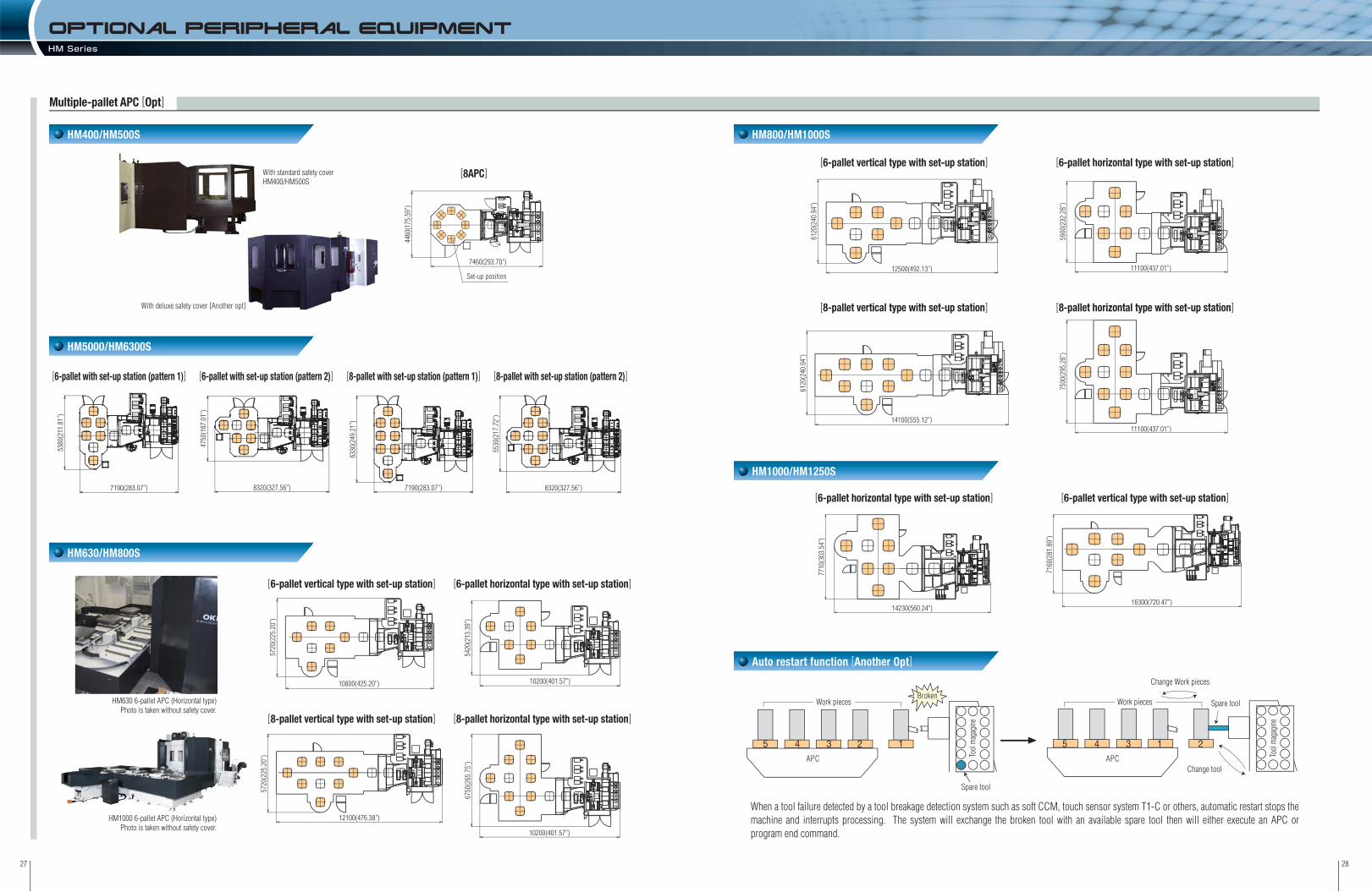
Auto restart function [Another Opt]
[6-pallet vertical type with set-up station] [6-pallet horizontal type with set-up station]
[8-pallet vertical type with set-up station] [8-pallet horizontal type with set-up station]
HM630/HM800S
OPTIONaL PERIPHERal equipmentHM Series
With standard safety coverHM400/HM500S
HM630 6-pallet APC (Horizontal type)Photo is taken without safety cover.
HM1000 6-pallet APC (Horizontal type)Photo is taken without safety cover.
With deluxe safety cover [Another opt]
Multiple-pallet APC [Opt]
HM5000/HM6300S
[6-pallet vertical type with set-up station] [6-pallet horizontal type with set-up station]
[8-pallet vertical type with set-up station] [8-pallet horizontal type with set-up station]
[6-pallet horizontal type with set-up station] [6-pallet vertical type with set-up station]
When a tool failure detected by a tool breakage detection system such as soft CCM, touch sensor system T1-C or others, automatic restart stops the machine and interrupts processing. The system will exchange the broken tool with an available spare tool then will either execute an APC or program end command.
[8APC]
Set-up position
7460(293.70")
4460
(175
.59"
)
10200(401.57’’)
5420
(213
.39’’
)
11100(437.01’’)
7500
(295
.28’’
)
14100(555.12’’)
6120
(240
.94’’
)
12500(492.13’’)
6120
(240
.94’’
)
11100(437.01’’)
5900
(232
.28’’
)
10200(401.57’’)
6750
(265
.75’’
)
10800(425.20’’)
5720
(225
.20’’
)
12100(476.38’’)
5720
(225
.20’’
)
14230(560.24’’)
7710
(303
.54’’
)
16300(720.47’’)
7160
(281
.89’’
)
7190(283.07’’)
6330
(249
.21’’
)
7190(283.07’’)
5380
(211
.81’’
)
[8-pallet with set-up station (pattern 1)][6-pallet with set-up station (pattern 1)] [8-pallet with set-up station (pattern 2)][6-pallet with set-up station (pattern 2)]
8320(327.56’’)
4750
(187
.01’’
)
5530
(217
.72’’
)8320(327.56’’)

3029
This screen enables the simple manual measurement using the touch sensor (option: T1-A or T1-B). You can move the sensor to the desired measuring point by handle mode then the machine starts the automatic measurement after the sensor contacts the workpiece. You can set the results of the measurement as the data for the desired workpiece coordinate system and tool offset number through the single key operation.
The HQ tuner provides the programmer a 10-step adjustment of parameters for hyper HQ control in accordance with processing conditions. It adjusts the hyper HQ control in accordance with the current process. For example, during roughing routines the programmer can place a higher priority on speed and in finishing routines a higher priority on dimensional accuracy at corners and circular arcs.
Programming support functions Maintenance functions
Original software HM Series
OKK’s exclusive control functions
T0 software [Opt]
HQ Tuner [Opt]
Reference plane
Width Diameter
Program Editor [F31i-B]Program editor allows you to edit programs stored in NC memory, from a data server (or hard disc) or memory card.
Tool Support [F31i-B]Now through a single set-up screen the tools number, description, schematic, and geometry are displayed. You can also perform the tool change commands and measurement cycle at the same set-up screen.
A large amount of machining programs can be transferred to the data server through the network connected to the host computer at high speed. The transferred machining programs are executed as the main programs or sub-programs (called up by using the M198 signal.)
Technologies for Reduced Setup and Unmanned Operation
Setup support functions
Tool setup screen
Display of details of alarms
Description of M signals
High-efficiency Control Technologies
F31i-B/FAi capability of processing fine line segments
High-efficiency Control Technologies
Data Server [Opt]
Tool length compensation amount measurement screen
Two programs can be displayed side by side.Characters in the program can be converted all at once. (Example: Changes F1000 to F1200.)Multiple-line data can be copied from other programs with ease.
Programs can be copied or deleted and program names can be changed easily with the Program Editor.The Program Editor’s multiple-file batch copy function enables to make a backup of the programs in the NC memory or hard disc easily with a memory card.
Adaptive control functionFeed override control range: 10 to 200%(Changeable with parameters)Alarms are output at the lower limit override value.Air-cut reduction functionFeed rates during non-cutting operation can be increased up to 200%.(Changeable with parameters)Tool failure monitoring functionSpecifications similar to the soft CCM.Continuous unmanned machining at the time of tool failure (option)Combined operation with the automatic restart function is possible.
The above values show (theoretical) maximum speeds for processing 1-mm-segment blocks constructing a straight line. Actual processing speeds depend on the type of the machine and NC data.By switching the right-side screen for reference use, a
list of M signals/G codes and information on tools in the magazine can be displayed.
Help Guidance [F31i-B]The screen will display detailed information regarding the machine alarm and will explain how to recover the machine from the problem. This screen will also display a list of G-codes and a description of M signals.
Soft CCM [Opt]The Soft CCM monitors the spindle load meter, and stops operation when the meter value exceeds the preset value (set by M signal or set for each of the T numbers through setting screen) and generation of abnormal tool load is determined which is convenient for unmanned operation at night.
Soft AC [Opt]The soft AC function applies the feed rate override control automatically so that the value of the spindle load meter does not change significantly.This helps to prevent damages of tools caused by overload and improve cutting efficiency.
Hyper HQ Control [Opt]High-speed processing is enabled by improved capability of processing fine line segment toolpaths.
15 (591 ipm)
30 (1181 ipm)
150 (5906 ipm) -
Fine line segment data processing speed (m/min) Instruction methodType
Without Hyper HQ controlHyper HQ control mode A
Hyper HQ control mode B
ON: G05.1Q1; OFF: G05.1Q0
ON: G05.1Q1; OFF: G05.1Q0
F31i-B FAi
Transferring machiningprograms at high speed
Coordinate rotation Distance

3231
FANUC Controller F31i-B
No. of controlled axes: 4 axes (X, Y, Z, B)No. of simultaneously controlled axes: 3 axes (4 axes for BRT specification)Least input increment: 0.001mm / 0.0001”Max.programmable dimension: ±999999.999mm / ±39370.0787”Absolute / Incremental command: G90 / G91Decimal point input / Pocket calculator type decimal point inputInch / Metric conversion: G20 / G21Program code: ISO / EIA automatic discriminatonProgram format: FANUC standard formatNano interpolation (internal)Positioning: G00Linear interpolation: G01Circular interpolation: G02 / G03 (CW / CCW), including radius designationCutting feed rate: 6.3-digit F-code, direct commandDwell: G04Manual handle feed: manual pulse generator 1 set(0.001, 0.01, 0.1mm)Rapid traverse override: 0 / 1 / 10 / 25 / 50 / 100%Cutting feed rate override: 0 to 200% (every 10%)Feed rate override cancel: M49 / M48Rigid tapping: G84, G74 (Mode designation: M29)Part program storage capacity: 160m[64KB]No. of registered programs: 120Part program editingBackground editingExtended part program editing10.4” color LCDClock functionMDI (Manual Data Input) operationMemory card interfaceSpindle function: 5-digit S-code direct commandSpindle speed override: 50 to 150% (every 5%)Tool function: 4-digit T-code direct commandATC tool registrationAuxiliary function: 3-digit M-code programmingMultiple M-codes in 1 block: 2 codes (HM400/HM500S/HM5000/HM6300S: 3 codes (Max. 20 settings))
Tool length offset: G43, G44/G49Tool diameter and cutting edge R compensation: G41, G42/G40Tool offset sets: 99 sets in totalTool offset memory CManual reference position returnAutomatic reference position return: G28/G292nd reference position return: G30Reference position return check: G27Automatic coordinate system settingCoordinate system setting: G92Machine coordinate system: G53Workpiece coordinate system: G54 to G59Local coordinate system: G52Program stop: M00Optional stop: M01Optional block skip: /Dry runMachine lockZ-axis feed cancelAuxiliary function lockGraphic displayProgram number search
Sequence number searchProgram restartCycle startAuto restartSingle blockFeed holdManual absolute on/off: parameterSub program controlCanned cycle: G73, G74, G76, G80 to G89Mirror image function: parameterAutomatic corner overrideExact stop check/modeProgrammable data input: G10Backlash compensation for each rapid traverse and cutting feedSmooth backlash compensationMemory pitch error compensation (interpolation type)Skip functionTool length manual measurementEmergency stopData protection keyNC alarm display / alarm history displayMachine alarm displayStored stroke check 1Stored stroke check 2, 3Load monitorSelf-diagnosisAbsolute position detectionManual guide i (Basic)
15” color LCDAdditional one axis control: name of axis(A, B, C, U, V, W) *Additional two axes control: name of axis(A, B, C, U, V, W) *No. of simultaneously controlled axes: 5 axes *Least input increment: 0.0001mm / 0.00001”FS15 tape formatUnidirectional positioning: G60Helical interpolation PK1Cylindrical interpolationHypothetical axis interpolationSpiral/Conical interpolationSmooth interpolation (Hyper HQ control B mode is required)NURBS interpolation (Hyper HQ control B mode is required)Involute interpolationOne-digit F code feedHandle feed 3 axes(Standard pulse handle is removed)Part program storage capacity: 320m[128KB](250 in total)Part program storage capacity: 640m[256KB](500 in total)Part program storage capacity: 1280m[512KB](1000 in total) PK1Part program storage capacity: 2560m[1MB](1000 in total)Part program storage capacity: 5120m[2MB](1000 in total)Part program storage capacity: 10240m[4MB](1000 in total)Part program storage capacity: 20480m[8MB](1000 in total)RS232C interface: RS232C-1CHData server: ATA card (1GB) PK2Data server: ATA card (4GB)Spindle contour control (Cs contour control)Tool position offset
3-dimensional cutter compensationTool offset sets: 200 sets in total PK1Tool offset sets: 400 sets in totalTool offset sets: 499 sets in totalTool offset sets: 999 sets in totalAddition of workpiece coordinate system (48 sets in total): G54.1 P1 to P48 PK1Addition of workpiece coordinate system (300 sets in total): G54.1 P1 to P300Machining time stampAddition of optional block skip: 9 in totalTool retract and returnSequence number comparison and stopManual handle interruptionProgrammable mirror image PK1Optional chamfering / corner RCustom macro PK1Interruption type custom macroAddition of custom macro common variables: 600Figure copyCoordinate system rotation: G68, G69Scaling: G50, G51Chopping (Axis control by PMC)PlaybackAutomatic tool length measurement: G37 / G37.1Tool life management: 256 sets in total PK1Addition of tool life management sets: 1024 sets in totalHigh-speed skipRun hour and parts count display PK1Manual guide i (Milling cycle)
Machining support integrated software (including Help guidance, etc.) STDTool support STDProgram editor STDEasyPRO STDWork manager OPHQ control STDHyper HQ control mode A OPHyper HQ control mode B PK2 OPHyper HQ value kit (including the items with “PK2”) OPNC option package (including the items with “PK1”) OPSpecial canned cycle (including circular cutting) OPCycle mate F OPSoft scale Ⅱm STDTouch sensor T0 software OPTool failure detection system (Soft CCM) OPAdaptive control (Soft AC) OPAutomatic restart at tool damage OP
*F31i-B5 (Windows CE-installed Open CNC) controller is required STD: Standard OP: Option
No. of controlled axes: 4 axes (X, Y, Z, B)No. of simultaneously controlled axes: 3 axes (4 axes for BRT specification)Least input increment: 0.001mm / 0.0001”Max.programmable dimension: ±999999.999mm / ±39370.0787”Absolute / Incremental command: G90 / G91Decimal point input / Pocket calculator type decimal point inputInch / Metric conversion: G20 / G21Program code: ISO / EIA automatic discriminatonProgram format: FANUC standard formatNano interpolation(internal)Positioning: G00Linear interpolation: G01Circular interpolation: G02 / G03 (CW / CCW), including radius designationUnidirectional positioning: G60Helical interpolationCylindrical interpolationCutting feed rate: 6.3-digit F-code, direct commandDwell: G04Manual handle feed: manual pulse generator 1 set (0.001, 0.01, 0.1mm)Rapid traverse override: 0 / 1 / 10 / 25 / 50 / 100%Cutting feed rate override: 0 to 200% (every 10%)Feed rate override cancel: M49 / M48Rigid tapping: G84, G74 (Mode designation: M29)One-digit F code feedInverse time feedPart program storage capacity: 1280m[512KB]No. of registered programs: 400Part program editingBackground editingExtended part program editing10.4” color LCDClock functionMDI(Manual Data Input) operationRun hour and parts count displayMemory card interfaceSpindle function: 5-digit S-code direct commandSpindle speed override: 50 to 150% (every 5%)Tool function: 4-digit T-code direct commandATC tool registrationAuxiliary function: 3-digit M-code programmingMultiple M-codes in 1 block: 3 codes (Max. 20 settings)Tool length offset: G43, G44/G49Tool diameter and cutting edge R compensation: G41, G42/G40Tool offset sets: 400 sets in totalTool offset memory CTool position offsetManual reference position returnAutomatic reference position return: G28/G292nd reference position return: G30Reference position return check: G27Automatic coordinate system settingCoordinate system setting: G92Machine coordinate system: G53Workpiece coordinate system: G54 to G59Local coordinate system: G52Addition of workpiece coordinate system (48 sets in total): G54.1 P1 to P48Program stop: M00Optional stop: M01
FANUC Controller FAi
HQ control STDHyper HQ control mode A OPSoft scale Ⅱm STDSpecial canned cycle (including circular cutting) OPTouch sensor T0 software OPTool failure detection system (Soft CCM) OPAdaptive control (Soft AC) OPAutomatic restart at tool damage OP
ControllerHM Series
Standard SpecificationStandard SpecificationStandard Specification Standard Specification Original OKK SoftwareOptional Specification
STD: Standard OP: Option
Optional block skip: /Addition of optional block skip: 9 in totalDry runMachine lockZ-axis feed cancelAuxiliary function lockGraphic displayProgram number searchSequence number searchProgram restartCycle startAuto restartSingle blockFeed holdManual absolute on/off: parameterSequence number comparison and stopManual handle interruptionSub program controlCanned cycle: G73, G74, G76, G80 to G89Mirror image function: parameterAutomatic corner overrideExact stop check/modeProgrammable data input: G10Scaling: G50, G51Custom macroInterruption type custom macroAddition of custom macro common variables: 600Programmable mirror imageCoordinate system rotation: G68, G69Optional chamfering / corner RManual guide i (Basic)Backlash compensation for each rapid traverse and cutting feedMemory pitch error compensationSkip functionTool length manual measurementTool life management: 128 sets in totalEmergency stopData protection keyNC alarm display / alarm history displayMachine alarm displayStored stroke check 1Stored stroke check 2, 3Load monitorSelf-diagnosisAbsolute position detection
Additional one axis control: name of axis (A, C, U, V, W) (No. of simultaneously controlled axes: 4 axes)
Additional two axes control: name of axis (A, C, U, V, W) (No. of simultaneously controlled axes: 4 axes)
FS11 tape formatPart program storage capacity: 5120m[2MB](400 in total)Data server: ATA card (1GB)Spindle contour control (Cs contour control)Manual guide i (Milling cycle)High-speed skipRS232C interface: RS232C-1CH
Optional Specification Original OKK Software
Optional Specification
(Windows CE-installed Open CNC)

3433
Pallet Dimensions XYZ axes travel diagrams
Front ViewTravel on X axis (Column: right/left)
Travel on Y axis (Spindle head: up/down)
Travel on Z axis (Table: back/forth)
Distance from table top surface to spindle center
Distance from table center to spindle nose
Pallet work surface area
Max. weight loadable on pallet
Pallet top surface configuration
Minimum indexable angle of table
Table index time (for indexing 90 degrees)
Spindle speed
Number of spindle speed change steps
Spindle inner taper
Spindle bearing inner diameter
Rapid traverse rate
Cutting feed rate
Type of tool shank
Type of pull stud
Tool storage capacity
Maximum tool diameter
Maximum tool length (from the gauge line)
Maximum tool weight
Maximum tool moment
Tool selection method
Tool change time (cut-to-cut)
Pallet change method
Pallet change time (JIS evaluation time)
Spindle motor
Feed motor (X,Y,Z,B)
Hydraulic pump motor
Motor of oil cooler for spindle and feed system(compression/discharge)
Coolant pump motor
Power supply AC200V±10% 50/60±1Hz AC220V±10% 60±1Hz*4
Compressed air supply
Hydraulic unit tank capacity
Spindle and feed system cooling oil tank capacity
Coolant tank capacity
Machine height
Required floor space
Machine weight
Operating environment temperature
mm
mm
mm
mm
mm
mm
kg
degsec
min-1
mm
m/min
mm/min
tool
mm
mm
kg
N.m
sec
sec
AC, kW
kW
kW
kW
kW
kVA
MPa, ℓ/min [ANR]
ℓℓℓ
mm
mm
kg
°C
*1 BRT: Built-in rotary table minimum indexing 0.001° IT: Index table minimum indexing 1° *2 Available under the HQ or hyper HQ control. *3 The number of stored tools refers a total number of tools including the one installed on the spindle i.e. subtract one from the above for actual number of tools stored in the tool magazine.*4 When the supply voltage is 220VAC, the supply frequency of 60Hz only is applicable.*5 Purity of compressed air should be class 3.5.4 or higher class of ISO 8573-1/JIS B8392-1 standard.*6 Specified is the compressed air supply flow rate for standard specification machines. When optional specifications such as an air blow nozzle are added, add the corresponding air supplyrequirement.
*edgelocater[Opt]
Item
Standard Specifications Machine Dimensions mm(in)
CA
CA
B
BD
25-M16 screw
C
A
AB
B
12(0
.47”)
18(0.71”)H8
20(0
.79”)
30(1.18)
Yst.6
20(2
4.41”
)D
315(
12.40
”)31
5(12
.40”)
Xst.6
30(2
4.80”
)
Zst.710(27.95”)
Max
. wor
kpiec
e heig
ht: B
ø680(26.77”): HM400/40, HM500S/40
450(17.72”): HM400/50, HM500S/50
C
150(5.91”)
150(
5.91”
)
E
F (G)
HCollision area
SPECIFICaTIONS HM400/HM500SHM Series HM400/HM500S
HM400/40 HM500S/40 HM400/50 HM500S/50
630 (24.80”)
620 (24.41”)
710 (27.95”)
150~860(5.91”~33.86”)
(Uniform load) 450 (992lbs)
25×M16tap
BRT 0.001 / IT[Opt] 1*1
BRT 0.5 / IT[Opt] 1.9
Electric 2-step speed change (MS)
54 (2,126 ipm)
1~40,000 (0.04~1574 ipm)*2
40*3
400 (15.75”)
Address fixed random system
Direct turn
9.5
FANUC 5.5 (7.4HP) / 5.5 (7.4HP) / 4.5 (6.0HP) /BRT: 4.5 (6.0HP) (IT[Opt]: 4.5 (6.0HP))
1.5 (2.0HP)
1.1 (1.5HP) / 0.4 (0.5HP)
50Hz: 0.7 (0.9HP) 60Hz: 1.2 (1.6HP)
0.4~0.6*5, 500*6 (58~87 psi, 132 gal/min)
20 (5.3 gal)
20 (5.3gal)
480 (127 gal)
Refer to the floor space drawing.
5~40
80~700 (3.15”~27.55”)
� 400 (15.75”)
12,000 (26,455 lbs)
50~670 (1.97”~26.38”)
� 500 (19.69”)
12,200 (26,896 lbs)
80~700 (3.15”~27.55”)
� 400 (15.75”)
12,500 (27,557 lbs)
50~670 (1.97”~26.38”)
� 500 (19.69”)
12,700 (27,998 lbs)
35~10,000
7/24 taper, No.40
ø80 (3.15”)
JIS B 6339 BT40
MAS403 P40T-1 (MASI)
ø82 (3.23”) / ø160 (6.30”) without tool in adjacent pot
12 (26 lbs) with slow ATC cycle
9.8 (7.2 ft . lbs)
3.3
FANUC 37 (50HP)/26 (35HP) / 22 (30HP) (25%ED/30min/cont. rating)
FANUC 56
2844 (111.97”)
35~12,000
7/24 taper, No.50
ø100 (3.94”)
JIS B 6339 BT50
OKK only 90°
ø115 (4.53”) / ø250 (9.84”) without tool in adjacent pot
25 (55 lbs) with slow ATC cycle
29.4 (21.7 ft . lbs)
4.2
FANUC 30 (40HP) / 25 (34HP) (30min/cont. rating)
FANUC 62
2970 (116.93”)
200(
7.87
”): H
M40
0/40
, HM
500S
/40
Dimensions and shape of workpiece :Blue-colored section: Dimensions and shape for HM400/40 and HM500S/40Red-colored section: Dimensions and shape for HM400/50 and HM500S/50Black-colored section: Dimensions and shape being common to the machines
Restriction on Tool
MAX 400(15.75”)MAX 160(6.30”)
MAXø230(9.06”)
MAXø115(4.53”)
MIN 46(1.81”)
MAXø250(9.84”)
HM400/50, HM500S/50HM400/40, HM500S/40
ø40(
1.57”
)ø8
2(3.2
3”)
ø150
(5.91
”)with toolin adjacent pot
with toolin adjacent potwithout tool in adjacent pot
400(15.75”) 150(5.91”)
MIN 40(1.57”)50(1.97”)
350(13.78”)
MAX160(6.30”)
A
400(15.75”)
500(19.69”)
400(15.75”)
500(19.69”)
B
900(35.43”)
870(34.25”)
870(34.25”)
840(33.07”)
C
700(27.56”)
670(26.38”)
670(26.38”)
640(25.20”)
E
160(6.30”)
190(7.48”)
160(6.30”)
190(7.48”)
F
200(7.87”)
250(9.84”)
200(7.87”)
250(9.84”)
G
50(1.97”)
61(2.40”)
50(1.97”)
61(2.40”)
H
110(4.33”)
90(3.54”)
110(4.33”)
90(3.54”)
D
80(3.15”)
50(1.97”)
50(1.97”)
20(0.79”)
XYZ axis travel diagrams
HM400
HM500S
HM400(T-slot)
HM500S(T-slot)
HM400
HM500S
HM400(T-slot)
HM500S(T-slot)
A
400(15.8”)
500(19.7”)
400(15.8”)
500(19.7”)
B
50(1.97”)
65(2.56”)
50(1.97”)
65(2.56”)
C
80(3.15”)
100(3.94”)
80(3.15”)
100(3.94”)
D
130(5.12”)
160(6.30”)
160(6.30”)
190(7.48”)
Pallet dimensions
Tap specification [Std] T-slot specification [Opt]
Hydraulic unit (installed separately)
5225(205.71”)[5425(213.58”)]
4255(167.52”)[4355(171.46”)]270(10.63”)
2495
(98.2
3”)[2
895(
113.9
8”)]6
00(2
3.62”
)
3770
(148
.43”)[
4343
(170
.98”)]
675(
26.57
”)
2685
(105
.71”)
[900(35.43)]
[725
(28.5
4”)]
[723
(28.4
6”)]
700(27.56”)
[170(6.69”)]
Floor Space[ ]: Dimensions of HM400/50 and HM500S/50
without tool in adjacent pot
mm(in)
mm(in)
[ ]: Dimensions of HM400/50 and HM500S/50
A
Oil cooler(installed separately)
Max. work
piece d
iameter
: 700(2
7.56
Max. work
piece d
iameter
: 700(2
7.56”)
Max. work
piece d
iameter
: 700(2
7.56”)
Lift up chip conveyor [Opt]
245(9.65”)[250(9.84”)]
2844
(111
.97”)
2495(98.23”)[2895(113.98”)](935(36.81”))
[(535(21.06”))]3675(144.69”)[3680(144.88”)]
(Opti
onal
60M
G sp
ecific
ation
) 30
65(1
20.67
”)(60
MG)
[297
0(11
6.93”
)(40M
G)]
2480
(97.6
4”)
68(2.68”): HM400/5018(0.71”): HM500S/50
ø700(27.56”)

3635
Travel on X axis (Column: right/left)
Travel on Y axis (Spindle head: up/down)
Travel on Z axis (Table: back/forth)
Distance from table top surface to spindle center
Distance from table center to spindle nose
Pallet work surface area
Max. weight loadable on pallet
Pallet top surface configuration
Minimum indexable angle of table
Table index time (for indexing 90 degrees)
Spindle speed
Number of spindle speed change steps
Spindle inner taper
Spindle bearing inner diameter
Rapid traverse rate
Cutting feed rate
Type of tool shank
Type of pull stud
Tool storage capacity
Maximum tool diameter
Maximum tool length (from the gauge line)
Maximum tool weight
Maximum tool moment
Tool selection method
Tool change time (cut-to-cut)
Pallet change method
Pallet change time (JIS evaluation time)
Spindle motor (30min/cont. rating)
Motor for ATC (Automatic Tool Changer)
Feed motor (X,Y,Z,B)
Hydraulic pump motor
Motor of oil cooler for spindle and feed system (compression/discharge)
Coolant pump motor
Power supply AC200V±10% 50/60±1Hz AC220V±10% 60±1Hz*4
Compressed air supply
Hydraulic unit tank capacity
Spindle and feed system cooling oil tank capacity
Magazine lubricating oil tank capacity
Coolant tank capacity
Machine height
Required floor space
Machine weight
Operating environment temperature
mm
mm
mm
mm
mm
mm
kg
°
sec
min-1
mm
m/min
mm/min
tool
mm
mm
kg
N.m
sec
sec
AC, kW
kW
kW
kW
kW
kW
kVA
MPa, ℓ/min [ANR]
ℓℓℓℓ
mm
mm
kg
°C
80~830 (3.15”~32.68”)
� 500 (19.69”)
(Uniform load) 800 (1763 lbs)
14,000 (30,864 lbs)
50~800 (1.96”~31.50”)
� 630 (24.80”)
(Uniform load) 700 (1543 lbs)
14,300 (31,525 lbs)
*1 BRT: Built-in rotary table minmum indexing 0.001° IT: Index table minimum indexing 1° *2 Available under the HQ or hyper HQ control.*3 The number of stored tools refers a total number of tools including the one installed on the spindle i.e. subtract one from the above for actual number of tools stored in the tool magazine.*4 When the supply voltage is 220VAC, the supply frequency of 60Hz only is applicable.*5 Purity of compressed air should be class 3.5.4 or higher class of ISO 8573-1/JIS B8392-1 standard.*6 Specified is the compressed air supply flow rate for standard specification machines. When optional specifications such as an air blow nozzle are added, add the corresponding air supply requirement.
Item
Standard Specifications Machine Dimensions mm(in)
800 (31.50”)
750 (29.53”)
880 (34.65”)
70~950 (2.76”~37.40”)
24×M16tap
BRT 0.001 / IT [Opt] 1*1
BRT 0.5 / IT [Opt] 1.7
35~12,000
Electric 2-step speed change (MS)
7/24 taper, No.50
ø100 (3.94”)
60 (2,362 ipm)
1~40,000 (0.04~1574 ipm)*2
JIS B 6339 BT50
OKK only 90°
40*3
ø115 (4.53”) / ø270 (10.63”) without tool in adjacent pots
500 (19.69”)
25 (55 lbs)
29.4 (21.68 ft . lbs)
Address fixed random system
4.3
Direct turn
12
FANUC 30 (40HP) / 25 (34HP)
0.75 (1HP)
FANUC 5.5 (7.4HP) / 5.5 (7.4HP) / 5.5 (7.4HP) / BRT: 4.5 (6.0HP) (IT[Opt]: 1.6 (2.1HP))
1.5 (2.0HP)
1.1 (1.5HP) / 0.4 (0.5HP)
50Hz: 0.7 (0.9HP) 60Hz: 1.2 (1.6HP)
FANUC 59
0.4~0.6*5, 500*6 (58~87 psi, 132 gal/min)
20 (5.3 gal)
20 (5.3gal)
1 (0.3 gal)
720 (190 gal) (Option for the lift up type chip conveyor specification)
3,125 (123.03”)
3,945×5,230 (155.31”×205.91”) (Option for the lift up type chip conveyor specification)
5~40
SPECIFICaTIONS HM5000/HM6300SHM Series HM5000/HM6300S
Pallet Dimensions
Floor Space
XYZ axes travel diagrams
Front View
Restriction on Tool
(Opt
iona
l 60M
G sp
ecifi
catio
n) 4
140(
162.
99’’)
Lift-up chip conveyor [Opt]
High pressurecoolant unit [Opt]
4795(188.78’’)
3135
(123
.43’’
)83
5(3
2.87
’’)
4770
(187
.80’’
)
435(17.13’’) 990(38.98’’)
6220(244.88’’)
3655
(143
.90’’
)80
0(31.5
0’’)47
70(1
87.8
0’’)
3600(141.73’’)(Maintenance for Coil-type chip conveyor)
Lubricating oil temperature controller
800
(31.
50’’)
A
70(2.76’’)70(2.76’’) 880(34.65’’)
ø800(31.50’’)Y-axis Shutter
Zst.880(34.65’’)
E
18(0.71’’) H8
20(0
.79’’
)12
(0.4
7’’)
30(1.18’’)
C
T-slot specification [Opt]
A
CA
B
BD
CA
AB
B
24-M16 screwø50(1.97’’)H7
400(1
5.75’’)
400(1
5.75’’)
Xst.8
00(3
1.50
’’)
Yst.7
50(2
9.53
’’)D
C
B
MAX ø270(10.63’’)
MAXø230(9.06’’)
3945(155.31’’)3135(123.43’’)
520(20.47’’)
290(11.42’’)
2770
(109
.06’’
)
HM5000
HM6300S
A
500(19.69”)
630(24.8”)
B
1090(42.91”)
1060(41.73”)
C
830(32.68”)
800(31.5”)
E
271(10.67”)*1
336(13.23”)*2
D
80(3.15”)
50(1.97”)
XYZ axis travel diagrams
HM5000
HM6300S
A
500(19.69”)
630(24.80”)
B
60(2.36”)
70(2.76”)
C
100(3.94”)
125(4.92”)
D
130(5.12”)
160(6.30”)
Pallet dimensions
Notes: Tap and T-slot are same dimensions.
*1 At B-axis rotated 0°/90°/180°/270°: 250mm (9.84”). *2 At B-axis rotated 0°/90°/180°/270°: 315mm (12.40”).
Notes: Tap and T-slot are same dimensions.
mm(in)
mm(in)
Tap specification [Std]
Opening Door850(33.46’’)
355(1
3.98’’)
MAX ø230(9.06’’)MAX ø115(4.53’’)
MIN 46(1.81’’)MIN 56(2.20’’)
MAX 485(19.09’’)MAX 500(19.69’’)
800(31.50’’)(Max. workpiece diameter)
285(11.22’’)
with tool in adjacent potwithout tool in adjacent pot

3837
Travel on X axis (Column: right/left)
Travel on Y axis (Spindle head: up/down)
Travel on Z axis (Table: back/forth)
Distance from pallet top surface to spindle center
Distance from pallet center to spindle nose
Pallet work surface area
Max. weight loadable on pallet
Pallet top surface configuration
Minimum indexable angle of table
Table index time (for indexing 90 degrees)
Spindle speed
Number of spindle speed change steps
Spindle inner taper
Spindle bearing inner diameter
Rapid traverse rate
Cutting feed rate
Type of tool shank
Type of pull stud
Tool storage capacity
Maximum tool diameter
Maximum tool length (from the gauge line)
Maximum tool weight
Maximum tool moment
Tool selection method
Tool change time (cut-to-cut)
Pallet change method
Pallet change time (JIS evaluation time)
spindle motor (25%ED/30min/cont. rating)
Motor for tool clamp/unclamp unit
Feed motor (X, Y, Z, B)
Hydraulic pump motor
Motor of oil cooler for spindle and feed system (compression/discharge)
Coolant pump motor
Motor for APC unit
Power supply 200VAC ±10% 50/60 ±1Hz 220VAC ±10% 60 ±1Hz*4
Compressed air supply
Hydraulic unit tank capacity
Spindle and feed system cooling oil tank capacity
Magazine lubricating oil tank capacity
Coolant tank capacity
Machine height
Required floor space
Machine weight
Operating environment temperature
mm
mm
mm
mm
mm
mm
kg
°sec
min-1
mm
m/min
mm/min
tool
mm
mm
kg
sec
sec
AC, kW
kW
kW
kW
kW
kW
kW
kVA
MPa, ℓ/min [ANR]
ℓℓℓℓ
mm
mm
kg
°C
900 (35.43”)
80~980 (3.15”~38.58”)
200~1100 (7.87”~43.31”)
� 630 (24.80”)
(Uniform load) 1300 (2866 lbs)
18,000 (39700 lbs)
880 (34.65”)
60~960 (2.36”~37.80”)
220~1100 (8.66”~43.31”)
� 800 (31.50”)
(Uniform load) 1200 (2645 lbs)
18,500 (40800 lbs)
*1 BRT: Built-in rotary table minmum indexing 0.001° IT: Index table minimum indexing 1° *2 Available under the HQ or hyper HQ control.*3 The number of stored tools refers a total number of tools including the one installed on the spindle i.e. subtract one from the above for actual number of tools stored in the tool magazine.*4 When the supply voltage is 220VAC, the supply frequency of 60Hz only is applicable.*5 Purity of compressed air should be class 3.5.4 or higher class of ISO 8573-1/JIS B8392-1 standard.*6 Specified is the compressed air supply flow rate for standard specification machines. When optional specifications such as an air blow nozzle are added, add the corresponding air supply requirement.
Item
Standard Specifications Dimentions mm(in)
1050 (41.34”)
900 (35.43”)
24xM16 tap
BRT 0.001 / IT [Opt] 1*1
BRT 0.6 / IT [Opt] 1.7
35~12,000
Electric 2-step speed change (MS)
7/24 taper, No.50
ø100 (3.94”)
54 (2,126 ipm)
1~40,000 (0.04~1574 ipm)*2
JIS B 6339 BT50
OKK only 90º
40*3
ø115 (4.53”) / ø270 (10.63”) without tool in adjacent pots
500 (19.69”)
25 (55 lbs)
29.4 (21.7 ft . lbs)
Address fixed random system
4.4
Direct turn
15.0
FANUC 45 (60HP) / 30 (40HP) / 26 (35HP)
0.75 (1.0HP)
FANUC 5.5 (7.4HP) / 5.5 (7.4HP) / 5.5(7.4HP) / BRT: 4.5 (6.0HP) (IT[Opt]: 2.7 (3.6HP))
1.5 (2.0HP)
1.7(2.3 HP) / 0.75 (1.0 HP)
50Hz: 0.7 (0.9HP) 60Hz: 1.2 (1.6HP)
0.75 (1.0 HP)
FANUC 65
0.4~0.6*5, 500*6 (58~87 psi, 132 gal/min)
20 (5.3 gal)
70 (18.5 gal)
1 (0.3 gal)
400 (106 gal)
3,430 (135.04”)
3,420x5,450 (134.65”x214.57”)
5~40
SPECIFICaTIONS HM630/HM800SHM Series HM630/HM800S
Pallet Dimensions
Floor Space
XYZ axes travel diagrams
Restriction on Tool
Front View
HM630: Tap and T-slot are same dimensions.
HM630: Tap and T-slot are same dimensions.
MIN 56(2.20")MIN 46(1.81”)
MAX ø270(10.63”)
MAX ø115(4.53”) MAX
ø230(9.06”)
MAX 500(19.69”)
(Note 1)For executing the APC operation, the loaded workpiece must not exceed the specified maximum APC turning diameter.
Max
. wor
kpiec
e heig
ht: F
APCturningcenter
G
M I
Yst.9
00(3
5.43”
)
BD
Zst.CE
Xst.1
050(
41.34
”)52
5(20
.67”)
525(
20.67
”)
J (K)L
A
600(23.62”)
H
(520(20.47”))
(526
(20.7
1”))
(526
(20.7
1”))
Collision area
5450(214.57”)
5055
(199
.02”)
(Opti
onal
60M
G sp
ecific
ation
)437
0(17
2.05”
)
(Opti
onal
75-m
/min
rapid
trave
rse ra
te sp
ecific
ation
)379
6(14
9.45”
)
(Opti
onal
ceilin
g sho
wer s
pecif
icatio
n)35
35(1
39.17
”)
3430
(135
.04”)
3670(144.49”)
3000
(118
.11”)
D
A
A
B
BC
C
ø50(1.97”)H724-M16 screw
A
A
B
BC
18(0.71”)H8
30(1.18”)
12(0
.47”)
20(0
.79”)
HM630
HM800S
HM800S(T-slot)
A
630(24.8”)
800(31.5”)
800(31.50”)
B
70(2.76”)
100(3.94”)
100(3.94”)
C
125(4.92
160(6.30”)
160(6.30”)
D
160(6.30”)
180(7.09”)
200(7.87”)
Pallet dimensions
HM630
HM800S
HM800S(T-slot)
A
630(24.8”)
800(31.5”)
800(31.50”)
B
200(7.87”)
220(8.66”)
220(8.66”)
C
900(35.43”)
880(34.65”)
880(34.65”)
E
200(7.87”)
220(8.66”)
220(8.66”)
F
1220(48.03”)
1200(47.24”)
1180(46.46”)
G
980(38.58”)
960(37.80”)
940(37.01")
H
80(3.15”)
60(2.36”)
40(1.57”)
I
220(8.66”)
300(11.81”)
300(11.81”)
J
315(12.4”)
400(15.75”)
400(15.75")
K
84(3.31”)
100(3.94”)
100(3.94”)
L
105(4.13”)
120(4.72”)
120(4.72”)
M
150(5.91”)
150(5.91”)
170(6.69”)
D
900(35.43”)
880(34.65”)
880(34.65”)
XYZ axis travel diagrams
with tool in adjacent potwithout tool in adjacent pot
mm(in)
mm(in)
T-slot specification [Opt]Tap specification [Std]
Max. work
piece
diamete
r: 1110
(43.70
”)(Note
1)
Max. work
piece
diamete
r: 1110
(43.70
”)(Note
1)
Max. work
piece
diamete
r: 1110
(43.70
”)(Note
1)
Max. APC tur
ning d
iameter
: ø2240
(88.19
”)
Max. APC tur
ning d
iameter
: ø2240
(88.19
”)
Max. APC tur
ning d
iameter
: ø2240
(88.19
”)
(526
(20.7
1”))
(488(19.21”))(488(19.21”))(488(19.21”))

4039
Travel on X axis (Column: right/left)
Travel on Y axis (Spindle head: up/down)
Travel on Z axis (Table: back/forth)
Distance from pallet top surface to spindle center
Distance from pallet center to spindle nose
Pallet work surface area
Max. weight loadable on pallet
Pallet top surface configuration
Minimum indexable angle of table
Table index time (for indexing 90 degrees)
Spindle speed
Number of spindle speed change steps
Spindle inner taper
Spindle bearing inner diameter
Rapid traverse rate
Cutting feed rate
Type of tool shank
Type of pull stud
Tool storage capacity
Maximum tool diameter
Maximum tool length (from the gauge line)
Maximum tool weight
Maximum tool moment
Tool selection method
Tool change time (cut-to-cut)
Pallet change method
Pallet change time (JIS evaluation time)
spindle motor (30min/cont. rating)
Motor for tool clamp/unclamp unit
Feed motor (X, Y, Z, B)
Hydraulic pump motor
Motor of oil cooler for spindle and feed system (compression/discharge)
Coolant pump motor
Motor for APC unit
Power supply 200VAC ±10% 50/60 ±1Hz 220VAC ±10% 60 ±1Hz*4
Compressed air supply
Hydraulic unit tank capacity
Spindle and feed system cooling oil tank capacity
Magazine lubricating oil tank capacity
Coolant tank capacity
Machine height
Required floor space
Machine weight
Operating environment temperature
mm
mm
mm
mm
mm
mm
kg
°
sec
min-1
mm
m/min
mm/min
tool
mm
mm
kg
sec
sec
AC, kW
kW
kW
kW
kW
kW
kW
kVA
Pa, ℓ/min [ANR]
ℓ
ℓ
ℓ
ℓ
mm
mm
kg
1050 (41.34”)
60~1160 (2.36”~45.67”)
200~1250 (7.87”~49.21”)
� 800 (31.50”)
(Uniform load) 2000 (4400 lbs)
IT 4.5 / BRT [Opt] 1.2
19.0
24,500 (54,000 lbs)
1000 (39.37”)
30~1130 (1.18”~44.49”)
250~1250 (9.84”~49.21”)
� 1000 (39.37”)
(Uniform load) 2500 (5500 lbs)
IT 5.5 / BRT [Opt] 1.2
21.0
25,000 (55,000 lbs)
*1 BRT: Built-in rotary table minmum indexing 0.001° IT: Index table minimum indexing 1° *2 Available under the HQ or hyper HQ control.*3 The number of stored tools refers a total number of tools including the one installed on the spindle i.e. subtract one from the above for actual number of tools stored in the tool magazine.*4 When the supply voltage is 220VAC, the supply frequency of 60Hz only is applicable.*5 Purity of compressed air should be class 3.5.4 or higher class of ISO 8573-1/JIS B8392-1 standard.*6 Specified is the compressed air supply flow rate for standard specification machines. When optional specifications such as an air blow nozzle are added, add the corresponding air supply requirement.
Item
Standard Specifications Dimentions mm(in)
1400 (55.12”)
1100 (43.31”)
24xM16 tap
IT 1/ BRT [Opt] 0.001*1
35~8,000
Electric 2-step speed change (MS)
7/24 taper, No.50
ø100 (3.94”)
48 (1,889 ipm)
1~40,000 (0.04~1574 ipm)*2
JIS B 6339 BT50
OKK only 90º
40*3
ø115 (4.53”) / ø270 (10.63”) without tool in adjacent pots
500 (19.69”)
25 (55 lbs)
29.4 (21.7 ft . lbs)
Address fixed random system
5.8
Direct turn
FANUC 30 (40HP) / 25 (34HP)
0.75 (1.0HP)
FANUC 5.5 (7.4HP) / 9.0 (12.1HP) / 6.0 (8.0HP) / IT: 2.7 (3.6HP) (BRT[Opt]: 4.5 (6.0HP))
1.5 (2.0HP)
1.7 (2.3HP) / 0.75 (1.0HP)
50Hz: 0.7 (0.9HP) 60Hz: 1.2 (1.6HP)
0.75 (1.0HP)
FANUC 61
0.4~0.6*5, 500*6 (58~87 psi, 132 gal/min)
20 (5.3 gal)
72 (19 gal)
1 (0.3 gal)
800 (211 gal)
4,000 (157.48”)
3,682x6,395 (144.96”x251.77”)
5~40
SPECIFICaTIONS HM800/HM1000SHM Series HM800/HM1000S
HM800
HM1000S
HM800(T-slot)
HM1000S(T-slot)
A
800(31.5”)
1000(39.37”)
800(31.5”)
1000(39.37”)
B
100(3.94”)
125(4.92”)
100(3.94”)
125(4.92”)
C
160(6.30”)
200(7.87”)
160(6.30”)
200(7.87”)
D
174(6.85”)
204(8.03”)
204(8.03”)
214(8.43”)
Pallet dimensions
Restriction on Tool
MIN 56(2.20")MIN 46(1.81”)
MAX ø115(4.53”)
MAXø270(10.63”)
MAXø230(9.06”)
MAX 500(19.69”)
6785(267.13”)
5007
(197
.13”)
Floor Space Front View
(Opti
onal
60M
G sp
ecific
ation
)433
5(17
0.67”
)
3200
(125
.98”)
4000
(157
.48”)
3682(144.96”)
18(0.71”)H8
30(1.18”)
12(0
.47”)
20(0
.79”)
D
A
A
B
BC
C
ø50(1.97”)H724-M16 screw
A
A
B
BC
Pallet Dimensions(Note1)For executing the APC operation, the loaded workpiece must not exceed the specified maximum APC turning diameter.
700(
27.56
”)70
0(27
.56”)
Xst.1
400(
55.12
”)A
Max. work
piece
diamete
r:1300(
51.18”
)(Note
1)
EZst.C B
D
IMH
Yst.1
100(
43.31
”)
J L
GM
ax. w
orkp
iece h
eight:
F
(K)
Max. APC tur
ning d
iameter
:ø2700
(106.3
0”)
700(27.56”)
Collision area
APCturningcenter
XYZ axes travel diagrams
HM800
HM1000S
HM800(T-slot)
HM1000S(T-slot)
A
800(31.5”)
1000(39.37”)
800(31.5”)
1000(39.37”)
B
200(7.87”)
250(9.84”)
200(7.87”)
250(9.84”)
C
1050(41.34”)
1000(39.37”)
1050(41.34”)
1000(39.37”)
E
200(7.87”)
250(9.84”)
200(7.87”)
250(9.84”)
F
1300(51.18”)
1270(50.00”)
1270(50.00”)
1260(49.61”)
G
1160(45.67”)
1130(44.49”)
1130(44.49”)
1120(44.09”)
H
60(2.36”)
30(1.18”)
30(1.18”)
20(0.79”)
I
320(12.6”)
400(15.75”)
320(12.6”)
400(15.75”)
J
400(15.75”)
500(19.69”)
400(15.75”)
500(19.69”)
K
100(3.94”)
125(4.92”)
100(3.94”)
125(4.92”)
M
140(5.51”)
140(5.51”)
140(5.51”)
150(5.91”)
L
120(4.72”)
150(5.91”)
120(4.72”)
150(5.91”)
D
1050(41.34”)
1000(39.37”)
1050(41.34”)
1000(39.37”)
XYZ axis travel diagrams
Tap specification [Std] T-slot specification [Opt]
mm(in)
mm(in)
with tool in adjacent potwithout tool in adjacent pot

4241
Travel on X axis (Column: right/left)
Travel on Y axis (Spindle head: up/down)
Travel on Z axis (Table: back/forth)
Distance from pallet top surface to spindle center
Distance from pallet center to spindle nose
Pallet work surface area
Max. weight loadable on pallet
Pallet top surface configuration
Minimum indexable angle of table
Table index time (for indexing 90 degrees)
Spindle speed
Number of spindle speed change steps
Spindle inner taper
Spindle bearing inner diameter
Rapid traverse rate
Cutting feed rate
Type of tool shank
Type of pull stud
Tool storage capacity
Maximum tool diameter
Maximum tool length (from the gauge line)
Maximum tool weight
Maximum tool moment
Tool selection method
Tool change time (cut-to-cut)
Pallet change method
Pallet change time (JIS evaluation time)
spindle motor (30min/cont. rating)
Motor for tool clamp/unclamp unit
Feed motor (X, Y, Z, B)
Hydraulic pump motor
Motor of oil cooler for spindle and feed system (compression/discharge)
Coolant pump motor
Motor for APC unit
Power supply 200VAC ±10% 50/60 ±1Hz 220VAC ±10% 60 ±1Hz*4
Compressed air supply
Hydraulic unit tank capacity
Spindle and feed system cooling oil tank capacity
Magazine lubricating oil tank capacity
Coolant tank capacity
Machine height
Required floor space
Machine weight
Operating environment temperature
mm
mm
mm
mm
mm
mm
kg
°sec
min-1
mm
m/min
mm/min
tool
mm
mm
kg
N.m
sec
sec
AC, kW
kW
kW
kW
kW
kW
kW
kVA
MPa, ℓ/min [ANR]
ℓℓℓℓ
mm
mm
kg
°C
1400 (55.12”)
100~1500 (3.94”~59.06”)
200~1600 (7.87”~62.99”)
� 1000 (39.37”)
24xM16 tap
32.0
31,000 (68,400 lbs)
1240 (48.82”)
70~1470 (2.76”~57.87”)
360~1600 (14.17”~62.99”)
� 1250 (49.21”)
24xM20 tap
35.0
32,500 (72,000 lbs)
*1 BRT: Built-in rotary table minmum indexing 0.001° IT: Index table minimum indexing 1° *2 Available under the HQ or hyper HQ control.*3 The number of stored tools refers a total number of tools including the one installed on the spindle i.e. subtract one from the above for actual number of tools stored in the tool magazine.*4 When the supply voltage is 220VAC, the supply frequency of 60Hz only is applicable.*5 Purity of compressed air should be class 3.5.4 or higher class of ISO 8573-1/JIS B8392-1 standard.*6 Specified is the compressed air supply flow rate for standard specification machines. When optional specifications such as an air blow nozzle are added, add the corresponding air supply requirement.
Item
Standard Specifications Dimentions mm(in)
1700 (66.93”)
1400 (55.12”)
(Uniform load) 3000 (6600 lbs)
IT 1/ BRT [Opt] 0.0001*1
IT 5.0 / BRT [Opt] 1.8
35~12,000
Electric 2-step speed change (MS)
7/24 taper, No.50
ø100 (3.94”)
48 (1,889 ipm)
1~20,000 (0.04~787 ipm)*2
JIS B 6339 BT50
OKK only 90º
40*3
ø115 (4.53”) / ø270 (10.63”) without tool in adjacent pots
600 (23.62”)
25 (55 lbs)
29.4 (21.7 ft . lbs)
Address fixed random system
6.2
Direct turn
FANUC 30 (40HP) / 25 (34HP)
0.75 (1.0HP)
FANUC 5.0 (6.7HP) / 5.5x2 (7.4x2HP) / 5.0x2 (6.7x2HP) / IT: 3.0 (4.0HP) (BRT[Opt]: 5.5 (7.4HP))
2.2 (3.0HP)
1.7 (2.3HP) / 0.75x2 (1.0x2HP)
50Hz: 0.7 (0.9HP) 60Hz: 1.2 (1.6HP)
FANUC]: 1.2 (1.6HP)
FANUC 72
0.4~0.6*5, 500*6 (58~87 psi, 132 gal/min)
20 (5.3 gal)
70x2 (18.5x2 gal)
4 (1.1 gal)
800 (211 gal)
3,717 (146.34”)
5,530x8,195 (217.72”x322.64”)
5~40
SPECIFICaTIONS HM1000/HM1250SHM Series HM1000/HM1250S
Restriction on Tool MAX ø115(4.53”)
MAX ø270(10.63”)
MAXø230(9.06”)
MAX 600(23.62”)(Note2)MIN 56(2.20”)MIN 46(1.81”)
HM1000
HM1000(T-slot)
HM1250S
HM1250S(T-slot)
A
1000(39.37”)1000(39.37”)1250(49.21”)1250(49.21”)
B
125(4.92”)
125(4.92”)
125(4.92”)
125(4.92”)
C
200(7.87”)
200(7.87”)
250(9.84”)
250(9.84”)
D
208(8.19”)
238(9.37”)
238(9.37”)
258(10.16”)
Pallet dimensions
APCturningcenter
1000(39.37”) Zst.C B
A
Yst.1
400(
55.12
”)H
M
I
J(K)L
Max
. wor
kpiec
e heig
ht: F
G Collision area
(950(37.40”))
E D
Xst.1
700(
66.93
”)Xs
t.170
0(66
.93”)
Xst.1
700(
66.93
”)
Floor Space Front View
8195(322.64”)
5950
(234
.25”)
Optio
nal 6
0MG
spec
ificati
on)4
610(
181.5
0”)
3500
(137
.80”)
3717
(146
.34”)
5530(217.72”)
Pallet Dimensions
ø50(1.97”)H7
A
A
B
BC
C
D
A
A
B
BC
18(0.71”)H8
30(1.18”)
12(0
.47”)
20(0
.79”)
24-M20 screw(HM1250S)24-M16 screw(HM1000)
HM1000
HM1000(T-slot)
HM1250S
HM1250S(T-slot)
A
1000(39.37”)
1000(39.37”)
1250(49.21”)
1250(49.21”)
B
200(7.87”)
200(7.87”)
360(14.17”)
360(14.17”)
C
1400(55.12”)
1400(55.12”)
1240(48.82”)
1240(48.82”)
E
200(7.87”)
200(7.87”)
360(14.17”)
360(14.17”)
F
1550(61.02”)
1520(59.84”)
1520(59.84”)
1500(59.06”)
G
1500(59.06”)
1470(57.87”)
1470(57.87”)
1450(57.09”)
H
100(3.94”)
70(2.76”)
70(2.76”)
50(1.97”)
I
450(17.72”)
450(17.72”)
470(18.50”)
470(18.50”)
J
500(19.69”)
500(19.69”)
625(24.61”)
625(24.61”)
K
125(4.92”)
125(4.92”)
175.4(6.91”)
175.4(6.91”)
L
150(5.91”)
150(5.91”)
205(8.07”)
205(8.07”)
M
150(5.91”)
180(7.09”)
180(7.09”)
180(7.09”)
D
1400(55.12”)
1400(55.12”)
1240(48.82”)
1240(48.82”)
XYZ axis travel diagrams
(Note1)For executing the APC operation, the loaded workpiece must not exceed the specified maximum APC turning diameter.
XYZ axes travel diagrams
Tap specification [Std] T-slot specification [Opt]
mm(in)
mm(in)
(Note2)When three or more multiple magazines, 600mm (23.62”) length tools are usable in the first and second magazines only. In the 3rd or the following magazines, the maximum tool length shall be limited to 500mm (19.69”)
with tool in adjacent potwithout tool in adjacent pot
Max. work
piece
diamete
r.1970(
77.56”
) (Note
1)
Max. work
piece
diamete
r.1970(
77.56”
) (Note
1)
Max. work
piece
diamete
r.1970(
77.56”
) (Note
1)
Max. APC turning diam
eter.ø3900(153.54”)
Max. APC turning diam
eter.ø3900(153.54
”)
Max. APC turning diam
eter.ø3900(153.54”)
(916(36.06”))(916(36.06”))(916(36.06”))
(724
(28.5
0”))
(724
(28.5
0”))
(724
(28.5
0”))