Horizontal Laminar Flow Clean Work Bench Model NU-201 & NU ... · Horizontal Laminar Flow Clean...
25
OM0102 Horizontal Laminar Flow Clean Work Bench Model NU-201 & NU-201(E) (Series 20 ) Table Model Operation and Maintenance Manual March, 2009 Revision 5 (115VAC ONLY) (115VAC ONLY) Manufactured By: NuAire, Inc. 2100 Fernbrook Lane Plymouth, MN 55447 Toll-Free: 1-800-328-3352 In Minnesota: (763)-553-1270 Fax: (763)-553-0459
Transcript of Horizontal Laminar Flow Clean Work Bench Model NU-201 & NU ... · Horizontal Laminar Flow Clean...
OM0102
Horizontal Laminar Flow Clean Work Bench Model NU-201 & NU-201(E) (Series 20 )
Table Model
Operation and Maintenance Manual
March, 2009 Revision 5
(115VAC ONLY) (115VAC ONLY)
Manufactured By:
NuAire, Inc. 2100 Fernbrook Lane Plymouth, MN 55447
Toll-Free: 1-800-328-3352 In Minnesota: (763)-553-1270
Fax: (763)-553-0459
OM0102 2
Horizontal Laminar Flow Clean Work Bench
Model NU-201& NU-201(E) (Series 20 ) Table Model
Operation and Maintenance Manual
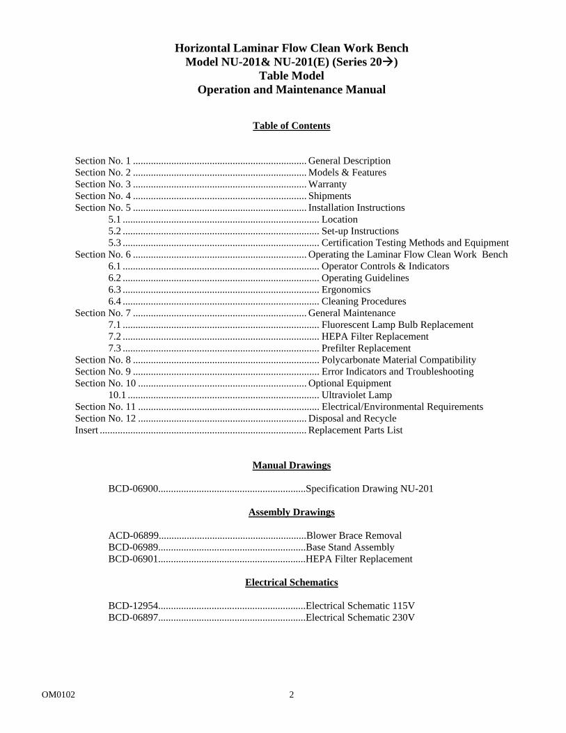
Table of Contents
Section No. 1 .................................................................... General Description Section No. 2 .................................................................... Models & Features Section No. 3 .................................................................... Warranty Section No. 4 .................................................................... Shipments Section No. 5 .................................................................... Installation Instructions
5.1 ............................................................................. Location 5.2 ............................................................................. Set-up Instructions 5.3 ............................................................................. Certification Testing Methods and Equipment
Section No. 6 .................................................................... Operating the Laminar Flow Clean Work Bench 6.1 ............................................................................. Operator Controls & Indicators 6.2 ............................................................................. Operating Guidelines 6.3 ............................................................................. Ergonomics 6.4 ............................................................................. Cleaning Procedures
Section No. 7 .................................................................... General Maintenance 7.1 ............................................................................. Fluorescent Lamp Bulb Replacement 7.2 ............................................................................. HEPA Filter Replacement 7.3 ............................................................................. Prefilter Replacement
Section No. 8 ......................................................................... Polycarbonate Material Compatibility Section No. 9 ......................................................................... Error Indicators and Troubleshooting Section No. 10 .................................................................. Optional Equipment
10.1 ........................................................................... Ultraviolet Lamp Section No. 11 ....................................................................... Electrical/Environmental Requirements Section No. 12 .................................................................. Disposal and Recycle Insert ................................................................................. Replacement Parts List
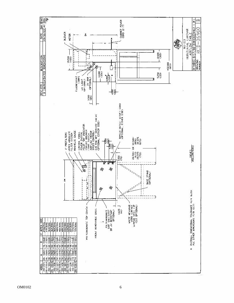
Manual Drawings BCD-06900..........................................................Specification Drawing NU-201
Assembly Drawings ACD-06899..........................................................Blower Brace Removal
BCD-06989..........................................................Base Stand Assembly BCD-06901..........................................................HEPA Filter Replacement
Electrical Schematics
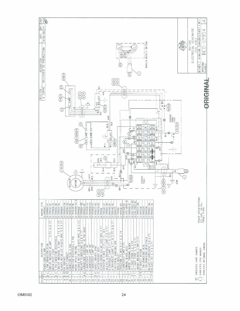
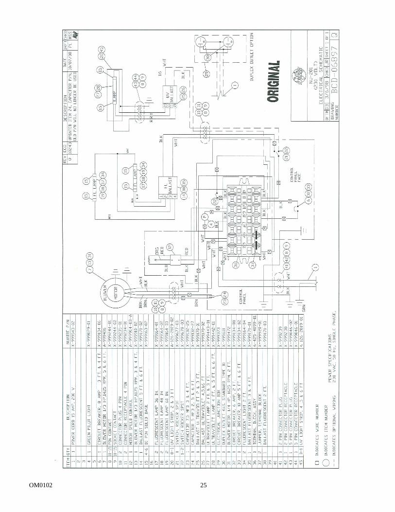
BCD-12954..........................................................Electrical Schematic 115V BCD-06897..........................................................Electrical Schematic 230V
OM0102 3
Horizontal Laminar Flow Clean Work Bench Models NU-201 & NU-201(E) (Series 20 )
Manufactured By: NuAire, Inc.,
Plymouth, Minnesota 1.0 General Description NuAire Horizontal Laminar Flow Clean Work Benches utilize the newest technologies in laminar airflow design, materials and manufacturing processes. The clean work bench can be used where clean airflow per Federal Standard 209c is required for the preparation of injectable drugs, IV solutions, tissue culture, optics, microelectronics, etc. The clean bench should not be used for any work that involves biological agents assigned a level of Risk 1 through 4 as classified by the Centers for Disease Control (CDC), Atlanta, Georgia, since the horizontal flow offers no personnel protection against these agents. The clean bench should only be used to protect the product from contamination. The clean bench is optionally available with a base stand, placing the work surface at 30” (762mm) or 36” (914mm). A significant number of design innovations give the NuAire Laminar flow equipment superior performance qualities in airflow, lighting, noise levels and vibration.
OM0102 4
1.1 Safety Instructions
These safety instructions describe the safety features of the Horizontal Laminar Flow Clean Work Bench model NU-201/E. The safety cabinet has been manufactured using the latest technological developments and has been thoroughly tested before delivery. It may, however, present potential hazards if it is not used according to the intended purpose or outside of operating parameters. Therefore, the following procedures must always be observed:
• The safety cabinet must be operated only by trained and authorized personnel. • For any operation of this unit, the operator must prepare clear and concise written instructions for
operating and cleaning, utilizing applicable safety data sheets, plant hygiene guidelines, and technical regulations, in particular.
o which decontamination measures are to be applied for the cabinet and accessories, o which protective measures apply while specific agents are used, o which measures are to be taken in the case of an accident.
• Repairs to the device must be carried out only by trained and authorized expert personnel. • Keep these operating instructions close to the unit so that safety instructions and important information
are always accessible. • Should you encounter problems that are not detailed adequately in the operating instructions, please
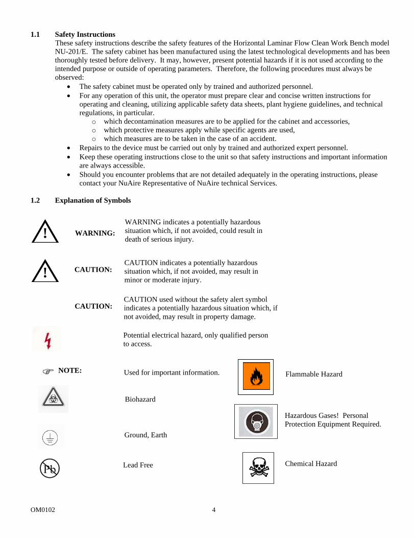
contact your NuAire Representative of NuAire technical Services. 1.2 Explanation of Symbols
!
!
NOTE:
WARNING indicates a potentially hazardous situation which, if not avoided, could result in death of serious injury.
CAUTION indicates a potentially hazardous situation which, if not avoided, may result in minor or moderate injury.
CAUTION used without the safety alert symbol indicates a potentially hazardous situation which, if not avoided, may result in property damage.
Potential electrical hazard, only qualified person to access.
Used for important information.
Biohazard
Ground, Earth
WARNING:
CAUTION:
CAUTION:
Lead Free Chemical Hazard
Flammable Hazard
Hazardous Gases! Personal Protection Equipment Required.
OM0102 5
2.0 Models and Features
NuAire's Model Number NU-201/E designates the basic design series of Horizontal Laminar Flow Clean Work Bench with the blower/motor located above the work surface (i.e. bench series). Model numbers are shown below.
Model Number NU-201-224 NU-201-230/(E) NU-201-324 NU-201-330/(E) NU-201-336 NU-201-424 NU-201-430/(E) NU-201-436 NU-201-524 NU-201-530/(E) NU-201-536 NU-201-624 NU-201-630/(E)
OM0102 6
OM0102 7
3.0 Warranty
NuAire, Inc. warrants that it will repair F.O.B. its factory or furnish without charge F.O.B. its factory a similar part to replace any material in its equipment within 36 months after the date of sale if proved to the satisfaction of the company to have been defective at the time it was sold provided that all parts claimed defective shall be returned, properly identified to the company at its factory, charges prepaid. Factory installed equipment or accessories are warranted only to the extent guaranteed by the original manufacturer, and this warranty shall not apply to any portion of the equipment modified by the user. Claims under this warranty should be directed to NuAire, Inc. setting forth in detail the nature of the defect, the date of the initial installation and the serial and model number of the equipment.
This warranty shall not apply to any NuAire product or part thereof, which has been subject to misuse, abuse, accident, shipping damage, improper installation or service, or damage by fire, flood or acts of God. If the serial number of this product is altered, removed or defaced as to be illegible, the warranty shall be null and void in its entirety.
The warranty is for the sole benefit of the original purchaser and is not assignable or transferable. Prior to returning any item, for any reason, contact NuAire, Inc. for a Return Authorization Number. This number must accompany all returns. Any product shipped to NuAire without this number will be returned, refused shipment or collect freight. 4.0 Shipments
NuAire takes every reasonable precaution to insure that your Labgard Cabinet arrives without damage. Motor carriers are carefully selected and shipping cartons have been specially designed to insure your purchase. However, damage can occur in any shipment and the following outlines the steps you should take on receipt of a NuAire Labgard Cabinet to be sure that if damage has occurred, the proper claims and actions are taken immediately. 4.1 Damaged Shipments
4.1.1 Terms are factory, unless stated otherwise. Therefore, it is important to check each shipment before acceptance.
4.1.2 If there is visible damage, the material can be accepted after the driver makes a notation on the
consignee's copy of the freight bill. Then an inspection must be made to verify the claim against the carrier. This inspection is the basis of your filing the claim against the carrier.
4.1.3 If concealed damage is found, it is absolutely necessary to NOTIFY THE FREIGHT AGENT AT ONCE
and request an inspection. Without this inspection, the transportation company may not accept a claim for loss or damage. If the carrier will not perform the inspection, an affidavit must be prepared stating that he was contacted on a certain date and that he failed to comply with the request. This, along with other papers in the customer's possession will support the claim.
OM0102 8
5.0 Installation Instructions 5.1 Location
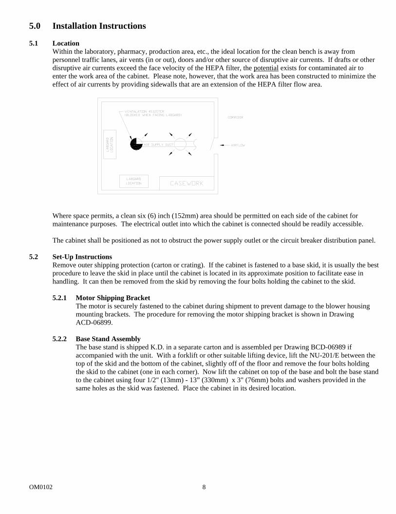
Within the laboratory, pharmacy, production area, etc., the ideal location for the clean bench is away from personnel traffic lanes, air vents (in or out), doors and/or other source of disruptive air currents. If drafts or other disruptive air currents exceed the face velocity of the HEPA filter, the potential exists for contaminated air to enter the work area of the cabinet. Please note, however, that the work area has been constructed to minimize the effect of air currents by providing sidewalls that are an extension of the HEPA filter flow area. Where space permits, a clean six (6) inch (152mm) area should be permitted on each side of the cabinet for maintenance purposes. The electrical outlet into which the cabinet is connected should be readily accessible. The cabinet shall be positioned as not to obstruct the power supply outlet or the circuit breaker distribution panel.
5.2 Set-Up Instructions
Remove outer shipping protection (carton or crating). If the cabinet is fastened to a base skid, it is usually the best procedure to leave the skid in place until the cabinet is located in its approximate position to facilitate ease in handling. It can then be removed from the skid by removing the four bolts holding the cabinet to the skid.
5.2.1 Motor Shipping Bracket
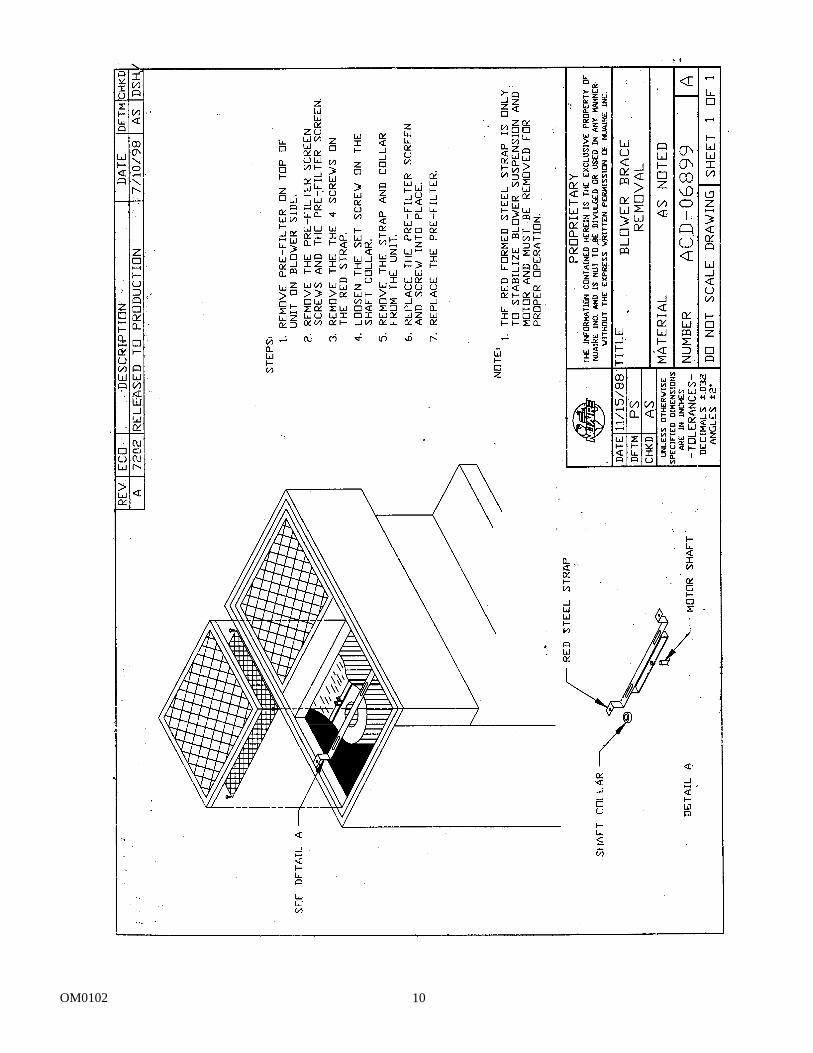
The motor is securely fastened to the cabinet during shipment to prevent damage to the blower housing mounting brackets. The procedure for removing the motor shipping bracket is shown in Drawing ACD-06899.
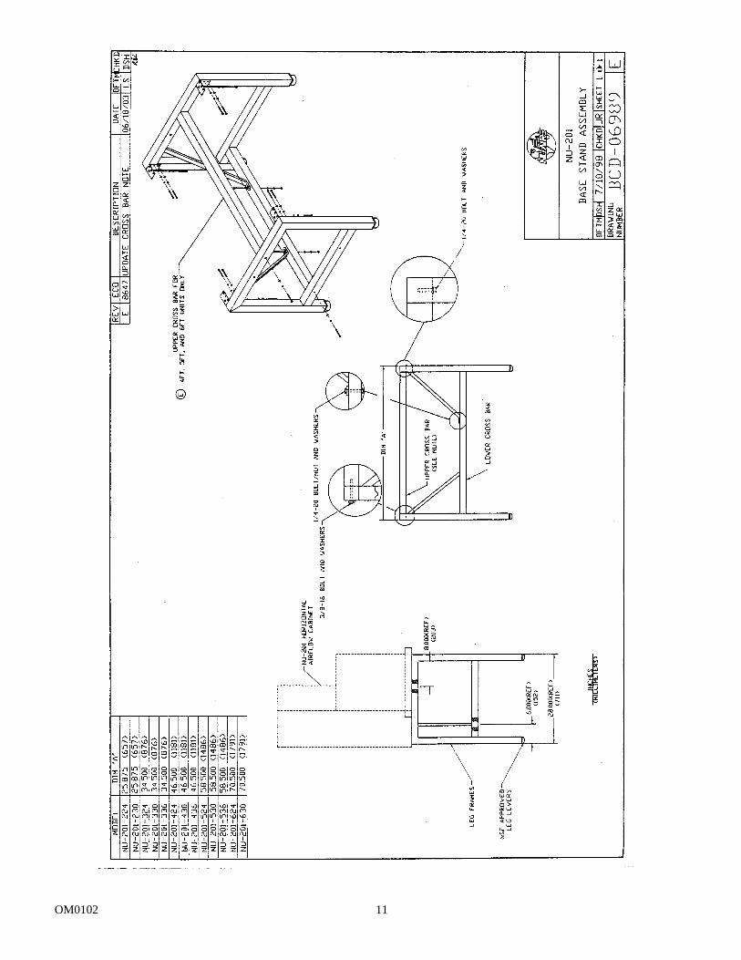
5.2.2 Base Stand Assembly
The base stand is shipped K.D. in a separate carton and is assembled per Drawing BCD-06989 if accompanied with the unit. With a forklift or other suitable lifting device, lift the NU-201/E between the top of the skid and the bottom of the cabinet, slightly off of the floor and remove the four bolts holding the skid to the cabinet (one in each corner). Now lift the cabinet on top of the base and bolt the base stand to the cabinet using four 1/2" (13mm) - 13” (330mm) x 3" (76mm) bolts and washers provided in the same holes as the skid was fastened. Place the cabinet in its desired location.
OM0102 9
CAUTION:
CAUTION:
5.2.3 Gas Service
NuAire doesn't recommend the use of natural gas within the clean bench, but if gas service is determined to be necessary for the application by the appropriate safety personnel, appropriate safety measures must take place.
Once the determination has been made by the appropriate safety personnel, the application of natural gas must be performed in accordance to national, state and local codes.
IT IS ALSO STRONGLY RECOMMENDED THAT AN EMERGENCY GAS SHUTOFF VALVE BE PLACED JUST OUTSIDE THE CLEAN BENCH ON THE GAS SUPPLY LINE.
All NuAire clean benches meet the safety requirements of UL and CSA for Laboratory Equipment. To comply with these safety requirements, NuAire uses only certified gas valves. In addition, if external piping is required, only black pipe is used for this application. As previously stated NuAire doesn't recommend the use of natural gas within the clean bench and ASSUMES NO RESPONSIBILITY FOR ITS USE. USE AT YOUR OWN RISK. The Bunsen burner flame within the clean bench disrupts the laminar air stream, which must be maintained for maximum efficiency.
IF THE PROCEDURE DEMANDS USE OF A FLAME, A BUNSEN BURNER WITH ON DEMAND IGNITION IS STRONGLY RECOMMENDED. DO NOT USE CONSTANT FLAME GAS BURNERS.
During use, the Bunsen burner should be placed to the rear of the workspace where resulting air turbulence will have a minimal effect.
5.2.4 Plumbing Services
Ground key cocks with the type of service specified by the snap-in button on the handle, are located in the work zone. The ground key cocks are not recommended for pressures over 30 p.s.i. Reducing valves should be installed external to the cabinet if necessary. Ground key cocks should never be used for oxygen service. A special needle valve for oxygen service is required and available upon request.
External connection is to 3/8 inch (10mm) FPT coupling through the sidewalls. Connection to plant utilities should be made with proper materials for the individual service and according to national and/or local codes. Observe all labels pertaining to the type of service and operating pressure.
!
!
OM0102 10
OM0102 11
OM0102 12
5.2.5 Electrical Services
The horizontal laminar flow work bench may be "hardwired" (optional) or connected via an electrical power cord, which is standard. The unit requires 115/230 VAC, 60/50 Hz, single phase. (Current rating varies per cabinet size, reference Electrical/Environmental Requirements). It is recommended that power to the unit be on its own branch circuit, protected with a 15 Amp circuit breaker or fuse at the distribution panel.
THIS UNIT CONTAINS ELECTRONIC BALLASTS FOR THE FLUORESCENT LIGHTING. ELECTRONIC BALLASTS OPERATE WITH HIGH INRUSH CURRENT. IT IS NOT RECOMMENDED TO USE THIS PRODUCT WITH GROUND FAULT CIRCUIT INTERRUPTERS (GFCI'S) BECAUSE THE BALLASTS MAY CAUSE THE GFCI TO TRIP.
If a "hardwired" (conduit) connection is desired, an electrical junction box is provided on the top of the cabinet with a removable cover. All wiring connections to the junction box should be done according to the National Electrical Code and/or local codes by a qualified electrician.
5.2.6 Final Assembly
The exterior surfaces and viewing glass are easily cleaned with any mild household detergent cleaner using a soft cloth. Harsh chemicals, solvent-type cleaners and abrasive cleaners should not be used.
Do not attempt to clean the HEPA filter media. Cabinet interior walls or work surface is easily cleaned with any mild household detergent cleaner using a soft cloth. Turn the cabinet on and let it operate for 60 minutes before using it as a clean bench.
5.3 Certification Testing Methods and Equipment
After installation and prior to use, NuAire recommends that the cabinet be recertified to factory standards. At a minimum, the following tests should be performed.
1. HEPA filter media 2. Filter frame leak test 3. Airflow velocities
The testing methods and equipment required are specified on the factory inspection report included with this manual (see insert in back cover).
IT IS RECOMMENDED THAT THESE TESTS BE PERFORMED BY A QUALIFIED TECHNICIAN WHO IS FAMILIAR WITH THE METHODS AND PROCEDURES FOR CERTIFYING CLEAN BENCHES.
AFTER THE INITIAL CERTIFICATION, NUAIRE RECOMMENDS THAT THE CABINET BE RECERTIFIED AT A MINIMUM ON AN ANNUAL BASIS AND AFTER EVERY FILTER CHANGE OR MAINTENANCE ACTION OR ANY TIME THE OPERATOR FEELS IT IS NECESSARY.
Note that the NuAire clean benches, filters and seals provide premium performance; Quality control in both design and manufacturing insure superior reliability. However, protection to the product is so important, that certification to the performance requirements should be accomplished as stated to insure conformance to factory standards.
NOTE:
NOTE:
NOTE:
OM0102 13
6.0 Operating the Laminar Flow Clean Bench 6.1 Operator Controls and Indicators
The following is a description of the controls and indicators provided on the NU-201 clean benches.
6.1.1 Fluorescent/UV Light Switch This switch provides on/off control for the fluorescent light and/or the ultraviolet (UV) light if present (optional). With the UV light option, the switch provides for on-center off-on operation so that both the fluorescent light and the UV light cannot be energized at the same time. Proper care should be exercised when the UV light is on.
6.1.2 Blower Switch
The blower switch applies power to the internal blower/motor when in the ON position.
6.1.3 Indicator Light - Blower A green neon indicator light is located next to the blower on/off switch and lights when power is applied to the motor/blower.
6.1.4 Circuit Breaker - Blower
The blower motor is protected with a circuit breaker. The circuit breaker, in conjunction with the motor's thermal protector, is designed to open under locked rotor or half-wave power conditions. Should the circuit breaker open, merely depress the button to reset. If the circuit breaker continually opens, a failure has occurred in the motor or solid-state speed controller. Consult a qualified repair technician or NuAire, Inc. for replacement.
6.1.5 Airflow Control
The operating horizontal airflow within the cabinet (i.e. 90 LFPM (.457 m/s) airflow) is controlled by a potentiometer. The potentiometer controls the operating voltage applied to the motor/blower. The potentiometer is adjustable over 270 degrees with a slotted screwdriver, which varies the applied voltage from 70 to 115 VAC or 120 to 230 VAC. This adjustment should only be made by a qualified technician employing the proper instruments in order to insure airflow.
6.1.6 Minihelic Gauge
The minihelic gauge displays the static pressure within the pressure plenum supplying air to the HEPA filter. The gauge is calibrated in "inches of water gauge" pressure. As the HEPA filter loads with particulate matter, the amount of static pressure will increase, giving an indication of the "health" of the cabinet. The initial pressure reading will be approximately 0.50" (13mm) w.g. + 0.05" (2mm) w.g depending on altitude from sea level. The cabinet should be checked for proper airflow at each 0.1-inch (2mm) increase in static pressure.
OM0102 14
6.2 Operating Guidelines Operate the laminar flow work bench continuously. The unit will then remain in its initially clean condition. If, for any reason, the unit is turned off, the face of the protective screen in horizontal airflow units should be cleaned - preferably with a small brush. Clean the interior surfaces with lukewarm water and a mild detergent. Turn the unit on and permit to operate for 15 minutes before resuming operations. Allow only essential items in the work station. Objects should not be placed between the HEPEX and any point where the clean environment must be maintained. New items introduced into the work area should be placed downstream of items already in the work zone for several minutes to allow contaminants to flush off. Note that plastic parts may carry a static charge which may require special handling in order to remove contaminants. Particular care must be exercised in placing equipment within the work space. Where possible, equipment should be placed on perforated platforms to allow air movement under as well as around the object. All work should be performed with the operator's hand or head downstream of the critical process points. Unnecessary movement with the work station should be kept to a minimum. If cabinet is used in a manner not specified by NuAire, the protection provided by the equipment may be impaired. 6.2.1 Operating Sequence
A. Start Up Turn on cabinet blower and lights, check air intake ports of the cabinet to make sure they are unobstructed. The cabinets are provided with gauges which indicate pressure differentials across the filters. They indicate when to replace the filters, dependent upon the blower fan capacity. Blower speed must only be readjusted by qualified maintenance technicians.
B. Some cabinets are equipped with ultraviolet (UV) lights. These must be turned off during the day while laboratory personnel are occupying the room. Good procedure includes the decontamination or wipedown of cabinet surfaces with chemical disinfectant before work commences. This practice eliminates the need for UV lights, whose primary utility in this application is inactivation of surface contamination since the filters effectively remove all airborne contaminants. UV lights, therefore, are not recommended.
C. Allow blowers to operate for a minimum of 5 minutes before aseptic manipulations are begun in the cabinet. An additional advantage is obtained from purification (filtration) of the room air circulated through the equipment. Because of the characteristic contributed to the quality of the laboratory environment, some owners leave them in operation beyond the time of actual use.
D. Minimize Room Activity - Activity in the room itself should be held to a minimum. Unnecessary
activity may create disruptive air currents, as well as interfere with the work of the operator. A person walking past the front of the cabinet can cause draft velocities up to 175 FPM, which are sufficient to disrupt the air balance of the Laminar Flow Unit.
E. Utilize Unidirectional Airflow - The operator must keep two important facts in mind: 1) The air,
as supplied to the work area through the HEPEX is contaminant-free. 2) Airborne contamination generated in the work area is controlled by the unidirectional flow of parallel air streams. A solid object placed in a laminar air stream will disrupt the parallel flow and consequently, the capability of controlling lateral movement of airborne particulates. A cone of turbulence extends behind the object and laminarity of the air stream is not regained until a point is reached downstream, approximately equal to three to six times the diameter of the object. Within the parameters of this cone, particles may be carried laterally by multidirectional eddy currents.
OM0102 15
CAUTION:
CAUTION:
6.3 Ergonomics Ergonomics, the study or accommodation of work practices is extremely important for proper cabinet usage and user health and safety. An evaluation of normal work practices should be performed with each user when working in a cabinet. Evaluation criteria should be at a minimum:
a. Proper user posture b. Effective workzone layout for work practice c. Vision or sightlines
For each of the above evaluation criterion, several aids may be supplied to accommodate the user. • Ergonomic chair - A six-way articulating seat and back control for personalized adjustment to assure proper
user posture. Be sure feet are resting on the floor, chair foot support or foot rest. Also be sure back is fully supported with proper chair adjustments.
• Forearm/elbow support - The cabinet is provided with a forearm support on the work access opening. Periodic mini-breaks during work practice should be taken resting forearm to avoid stress and fatigue. Elbow rests are optional that can provide support for particular work practices, such as pipetting.
• Effective workzone layout - Always prepare your work procedure to minimize reach to avoid neck and shoulder stress and fatigue. Rotating tables are optional to maximum workzone and minimize reach.
• Vision and sightline - Always prepare your work procedure to eliminate glare and bright reflections on the window. Keep your window clean and sightlines clear to your effect workzone.
6.4 Cleaning Procedures 6.4.1 To Clean Polycarbonate Side Panels
Use a damp soft cloth with a mild soap or mild inorganic acids/bases such as sodium-hydroxide, sodium-hypochlorite or mild bleaches or 3% peroxide.
DO NOT USE ORGANIC SOLVENTS, SUCH AS ALCOHOL, KETONES, ACETONE, TOTUOL, ETC., ON THE POLYCARBONATE - IT CAN CRAZE THE SURFACE UNDER CERTAIN CONDITIONS OF SURFACE STRESS AND HUMIDITY.
6.4.2 Recommendations for Cleaning Spills on the Work Surface
1. Discontinue work process if feasible and turn the blower motor off. 2. Inspect spill. 3. If contents of spill are potentially harmful, wear appropriate personnel protection equipment. 4. Remove debris from spill and wipe up liquids cautiously to prevent further contamination. 5. Broken containers and contaminated cleaning materials should be disposed of in appropriate disposal
containers (depends on type of contamination). 6. Wipe surfaces clean:
a. Apply appropriate disinfecting solution to clean bench surface. Most surface disinfectants require a specific contact time, depending upon the microbiological agents used within the cabinet. CONSULT APPROPRIATE DISINFECTANT DOCUMENTATION FOR PROPER APPLICATION AND SAFETY PRECAUTIONS.
DISINFECTANTS THAT USE CHLORIDES AND HALOGENS WILL CAUSE DAMAGE TO THE STAINLESS STEEL SURFACES IF LEFT ON FOR LONG PERIODS OF TIME.
b. After the specified contact time, wipe up excess disinfectant. IF THE
DISINFECTANT USED CONTAINS CHLORIDES OR HALOGENS, RE-WIPE ALL SURFACES WITH 70% AHCOHOL OR SIMILAR NON-CORROSIVE ANTI-MICROBIL AGENT TO PREVENT DAMAGE TO STAINLESS STEEL SUFACES
7. Leave the unit running for 5 to 30 minutes before continuing work to allow the system to purge itself.
OM0102 16
7.0 General Maintenance
CAUTION: All maintenance actions on this equipment must be performed by a qualified technician who is familiar with the proper maintenance procedures required for this equipment. This includes both certification as well as repair.
7.1 Fluorescent Lamp Bulb Replacement
The fluorescent bulbs are T8, cool white, electronic start and obscured from direct view by Plexiglas diffuser. The life rating of a bulb is 9000 hours based on three hour burning cycles.
To replace a bulb:
1. First, switch the cabinet light switch off. 2. Second, remove the front cover. Two knurled thumbscrews on either side of the front panel light cover.
And either one (for 3 or 4 ft. units) or two (for 5 to 6 ft. units) knurled thumbscrews below the front cover through the Plexiglas top panel. Once removed, the bulbs are directly exposed.
3. The lamp bulbs are removed by rotating until the pins can be pulled down. 4. Reverse the procedure to reinstall the lamp assembly.
7.2 HEPA Filter Replacement
The HEPA filter, under normal usage and barring an accident (puncture), does not need replacement until the efflux velocity cannot be maintained at 90 LFPM (.457 m/s) + 10%. This may permit the HEPA filter efflux average to be as low as 81 LFPM (.411 m/s), as long as no point falls below 70 LFPM (.355 m/s). Use only replacement filters of the same rated flow and size as originally installed to insure proper airflow and HEPA filter lifetime can be achieved.
The HEPEX system is removed as follows (see also the procedures on Drawing BCD-06901):
1. Remove the prefilters. 2. Remove the prefilter screen by unscrewing 4 screws per screen. 3. Remove the front cover. Remove the 2 screws on either side of the front panel light cover. Two knurled
thumbscrews 8 in. (203mm) down inside the top of the front cover and either one (3 or 4 foot units) or two (5 to 6 foot units) knurled thumbscrews below the front cover through the Plexiglas top panel.
4. Remove Clamping Strap holding HEPEX plastic plenum to Blower. 5. Remove the HEPA filter protective screen. 6. Remove the diffuser lip. 7. Remove the HEPEX filter by tipping the top forward -- then lifting completely out.
NOTE: This step usually requires 2 people for the removal and replacement of the HEPEX.
8. Replace new HEPEX by proceeding through the disassembly steps backwards. 9. For complete confidence that the Clean Work Bench is providing the bio-clean environment desired --
the bench should be checked for filter integrity and airflow by a competent technician. Airflow velocity should be regulated to an average 90 FPM (.457 m/s) (via the solid state motor speed control on the blower (16); Cleanliness should meet Federal Standard 209c, Class 10 conditions.
7.3 Pre-Filter Replacement
The replacement interval depends on the contaminant (large particles or lint) in the room -- a typical period is every 3 months. The prefilters are located on the top of the cabinet.
OM0102 17
OM0102 18
8.0 Polycarbonate Material Compatibility 8.1 Polycarbonate sheet is resistant at 70° to these chemicals. Amyl alcohol Chromic acid (20%) Lactic acid (20%) Potassium bromate Sodium chloride Aluminum chloride Citric acid (40%) Magnesium chloride Potassium bromide Sodium hypochlorite Aluminum sulphate Copper chloride Magnesium sulphate Potassium nitrate Sodium sulphate Ammonium chloride Copper sulphate Maganese sulphate Potassium perchlorate Stannous chloride Ammonium nitrate Formic acid (10%) Mercuric chloride Potassium permanganate Sulfur Ammonium sulphate Formalin (30%) Nickel sulphate Potassium persulphate Sulfuric acid (>10%) Antimony trichloride Glycerine Nitric acid (10%) Potassium sulphate Sulfuric acid (50%) Arsenic acid Heptane Nitric acid (20%) Silicone oil Tartaric acid (30%) Butyl alcohol Hydrochloric acid (10%) Oleic acid Silver nitrate Zinc chloride Calcium nitrate Hydrogen peroxide (30%) Oxalic acid Sodium bicarbonate Zinc sulphate Chlorinated Lime Paste Hydrofluoric acid (10%) Pentane Sodium bisulphate Chrome alum Isopropyl alcohol (70%) Phosphoric acid (10%) Sodium carbonate 8.2 Polycarbonate sheet is not resistant to these chemicals. Acetaldehyde Carbon tetrachloride Ethane tetrachloride Phenol Acetic acid (conc.) Carbon disulfide Ethylamine Phosphorous hydroxy chloride Acetone Carbolic acid Ethylene dichloride Phosphorous trichloride Acrylonitrile Caustic potash solution (5%) Ethyl ether Proplonic acid Ammonia Caustic soda solution (5%) Ethylene chlorohydrin Pyridine Ammonium fluoride Chloroform Formic acid (conc.) Sodium sulfide Ammonium hydroxide Chlorothene Freon (refrigerant & propellant) Sodium hydroxide Ammonium sulfide Chlorobenzene Gasoline Sodium nitrate Benzene Cresol Lacquer thinner Sylfuric acid (1%) Benzoic acid Cutting oils Methyl alcohol Tetrahydronaphthalene Benzyl alcohol Cyclo hexanone Methylene chloride Thiophene Brake fluid Cyclohexene Nitrobezene Toluene Bromobenzene Dimethyl formamide Nurocellulose lacquer Turpentine Butylic acid Dioxane Ozone Xylene
OM0102 19
9.0 Error Indicators & Troubleshooting
Audible alarms and error indicators occur for a variety of reasons. Whenever an alarm condition is present, the audible alarm and error indicator will be presented and stay on until the error is cleared. When presented with an error indicator, please perform the following:
Step 1: NOTE ALL ERROR INDICATORS. When the cabinet is running, any and all red indicators display an error.
Step 2: VERIFY ERROR INDICATORS. Error indicators can be verified by turning the error function on/off.
Step 3: MONITOR RE-OCCURRENCE OF ERROR INDICATORS. If re-occurrence of the error indicator is
immediate or daily, use guide below to correct the situation.
Error Indicator Troubleshooting Guide
Error Indicator Indicator Correction Clean bench fluorescent lights won't turn on.
Check blower/light circuit breaker on top of control center. Check fluorescent lamps. Check voltage to light ballasts. Check ballast. Check light switch.
Clean bench blower won't turn on. Check blower/light circuit breaker
on control center. Check voltage to blower. Check wiring to blower. Check blower capacitor. Check blower motor. (Note: blower motor has internal thermal protector. Let blower motor cool off for a minimum of 30 minutes to assure thermal protector is not open.)
Clean bench ultraviolet light won't turn on.
Check blower/light circuit breaker on top of control center. Check ultraviolet lamp. Check voltage to ultraviolet ballasts. Check ballast. Check light switch.
Blower/lights circuit breaker continues to trip after reset.
Check for short on output of circuit breaker. Replace circuit breaker. Isolate output of circuit breaker by disconnecting control center connectors, light circuit, motor voltage regulator, etc. to isolate the short.
Minihelic gauge Minihelic gauge
reads "NO" or "LOW FLOW"
Check minihelic gauge operation. Check for pinched tubing in control center. Make sure airflow is not too low.
OM0102 20
10.0 Optional Equipment 10.1 Ultraviolet Lamp 10.1.1 Overview
The germicidal ultraviolet is primarily intended for the destruction of bacteria and other micro-organisms in the air or on directly exposed surfaces. Approximately 95% of the ultraviolet radiations from germicidal tubes are in the 253.7 nanometer region. This is the region in the ultraviolet spectrum which is near the peak of germicidal effectiveness. The exposure necessary to kill bacteria is the product of time and intensity. High intensities for a short period of time, or low intensities for a longer period are fundamentally equal in lethal dosage on bacteria (disregarding the life cycle of bacteria). The intensity of light falling on a given area is governed by the inverse law; that is the killing intensity decreases as the distance increases from the tube.
The germicidal tube is placed in the cabinet to provide an average intensity of 100 microwatts per centimeter (for a new tube) falling on the horizontal plane defined by the bottom of the work surface. The minimum requirement per paragraph 5.12 of NSF Standard 49 to 40 microwatts per square centimeter.
The UV light on/off switch is located in the Service Control Center and is wired with the fluorescent light switch so that the UV light cannot be used when the fluorescent light is on.
10.1.2 Precaution
The rays from germicidal tubes may cause a painful, but temporary irritation of the eyes and reddening of the skin if of sufficiently high intensity, or if exposure covers a prolonged period of time. For this reason, one should avoid direct eye and skin exposure to ultraviolet light. If exposure cannot be avoided, it is necessary for personnel to wear eye goggles or face shields, and long sleeve gowns with rubber gloves.
10.1.3 Maintenance
The output of an ultraviolet lamp deteriorates with burning age. The useful life of the lamp is approximately 7000 hrs under specific test conditions. If the tube is turned on every day for 12 hours, the tube will last approximately two years.
It is recommended that either a time schedule be established or the tube's output be measured periodically and the tube replaced when its output falls below 40 microwatts per square centimeter or exceeds 7000 hours of operation. Lamps should be allowed to operate approximately 5 to 10 minutes (longer when the lamp is in low temperatures) to warm up sufficiently and wiped clean of dust or dirt before reading the output with a meter. Even minute amounts of dust will absorb ultraviolet energy.
The lamp may be cleaned with a lint-free cloth dampened with alcohol or ammonia and water.
OM0102 21
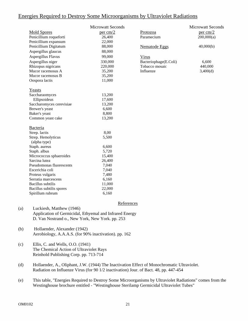
Energies Required to Destroy Some Microorganisms by Ultraviolet Radiations
Mold Spores
Microwatt Seconds per cm/2
Protozoa
Microwatt Seconds per cm/2
Penicillium roqueforti 26,400 Paramecium 200,000(a) Penicillium expansum 22,000 Penicillium Digitatum 88,000 Nematode Eggs 40,000(b) Aspergillus glaucus 88,000 Aspergillus Flavus 99,000 Virus Aspergillus niger 330,000 Bacteriophage(E.Coli) 6,600 Rhizopus nigricans 220,000 Tobacco mosaic 440,000 Mucor racemosus A 35,200 Influenze 3,400(d) Mucor racemosus B 35,200 Oospora lactis 11,000 Yeasts Saccharaomyces Ellipsoideus
13,200 17,600
Saccharomyces cerevisiae 13,200 Brewer's yeast 6,600 Baker's yeast 8,800 Common yeast cake 13,200 Bacteria Strep. lactis 8,00 Strep. Hemolyticus (alpha type)
5,500
Staph. aureus 6,600 Staph. albus 5,720 Micrococcus sphaeroides 15,400 Sarcina lutea 26,400 Pseudomonas fluorescents 7,040 Escerichia coli 7,040 Proteus vulgaris 7,480 Serratia marcescens 6,160 Bacillus subtilis 11,000 Bacillus subtilis spores 22,000 Spirillum rubrum 6,160
References
(a) Luckiesh, Matthew (1946) Application of Germicidal, Ethyemal and Infrared Energy D. Van Nostrand o., New York, New York. pp. 253 (b) Hollaender, Alexander (1942) Aerobiology, A.A.A.S. (for 90% inactivation). pp. 162 (c) Ellis, C. and Wells, O.O. (1941) The Chemical Action of Ultraviolet Rays Reinhold Publishing Corp. pp. 713-714 (d) Hollaender, A., Oliphant, J.W. (1944) The Inactivation Effect of Monochromatic Ultraviolet. Radiation on Influenze Virus (for 90 1/2 inactivation) Jour. of Bact. 48, pp. 447-454 (e) This table, "Energies Required to Destroy Some Microorganisms by Ultraviolet Radiations" comes from the Westinghouse brochure entitled - "Westinghouse Sterilamp Germicidal Ultraviolet Tubes"
OM0102 22
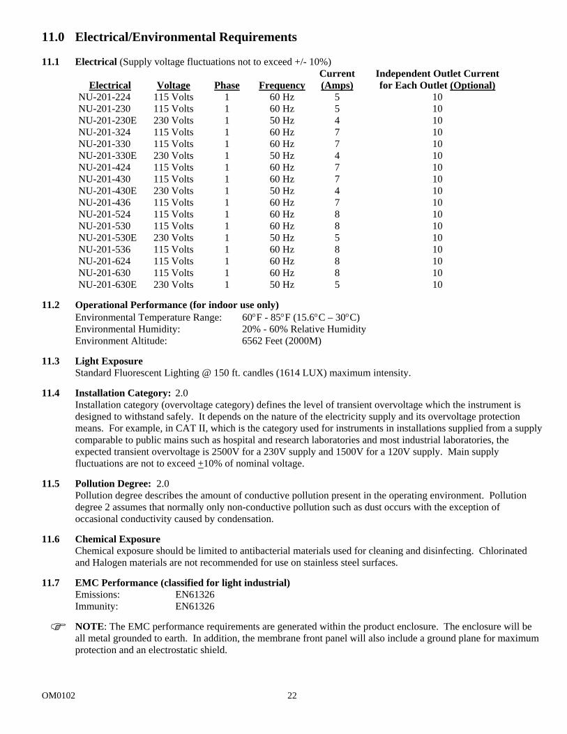
11.0 Electrical/Environmental Requirements 11.1 Electrical (Supply voltage fluctuations not to exceed +/- 10%)
Electrical
Voltage
Phase
Frequency
Current (Amps)
Independent Outlet Current for Each Outlet (Optional)
NU-201-224 115 Volts 1 60 Hz 5 10 NU-201-230 115 Volts 1 60 Hz 5 10 NU-201-230E 230 Volts 1 50 Hz 4 10 NU-201-324 115 Volts 1 60 Hz 7 10 NU-201-330 115 Volts 1 60 Hz 7 10 NU-201-330E 230 Volts 1 50 Hz 4 10 NU-201-424 115 Volts 1 60 Hz 7 10 NU-201-430 115 Volts 1 60 Hz 7 10 NU-201-430E 230 Volts 1 50 Hz 4 10 NU-201-436 115 Volts 1 60 Hz 7 10 NU-201-524 115 Volts 1 60 Hz 8 10 NU-201-530 115 Volts 1 60 Hz 8 10 NU-201-530E 230 Volts 1 50 Hz 5 10 NU-201-536 115 Volts 1 60 Hz 8 10 NU-201-624 115 Volts 1 60 Hz 8 10 NU-201-630 115 Volts 1 60 Hz 8 10 NU-201-630E 230 Volts 1 50 Hz 5 10
11.2 Operational Performance (for indoor use only)
Environmental Temperature Range: 60°F - 85°F (15.6°C – 30°C) Environmental Humidity: 20% - 60% Relative Humidity Environment Altitude: 6562 Feet (2000M)
11.3 Light Exposure
Standard Fluorescent Lighting @ 150 ft. candles (1614 LUX) maximum intensity. 11.4 Installation Category: 2.0
Installation category (overvoltage category) defines the level of transient overvoltage which the instrument is designed to withstand safely. It depends on the nature of the electricity supply and its overvoltage protection means. For example, in CAT II, which is the category used for instruments in installations supplied from a supply comparable to public mains such as hospital and research laboratories and most industrial laboratories, the expected transient overvoltage is 2500V for a 230V supply and 1500V for a 120V supply. Main supply fluctuations are not to exceed +10% of nominal voltage.
11.5 Pollution Degree: 2.0
Pollution degree describes the amount of conductive pollution present in the operating environment. Pollution degree 2 assumes that normally only non-conductive pollution such as dust occurs with the exception of occasional conductivity caused by condensation.
11.6 Chemical Exposure
Chemical exposure should be limited to antibacterial materials used for cleaning and disinfecting. Chlorinated and Halogen materials are not recommended for use on stainless steel surfaces.
11.7 EMC Performance (classified for light industrial)
Emissions: EN61326 Immunity: EN61326 NOTE: The EMC performance requirements are generated within the product enclosure. The enclosure will be all metal grounded to earth. In addition, the membrane front panel will also include a ground plane for maximum protection and an electrostatic shield.
OM0102 23
CAUTION
NOTE:
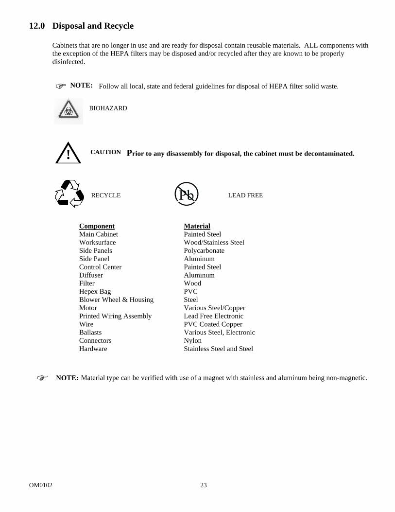
12.0 Disposal and Recycle
Cabinets that are no longer in use and are ready for disposal contain reusable materials. ALL components with the exception of the HEPA filters may be disposed and/or recycled after they are known to be properly disinfected. Follow all local, state and federal guidelines for disposal of HEPA filter solid waste.
Prior to any disassembly for disposal, the cabinet must be decontaminated.
Component Material Main Cabinet Painted Steel Worksurface Wood/Stainless Steel Side Panels Polycarbonate Side Panel Aluminum Control Center Painted Steel Diffuser Aluminum Filter Wood Hepex Bag PVC Blower Wheel & Housing Steel Motor Various Steel/Copper Printed Wiring Assembly Lead Free Electronic Wire PVC Coated Copper Ballasts Various Steel, Electronic Connectors Nylon Hardware Stainless Steel and Steel
Material type can be verified with use of a magnet with stainless and aluminum being non-magnetic.
NOTE:
!
BIOHAZARD
RECYCLE
LEAD FREE
OM0102 24
OM0102 25