Horizontal Float Switch Installation, Operation...
16
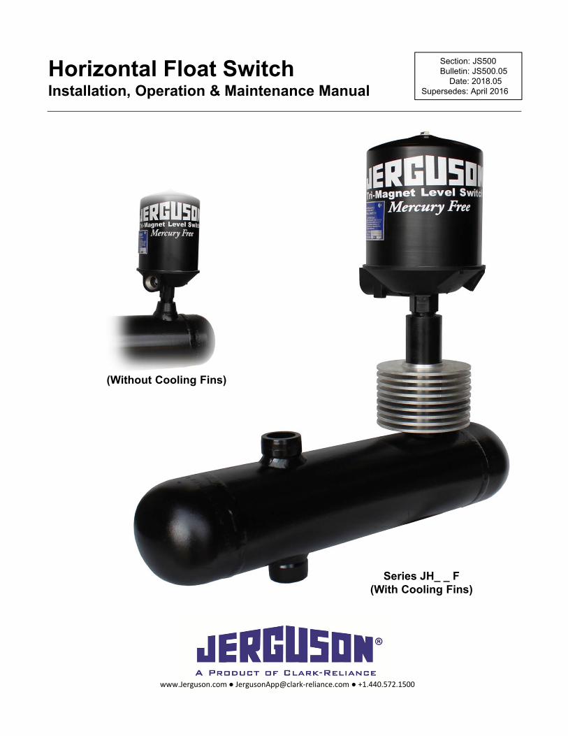
Installation, Operation, & Maintenance Instructions IOM JS500.05 2018.05 Horizontal Float Switches Horizontal Float Switch Installation, Operation & Maintenance Manual Section: JS500 Bulletin: JS500.05 Date: 2018.05 Supersedes: April 2016 www.Jerguson.com ● [email protected] ● +1.440.572.1500 Series JH_ _ F (With Cooling Fins) (Without Cooling Fins)
Transcript of Horizontal Float Switch Installation, Operation...
Installation, Operation, & Maintenance InstructionsIOM JS500.05
2018.05Horizontal Float Switches Horizontal Float SwitchInstallation, Operation & Maintenance Manual
Section: JS500Bulletin: JS500.05
Date: 2018.05Supersedes: April 2016
www.Jerguson.com ● [email protected] ● +1.440.572.1500
Series JH_ _ F(With Cooling Fins)
(Without Cooling Fins)
Installation, Operation, & Maintenance InstructionsIOM JS500.05
2018.05Horizontal Float Switches
Table of Contents
Principle of Operation 3Switch Assembly Identification 3Model Number – Part 1: Switch Assembly 4Model Number – Part 2: Spare Enclosure & Pressure Tube 5Electrical Characteristics, Wiring Examples, & Switch Ratings 6Switch Mechanisms – Simple Apparatus 7Installation – Part 1: Switch Assembly 8Installation – Part 2: Spare Enclosure & Pressure Tube 9Installation Specific to Hazardous Area 10Putting the Switch into Service 11Taking the Switch out of Service 11Maintenance 11Dimensional Data 12Bolting: Torque Values & Tightening Sequence 13Switching Point Adjustment 14Switch Mechanism Replacement 14Spare/Replacement Parts 14Tag Information 15Parts Store 16
www.Jerguson.com ● [email protected] ● +1.440.572.1500
2
Installation, Operation, & Maintenance InstructionsIOM JS500.05
2018.05Horizontal Float Switches
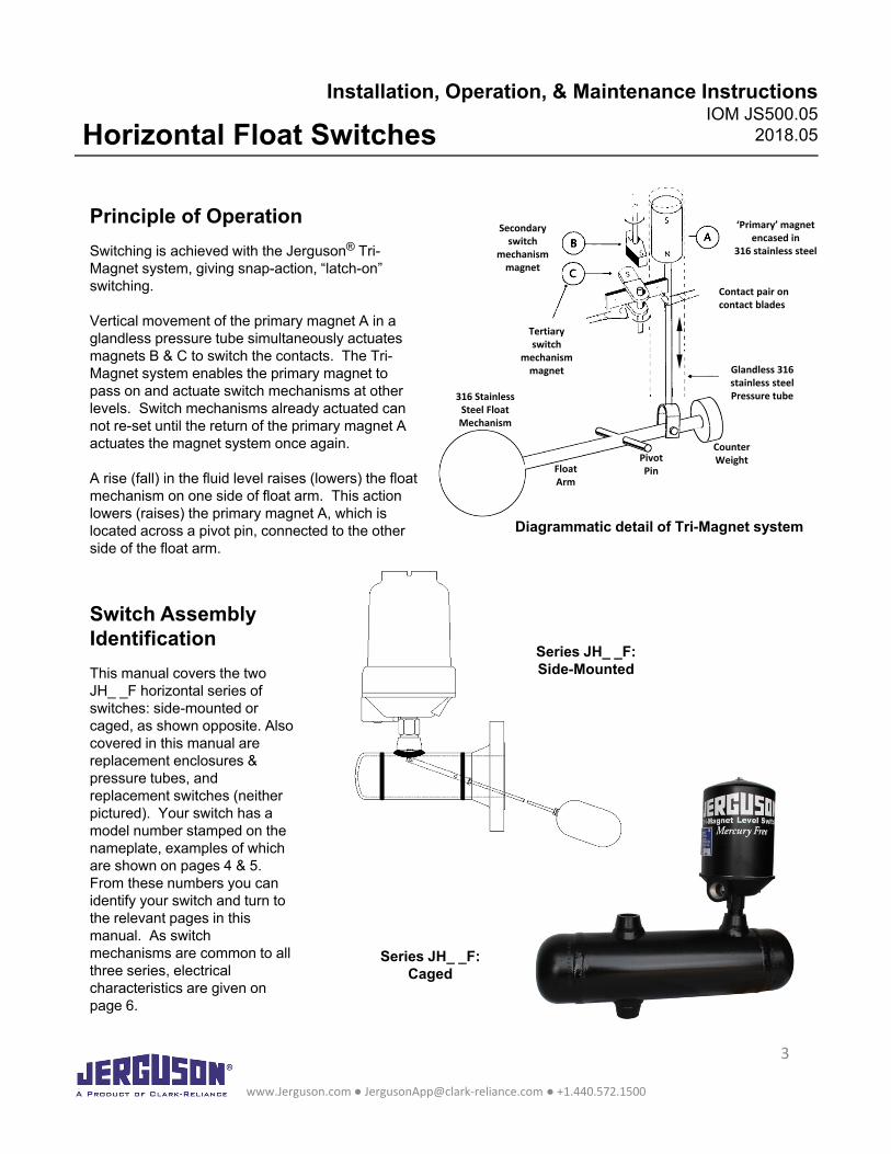
Principle of Operation
Switching is achieved with the Jerguson® Tri-Magnet system, giving snap-action, “latch-on” switching.
Vertical movement of the primary magnet A in a glandless pressure tube simultaneously actuates magnets B & C to switch the contacts. The Tri-Magnet system enables the primary magnet to pass on and actuate switch mechanisms at other levels. Switch mechanisms already actuated can not re-set until the return of the primary magnet A actuates the magnet system once again.
A rise (fall) in the fluid level raises (lowers) the float mechanism on one side of float arm. This action lowers (raises) the primary magnet A, which is located across a pivot pin, connected to the other side of the float arm.
Diagrammatic detail of Tri-Magnet system
Series JH_ _F:Side-Mounted
Series JH_ _F:Caged
Switch Assembly Identification
This manual covers the two JH_ _F horizontal series of switches: side-mounted or caged, as shown opposite. Also covered in this manual are replacement enclosures & pressure tubes, and replacement switches (neither pictured). Your switch has a model number stamped on the nameplate, examples of which are shown on pages 4 & 5. From these numbers you can identify your switch and turn to the relevant pages in this manual. As switch mechanisms are common to all three series, electrical characteristics are given on page 6.
www.Jerguson.com ● [email protected] ● +1.440.572.1500
3
Secondaryswitch
mechanismmagnet
Tertiaryswitch
mechanismmagnet
Contact pair oncontact blades
‘Primary’ magnetencased in
316 stainless steel
316 StainlessSteel Float Mechanism
Glandless 316 stainless steelPressure tube
FloatArm
PivotPin
CounterWeight
Installation, Operation, & Maintenance InstructionsIOM JS500.05
2018.05Horizontal Float Switches
1 Standard offerings listed, but alternates are allowed. Unlisted alternates do not affect hazardous area safety components
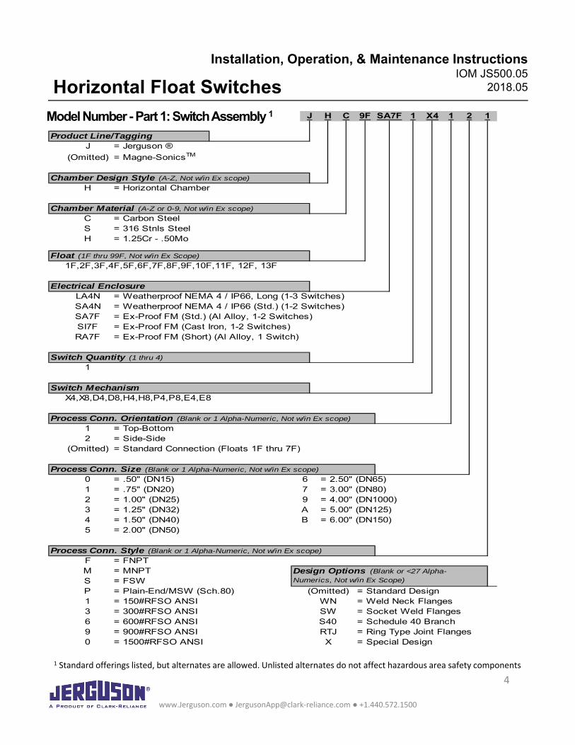
Model Number -Part 1: Switch Assembly 1
www.Jerguson.com ● [email protected] ● +1.440.572.1500
4
Product Line/TaggingJ = Jerguson ®
(Omitted) = Magne-SonicsTM
H = Horizontal Chamber
C = Carbon SteelS = 316 Stnls SteelH = 1.25Cr - .50Mo
1F,2F,3F,4F,5F,6F,7F,8F,9F,10F,11F, 12F, 13F
LA4N = Weatherproof NEMA 4 / IP66, Long (1-3 Switches)SA4N = Weatherproof NEMA 4 / IP66 (Std.) (1-2 Switches)SA7F = Ex-Proof FM (Std.) (Al Alloy, 1-2 Switches)SI7F = Ex-Proof FM (Cast Iron, 1-2 Switches)RA7F = Ex-Proof FM (Short) (Al Alloy, 1 Switch)
1
X4,X8,D4,D8,H4,H8,P4,P8,E4,E8
1 = Top-Bottom2 = Side-Side
(Omitted) = Standard Connection (Floats 1F thru 7F)
0 = .50" (DN15)1 = .75" (DN20)2 = 1.00" (DN25) = 4.00" (DN1000)3 = 1.25" (DN32) = 5.00" (DN125)4 = 1.50" (DN40) = 6.00" (DN150)5 = 2.00" (DN50)
F = FNPTM = MNPTS = FSWP = Plain-End/MSW (Sch.80)1 = 150#RFSO ANSI3 = 300#RFSO ANSI6 = 600#RFSO ANSI9 = 900#RFSO ANSI0 = 1500#RFSO ANSI
1 2 1
6 = 2.50" (DN65)
Process Conn. Orientation (Blank or 1 Alpha-Numeric, Not w/in Ex scope)
J H C
9AB
X49F SA7F 1
Process Conn. Size (Blank or 1 Alpha-Numeric, Not w/in Ex scope)
(Omitted) = Standard DesignWN = Weld Neck FlangesSW = Socket Weld FlangesS40 = Schedule 40 BranchRTJ = Ring Type Joint FlangesX = Special Design
Process Conn. Style (Blank or 1 Alpha-Numeric, Not w/in Ex scope)
Design Options (Blank or <27 Alpha-Numerics, Not w/in Ex Scope)
Chamber Design Style (A-Z, Not w/in Ex scope)
Chamber Material (A-Z or 0-9, Not w/in Ex scope)
Float (1F thru 99F, Not w/in Ex Scope)
Electrical Enclosure
Switch Quantity (1 thru 4)
Switch Mechanism
7 = 3.00" (DN80)
Installation, Operation, & Maintenance InstructionsIOM JS500.05
2018.05Horizontal Float Switches
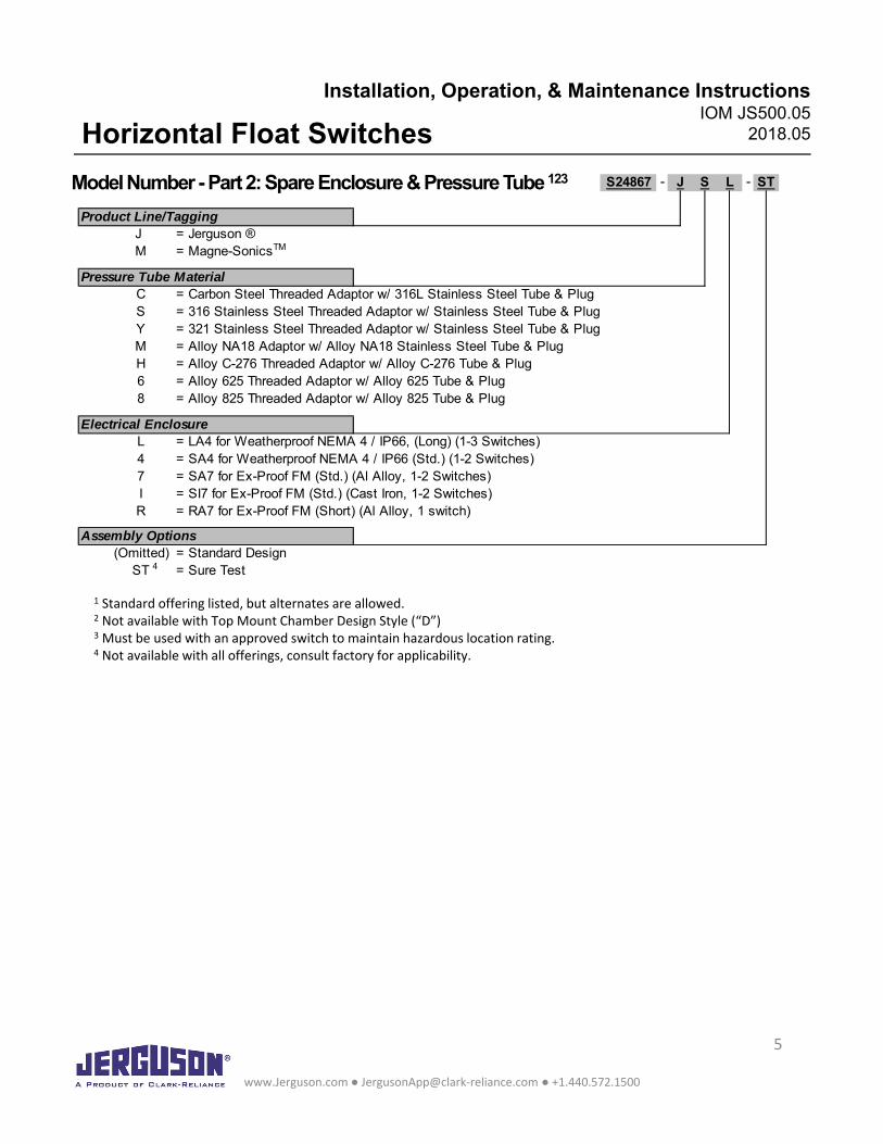
Model Number -Part 2: Spare Enclosure & Pressure Tube 123
www.Jerguson.com ● [email protected] ● +1.440.572.1500
5
1 Standard offering listed, but alternates are allowed.2 Not available with Top Mount Chamber Design Style (“D”)3 Must be used with an approved switch to maintain hazardous location rating.4 Not available with all offerings, consult factory for applicability.
S24867 - -
Product Line/TaggingJ = Jerguson ®M = Magne-SonicsTM
Pressure Tube MaterialC = Carbon Steel Threaded Adaptor w/ 316L Stainless Steel Tube & PlugS = 316 Stainless Steel Threaded Adaptor w/ Stainless Steel Tube & PlugY = 321 Stainless Steel Threaded Adaptor w/ Stainless Steel Tube & PlugM = Alloy NA18 Adaptor w/ Alloy NA18 Stainless Steel Tube & PlugH = Alloy C-276 Threaded Adaptor w/ Alloy C-276 Tube & Plug6 = Alloy 625 Threaded Adaptor w/ Alloy 625 Tube & Plug8 = Alloy 825 Threaded Adaptor w/ Alloy 825 Tube & Plug
Electrical EnclosureL = LA4 for Weatherproof NEMA 4 / IP66, (Long) (1-3 Switches)4 = SA4 for Weatherproof NEMA 4 / IP66 (Std.) (1-2 Switches)7 = SA7 for Ex-Proof FM (Std.) (Al Alloy, 1-2 Switches)I = SI7 for Ex-Proof FM (Std.) (Cast Iron, 1-2 Switches)R = RA7 for Ex-Proof FM (Short) (Al Alloy, 1 switch)
Assembly Options(Omitted) = Standard Design
ST 4 = Sure Test
STJ S L
Installation, Operation, & Maintenance InstructionsIOM JS500.05
2018.05Horizontal Float Switches
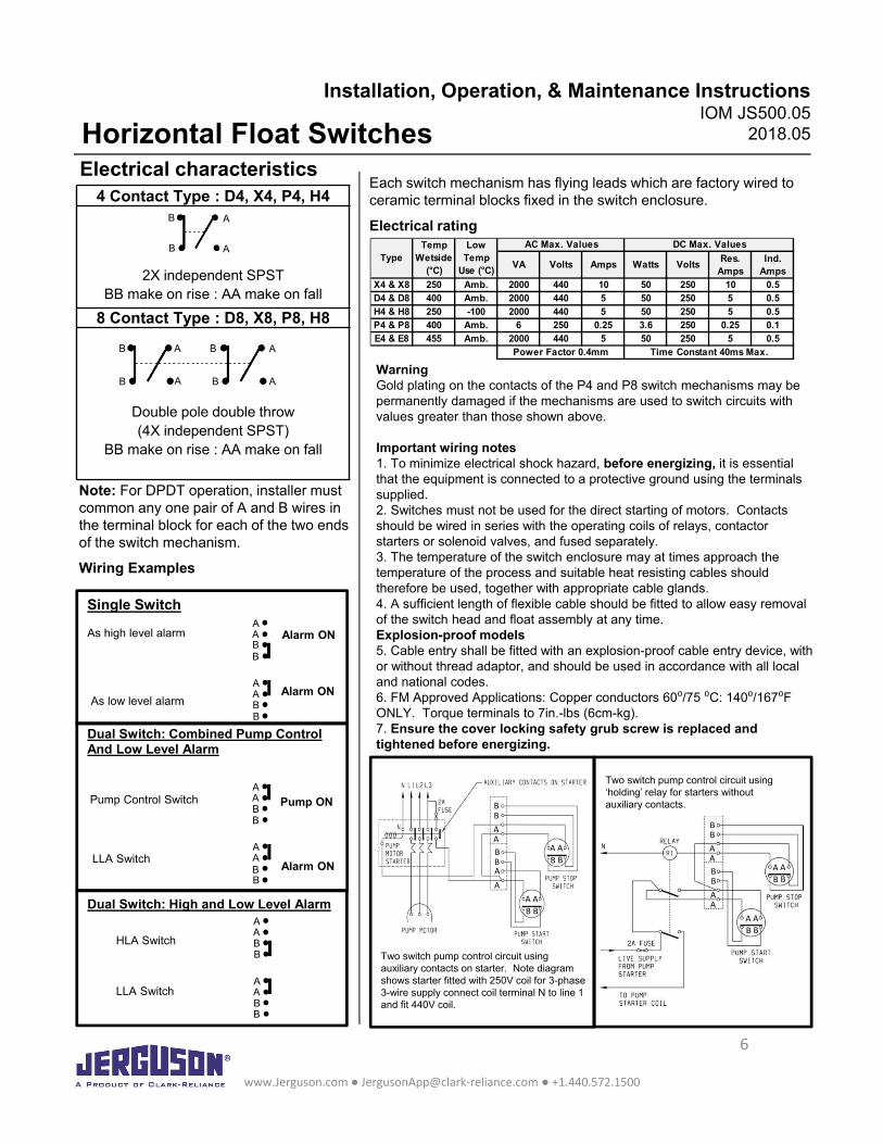
VA Volts Amps Watts VoltsRes.
AmpsInd.
AmpsX4 & X8 250 Amb. 2000 440 10 50 250 10 0.5D4 & D8 400 Amb. 2000 440 5 50 250 5 0.5H4 & H8 250 -100 2000 440 5 50 250 5 0.5P4 & P8 400 Amb. 6 250 0.25 3.6 250 0.25 0.1E4 & E8 455 Amb. 2000 440 5 50 250 5 0.5
AC Max. Values DC Max. ValuesTemp Wetside
(°C)
Low Temp
Use (°C)Type
Power Factor 0.4mm Time Constant 40ms Max.
Electrical characteristics4 Contact Type : D4, X4, P4, H4
2X independent SPSTBB make on rise : AA make on fall
8 Contact Type : D8, X8, P8, H8
Double pole double throw(4X independent SPST)
BB make on rise : AA make on fall
Note: For DPDT operation, installer must common any one pair of A and B wires in the terminal block for each of the two ends of the switch mechanism.
Wiring Examples
Single Switch
As high level alarm
As low level alarm
Pump Control Switch
LLA Switch
AABB
AABB
Alarm ON
Alarm ON
Dual Switch: Combined Pump ControlAnd Low Level Alarm
AABB
AABB
Pump ON
Alarm ON
Dual Switch: High and Low Level AlarmAABB
AABB
HLA Switch
LLA Switch
Each switch mechanism has flying leads which are factory wired to ceramic terminal blocks fixed in the switch enclosure.
Electrical rating
WarningGold plating on the contacts of the P4 and P8 switch mechanisms may be permanently damaged if the mechanisms are used to switch circuits with values greater than those shown above.
Important wiring notes1. To minimize electrical shock hazard, before energizing, it is essential that the equipment is connected to a protective ground using the terminals supplied.2. Switches must not be used for the direct starting of motors. Contacts should be wired in series with the operating coils of relays, contactorstarters or solenoid valves, and fused separately.3. The temperature of the switch enclosure may at times approach the temperature of the process and suitable heat resisting cables should therefore be used, together with appropriate cable glands.4. A sufficient length of flexible cable should be fitted to allow easy removal of the switch head and float assembly at any time.Explosion-proof models5. Cable entry shall be fitted with an explosion-proof cable entry device, with or without thread adaptor, and should be used in accordance with all local and national codes.6. FM Approved Applications: Copper conductors 60⁰/75 ⁰C: 140⁰/167⁰F ONLY. Torque terminals to 7in.-lbs (6cm-kg).7. Ensure the cover locking safety grub screw is replaced and tightened before energizing.
Two switch pump control circuit using auxiliary contacts on starter. Note diagram shows starter fitted with 250V coil for 3-phase 3-wire supply connect coil terminal N to line 1 and fit 440V coil.
Two switch pump control circuit using ‘holding’ relay for starters without auxiliary contacts.
www.Jerguson.com ● [email protected] ● +1.440.572.1500
6
B
B
A
AB
B
A
A
B
B
A
A
BB
BBBB
BB
AA
AA
AA
AA
BB
BBBB
BB
AA
AA
AAA
A
Installation, Operation, & Maintenance InstructionsIOM JS500.05
2018.05Horizontal Float Switches
P4, P8, H4, H8 Switch Mechanisms - Simple Apparatus
When used as “Simple apparatus” within a hazardous atmosphere the following should be noted:1.The product should be installed by suitably trained personnel, in accordance with all applicable local and national codes.
2.As the product has no source of internal heating, the temperature classification is dependent on the ambient air temperature and the temperature of the process vessel to which it is attached.
3.Materials of construction: Refer to product catalogue or customer drawing for actual material of level switch concerned.
Housing and Cover: Carbon Steel, or Stainless Steel 316 type, or Aluminum Alloy LM25 or LM24or B85 grade 360, or Cast Iron grade 250
Pressure Tube & Union: Stainless Steel types 316 or 321, ASTM A108, or Alloy NA18, or Alloy C-276 (UNS N10276) or Alloy 625 (UNS N06625), or Alloy 825 (UNS N08825)
If the equipment is likely to come into contact with aggressive substances, it is the responsibility of the user to take suitable precautions that prevent it from being adversely affected, thus ensuring that the type of protection is not compromised.
Aggressive substances: e.g. acidic liquids or gases that may attack metals or solvents that may affect polymeric materials.
Suitable precautions: e.g. regular checks as part of routine inspections or establishing from the material’s data sheet that it is resistant to specific chemicals.
4.It is the responsibility of the user to ensure:a. The joint requirements between the switch housing and vessel are compatible with the process media.b. The joint tightness is correct for the joint material used.c. That suitable temperature rated cable is used. Note: The cable entry temperature may exceed 70°Cd. The float is protected from impact or friction, or static electrical build-up from fast flowing non-
conductive fluids, that could generate an ignition source.
www.Jerguson.com ● [email protected] ● +1.440.572.1500
7
Installation, Operation, & Maintenance InstructionsIOM JS500.05
2018.05Horizontal Float Switches
General Installation Instructions – Part 1: Switch Assembly
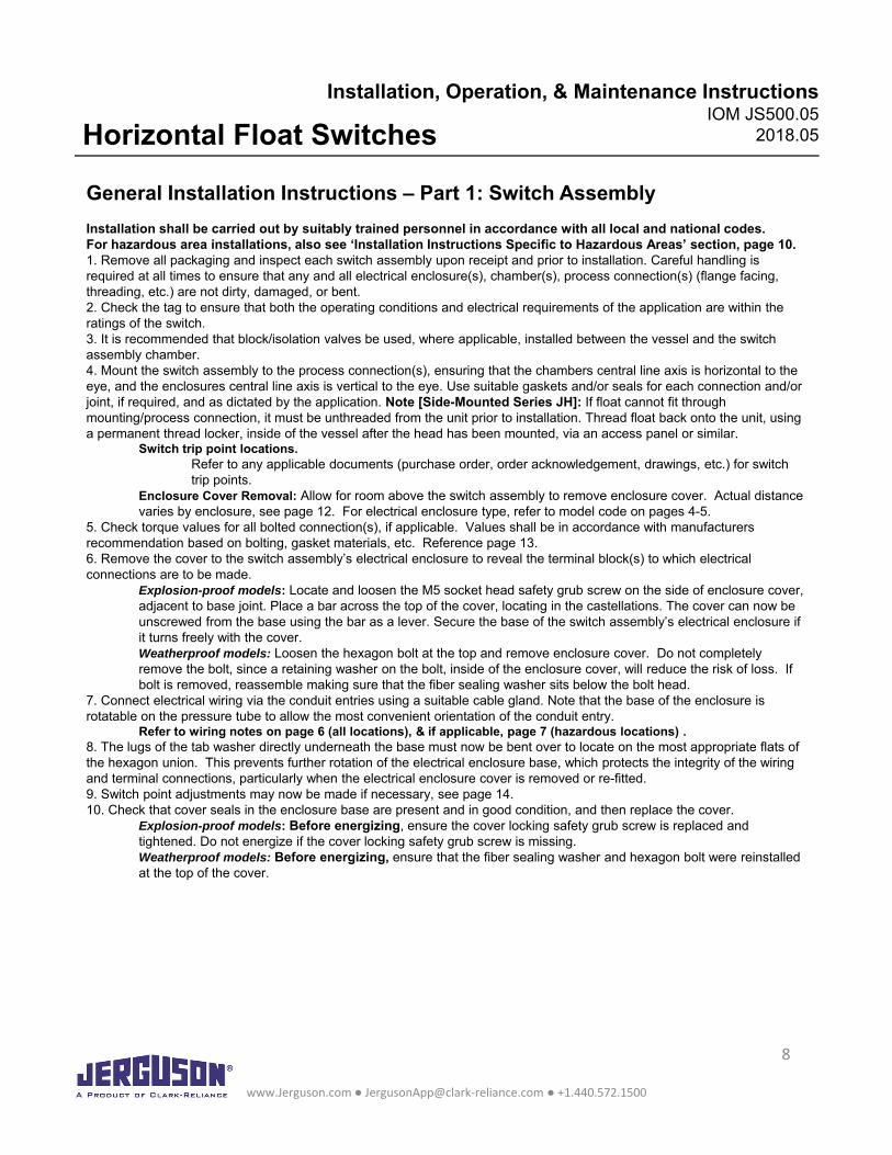
Installation shall be carried out by suitably trained personnel in accordance with all local and national codes.For hazardous area installations, also see ‘Installation Instructions Specific to Hazardous Areas’ section, page 10.1. Remove all packaging and inspect each switch assembly upon receipt and prior to installation. Careful handling is required at all times to ensure that any and all electrical enclosure(s), chamber(s), process connection(s) (flange facing, threading, etc.) are not dirty, damaged, or bent.2. Check the tag to ensure that both the operating conditions and electrical requirements of the application are within the ratings of the switch.3. It is recommended that block/isolation valves be used, where applicable, installed between the vessel and the switch assembly chamber. 4. Mount the switch assembly to the process connection(s), ensuring that the chambers central line axis is horizontal to the eye, and the enclosures central line axis is vertical to the eye. Use suitable gaskets and/or seals for each connection and/or joint, if required, and as dictated by the application. Note [Side-Mounted Series JH]: If float cannot fit through mounting/process connection, it must be unthreaded from the unit prior to installation. Thread float back onto the unit, using a permanent thread locker, inside of the vessel after the head has been mounted, via an access panel or similar.
Switch trip point locations.Refer to any applicable documents (purchase order, order acknowledgement, drawings, etc.) for switch trip points.
Enclosure Cover Removal: Allow for room above the switch assembly to remove enclosure cover. Actual distance varies by enclosure, see page 12. For electrical enclosure type, refer to model code on pages 4-5.
5. Check torque values for all bolted connection(s), if applicable. Values shall be in accordance with manufacturers recommendation based on bolting, gasket materials, etc. Reference page 13.6. Remove the cover to the switch assembly’s electrical enclosure to reveal the terminal block(s) to which electrical connections are to be made.
Explosion-proof models: Locate and loosen the M5 socket head safety grub screw on the side of enclosure cover, adjacent to base joint. Place a bar across the top of the cover, locating in the castellations. The cover can now be unscrewed from the base using the bar as a lever. Secure the base of the switch assembly’s electrical enclosure if it turns freely with the cover.Weatherproof models: Loosen the hexagon bolt at the top and remove enclosure cover. Do not completely remove the bolt, since a retaining washer on the bolt, inside of the enclosure cover, will reduce the risk of loss. If bolt is removed, reassemble making sure that the fiber sealing washer sits below the bolt head.
7. Connect electrical wiring via the conduit entries using a suitable cable gland. Note that the base of the enclosure is rotatable on the pressure tube to allow the most convenient orientation of the conduit entry.
Refer to wiring notes on page 6 (all locations), & if applicable, page 7 (hazardous locations) .8. The lugs of the tab washer directly underneath the base must now be bent over to locate on the most appropriate flats of the hexagon union. This prevents further rotation of the electrical enclosure base, which protects the integrity of the wiring and terminal connections, particularly when the electrical enclosure cover is removed or re-fitted.9. Switch point adjustments may now be made if necessary, see page 14.10. Check that cover seals in the enclosure base are present and in good condition, and then replace the cover.
Explosion-proof models: Before energizing, ensure the cover locking safety grub screw is replaced and tightened. Do not energize if the cover locking safety grub screw is missing.Weatherproof models: Before energizing, ensure that the fiber sealing washer and hexagon bolt were reinstalled at the top of the cover.
www.Jerguson.com ● [email protected] ● +1.440.572.1500
8
Installation, Operation, & Maintenance InstructionsIOM JS500.05
2018.05Horizontal Float Switches
General Installation Instructions – Part 2: Spare Enclosure & Pressure Tube
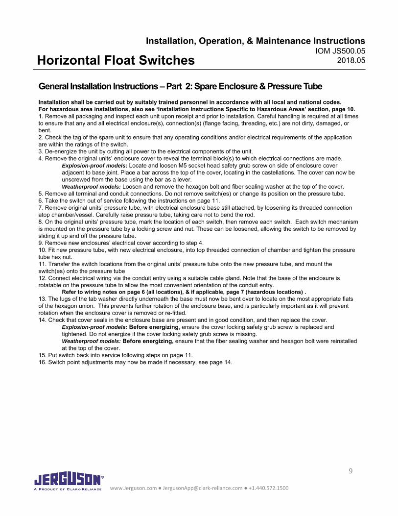
Installation shall be carried out by suitably trained personnel in accordance with all local and national codes.For hazardous area installations, also see ‘Installation Instructions Specific to Hazardous Areas’ section, page 10.1. Remove all packaging and inspect each unit upon receipt and prior to installation. Careful handling is required at all times to ensure that any and all electrical enclosure(s), connection(s) (flange facing, threading, etc.) are not dirty, damaged, or bent.2. Check the tag of the spare unit to ensure that any operating conditions and/or electrical requirements of the application are within the ratings of the switch. 3. De-energize the unit by cutting all power to the electrical components of the unit.4. Remove the original units’ enclosure cover to reveal the terminal block(s) to which electrical connections are made.
Explosion-proof models: Locate and loosen M5 socket head safety grub screw on side of enclosure cover adjacent to base joint. Place a bar across the top of the cover, locating in the castellations. The cover can now be unscrewed from the base using the bar as a lever. Weatherproof models: Loosen and remove the hexagon bolt and fiber sealing washer at the top of the cover.
5. Remove all terminal and conduit connections. Do not remove switch(es) or change its position on the pressure tube.6. Take the switch out of service following the instructions on page 11.7. Remove original units’ pressure tube, with electrical enclosure base still attached, by loosening its threaded connection atop chamber/vessel. Carefully raise pressure tube, taking care not to bend the rod.8. On the original units’ pressure tube, mark the location of each switch, then remove each switch. Each switch mechanism is mounted on the pressure tube by a locking screw and nut. These can be loosened, allowing the switch to be removed by sliding it up and off the pressure tube.9. Remove new enclosures’ electrical cover according to step 4.10. Fit new pressure tube, with new electrical enclosure, into top threaded connection of chamber and tighten the pressure tube hex nut.11. Transfer the switch locations from the original units’ pressure tube onto the new pressure tube, and mount the switch(es) onto the pressure tube 12. Connect electrical wiring via the conduit entry using a suitable cable gland. Note that the base of the enclosure is rotatable on the pressure tube to allow the most convenient orientation of the conduit entry.
Refer to wiring notes on page 6 (all locations), & if applicable, page 7 (hazardous locations) .13. The lugs of the tab washer directly underneath the base must now be bent over to locate on the most appropriate flats of the hexagon union. This prevents further rotation of the enclosure base, and is particularly important as it will prevent rotation when the enclosure cover is removed or re-fitted.14. Check that cover seals in the enclosure base are present and in good condition, and then replace the cover.
Explosion-proof models: Before energizing, ensure the cover locking safety grub screw is replaced and tightened. Do not energize if the cover locking safety grub screw is missing.Weatherproof models: Before energizing, ensure that the fiber sealing washer and hexagon bolt were reinstalled at the top of the cover.
15. Put switch back into service following steps on page 11.16. Switch point adjustments may now be made if necessary, see page 14.
www.Jerguson.com ● [email protected] ● +1.440.572.1500
9
Installation, Operation, & Maintenance InstructionsIOM JS500.05
2018.05Horizontal Float Switches Installation Instructions Specific to Hazardous Area
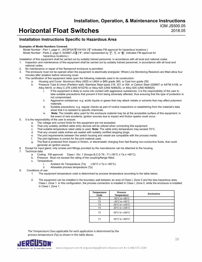
Examples of Model Numbers Covered:Model Number - Part 1, page 4 : JHC8FSA7F1X410X (“F” indicates FM approval for hazardous locations.)Model Number - Parts 2, page 5: S24867-JC# (“#”, when represented by “7”, “I”, or “R”, indicates FM approval for
hazardous locations.)Installation of this equipment shall be carried out by suitably trained personnel, in accordance with all local and national codes.1. Inspection and maintenance of this equipment shall be carried out by suitably trained personnel, in accordance with all local and
national codes.2. No maintenance or repair of the flameproof enclosure is permitted.3. The enclosure must not be opened when the equipment is electrically energized. Where Line Monitoring Resistors are fitted allow four
minutes after isolation before removing cover.4. The certification of this equipment relies upon the following materials used in its construction:
a. Housing and Cover: Aluminum Alloy LM25 or LM24 or B85 grade 360, or Cast Iron grade 250.b. Pressure Tube & Union (Partition wall): Stainless Steel types 316, 321 or 304, or Carbon Steel 220M07 or ASTM A108, or
Alloy NA18, or Alloy C-276 (UNS N10276) or Alloy 625 (UNS N06625), or Alloy 825 (UNS N08825)i. If the equipment is likely to come into contact with aggressive substances, it is the responsibility of the user to
take suitable precautions that prevent it from being adversely affected, thus ensuring that the type of protection is not compromised.
ii. Aggressive substances: e.g. acidic liquids or gases that may attack metals or solvents that may affect polymeric materials.
iii. Suitable precautions: e.g. regular checks as part of routine inspections or establishing from the material’s data sheet that it is resistant to specific chemicals.
iv. Note: The metallic alloy used for the enclosure material may be at the accessible surface of this equipment; in the event of rare accidents, ignition sources due to impact and friction sparks could occur.
5. It is the responsibility of the user to ensure:a. The voltage and current limits for this equipment are not exceeded.b. That only suitably certified cable entry devices will be utilized when connecting this equipment.c. That suitable temperature rated cable is used. Note: The cable entry temperature may exceed 70°C.d. That any unused cable entries are sealed with suitably certified stopping plugs.e. The joint requirements between the switch housing and vessel are compatible with the process media.f. The joint tightness is correct for the joint material used.g. The float is protected from impact or friction, or electrostatic charging from fast flowing non-conductive fluids, that could
generate an ignition source.6. Except for input gland, only screws and fittings provided by the manufacturer can be attached to the housing.7. Technical data:
a. Coding: FM approval: Class I Div. 1 Groups B,C,D T6...T1 (-50°C ≤ Ta ≤ +60°C)b. Pressure: Must not exceed the rating of the coupling/flange fitted.c. Temperature:
i. Ambient Air Temperature (Ta) (-50°C ≤ Ta ≤ +60°C) ii. Allowable process temperature (Tp)
8. Conditions of use: 1. The equipment temperature code is determined by process temperature according to the table below.
2. The equipment can be installed in the boundary wall between an area of Class I, Zone 0 and the less hazardous area, Class I, Zone 1. In this configuration, the process connection is installed in Class I, Zone 0, while the enclosure is installedin Class I, Zone 1.
The Temperature Class applicable for each application is determined by theprocess temperature (Tp) as shown in the table above.
www.Jerguson.com ● [email protected] ● +1.440.572.1500
10
Temperature Code
Process Temperature
Exclusions
T6 -50°C to +80°CT5 -50°C to +95°CT4 -50°C to +130°CT3 -50°C to +195°C
T2 -50°C to +295°C
T1 -50°C to +400°C
Installation, Operation, & Maintenance InstructionsIOM JS500.05
2018.05Horizontal Float Switches
Putting the Switch into Service
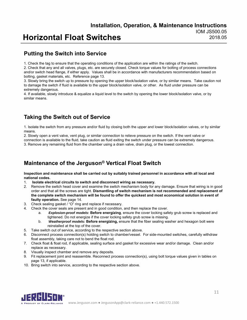
1. Check the tag to ensure that the operating conditions of the application are within the ratings of the switch.2. Check that any and all valves, plugs, etc. are securely closed. Check torque values for bolting of process connections and/or switch head flange, if either apply. Values shall be in accordance with manufacturers recommendation based on bolting, gasket materials, etc. Reference page 13.3. Slowly bring the switch up to pressure by opening the upper block/isolation valve, or by similar means. Take caution not to damage the switch if fluid is available to the upper block/isolation valve, or other. As fluid under pressure can be extremely dangerous.4. If available, slowly introduce & equalize a liquid level to the switch by opening the lower block/isolation valve, or by similar means.
Taking the Switch out of Service
1. Isolate the switch from any pressure and/or fluid by closing both the upper and lower block/isolation valves, or by similar means.2. Slowly open a vent valve, vent plug, or similar connection to relieve pressure on the switch. If the vent valve or connection is available to the fluid, take caution as fluid exiting the switch under pressure can be extremely dangerous.3. Remove any remaining fluid from the chamber using a drain valve, drain plug, or the lowest connection.
Maintenance of the Jerguson® Vertical Float Switch
Inspection and maintenance shall be carried out by suitably trained personnel in accordance with all local and national codes.1. Isolate electrical circuits to switch and disconnect wiring as necessary.2. Remove the switch head cover and examine the switch mechanism body for any damage. Ensure that wiring is in good
order and that all the screws are tight. Dismantling of switch mechanism is not recommended and replacement of the complete switch mechanism will be found to offer the quickest and most economical solution in event of faulty operation. See page 14.
3. Check sealing gasket / “O” ring and replace if necessary.4. Check the cover seals are present and in good condition, and then replace the cover.
a. Explosion-proof models: Before energizing, ensure the cover locking safety grub screw is replaced and tightened. Do not energize if the cover locking safety grub screw is missing.
b. Weatherproof models: Before energizing, ensure that the fiber sealing washer and hexagon bolt were reinstalled at the top of the cover.
5. Take switch out of service, according to the respective section above.6. Disconnect process connection(s) holding switch to chamber/vessel. For side-mounted switches, carefully withdraw
float assembly, taking care not to bend the float rod.7. Check float & float rod, if applicable, sealing surface and gasket for excessive wear and/or damage. Clean and/or
replace as necessary.8. Visually inspect chamber and remove any deposits.9. Fit replacement joint and reassemble. Reconnect process connection(s), using bolt torque values given in tables on
page 13, if applicable.10. Bring switch into service, according to the respective section above.
www.Jerguson.com ● [email protected] ● +1.440.572.1500
11
Installation, Operation, & Maintenance InstructionsIOM JS500.05
2018.05Horizontal Float Switches
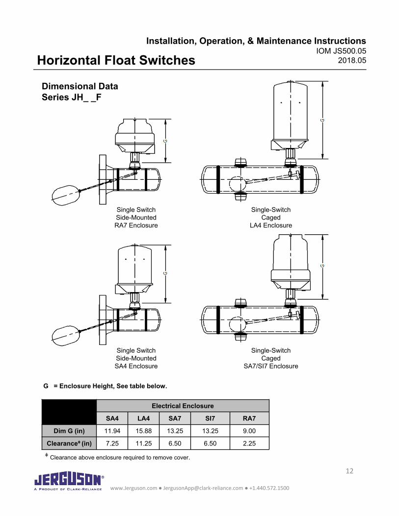
Dimensional DataSeries JH_ _F
Single SwitchSide-MountedRA7 Enclosure
Single SwitchSide-MountedSA4 Enclosure
Single-SwitchCaged
LA4 Enclosure
Single-SwitchCaged
SA7/SI7 Enclosure
www.Jerguson.com ● [email protected] ● +1.440.572.1500
12
Electrical Enclosure
SA4 LA4 SA7 SI7 RA7
Dim G (in) 11.94 15.88 13.25 13.25 9.00
Clearanceǂ (in) 7.25 11.25 6.50 6.50 2.25
ǂ Clearance above enclosure required to remove cover.
G = Enclosure Height, See table below.
Installation, Operation, & Maintenance InstructionsIOM JS500.05
2018.05Horizontal Float Switches
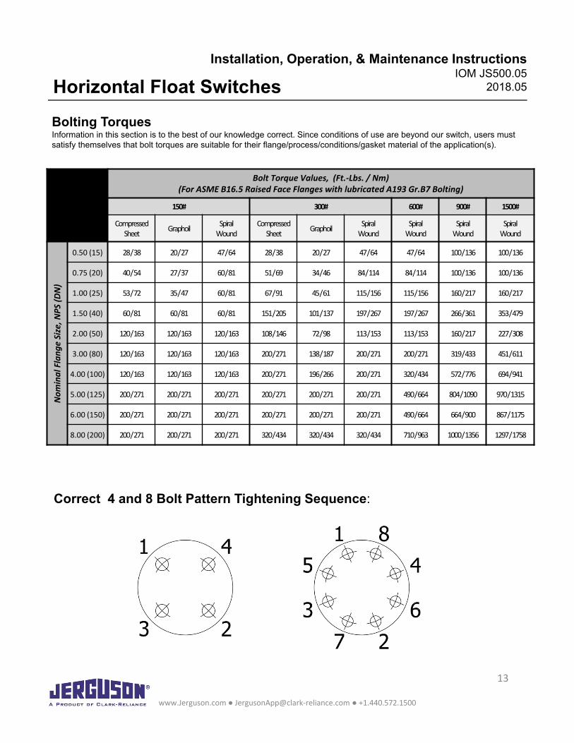
Bolting TorquesInformation in this section is to the best of our knowledge correct. Since conditions of use are beyond our switch, users must satisfy themselves that bolt torques are suitable for their flange/process/conditions/gasket material of the application(s).
Bolt Torque Values, (Ft.-Lbs. / Nm)(For ASME B16.5 Raised Face Flanges with lubricated A193 Gr.B7 Bolting)
150# 300# 600# 900# 1500#
Compressed Sheet Graphoil Spiral
WoundCompressed
Sheet Graphoil Spiral Wound
Spiral Wound
Spiral Wound
Spiral Wound
Nom
inal
Fla
nge
Size
,NPS
(DN
)
0.50 (15) 28 / 38 20 / 27 47 / 64 28 / 38 20 / 27 47 / 64 47 / 64 100 / 136 100 / 136
0.75 (20) 40 / 54 27 / 37 60 / 81 51 / 69 34 / 46 84 / 114 84 / 114 100 / 136 100 / 136
1.00 (25) 53 / 72 35 / 47 60 / 81 67 / 91 45 / 61 115 / 156 115 / 156 160 / 217 160 / 217
1.50 (40) 60 / 81 60 / 81 60 / 81 151 / 205 101 / 137 197 / 267 197 / 267 266 / 361 353 / 479
2.00 (50) 120 / 163 120 / 163 120 / 163 108 / 146 72 / 98 113 / 153 113 / 153 160 / 217 227 / 308
3.00 (80) 120 / 163 120 / 163 120 / 163 200 / 271 138 / 187 200 / 271 200 / 271 319 / 433 451 / 611
4.00 (100) 120 / 163 120 / 163 120 / 163 200 / 271 196 / 266 200 / 271 320 / 434 572 / 776 694 / 941
5.00 (125) 200 / 271 200 / 271 200 / 271 200 / 271 200 / 271 200 / 271 490 / 664 804 / 1090 970 / 1315
6.00 (150) 200 / 271 200 / 271 200 / 271 200 / 271 200 / 271 200 / 271 490 / 664 664 / 900 867 / 1175
8.00 (200) 200 / 271 200 / 271 200 / 271 320 / 434 320 / 434 320 / 434 710 / 963 1000 / 1356 1297 / 1758
Correct 4 and 8 Bolt Pattern Tightening Sequence:
www.Jerguson.com ● [email protected] ● +1.440.572.1500
13
Installation, Operation, & Maintenance InstructionsIOM JS500.05
2018.05Horizontal Float Switches
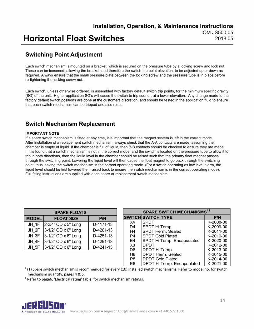
MODEL FLOAT SIZE P/NJH_1F 2-3/4" OD x 5" Long D-4171-13JH_2F 3-1/2" OD x 6" Long D-4261-13JH_3F 3-1/2" OD x 6" Long D-4251-13JH_4F 3-1/2" OD x 6" Long D-4291-13JH_5F 3-1/2" OD x 6" Long D-4241-13
SPARE FLOATS SWITCH SWITCH TYPE P/N
X4 SPDT K-2008-00D4 SPDT Hi Temp. K-2009-00H4 SPDT Herm. Sealed K-2011-00P4 SPDT Gold Plated K-2010-00E4 SPDT Hi Temp. Encapsulated K-2020-00X8 DPDT K-2012-00D8 DPDT Hi Temp. K-2013-00H8 DPDT Herm. Sealed K-2015-00P8 DPDT Gold Plated K-2014-00E8 DPDT Hi Temp. Encapsulated K-2021-00
SPARE SWITCH MECHANISMS12
Switching Point Adjustment
Each switch mechanism is mounted on a bracket, which is secured on the pressure tube by a locking screw and lock nut. These can be loosened, allowing the bracket, and therefore the switch trip point elevation, to be adjusted up or down as required. Always ensure that the small pressure plate between the locking screw and the pressure tube is in place before re-tightening the locking screw nut.
Each switch, unless otherwise ordered, is assembled with factory default switch trip points, for the minimum specific gravity(SG) of the unit. Higher application SG’s will cause the switch to trip sooner, at a lower elevation. Any change made to the factory default switch positions are done at the customers discretion, and should be tested in the application fluid to ensure that each switch mechanism can be tripped and also reset.
Switch Mechanism Replacement
IMPORTANT NOTEIf a spare switch mechanism is fitted at any time, it is important that the magnet system is left in the correct mode.After installation of a replacement switch mechanism, always check that the A-A contacts are made, assuming the chamber is empty of liquid. If the chamber is full of liquid, then B-B contacts should be checked to ensure they are made.If it is found that a switch mechanism is not in the correct mode, and the switch is located on the pressure tube to allow it to trip in both directions, then the liquid level in the chamber should be raised such that the primary float magnet passes through the switching point. Lowering the liquid level will then cause the float magnet to go back through the switching point, thus leaving the switch mechanism in the correct operating mode. (For a switch operating as low level alarm, the liquid level should be first lowered then raised back to ensure the switch mechanism is in the correct operating mode).Full fitting instructions are supplied with each spare or replacement switch mechanism.
www.Jerguson.com ● [email protected] ● +1.440.572.1500
14
1 (1) Spare switch mechanism is recommended for every (10) installed switch mechanisms. Refer to model no. for switchmechanism quantity, pages 4 & 5.
2 Refer to page6, 'Electrical rating' table, for switch mechanism ratings.
Installation, Operation, & Maintenance InstructionsIOM JS500.05
2018.05Horizontal Float Switches
15
Installation, Operation, & Maintenance InstructionsIOM JS500.05
2018.05Horizontal Float Switches
16633 Foltz Parkway, Strongsville, OH 44149 USA+1.440.572.1500 www.clarkreliance.com
www.Jerguson.com ● [email protected] ● +1.440.572.1500
16