Horizontal Fiberglass Pumps - pumpfundamentals.com · Horizontal Fiberglass Pumps. FYBROC – THE...
16
Fybroc Division SERIES 1500 ANSI/ASME SPECIFICATION B73.1 B ULLETIN 15B1 Horizontal Fiberglass Pumps
Transcript of Horizontal Fiberglass Pumps - pumpfundamentals.com · Horizontal Fiberglass Pumps. FYBROC – THE...
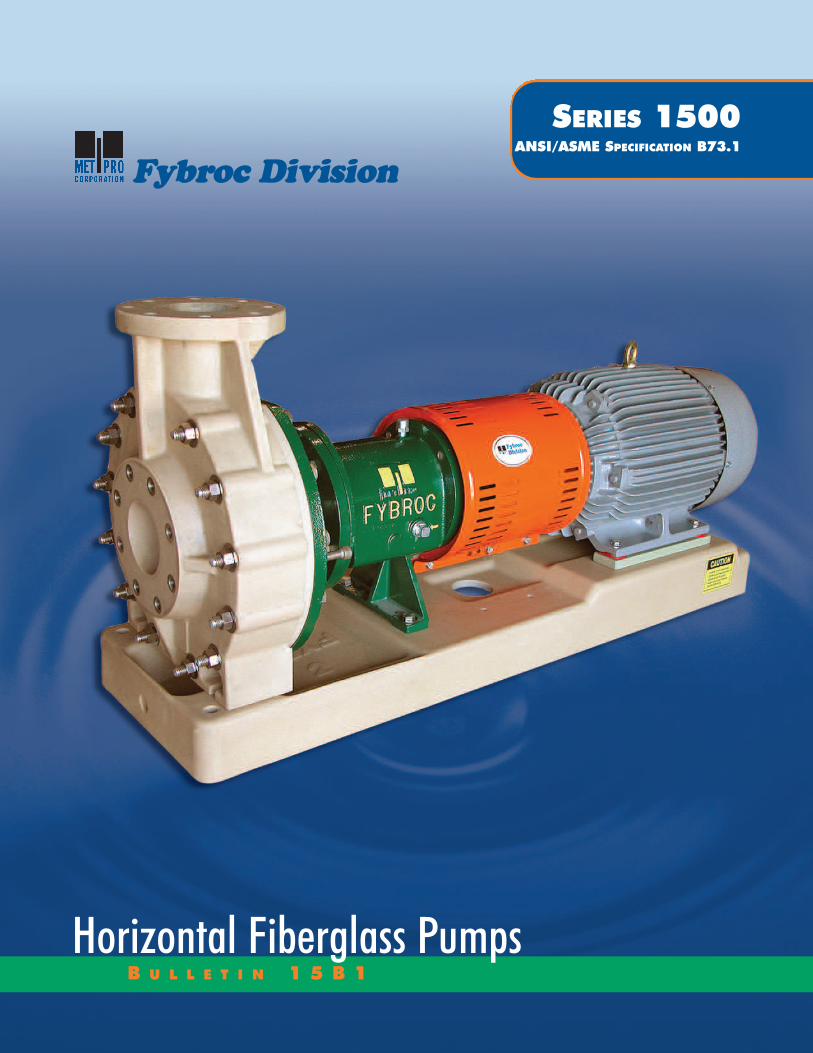
Fybroc Division
SERIES 1500 ANSI/ASME SPECIFICATION B73.1
B U L L E T I N 1 5 B 1Horizontal Fiberglass Pumps
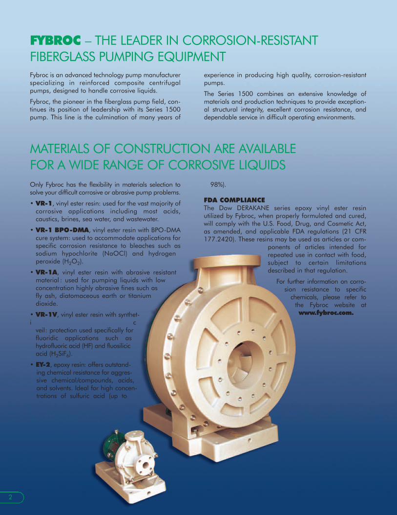
FYBROC – THE LEADER IN CORROSION-RESISTANT FIBERGLASS PUMPING EQUIPMENTFybroc is an advanced technology pump manufacturerspecializing in reinforced composite centrifugalpumps, designed to handle corrosive liquids.
Fybroc, the pioneer in the fiberglass pump field, con-tinues its position of leadership with its Series 1500pump. This line is the culmination of many years of
experience in producing high quality, corrosion-resistantpumps.
The Series 1500 combines an extensive knowledge ofmaterials and production techniques to provide exception-al structural integrity, excellent corrosion resistance, anddependable service in difficult operating environments.
2
MATERIALS OF CONSTRUCTION ARE AVAILABLE FOR A WIDE RANGE OF CORROSIVE LIQUIDSOnly Fybroc has the flexibility in materials selection tosolve your difficult corrosive or abrasive pump problems.
• VR-1, vinyl ester resin: used for the vast majority of corrosive applications including most acids, caustics, brines, sea water, and wastewater.
• VR-1 BPO-DMA, vinyl ester resin with BPO-DMA cure system: used to accommodate applications for specific corrosion resistance to bleaches such as sodium hypochlorite (NaOCl) and hydrogen peroxide (H2O2).
• VR-1A, vinyl ester resin with abrasive resistant material : used for pumping liquids with low concentration highly abrasive fines such as fly ash, diatomaceous earth or titanium dioxide.
• VR-1V, vinyl ester resin with synthet-i c
veil: protection used specifically for fluoridic applications such as hydrofluoric acid (HF) and fluosilicicacid (H2SiF6).
• EY-2, epoxy resin: offers outstand-ing chemical resistance for aggres-sive chemical/compounds, acids,and solvents. Ideal for high concen-trations of sulfuric acid (up to
98%).
FDA COMPLIANCEThe Dow DERAKANE series epoxy vinyl ester resin utilized by Fybroc, when properly formulated and cured,will comply with the U.S. Food, Drug, and Cosmetic Act,as amended, and applicable FDA regulations (21 CFR177.2420). These resins may be used as articles or com-
ponents of articles intended forrepeated use in contact with food,subject to certain limitationsdescribed in that regulation.
For further information on corro-sion resistance to specific
chemicals, please refer tothe Fybroc website atwww.fybroc.com.

FYBROC SERIES 1500 THERMOSET CONSTRUCTIONRESIN TRANSFER MOLDING (RTM) PROCESS FORSUPERIOR STRENGTH AND CORROSION RESISTANCEThermoset fiberglass reinforced plastic (FRP) pumps areincreasingly being used in the pump industry due to theirlow weight, durability, and tailor-made properties. A ther-moset is a material that cures or hardens (sets) into agiven shape, generally through the reaction with a cata-lyst. Curing is an irreversible chemical reaction in whichpermanent connections (cross-links) are made between amaterial’s molecular chains. The cross-links give thecured polymer a three-dimensional structure, as well as ahigher degree of rigidity than it possessed prior to curing.
It is important to note that a thermoset material will notre-melt or otherwise regain the processibility it hadbefore being cured. Thermoset materials outperformother materials (thermoplastics, for example) in a number of areas, including the following: mechanicalproperties, chemical resistance, thermal stability, andoverall durability.
The fiberglass components in the Series 1500 Seriespumps, as well as Fybroc’s complete line of centrifugalpumps, utilize the Resin Transfer Molding process. Thisprocess allows for the controlled placement of continu-ous-strand fiberglass mat in high stress areas.Specifically, sheets of contin-uous-strand fiberglassmat are die cut intospecific shapes andthen loaded intomatched-metal diemolds. After load-ing, the molds areclosed and theninjected with cat-alyzed resin into a sin-gle inlet port withnumerous vent ports toensure complete air displace-ment. After the resin gels, the part is removed andallowed to cure at ambient temperature, and then thepart is post-cured in a controlled heat operation. Themajor advantage of the RTM process, unlike a
compression molded process that inherently utilizesrandomly oriented pieces of chopped fiberglass leadingto comparatively lower strength, is that the carefully ori-ented continuous-strand fiberglass mat provides com-ponents with excellent physical strength and properties.In addition, the process allows for the design of thinner-walled structures, thereby permitting the use of nearlypure resin systems for optimum corrosion resistance.The bottom line is that RTM is a manufacturing tech-nique that optimizes both strength and corrosion resist-ance.
Critical components such as the single-piece casing, withits heavily gusseted suction and discharge flanges, bene-fit from the reinforcing properties of the RTM process. Thispermits the handling of normal pipe loads under fullworking pressures. Furthermore, this method of rein-forcement in the impeller extends the life of this compo-nent and provides unparalled strength without degrada-tion in corrosive environments.
With more than thirty years of composite pump designand manufacturing experience, Fybroc has the expertiseto provide you with a composite pump line of the highestquality and durability for your specific service or applica-tion. Remember, FRP pumps are our ONLY business! Bycontrolling the entire manufacturing process in-house,Fybroc is able to offer flexibility with special customerrequirements while boasting the best lead times in theindustry.
3
CORROSION-RESISTANT FIBERGLASS BASEPLATESFybroc manufactures fiberglass baseplates since chem-ical pumps are often used and installed in environ-ments where external corrosion can be a serious prob-
lem. The baseplates are constructed of fiberglass-rein-forced vinyl ester resin utilizing continuous- strand rein-forcement for maximum strength and stiffness. In addi-tion, they accommodate ANSI/ASME dimensionedpumps (and NEMA/IEC motors) with an integral,sloped drip pan under the pump, a tapped drain con-nection, and a provision for a grouted foundation.Refer to page 13 for additional baseplate informationand specifications.
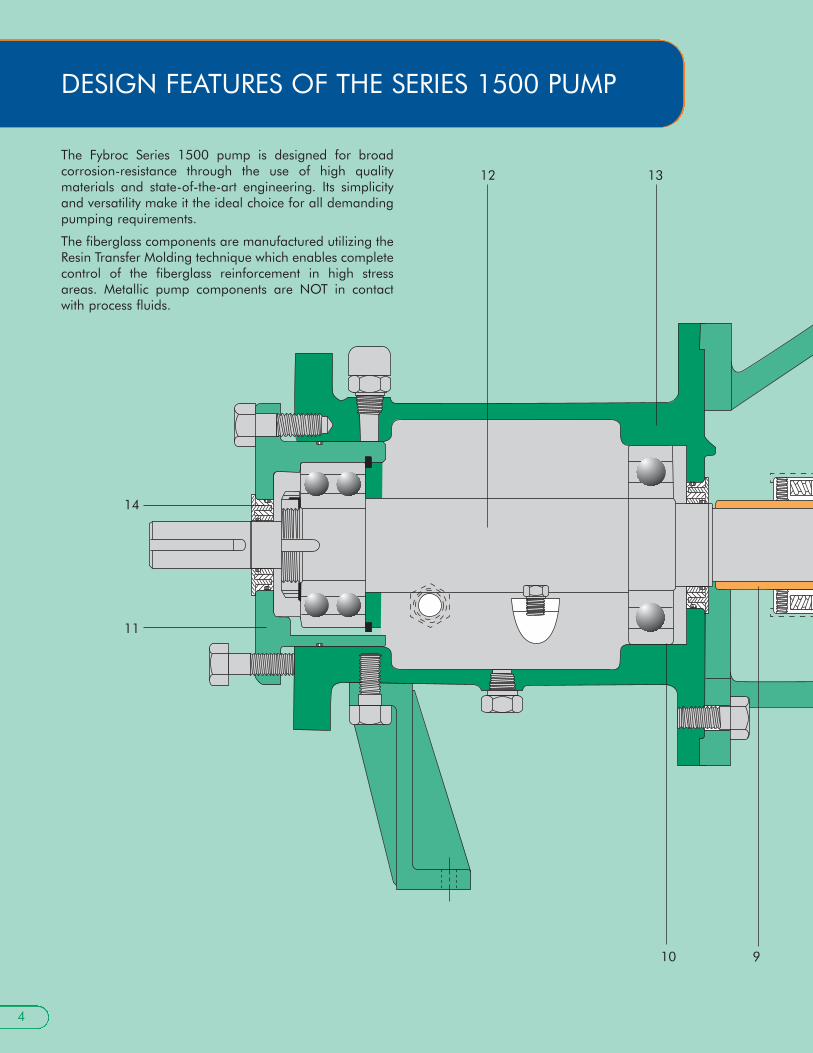
DESIGN FEATURES OF THE SERIES 1500 PUMP
The Fybroc Series 1500 pump is designed for broad corrosion-resistance through the use of high quality materials and state-of-the-art engineering. Its simplicityand versatility make it the ideal choice for all demandingpumping requirements.
The fiberglass components are manufactured utilizing theResin Transfer Molding technique which enables completecontrol of the fiberglass reinforcement in high stressareas. Metallic pump components are NOT in contactwith process fluids.
14
11
10 9
12 13
4

1. ANSI/ASME B73.1 CONFOR-MANCE ensures maximum interchange-ability with existing metal ANSI pumps,thereby eliminating any need for pipingor foundation changes when up-gradingan installation to Fybroc Series 1500pumps.
2. SMOOTH HYDRAULIC PASSAGESpromote increased pump efficiency.
3. SINGLE ONE-PIECE GUSSETEDCASINGeasily withstands the rigors of normalplant piping loads.
4. IMPELLER PUMP-OUT VANES and relief holes minimize axial unbalanceand lower stuffing box pressure.
5. ALLOY INSERT (integrally molded withimpeller) with rounded edges carriesimpeller torque loads with low stress.
6. VERSATILE CASING COVER is suit-able for use with most single outside ordouble inside mechanical seals withoutmodifications. See page 7 for some ofthe most frequently used configurationsand page 8 for seal flush considera-tions.
7. CONTINUOUS-STRAND FIBER-GLASS CONSTRUCTION for all wet-ted parts in either vinyl ester or epoxyresin provides maximum corrosion resist-ance for a wide range of difficult liquids.
8. CASING THROUGH-BOLTS maintain casing o-ring seal integrity under allhydraulic operating conditions.
9. INTEGRAL SHAFT SLEEVE design eliminates gaskets and o-rings and protects the pump shaft from exposure tothe process fluid.
10. LARGE-CAPACITY BEARINGS ensureoperating life well in excess of the minimum specified by ANSI/ASMEB73.1.
11. EXTERNAL IMPELLER ADJUST-MENT allows field setting of impeller-to-casing clearance.
12. HEAVY-DUTY SHAFT minimizesdeflec-tion to maximize mechanical seallife.
13. POLYESTER THERMOSETTINGPOWDER COATED POWER FRAMEcomponents prevent external corrosion.
14. LABYRINTH OIL SEALS nickel plated-bronze for longer life. Improved oilcontainment.
8
7
6
5
4
3
2
1
5

The Series 1500 pumps have been designed to maximizethe life of bearings and mechanical seals which can deteriorate because of shaft deflection resulting from radial thrust. Radial thrust is the force acting on the sideof an impeller as a result of the non-uniform distributionof pressure around the pump casing at off-peak opera-tion.
The magnitude of this thrust varies with the flow, but theamount of radial thrust can roughly be cut in half by uti-lizing a double volute casing. The solid line in the chart tothe right depicts the typical radial thrust characteristic of asingle volute casing. The dotted line portrays the use of adouble volute casing and the resulting reduction in radialthrust.
The drawing at lower right shows the location of the “cutwater” in volute casings. The cutwater is the closeclearance extension of the casing located at the base ofthe volute. Also, shown in orange, is the second cutwateror “splitter” used in the double volute casing, whichchannels half of the flow to the pump discharge. The split-ter reduces the pressure imbalance in the casing duringoff-peak flows and reduces both radial thrust and itsresulting shaft deflection. Fybroc uses double volute cas-ings in eleven of its larger pump sizes where, typically,radial thrust loadings are higher. See chart on page 9,Casing Data, Volute.
MATERIALS OF CONSTRUCTION
100
90
80
70
60
50
40
30
20
10
00 10 20 30 40 50 60 70 80 90 100 110 120 130 140
% OF DESIGN FLOW
% O
F M
AXI
MU
M R
AD
IAL
THRU
ST
Double Volute
Single Volute
Splitter
Cutwater
Consult Factory for materials availability for your specific pump size.
6
DESIGN PROVIDES FOR MAXIMUMSEAL AND BEARING LIFE
COMPONENT MATERIALS
Casing VR-1, VR-1 BPO-DMA, VR-1A, VR-1V, EY-2
Impeller VR-1, VR-1 BPO-DMA, VR-1A, VR-1V, EY-2
Cover VR-1, VR-1 BPO-DMA, VR-1A, VR-1V, EY-2
Gland VR-1, VR-1 BPO-DMA, EY-2
Shaft 303SS (Optional 316SS)
Bearing Hsg. Polyester Thermosetting Powder Coated Iron
Adapter Polyester Thermosetting Powder Coated Iron
Hardware 303SS (Optional hardware is available)
O-Rings Viton A (Optional elastomers are available)

Fybroc Series 1500 pumps are available with a wide variety of mechanical seal arrangements. For corro-sive fluid handling, single outside and double inside seals are recommended. The single outside seals havenon-metallic wetted parts and all metal components located outside the pump. The double inside mechan-ical seals have metallic parts that are exposed to buffer fluid only and are designed to limit the process fluidcontact to non-metallic components.
The following illustrations outline some commonly used sealing arrangements. See page 8 for seal flush con-siderations. Additional mechanical seal configurations (for example, cartridge designs) are available as options.
CRANE 8B2 FLOWSERVE RAC
CRANE TYPE 8-1T FLOWSERVE RXO
7
MECHANICAL SEAL
INTEGRAL IMPELLER AND
• “ONE-PIECE” impeller and shaft sleeve
• “NO” shaft sleeve o-rings required
• Semi-open type with pump-out vanes and bal-ance holes designed to minimize axial unbalanceand lower stuffing box pressure
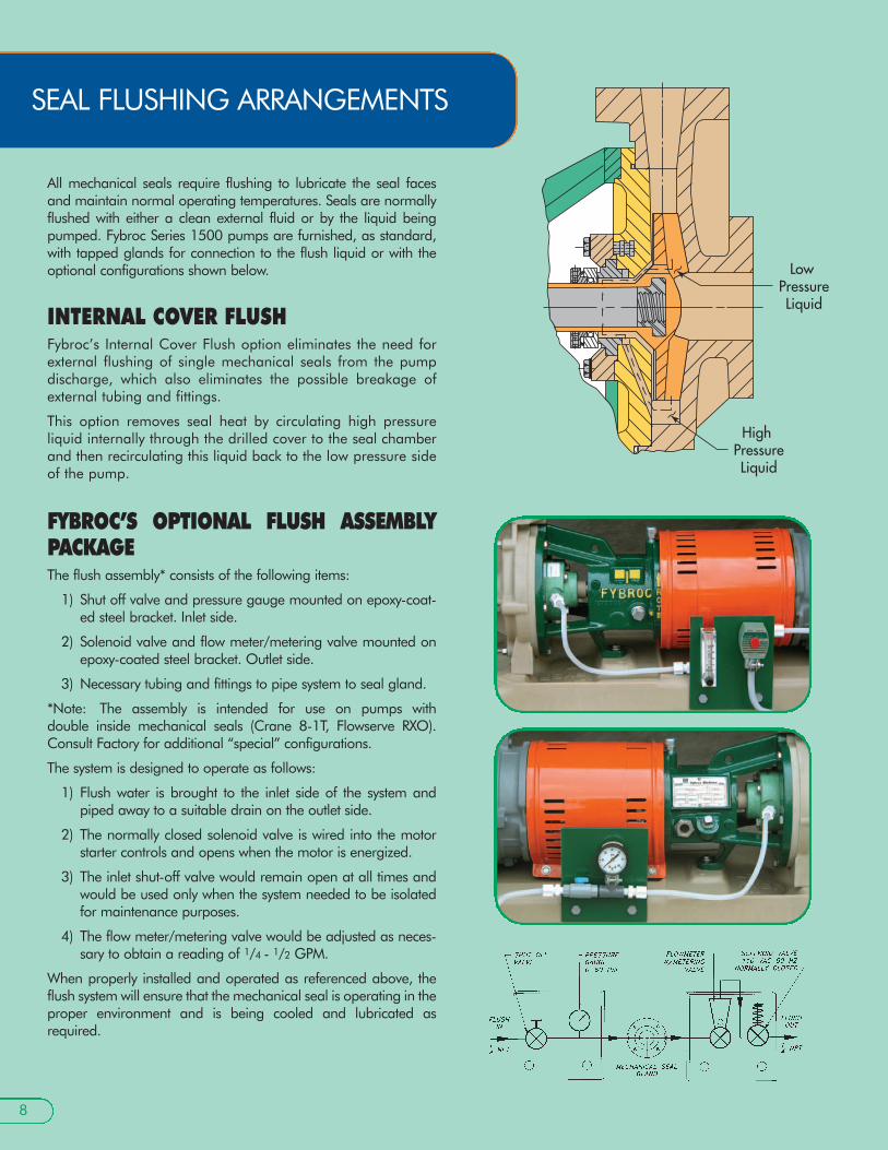
All mechanical seals require flushing to lubricate the seal facesand maintain normal operating temperatures. Seals are normallyflushed with either a clean external fluid or by the liquid beingpumped. Fybroc Series 1500 pumps are furnished, as standard,with tapped glands for connection to the flush liquid or with theoptional configurations shown below.
INTERNAL COVER FLUSHFybroc’s Internal Cover Flush option eliminates the need forexternal flushing of single mechanical seals from the pump discharge, which also eliminates the possible breakage ofexternal tubing and fittings.
This option removes seal heat by circulating high pressure liquid internally through the drilled cover to the seal chamberand then recirculating this liquid back to the low pressure sideof the pump.
FYBROC’S OPTIONAL FLUSH ASSEMBLYPACKAGEThe flush assembly* consists of the following items:
1) Shut off valve and pressure gauge mounted on epoxy-coat-ed steel bracket. Inlet side.
2) Solenoid valve and flow meter/metering valve mounted onepoxy-coated steel bracket. Outlet side.
3) Necessary tubing and fittings to pipe system to seal gland.
*Note: The assembly is intended for use on pumps with double inside mechanical seals (Crane 8-1T, Flowserve RXO).Consult Factory for additional “special” configurations.
The system is designed to operate as follows:
1) Flush water is brought to the inlet side of the system andpiped away to a suitable drain on the outlet side.
2) The normally closed solenoid valve is wired into the motorstarter controls and opens when the motor is energized.
3) The inlet shut-off valve would remain open at all times andwould be used only when the system needed to be isolatedfor maintenance purposes.
4) The flow meter/metering valve would be adjusted as neces-sary to obtain a reading of 1/4 - 1/2 GPM.
When properly installed and operated as referenced above, theflush system will ensure that the mechanical seal is operating in theproper environment and is being cooled and lubricated asrequired.
Low PressureLiquid
High PressureLiquid
8
SEAL FLUSHING ARRANGEMENTS
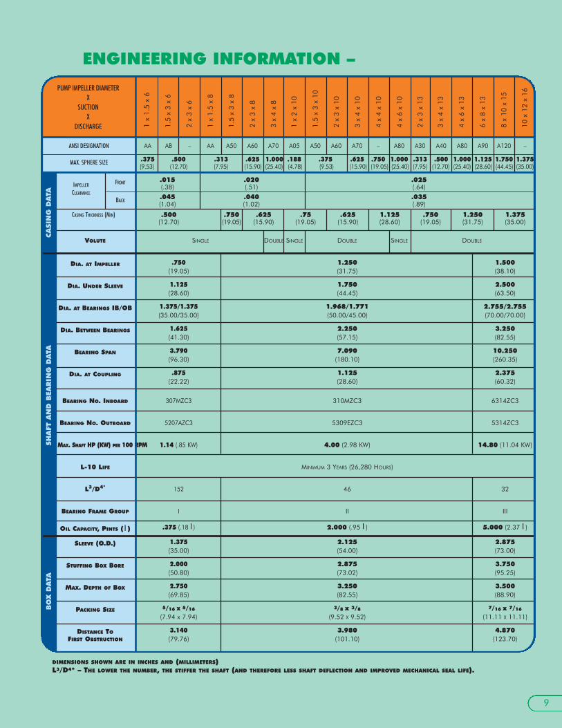
DIMENSIONS SHOWN ARE IN INCHES AND (MILLIMETERS)L3/D4* – THE LOWER THE NUMBER, THE STIFFER THE SHAFT (AND THEREFORE LESS SHAFT DEFLECTION AND IMPROVED MECHANICAL SEAL LIFE).
9
IMPELLER FRONT .015 .020 .025(.38) (.51) (.64)
CLEARANCE
BACK.045 .040 .035(1.04) (1.02) (.89)
CASING THICKNESS (MIN) .500 .750 .625 .75 .625 1.125 .750 1.250 1.375(12.70) (19.05) (15.90) (19.05) (15.90) (28.60) (19.05) (31.75) (35.00)
VOLUTE SINGLE DOUBLE SINGLE DOUBLE SINGLE DOUBLE
DIA. AT IMPELLER .750 1.250 1.500(19.05) (31.75) (38.10)
DIA. UNDER SLEEVE 1.125 1.750 2.500(28.60) (44.45) (63.50)
DIA. AT BEARINGS IB/OB 1.375/1.375 1.968/1.771 2.755/2.755(35.00/35.00) (50.00/45.00) (70.00/70.00)
DIA. BETWEEN BEARINGS 1.625 2.250 3.250(41.30) (57.15) (82.55)
BEARING SPAN 3.790 7.090 10.250(96.30) (180.10) (260.35)
DIA. AT COUPLING .875 1.125 2.375(22.22) (28.60) (60.32)
BEARING NO. INBOARD 307MZC3 310MZC3 6314ZC3
BEARING NO. OUTBOARD 5207AZC3 5309EZC3 5314ZC3
MAX. SHAFT HP (KW) PER 100 RPM 1.14 (.85 KW) 4.00 (2.98 KW) 14.80 (11.04 KW)
L-10 LIFE MINIMUM 3 YEARS (26,280 HOURS)
L3/D4* 152 46 32
BEARING FRAME GROUP I II III
OIL CAPACITY, PINTS ( l ) .375 (.18 l ) 2.000 (.95 l ) 5.000 (2.37 l )
SLEEVE (O.D.) 1.375 2.125 2.875(35.00) (54.00) (73.00)
STUFFING BOX BORE 2.000 2.875 3.750(50.80) (73.02) (95.25)
MAX. DEPTH OF BOX 2.750 3.250 3.500(69.85) (82.55) (88.90)
PACKING SIZE 5/16 x 5/16 3/8 x 3/8 7/16 x 7/16
(7.94 x 7.94) (9.52 X 9.52) (11.11 X 11.11)
DISTANCE TO 3.140 3.980 4.870FIRST OBSTRUCTION (79.76) (101.10) (123.70)
ENGINEERING INFORMATION –
1 x
1.5
x 6
1.5
x 3
x 6
2 x
3 x
6
1 x
1.5
x 8
1.5
x 3
x 8
2 x
3 x
8
3 x
4 x
8
1 x
2 x
10
1.5
x 3
x 10
2 x
3 x
10
3 x
4 x
10
4 x
4 x
10
4 x
6 x
10
2 x
3 x
13
3 x
4 x
13
4 x
6 x
13
6 x
8 x
13
8 x
10 x
15
10 x
12
x 16
PUMP IMPELLER DIAMETERX
SUCTIONX
DISCHARGE
ANSI DESIGNATION AA AB – AA A50 A60 A70 A05 A50 A60 A70 – A80 A30 A40 A80 A90 A120 –
MAX. SPHERE SIZE .375 .500 .313 .625 1.000 .188 .375 .625 .750 1.000 .313 .500 1.000 1.125 1.750 1.375(9.53) (12.70) (7.95) (15.90) (25.40) (4.78) (9.53) (15.90) (19.05) (25.40) (7.95) (12.70) (25.40) (28.60) (44.45) (35.00)
CA
SIN
G D
ATA
BO
X D
ATA
SH
AFT
AN
D B
EAR
ING
DA
TA

1150 RPM60 HERTZ
1750 RPM60 HERTZ
3500 RPM60 HERTZ
NOTE: For specific performancecurves refer to curve bookor www.fybroc.com.
1X11/2X611/2X3X6
2X3X6
3X4X8
2X3X811/2X3X81X11/2X8
1X2X10
2X3X13
11/2X3X102X3X10
3X4X10 4X4X10
4X6X10
3X4X13
4X6X136X8X13
8X10X15
10X12X16
1 2 3 5 10 15 20 30 40 60 80 100 150 200
CUBIC METERS PER HOUR
0 10 20 30 50 100 150 200 300 500 1000 2000 4000 6000
300 500 700 1000 1500
150
100
80
6050
40
30
20
10
5
35302520
15
10
5
2
TOTA
L H
EAD
IN M
ETER
S
1 2 3 5 10 15 20 30 40 60 80 100 150 200
CUBIC METERS PER HOUR
0 10 20 30 50 100 150 200 300 500 1000 2000 4000 6000
300 500 700 1000 1500
250
200
150
100
80
605040
30
20
10
706050
40
302520
15
10
5
TOTA
L H
EAD
IN M
ETER
S
1X11/2X6
11/2X3X6
2X3X6
3X4X8
2X3X811/2X3X81X11/2X8
1X2X10
2X3X13
11/2X3X102X3X10
3X4X10 4X4X10
4X6X10
3X4X134X6X13 6X8X13
8X10X15
1 2 3 5 10 15 20 30 40 60 80
CUBIC METERS PER HOUR
0 5 10 20 30 40 50 100 150 200 300 500 1000 2000
100 150 200 300
600500
400
300
200
150
100
80
6050
40
30
20
150
120100
80
6050
40
3025
20
15
10
8
TOTA
L H
EAD
IN M
ETER
S
1X11/2X6 11/2X3X6
2X3X6
3X4X8
11/2X3X81X11/2X8
1X2X1011/2X3X10
2X3X10 3X4X10
4X4X102X3X8
TOTA
L H
EAD
IN F
EET
TOTA
L H
EAD
IN F
EET
TOTA
L H
EAD
IN F
EET
US GALLONS PER MINUTE
US GALLONS PER MINUTE
US GALLONS PER MINUTE
10
FYBROC SERIES 1500 – THE INDUSTRY’S MOST EXTENSIVEFIBERGLASS CORROSION-RESISTANT COVERAGE
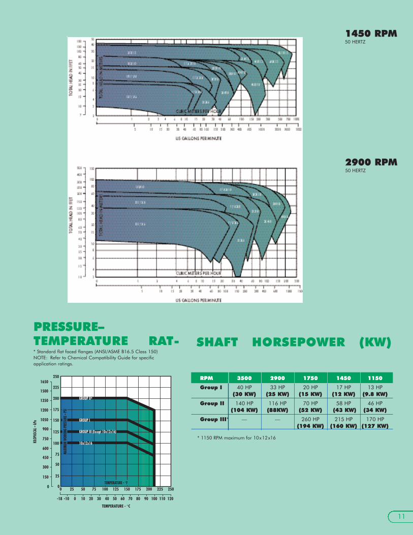
SHAFT HORSEPOWER (KW)PRESSURE–TEMPERATURE RAT-
1450 RPM50 HERTZ
2900 RPM50 HERTZ
750
10 20 30 40 50
TEMPERATURE - °C
60 70 80 90 100 110 120
5025
-10-18 0
100 125 150 175 200 225 250
KILO
PASC
AL –
kPa
TEMPERATURE - °F
GROUP II*
GROUP III (Except 10x12x16)
10x12x16
MAXI
MUM
WORK
ING
PRES
SURE
– PS
I
0
25
50
75
100
125
150
175
200
225
250
0
150
300
450
600
750
900
1050
1200
1350
1500
1650
GROUP I
* Standard flat faced flanges (ANSI/ASME B16.5 Class 150)NOTE: Refer to Chemical Compatibility Guide for specific application ratings.
11
RPM 3500 2900 1750 1450 1150
Group I 40 HP 33 HP 20 HP 17 HP 13 HP(30 KW) (25 KW) (15 KW) (12 KW) (9.8 KW)
Group II 140 HP 116 HP 70 HP 58 HP 46 HP(104 KW) (88KW) (52 KW) (43 KW) (34 KW)
Group III* — — 260 HP 215 HP 170 HP(194 KW) (160 KW) (127 KW)
* 1150 RPM maximum for 10x12x16

PUMP DIMENSIONS FOR SERIES 1500
CP
F
YV
X
D
E1
E2
øH
U
DIMENSIONS SHOWN ARE IN INCHES AND (MILLIMETERS) *CF—Consult Factory (FRP baseplate available up to 365T frame)12
1 x
1.5
x 6
1.5
x 3
x 6
2 x
3 x
6
1 x
1.5
x 8
1.5
x 3
x 8
2 x
3 x
8
3 x
4 x
8
1 x
2 x
10
1.5
x 3
x 10
2 x
3 x
10
3 x
4 x
10
4 x
4 x
10
4 x
6 x
10
2 x
3 x
13
3 x
4 x
13
4 x
6 x
13
6 x
8 x
13
8 x
10 x
15
10 x
12
x 16
PUMP IMPELLERX
SUCTIONX
DISCHARGE
ANSI DESIGNATION AA AB – AA A50 A60 A70 A05 A50 A60 A70 – A80 A30 A40 A80 A90 A120 –
ISO/DIN FLANGE AVAILABILITY – – ✔ – – ✔ ✔ ✔ – ✔ ✔ ✔ ✔ – ✔ ✔ ✔ ✔ ✔
JIS FLANGE AVAILABILITY – – ✔ – – ✔ ✔ ✔ – ✔ ✔ ✔ ✔ – ✔ ✔ ✔ ✔ ✔
CP171/2 231/2 337/8 351/8
(445) (597) (860) (892)
D51/4 81/4 10 141/2 18(133) (210) (254) (368) (457)
X61/2 81/2 91/2 11 81/2 91/2 11 121/2 131/2 111/2 121/2 131/2 16 19 26(165) (216) (242) (280) (216) (242) (280) (318) (343) (292) (318) (343) (406) (483) (660)
F71/4 121/2 183/4 173/4
(184) (318) (476) (541**)
2E16 93/4 16 22
(152) (248) (406) (559)
2E20 71/4 9 14(0) (184) (229) (356)
H5/8 7/8 1(16) (22) (25)
U7/8 11/8 23/8
(22.23) (28.58) (60.33)
KEYWAY3/16 x 3/32 1/4 x 1/8 5/8 x 5/16
(4.76 x 2.38) (6.35 x 3.18) (15.88 x 7.94)
V2 25/8 4
(51) (67) (102)
Y4 6 7
(102) (152) (178)
MOTOR FRAME 143T-184T 143T-145T 254T-365T
BASEPLATE MODEL # 1T 2 5
MOTOR FRAME 213T-215T 182T-286T 404TS-445T*CF
BASEPLATE MODEL # 2T 2 6
MOTOR FRAME 254T-256T 324T-405TS —
BASEPLATE MODEL # 1 3 —
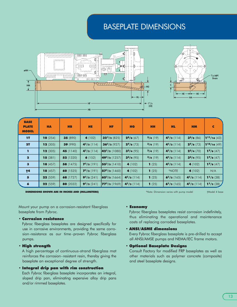
Mount your pump on a corrosion-resistant fiberglassbaseplate from Fybroc.
• Corrosion resistance Fybroc fiberglass baseplates are designed specifically foruse in corrosive environments, providing the same corro-sion-resistance as our time-proven Fybroc fiberglasspumps.
• High strengthA high percentage of continuous-strand fiberglass matreinforces the corrosion-resistant resin, thereby giving thebaseplate an exceptional degree of strength.
• Integral drip pan with rim construction Each Fybroc fiberglass baseplate incorporates an integral,sloped drip pan, eliminating expensive alloy drip pansand/or rimmed baseplates.
• EconomyFybroc fiberglass baseplates resist corrosion indefinitely,thus eliminating the operational and maintenancecosts of replacing corroded baseplates.
• ANSI/ASME dimensionsEvery Fybroc fiberglass baseplate is pre-drilled to acceptall ANSI/AMSE pumps and NEMA/IEC frame motors.
• Optional Baseplate DesignsConsult Factory for modified FRP baseplates as well asother materials such as polymer concrete (composite)and steel baseplate designs.
HE HE
HA
C
3/4 NPT Drain
HG
HB
HF
HL
HM
11/4 (32)
øHH
DIMENSIONS SHOWN ARE IN INCHES AND (MILLIMETERS) *Note: Dimension varies with pump model †Model 4 base
13
BASEPLATE DIMENSIONS
BASEPLATE HA HB HE HF HG HH HL HM CMODEL
1T 10 (254) 35 (890) 4 (102) 321/2 (825) 25/8 (67) 3/4 (19) 41/2 (114) 33/8 (86) 111/16 (43)
2T 12 (305) 39 (990) 41/2 (114) 361/2 (927) 27/8 (73) 3/4 (19) 41/2 (114) 27/8 (73) 115/16 (49)
1 12 (305) 45 (1140) 41/2 (114) 421/2 (1080) 33/4 (95) 3/4 (19) 41/2 (114) 23/4 (70) 17/8 (47)
2 15 (381) 52 (1320) 6 (152) 491/2 (1257) 33/4 (95) 3/4 (19) 41/2 (114) 33/4 (95) 17/8 (47)
3 18 (457) 58 (1475) 71/2 (191) 551/2 (1410) 4 (102) 1 (25) 41/2 (114) 4 (102) 17/8 (47)
†4 18 (457) 60 (1525) 71/2 (191) 571/2 (1460) 4 (102) 1 (25) *NOTE 4 (102) N/A
5 22 (559) 68 (1727) 91/2 (241) 651/2 (1664) 41/2 (114) 1 (25) 61/2 (165) 41/2 (114) 11/2 (38)
6 22 (559) 80 (2032) 91/2 (241) 771/2 (1969) 41/2 (114) 1 (25) 61/2 (165) 41/2 (114) 11/2 (38)

14
OPTIONS DESIGNED TO ELIMINATEALIGNMENT PROBLEMS
CLOSE-COUPLED PUMPS• Capacities to 1500 GPM (345 m3/hr)
• Heads to 400 Ft (125 m)
• C-faced JM extension motors up to 50 HP (37 KW)
• Sixteen sizes (all Fybroc Series 1500 Group I and GroupII pumps)
• Available with all materials of construction (page 2)
• Available for mounting on FRP baseplates
• Lightweight/space efficient design
• Anti-spin-off device (segment key/locking ring) incorpo-rated on the back end of the impeller sleeve to help protect against potential reverse rotation damage.
• Available on all Fybroc Series 1500 Group I and Group II pumps
Group I – motor frame sizes up to 256TCGroup II – motor frame sizes up to 365TSC
• Designed to simplify pump/motor installation and alignment
• Reduces routine maintenance
C-FACE
15
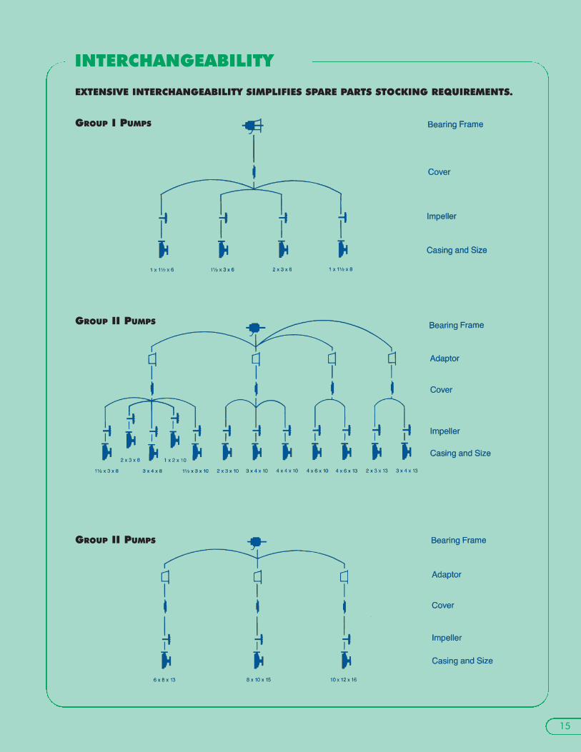
EXTENSIVE INTERCHANGEABILITY SIMPLIFIES SPARE PARTS STOCKING REQUIREMENTS.
GROUP I PUMPS
INTERCHANGEABILITY
GROUP II PUMPS
GROUP II PUMPS

©COPYRIGHT 2004 MET-PRO CORPORATION, FYBROC DIVISION Fybroc Division® IS A REGISTERED TRADEMARK OF MET-PRO CORPORATION 07-5309 604
700 Emlen Way, Telford, PA 18969TOLL-FREE: 1-800-FYBROC-1, Phone: (215) 723-8155, FAX: (215) 723-2197E-Mail: [email protected], Web Site: www.fybroc.com
Fybroc Division
Aqu
atic
Animal Life Support Operations
AALSO
EY-2 EPOXY RESIN (FRP)PUMPS• Identical construction (thermoset) and molding process
(RTM) as pumps manufactured utilizing vinyl ester resin(VR-1)
• Available in all pump configurations: centrifugal(ANSI/ASME dimensioned), close-coupled, self-priming,mag-drive, vertical sump, cantilever
• Excellent corrosion resistance with aggressive, solvent-based chemicals
• Ideal for concentrated sulfuric acid (98%)
• Higher maximum temperature capabilities, in certainapplications, compared to vinyl ester resin (VR-1)
• Typical markets include pharmaceutical, petrochemical,fertilizer, and pesticide. Also, EY-2 allows expandedopportunities for Fybroc pumps in existing markets suchas electronics, chemical process, and metal finishing.