Horizon-Loc - Central States Mfg.€¦ · CENTRAL STATES MANUFACTURING, INC. Effective 2/2018 •...
32
16" COVERAGE 4" 1" ¾" Horizon-Loc ™ Installation Details GUID_INSTL_HLOC_180222 C E Copyright © 2018, Central States Manufacturing, Inc., All Rights Reserved.
Transcript of Horizon-Loc - Central States Mfg.€¦ · CENTRAL STATES MANUFACTURING, INC. Effective 2/2018 •...

16" COVERAGE
4"
1"¾"
Horizon-Loc™
Installation Details
GUID_INSTL_HLOC_180222C E
Copyright © 2018, Central States Manufacturing, Inc., All Rights Reserved.
C E N T R A L S T A T E S M A N U F A C T U R I N G , I N C .E f f e c t i v e 2 / 2 0 1 8 • I n f o r m a t i o n s u b j e c t t o c h a n g e 2
Information in the catalog may vary by plant location.
Please call your salesperson to verify product availability.
Important Information & Safety . . . . . . . . . . . . . . . . . . . . . . . . . . . . . . 3Fastener Spacing. . . . . . . . . . . . . . . . . . . . . . . . . . . . . . . . . . . . . . . . . . . . . 4Tool & Equipment . . . . . . . . . . . . . . . . . . . . . . . . . . . . . . . . . . . . . . . . . . . . 4Concealed Fastener Tools . . . . . . . . . . . . . . . . . . . . . . . . . . . . . . . . . . . . 4Foot Traffic. . . . . . . . . . . . . . . . . . . . . . . . . . . . . . . . . . . . . . . . . . . . . . . . . . . 5Field Cutting . . . . . . . . . . . . . . . . . . . . . . . . . . . . . . . . . . . . . . . . . . . . . . . . . 5Roof Preparation Tips . . . . . . . . . . . . . . . . . . . . . . . . . . . . . . . . . . . . . . . . 5Substrate Penetration . . . . . . . . . . . . . . . . . . . . . . . . . . . . . . . . . . . . . . . 6Substructure Condition . . . . . . . . . . . . . . . . . . . . . . . . . . . . . . . . . . . . . . 6Panel Installation Overview . . . . . . . . . . . . . . . . . . . . . . . . . . . . . . . . . . 7Trim Installation Overview . . . . . . . . . . . . . . . . . . . . . . . . . . . . . . . . . . . 7Panel Installation. . . . . . . . . . . . . . . . . . . . . . . . . . . . . . . . . . . . . . . . . . . . . 8Eave Termination. . . . . . . . . . . . . . . . . . . . . . . . . . . . . . . . . . . . . . . . . . . . . 9Concealed Fastener Conditions . . . . . . . . . . . . . . . . . . . . . . . . . . . . . . 10-23 Drip Edge Trim . . . . . . . . . . . . . . . . . . . . . . . . . . . . . . . . . . . . . . . . . 10-11 Rake Trim. . . . . . . . . . . . . . . . . . . . . . . . . . . . . . . . . . . . . . . . . . . . . . . 12-13 Sidewall Trim . . . . . . . . . . . . . . . . . . . . . . . . . . . . . . . . . . . . . . . . . . . 14-15 Endwall Trim . . . . . . . . . . . . . . . . . . . . . . . . . . . . . . . . . . . . . . . . . . . 16-17 Valley Trim. . . . . . . . . . . . . . . . . . . . . . . . . . . . . . . . . . . . . . . . . . . . . . 18-19 Transition Trim . . . . . . . . . . . . . . . . . . . . . . . . . . . . . . . . . . . . . . . . . 20-21 Ridgecap Trim . . . . . . . . . . . . . . . . . . . . . . . . . . . . . . . . . . . . . . . . . . 22-23Exposed Fastener Conditions. . . . . . . . . . . . . . . . . . . . . . . . . . . . . . . . . 24-31 Eave Trim. . . . . . . . . . . . . . . . . . . . . . . . . . . . . . . . . . . . . . . . . . . . . . . 24-25 Rake Trim. . . . . . . . . . . . . . . . . . . . . . . . . . . . . . . . . . . . . . . . . . . . . . . 26-27 Ridge/Hip Trim . . . . . . . . . . . . . . . . . . . . . . . . . . . . . . . . . . . . . . . . . 28-29 Valley Trim. . . . . . . . . . . . . . . . . . . . . . . . . . . . . . . . . . . . . . . . . . . . . . 30-31
INDEX

C E N T R A L S T A T E S M A N U F A C T U R I N G , I N C .E f f e c t i v e 2 / 2 0 1 8 • I n f o r m a t i o n s u b j e c t t o c h a n g e 3
This manual contains suggestions and guidelines on how to install Horizon-Loc panels. The drawings in this guide are for illustration purposes only and may not apply to all building designs or product applications. The installation details shown are proven methods of construction, but are not intended to cover all instances, building requirements, designs, or codes. It is the responsibility of the designer/installer to ensure that the details meet particular building requirements. The designer/installer must be aware of, and allow for, expansion/contraction of roof panels. The details may require changes or revisions due to each project’s conditions.
There are certain minimum live, snow, dead, collateral, and wind loads that a roof must generally be designed to support. Consult local building officials to determine the appropriate building design load requirements. A professional engineer should be consulted for all roof system designs. It is the buyer’s responsibility to verify all applicable
code requirements, check all measurements, and determine suitability of product for the job. The buyer is also responsible for determining lengths and quantities needed. Prior to ordering and installing materials, all dimensions should be verified with field measurements. Implied warranties of merchantability and fitness for a particular purpose are disclaimed. All Horizon-Loc instructions assume that a qualified firm or individual has been contacted regarding application of this product. Failure to comply with stated recommendations relieves the manufacturer of responsibility for any damage or deterioration of the product incurred and voids any applicable warranty.
Central States Manufacturing reserves the right to modify, without notice, information in this guide. If you have questions regarding proper installation of Horizon-Loc or information not included in this guide, contact your salesperson.
SAFETY
Always wear heavy gloves when working with steel panels to avoid cuts from sharp edges. When power cutting or drilling steel panels, always wear safety glasses to prevent eye injury from flying metal fragments.
CAUTION
Each job site presents different hazards; therefore it is the responsibility of the buyer/installer to determine the safest way to install the Horizon-Loc roof panel system based on the recommended instructions contained in this guide. Provide crew members working on the roof with required safety railing, netting or safety lines. If you must walk on a metal roof, take great care. Metal panels can become slippery, so always wear shoes with non-slip soles. Avoid working on metal roofs during wet
conditions when the panels can become extremely slippery. Walking or standing on a metal roof which does not have a plywood or other deck beneath it is not recommended. However, if you must do so, always walk on the purlins, never between. Horizon-Loc is designed to be installed over solid plywood decking.
OSHA safety regulations should be complied with at all times.
IMPORTANT INFORMATION

C E N T R A L S T A T E S M A N U F A C T U R I N G , I N C .E f f e c t i v e 2 / 2 0 1 8 • I n f o r m a t i o n s u b j e c t t o c h a n g e 4
Maximum fastener spacing* for 16" wide 26 gauge panels with wind loads up to 80 mph:
*Slot on leg may not coincide with above chart.
DECK THICKNESS SPACING
1/2" .........................................................18" o.c.
5/8" .........................................................21" o.c.
3/4" .........................................................24" o.c.
• Snips• Tape Measure• Electric Metal Shear*• Caulking Gun• Cordless Drill• Blind Rivet Tool• Chalk Line• 6" Hand Seamer• Hemming/Folding Tool• Gloves• Notcher
*We do not recommend the use of a power circular saw to cut panels. Use of a power saw could:
• Increase the instance of edge rust. • Cause hot metal shavings on panel surface
to damage panel finish.
We recommend that the installer have prior experience and knowledge of the listed tools and their uses in working with metal roofing.
FASTENER SPACING
TOOLS & EQUIPMENT
CONCEALED FASTENER TOOLS
Hand Snips Notcher Rivet Hole Punch
Hand Riveter Folding Tools
6" Hand Seamer
To follow UL580 testing for a Class 90 rating, fasteners should be spaced at 4.9" on center.
TIP

C E N T R A L S T A T E S M A N U F A C T U R I N G , I N C .E f f e c t i v e 2 / 2 0 1 8 • I n f o r m a t i o n s u b j e c t t o c h a n g e 5
Care of metal panels and flashings must be exercised throughout installation. Foot traffic can cause distortion of panel and damage to finish. Traffic over the installed system must be kept to an absolute minimum. If continuous foot traffic is necessary for maintenance over certain areas of the roof, then a permanent walkway should be installed. If continuous foot traffic is necessary
during installation, provide walking platforms to avoid any panel damage, or leave panels off where there is easiest access to roof until projects is almost complete. Then install panels in this area.
When walking on the roof panels is unavoidable, walk only in the flats of the panel. Walking on the ribs can cause damage to the panels.
There are a number of ways to cut sheet metal quickly and accurately. Tin snips or a “nibbler” type electric tool are recommended for field cutting Horizon-Loc panels. Cutting over a trash barrel will help catch the tiny metal shavings that the machine produces.
Although Central States discourages it, if a power saw is used, the blade will generate slivers of metal chips. These slivers and metal chips must be
immediately removed from the Horizon-Loc panels because they will damage the finish and shorten the life of the product. One method of preventing this problem is to flip the panels over when cutting. This allows the slivers and metal chips to be brushed from the back side and avoids damaging the paint on the top side of the panels. Make sure that stacks of panels are away from the cutting area so shavings do not blow onto other panels.
• Horizon-Loc is designed to be installed over solid decking. We recommend a minimum 1/2" plywood sheathing
• Make sure any existing decking is smooth, level and in good condition. Replace any decking not meeting those requirements.
• If there is an existing asphalt shingle roof it must be removed.
• Make sure the roof is clear of any debris that might interfere with installation.
• Use minimum 30 lb. felt or synthetic underlayment.
• Use an alignment or “chalk” line where the first panel is installed. Central States recommends that this line be vertical and 1/4" from the rake edge of the roof deck and square with the eave. Other methods of confirming the squareness can also be used.
All applicable safety regulations, including OSHA regulations, should be complied with during the panel installation process. CAUTION
All product surfaces should be free of debris at all times. Installed surfaces should be wiped clean at the end of each work period. Never cut panels over metal surfaces. When cutting metal panels, always wear heavy gloves to avoid cuts from sharp edges and safety glasses to prevent eye injury. CAUTION
FOOT TRAFFIC
FIELD CUTTING
ROOF PREPARATIONS TIPS
Shavings created by saw cutting or drilling may cause the panel to rustand will void warranties in affected areas.

C E N T R A L S T A T E S M A N U F A C T U R I N G , I N C .E f f e c t i v e 2 / 2 0 1 8 • I n f o r m a t i o n s u b j e c t t o c h a n g e 6
SUBSTRATE PENETRATION
SUBSTRUCTURE CONDITION
In warm weather and tropical climates, red rosin paper should be applied over the felt paper to prevent the felt paper from sticking to the panels and tearing the vapor retarder. The red rosin paper will allow for better thermal expansion. In cold
weather climates, it is recommended that you use an ice and water shield at the valley and eave. This needs to be applied over the substrate before the underlayment is installed.
NOTE: This chart to be used as a quoting guide only. Central States Manufacturing recommends field measuring all lengths before placing order.
SLOPE SLOPEFACTOR
HIP/VALLEYMULTIPLIER
SLOPE SLOPEFACTOR
HIP/VALLEYMULTIPLIER
6:12 1.1180 1.5000 12:12 1.4142 1.73205:12 1.0833 1.4743 11:12 1.3566 1.68534:12 1.0541 1.4530 10:12 1.3017 1.64153:12 1.0308 1.4362 9:12 1.2500 1.6008
ROOF SLOPE FACTOR CHART
(L) x (Hip Valley Multiplier) = H (F) x (Slope Factor) = S(L) x (Hip Valley Multiplier) = H (F) x (Slope Factor) = S
SLOPE SLOPE HIP/VALLEY SLOPE SLOPE HIP/VALLEY FACTOR MULTIPLIER FACTOR MULTIPLIER
3:12 1.0308 1.4362 9:12 1.2500 1.6008 4:12 1.0541 1.4530 10:12 1.3017 1.6415 5:12 1.0833 1.4743 11:12 1.3566 1.6853 6:12 1.1180 1.5000 12:12 1.4142 1.7320
ROOF SLOPE FACTOR CHART
NOTE: This chart to be used as a quoting guide only. Central States Manufacturing recommends field measuring all lengths before placing an order.
Panel distortion may occur if not applied over properly aligned and uniform substructure.
The installer should check the roof deck for squareness before installing Horizon-Loc panels. Several methods can be used to verify squareness of the structure for proper installation of the panels.
Method A – One method for checking the roof for squareness is to measure diagonally across one slope of the roof from similar points at the ridge and eave and obtain the same dimension.
Method B – The 3-4-5 triangle system may also be used. To use this system, measure a point from the corner along the edge of the roof at a module of three (3). Measure a point from the same corner along another edge at a module of four (4). Then,
by measuring diagonally between the two points established, the dimension should be exactly a module of five (5) to have a square corner. Multiple uses of this system may be required to determine building squareness. If the endwall cannot be made square the roof system cannot be installed as shown in these instructions.
C E N T R A L S T A T E S M A N U F A C T U R I N G , I N C .E f f e c t i v e 2 / 2 0 1 8 • I n f o r m a t i o n s u b j e c t t o c h a n g e 7
Familiarize yourself with all installation instructions before starting work. Before beginning installation, you should examine the substrate or framing to ensure that all supporting members are straight, level, and plumb to avoid any panel distortion. Substructures should be designed to meet all necessary code requirements.
Some field cutting and fitting of panels and trims is to be expected by the installer and minor field corrections are a part of normal installation work.
It is the responsibility of the installer to ensure a suitable substrate prior to the application of Horizon-Loc. Underlayment must be nailed or stapled down. Distortion in the panel caused by an uneven substrate, ripples, or laps in the vapor barrier, debris, protruding nails and staples,button cap nails, etc., are not defects in the materials and are not the responsibility of Central States Manufacturing.
All trims, closures, and accessories shown on the installation drawings are available from Central States Manufacturing unless noted otherwise.
Oil canning in the flat area of the panels is common to the industry and does not affect the integrity of the panel. Therefore, oil canning is not a reason for rejection.
The panels should be installed plumb, straight, and square to the eave. To keep the bottom edge of the roof perfectly straight and even, the panels must be installed square to the bottom edge. Begin by checking the roof for square; if it is square, you may pull the layout marks directly from the edge of the rake.
If the roof isn’t perfectly square, install the first panel parallel to your square line, making sure that the first rib does not hang over the gable edge of the roof sheathing. (Any overhang can prevent the gable trim from fitting tight against the rake.)
NOTE: Copper metallic panels must be installed in the same direction! See directional arrows or stickers provided with your metal panel order.
On runs of more than 10' 2" that require more than one length of trim, overlap the pieces by 2". The material is thin enough that the overlaps are not noticeable. Trim is attached with rivets or gasketed screws; take care to drive the screws enough to flatten the neoprene washer but not enough to deflect the roofing or the trim.
The tricky part is finishing the ends of each trim run. It may take a bit more time, but cutting and folding the ends of the trim will give the roof a more finished look.
When hooking the hem, measure over on hem 3" from end of trim piece. Cut hem 1/8" up from the bend to 3" mark. Cut off back of hem. On lap piece, open up hem with screwdriver. Insert piece. Slide together. Use rivets and sealant on lap where needed.
PANEL INSTALLATION OVERVIEW
TRIM INSTALLATION OVERVIEW
Remove strippable film from panels and trims before installation.
TIP

C E N T R A L S T A T E S M A N U F A C T U R I N G , I N C .E f f e c t i v e 2 / 2 0 1 8 • I n f o r m a t i o n s u b j e c t t o c h a n g e 8
PANEL INSTALLATION1. Align the female edge of the first panel with the
chalk line that was snapped at the rake edge. This line can be 0" – 1 3/4" from the rake. Panel should overhang eave 1". See Figure 1.
2. Panels should be installed perpendicular to ridge for ridge trim attachment. Check panel alignment. If panel is properly aligned proceed to step 3.
3. Attach rake edge to roof with a 1" painted neoprene metal to wood fastener spaced at 48" on center. Then fasten the panel along the male edge fastening flange with 1" low profile pancake head. Special care has to be taken not to overdrive the screws in the male edge fastening flange. The screw flange is slotted to allow for slight panel movement during normal expansion and contraction. To avoid panel distortion and to allow for maximum expansion and contraction of the panel, the screws should be snugged against the flange, but not so snug that the flange deflects under the screw head. To allow for movement of the panel towards the eave or ridge, place the fastener in the middle of the 5/8" slot. See fastener spacing on page 4.
4. Align the second panel female edge with the starter panel male edge. See Figure 2. Panels must be flush to one another. Remember, panels should extend over eave trim by 1".
5. Lightly compress and snap panels together at seam. Snap panels from eave to ridge. Screw the second panel in place using 1" low profile pancake head screw in the male edge fastening flange.
6. Continue to apply panels as in steps 4 and 5.
7. Panels at the eave can be terminated in two ways, with fasteners or without. Each will depend on aesthetic consideration determined by the installer or building owner.
FIGURE 1
C E N T R A L S T A T E S M A N U F A C T U R I N G , I N C .E f f e c t i v e 2 / 2 0 1 8 • I n f o r m a t i o n s u b j e c t t o c h a n g e 9
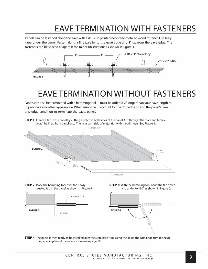
Panels can be fastened along the eave with a #10 x 1" painted neoprene metal to wood fastener. Use butyl tape under the panel. Fasten along a line parallel to the eave edge and 3" up from the eave edge. The fasteners can be spaced 4" apart in the minor rib striations as shown in Figure 3.
FIGURE 3
HORIZON-LOC™
HORIZON-LOC™
HORIZON-LOC™
HORIZON-LOC™
HORIZON-LOC™
HORIZON-LOC™
Panels can also be terminated with a hemming tool to provide a smoother appearance. When using the drip edge condition to terminate the eave, panels
must be ordered 2" longer than your eave length to account for the drip edge lip and the panel’s hem.
STEP 1: Create a tab in the panel by cutting a notch in both sides of the panel. Cut through the male and female legs/ribs 1" up from panel end. Then cut on inside of major ribs with metal shears. See Figure 4.
STEP 2: Place the hemming tool over the newly created tab in the panel as shown in Figure 5.
STEP 3: With the hemming tool bend the tab down and under to 180° as shown in Figure 6.
FIGURE 4
FIGURE 5 FIGURE 6
STEP 4: The panel is then ready to be installed over the Drip Edge trim, using the lip on the Drip Edge trim to secure the panel in place at the eave as shown on page 10.
EAVE TERMINATION WITH FASTENERS
EAVE TERMINATION WITHOUT FASTENERS
butyl tape

C E N T R A L S T A T E S M A N U F A C T U R I N G , I N C .E f f e c t i v e 2 / 2 0 1 8 • I n f o r m a t i o n s u b j e c t t o c h a n g e 10
REQUIRED TRIMS:
DRIP EDGE TRIM CONDITION
CONCEALED FASTENER
DRIP EDGE - HLRDC
REQUIRED TRIMS:
/////////////////////////////////////////
When ordering Horizon-Loc panels, be sure to add an extra 2" to the length for hemming over the drip edge. (One inch covers the drip edge and one inch is hemmed under).
HORIZON-LOC™
HORIZON-LOC™
TIP
Painted side

C E N T R A L S T A T E S M A N U F A C T U R I N G , I N C .E f f e c t i v e 2 / 2 0 1 8 • I n f o r m a t i o n s u b j e c t t o c h a n g e 11
///////////////////////////////////////// /////////////////////////////////////////
1. Screw the drip edge to the decking.
2. Notch the Horizon-Loc panels at the rib (1 inch from the end of the panel).
3. Using the Horizon-Loc folding tool, fold the panel at the notching so that the unpainted sides of the panel are facing each other.
4. Slide panel over drip edge, snap in panel, and screw into decking.
5. Repeat steps 2-4 for each Horizon-Loc panel along the drip edge.
6. Seal end thoroughly as in Figure 1, or leave tab when notching and fold over end for a more finished look as in Figure 2.
DRIP EDGE TRIM CONDITION
DIRECTIONS:
CONCEALED FASTENER
HORIZON-LOC™
HORIZON-LOC™
NOTE: See page 31 for detailed information on eave termination without fasteners
See page 24 for exposed fastener condition
FIGURE 1. FIGURE 2.

C E N T R A L S T A T E S M A N U F A C T U R I N G , I N C .E f f e c t i v e 2 / 2 0 1 8 • I n f o r m a t i o n s u b j e c t t o c h a n g e 12
REQUIRED TRIMS:
BUTYL TAPE(CONTINUOUS)
HORIZON-LOC™
POP RIVET(2’ O.C.)
BUTYL TAPE(CONTINUOUS)
HORIZON-LOC™
POP RIVET(2’ O.C.)
RAKE TRIM CONDITION
CONCEALED FASTENER
Painted side
ZEE CLOSURE - HLZC
Painted side
OPEN HEM RAKE - CFRA
REQUIRED TRIMS:
/////////////////////////////////////////
See page 26 for exposed fastener condition
Painted side
CLEAT - HLCL

C E N T R A L S T A T E S M A N U F A C T U R I N G , I N C .E f f e c t i v e 2 / 2 0 1 8 • I n f o r m a t i o n s u b j e c t t o c h a n g e 13
/////////////////////////////////////////
BUTYL TAPE(CONTINUOUS)
HORIZON-LOC™
POP RIVET(2’ O.C.)
BUTYL TAPE(CONTINUOUS)
HORIZON-LOC™
POP RIVET(2’ O.C.)
1. Install the cleat along the rake of the roof and install Horizon-Loc panel on top of the cleat. The edge of the panel should meet with the edge of the rake.
2. Install zee closure on top of the panel. Use butyl tape beneath to ensure proper sealing. Run the zee along the length of the rake and screw down to the panel.
3. Install the rake trim to the cleat and zee closure by snapping the open hems of the rake trim over the cleat and zee. Pop rivet the rake to the zee along the joints and every 5 feet along the rake. Overlap trims a minimum of 2" with butyl tape between laps.
RAKE TRIM CONDITION
DIRECTIONS:
///////////////////////////////////////// CONCEALED FASTENER
C E N T R A L S T A T E S M A N U F A C T U R I N G , I N C .E f f e c t i v e 2 / 2 0 1 8 • I n f o r m a t i o n s u b j e c t t o c h a n g e 14
REQUIRED TRIMS:
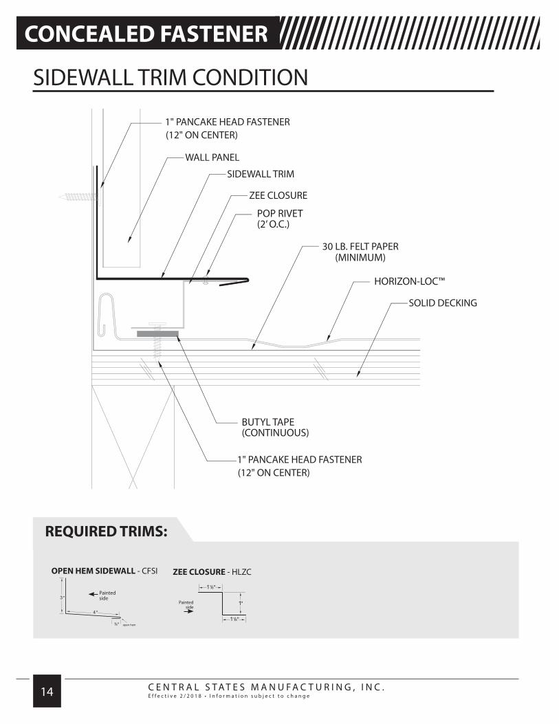
SIDEWALL TRIM CONDITION
CONCEALED FASTENER
ZEE CLOSURE - HLZC
Painted side
OPEN HEM SIDEWALL - CFSI
REQUIRED TRIMS:
/////////////////////////////////////////
BUTYL TAPE(CONTINUOUS)
POP RIVET(2’ O.C.)
HORIZON-LOC™
HORIZON-LOC™
BUTYL TAPE(CONTINUOUS)
POP RIVET(2’ O.C.)
Painted side

C E N T R A L S T A T E S M A N U F A C T U R I N G , I N C .E f f e c t i v e 2 / 2 0 1 8 • I n f o r m a t i o n s u b j e c t t o c h a n g e 15
///////////////////////////////////////// /////////////////////////////////////////
1. Install Horizon-Loc panels up to the sidewall. Install zee closure on top of the panel along the sidewall using butyl tape to ensure proper sealing.
2. Slide the open hem of the sidewall trim over the zee and screw into sidewall. Pop rivet the sidewall trim to the zee closure.
3. Repeat steps 1 and 2 for each panel along the sidewall.
4. Install Horizon-Loc panels over the sidewall. Overlap trims a minimum of 2" with butyl tape between laps.
SIDEWALL TRIM CONDITION
DIRECTIONS:
CONCEALED FASTENER
BUTYL TAPE(CONTINUOUS)
POP RIVET(2’ O.C.)
HORIZON-LOC™
HORIZON-LOC™
BUTYL TAPE(CONTINUOUS)
POP RIVET(2’ O.C.)

C E N T R A L S T A T E S M A N U F A C T U R I N G , I N C .E f f e c t i v e 2 / 2 0 1 8 • I n f o r m a t i o n s u b j e c t t o c h a n g e 16
REQUIRED TRIMS:
ENDWALL TRIM CONDITION
CONCEALED FASTENER
ZEE CLOSURE - HLZC
Painted side
OPEN HEM ENDWALL - CFSI
REQUIRED TRIMS:
/////////////////////////////////////////
Painted side
BUTYL TAPE(CONTINUOUS)
POP RIVET(2’ O.C.)
HORIZON-LOC™
BUTYL TAPE(CONTINUOUS)
POP RIVET(2’ O.C.)
HORIZON-LOC™

C E N T R A L S T A T E S M A N U F A C T U R I N G , I N C .E f f e c t i v e 2 / 2 0 1 8 • I n f o r m a t i o n s u b j e c t t o c h a n g e 17
///////////////////////////////////////// /////////////////////////////////////////
1. Install Horizon-Loc panels up to the endwall. Install zee closure on top of the panel along the endwall using butyl tape to ensure proper sealing. Zee closures will need to be cut in 15-1/2" lengths and screwed to the panel. Use a drill at high rpm to avoid damaging butyl tape seal when fastening screws. Seal cut edge of zee closure with tube sealant.
2. Slide the open hem of the endwall trim over the zee and screw into endwall. Overlap trims a minimum of 2" with butyl tape between laps. Pop rivet the endwall trim to the zee closure.
3. Repeat steps 1 and 2 for each panel along the endwall.
4. Install wall panels over the endwall.
ENDWALL TRIM CONDITION
DIRECTIONS:
CONCEALED FASTENER
BUTYL TAPE(CONTINUOUS)
POP RIVET(2’ O.C.)
HORIZON-LOC™
BUTYL TAPE(CONTINUOUS)
POP RIVET(2’ O.C.)
HORIZON-LOC™
C E N T R A L S T A T E S M A N U F A C T U R I N G , I N C .E f f e c t i v e 2 / 2 0 1 8 • I n f o r m a t i o n s u b j e c t t o c h a n g e 18
REQUIRED TRIMS:
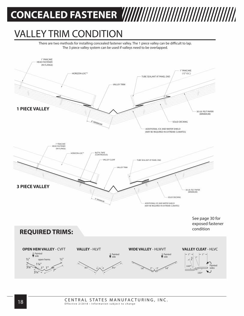
VALLEY TRIM CONDITION
CONCEALED FASTENER
OPEN HEM VALLEY - CVFT
REQUIRED TRIMS:
/////////////////////////////////////////
See page 30 for exposed fastener condition
HORIZON-LOC™
Painted side
VALLEY CLEAT - HLVC
VALLEY CLEAT
BUTYL TAPE(CONTINUOUS)
HORIZON-LOC™
1 PIECE VALLEY
3 PIECE VALLEY
14" 14"1" 1"
VALLEY - HLVTPainted side
WIDE VALLEY - HLWVTPainted side
Painted sides
There are two methods for installing concealed fastener valley. The 1 piece valley can be difficult to lap. The 3 piece valley system can be used if valleys need to be overlapped.

C E N T R A L S T A T E S M A N U F A C T U R I N G , I N C .E f f e c t i v e 2 / 2 0 1 8 • I n f o r m a t i o n s u b j e c t t o c h a n g e 19
///////////////////////////////////////// /////////////////////////////////////////
1. Using the folding tool, hem the end of the valley 1 inch and slide over drip edge (if drip edge is being used).
2. Install valley to decking, placing screws as far up as possible on the 3-1/8" section of the valley.
3. Hem the panel at a 45° angle (or according to the valley pitch) where it meets the valley and slide under the open hem on the valley.
4. Slide panel over valley, snap in panel, and screw into decking.
5. Repeat step 3 for each panel as it meets the valley. Overlap trims a minimum of 6" with butyl tape between laps.
6. Use tube sealant at panel end.
VALLEY TRIM CONDITION
DIRECTIONS:
CONCEALED FASTENER
1” METAL TO WOOD FASTENER(4 PER PANEL)
1” METAL TO WOOD FASTENER(4 PER PANEL)
BUTYL TAPE(CONTINUOUS)
HORIZON-LOC™
BUTYL TAPE(CONTINUOUS)
HORIZON-LOC™(MITER CUT TO MATCH SLOPE)
MITER CUTTO MATCH
SLOPE
HORIZON-LOC™
TYPICAL PANEL END SEAL

C E N T R A L S T A T E S M A N U F A C T U R I N G , I N C .E f f e c t i v e 2 / 2 0 1 8 • I n f o r m a t i o n s u b j e c t t o c h a n g e 20
REQUIRED TRIMS:
TRANSITION TRIM CONDITION
CONCEALED FASTENER
ZEE CLOSURE - HLZC
Painted side
OPEN HEM GAMBREL - CFGA
REQUIRED TRIMS:
/////////////////////////////////////////
BUTYL TAPE(CONTINUOUS)
POP RIVET(2’ O.C.)
HORIZON-LOC™
HORIZON-LOC™
BUTYL TAPE(CONTINUOUS)
HORIZON-LOC™
HORIZON-LOC™
Painted side

C E N T R A L S T A T E S M A N U F A C T U R I N G , I N C .E f f e c t i v e 2 / 2 0 1 8 • I n f o r m a t i o n s u b j e c t t o c h a n g e 21
///////////////////////////////////////// /////////////////////////////////////////
1. Install the bottom Horizon-Loc panels and attach zee closures. Zee closures will need to be cut in 15-1/2" lengths and screwed to the panel. Use butyl tape to ensure proper sealing. Seal cut edge of zee closure with tube sealant.
2. Slide the open hem of gambrel trim over zee, and screw gambrel to upper decking. Overlap trims a minimum of 2" with butyl tape between laps.
3. Notch and hem panel 1" and slide over open hem on gambrel trim. Screw panel to decking.
4. Pop rivet trim to zee on lower portion of the trim.
5. Repeat steps 1 through 3 for each panel along the transition.
TRANSITION TRIM CONDITION
DIRECTIONS:
CONCEALED FASTENER
BUTYL TAPE(CONTINUOUS)
POP RIVET(2’ O.C.)
HORIZON-LOC™
HORIZON-LOC™
BUTYL TAPE(CONTINUOUS)
HORIZON-LOC™
HORIZON-LOC™

C E N T R A L S T A T E S M A N U F A C T U R I N G , I N C .E f f e c t i v e 2 / 2 0 1 8 • I n f o r m a t i o n s u b j e c t t o c h a n g e 22
ZEE CLOSURE - HLZC
Painted side
OPEN HEM RIDGECAP CFRC
REQUIRED TRIMS:
RIDGECAP TRIM CONDITION
CONCEALED FASTENER
REQUIRED TRIMS:
/////////////////////////////////////////
See page 28 for exposed fastener condition
POP RIVET(2’ O.C.)
POP RIVET(2’ O.C.)
BUTYL TAPE(CONTINUOUS)
1” METAL TO WOOD FASTENER(2 PER PANEL)
HORIZON-LOC™
HORIZON-LOC™
BUTYL TAPE(CONTINUOUS)
1” METAL TO WOOD FASTENER(2 PER PANEL)
Painted side
Painted side
OPEN HEM WIDE RIDGECAPCFWRC Painted
side
OPEN HEM FLAT RIDGECFFRC

C E N T R A L S T A T E S M A N U F A C T U R I N G , I N C .E f f e c t i v e 2 / 2 0 1 8 • I n f o r m a t i o n s u b j e c t t o c h a n g e 23
///////////////////////////////////////// /////////////////////////////////////////
1. Install panels on both sides of roof up to the ridge, and install zee closures. Zee closures will need to be cut in 15-1/2" lengths and screwed to the panel. Use butyl tape to ensure proper sealing. Seal cut edge of zee closure with tube sealant. When venting, leave a gap for air flow at ridge.
2. Snap ridgecap over zee closures and pop rivet to the zee every 2’ and at joints.
RIDGE CAP TRIM CONDITION
DIRECTIONS:
CONCEALED FASTENER
POP RIVET(2’ O.C.)
POP RIVET(2’ O.C.)
BUTYL TAPE(CONTINUOUS)
1” METAL TO WOOD FASTENER(2 PER PANEL)
HORIZON-LOC™
HORIZON-LOC™
BUTYL TAPE(CONTINUOUS)
1” METAL TO WOOD FASTENER(2 PER PANEL)
When overlapping ridgecap, cut 6" off bottom hem of the underlapping ridgecap and slide upper ridgecap over. Pop rivet with sealant on each lap. Overlap trims a minimum of 6" with butyl tape or sealant between laps.

C E N T R A L S T A T E S M A N U F A C T U R I N G , I N C .E f f e c t i v e 2 / 2 0 1 8 • I n f o r m a t i o n s u b j e c t t o c h a n g e 24
BUTYL TAPE(CONTINUOUS)
1” METAL TO WOOD FASTENER(12” O.C.)
HORIZON-LOC™
1” METAL TO WOOD FASTENER(2 PER PANEL)
EAVE TRIM CONDITION
REQUIRED TRIMS:
See page 10for concealed fastener condition
EAVE TRIM - HLRE
EXPOSED FASTENER /////////////////////////////////////////
Painted side

C E N T R A L S T A T E S M A N U F A C T U R I N G , I N C .E f f e c t i v e 2 / 2 0 1 8 • I n f o r m a t i o n s u b j e c t t o c h a n g e 25
1. Attach eave trim as shown with #10 x 1" low profile pancake fastener.
2. For multiple low eave trim applications, open the hem of the underlap trim 4" and cut off the hem. On the overlapping eave trim, open the bottom hem 4". Apply sealant onto the underlapping eave trim and slide the overlapping eave trim into place.
3. Install panel and fasten at eave with #10 x 1" Metal to Wood fastener.
Additional ice and water shields maybe required if climate is extreme.
EAVE TRIM CONDITION
DIRECTIONS:NOTE: Eave trim must be installed prior to panel installation. Also, panel should overhang the eave 1" minimum.
////////////////////////////////////////////////////////////////////////////////// EXPOSED FASTENER
BUTYL TAPE(CONTINUOUS)
1” METAL TO WOOD FASTENER(12” O.C.)
HORIZON-LOC™
1” METAL TO WOOD FASTENER(2 PER PANEL)
TYPICAL PANEL END SEAL

C E N T R A L S T A T E S M A N U F A C T U R I N G , I N C .E f f e c t i v e 2 / 2 0 1 8 • I n f o r m a t i o n s u b j e c t t o c h a n g e 26
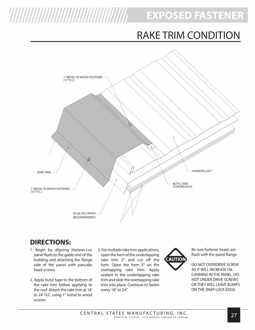
RAKE TRIM CONDITION
REQUIRED TRIMS:
See page 12for concealed fastener condition
RAKE TRIM - HLRRT
EXPOSED FASTENER /////////////////////////////////////////
BUTYL TAPE(CONTINUOUS)
HORIZON-LOC™
HORIZON-LOC™
BUTYL TAPE(CONTINUOUS)
1” METAL TO WOOD FASTENER(12” O.C.)
1” METAL TO WOOD FASTENER(12” O.C.)
1” METAL TO WOODFASTENER
(12” O.C.)
1” METAL TO WOOD FASTENER(12” O.C.)
Painted side
C E N T R A L S T A T E S M A N U F A C T U R I N G , I N C .E f f e c t i v e 2 / 2 0 1 8 • I n f o r m a t i o n s u b j e c t t o c h a n g e 27
/////////////////////////////////////////
1. Begin by aligning Horizon-Loc panel flush to the gable end of the building and attaching the flange side of the panel with pancake head screws.
2. Apply butyl tape to the bottom of the rake trim before applying to the roof. Attach the rake trim at 18' to 24' O.C. using 1" metal to wood screws.
3. For multiple rake trim applications, open the hem of the underlapping rake trim 2" and cut off the hem. Open the hem 3" on the overlapping rake trim. Apply sealant to the underlapping rake trim and slide the overlapping rake trim into place. Continue to fasten every 18" to 24".
RAKE TRIM CONDITION
DIRECTIONS:
///////////////////////////////////////// EXPOSED FASTENER
BUTYL TAPE(CONTINUOUS)
HORIZON-LOC™
HORIZON-LOC™
BUTYL TAPE(CONTINUOUS)
1” METAL TO WOOD FASTENER(12” O.C.)
1” METAL TO WOOD FASTENER(12” O.C.)
1” METAL TO WOODFASTENER
(12” O.C.)
1” METAL TO WOOD FASTENER(12” O.C.)
Be sure fastener heads are flush with the panel flange.
DO NOT OVERDRIVE SCREW AS IT WILL INCREASE OIL CANNING IN THE PANEL. DO NOT UNDER DRIVE SCREWS OR THEY WILL LEAVE BUMPS ON THE SNAP LOCK EDGE.
CAUTION

C E N T R A L S T A T E S M A N U F A C T U R I N G , I N C .E f f e c t i v e 2 / 2 0 1 8 • I n f o r m a t i o n s u b j e c t t o c h a n g e 28
RIDGE/HIP TRIM CONDITION
ZEE CLOSURE - HLZC
Painted side
REQUIRED TRIMS:
See page 22for concealed fastener condition
1” METAL TO WOOD FASTENER(2 PER PANEL)
BUTYL TAPE(CONTINUOUS)
HORIZON-LOC™
BUTYL TAPE(CONTINUOUS)
BUTYL TAPE(CONTINUOUS)
BUTYL TAPE(CONTINUOUS)
1” METAL TO WOOD FASTENER(2 PER PANEL)
HORIZON-LOC™
RIDGECAP - HLRHPainted side
RESIDENTIAL RIDGECAP - RRCPPainted side
HIP CAP - HIPPainted side
EXPOSED FASTENER /////////////////////////////////////////

C E N T R A L S T A T E S M A N U F A C T U R I N G , I N C .E f f e c t i v e 2 / 2 0 1 8 • I n f o r m a t i o n s u b j e c t t o c h a n g e 29
/////////////////////////////////////////
1. Panels must be field cut at hip. Panels should end parallel to the ridge.
2. Zee closures will need to be cut to fit and screwed to the panel. Attach zee closure parallel to closure ridge. Seal cut edge of zee closure with tube sealant.
3. Fasten hip/ridge trim to the zee using #14 x 7/8" Lap/screw. Use a drill at high rpm to avoid damaging butyl tape seal when fastening screws. Caulk, lap (minimum of 6" hooking the hem) and fasten the subsequent trims.
RIDGE/HIP TRIM CONDITION
DIRECTIONS:
1” METAL TO WOOD FASTENER(2 PER PANEL)
BUTYL TAPE(CONTINUOUS)
HORIZON-LOC™
BUTYL TAPE(CONTINUOUS)
BUTYL TAPE(CONTINUOUS)
BUTYL TAPE(CONTINUOUS)
1” METAL TO WOOD FASTENER(2 PER PANEL)
HORIZON-LOC™
NOTE: Rake trim must be installed prior to installing the ridge or hip.
///////////////////////////////////////// EXPOSED FASTENER

C E N T R A L S T A T E S M A N U F A C T U R I N G , I N C .E f f e c t i v e 2 / 2 0 1 8 • I n f o r m a t i o n s u b j e c t t o c h a n g e 30
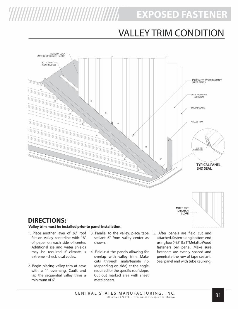
VALLEY TRIM CONDITION
REQUIRED TRIMS:
See page 18for concealed fastener condition
VALLEY - HLVT VALLEY - HLWVT
EXPOSED FASTENER /////////////////////////////////////////
1” METAL TO WOOD FASTENER(4 PER PANEL)
1” METAL TO WOOD FASTENER(4 PER PANEL)
BUTYL TAPE(CONTINUOUS)
HORIZON-LOC™
BUTYL TAPE(CONTINUOUS)
HORIZON-LOC™(MITER CUT TO MATCH SLOPE)
14" 14"1" 1"
Painted side
Painted side
C E N T R A L S T A T E S M A N U F A C T U R I N G , I N C .E f f e c t i v e 2 / 2 0 1 8 • I n f o r m a t i o n s u b j e c t t o c h a n g e 31
/////////////////////////////////////////
1. Place another layer of 36" roof felt on valley centerline with 18" of paper on each side of center. Additional ice and water shields may be required if climate is extreme - check local codes.
2. Begin placing valley trim at eave with a 1" overhang. Caulk and lap the sequential valley trims a minimum of 6".
3. Parallel to the valley, place tape sealant 6" from valley center as shown.
4. Field cut the panels allowing for overlap with valley trim. Make cuts through male/female rib (depending on side) at the angle required for the specific roof slope. Cut out marked area with sheet metal shears.
5. After panels are field cut and attached, fasten along bottom end using four (4) #10 x 1" Metal to Wood fasteners per panel. Make sure fasteners are evenly spaced and penetrate the row of tape sealant. Seal panel end with tube caulking.
VALLEY TRIM CONDITION
DIRECTIONS:Valley trim must be installed prior to panel installation.
///////////////////////////////////////// EXPOSED FASTENER
1” METAL TO WOOD FASTENER(4 PER PANEL)
1” METAL TO WOOD FASTENER(4 PER PANEL)
BUTYL TAPE(CONTINUOUS)
HORIZON-LOC™
BUTYL TAPE(CONTINUOUS)
HORIZON-LOC™(MITER CUT TO MATCH SLOPE)
MITER CUTTO MATCH
SLOPE
1” METAL TO WOOD FASTENER(4 PER PANEL)
1” METAL TO WOOD FASTENER(4 PER PANEL)
BUTYL TAPE(CONTINUOUS)
HORIZON-LOC™
BUTYL TAPE(CONTINUOUS)
HORIZON-LOC™(MITER CUT TO MATCH SLOPE)
1” METAL TO WOOD FASTENER(4 PER PANEL)
1” METAL TO WOOD FASTENER(4 PER PANEL)
BUTYL TAPE(CONTINUOUS)
HORIZON-LOC™
BUTYL TAPE(CONTINUOUS)
HORIZON-LOC™(MITER CUT TO MATCH SLOPE)
TYPICAL PANEL END SEAL

w w w.CentralStatesMfg.com