Horis - Installation and User Manual - Kanardia · 1.3 Jan 2017 Compass, direction indicator, white...
56
Horis - Installation and User Manual Kanardia d.o.o. December 2019 Manual Revision 1.11 Software Version 3.6
Transcript of Horis - Installation and User Manual - Kanardia · 1.3 Jan 2017 Compass, direction indicator, white...

Horis - Installation and User Manual
© Kanardia d.o.o.
December 2019
Manual Revision 1.11Software Version 3.6


Horis User Manual
Contact Information
Publisher and producer:Kanardia d.o.o.Lopata 24 aSI-3000Slovenia
Tel: +386 40 190 951Email: [email protected]
A lot of useful and recent information can be also found on the In-ternet. See http://www.kanardia.eu for more details.
Copyright
This document is published under the Creative Commons, Attribu-tion - ShareAlike 3.0 Unported licence. The license is available onhttp://creativecommons.org/licenses/by-sa/3.0/legalcode webpage and a bit more human readable summary is given on http:
//creativecommons.org/licenses/by-sa/3.0/. In short, the li-cense gives you right to copy, reproduce and modify this documentif:
you cite Kanardia d.o.o. as the author of the original work,
you distribute the resulting work only under the same or similarlicense to this one.
Credits
This document was written using TeTeX (LATEX) based documentcreation system using Kile running on Linux operating system. Most
3 © Kanardia 2019

Horis User Manual
of figures were drawn using Libre Office Draw, Inkscape and Bric-scad applications. Photos and scanned material was processed usingGimp. Sam2p was used to convert pictures into eps format. Alldocument sources are freely available on request under the licensementioned above and can be obtained by email. Please send requeststo [email protected].
Revision History
The following table shows the revision history of this document.
Rev. Date Description1.0 Jul 2015 Initial release.1.1 Nov 2015 RS-232 pin desciption and NMEA out.1.2 Jun 2016 Horis 80 mm.1.3 Jan 2017 Compass, direction indicator, white line.1.4 May 2017 Minor corrections and clarifications.1.5 Sep 2017 Added G-Meter screen and its settings.
RS232 pin 4 declared as not used.1.6 Jan 2018 Adjustable turn rate bar on AHRS screen.1.7 Jul 2018 Added SBAS GPS symbol and
a photo of broken LCD.1.8 Sep 2018 Pinout description completed.1.9 Mar 2019 Initial brightness and GNSS info.1.10 Jul 2019 Roll, pitch and yaw section was added.1.11 Dec 2019 Chrono screen was added.
Acknowledgement
We thank Mr. John Delafield from LX Avionics UK for revisingthe manual. We also thank all users who pointed to the manual
4 © Kanardia 2019

Horis User Manual
shortcomings and helped us to improve the manual and the product.
5 © Kanardia 2019

Horis User Manual CONTENTS
Contents
1 Introduction 9
1.1 General Description . . . . . . . . . . . . . . . . . . . 9
1.2 Technical Specification . . . . . . . . . . . . . . . . . 10
1.3 Roll, Pitch and Yaw . . . . . . . . . . . . . . . . . . 11
2 Installation & Maintenance 13
2.1 LCD Display Damage Warning . . . . . . . . . . . . 13
2.2 Mounting Procedure . . . . . . . . . . . . . . . . . . 15
2.3 Space Behind the Panel . . . . . . . . . . . . . . . . 15
2.4 Connections . . . . . . . . . . . . . . . . . . . . . . . 15
2.4.1 Static - Pst . . . . . . . . . . . . . . . . . . . 16
2.4.2 Total Pressure - Ptot . . . . . . . . . . . . . . 18
2.4.3 CAN Bus . . . . . . . . . . . . . . . . . . . . 18
2.4.4 Power - PWR . . . . . . . . . . . . . . . . . . . 19
2.4.5 GPS Antenna - GPS . . . . . . . . . . . . . . . 19
2.4.6 Outside Air Temperature - OAT . . . . . . . . 20
2.4.7 RS-232 Port (NMEA Out) . . . . . . . . . . . 22
2.4.8 D-sub 9 Port . . . . . . . . . . . . . . . . . . 24
2.5 Levelling AHRS . . . . . . . . . . . . . . . . . . . . . 25
2.6 Compass Calibration . . . . . . . . . . . . . . . . . . 26
2.7 Maintenance . . . . . . . . . . . . . . . . . . . . . . . 26
2.8 Repair . . . . . . . . . . . . . . . . . . . . . . . . . . 26
2.9 Horis Use in Gliders . . . . . . . . . . . . . . . . . . 26
2.10 Software Update . . . . . . . . . . . . . . . . . . . . 28
2.10.1 Update With a Blu Module . . . . . . . . . . 28
2.10.2 Update With Micro SD Card . . . . . . . . . 29
6 © Kanardia 2019

Horis User Manual CONTENTS
3 Horis Screens 30
3.1 AD-AHRS . . . . . . . . . . . . . . . . . . . . . . . . 30
3.2 Directional Indicator . . . . . . . . . . . . . . . . . . 33
3.3 G-Meter . . . . . . . . . . . . . . . . . . . . . . . . . 34
3.4 Chrono . . . . . . . . . . . . . . . . . . . . . . . . . . 36
4 Operations 37
4.1 Adjusting QNH . . . . . . . . . . . . . . . . . . . . . 38
4.2 Adjusting Direction Indicator . . . . . . . . . . . . . 38
4.3 Reseting G-Load . . . . . . . . . . . . . . . . . . . . 39
4.4 Setting the Neutral Pitch . . . . . . . . . . . . . . . . 39
4.5 Diminishing the Brightness . . . . . . . . . . . . . . . 39
4.6 Settings . . . . . . . . . . . . . . . . . . . . . . . . . 40
4.6.1 Units . . . . . . . . . . . . . . . . . . . . . . . 40
4.6.2 Airspeed . . . . . . . . . . . . . . . . . . . . . 40
4.6.3 Response Time . . . . . . . . . . . . . . . . . 43
4.6.4 AHRS Level . . . . . . . . . . . . . . . . . . . 43
4.6.5 Screens . . . . . . . . . . . . . . . . . . . . . . 44
4.6.6 Direction Indicator . . . . . . . . . . . . . . . 44
4.6.7 G-Meter . . . . . . . . . . . . . . . . . . . . . 45
4.6.8 Pitostatic Offset . . . . . . . . . . . . . . . . . 46
4.6.9 Turn Rate . . . . . . . . . . . . . . . . . . . . 46
4.6.10 Time Zone . . . . . . . . . . . . . . . . . . . . 48
4.6.11 Compass Calibration . . . . . . . . . . . . . . 48
4.6.12 Compass Offset . . . . . . . . . . . . . . . . . 49
4.6.13 NMEA Out . . . . . . . . . . . . . . . . . . . 49
4.6.14 Initial Brightness . . . . . . . . . . . . . . . . 49
4.6.15 GNSS Info . . . . . . . . . . . . . . . . . . . . 49
7 © Kanardia 2019

Horis User Manual CONTENTS
4.6.16 Security . . . . . . . . . . . . . . . . . . . . . 51
4.6.17 About . . . . . . . . . . . . . . . . . . . . . . 52
5 Limited Conditions 53
5.1 Warranty . . . . . . . . . . . . . . . . . . . . . . . . 53
5.2 TSO Information . . . . . . . . . . . . . . . . . . . . 56
8 © Kanardia 2019

Horis User Manual 1. Introduction
1 Introduction
First of all we would like to thank you for purchasing our Horis device.Horis AD-AHRS is an electronic device, which includes several stateof the art sensors and combines them into a small PFD display. Itfits into a standard 57 mm (21
4”) / 80 mm (31
8”) panel hole. It can
serve as a standalone PFD display and it may be used as primaryinstrument or as a perfect backup.
This manual describes the technical description of the unit, installa-tion and operation.
CAUTION: Horis is not TSO approved as a flight instrument.
1.1 General Description
Horis is an electronic device. It consists of a set of sensors and an LCDdisplay. Majority of sensors are built into its compact housing: staticpressure, dynamic pressure, 3 axis accelerometer, 3 axis angular rateand GPS receiver. Only GPS antenna and OAT sensor are externallymounted. All sensors are solid state - there are no moving parts,which means less problems with fatigue and aging.
Horis has two processors: sensor processor and display processor.The sensor processor reads sensors and calculates airdata, attitude,GPS and other values using special sensor fusion algorithms. Thesevalues are passed to CAN bus where other CAN devices may use alsothem. The display processor monitors the CAN bus and it displaysthe information on LCD display.
One push/rotate knob is used for the operations. User interface isoptimized so only minimal interaction is required to operate the in-strument.
9 © Kanardia 2019

Horis User Manual 1.2 Technical Specification
1.2 Technical Specification
Tables 1–3 starting on page 10 list basic technical specifications ofHoris.
Description ValueOperational voltage 5 to 32 VOperating temp. -30 C to +85 CHumidity 30 % to 90 %, non condensingBarometric sensor 24 bit, 10 to 1200 hPa, 20 cm resolutionQNH range 590 to 1080 hPa, (17.42 to 31.89 inHg)Airspeed sensor 12 bit, 0 to 69 hPa, 381 km/h, 205 kt
resolution < 0.1 km/h(units before Oct 19) 0 to 50 hPa, 325 km/h, 175 ktAcceleration 16 bit, 3D, dynamic range 0 to 16 g,
typical resolution 0.12 mgAngular rate 16 bit, 3D, 250/s, resolution 0.009/sGPS 10 Hz, 66 channel, hot start 1 s,
cold start 35 s, sensitivity -165 dBmOAT 12 bit, range -55 to 125C, 0.5C accuracyCommunication CAN bus, 29 bit header, 500 kbaud,
Kanardia protocolRS 232, NMEA out, 9600 baud (default)
Sensor processor 32 bit, ARM Cortex M3, 80 MhzDisplay processor 32 bit, ARM Cortex M3 - LCD, 120 MhzStart-up time System less than 1 s, AHRS about 5 s.
Table 1: Technical specifications of Horis instrument.
10 © Kanardia 2019

Horis User Manual 1.3 Roll, Pitch and Yaw
Description ValueWeight 176 g (230 g with GPS antenna and OAT cable)Size 62.5 x 62.5 x 45 (64 with connectors) mmPower consumption 1.98 WCurrent 165 mA at 12 VPanel hole 57 mm (2.25 inch) diameter, standard fitDisplay 320 x 240 pix, diagonal 2.55”,
16 bit full colour, super brightSD card slot micro SD, since Jan 2020
Table 2: Additional specifications for 57 mm Horis version.
Description ValueWeight 245 g (300 g with GPS antenna and OAT cable)Size 82 x 82 x 45 (64 with connectors) mmPower consumption 3.18 WCurrent 265 mA at 12 VPanel hole 80 mm (2.25 inch) diameter, standard fitDisplay 320 x 240 pix, diagonal 3.45”,
16 bit full colour, super bright
Table 3: Additional specifications for 80 mm Horis version.
1.3 Roll, Pitch and Yaw
The AD-AHRS-GPS module (a.k.a. AIRU), which is built-in Horis isresponsible for calculation of roll, pitch and yaw angles (a.k.a. Eulerangles).
The module holds several sensors, which readings are combined to-gether using sophisticated algorithms. Our implementation followsideas of Extended Kalman filtering, which combines mathematicalmodel with measurements.
11 © Kanardia 2019

Horis User Manual 1.3 Roll, Pitch and Yaw
The mathematical model is based on gyroscope integration and itgives short term response. MEMS gyroscopes sense angular velocity.This angular velocity is integrated in time domain to obtain angles.Numerical integration is performed about 100 times per second whereangular velocities are assumed to be constant between two integrationsteps. All MEMS gyroscopes have same error, which integrated intime quickly render angles (roll, pitch, yaw) unusable unless they arecorrected with some independent measurements.
Two measurements are used to stabilize the angles. One measure-ment is apparent gravity. This is combination of measured valuesfrom accelerometers, angular rates, true airspeed and airspeed accel-eration. This apparent gravity is then used to stabilize roll and pitchangles, but it can’t be used to stabilize yaw. The second measure-ment is the direction measurement. GPS track is used to stabilizeyaw.
A combination of angular rate time integration and corrective mea-surements are resulting in final solution. They are combined usingExtended Kalman filtering technique.
Although we are talking about roll, pitch and yaw angles the mathe-matical model does not use these angles and is using a more suitablequaternion implementation instead.
CAUTION: A coordinated flight (no slip or skid) is essential. Preci-sion of roll, pitch and yaw is very good if such flight is maintained.
Short deviations from the coordinated flight do not represent a prob-lem.
A long time deviation from the coordinated flight yields to false rolland pitch. When a coordinated flight is resumed, the false roll andpitch will vanish after some time (about 30 secs).
Sustained turns do not harm the indication as long the coordinatedflight is maintained. Some minor deviation is obtained in very steepturns – steeper than 50. The main reason for this is that heading
12 © Kanardia 2019
Horis User Manual 2. Installation & Maintenance
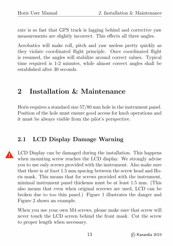
rate is so fast that GPS track is lagging behind and corrective yawmeasurements are slightly incorrect. This effects all three angles.
Aerobatics will make roll, pitch and yaw useless pretty quickly asthey violate coordinated flight principle. Once coordinated flightis resumed, the angles will stabilize around correct values. Typicaltime required is 1-2 minutes, while almost correct angles shall beestablished after 30 seconds.
2 Installation & Maintenance
Horis requires a standard size 57/80 mm hole in the instrument panel.Position of the hole must ensure good access for knob operations andit must be always visible from the pilot’s perspective.
2.1 LCD Display Damage Warning
LCD Display can be damaged during the installation. This happenswhen mounting screw reaches the LCD display. We strongly adviseyou to use only screws provided with the instrument. Also make surethat there is at least 1.5 mm spacing between the screw head and Ho-ris mask. This means that for screws provided with the instrument,minimal instrument panel thickenss must be at least 1.5 mm. (Thisalso means that even when original screews are used, LCD can bebroken due to too thin panel.) Figure 1 illustrates the danger andFigure 2 shows an example.
When you use your own M4 screws, please make sure that screw willnever touch the LCD screen behind the front mask. Cut the screwto proper length when necessary.
13 © Kanardia 2019

Horis User Manual 2.1 LCD Display Damage Warning
Figure 1: Screw can damage LCD screen behind the mask.
Notice LCD behind the bezel.Too long screw will break it.
Figure 2: Example of broken LCD screen. Edge of the LCD displayis visible behind the bezel.
14 © Kanardia 2019

Horis User Manual 2.2 Mounting Procedure
2.2 Mounting Procedure
The mounting screw holes are located on a circle of 66/89 mm diam-eter. The instrument is mounted using three screws type M4 and oneM6 insert1. To prevent internal stresses, please make sure that theinstrument panel is flat. The fourth hole is used for the knob axle.Figure 3 illustrates the mounting hole.
Remove the mounting screws from the instrument and then removethe knob. Use finger nail or sharp knife to remove the cap fromthe knob, but be careful not to cut the cup away. Once the cap isremoved, use flat screwdriver and loosen the screw. Slide the knobfrom its axle.
Horis 80 has an additional M6 nut that is used as an axle guide. Thisnut must be also removed.
Insert the instrument from the back side of the instrument panel.Fix three mounting screws. In the Horis 80 case, fix also the M6nut (axle guide). Then insert the knob back to the axle, tighten theknob. Please make sure it does not rub the panel and ensure thatit can be pushed in and out for the system operation. Put the capback.
2.3 Space Behind the Panel
Horis requires only minimal space behind the instrument panel. Depthof housing is 48 mm, connectors require additional 19 mm and cablesand tubing require about 20 mm as shown on Figure 4.
2.4 Connections
Figure 5 illustrates all connections at the back side of the instrument.
1 Only Horis 80 mm.
15 © Kanardia 2019

Horis User Manual 2.4 Connections
(a) 57 mm
(b) 80 mm
Figure 3: Instrument panel cutout and mounting holes. Some toler-ance has been incorporated. Warning: Figures are not inscale.
Horis must be connected to the pitostatic system.AHRS will not work properly when pitostatic is not connected.
2.4.1 Static - Pst
The instrument must be connected to the static pressure source.Static source is usually obtained from pressure sources located onfuselage side surfaces or from the static port on pitot tube.
For the connection, use a tube with 4 mm inner diameter and about 8mm outer diameter. Locate the existing tube, cut it at an appropriateplace and insert a T junction. Install a new tube from junction tothe instrument.
16 © Kanardia 2019

Horis User Manual 2.4 Connections
Cle
aran
ce f
or
cab
les
and
pit
o-s
tati
c tu
be
s.
48 mm19 mm20 mm
Figure 4: Side view of Horis. Only minimal space is required behindthe panel. Figure shows 57 mm version, but side dimensionsfor 80 mm Horis are even smaller (40 mm depth).
Figure 5: Back view of the instrument with connections. 57 mm ver-sion is shown.
It is highly recommended to keep the static tubing as short as pos-sible. The tubing must avoid sharp bends and twists. The tubingmust be airtight. Water must not be allowed to enter the tubing.
We strongly recommend labelling each tube before connecting to Ho-
17 © Kanardia 2019

Horis User Manual 2.4 Connections
ris or any other instrument. If you ever have to remove Horis fromthe instrument panel, this will help a lot during re-installation.
Two standard plastic T junctions are included in the Horis package.
2.4.2 Total Pressure - Ptot
Total pressure connection comes from the pitot tube. Same principlesas with static connection apply.
2.4.3 CAN Bus
Connection to the CAN bus is optional and is not required for normaloperation.
When Horis is not connected to the bus, a terminator plug must beinserted into one CAN connector. The terminator plug is a plainRJ45 plug with 120 Ω resistor connected across pins 4 and 5, whilepins 1,2,3 and 6,7,8 are not connected.
Figure 6 and Table 4 defines the pin out of the CAN bus.
1 … 8 1 … 8
Figure 6: Illustration of the pin out of the CAN ports.
When connected to the bus, Horis will transmit a large amount ofinformation: attitude, altitude, position, temperature, baro-settings,health status etc. Slave units connected on the bus (round altimeter,airspeed indicator, etc.) are capable of using this information.
Use standard RJ45 Ethernet cable to connect Horis with other Ka-nardia equipment. Both connectors are equivalent.
18 © Kanardia 2019

Horis User Manual 2.4 Connections
Pin Description1 +12V out.2 +12V out.3 +12V out.4 CAN low.5 CAN high.6 GND – ground.7 GND – ground.8 GND – ground.
Table 4: Description of pins for the CAN bus communication.
2.4.4 Power - PWR
Connect supplied power cable at the back of the instrument. Powerconnector has a notch on one side, which protects against wrongpolarity, see Figure 7.
+12 V … red
GND … blue
Figure 7: Pins of the power connector.
Connect blue lead to negative (ground) terminal and red lead topositive (+12-24 V) terminal.
A 1 ampere slow fuse or similar shall be used on the positive lead.
2.4.5 GPS Antenna - GPS
Please consider mounting GPS antenna, as follows:
19 © Kanardia 2019

Horis User Manual 2.4 Connections
Find a good spot in a cabin where the antenna is able to seeblue sky during most of the aircraft movement. Such a goodspot can be usually found on the top of the instrument panelcover, just below the canopy.
Mounting surface should be flat, clean and rigid.
Avoid close proximity to any transmitting antennas like radiostations, transponders or any other active GPS antennas (GPSantennas may interfere each other).
Antenna must not be covered or obstructed by metals (met-als sheets, rods) or any other conductive material (like carbonfibres).
The triangle/GPS text must point upwards, to the sky. Forthe installation use self-adhesive tape and fix the antenna ona rigid and clean surface. Supplied antenna is not intended tobe installed on the aircraft exterior. If you need to install theantenna on the external surface, search a suitable antenna inyour local avionics shop. Any 3.3 V active antenna with SMAmale connector can be used.
The antenna is used as an additional stabilisation of artificial horizonand as a source for the tracking azimuth.
2.4.6 Outside Air Temperature - OAT
Outside air temperature (OAT) probe is shipped with Horis. Thisis a digital temperature sensor2 glued inside a threaded aluminiumhousing. Default OAT cable length is 1.5 meters but other lengthsare available on request.
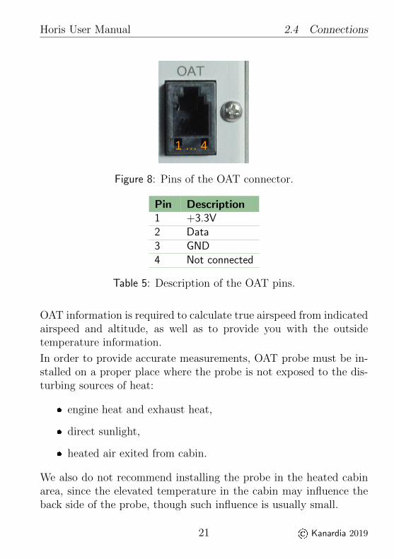
OAT connector is standard RJ12 type, as shown on Figure 8. De-scription of individual pins is given in Table 5.
2 Digital thermometer – DS18B20.
20 © Kanardia 2019
Horis User Manual 2.4 Connections
1 … 4
Figure 8: Pins of the OAT connector.
Pin Description1 +3.3V2 Data3 GND4 Not connected
Table 5: Description of the OAT pins.
OAT information is required to calculate true airspeed from indicatedairspeed and altitude, as well as to provide you with the outsidetemperature information.
In order to provide accurate measurements, OAT probe must be in-stalled on a proper place where the probe is not exposed to the dis-turbing sources of heat:
engine heat and exhaust heat,
direct sunlight,
heated air exited from cabin.
We also do not recommend installing the probe in the heated cabinarea, since the elevated temperature in the cabin may influence theback side of the probe, though such influence is usually small.
21 © Kanardia 2019

Horis User Manual 2.4 Connections
Please follow these steps to install the OAT probe:
1. Locate a spot in the aircraft taking into account the consider-ations from above and drill a φ 8 mm hole.
2. Remove the external nut from the probe but keep the washer,internal nut and plastic insulation tube on the probe.
3. Install the probe into the hole from the interior. Guide thecable to the Horis back panel.
4. Apply some lock-tight and thread the external nut to the probe.The lock-tight is necessary to avoid losing the cap due to vi-brations.
5. Tighten the internal nut so that the probe sits firmly and applylock-tight on the nut. Do not over tight it.
6. Slide the plastic insulation tube over the exposed threads of theprobe and cover as much threads as possible. Shrink the tubeusing hot air blower. Do not use open flame. Plastic insulation(shrink) tube also serves as thermal insulation for the sensorlocated in the tip.
2.4.7 RS-232 Port (NMEA Out)
Important: Instruments produced before 1.7.2016 may not have thisport active.
Note: Horis 57 model produced since Jan 2020 is using differentconnector. See section 2.4.8 on page 24.
The RS-232 port is used for communication with other instruments.You need a standard RJ12 (6P6C) connector to connect to the port.The table 6 defines the pinout and figure 9 illustrates pin orderingand connector position.
22 © Kanardia 2019

Horis User Manual 2.4 Connections
Figure 9: Illustration of the pin out of the RS-232 port.
Pin Description1 GND – ground.2 RX – receive data.3 TX – transmit data.4 Not used.5 Not used.6 +12V out – used to power some device, max 500 mA.
Table 6: Description of pins for the serial RS-232 communication.
In most cases you only connect two or three pins – pins 1-3. Pins 4and 6 are used only when you use Horis as a power source.
By default Horis transmits NMEA GGA and RMC sentences on pin3. In order to listen to these sentences, you need to connect pin 1(GND) with GND on the listening device and pin 3 (TX) with theRX pin on the listening device. Default settings are 9600 baud, 8bit data size, no parity and one stop bit a.k.a. 9600 8N1. You canchoose different baud rate, but you can’t change parity or stop bit.
23 © Kanardia 2019

Horis User Manual 2.4 Connections
2.4.8 D-sub 9 Port
This port is used only on Horis 57 models produced after February2020. It replaces the port shown on figure 9. The new D-sub 9 porthas more pins and allows for more features in future.
1 5
6 9
Figure 10: Illustration of the pin out on the D-sub 9 port.
Pin Description1 Reserved for future use, do not connect.2 Reserved for future use, do not connect.3 Reserved for future use, do not connect.4 +12V out – used to power some device, max 500 mA.5 GND6 RS-232 RX 1 (receive line)7 RS-232 TX 1 (transmit line)8 Reserved for future use, do not connect.9 Reserved for future use, do not connect.
Table 7: D-sub 9 pin description.
Currently only transmit line can be used for GPS NMEA senstences.Typically, pin 5 (GND) and pin 7 (TX 1) are connected to somereceiveing device.
Other pins are currently not supported by firmware and may becomeactive with future updates.
24 © Kanardia 2019
Horis User Manual 2.5 Levelling AHRS
2.5 Levelling AHRS
During assembly of the AHRS unit into the Horis and during in-stallation of Horis into the instrument panel, a small misalignmentmay appear. This means that internal axes of the AHRS unit arenot parallel to the aircraft axes – the AHRS unit is slightly rotated.Such misalignment can be perfectly adjusted without loss of precisionusing the procedure described next.
Place aircraft on flat surface and put it into cruise attitude.Use supports and lift tail or nose if necessary.
Please make sure that aircraft is level for both, roll and pitch.Make also sure that Horis is turned on for at least five minutes –this warms up the internal electronics and stabilises numericalfilters.
Once the aircraft is level and steady, select the AHRS level op-tion from the settings menu to start the automatic calibrationprocedure. See also Section 4.6.4 on page 43.
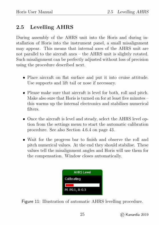
Wait for the progress bar to finish and observe the roll andpitch numerical values. At the end they should stabilise. Thesevalues tell the misalignment angles and Horis will use them forthe compensation. Window closes automatically.
Figure 11: Illustration of automatic AHRS levelling procedure.
25 © Kanardia 2019

Horis User Manual 2.6 Compass Calibration
Horis can easily compensate misalignment in roll and pitch up to20or even more. However it can’t compensate for heading misalign-ment. Thus, please make sure that the part of instrument panelwhere Horis is mounted is perpendicular to the flight direction. Ifthis is not the case, Horis will not function properly, even if roll andpitch compensations were perfectly made.
2.6 Compass Calibration
If Magu magnetic compass is connected to Horis, then it is essentialto perform the compass calibration procedure. Please refer to theMagu manual (not included here) for the compass installation andcalibration procedure. The latest versions of manuals can be alwaysfound on our web site www.kanardia.eu.
2.7 Maintenance
No special maintenance is required. A static leak test should beperformed annually and calibration check biannually. In case of smalldeviation use the procedure described in Section 4.6.8.
2.8 Repair
Horis has no repairable parts inside. In case of malfunction it mustbe sent to factory for repair.
2.9 Horis Use in Gliders
Experience shows that Horis can be successfully used also in gliders.Sustained turns do not effect Horis, as long as turns are coordinated(no significant slips or skids) and even in the continues slip case, onlyminor error in the bank appears.
26 © Kanardia 2019
Horis User Manual 2.9 Horis Use in Gliders
However, low battery voltages may affect Horis operation. AlthoughHoris works also with voltages as low as 9 V, a problem may appeareven at higher voltages. A typical scenario (where gyros inside Horisgo crazy) happens when battery is at its low end (say at 11 V – withonly one or two percent of capacity left). All seems to work OKuntil push-to-talk radio button is pressed. The radio transmissionrequires much more amperage (power) from the battery. For a veryshort time, measured in milliseconds, voltage may drop down to 3-4V, which in turn causes instability of electronic gyros inside Horis.Unfortunately, gyros do not recover when voltage returns back tonormal and hard reset (power off/on) is necessary.
This problem can be avoided in two ways.
Most gliders use two main batteries. When Horis is needed,always fly on the battery which is more full.
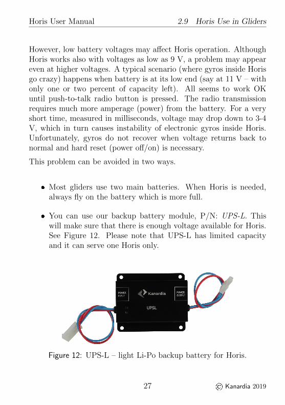
You can use our backup battery module, P/N: UPS-L. Thiswill make sure that there is enough voltage available for Horis.See Figure 12. Please note that UPS-L has limited capacityand it can serve one Horis only.
Figure 12: UPS-L – light Li-Po backup battery for Horis.
27 © Kanardia 2019

Horis User Manual 2.10 Software Update
2.10 Software Update
2.10.1 Update With a Blu Module
Most Horis models have no means (SD card, USB slot) for a directsoftware update. It can be updated with a help of the Blu deviceand an Android telephone or tablet, which is running our Kanjaapp. Blu is plugged at the back of Horis and once a communicationwith Kanja is established, new software is transferred to Horis andAD-AHRS module. Figure 13 shows the Blu module.
Figure 13: A small CAN bus to Bluetooth bidirectional interfacemodule.
Below are step-by-step instructions for the update. Refer also to BluManual for more details.
1. Plug Blu device into one of free CAN ports.
2. Start the Kanja app on the Android device. Each time Kanjais started, it automatically downloads the latest firmware fromour server.
3. Connect Kanja and Blu device. Once connection is established,a list of units detected on the CAN bus will appear. As min-imum, Horis and Airu must be on the list. The exact list
28 © Kanardia 2019
Horis User Manual 2.10 Software Update
depends on number of Kanardia instruments connected to theCAN bus.
4. Select Horis from the list and then select Update.
5. Confirm the selection – press Yes and Kanja will start thefirmware update.
6. Once the update has been completed, press the Back arrowon the top left corner of the Kanja app. This brings back thedevice list.
7. Select Airu from the list and then select Update. This willupdate the AD-AHRS-GPS module, which is hidden inside theHoris. (Slave Horis does not have such module inside.) Redcrosses will appear on the Horis screen during the update. Thisis normal.
8. Once the update has been completed and red crosses has dis-appeared, Kanja can be disconnected and Blu removed. Newfirmware is installed and ready to use.
2.10.2 Update With Micro SD Card
Only Horis models that have SD card slot can be updated this way. IfHoris does not have the SD card slot, Blu must be used. See section2.10.1.
1. Download the latest Horis softare from our web site and copyit to the micro SD card. The filename must begin with Horis
and it must end with .bin. For example, Horis360.bin is avalid name. 360 is used to identify version 3.6.
2. Insert the SD card into Horis and power it on. Horis will checkfor the precence of the SD card during boot cycle.
29 © Kanardia 2019

Horis User Manual 3. Horis Screens
3. When correct file is found on the SD card, an update proce-dure will commnece. A black/white flasing screen informs thatupdate is in progress. It takes about 9-10 seconds to finsih theupdate.
4. After the update, Horis displays a window telling about updatesuccess. This window is dislayed only once after each successfulupdate.
Note: Horis will not allow downgrade. For example, if current Horisversion is 4.5, it will not accept any updates older then 4.5.
If flashing finishes after 4 seconds and the update success window isnot shown, then the update file is probably corrupt. Download thefile again from our web site and try again. Do not forget to use saferemove option after copy, before the SD card is removed from PC.
3 Horis Screens
Horis can show four different screens: AD-AHRS, Direction Indica-tor, G-Meter and Chrono. Please refer to section 4.6.5 on how tochange the order of screens or how to enable/disable them.
Push the knob to change between screens.
3.1 AD-AHRS
Typically, the AD-AHRS screen appears as soon as Horis is poweredon. The screen layout has been optimised to show all relevant flightinformation. Figure 14 shows the screen.
The following parameters are shown on the screen:
1. Indicated airspeed indicator shows airspeed obtained from thedifferential pressure sensor and the speed tape.
30 © Kanardia 2019

Horis User Manual 3.1 AD-AHRS
Figure 14: Horis AD-AHRS screen with markings.
2. GPS status signal. Three green bars indicate normal operation(3D fix). A small green diamond next to three green bars meansthat GPS position is further enhanced with SBAS (EGNOS,WAAS, etc.) One yellow bar indicates marginal 2D fix andand a red cross of the gray bars indicates loss of signal. Notethat GPS reception is not mandatory for AHRS – AHRS willfunction properly without it.
Ground speed is shown left of the GPS status signal after theGPS fix was obtained. (Note: GS is not shown on Figure 14.)
3. Azimuth (direction) indication. Dashes represent that azimuthwas not yet established (You need to move for GPS receiver tocalculate the azimuth.) Once established tracking from GPSwill be shown.
4. Azimuth markings. The left letter tells which azimuth referenceis used. It can be either:
T ... true azimuth.
31 © Kanardia 2019
Horis User Manual 3.1 AD-AHRS
M ... magnetic azimuth.
The right letter tells the source for the azimuth. It can beeither:
T ... tracking taken from the GPS receiver.
H ... heading taken from AHRS coupled with electronicmagnetic compass3. By heading we mean direction intowhich nose is pointed. In case of strong wind this can besignificantly different from tracking.
Default combination is TT. This means true azimuth and track-ing obtained from GPS.
5. Altitude indicator is composed of altitude value and altitudetape moving in the background.
6. Rate of climb a.k.a. vario. Small bar shows climb or descentand a value on the bottom expresses it in numbers.
7. Baro correction a.k.a. QNH.
8. Outside air temperature a.k.a. OAT. Numerical value is dis-played.
9. True air speed a.k.a. TAS is derived information obtained fromindicated airspeed, outside air temperature and static pressure.
10. The inclinometer (slip-skid) indicator.
3 Electronic magnetic compass (Magu) is an external device and is not a part ofHoris system. With Magu connected and properly calibrated, the AD-AHRSunit in Horis can determine heading and it can calculate wind direction andspeed.
32 © Kanardia 2019

Horis User Manual 3.2 Directional Indicator
11. Artificial horizon with a reference line, roll arc and pitch lines.Reference line can be used for 45turns, short roll arc dashesdefine 15and 30marks and longer dash defines 45mark. Inpitch, long line defines 10, medium 5and short 2.5markings.
12. Right: The turning rate scale. Yellow horizontal bar is used toshow turning rate. Depending on settings, inner black pointsindicate either standard turn (3per second), double turn (6persecond) or glider turn (12per second). Outer black points in-dicate twice the turn rate of inner points.Below: Relative wind indication arrow, wind speed and di-rection. This is shown only when Magu (electronic magniticcompass) is connected to CAN bus.
Some elements of the AD-AHRS screen are configurable. Please referto Section 4.6 starting on page 40 for more details.
3.2 Directional Indicator
The Directional Indicator screen is optional and it may not be enabledby default. You have to enable it in settings. Please see section 4.6.5on page 44 for the details.
Typically direction indicator is used as a second screen.
Figure 15 shows the screen with several important points marked.
1. The yellow line as an extension of aeroplane symbol points tocurrent azimuth (direction). The azimuth is also shown in nu-meric value, followed by two letters. Their meaning is identicalto description of item 4 on page 31. Below the azimuth numberis also written source of the data. This can be:
Compass when Magu is direction source or
33 © Kanardia 2019

Horis User Manual 3.3 G-Meter
Figure 15: Direction Indicator screen with markings.
GPS track when GPS track is used as direction source.
2. Heading bug is used as reference marker. Simply turn the knobto move the reference marker.
3. Heading bug value is shown next to the knob. It tells currentvalue/position of the bug.
4. Ground speed is shown here for your convenience.
5. GPS status in graphical form as is described in item 2 on page31.
3.3 G-Meter
The G-Meter screen is optional and it may not be enabled by default.When not visible, it must be enabled in settings. Please see section4.6.5 on page 44 for the details.
34 © Kanardia 2019
Horis User Manual 3.3 G-Meter
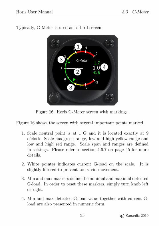
Typically, G-Meter is used as a third screen.
Figure 16: Horis G-Meter screen with markings.
Figure 16 shows the screen with several important points marked.
1. Scale neutral point is at 1 G and it is located exactly at 9o’clock. Scale has green range, low and high yellow range andlow and high red range. Scale span and ranges are definedin settings. Please refer to section 4.6.7 on page 45 for moredetails.
2. White pointer indicates current G-load on the scale. It isslightly filtered to prevent too vivid movement.
3. Min and max markers define the minimal and maximal detectedG-load. In order to reset these markers, simply turn knob leftor right.
4. Min and max detected G-load value together with current G-load are also presented in numeric form.
35 © Kanardia 2019

Horis User Manual 3.4 Chrono
Knob rotation will reset min and max markers and values.
3.4 Chrono
The Chrono screen is optional and it may not be enabled by default.When not visible, it must be enabled in settings. Please see section4.6.5 on page 44 for the details.
1
2
3
4
Figure 17: Horis chrono screen with markings.
Figure 17 shows the screen with several important points marked.
1. UTC time and GPS reception symbol. Horis gets time fromGPS and the time will be shown only when GPS signal is avail-able.
2. Local, sunrise and sunset times. They all depend on GPS signalas well and they are visible only when GPS signal is available.Local time requires correct time zone - see section 4.6.10 formore details.
36 © Kanardia 2019

Horis User Manual 4. Operations
3. Stopwatch can be used by turning the knob. Symbols on theleft an right side of the stopwatch time define available actions.
Turn right to start the stopwatch.
Turn either left or right to stop for lap.
Turn left to reset or right to continue.
You can switch the pages even when the stopwatch is running.In this case, a stopwatch symbol appears on the top right partof each screen.
4. Flight time starts counting automatically when takeoff condi-tions is detected and stops when landing is detected. The timerestarts with zero on next takeoff.
Note, false landings may be detected when Horis is used in arotorcraft. A slow speed or hovering will falsely trigger landingevent and flight time will reset when movement is resumed.
4 Operations
Horis is operated using a single push knob. You can do the followingactions with the knob:
Rotate the knob to change something.
Push the knob to confirm something.
Push the knob for a few seconds to enter a main menu4.
4 We opt for this approach to avoid accidental activation of the main menuduring flight.
37 © Kanardia 2019

Horis User Manual 4.1 Adjusting QNH
Horis does not have a close button. When a window is opened andediting mode is not active, a white bar appears across the windowcaption. This bar indicates the timeout. When the bar is full, windowcloses automatically.
There are only three flight operations: adjusting the QNH value,setting the neutral pitch and changing the brightness. There aremore settings, but they are not accessed frequently.
Figure 18: Illustration of Horis main menu. The Pitch Reset optionis the default one.
4.1 Adjusting QNH
QNH is adjusted by turning the knob when you are on AD-AHRSpage. As QNH changes, the indicated altitude changes accordingly.All changes are visible on the screen.
4.2 Adjusting Direction Indicator
When the Direction Indicator screen is visible, the bug is set byturning the knob. Slow turning changes the bug position for onedegree while quick turning moves the bug in larger steps. All changesare visible on the screen.
38 © Kanardia 2019

Horis User Manual 4.3 Reseting G-Load
4.3 Reseting Min And Max G-Load Markers
When the G-Meter screen is visible simply turn the knob to resetmarkers. All changes are visible on the screen.
4.4 Setting the Neutral Pitch
Neutral pitch – zero pitch indication line changes with the aeroplanegross weight and flight regime. Horis allows resetting neutral pitchfor the current flight regime.
Open the main menu by pushing the knob for a few seconds.The Pitch Reset option is selected by default. See Figure 18.
Push the knob once again in order to activate the option.
Horis needs a few seconds to adjust for new neutral pitch value. Donot use this function in a turbulence or in an unstable flight regime.
4.5 Diminishing the Brightness
Horis starts with a pre-defined initial brightness. Default initialbrightness is 100%. If the brightness is not adequate, it can bechanged using procedure below:
Open the main menu by pushing the knob for a few seconds.
Rotate the knob to select the Brightness option and push itto start the change.
Rotate the knob to adjust the brightness to an appropriatelevel.
Push the knob again to accept new value.
39 © Kanardia 2019

Horis User Manual 4.6 Settings
Wait for the main menu to close automatically.
Initial (start-up) brightness is specified in settings. See section 4.6.14for more details.
4.6 Settings
Horis can be configured with several options described next. Thesettings screen is accessed via the main menu. Figure 19 illustratesthe settings menu and some of the options.
Figure 19: Horis settings menu and major options.
4.6.1 Units
This option allows fine tuning of units for almost any parameter ofthe main screen. Figure 20 shows the window where units may bechanged. Table 8 lists all possible options.
4.6.2 Airspeed
This option is used to define the speed tape colours of the airspeedindicator. Figure 22 illustrates the window and figure 21 definesmeanings of individual values on the speed tape.
40 © Kanardia 2019

Horis User Manual 4.6 Settings
Unit Type OptionsHeading True, MagneticSpeed kts, km/h, mphVario (rate of climb) m/s, ft/min, ktsWind m/s, km/h, ktsAltitude meter, feetQNH hPa, inHgTemperature C, F
Table 8: Unit options.
Figure 20: Tuning the units.
The following values are used:
Start defines the bottom of the speed tape. At this speed thetape starts. Typically, this is the stall speed.
Yellow end defines the end of the low speed part of the yel-low range. Put into another words, speeds between Start andYellow end define the bottom yellow part of the speed tape.
If you do not want to have yellow range on the bottom part,set Yellow end to the same value as Start.
Green end defines the end of the green range on the speed tape.
41 © Kanardia 2019

Horis User Manual 4.6 Settings
VNE defines VNE (velocity never exceeded) airspeed. At thisspeed the yellow upper range ends and the red range begins.The red range never ends. Yellow upper range is defined auto-matically between Green end and VNE.
You can also mark valid extended flap position region on the speedtape. In this case you also set:
White start defines the start of the white part.
White end defines the end of the white part.
Figure 21: Definition of the speed tape colours.
Figure 22: Illustration of the airspeed window used to define thespeed tape.
42 © Kanardia 2019
Horis User Manual 4.6 Settings
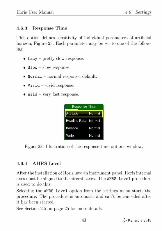
4.6.3 Response Time
This option defines sensitivity of individual parameters of artificialhorizon, Figure 23. Each parameter may be set to one of the follow-ing:
Lazy – pretty slow response.
Slow – slow response.
Normal – normal response, default.
Vivid – vivid response.
Wild – very fast response.
Figure 23: Illustration of the response time options window.
4.6.4 AHRS Level
After the installation of Horis into an instrument panel, Horis internalaxes must be aligned to the aircraft axes. The AHRS Level procedureis used to do this.
Selecting the AHRS Level option from the settings menu starts theprocedure. The procedure is automatic and can’t be cancelled afterit has been started.
See Section 2.5 on page 25 for more details.
43 © Kanardia 2019
Horis User Manual 4.6 Settings
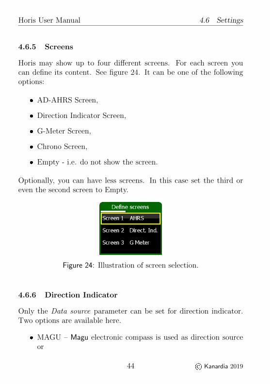
4.6.5 Screens
Horis may show up to four different screens. For each screen youcan define its content. See figure 24. It can be one of the followingoptions:
AD-AHRS Screen,
Direction Indicator Screen,
G-Meter Screen,
Chrono Screen,
Empty - i.e. do not show the screen.
Optionally, you can have less screens. In this case set the third oreven the second screen to Empty.
Figure 24: Illustration of screen selection.
4.6.6 Direction Indicator
Only the Data source parameter can be set for direction indicator.Two options are available here.
MAGU – Magu electronic compass is used as direction sourceor
44 © Kanardia 2019

Horis User Manual 4.6 Settings
GPS track – GPS track is used as direction source.
If MAGU is selected as direction source and Magu is not present, thisselection will be ignored and Horis will take GPS track instead.
If MAGU is present and GPS track is selected as data source, mag-netic compassed is disabled. This option can be useful, when MAGUis connected to the CAN bus, but its calibration is poor or one of itssensor is defective.
4.6.7 G-Meter
The G-Meter screen can be configured with the following parameters,see also figure 25:
Scale defines overall range of the scale shown on the screen.You can choose the following ranges:
– -2 : 4 defines low end to -2 G and upper end to +4 G.
– -3 : 5 defines low end to -3 G and upper end to +5 G.
– -5 : 7 defines low end to -5 G and upper end to +7 G.
Red low defines negative G red limit.
Green low defines negative G green limit.
Red high defines positive G red limit.
Green high defines positive G green limit.
Any valid range between green and red values is drawn in yellow colorautomatically.
45 © Kanardia 2019

Horis User Manual 4.6 Settings
Figure 25: Illustration G-Meter parameters.
4.6.8 Pitostatic Offset
Modern digital sensors used for IAS and altitude measurements maydrift a little bit over time, especially after being exposed to a pro-longed period of severe cold. Selecting the Pitostatic Offset op-tion from the settings menu opens a window illustrated on Figure 26.This window allows you to change altitude and velocity (airspeed)offset.
Figure 26: Illustration of the sensor offset window.
4.6.9 Turn Rate
Horizontal turn rate bar that appears on the AHRS screen can havedifferent sensitivities:
46 © Kanardia 2019

Horis User Manual 4.6 Settings
Standard 3/s (two minutes turn),
Double 6/s (one minute turn),
Glider 12/s (30 seconds turn).
This selection defines the inner dot of the turn rate bar. So, if youwant to keep the correct turn rate, you have to aim to the inner dot.The outer dot defines twice the turn rate of inner dot.
Altitude
In order to set the altitude offset you need a reference altimeter. Setthe QNH on Horis and reference altimeter to the same value, say1013 hPa.
Use the knob to select the altitude offset frame. This is alreadyselected when the window is opened.
Push the knob to start the offset.
Rotate the knob in order to match the altitude shown belowthe frame with the altitude shown by the reference altimeter.Horis shows two values: Pst is the static pressure and is shownin hPa and Alt is the altitude shown in metres. These metricunits are used regardless the units selected by user.
Push the knob to finish editing and wait for timer to close thewindow.
47 © Kanardia 2019

Horis User Manual 4.6 Settings
Velocity
Important: Please make sure that aeroplane is either inside hangaror there is absolutely no wind and that pitot tube is not covered.Failing to do so may result in wrong offset and it may worsen airspeedprecision.
Rotate the knob and highlight the velocity (airspeed) frame.
Push the knob to start editing.
Rotate the knob and observe the differential pressure value be-low. The differential pressure value shall read zero (or almostzero).
Push the knob to finish editing and wait for the timer to closethe window.
4.6.10 Time Zone
Set the local time offset. Positive values are used for countries withEastern longitudes, while Western latitudes have negative values.
Horis does not automatically adjust for Summer daylight savingstime.
4.6.11 Compass Calibration
This option is available only when Magu magnetic compass is con-nected to the CAN bus. Please refer to the Magu manual for thedetails.
48 © Kanardia 2019
Horis User Manual 4.6 Settings
4.6.12 Compass Offset
This option is available only when Magu magnetic compass is con-nected to the CAN bus. Please refer to the Magu manual for thedetails.
4.6.13 NMEA Out
Here you can select the baudrate for the RS232 output port. 9600baud is the default value.
4.6.14 Initial Brightness
Use this option to set the Horis LCD display brightness at startup.Default value is 100%, but if find Horis display too bright, you mayset it to a lower value here.
4.6.15 GNSS Info
Horis can show the GNSS satellite constallation currently in use.Figure 27 illustrates an example.
The window shows positions of the satellites on the sky. GPS con-stellation is represented with green dots and Glonass is representedwith blue dots. All detected positions are shown. Grey color meansthat a satellite is being tracked, but it is not being used in solution.Under unobstructed sky, satellites should be evenly distributed.
Numbers in the top left corner tell how many of visible satellites areused in solution. For example, GPS 6/9 means that 9 GPS satellitesare detected but 6 are used in position calculation.
49 © Kanardia 2019

Horis User Manual 4.6 Settings
Figure 27: An example of GNSS constallation where GPS andGlonass satellites are visible. Distribution is poor. North-ern latitudes are not present.
HDOP, VDOP and PDOP5 values indicates quality of the solution.The meaning of the DOP values is given in Table 9. In general,HDOP shall be always be less than 5.
DOP Rating Description< 1 Ideal Highest possible confidence level.1 − 2 Excellent Measurements are considered accurate.2 − 5 Good Still acceptable for route navigation.5 − 10 Moderate Position is useful, but it should be improved.10 − 20 Fair Measurements indicate a very rough location.> 20 Poor Inaccurate measurements.
Table 9: How to interpret DOP values.
Solution fix is shown in the top right corner. It can be one of thefollowing values:
5 DOP ... Dilution of precision. HDOP ... horizontal, VDOP ... vertical andPDOV ... combined position.
50 © Kanardia 2019

Horis User Manual 4.6 Settings
None ... there is no fix. Position is not known.
2D fix ... only 2D fix is obtained. Position measurements are poor.
3D fix ... 4 or more satellites are used in solution. Position qualityshould be good. See also DOP.
3D+SBAS ... 3D position is further enhanced with the SBAS system.
4.6.16 Security
Access to the settings option of the main menu can be protectedby PIN (personal identification number). By default, there is noprotection and Horis does not ask for PIN.
In order to set your own PIN, select the Security option and enternew PIN. You have to confirm the PIN and if they match, a new PINis set. This means that the next time you enter the Settings menu,Horis will ask for this PIN.
If you forgot the PIN, enter 75213 and you will get access to theSettings menu.
You can also set an empty PIN. In this case Horis does not ask forpassword.
Figure 28: You can specify your own PIN to limit access to theSettings menu.
51 © Kanardia 2019

Horis User Manual 4.6 Settings
4.6.17 About
The About window shows some relevant information about Horis:
S/N – serial number of Horis.
SW. ver. – version of the software in Horis.
SW. date – release date of the software in Horis.
Airu – Software version of the AD-AHRS unit.
Magu – Software version of magnetic compass unit, when suchunit is connected to the CAN bus.
Figure 29: An example of the about window.
52 © Kanardia 2019
Horis User Manual 5. Limited Conditions
5 Limited Conditions
Although a great care was taken during the design, production, stor-age and handling, it may happen that the Product will be defectivein some way. Please read the following sections about the warrantyand the limited operation to get more information about the subject.
5.1 Warranty
Kanardia d.o.o. warrants the Product manufactured by it againstdefects in material and workmanship for a period of twenty-four (24)months from retail purchase.
Warranty Coverage
Kanardia’s warranty obligations are limited to the terms set forthbelow:
Kanardia d.o.o. warrants the Kanardia-branded hardware productwill conform to the published specification when under normal usefor a period of twenty-four months (24) from the date of retail pur-chase by the original end-user purchaser (”Warranty Period”). If ahardware defect arises and a valid claim is received within the War-ranty Period, at its option and as the sole and exclusive remedyavailable to Purchaser, Kanardia will either (1) repair the hardwaredefect at no charge, using new or refurbished replacement parts, or(2) exchange the product with a product that is new or which hasbeen manufactured from new or serviceable used parts and is at leastfunctionally equivalent to the original product, or, at its option, if (1)or (2) is not possible (as determined by Kanarida in its sole discre-tion), (3) refund the purchase price of the product. When a refund isgiven, the product for which the refund is provided must be returnedto Kanardia and becomes Kanardia’s property.
53 © Kanardia 2019

Horis User Manual 5.1 Warranty
Exclusions and Limitations
This Limited Warranty applies only to hardware products manufac-tured by or for Kanardia that have the ”Kanardia” trademark, tradename, or logo affixed to them at the time of manufacture by Ka-nardia. The Limited Warranty does not apply to any non-Kanardiahardware products or any software, even if packaged or sold with Ka-nardia hardware. Manufacturers, suppliers, or publishers, other thanKanardia, may provide their own warranties to the Purchaser, butKanarida and its distributors provide their products AS IS, withoutwarranty of any kind.
Software distributed by Kanardia (with or without the Kanardia’sbrand name including, but not limited to system software) is not cov-ered under this Limited Warranty. Refer to the licensing agreementaccompanying such software for details of your rights with respect toits use.
This warranty does not apply: (a) to damage caused by use with non-Kanardia products; (b) to damage caused by accident, abuse, misuse,flood, fire, earthquake or other external causes; (c) to damage causedby operating the product outside the permitted or intended uses de-scribed by Kanardia; (d) to damage caused by service (includingupgrades and expansions) performed by anyone who is not a repre-sentative of Kanardia or an Kanarida Authorized Reseller; (e) to aproduct or part that has been modified to significantly alter function-ality or capability without the written permission of Kanardia; (f)to consumable parts, such as batteries, unless damage has occurreddue to a defect in materials or workmanship; or (g) if any Kanardiaserial number has been removed, altered or defaced.
To the extent permitted by applicable law, this warranty and reme-dies set forth above are exclusive and in lieu of all other warranties,remedies and conditions, whether oral or written, statutory, expressor implied, including, without limitation, warranties of merchantabil-
54 © Kanardia 2019

Horis User Manual 5.1 Warranty
ity, fitness for a particular purpose, non-infringement, and any war-ranties against hidden or latent defects. If Kanardia cannot lawfullydisclaim statutory or implied warranties then to the extent permittedby law, all such warranties shall be limited in duration to the dura-tion of this express warranty and to repair or replacement service asdetermined by Kanardia in its sole discretion. Kanardia does notwarrant that the operation of the product will be uninterrupted orerror-free. Kanardia is not responsible for damage arising from fail-ure to follow instructions relating to the product’s use. No Kanardiareseller, agent, or employee is authorized to make any modification,extension, or addition to this warranty, and if any of the foregoingare made, they are void with respect to Kanardia.
Limitation of Liability
To the extent permitted by applicable law, Kanardia is not responsi-ble for indirect, special, incidental or consequential damages resultingfrom any breach of warranty or condition, or under any other legaltheory, including but not limited to loss of use; loss of revenue; loss ofactual or anticipated profits (including loss of profits on contracts);loss of the use of money; loss of anticipated savings; loss of busi-ness; loss of opportunity; loss of goodwill; loss of reputation; loss of,damage to or corruption of data; or any other loss or damage how-soever caused including the replacement of equipment and property,any costs of recovering, programming, or reproducing any programor data stored or used with Kanardia products and any failure tomaintain the confidentiality of data stored on the product. Under nocircumstances will Kanardia be liable for the provision of substitutegoods or services. Kanardia disclaims any representation that it willbe able to repair any product under this warranty or make a prod-uct exchange without risk to or loss of the programs or data. Somejurisdictions do not allow for the limitation of liability for personal
55 © Kanardia 2019

Horis User Manual 5.2 TSO Information
injury, or of incidental or consequential damages, so this limitationmay not apply to you.
5.2 TSO Information — Limited Operation
This product is not TSO approved as a flight instrument. Therefore,the manufacturer will not be held responsible for any damage causedby its use. The Kanardia is not responsible for any possible damageor destruction of any part on the airplane caused by default operationof instrument.
56 © Kanardia 2019