Hopergy Quick User Guide - TASPAC · PDF fileHopergy Quick User Guide . 2 24 Web:...
32
Hopergy Quick User Guide
Transcript of Hopergy Quick User Guide - TASPAC · PDF fileHopergy Quick User Guide . 2 24 Web:...

Hopergy Quick User Guide

99299 924
Web:www.hopergy.com Email:[email protected] 2
Contents AUSTRALIAN WIND REGIONS FOR MAXIMUM RAIL SUPPORT SPACING ........................................................................................... 3 HOPERGY SELECT SERIES RAIL SYSTEM ..................................................................................................................................... 4
Select Rail Tile Spacing Table ...................................................................................................................................... 5 Select Rail Tin Spacing Table ...................................................................................................................................... 6 Select Rail Tilt Spacing Table ...................................................................................................................................... 7 Select Rail Tripod Spacing Table ................................................................................................................................. 9
HOPERGY SELECT-LITE SERIES RAIL SYSTEM ............................................................................................................................. 11 Select-lite Rail Tile Spacing Table.............................................................................................................................. 12 Select-lite Rail Tin Spacing Table .............................................................................................................................. 13 Select-lite Rail Tilt Spacing Table .............................................................................................................................. 14
HOPERGY KLIPLOK INTERFACE CLAMP SPACING TABLE ............................................................................................................... 16 HOPERGY GROUND MOUNT INSTALLATION GUIDE ................................................................................................................... 18 HOPERGY POLE MOUNT INSTALLATION GUIDE ......................................................................................................................... 20 SELECT SERIES RAIL SYSTEM AS/NZS 1170.2 CERTIFICATE ....................................................................................................... 22 SELECT-LITE SERIES RAIL SYSTEM AS/NZS 1170.2 CERTIFICATE ................................................................................................. 23 GROUND MOUNT PVGRID-I CERTIFICATE AS/NZS 1170.2 CERTIFICATE ..................................................................................... POLE MOUNT AS/NZS 1170.2 CERTIFICATE ..........................................................................................................................
. 9
. 9

Web:www.hopergy.com Email:[email protected] 3
Australian Wind Regions for Maximum Rail Support Spacing

Web:www.hopergy.com Email:[email protected] 4
Hopergy Select Series Rail System
Hopergy Select Series Rail is an optimized solution, it has THREE openings which make them compatible with a large variety of roof interface brackets. It is a smart system of engineered components that allows installers to quickly assemble .Its corrugated surfaces on both the rails and roof hooks ensure the secure connection of these parts. The loop design maximizes and distributes rail strength evenly throughout the length of the rails.
Select Series Rail

Web:www.hopergy.com Email:[email protected] 5
Select Rail Tile Spacing Table
For Up To 1600mm Long Panel (2 Rails)
Max. Support Spacing (mm)
Installation Region A Region B Region C Region D
Height(m) Center Edge Center Edge Center Edge Center Edge
5 Meters 2400 1740 1710 1200 1070 755 660 465
10 Meters 2050 1445 970 1000 965 680 595 420
For Up To 1960mm Long Panel (2 Rails)
Max. Support Spacing (mm)
Installation Region A Region B Region C Region D
Height(m) Center Edge Center Edge Center Edge Center Edge
5 Meters 1980 1390 1360 965 855 680 520 370
10 Meters 1630 1150 1130 800 775 545 475 335
Min.50mm embedment to existing timber rafters. For 1960mm Long Panels with 3 supporting rails, the maximum Spacing can be increased by 25%.

Web:www.hopergy.com Email:[email protected] 6
Select Rail Tin Spacing Table
For Up To 1600mm Long Panel (2 Rails)
Max. Support Spacing (mm)
Installation Region A Region B Region C Region D
Height(m) Center Edge Center Edge Center Edge Center Edge
5 Meters 1600 1220 1150 845 720 530 450 325
10 Meters 1350 1010 950 700 650 475 400 290
For Up To 1960mm Long Panel (2 Rails)
Max. Support Spacing (mm)
Installation Region A Region B Region C Region D
Height(m) Center Edge Center Edge Center Edge Center Edge
5 Meters 1350 975 940 675 600 420 350 260
10 Meters 1100 810 780 560 530 380 330 235
Min. M12Φ screws Australian standard or equivalent. Min. 35mm embedment to existing timber batten. Min. steel batten/ purlin thickness=0.6mm. For 1960mm Long Panels with 3 supporting rails, the maximum Spacing can be increased by 25%.
Web:www.hopergy.com Email:[email protected] 7
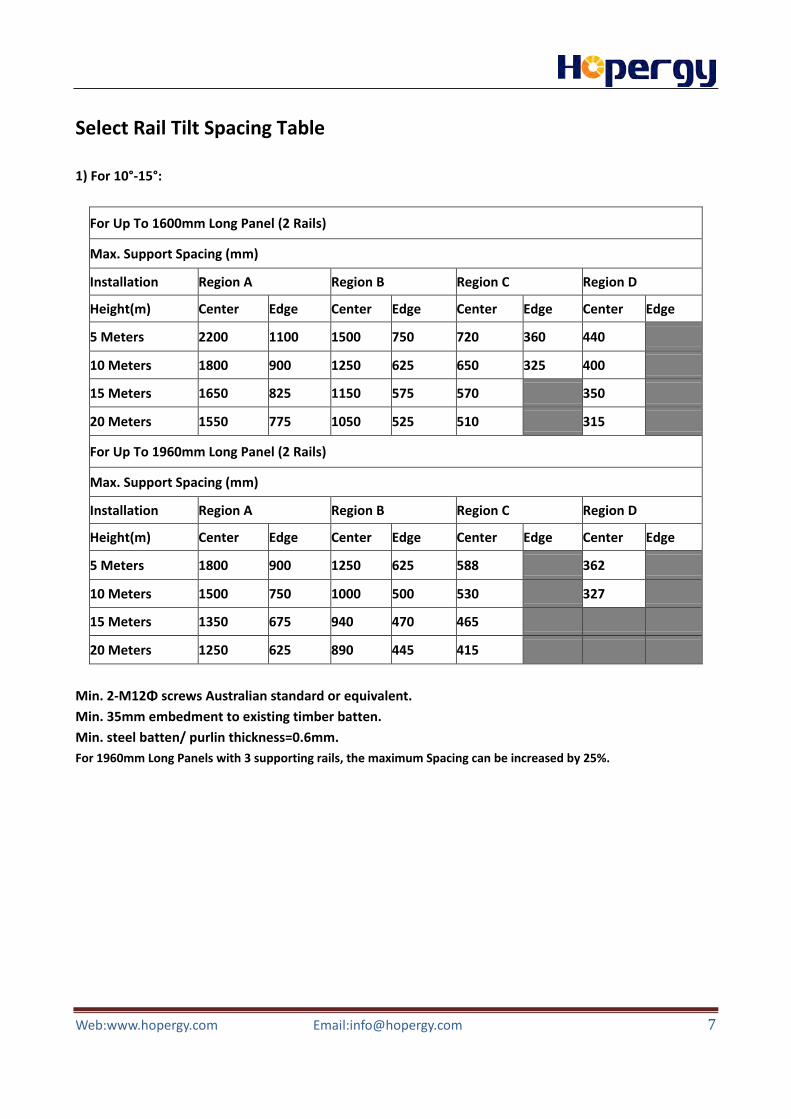
Select Rail Tilt Spacing Table
1) For 10°-15°:
For Up To 1600mm Long Panel (2 Rails)
Max. Support Spacing (mm)
Installation Region A Region B Region C Region D
Height(m) Center Edge Center Edge Center Edge Center Edge
5 Meters 2200 1100 1500 750 720 360 440
10 Meters 1800 900 1250 625 650 325 400
15 Meters 1650 825 1150 575 570 350
20 Meters 1550 775 1050 525 510 315
For Up To 1960mm Long Panel (2 Rails)
Max. Support Spacing (mm)
Installation Region A Region B Region C Region D
Height(m) Center Edge Center Edge Center Edge Center Edge
5 Meters 1800 900 1250 625 588 362
10 Meters 1500 750 1000 500 530 327
15 Meters 1350 675 940 470 465
20 Meters 1250 625 890 445 415
Min. 2-M12Φ screws Australian standard or equivalent. Min. 35mm embedment to existing timber batten. Min. steel batten/ purlin thickness=0.6mm. For 1960mm Long Panels with 3 supporting rails, the maximum Spacing can be increased by 25%.

Web:www.hopergy.com Email:[email protected] 8
2) For 15°-60°:
For Up To 1600mm Long Panel (2 Rails)
Max. Support Spacing (mm)
Installation Region A Region B Region C Region D
Height(m) Center Edge Center Edge Center Edge Center Edge
5 Meters 2100 1050 1450 725 900 450 560
10 Meters 1740 870 1200 600 820 410 500
15 Meters 1580 790 1090 545 720 360 440
20 Meters 1495 745 1030 515 640 320 395
For Up To 1960mm Long Panel (2 Rails)
Max. Support Spacing (mm)
Installation Region A Region B Region C Region D
Height(m) Center Edge Center Edge Center Edge Center Edge
5 Meters 1680 840 1160 580 720 360 440
10 Meters 1390 695 960 480 650 325 400
15 Meters 1260 630 870 435 570 350
20 Meters 1190 595 820 410 510 315
Min. 2-M12Φ screws Australian standard or equivalent. Min. 35mm embedment to existing timber batten. Min. steel batten/ purlin thickness=0.6mm. For 1960mm Long Panels with 3 supporting rails, the maximum Spacing can be increased by 25%.

Web:www.hopergy.com Email:[email protected] 9
Select Rail Tripod Spacing Table
1) For 10°-15°:
For Up To 1600mm Long Panel (2 Rails)
Max. Support Spacing (mm)
Installation Region A Region B Region C Region D
Height(m) Center Edge Center Edge Center Edge Center Edge
5 Meters 2200 1100 1500 750 720 360 440
10 Meters 1800 900 1250 625 650 325 400
15 Meters 1650 825 1150 575 570 350
20 Meters 1550 775 1050 525 510 315
For Up To 1960mm Long Panel (2 Rails)
Max. Support Spacing (mm)
Installation Region A Region B Region C Region D
Height(m) Center Edge Center Edge Center Edge Center Edge
5 Meters 1800 900 1250 625 588 362
10 Meters 1500 750 1000 500 530 327
15 Meters 1350 675 940 470 465
20 Meters 1250 625 890 445 415
Min. 4-M12Φ screws Australian standard or equivalent. Min. 35mm embedment to existing timber batten. Min. steel batten/ purlin thickness=0.6mm. For 1960mm Long Panels with 3 supporting rails, the maximum Spacing can be increased by 25%.

Web:www.hopergy.com Email:[email protected] 10
2) For 15°-60°:
For Up To 1600mm Long Panel (2 Rails)
Max. Support Spacing (mm)
Installation Region A Region B Region C Region D
Height(m) Center Edge Center Edge Center Edge Center Edge
5 Meters 2100 1050 1450 725 900 450 560
10 Meters 1740 870 1200 600 820 410 500
15 Meters 1580 790 1090 545 720 360 440
20 Meters 1495 745 1030 515 640 320 395
For Up To 1960mm Long Panel (2 Rails)
Max. Support Spacing (mm)
Installation Region A Region B Region C Region D
Height(m) Center Edge Center Edge Center Edge Center Edge
5 Meters 1680 840 1160 580 720 360 440
10 Meters 1390 695 960 480 650 325 400
15 Meters 1260 630 870 435 570 350
20 Meters 1190 595 820 410 510 315
Min. 4-M12Φ screws Australian standard or equivalent. Min. 35mm embedment to existing timber batten. Min. steel batten/ purlin thickness=0.6mm. For 1960mm Long Panels with 3 supporting rails, the maximum Spacing can be increased by 25%.

Web:www.hopergy.com Email:[email protected] 11
Hopergy Select-lite Series Rail System
Hopergy Select-lite Series Rail is an economical solution with focusing on both installation cost and production efficiency. It has TWO openings which make them compatible with a large variety of roof interface brackets. It’s a smart system of engineered components that allows installers to quickly assemble .Its corrugated surfaces on both the rails and roof hooks ensure the secure connection of these parts. The Loop design maximizes and distributes rail strength evenly throughout the length of the rails.
Select-lite Series Rail

Web:www.hopergy.com Email:[email protected] 12
Select-lite Rail Tile Spacing Table
For Up To 1600mm Long Panel (2 Rails)
Max. Support Spacing (mm)
Installation Region A Region B Region C Region D
Height(m) Center Edge Center Edge Center Edge Center Edge
5 Meters 2100 1740 1710 1200 1070 755 660 465
10 Meters 2000 1445 970 1000 965 680 595 420
For Up To 1960mm Long Panel (2 Rails)
Max. Support Spacing (mm)
Installation Region A Region B Region C Region D
Height(m) Center Edge Center Edge Center Edge Center Edge
5 Meters 1980 1390 1360 965 855 680 520 370
10 Meters 1630 1150 1130 800 775 545 475 335
Min. 50mm embedment to existing timber rafters. For 1960mm Long Panels with 3 supporting rails, the maximum Spacing can be increased by 25%.
Web:www.hopergy.com Email:[email protected] 13
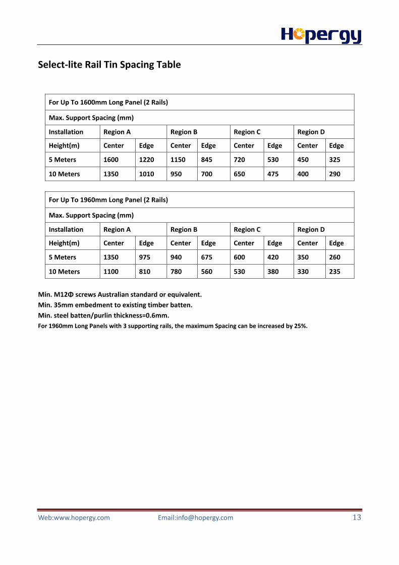
Select-lite Rail Tin Spacing Table
For Up To 1600mm Long Panel (2 Rails)
Max. Support Spacing (mm)
Installation Region A Region B Region C Region D
Height(m) Center Edge Center Edge Center Edge Center Edge
5 Meters 1600 1220 1150 845 720 530 450 325
10 Meters 1350 1010 950 700 650 475 400 290
For Up To 1960mm Long Panel (2 Rails)
Max. Support Spacing (mm)
Installation Region A Region B Region C Region D
Height(m) Center Edge Center Edge Center Edge Center Edge
5 Meters 1350 975 940 675 600 420 350 260
10 Meters 1100 810 780 560 530 380 330 235
Min. M12Φ screws Australian standard or equivalent. Min. 35mm embedment to existing timber batten. Min. steel batten/purlin thickness=0.6mm. For 1960mm Long Panels with 3 supporting rails, the maximum Spacing can be increased by 25%.

Web:www.hopergy.com Email:[email protected] 14
Select-lite Rail Tilt Spacing Table
1) For 10°-15°:
For Up To 1600mm Long Panel (2 Rails)
Max. Support Spacing (mm)
Installation Region A Region B Region C Region D
Height(m) Center Edge Center Edge Center Edge Center Edge
5 Meters 2000 1000 1400 700 675 338 417
10 Meters 1700 850 1200 600 610 305 376
15 Meters 1500 750 1050 525 532 328
20 Meters 1450 725 1000 500 479 300
For Up To 1960mm Long Panel (2 Rails)
Max. Support Spacing (mm)
Installation Region A Region B Region C Region D
Height(m) Center Edge Center Edge Center Edge Center Edge
5 Meters 1700 850 1150 575 552 340
10 Meters 1400 700 950 475 500 306
15 Meters 1250 625 880 440 435
20 Meters 1200 600 840 420 390
Min. 2-M12Φ screws Australian standard or equivalent. Min. 35mm embedment to existing timber batten. Min. steel batten/ purlin thickness=0.6mm. For 1960mm Long Panels with 3 supporting rails, the maximum Spacing can be increased by 25%.

Web:www.hopergy.com Email:[email protected] 15
2) For 15°-60°:
For Up To 1600mm Long Panel (2 Rails)
Max. Support Spacing (mm)
Installation Region A Region B Region C Region D
Height(m) Center Edge Center Edge Center Edge Center Edge
5 Meters 2100 1050 1450 725 900 450 560
10 Meters 1740 870 1200 600 820 410 500
15 Meters 1580 790 1090 545 720 360 440
20 Meters 1495 745 1030 515 640 320 395
For Up To 1960mm Long Panel (2 Rails)
Max. Support Spacing (mm)
Installation Region A Region B Region C Region D
Height(m) Center Edge Center Edge Center Edge Center Edge
5 Meters 1680 840 1160 580 720 360 440
10 Meters 1390 695 960 480 650 325 400
15 Meters 1260 630 870 435 570 350
20 Meters 1190 595 820 410 510 315
Min. 2-M12Φ screws Australian standard or equivalent. Min. 35mm embedment to existing timber batten. Min. steel batten/purlin thickness=0.6mm. For 1960mm Long Panels with 3 supporting rails, the maximum Spacing can be increased by 25%.

Web:www.hopergy.com Email:[email protected] 16
Hopergy KlipLok interface Clamp Spacing Table
Hopergy KlipLok Interface is a fantastic versatile exterior cladding clamp, the double-sided supporting walls ensure it has much better structural stability than other similar brackets on market.
Attention installer: For critical installations on metal roof by using KlipLok interface inspections by the required by a local qualified engineer prior to any installation, to ensure the existing metal roof is under suitable conditions, although we have provided the Max. Support Spacing as a guide only. Hopergy expresses no opinions as to the suitability of KlipLok interface for any specific application or project condition. Please ensure you use Hopergy KlipLok Interface responsibly. Assumption: The existing roofing is firmly/properly fixed to the existing roof battens.

Web:www.hopergy.com Email:[email protected] 17
Please use the following table to determine the KlipLok interface spacing for metal sheet roof installations for Australia A,B,C and D wind zones: Ⅰ. Max. Support Spacing (mm) for solar panels being fixed directly with mid clamps and end clamps.
Region A Region B Region C Region D Roof Type Center Edge Center Edge Center Edge Center Edge
KlipLok 406 1400 710 920 460 640
KlipLok 700 and Speed Deck Ultra
2000 1000 1320 660 950 470 580
KingKlip 700 1200 600 810 410 600
Ⅱ. Max. Support Spacing (mm) for composite application with tilt legs up to 15 degrees
Roof Type Region A Region B Region C
KlipLok 406 820 520
KlipLok 700 and Speed Deck Ultra
1200 760 520
KingKlip 700 550
Ⅲ. Max. Support Spacing (mm) for composite application with tilt legs up to 30 degrees
Roof Type Region A Region B Region C
KlipLok 406 560
KlipLok 700 and Speed Deck Ultra
820 530
KingKlip 700 480
Web:www.hopergy.com Email:[email protected] 18
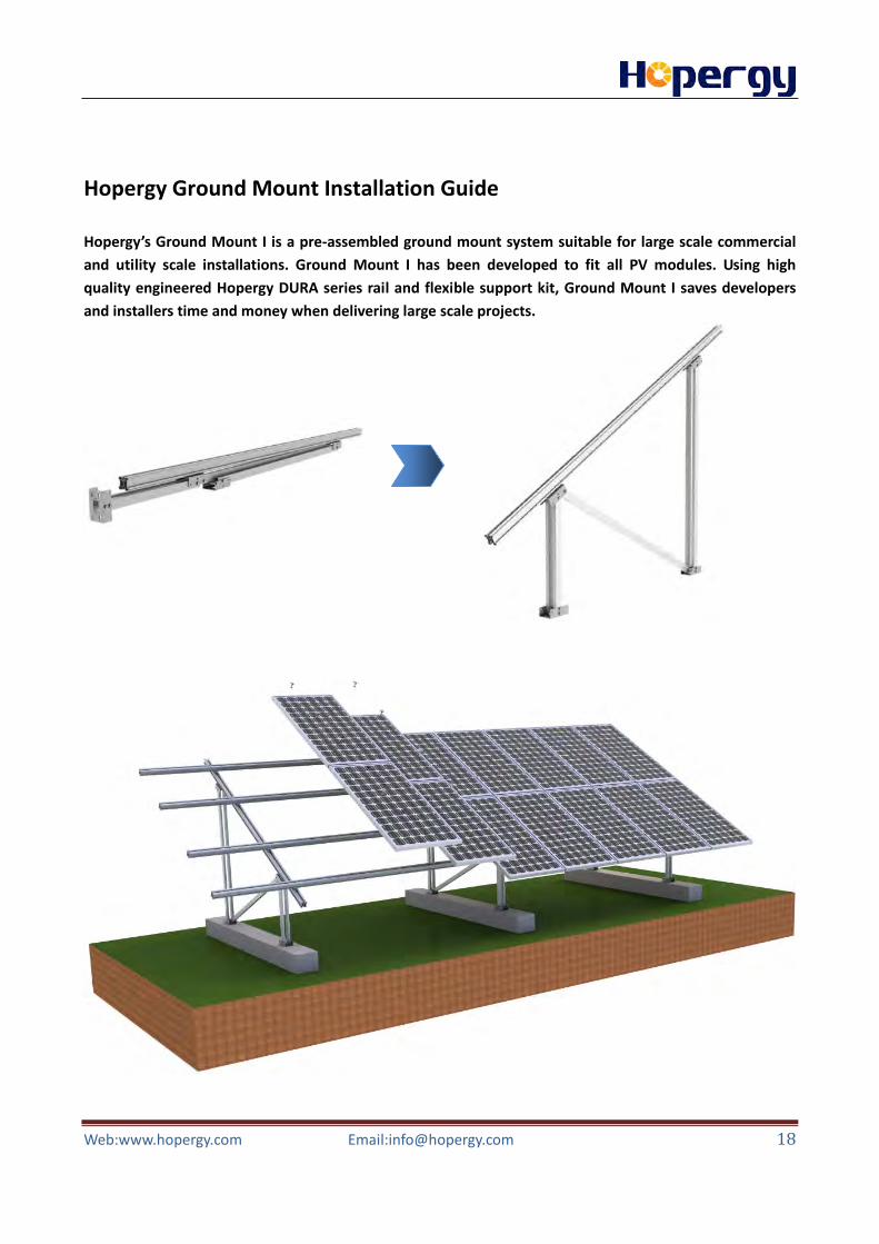
Hopergy Ground Mount Installation Guide
Hopergy’s Ground Mount I is a pre-assembled ground mount system suitable for large scale commercial and utility scale installations. Ground Mount I has been developed to fit all PV modules. Using high quality engineered Hopergy DURA series rail and flexible support kit, Ground Mount I saves developers and installers time and money when delivering large scale projects.

Web:www.hopergy.com Email:[email protected] 19
L=Solar Panel length. Hopergy Ground Mount I is compatible for panels up to 1800mm x1000mm). Maximum Spacing between Legs:
Wind Zone A B C D
Wind Speed(m/s) 43.4 53.0 65.2 81.7
D maximum spacing(mm) 2850 1880 1255 795
D

Web:www.hopergy.com Email:[email protected] 20
Hopergy Pole Mount Installation Guide
Hopergy Pole Mount is one optimized solution to mount 2, 3, 4, 6, 8 or 10 panels each pole with effective, flexible and durable single support post. Each pole system can be adjusted to five angles for being fixed at 10, 20, 30, 40 and 50 degree.

Web:www.hopergy.com Email:[email protected] 21
Planning the array layout 1. Array width = number of modules in the horizontal direction x module length + 11/16 in (18 mm). 2. Array height = number of modules in the vertical direction x (module width + 11/16 in (18 mm)) +1-1/4 in (32 mm) 3. Horizontal spacing of the rails attachment = approx. ½ of module length 4. Concrete footing under pole: a. 4 Panel-------Min 1200mmD*600mm SQ b. 6 Panel-------Min 1200mmD*600mm SQ c. 8 Panel-------Min 1300mmD*650mm SQ d. 10 Panel------Min 1300mmD*750mm SQ
1
2
3
4
L

Web:www.hopergy.com Email:[email protected] 23
Select-lite Series Rail System AS/NZS 1170.2 Certificate

Web:www.hopergy.com Email:[email protected] 24
Ground Mount PVGrid-I Certificate AS/NZS 1170.2 Certificate

Web:www.hopergy.com Email:[email protected] 25

Web:www.hopergy.com Email:[email protected] 26

Web:www.hopergy.com Email:[email protected] 27

Web:www.hopergy.com Email:[email protected] 28

Web:www.hopergy.com Email:[email protected] 30

Web:www.hopergy.com Email:[email protected] 31

Web:www.hopergy.com Email:[email protected] 32
Xiamen Hopergy Photovoltaic Technology Co., Ltd. Address: 1001 Unit, No.2366, Fangzhong Rd, Huli, Xiamen, 361015
P.R.China Tel:+86-592-5689685 Fax:+86-592-5638096
Email:[email protected] Website:www.hopergy.com