Honeywell's next generation PLCs Powerful, compact ... · PDF fileHoneywell's next generation...
46
Programmable Logic Controllers MasterLogic-200 Honeywell's next generation PLCs Powerful, compact, versatile, open network
Transcript of Honeywell's next generation PLCs Powerful, compact ... · PDF fileHoneywell's next generation...

Programmable Logic Controllers MasterLogic-200
Honeywell's next generation PLCs Powerful, compact, versatile, open network

Programmable Logic Controllers
MasterLogic-200
· Powerful & versatile
· Scalable & modular
· Compact pocket-size modules
· CPU redundancy, power supply redundancy, network redundancy
· Range of I/O modules-digital (source/sink,transistor/relay),analog (voltage/current)
· Special modules-High Speed Counter, Position Control, RTD, Thermocouple
· Open network-Profibus-DP, DeviceNet, Fast Ethernet, Modbus
· Dedicated peer-to-peer networking of PLCs
· Large I/O capacity and Remote I/O
Contents
Overview
Introduction
System Architecture
General Specifications
CPU Specifications
Highlights
Introduction Fast Ethernet(FEnet)
Serial Communication(Snet)
Profibus-DP(Pnet)
DeviceNet(Dnet)
Digital I/O Modules
Position Control Modules
Analog I/O Modules
Smart I/O(s)
Thermocouple Module
RTD Module
High Speed Counter Modules
Key Features Project Management
Online Functions
Maintenance & Troubleshooting
Monitoring
PLC Event History
Program Navigation & Editing
Program Ease
Simulation
System Requirements
SoftMaster-NM (Network setup &
diagnostics)
Special Interface with Experion PKS & Experion Vista
MasterLogic-50
Master Panel
HCiX Series
Product List
4 8
15
20
29
37 38 39
Overview
CPU & System configuration Network Input/Output Modules
Software Special Interface Other Related Products Product List

Overview
Introduction
Key Features
· Powerful & versatile processors - High speed i.e. (28ns/step, flash memory, hot-swapping)
· CPU redundancy - Bumpless switchover to standby CPU within 50ms when master CPU fails
· Power supply redundancy - For both CPU and I/O racks
· Network redundancy - Ring topology providing dual communication paths to I/O racks
· Redundant Link with MMI
· Peer-to-Peer communications - Dedicated Ethernet 100 Mbps
· Compact size - Less rack room & cabinet size space / reduced shipping & storage costs
· Open network protocols - Profibus™DP, DeviceNet™, Modbus …
· Open communication - Ethernet, Fiber-optic (100Mbps), Serial RS232/RS422
· IEC61131-3 standard programming - LD / SFC / ST language options
· Large I/O capacity
· Wide range I/O modules - Over 50 types: digital/analog, HSC, Position Control, High Speed Counter, Thermocouple
· Smart I/O (based on Profibus-DP, DeviceNet, Modbus)
· Engineer friendly software - Ease of configuration & trouble-shooting
· Integration with Experion PKS & Experion Vista - Diagnostics & SCADA via MLDP protocol
· Integration with third party MMI using Modbus protocol
· Self diagnostics - Network diagnostics, system logs, Auto scan, monitoring system
Size Innovation... Compact saves cabinet & floor space considerably
The smallest size
The module size is as small as
27x98x90 mm (pocket size). This
helps in reducing shipping/storage
cost and achieving cabinet/floor
space efficiency in today's world
where floor space is a premium &
costly resource.
4

Speed Innovation. . . Speed
& Power
High speed scan (e.g. estimated
15ms for typical large PLC
applications, say, 3500 I/Os and
program size of 400 Kbytes).
High Speed Processing
A state of the art processor in the CPU
makes it intrinsically powerful. All
program instructions are executed at
a high speed, thereby enabling even
complex instructions to be processed
very fast.
High-Speed dedicated I/O controller
The powerful processor as above (28ns/step) is well-supported by a
dedicated I/O bus controller to achieve overall fast scan cycles. This
dedicated I/O controller supplements the main processor in I/O
refresh and achieves high speed scan.
5

Network Innovation...Open
System Integration with Open Networks
The open communication standards
have continuously evolved and so
has MasterLogic-200 PLCs
capability to interface with them. In
addition to Modbus (Ethernet and
Serial), MasterLogic-200 supports
several open protocols in control
industry standards e.g. DeviceNet™,
Profibus™-DP etc.
Standards
Item
Transmission Speed
Physical Layer
Fast Ethernet 10/100 Mbps
IEEE802.3U-100 Base Tx (TP)
100 Base Fx (Fiber Optic)
Serial Comm 300 ~ 11.5 Kbps
RS232C / RS422 / 485
Profibus-DP 9.6k~12 Mbps
RS485
Device Net
125/250/500 Kbps
CAN
Distance
100m (Switch/Node, UTP/STP) Max 500m
2Km (Switch/Node, Fiber Optic) (RS422/485)
Max 1.2Km
100 / 250 / 500m
Max No of Nodes 64 32 126(32/segment) 64 (1 master + 63 slave)
HSL
MLDP
Peer-to-Peer
Experion Interface
-
-
Profibus-DP
-
DeviceNet
-
Service / Modbus slave Modbus TCP Slave Protocol
Modbus RTU / ASCII Slave
- -
P2P Modbus TCP/User Defined Protocol Master
Modbus/ User Defined
- -
Protocol Master
SoftMaster
No of Communication Modules per CPU
Network Diagnostics
6
-
Max 24 communication modules per CPU
(Max 12 HSL services & 8 P2P services per CPU)
Auto Scan, Ping Test, Frame Monitor, Link Monitor, Loop Back
-

Program Type
Allocation
INIT Program 1 max
Timer Interrupt Programs 32 max
Device Interrupt Programs 32 max
Scan Programs Balance: 256 minus sum of above
Total 256 max
Serial, ProfibusTM-DP, DeviceNet
Software Innovation... Engineer-Friendly
Integrated Programming & Engineering
SoftMaster software package provides integrated engineering environment from basic programming to different special
module settings as well as diagnosis. This package consists of SoftMaster(PLC programming) and SoftMaster-NM (Network
Management).
SoftMaster
· Engineer friendly software (multiple PLCs monitored in a single
window/project)
· Easy project documentation - programs, variable assignments, comments, etc
· Import/Export - configuration file can be imported or exported
· Two levels of remote connections
· Online editing & Debugging facility
· A special wizard for hot swapping of modules
· Various trouble-shooting and diagnostic features
· Common configuration tool for MasterLogic-50 and MasterLogic-200
SoftMaster-NM
· Slot assignment & configuration of all communication modules (Ethernet,
TM etc)
· Peer-to-Peer networking configuration
· Data transfer (transmission & receive) definitions
· Various network diagnostic features (e.g. protocol analysis)
Engineering & Programming Innovation... Versatile
Modular and interrupt driven program
MasterLogic-200 allows the engineer
to modularize the entire program into
several easily manageable
components. Also, several device
driven programs are supported e.g.
timer or process condition driven
interrupts. The table summarizes the
maximum numbers of programs that
are supported.
IEC61131-3 Standard Programming languages
MasterLogic-200 allows an engineer to program in any of the IEC61131-3 Standard Programming languages namely,
Ladder Logic, Sequential Function Charts and Structured Text.
7

CPU and System Configuration
Introduction
MasterLogic-200, Honeywell’s next
generation Programmable Logic
Controllers (PLC) adds power and
robustness to logic-interlock-
sequence batch control capabilities of
Experion network.
It is state of the art, compact yet
powerful & versatile, cost-effective
solution ideal for fast logic, sequential,
and batch control applications
The highlights of MasterLogic-200 PLC system are:
· Powerful & versatile CPU (high speed / memory, IEC programming etc)
· 32 bit processor for high speed execution
· Redundancy (CPU, Power, I/O network redundancy)
· High speed synchronization of program and data between primary and backup CPU via dedicated fibre-optic line
· Compact footprint (rack room, cabinet space saver, shipping costs saver)
· Modular options (power supply, range of I/O modules to suit your configuration)
· Flexibility in module assignment – any module can be installed in any slot of any base without any restrictions.
· Built-in twisted-pair of fibre-optic networks for local (100m) and remote I/O (2km) racks on ring topology
· Peer-to-Peer networks (dedicated Fast Ethernet on UTP/Fiber-optic)
· Simulation environment to test control strategies without hardware or process connections.
· Engineer friendly software (connection options, easy configuration and trouble-shooting)
· Diagnostics (system/error logs, system monitoring, network monitoring, ping test, frame monitor)
System Architecture
Redundancy options
MasterLogic-200 provides the control
system designer with various
redundancy architecture options that
fits the requirement.
Fully Redundant system
CPU Model: 2MLR-CPUH/T or 2MLR-CPUH/F provides a fully redundant system:
· Redundant CPU
· Redundant Power
· Redundant I/O cable (ring topology with dual paths)
8
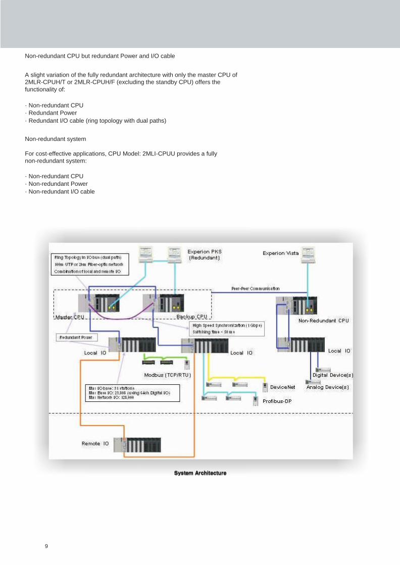
Non-redundant CPU but redundant Power and I/O cable
A slight variation of the fully redundant architecture with only the master CPU of
2MLR-CPUH/T or 2MLR-CPUH/F (excluding the standby CPU) offers the
functionality of:
· Non-redundant CPU
· Redundant Power
· Redundant I/O cable (ring topology with dual paths)
Non-redundant system
For cost-effective applications, CPU Model: 2MLI-CPUU provides a fully
non-redundant system:
· Non-redundant CPU
· Non-redundant Power
· Non-redundant I/O cable
System Architecture
9
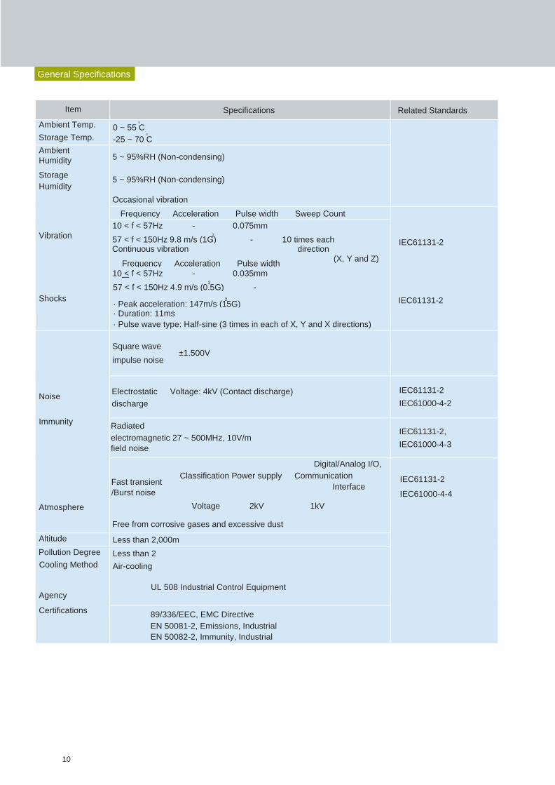
Item Specifications Related Standards
Ambient Temp.
Storage Temp.
0
0 ~ 55 C 0
-25 ~ 70 C
Ambient
Humidity
Storage
Humidity
Vibration
Shocks
5 ~ 95%RH (Non-condensing)
5 ~ 95%RH (Non-condensing)
Occasional vibration
Frequency Acceleration Pulse width Sweep Count
IEC61131-2
IEC61131-2
10 < f < 57Hz - 0.075mm 2
57 < f < 150Hz 9.8 m/s (1G) - 10 times each Continuous vibration direction
(X, Y and Z) Frequency Acceleration Pulse width
10 < f < 57Hz - 0.035mm 2
57 < f < 150Hz 4.9 m/s (0.5G) -
2
· Peak acceleration: 147m/s (15G) · Duration: 11ms
· Pulse wave type: Half-sine (3 times in each of X, Y and X directions)
Noise
Immunity
Atmosphere
Square wave ±1,500V
impulse noise
Electrostatic Voltage: 4kV (Contact discharge)
discharge
IEC61131-2
IEC61000-4-2
Radiated
electromagnetic 27 ~ 500MHz, 10V/m
field noise
IEC61131-2,
IEC61000-4-3
Digital/Analog I/O,
Classification Power supply Communication Fast transient
Interface /Burst noise
Voltage 2kV 1kV
Free from corrosive gases and excessive dust
IEC61131-2
IEC61000-4-4
Altitude Less than 2,000m
Pollution Degree
Cooling Method
Agency
Certifications
Less than 2
Air-cooling
UL 508 Industrial Control Equipment
89/336/EEC, EMC Directive
EN 50081-2, Emissions, Industrial
EN 50082-2, Immunity, Industrial
General Specifications
10
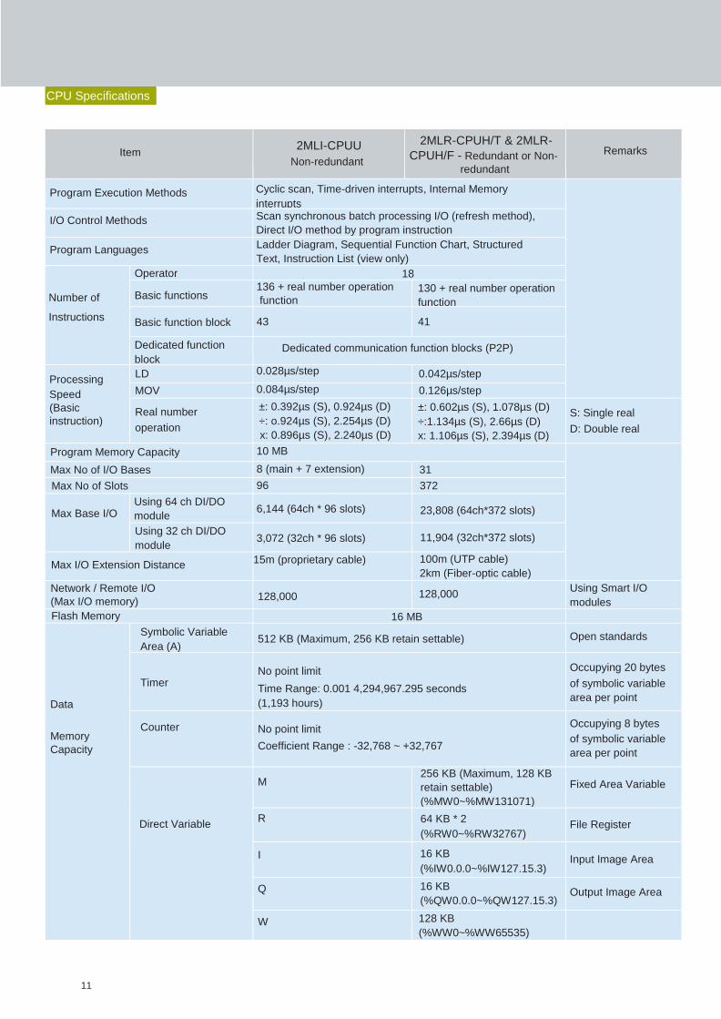
Item 2MLI-CPUU
Non-redundant
2MLR-CPUH/T & 2MLR-
CPUH/F - Redundant or Non-
redundant
Remarks
Program Execution Methods Cyclic scan, Time-driven interrupts, Internal Memory
interrupts
I/O Control Methods Scan synchronous batch processing I/O (refresh method),
Direct I/O method by program instruction
Program Languages Ladder Diagram, Sequential Function Chart, Structured
Text, Instruction List (view only)
Number of
Instructions
Operator 18
Basic functions 136 + real number operation
function 130 + real number operation
function
Basic function block 43 41
Dedicated function
block Dedicated communication function blocks (P2P)
Processing
Speed
(Basic
instruction)
LD 0.028µs/step 0.042µs/step
MOV 0.084µs/step 0.126µs/step
Real number
operation
±: 0.392µs (S), 0.924µs (D)
÷: o.924µs (S), 2.254µs (D)
x: 0.896µs (S), 2.240µs (D)
±: 0.602µs (S), 1.078µs (D)
÷:1.134µs (S), 2.66µs (D)
x: 1.106µs (S), 2.394µs (D)
S: Single real
D: Double real
Program Memory Capacity 10 MB
Max No of I/O Bases 8 (main + 7 extension) 31
Max No of Slots 96 372
Max Base I/O Using 64 ch DI/DO
module 6,144 (64ch * 96 slots) 23,808 (64ch*372 slots)
Using 32 ch DI/DO
module 3,072 (32ch * 96 slots) 11,904 (32ch*372 slots)
Max I/O Extension Distance 15m (proprietary cable) 100m (UTP cable)
2km (Fiber-optic cable)
Network / Remote I/O
(Max I/O memory) 128,000 128,000 Using Smart I/O
modules
Flash Memory 16 MB
Data
Memory
Capacity
Symbolic Variable
Area (A) 512 KB (Maximum, 256 KB retain settable) Open standards
Timer No point limit
Time Range: 0.001 4,294,967.295 seconds
(1,193 hours)
Occupying 20 bytes
of symbolic variable
area per point
Counter No point limit
Coefficient Range : -32,768 ~ +32,767
Occupying 8 bytes
of symbolic variable
area per point
Direct Variable
M 256 KB (Maximum, 128 KB
retain settable)
(%MW0~%MW131071)
Fixed Area Variable
R 64 KB * 2
(%RW0~%RW32767) File Register
I 16 KB
(%IW0.0.0~%IW127.15.3) Input Image Area
Q 16 KB
(%QW0.0.0~%QW127.15.3) Output Image Area
W 128 KB
(%WW0~%WW65535)
CPU Specifications
11
Item 2MLI-CPUU
Non-redundant
2MLR-CPUH/T & 2MLR-
CPUH/F - Redundant or
Non-redundant
Remarks
Data
Memory
Capacity
Flag
Variables
F 4KB System Flag
K 16KB PID Flag
L 22KB High Speed Link
Flag
N 42KB P2P Flag
U 8KB Analog refresh flag
as VAR_GLOBAL
Program
Type
Allocation
INIT Program 1 max
Timer Interrupt 32 max
Internal Device
Interrupt Programs 32 max
Scan Programs Balance: 256 minus sum of above
Total 256 max
CPU Operation Mode RUN, STOP, DEBUG
CPU Restart Mode Cold or warm restart
Self-diagnosis Watchdog timer, memory error, I/O error, battery error,
power error, communication error etc.
Built-in
Program Port
RS232C(1CH) Modbus slave
supported via
RS232C port USB (1CH) @ 12 Mbps
Note: Additional program connections via Ethernet &
serial communication module (locate or remote)
Data Storage Method at power off Retain area configuration via Basic parameters
Current Consumption 960mA
Weight 0.12kg
Switchover Time NA Less than 50 ms
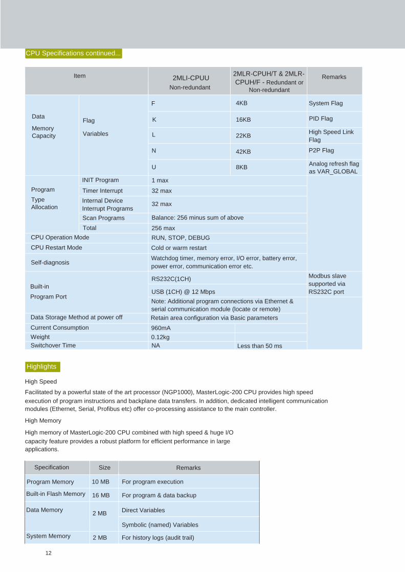
Specification Size Remarks
Program Memory 10 MB For program execution
Built-in Flash Memory 16 MB For program & data backup
Data Memory 2 MB
Direct Variables
Symbolic (named) Variables
System Memory 2 MB For history logs (audit trail)
CPU Specifications continued...
Highlights
High Speed
Facilitated by a powerful state of the art processor (NGP1000), MasterLogic-200 CPU provides high speed
execution of program instructions and backplane data transfers. In addition, dedicated intelligent communication
modules (Ethernet, Serial, Profibus etc) offer co-processing assistance to the main controller.
High Memory
High memory of MasterLogic-200 CPU combined with high speed & huge I/O
capacity feature provides a robust platform for efficient performance in large
applications.
12

Model: 2MLI-CPUU Qty Remarks
Max No of Bases 8 1 main base + 7 extension bases
Max No of Slots 96 12 slots * 8 base = 96 slots
Max No of Base I/O 6,144 points Using 64 ch DI/DO module 96 slots * 64 ch = 6,144
points
3,072 points Using 32 ch DI/DO module 96 slots * 32 ch = 3,072
points
Max No of Network & Remote I/O 128,000 points Using Smart I/O modules on Profibus-DP etc
Model: 2MLR-CPUH/T & 2MLR-CPUH/F Qty Remarks
Max No of Bases 31 On either Ethernet or Fiber-optic networks
Max No of Slots 372 12 slots * 31 base = 372 slots
Max No of Base I/O 23,808 points Using 64 ch DI/DO module 372 slots * 64 ch = 23,808
points
11,904 points Using 32 ch DI/DO module 372 slots * 32 ch = 11,904
points
Max No of Network & Remote I/O 128,000 points Using Smart I/O modules on Profibus etc
Retention Memory
Portions of data memory area provide (non-volatile) memory retention function.
· %R (File Register) memory area comprising 2 blocks of 64KB each serving
always as non-volatile memory for the engineers. The data stored here will be
retained even upon CPU power failure and during cold or warm restart options.
The data in this area can be cleared only by operating the CPU switch D.CLR
for > 3 sec or upon battery failure.
· The control engineer can selectively configure portion of %M memory areas for
memory retention in “Basic Parameters”. A max of 128KB can be configured
for memory retention in %M area.
· In addition to the above two, symbolic variables (named variables) occupying
512KB of data memory (local and global) can be individually configured for
memory retention during variable declaration phase.
Free Slot Assignment
This is good news to engineers
handling base/slot assignment.
MasterLogic-200 poses no restriction
whatsoever. Any module type i.e.
digital I/O, analog I/O, HSC (pulse
Without any restriction, any module
can also be installed in remote I/O
bases located far away (by using FO
network of 2MLR-CPUH/F or 2MLR-
CPUH/T).
input), RTD, Thermocouple, Position
Control and even communication
modules (i.e. Ethernet, Serial,
Profibus-DP, DeviceNet) can be freely
assigned to any base/slot irrespective
of base number, slot number.
Large I/O capacity
MasterLogic-200 accommodates a huge I/O capacity through base I/O and
remote I/O capabilities. I/O capacity details are tabulated below.
13

Function Type Functions / Function Blocks
Input Contacts NC/NO Contact , +Transition contacts
Coils Coil/Negated coils, Set/Reset coils (latch), +Transition sensing coils
Data Type Conversions Bool_to_*, Byte_to_*, Word_to_*, Int*_to_*, UInt*_to*, Real*_to_*, Time_to_*,
Date_to_*, String_to_*, BCD_to_*, *_to_BCD
Bit Functions AND, OR, NOT, XOR, XNR, SHL, SHR, ROL, ROR etc.
ARRAY Functions Move, Rotate, Compare, Fill, Average, Shift etc.
Comparison Functions GT, EQ, GE, LT, LE, NE
Timer On Delay, Off Delay, Pulse Timers...
Counter Count up, Count Down, Count Up/Down...
String Functions CONCAT, LEFT, RIGHT, MID, INSERT, DELETE, REPLACE...
Process Control Average, Delay, Limit, Rate, Summer, Totalizer, Analog_Selector, Function
Generator, Lead Lag,PID with auto tuning, Cascade Control, Ratio Control, Alarm,
Ramp, Latch, Valve, Data Conversion, Wave, Variance, Deadband etc
Stack Functions LIFO_***, FIFO_***...
Date & Time Functions Multiply, Subtract, Divide, Add functions on date and time variables
Mathematical Functions Exponential, Degree/Radian, ADD/MUL/DIV/SUB, ABS, MOD, Trigonometric (SIN,
COS, TAN...) SQRT, LOG...
Select Functions Max, Min, Multiplex...
System Control Functions SCON, DUTY, STOP, ESTOP, DIREC_IN/O, Watchdog reset, Master Clear,
Semaphore etc.
Position Control functions Functions for APM module
Programming Languages Remarks
LD (Ladder) Relay logic / interlocks
SFC (Sequential Function Chart) State / Transition diagrams for sequential/batch applications
ST (Structured Text) BASIC, PASCAL like programming language
FB (Function Block) To be used / embedded in other programming
languages e.g. LD, SFC, ST
IL (Instruction List) View only mode of LD instructions
High Speed Synchronization
IEC 61131-3 Standard Programming Languages
In redundant CPU systems, a
dedicated high speed 1 gigabit fiber-
optic link between primary and
seconday CPU ensures efficient
synchronization of data and program
memory areas. Upon failure of the
primary CPU, the control switches
over to the backup CPU bumplessly
in less than 50 ms.
MasterLogic-200 PLCs do not restrict
the control engineers with a solitary
ladder programming (LD) language.
Their work is made easier with a
choice of IEC standard programming
languages. Each of the IEC 61131-3
standard programming language is
designed for a specific application.
MasterLogic-200 empowers the
single CPU with modular programs,
each serving a specific requirement
typical to the industrial process
control situations.
control engineer with flexibility to mix
& match different languages in a
Function Block & Instr uction Librar y
Drastically reducing engineering time, a vast library of instructions & function blocks is pre-built and packaged with
MasterLogic-200 system. Here is an overview of the function block library available for the control engineer.
14
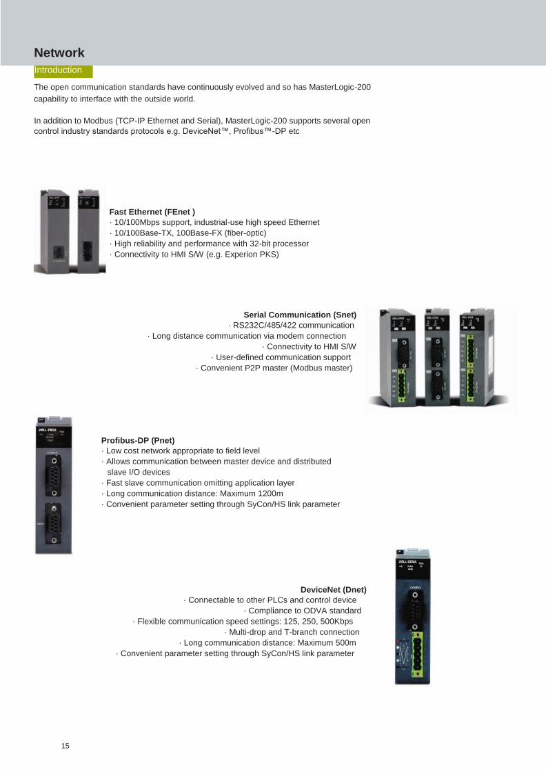
Network
Introduction
The open communication standards have continuously evolved and so has MasterLogic-200
capability to interface with the outside world.
In addition to Modbus (TCP-IP Ethernet and Serial), MasterLogic-200 supports several open
control industry standards protocols e.g. DeviceNet™, Profibus™-DP etc
Fast Ethernet (FEnet )
· 10/100Mbps support, industrial-use high speed Ethernet
· 10/100Base-TX, 100Base-FX (fiber-optic)
· High reliability and performance with 32-bit processor
· Connectivity to HMI S/W (e.g. Experion PKS)
Serial Communication (Snet)
· RS232C/485/422 communication
· Long distance communication via modem connection
· Connectivity to HMI S/W
· User-defined communication support
· Convenient P2P master (Modbus master)
Profibus-DP (Pnet)
· Low cost network appropriate to field level
· Allows communication between master device and distributed
slave I/O devices
· Fast slave communication omitting application layer
· Long communication distance: Maximum 1200m
· Convenient parameter setting through SyCon/HS link parameter
DeviceNet (Dnet)
· Connectable to other PLCs and control device
· Compliance to ODVA standard
· Flexible communication speed settings: 125, 250, 500Kbps
· Multi-drop and T-branch connection
· Long communication distance: Maximum 500m
· Convenient parameter setting through SyCon/HS link parameter
15
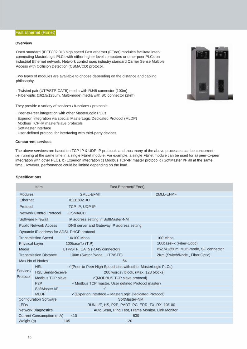
Item Fast Ethernet(FEnet)
Modules 2MLL-EFMT 2MLL-EFMF
Ethernet IEEE802.3U
Protocol TCP-IP, UDP-IP
Network Control Protocol CSMA/CD
Software Firewall IP address setting in SoftMaster-NM
Public Network Access DNS server and Gateway IP address setting
Dynamic IP address for ADSL DHCP protocol
Transmission Speed 10/100 Mbps 100 Mbps
Physical Layer 100baseTx (T.P) 100baseFx (Fiber-Optic)
Media UTP/STP, CAT5 (RJ45 connector) x62.5/125um, Multi-mode, SC connector
Transmission Distance 100m (Switch/Node , UTP/STP) 2Km (Switch/Node , Fiber Optic)
Max No of Nodes 64
Service /
Protocol
HSL(Peer-to-Peer High Speed Link with other MasterLogic PLCs)
HSL Send/Receive 200 words / block, (Max. 128 blocks)
Modbus TCP slave(MODBUS TCP slave protocol)
P2PModbus TCP master, User defined Protocol master)
SoftMaster I/F
MLDP(Experion Interface – MasterLogic Dedicated Protocol)
Configuration Software SoftMaster-NM
LEDs RUN, I/F, HS, P2P, PADT, PC, ERR, TX, RX, 10/100
Network Diagnostics Auto Scan, Ping Test, Frame Monitor, Link Monitor
Current Consumption (mA) 410 630
Weight (g) 105 120
Fast Ethernet (FEnet)
Overview
Open standard (IEEE802.3U) high speed Fast ethernet (FEnet) modules facilitate inter-
connecting MasterLogic PLCs with either higher level computers or other peer PLCs on
industrial Ethernet network. Network control uses industry standard Carrier Sense Multiple
Access with Collision Detection (CSMA/CD) protocol.
Two types of modules are available to choose depending on the distance and cabling
philosophy.
· Twisted pair (UTP/STP-CAT5) media with RJ45 connector (100m)
· Fiber-optic (x62.5/125um, Multi-mode) media with SC connector (2km)
They provide a variety of services / functions / protocols:
· Peer-to-Peer integration with other MasterLogic PLCs
· Experion integration via special MasterLogic Dedicated Protocol (MLDP)
· Modbus TCP-IP master/slave protocols
· SoftMaster interface
· User-defined protocol for interfacing with third-party devices
Concurrent services
The above services are based on TCP-IP & UDP-IP protocols and thus many of the above processes can be concurrent,
i.e. running at the same time in a single FEnet module. For example, a single FEnet module can be used for a) peer-to-peer
integration with other PLCs, b) Experion integration c) Modbus TCP-IP master protocol d) SoftMaster I/F all at the same
time. However, performance could be limited depending on the load.
Specifications
16

Item Serial Interface (Snet)
Modules 2MLL-C22A 2MLL-C42A 2MLL-CH2A
Interface Standard RS232C – 2 ch RS422/485 – 2 ch 1 ch–RS232C , 1 ch–RS422/485
Modem connection with remote
devices - (only on RS232C port)
Communication
Settings
Start Bit 1
Data Bits 7 or 8
Stop Bits 1 or 2
Parity Odd/Even/None
Baud rate Options: 300 / 600 / 1200 / 2400 / 4800 / 9600 / 19200 / 38400 / 57600 / 115200 bps
Synchronization Asynchronous
Transmission Distance 15m (extendable by modem /
phone line)
500m max RS232C - 15m (extendable
by modem)
RS422 - 500m max
Network Configuration 1:1 1:1, 1:N, N:M RS232C - 1:1
RS422 - 1:1, 1:N, N:M Station No Setting Setting range : 0-31 (Max. station no. available : 32 stations)
Service
/
Protocol
Modbus RTU / ASCII
slave
P2P (Modbus RTU/ASCII master, User defined Protocol master)
SoftMaster I/F
Configuration Software SoftMaster-NM
LEDs RUN, I/F, TX, RX, ERR
Network Diagnostics Auto Scan, Frame Monitor, Link Monitor, Loop Back
Current Consumption (mA) 310 300 310
Weight (g) 121 116 119
Serial Communication (Snet)
Overview
Like Ethernet, Serial Communication (Snet) modules add versatility and openness to
MasterLogic architecture. Open standard RS232C/RS422/RS485 modules facilitate
communication of MasterLogic PLCs with a wide range of serial devices i.e. RTU, panels,
weigh bridges, barcode readers, high level computers or even other PLCs.
Three types of modules are available to choose depending on the distance and partner
devices.
· Two ports of RS232C
· Two ports of RS422/485
· One RS232C port and one RS422/485 port
They provide a variety of services/functions/protocols:
· Modbus RTU/ASCII master/slave protocols
· SoftMaster interface
· User defined protocol for interfacing with third-party devices
Specifications
17

Product Item Profibus-DP (Pnet)
Module Type Master
Network Type Profibus-DP
Standard EN50170/DIN19245
Interface Rs485 (Electric)
Transmission Route Bus type
Modulation Type NRZ
MAC Local Token Ring
Max. Distance &
Transmission Speed
Distance (m) Transmission Speed (bps)
1,200 9.6K/19.2K/93.7K/187.5K
400 500K
200 1.5M
100 3M/6M/12M
Max. No of Stations per Profibus Network 126
Max. No of Stations per Segment 32 (including master & repeater)
Cable Used Electric-twist shielded pair cable
Max. Communication Size 7 Kbytes
Max. Size per Slave 244 bytes
Max. No of Profibus-DP Master Modules
per CPU 12
Configuration Tool SoftMaster-NM, SyCon
Current Cunsumption (mA) 550
Weight (g) 114
Profibus-DP (Pnet)
Overview
Pnet module is one of the communication modules of MasterLogic-200 PLC system. It uses
token ring topology to control the communication and configure the network. Pnet I/F module
uses a shielded Twisted Pair Copper Cable to control the fieldbus.
This module has the following characteristics:
· Conforms to the international standard of EN 50170
· Supports Auto Baud Rate Detect
· Supports Sync/Freeze mode
· Communication speed: 9.6K, 19.2K, 93.7K, 187.5K, 500K, 1.5M, 3M, 6M, 12Mbps
Specifications
18
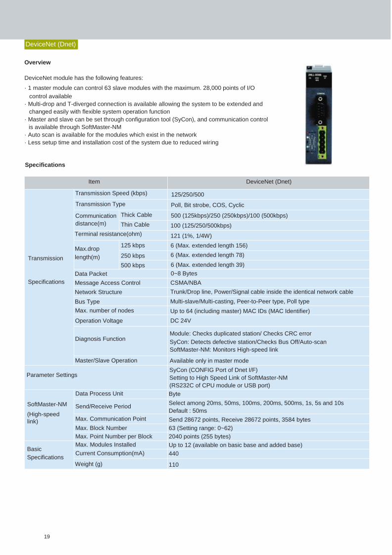
Item DeviceNet (Dnet)
Transmission
Specifications
Transmission Speed (kbps) 125/250/500
Transmission Type Poll, Bit strobe, COS, Cyclic
Communication
distance(m)
Thick Cable 500 (125kbps)/250 (250kbps)/100 (500kbps)
Thin Cable 100 (125/250/500kbps)
Terminal resistance(ohm) 121 (1%, 1/4W)
Max.drop
length(m)
125 kbps 6 (Max. extended length 156)
250 kbps 6 (Max. extended length 78)
500 kbps 6 (Max. extended length 39)
Data Packet 0~8 Bytes
Message Access Control CSMA/NBA
Network Structure Trunk/Drop line, Power/Signal cable inside the identical network cable
Bus Type Multi-slave/Multi-casting, Peer-to-Peer type, Poll type
Max. number of nodes Up to 64 (including master) MAC IDs (MAC Identifier)
Operation Voltage DC 24V
Diagnosis Function Module: Checks duplicated station/ Checks CRC error
SyCon: Detects defective station/Checks Bus Off/Auto-scan
SoftMaster-NM: Monitors High-speed link
Master/Slave Operation Available only in master mode
Parameter Settings SyCon (CONFIG Port of Dnet I/F)
Setting to High Speed Link of SoftMaster-NM
(RS232C of CPU module or USB port)
SoftMaster-NM
(High-speed
link)
Data Process Unit Byte
Send/Receive Period Select among 20ms, 50ms, 100ms, 200ms, 500ms, 1s, 5s and 10s
Default : 50ms
Max. Communication Point Send 28672 points, Receive 28672 points, 3584 bytes
Max. Block Number 63 (Setting range: 0~62)
Max. Point Number per Block 2040 points (255 bytes)
Basic
Specifications
Max. Modules Installed Up to 12 (available on basic base and added base)
Current Consumption(mA) 440
Weight (g) 110
DeviceNet (Dnet)
Overview
DeviceNet module has the following features:
· 1 master module can control 63 slave modules with the maximum. 28,000 points of I/O
control available
· Multi-drop and T-diverged connection is available allowing the system to be extended and
changed easily with flexible system operation function
· Master and slave can be set through configuration tool (SyCon), and communication control
is available through SoftMaster-NM
· Auto scan is available for the modules which exist in the network
· Less setup time and installation cost of the system due to reduced wiring
Specifications
19
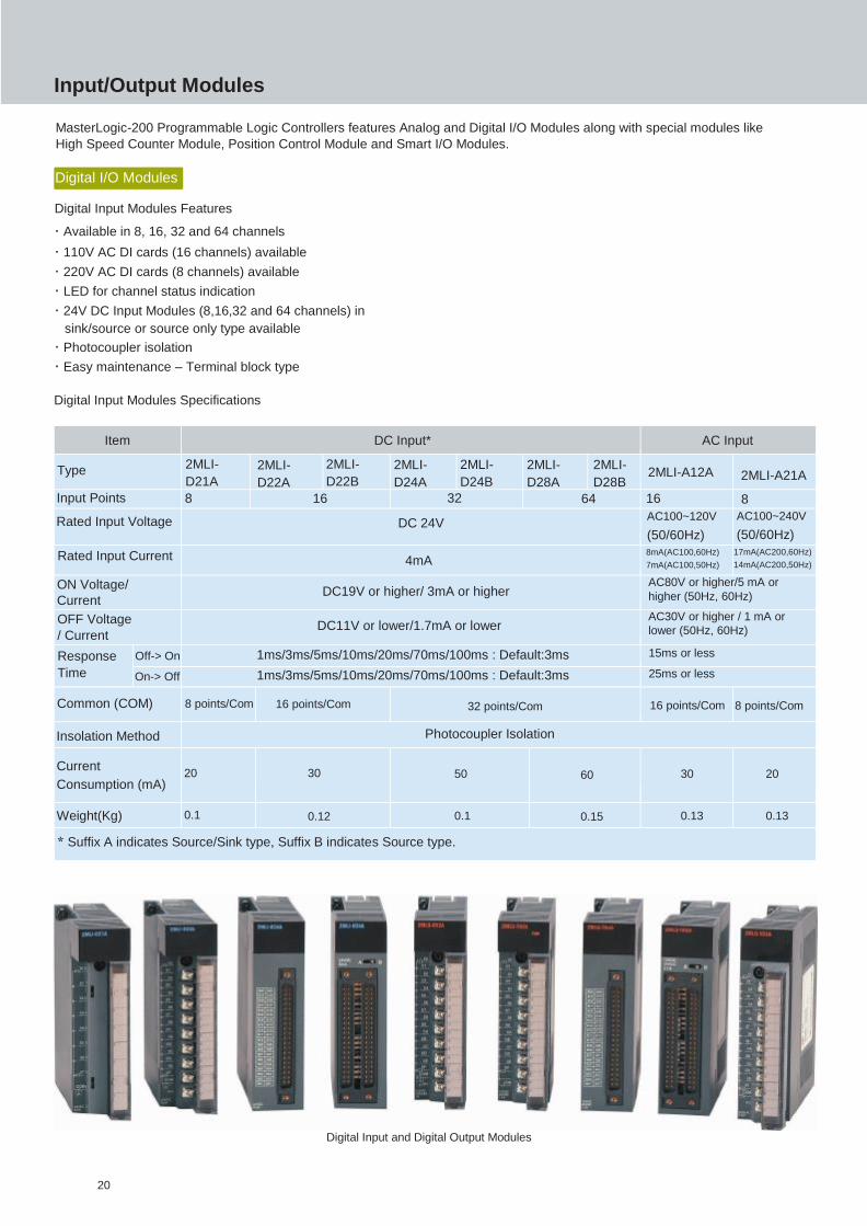
Item DC Input* AC Input
Type 2MLI-
D21A
2MLI-
D22A
2MLI-
D22B
2MLI-
D24A
2MLI-
D24B
2MLI-
D28A
2MLI-
D28B 2MLI-A12A 2MLI-A21A
Input Points 8 16 32 64 16 8
Rated Input Voltage DC 24V AC100~120V
(50/60Hz)
AC100~240V
(50/60Hz)
Rated Input Current 4mA 8mA(AC100,60Hz)
7mA(AC100,50Hz)
17mA(AC200,60Hz)
14mA(AC200,50Hz)
ON Voltage/
Current DC19V or higher/ 3mA or higher
AC80V or higher/5 mA or
higher (50Hz, 60Hz)
OFF Voltage
/ Current DC11V or lower/1.7mA or lower
AC30V or higher / 1 mA or
lower (50Hz, 60Hz)
Response
Time
Off-> On 1ms/3ms/5ms/10ms/20ms/70ms/100ms : Default:3ms 15ms or less
On-> Off 1ms/3ms/5ms/10ms/20ms/70ms/100ms : Default:3ms 25ms or less
Common (COM) 8 points/Com 16 points/Com 32 points/Com 16 points/Com 8 points/Com
Insolation Method Photocoupler Isolation
Current
Consumption (mA) 20 30 50 60 30 20
Weight(Kg) 0.1 0.12 0.1 0.15 0.13 0.13
* Suffix A indicates Source/Sink type, Suffix B indicates Source type.
Input/Output Modules
MasterLogic-200 Programmable Logic Controllers features Analog and Digital I/O Modules along with special modules like
High Speed Counter Module, Position Control Module and Smart I/O Modules.
Digital I/O Modules
Digital Input Modules Features
· Available in 8, 16, 32 and 64 channels
· 110V AC DI cards (16 channels) available
· 220V AC DI cards (8 channels) available
· LED for channel status indication
· 24V DC Input Modules (8,16,32 and 64 channels) in
sink/source or source only type available
· Photocoupler isolation
· Easy maintenance – Terminal block type
Digital Input Modules Specifications
Digital Input and Digital Output Modules
20

Item +
Relay Transistor* Triac
Type 2MLQ-
RY1A
2MLQ-
RY2A 2MLQ-
RY2B
2MLQ-
TR2A
2MLQ-
TR2B
2MLQ-
TR4A
2MLQ-
TR4B
2MLQ-
TR8A
2MLQ-
TR8B 2MLQ-SS2A
Output Points 8 16 16 32 64 16
Rated Load
Voltage/Current DC24V 2A (resistive load)
AC220V 2A DC12/24V
AC100-240V
(50/60Hz)
Response
Time
Off-> On 10ms or less 1ms or less 1ms or less
On-> Off 12ms or less 1ms or less 0.5 cycle
+1ms or less
Common (COM) 1point/Com 16 points/Com 16 points/Com 32 points/Com 16 points/Com
Isolation Method Relay Photocoupler Isolation
Current
Consumption (mA) 260 500 70 130 230 300
Weight(Kg) 0.13 0.17 0.19 0.11 0.12 0.1 0.15 0.2
* Suffix A indicates Sink type, Suffix B indicates Source type +
Suffix A indicates Sink type, Suffix B indicates Surge Absorber type
Digital Output Modules Features
· Available in 8, 16, 32 and 64 channels
· Relay, Traic and Transistor modules (sink or source type)
· LED for channel status indication
· Photocoupler isolation
· Easy maintenance – Terminal block type
· Thermal protection
Digital Output Modules Specifications
Position Control Modules
Position Control Modules Features
· High reliable position control with ASIC embedded controller
· High speed motor control (Max. Pulse Output: 1 Mbps)
· Arc/Linear interpolation, separate/synchronous operation
· Trapezoidal and S-curve acceleration/deceleration
· High speed processing of commands (4 ms)
· Encoder input support
· Monitoring, Tracking and Simulation available
· Easy to set positioning parameters (windows)
· Real time information and solution for each error
· Excel editing of parameters
· Self diagnostics
21
Position Control Modules
Item 2MLF-AV8A (Voltage Input Type) 2MLF-AC8A (Current Input Type)
Analog
Input
DC 1 ~ 5 V
DC 0 ~ 5 V
DC 0 ~ 10 V
DC -10 ~ 10 V
(Input Resistance: 1000 kOhm)
DC 4 ~ 20 mA
DC 0 ~ 20 mA
(Input Resistance 0.25 kOhm)
Digital
Output
(1) Voltage Type
(2) Current Type
16-bit binary value (data: 14 bits)
Format of digital output data can be individually set for each channel either through user program or
user-friendly GUI [I/O parameter] function in SoftMaster.
Accuracy 0
± 0.2% or less {when ambient temperature is 25(±5) C} 0
± 0.3% or less {when ambient temperature is 0~55 C}
Max.
Conversion
Speed
250 µs/channel
Input
Channels 8 channels/1module
Isolation
Method Photocoupler isolation between input terminal and PLC power
(no isolation between channels) Current
Consumption DC 5 V: 420mA
Weight(Kg) 0.14
Analog input
Digital output 4 ~20mA 0 ~20mA
Unsigned value 0 ~ 16000
Signed value -8000 ~ 8000
Precise value 4000 ~ 20000 0 ~ 20000
Percentile value 0 ~ 10000
Analog input
Digital output 1~5V 0~5V 0 ~ 10V -10 ~10V
Unsigned value 0 ~ 16000
Signed value -8000 ~ 8000
Precise value 1000 ~ 5000 0 ~ 5000 0 ~ 10000 -10000 ~ 10000
Percentile value 0 ~ 10000
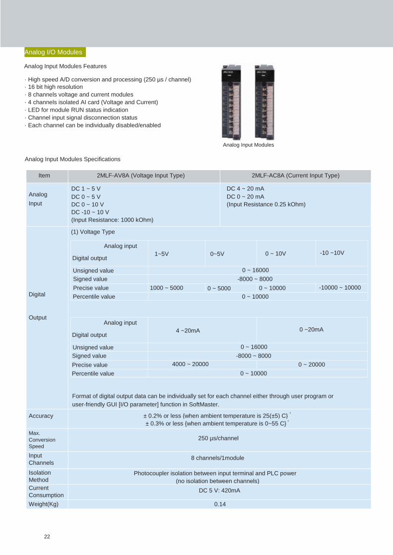
Analog I/O Modules
Analog Input Modules Features
· High speed A/D conversion and processing (250 µs / channel)
· 16 bit high resolution
· 8 channels voltage and current modules
· 4 channels isolated AI card (Voltage and Current)
· LED for module RUN status indication
· Channel input signal disconnection status
· Each channel can be individually disabled/enabled
Analog Input Modules
Analog Input Modules Specifications
22

Item 2MLF-AD4S (Voltage Input) 2MLF-AD4S (Current Input)
Analog
Input
Range
DC 1 ~ 5 V
DC 0 ~ 5 V
DC 0 ~ 10 V
DC -10 ~ 10 V
(Input Resistance: 1000 kOhm)
DC 4 ~ 20 mA
DC 0 ~ 20 mA
(Input Resistance 0.25 kOhm)
Digital
Output
(1) Voltage Type
(2) Current Type
16-bit binary value (-32768 ~ 32767)
Format of digital output data can be set through user program or [I/O Parameter setting] respectively
based on channels.
Accuracy 0
± 0.05% or less (when ambient temperature is 25 C)
Max. Conversion Speed
10ms / module
Input
Channels 4 channels/1module
Isolation
Specifications
Photocoupler isolation between input terminal and PLC power
(no isolation between channels)
Item Isolation method Isolation voltage immunity Isolation resistance
Between channels Transformer 500V AC, 50/60 Hz,
1min, Leakage
current less than
10mA
500V DC, over than
10000 kOhm Between input terminal
and PLC power
Photocoupler
Current
Consumption DC 5V: 610mA
Weight(Kg) 0.14
Analog input
Digital output 4 ~20mA 0 ~20mA
Signed value -32000 ~ 32000
Precise value 4000 ~ 20000 0 ~ 20000
Percentile value 0 ~ 10000
Analog input
Digital output 1~5V 0~5V 0 ~ 10V -10 ~10V
Signed value -32000 ~ 32000
Precise value 1000 ~ 5000 0 ~ 5000 0 ~ 10000 -10000 ~ 10000
Percentile value 0 ~ 10000
Analog Input Modules Features
23
2MLF-DV4A 2MLF-DV8A 2MLF-DC4A 2MLF-DC8A Item (Voltage Output Type) (Voltage Output Type) (Current Output Type) (Current Output Type)
DC 1 ~ 5V DC 4 ~ 20mA
DC 0 ~ 5V Load resistance: DC 0 ~ 20mA
Analog DC 0 ~ 10V 1 kOhm or more Load resistance:0.6 Load resistance:0.55
DC -10 ~ 10V Output kOhm or less kOhm or less
Output range can be selected through applicable program or parameters (for respective channels)
Signed 16-bit binary value (data: 14 bits)
Format of input data can be set through applicable program or parameters (for respective channels)
Analog output
1~5V 0~5V 0 ~ 10V -10 ~10V Digital input
Digital Unsigned value 0 ~ 16000
Input Signed value -8000 ~ 8000
Precise value 100 ~ 5000 0 ~ 5000 0 ~ 10000 -10000 ~ 10000
Percentile value 0 ~ 10000
Analog output
0 ~ 20mA 4 ~ 20mA Digital input
Unsigned value 0 ~ 16000
Signed value -8000 ~ 8000
Precise value 4000 ~ 20000 0 ~ 20000
Percentile value 0 ~ 10000 0
± 0.2% or less (when ambient temperature is 25 C) Accuracy
± 0.3% or less (when range is within operational temperature)
Max.
Conversion 250 µs/channel Speed
No. of Output 4 channels/
Channels 1 module
8 channels/
1 module
4 channels/
1 module
8 channels/
1 module
Isolation Photocoupler isolation between input terminal and PLC power
Method (no isolation between channels)
Current DC5V : 190 mA
Consumption DC24V : 140 mA
DC5V : 190 mA
DC24V : 180 mA
DC5V : 190 mA
DC24V : 210 mA
DC5V : 190 mA
DC24V : 300 mA
Weight(Kg) 0.15
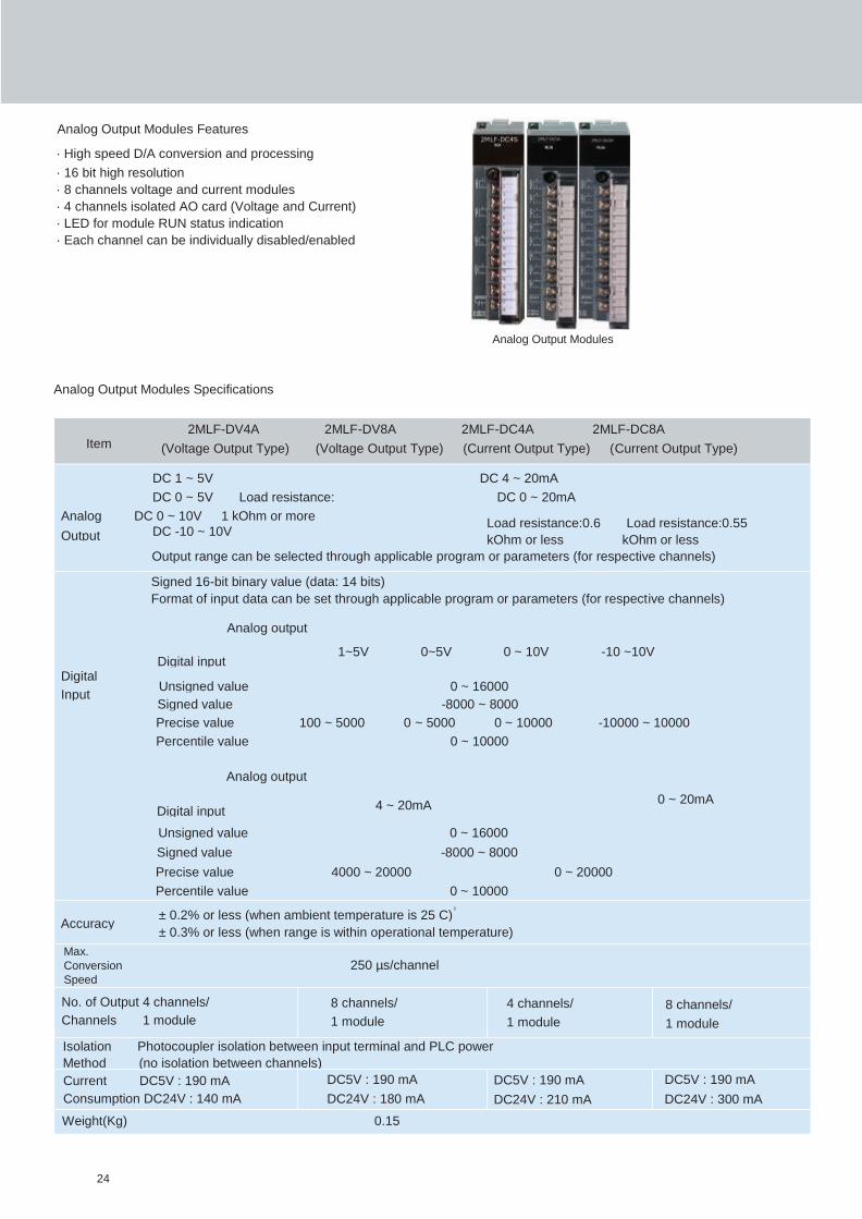
Analog Output Modules Features
· High speed D/A conversion and processing
· 16 bit high resolution
· 8 channels voltage and current modules
· 4 channels isolated AO card (Voltage and Current)
· LED for module RUN status indication
· Each channel can be individually disabled/enabled
Analog Output Modules
Analog Output Modules Specifications
24

Analog output
Digital input 1~5V 0~5V 0 ~ 10V -10 ~10V
Unsigned value 0 ~ 16000
Signed value -8000 ~ 8000
Precise value 1000 ~ 5000 0 ~ 5000 0 ~ 10000 -10000 ~ 10000
Percentile value 0 ~ 10000
± 0.1% or less (when ambient temperature is 25 C)
Analog Output Modules Specifications
Item
DC 4 ~ 20mA
2MLF-DC4S (Isolated Current Output Type)
Load resistance:0.6 kOhm or less
Analog
Output DC 0 ~ 20mA
Output range can be selected through applicable program or parameters (for respective channels)
Signed 16-bit binary value (data: 14 bits)
Format of input data can be set through applicable program or parameters (for respective channels)
Digital
Input
Analog output
Digital input
Unsigned value
Signed value
Precise value
Percentile value
4 ~ 20mA 4000 ~ 20000
0 ~ 20mA
0 ~ 16000
-8000 ~ 8000
0 ~ 20000
0 ~ 10000
Accuracy
Max.
Conversion
Speed
No. of Output
Channels
Isolation
Method
0
10ms/4 channels 4 channels / 1 module
Photocoupler isolation between input terminal and PLC power
(no isolation between channels)
Current
Consumption
Weight(Kg)
Internal
External
0.15
DC5V : 200mA
DC24V : 220 mA
Smart I/O(s)
Smart I/O Modules Features
· Remote I/O application
· Reduction of wiring costs and hassles
· Easy to install and implement
· Real time monitoring & control of distributed I/O
· Various I/O (DC/TR/Relay) modules with the unit of 16/32 points
· Supports open networks like DeviceNet, Profibus-DP, Modbus (RS422/485)
25
Smart I/Os
Item 2MLF-TC4S
No of Input Channels 4 Channels
Type of Input Sensor K,J,E,T,B,R,S,N,C JIS C1602-1995 , ITS-90
Range of Input
Temperature
K -250 ~ 1350 ºC
J -200 ~ 1200 ºC
E -250 ~ 1000 ºC
T -250 ~ 400 ºC
B 400 ~ 1800 ºC
R -50 ~ 1750 ºC
S -50 ~ 1750 ºC
N -270 ~ 1300 ºC
C 0 ~ 2300 ºC
Digital Output Temp. display(unit of 0.1) Displaying down to one decimal place (0.1 ºC)
Scaling display (user-defined scaling) 0 ~ 65535 -32768 ~32767
Conversion Velocity 40ms / channel
Isolation Method Channel to Channel Isolation
Terminal to PLC power Isolation (Photocoupler)
Function Averaging function Time average (320~64000 ms)
Frequency average (2~64000 times)
Moving average (2~100)
Alarm function
Process alarm
Gradient alarm
Disconnection detection
Filter function Digital filter (160~64000 ms)
Max./Min. display Display Max./Min.
Current Consumption 5V: 610mA
Weight (Kg) 0.15
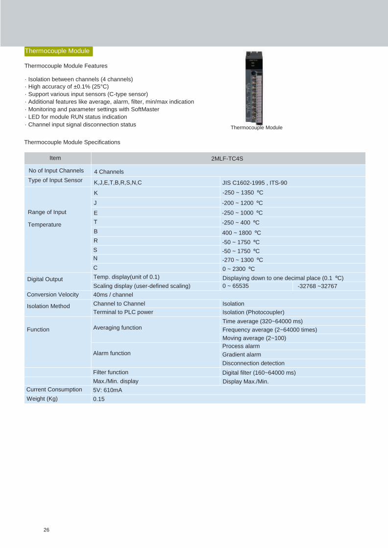
Thermocouple Module
Thermocouple Module Features
· Isolation between channels (4 channels)
· High accuracy of ±0.1% (25°C)
· Support various input sensors (C-type sensor)
· Additional features like average, alarm, filter, min/max indication
· Monitoring and parameter settings with SoftMaster
· LED for module RUN status indication
· Channel input signal disconnection status
Thermocouple Module Specifications
26
Thermocouple Module
Item 2MLF-RD4A
No. of Input Channels 4 Channels
Pt100
Input Sensor Type Jpt100 JIS C1604-1997
JIS C1604-1981, KS C1603-1991
Pt100
Temperature Input Range Jpt100
-200.0 ~ 850.0 ºC
-200.0 ~ 640.0 ºC
Temperature display (unit: 0.1)
Digital output Scaling display (Customize)
Pt100 -200.0 ~ 850.0 ºC / -328.0 ~ 1562.0 ºF
Jpt100 -200.0 ~ 640.0 ºC/ -328.0 ~ 1184.0 ºF
0 ~ 65535
-32768 ~ 32767
Conversion Speed 40ms / channel
Channel to Channel
Isolation Terminal to PLC Power
Non-isolation
Photocoupler
Average
Function
Alarm
Filtering
Time average (320-64000ms)
Counting average (2-64000 count)
Moving average (2-100 samples)
Process alarm
Input changing rate alarm
Disconnection detection
Digital filter (160-64000 ms)
Current Consumption 5V: 450mA
Weight(Kg) 0.15
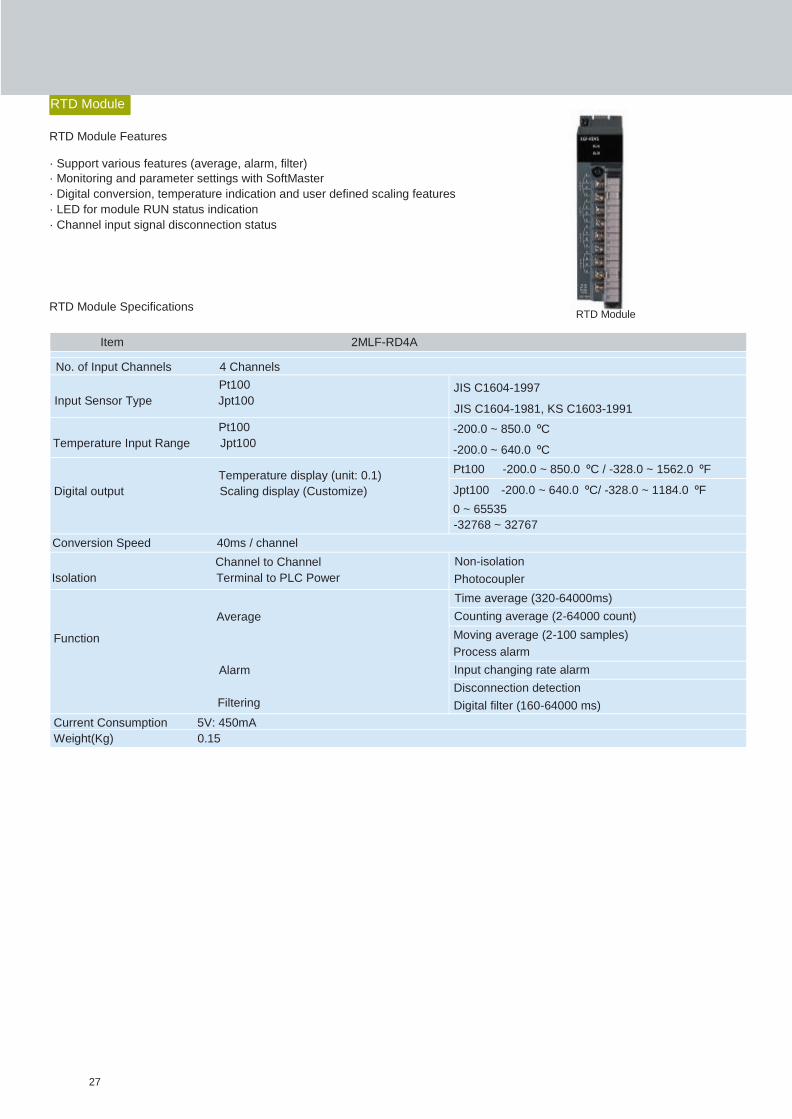
RTD Module
RTD Module Features
· Support various features (average, alarm, filter)
· Monitoring and parameter settings with SoftMaster
· Digital conversion, temperature indication and user defined scaling features
· LED for module RUN status indication
· Channel input signal disconnection status
RTD Module Specifications
27
RTD Module
Item 2MLF-H02A 2MLF-HD2A
Count
Input
Signal
Signal A-phase, B-phase
Input Type Voltage Input (Open Collector) Differential Input (Line Drive)
Signal Level DC 5/12/24V RS422A Line Drive/HTL Level line drive
Maximum Coefficient 200kpps
Speed 500kpps(HTL Input is 250 kpps)
Number of Channels 2
Coefficient Range Signed 32-bit (-2,147,483,648 ~ 2,147,483,647)
Count Type Linear Count with Carry/Borrow when 32-bit range is exceeded, maximum/minimum count
(program setting) Ring Count (repeated count within setting range)
1-phase input
Input Mode 2-phase input
(program setting) CW/CCW input
Signal Type Voltage
Count
Up/Count
Down
Setting
1-phase Increase or Decrease of count by B-phase input
input Increase or Decrease of count by program
2-phase input Automatic setting by difference in phase
A-phase input: increasing operation
CW/CCW B-phase input: decreasing operation
Multiplica
-tion
Function
1-phase input 1/2 multiplication (program setting)
2-phase input 1/2/4 multiplication (program setting)
CW/CCW 1-multiplication
Current Consumption 270mA 330mA
Weight (Kg) 0.09
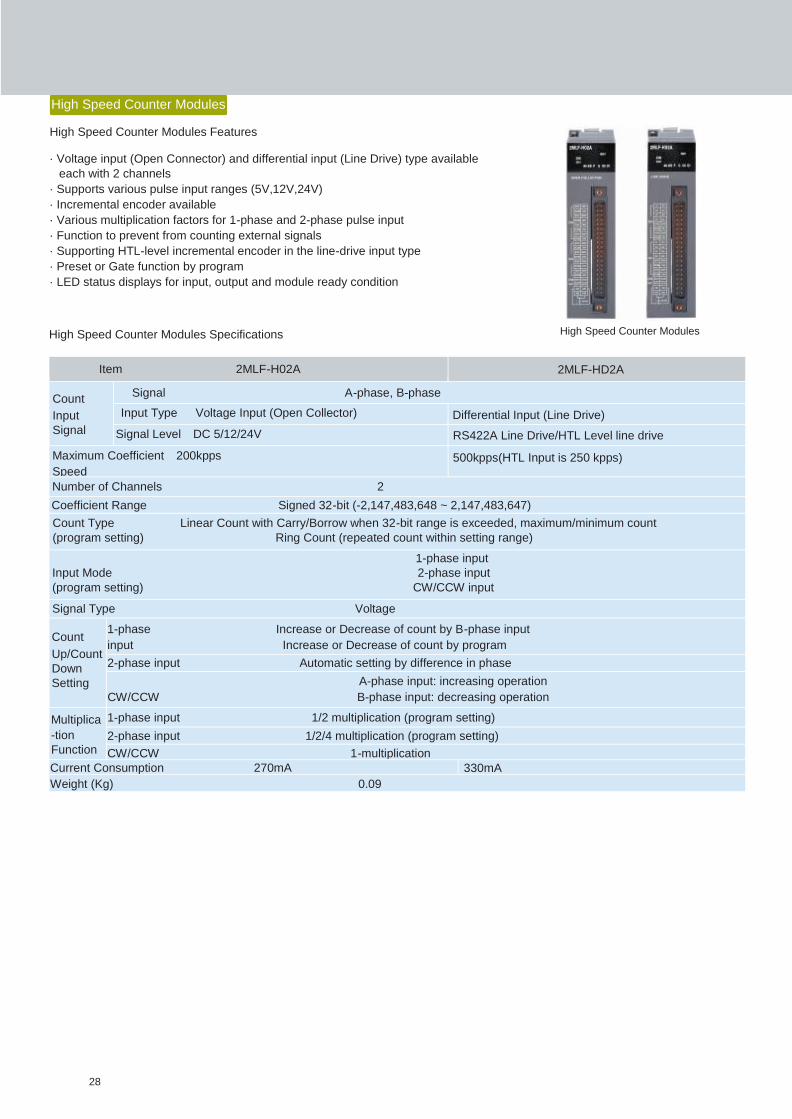
High Speed Counter Modules
High Speed Counter Modules Features
· Voltage input (Open Connector) and differential input (Line Drive) type available
each with 2 channels
· Supports various pulse input ranges (5V,12V,24V)
· Incremental encoder available
· Various multiplication factors for 1-phase and 2-phase pulse input
· Function to prevent from counting external signals
· Supporting HTL-level incremental encoder in the line-drive input type
· Preset or Gate function by program
· LED status displays for input, output and module ready condition
High Speed Counter Modules Specifications
28
High Speed Counter Modules

Item 2MLF-SOEA
No. of input point 32 points
Insulation method Photo-Coupler Insulation
Memory size 1Mbit
Rated input voltage DC24V
Rated input current Approx. 4mA / points
Voltage range DC20.4 ~ 28.8V(5% and lower ripple rate)
On voltage/On current DC19V and higher / 3 mA and higher
Off voltage/ Off current DC11V and lower/ 1.7 mA and lower
Input resistance Approx. 5.6 kΩ
Response time(ms) Off On 100us+Input filter time(User setting: 0~100ms)
On Off 150us+Input filter time(User setting: 0~100ms)
Clock Synchronization CPU RTC or RS-422 by IRIG-B format
Withstand voltage AC560V rms/3 Cycle (altitude 2000m)
Insulation resistance 10MΩ and higher (DC500V)
COMM method 32point / COM
Current consumption 0.4 A (MAX)
Operation display LED On with Input On
External connection method 40point connector
Size(mm) 27x98x90
Weight 0.2 kg
Event Input Module(SOE)
Event Input Module(SOE) Features
· SOE : Sequence of Events Recorder
· I/O information collection to analyze the control
System in Generation and Transformer
· Event collection in every 1ms
· Max 300 sets data available
· Data retain by built-in memory
· Max installable module : 16 sets
· Event monitoring of history through SOE viewer
Event Input Modules Specifications
SOE Viewer
29
Event Input Modules(SOE)
Software
Key Features
SoftMaster provides the engineer with an integrated PLC
engineering environment - all in one window such as ladder
programming, configuration/setup of CPU or communication
modules, debugging, monitoring, trouble-shooting,
documentation and maintenance etc.Integrated PLC engineering environment:
SoftMaster is Microsoft Windows based software with
standard and very user-friendly GUI features like:
· Drag and drop
· Short-cut keys & toolbar icons
· Microsoft excel-like cell input
· Auto-fill, export/import
· Undo and Redo options
· Context sensitive menu enabling/disabling
· Customizable views, colors, fonts
· Find, Replace
· Environment to install : Win XP to Win7, Win10 (Recommended to install on Windows 7, x86/x64)
Project Management
· SoftMaster helps managing multiple PLCs through a single window.
One project file (.xgp) can encompass multiple PLCs of the site.
Also, this file will serve as a central storage of all details related to
each PLC like:
· Scan programs & interrupt programs
· I/O module configuration & special module settings
· Communication module settings
· Variable names, comments, descriptions
· Flash memory / data retention settings
· Other PLC settings
· There is no limit on number of PLCs that can be included in one
project file.
· Project files can be compared automatically.
· Export/Import entire PLC data into/from a single file (.plc) or
selectively on each category (variable/comments -.cmt, programs -
prg, basic PLC configuration -.bsp, I/O module settings -.iop etc.)
· Flexible documentation: Print the entire project documentation at
the click of a button e.g. customizable cover page, header/footer,
variable/comments, normal scan programs, task interrupt
programs, basic PLC configuration, I/O module configuration etc
for all PLCs in the project.
30

Online Functions
· Connection to PLC: SoftMaster supports 4 methods of connection:
· RS232C port of computer and built-in RS232C port of CPU (direct) or Snet module in the PLC.
· USB port of computer and the built-in USB port of CPU
· Ethernet port of computer and Ethernet port of FEnet module
· Modem via RS232C and telephone connections (as in first option)
· Two levels of remote connection: This facility helps when your computer is not directly connected to a PLC as it can be
programmed to through another PLC which is connected to the computer
· CPU mode RUN/STOP/DEBUG can be switched remotely from the program. In DEBUG mode, multiple breakpoints can
be set in the program and run step by step for critical trouble-shooting. Breakpoints also can be automatic based on a
device condition
· READ/WRITE with the online PLC can be done selectively
· Compare with PLC: The project opened in computer can be compared with the project in online PLC for an automatic
report on similarities and differences
· Configuring the use of flash memory on whether the program can be backed on to flash memory after every download or
online editing
· Online editing of ladder program while it is being executed
Maintenance and Troubleshooting
Force I/O: I/O refresh memory can be forced manually to
any specific value for maintenance, trouble-shooting or
simulation purposes. Both input and output (bit or word
data) image area can be forced to a value.
Force I/O
Skip I/O: For any maintenance purpose, an entire I/O base
including all its slots or any selective slot (module) can be
set for I/O skip through the software. The CPU ignores that
I/O base or the particular slot during its operation.
Skip I/O
31
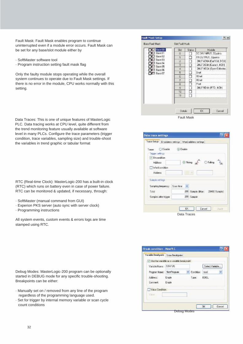
Fault Mask: Fault Mask enables program to continue
uninterrupted even if a module error occurs. Fault Mask can
be set for any base/slot module either by
· SoftMaster software tool
· Program instruction setting fault mask flag
Only the faulty module stops operating while the overall
system continues to operate due to Fault Mask settings. If
there is no error in the module, CPU works normally with this
setting.
Data Traces: This is one of unique features of MasterLogic
Fault Mask
PLC. Data tracing works at CPU level, quite different from
the trend monitoring feature usually available at software
level in many PLCs. Configure the trace parameters (trigger
condition, trace variables, sampling size) and trouble-shoot
the variables in trend graphic or tabular format
RTC (Real-time Clock): MasterLogic-200 has a built-in clock
(RTC) which runs on battery even in case of power failure.
RTC can be monitored & updated, if necessary, through:
· SoftMaster (manual command from GUI)
· Experion PKS server (auto sync with server clock)
· Programming instructions Data Traces
All system events, custom events & errors logs are time
stamped using RTC.
Debug Modes: MasterLogic-200 program can be optionally
started in DEBUG mode for any specific trouble-shooting.
Breakpoints can be either:
· Manually set on / removed from any line of the program
regardless of the programming language used.
· Set for trigger by internal memory variable or scan cycle
count conditions
Debug Modes
32

Module exchange wizard: A software wizard guides the
engineer through the steps involved in exchanging a module
safely during CPU run mode. Errors detected, if any are
displayed to the user.
In addition to the wizard, the engineer can also exchange the
module (hot-swapping) by setting the M-XCHG dip switch in
CPU to ON.
Module exchange wizard
User-defined Event Recording (SOE): Any bit data device
(digital I/O, memory flags etc) can be configured for event
recording when the device condition turns on (rising) or off
(falling) or any change of state. SoftMaster allows an event list
to be configured and managed with add/edit/delete functions.
Each event can be prioritized into three categories: a) alarm
message b) warning message c) information
The events can be recorded at millisecond resolution. CPU also
maintains the event history in its memory. Custom Event
This functionality enables an engineer to program the PLC for
Sequential Event Recording (SER) or Sequence of Events
(SOE) functionality.
Monitoring
Ladder Monitor: Ladder monitor for online status of program
execution. Force I/O setting can also be done from here directly.
Ladder Monitoring
System Monitoring: This tool empowers the PLC support
engineer to connect to any PLC and monitor the overall system
status in a single window i.e. base, slot and I/O module
configuration, device status of I/O channels etc. Each I/O base
can be individually traversed back and forth for monitoring.
System Monitoring
Variable Monitoring: Variable monitoring related devices (I/O
addresses and other data memory) can be grouped and
monitored together in a single window for context sensitive
trouble-shooting.
These variables are not restricted to one PLC but can be spread
across multiple PLCs.
Variable Monitoring
33

Event type Description Buffer Size in CPU
Error Log Any error occurring in system - error code, timestamp, error details 2048 events
System Log Operation history of key system events
2048 events with timestamp
Mode Change Log CPU mode changes, 1024 events
RUN/STOP/DEBUG with timestamp Power Shutdown Log
Power ON/OFF, failure events with 1024 events
timestamp
Special Module Monitoring: Special modules such as Analog
Input/Output modules, High Speed Counter (HSC) modules
are monitored through this tool.
Special Module Monitoring
Trend Monitoring: Various analog and digital devices (data
type such as BIT, WORD, DWORD, REAL etc) from I/O and
other memory devices can be trended together on a single
window for context sensitive trouble-shooting. Sampling
speed, X and Y-axis range (time and data value) also can be
adjusted to the needs.
Trend Monitor
PLC Event History
MasterLogic-200 CPU stores four types of event history for
monitoring, diagnostics and trouble-shooting purposes. The
event details are stored in CPU until they are reviewed and
deleted from SoftMaster software.
Event History
Program Navigation and Editing
SoftMaster has numerous ways to assist the engineer in navigation through the programs.
· Variable name and comment/description for each device address
· Find and replace via variable name, device address and comment
· GOTO commands, bookmarks
· Breakpoints in online debug mode
34

Program Ease
User defined function blocks: SoftMaster allows the creation of password protected user defined
function blocks. A user can build the custom logic & strategies in these function blocks using
configurable input and output parameters & data types. These user defined function blocks can
be password protected for security and copyright purposes.
User defined data types: SoftMaster allows the creation of user defined data types in addition to
the standard IEC data types.
Symbolic (Named) Variables with auto memory allocation: A significant amount of data memory,
as high as 512KB, is allocated for symbolic variables in MasterLogic-200. This is equivalent to
50% of the total data memory, thus intensifying the utilization of auto memory allocation.
The control engineers can simply build named variables circumventing the hassles of manual
memory allocation and derive the convenience of letting the CPU automatically allocate memory
according to the data types. This eliminates human lapses involved in duplicate assignment,
unused memory etc.
Three-dimensional arrays: Array variables are extremely useful to a programmer to store a series
of related data items. For example, an array variable Tank_Level[0..9] can be used to store level
values of a max of 10 similar tanks.
35

System Configuration Minimum
Processor 2.0 GHz Pentium IV or faster
RAM 128 MB
Video Resolution 1024 x 768
Hard Drive 10 GB
Operating System Windows XP + Service Pack 2
External Interface RS232 Serial or USB
Simulation
Simulation allows an engineer to program without PLC or debug program by using input
condition setting or module simulation function.
The following features are supported by the simulation environment:
Program simulation: The program written in LD/SFC/ST can be simulated. Online editing and
debugging is supported by the simulation environment.
PLC online function: The program monitoring and online diagnostic functions (e.g. system
monitoring / device monitoring) can be used during simulation.
Module simulation: Digital I/O module, Analog I/O module, High Speed Counter module,
Temperature Control module, Position Control module can be simulated.
I/O input condition setting: Simulation environment supports setting device value or channel
value of the I/O module as an input condition.
System Requirements
36

Product FEnet Snet Pnet Dnet
Auto Scan · · · ·
Link Monitor · · · ·
Frame Monitor · · - ·
SoftMaster-NM (Network setup & diagnostics)
Features
· Manages all communication modules (FEnet, Snet, Pnet, Dnet )
· Easy setup of network configuration and associated communication
parameters (IP address, serial port etc)
· Configuration of HSL (high speed link) service (send data, receive data, packet
size etc)
· Configuration of P2P (point to point) service (channel, block settings etc)
· Extended monitoring and diagnostics of communication modules
· Simple and easy connection using MLDP (MasterLogic dedicated protocol)
and other driver (Modbus)
· Various built-in diagnostics functions
· Ability to define and communicate using user-defined protocols
Various network diagnostics and monitoring
· Auto Scan: Searching and displaying each node connected to network
· Link Monitor: Monitoring status of high-speed link communication of
each station
· Frame Monitor: Collecting and displaying sending/receiving frame in
real time
37

Special Interface
Special Interface with Experion PKS & Experion Vista
MasterLogic-200 PLCs are tightly integrated with Experion PKS architecture. They directly reside on Experion PKS network
averting the need for any intermediate gateway equipment.
· The interface is simple to configure MasterLogic PLC channels, controllers and points just like any other SCADA interface
· For efficient communication optimization, the integration supports both synchronous (timer based subscription of real time
data) and asynchronous (report by exception) communication methods
· All PLC clocks are synchronized with Experion PKS server clock
· PLC system alarms and events (e.g. battery fail, CPU stop/reset/error) are automatically cascaded to Experion PKS
summary page
· PLC system status (graphical display) can be monitored from all Experion PKS stations
· Integration with third party MMI using Modbus protocol
MasterLogic-200 configuration status
38
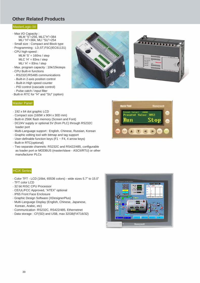
Other Related Products
MasterLogic-50
· Max I/O Capacity : MLM “S”=256, MLC”H”=384 MLI “H”=384, MLI “SU”=254
· Small size : Compact and Block type
· Programming : LD,ST,FSC(IEC61131)
· CPU high-speed :
MLM ‘S’ = 160ns / step
MLC ‘H’ = 83ns / step
MLI ‘H’ = 83ns / step
· Max. program capacity : 10k/15ksteps
· CPU Built-in functions
- RS232C/RS485 communications
- Built-in 2-axis position control
- Built-in High speed counter
- PID control (cascade control)
- Pulse catch / input filter · Built-in RTC for “H” and “SU” (option)
Master Panel
· 192 x 64 dot graphic LCD
· Compact size (160W x 90H x 30D mm)
· Built-in 256K flash memory (Screen and Font)
· DC24V supply or optional 5V (from PLC) through RS232C
loader port
· Multi-Language support : English, Chinese, Russian, Korean
· Graphic editing tool with bitmap and tag support
· User-definable function keys (F1 ~ F4, 4 arrow keys)
· Built-in RTC(optional)
· Two separate channels: RS232C and RS422/485, configurable
as loader port or MODBUS (master/slave - ASCII/RTU) or other
manufacturer PLCs
HCiX Series
· Color TFT - LCD (16bit, 65536 colors) - wide sizes 5.7” to 15.0”
· TFT color LCD
· 32 bit RISC CPU Processor
· CE/UL/FCC Approved, “ATEX” optional
· IP65 Front Face Enclosure
· Graphic Design Software (XDesignerPlus)
· Multi-Language Display (English, Chinese, Japanese,
Korean, Arabic, etc)
· Communication :RS232C, RS422/485, Ethernetnet
· Data storage : CF(SD) and USB, max 32GB(FAT16/32)
39

Product Model Description
Main CPU Base
(only for
2MLI-CPUU)
2MLB-M04A For 4 modules installation
2MLB-M06A For 6 modules installation
2MLB-M08A For 8 modules installation
2MLB-M12A For 12 modules installation
Expansion I/O Base
(only for
2MLI-CPUU)
2MLB-E04A For 4 modules installation
2MLB-E06A For 6 modules installation
2MLB-E08A For 8 modules installation
2MLB-E12A For 12 modules installation
Power module
(only for
2MLI-CPUU)
2MLP-ACF1
AC 100V~240V input,
DC 5V: 3A,
DC 24V: 0.6A
2MLP-ACF2 AC 100V~240V input
DC 5V: 6A
2MLP-AC23 AC 100V~240V input
DC 5V: 8.5A
2MLP-DC42 DC 24V Input
DC 5V: 6A
Expansion I/O cable
(only for
2MLI-CPUU)
2MLC-E041 Length: 0.4m
2MLC-E061 Length: 0.6m
2MLC-E121 Length: 1.2m
2MLC-E301 Length: 3.0m
2MLC-E501 Length: 5.0m
2MLC-E102 Length: 10.0m
2MLC-E152 Length: 15.0m
Product List
CPU Module
Product Model Description
CPU Module
2MLI-CPUU High speed CPU module ( Non- Redundant system)
(Max. I/O point: 6,144 points)
2MLI-CPUH/T High speed CPU module ( Non- Redundant or Redundant system),
Master, TP/CAT5 (Max. I/O point: 23,808 points)
2MLI-CPUH/F High speed CPU module ( Non- Redundant system or Redundant system),
Master, Fiber Optic (Max. I/O point: 23,808 points)
I/O Base, Cables (2MLI-CPUU)
40
Product Model Description
FEnet Modules 2MLL-EFMF · Fast Ethernet (multi-mode fiber-optic media), Master
· 10/100 Mbps support
2MLL-EFMT · Fast Ethernet (CAT 5 media), Master
· 10/100 Mbps support
Snet modules
2MLL-C22A · Serial communication
· RS232C, 2 channels
2MLL-C42A · Serial communication
· Rs422 (485), 2 channels
2MLL-CH2A · Serial communication
· RS232C 1 Channel / RS422 (485) 1 Channel
Profibus-DP Module 2MLL-PMEA Profibus-DP Master Module
DeviceNet Module 2MLL-DMEA DeviceNet Master Module
Product Model Description
Main CPU Base
(for 2MLR-CPUH/T, 2MLR-
CPUH/F)
2MLR-M06P CPU base for 6 module installation
Expansion I/O Base
(for 2MLR-CPUH/T,
2MLR-CPUH/F)
2MLR-E12P I/O Base for 12 module installation
Power modules
I/O interface modules
(for 2MLR-CPUH/T,
2MLR-CPUH/F)
2MLR-AC13 8.5A, Voltage (110V)
2MLR-AC23 8.5A, Voltage (220V)
2MLR-AC12 5.5A, Voltage (110V)
2MLR-AC22
2MLR-DBSF
5.5A, Voltage (220V)
I/O Interface Module, Fiber Optic
2MLR-DBST
2MLR-DBSH
I/O Interface Module, TP/CAT5
I/O Interface Module, Hybrid (Fiber Optic & TP/CAT5)
I/O Base, I/O Interface Modules, Cables (2MLR-CPUH/T & 2MLR-CPUH/F)
Communication Modules
41

Product Model Description
Digital Input
Modules
2MLI-D21A DC 24V Input, 8 points (Current source / sink input)
2MLI-D22A DC 24V Input, 16 points (Current source / sink input)
2MLI-D24A DC 24V Input, 32 points (Current source / sink input)
2MLI-D28A DC 24V Input, 64 points (Current source / sink input)
2MLI-D22B DC 24V Input, 16 points (Current source input)
2MLI-D24B DC 24V Input, 32 points (Current source input)
2MLI-D28B DC 24V Input, 64 points (Current source input)
2MLI-A12A AC 110V input, 16 points
2MLI-A21A AC 220V input, 8 points
Digital Output
Modules
2MLQ-RY1A Relay output, 8 points (for 2A, single COM.)
2MLQ-RY2A Relay output, 16 points (for 2A)
2MLQ-RY2B Relay output, 16 points (for 2A), Varistor included
2MLQ-TR2A Transistor output 16 points (for 0.5A, Sink output)
2MLQ-TR4A Transistor output 32 points (for 0.1A, Sink output)
2MLQ-TR8A Transistor output 64 points (for 0.1A, Sink output)
2MLQ-TR2B Transistor output 16 points (for 0.5A, Source output)
2MLQ-TR4B Transistor output 32 points (for 0.1A, Source output)
2MLQ-TR8B Transistor output 64 points (for 0.1A, Source output)
2MLQ-SS2A Triac output, 16 points (for 0.6A)
Digital I/O Modules
42
Product Model Description
Analog Input
Modules
2MLF-AV8A · Voltage Input: 8 channels
· DC 1 ~ 5V / 0 ~ 5V / 0 ~ 10V / -10 ~ +10V
2MLF-AC8A
· Current Input: 8 channels
· DC 4 ~ 20mA / 0 ~ 20mA
2MLF-AD8A · Voltage/Current Input: 8 channels
2MLF-AD4S · Voltage/Current Input: 4 channels
· Isolation between channels
Analog Output
Modules
2MLF-DV4A · Voltage Output: 4 channels
· DC 1 ~ 5V / 0 ~ 5V / 0 ~10V / -10 ~ +10V
2MLF-DC4A · Current Output: 4 channels
· DC 4 ~ 20mA / 0 ~ 20mA
2MLF-DC4S · Current Output: 4 channels
· Isolation between channels
2MLF-DV8A · Voltage Output: 8 channels
· DC 1 ~ 5V / 0 ~ 5V / 0 ~ 10V / -10 ~ +10V
2MLF-DC8A · Current Output: 8 channels
· DC 4 ~ 20mA / 0 ~ 20mA
Thermocouple Input
Module 2MLF-TC4S
· Temperature (T/C) Input, 4 channels
· Isolation between channels
RTD Input
Module 2MLF-RD4A Temperature (RTD) Input, 4 channels
High speed
Counter
Module
2MLF-HO2A · Voltage Input type (Open Collector type)
· 200 kHz, 2 channels
2MLF-HD2A · Differential Input type (Line Driver type)
· 500 kHz, 2 channels
Position Control
Module
2MLF-PO3A Pulse output (Open Collector type), 3 axes
2MLF-PO2A Pulse output (Open Collector type), 2 axes
2MLF-PO1A Pulse output (Open Collector type), 1 axis
2MLF-PD3A Pulse output (Line Driver type), 3 axes
2MLF-PD2A Pulse output (Line Driver type), 2 axes
2MLF-PD1A Pulse output (Line Driver type), 1 axis
Analog I/O, HSC, Position Control Modules
43

Product Model Description
Profibus-DP
Smart IOs
MPL-AC8C Analog Current Input, 8 Channels
MPL-AV8C Analog Voltage Input, 8 Channels
MPL-D22C DC Input 16 Points
MPL-D24C DC Input 32 Points
MPL-DT4C1 DC Input 16 Points / TR Output 16 Points(0.5A, Sink)
MPL-DC4C Analog Current Output, 4 Channels
MPL-DT4C DC Input 16Points / TR Output 16 Points(0.5A, Source)
MPL-DV4C Analog Voltage Output, 4 Channels
MPL-RY2C Relay Output 16 Points
MPL-TR2C TR Output 16 Points (0.5A, Source)
MPL-TR2C1 TR Output 16 Points (0.5A, Sink)
MPL-TR4C TR Output 32 Points (0.5A, Source)
MPL-TR4C1 TR Output 32 Points (0.5A, Sink)
DeviceNet
Smart IOs
MDL-D22C DC Input 16 Points
MDL-D24C DC Input 32 Points
MDL-DT4C DC Input 16 Points / TR Output 16Points (0.5A, Source)
MDL-DT4C1 DC Input 16 Points / TR Output 16Points (0.5A, Sink)
MDL-RY2C Relay Output 16 Points
MDL-TR2C TR Output 16 Points (0.5A, Source)
MDL-TR2C1 TR Output 16 Points (0.5A, Sink)
MDL-TR4C TR Output 32 Points (0.5A, Source)
MDL-TR4C1 TR Output 32 Points (0.5A, Sink)
Modbus
Smart IOs
MSL-D22A DC Input 16 Points
MSL-D24A DC Input 32 Points
MSL-TR2A TR Output 16 Points (0.1A, Sink)
MSL-TR4A TR Output 32 Points (0.1A, Sink)
MSL-RY2A Relay Output 16 Points
MSL-DT4A DC Input 16 Points / TR Output 16 Points (0.1A, Sink)
Smart I/O Modules
44

Product Model Description
SoftMaster SoftMaster Programming tool for MasterLogic PLC
Experion
Interface Driver
SSS-MLEP-250 Driver for 250 points integration with Experion PKS
SSS-MLEP-500 Driver for 500 points integration with Experion PKS
SSS-MLEP-1000 Driver for 1000 points integration with Experion PKS
SSS-MLEP-1500 Driver for 1500 points integration with Experion PKS
SSS-MLEP-2000 Driver for 2000 points integration with Experion PKS
SSS-MLEP-3000 Driver for 3000 points integration with Experion PKS
SSS-MLEP-XXXX Driver for unlimited points integration with Experion PKS (limited
by performance constraints only)
Product Model Description
Terminator 2MLT-TERA Must use for base expansion
Dummy module 2MLT-DMMA Dust protection module for unused slot
Master Panel
MXP10BKB/DC 4.1”, Mono, RS-232C,RS-422/485
MXP10BKB/DC 4.1”, Mono, RS-232C,RS-422/485, RTC
MasterPanel-Editor Master Panel Editor Software Package
HCiX Series Local HMI
HCiX05-TE-FD-NC 5.7” Color TFT LCD (16bit color), 24Vdc power, CF card/USB Communication : RS232C,RS422/485, Ethernet
HCiX08 –TE-FD-NC 8.4” Color TFT LCD (16bit color), 24Vdc power, CF card/USB Communication : RS232C,RS422/485, Ethernet, (Profibus-DP, option)
HCiX10–TE-FD-NC HCiX10-TE-FA-NC
10.4” Color TFT LCD (16bit color), 24Vdc/100~240Vac power, CF card/USB, Communication : RS232C,RS422/485, Ethernet, (Profibus-DP, option)
HCiX12–TE-FD-NC HCiX12-TE-FA-NC
12.1” Color TFT LCD (16bit color), 24Vdc/100~240Vac power, CF card/USB, Communication : RS232C,RS422/485, Ethernet, (Profibus-DP, option)
HCiX15–TE-FD-NC HCiX15-TE-FA-NC
15.0” Color TFT LCD (16bit color), 24Vdc/100~240Vac power, CF card/USB, Communication : RS232C,RS422/485, Ethernet, (Profibus-DP, option)
HCiW series Economic, Local HMI
HCiW07 –TE-FD-NC HCiW07 –TV-FD-NC
7” wide Color TFT LCD (16bit color), 24Vdc power, SD card/USB Communication : RS232C,RS422/485, Ethernet
HCiW10 –TE-FD-NC HCiW10 –TV-FD-NC
10.2” wide Color TFT LCD (16bit color), 24Vdc power, CF card/USB Communication : RS232C,RS422/485, Ethernet
XDesignerPlus for HCi series is available.
Product Model Description
USB cable USB-301A Programming cable for USB port
RS232C cable KIC-50A Programming cable for RS232C port (CPU, Snet module)
Software Environment
Programming Cables
Others
45

Warranty/Remedy
Honeywell warrants goods of its manufacture as being
Distributor:
free of defective materials and faulty workmanship.
Contact your local sales office for warranty information.
If warranted goods are returned to Honeywell during
the period of coverage, Honeywell will repair or replace
without charge those items it finds defective.
The foregoing is Buyer’s remedy and it is in lieu of all
other warranties, experessed or implied, including
those of merchantability and fitness for a particular
purpose.
Specifications may change without notice. The
information we supply is believed to be accurate and
reliable as of this printing, however we assume no
responsibility for its use. While we provide application
assistance personally, through our literature and the
Honeywell website, its up to the customer to determine
the suitability of the product in the application.
For further information, a quotation or demonstration please contact your nearest Honeywell
office or local distributor.
· Australia
· Canada
· China Beijing
Tel: (61) 2-9353-4500
Tel: (1-800) 461-0013
Tel: (86-10) 8458-3280
· Latin America
· Malaysia
· New Zealand
Tel: (1-305) 805-8188
Tel: (603) 7958-4988
Tel: (64-9) 623-5050
· China Shanghai Tel: (86-21) 6237-0237 · Philippines Tel: (63-2) 633-2830
· Indonesia
· India
· Japan
· Korea
Tel: (62) 21-535-8833
Tel: (91) 20-5603-9400
Tel: (81) 3-6730-7140
Tel: (82) 2-799-6114
· Singapore
· Thailand
· Thaiwan R.O.C
Tel: (65) 6355-2828
Tel: (662) 693-3099
Tel: (886) 2-2245-1000
Email: [email protected]
Jan 2015
© 2007 Honeywell International Inc. All rights reserved.