Honeywell Sensing and Control Manual Switches
142
Manual Switches For application help: call 1-800-537-6945. Honeywell 1 MICRO SWITCH Sensing and Control 1 Pushbuttons Pushbutton Panels Toggles/Rockers Manuals Pushbutton panels. Low profile SLP pushbutton panels feature standard matrices and custom arrays tailored to your requirements. They use a con- ductive rubber technology for operator feedback. Plus full-face LED light- ing and legends, and a variety of button sizes and colors. Manual switches. Designed by industrial designers to achieve a balance between harmonious appearance and ergonomics, AML Advanced Manual Line has pushbuttons, paddles,and rockers; with LED, incandes- cent, and neon illumination. Plus matching indicators and LED annuncia- tors. A smaller cousin, MML Miniature Manual Line, offers many AML fea- tures in a space-saving size. Pushbuttons. A wide array of different pushbutton families, many with lighted display and matching indicators. Includes Series 2, an easily as- sembled modular design with many color display/control options; low- cost DM pushbuttons and compact PB unlighted pushbuttons. Toggles/Rockers. NT/TL, TS, TW and AT toggles, and NR/TP rockers fea- ture various degrees of sealing, choice of many circuitry combinations, and 2 or 3-position operation. Typical Applications .......................... 2 Index by Product Type ....................... 3 Selection Guides .......................... 4-7 Catalog Listings/Order Guide .............. 8-161 Panel Design Guide ........................ 162 Catalog Listing - Page Number Index ......... 170 Selection Courtesy of Steven Engineering , Inc. ! 230 Ryan Way, South San Francisco, CA 94080-6370 ! Main Office: (650) 588-9200 ! Outside Local Area: (800) 258-9200 ! www.stevenengineering.com
Transcript of Honeywell Sensing and Control Manual Switches

Manual Switches
For application help: call 1-800-537-6945. Honeywell 1 MICRO SWITCH Sensing and Control 1
Pushbuttons Pushbutton Panels
Toggles/Rockers
Manuals
Pushbutton panels. Low profile SLP pushbutton panels feature standardmatrices and custom arrays tailored to your requirements. They use a con-ductive rubber technology for operator feedback. Plus full-face LED light-ing and legends, and a variety of button sizes and colors.
Manual switches. Designed by industrial designers to achieve a balancebetween harmonious appearance and ergonomics, AML AdvancedManual Line has pushbuttons, paddles,and rockers; with LED, incandes-cent, and neon illumination. Plus matching indicators and LED annuncia-tors. A smaller cousin, MML Miniature Manual Line, offers many AML fea-tures in a space-saving size.
Pushbuttons. A wide array of different pushbutton families, many withlighted display and matching indicators. Includes Series 2, an easily as-sembled modular design with many color display/control options; low-cost DM pushbuttons and compact PB unlighted pushbuttons.
Toggles/Rockers. NT/TL, TS, TW and AT toggles, and NR/TP rockers fea-ture various degrees of sealing, choice of many circuitry combinations,and 2 or 3-position operation.
Typical Applications . . . . . . . . . . . . . . . . . . . . . . . . . . 2Index by Product Type . . . . . . . . . . . . . . . . . . . . . . . 3Selection Guides . . . . . . . . . . . . . . . . . . . . . . . . . . 4-7Catalog Listings/Order Guide . . . . . . . . . . . . . . 8-161Panel Design Guide . . . . . . . . . . . . . . . . . . . . . . . . 162Catalog Listing - Page Number Index . . . . . . . . . 170
Selectio
n
Courtesy of Steven Engineering , Inc. ! 230 Ryan Way, South San Francisco, CA 94080-6370 ! Main Office: (650) 588-9200 ! Outside Local Area: (800) 258-9200 ! www.stevenengineering.com

Manual Switches AML SeriesAdvanced Manual Line
18 Honeywell 1 MICRO SWITCH Sensing and Control For application help: call 1-800-537-6945.
IN FRONT OF THE PANELCoordinated, attractive appearance.AML features innovations designed by in-dustrial designers to achieve the best bal-ance of human factors and aesthetic ap-pearance. Operator height, bezel size,and the compatibility of square and rect-angular shapes blend with other compo-nents to harmonize your panel. There’sno visual clutter to distract from man/machine communication.
This comprehensive line of lighted andunlighted manual controls features:1 Pushbuttons for high and
intermediate frequency functions;1 Rocker and paddle switches, with 2 or
3 positions, for less frequent controlfunctions;
1 Plus lighted indicators andannunciators which complementAML’s universal appeal.
Various controls can be matched withtheir functions to accommodate the mostnatural and efficient habit pattern reflex.Keylock operated switches can be usedto assure ‘‘authorized personnel only’’access.
Display flexibility. AML offers a choice offive legend sizes, four button heights, fullor split section display, and illuminationby incandescent lamps, LED’s or neons.Colors are bright and uniform, providing astrong definition and good visibility. (Non-illuminated devices have the same attrac-tive colors.)
Color display options include:1 Transmitted color — color can be
distinguished whether lamp is On orOff.
1 Dead front — display appears black,until illumination causes legend andcolor to appear.
1 Projected color — white display isdiffused with color when illuminated.
BEHIND THE PANELAML’s simple, cost effective design pro-vides many behind-panel benefits for thedesigner and installer/user.
Simple to install. They snap in from thepanel front individually or in vertical orhorizontal strips; or in subpanel mountedstrips and matrices that can be pre-as-sembled and pre-wired to assure accu-rate alignment and efficient panel build-ing.
Electrical flexibility. Solid state switcheswith Hall effect integrated circuits inter-face directly with microprocessors andother logic level devices. These IC’s werefirst applied in MICRO SWITCH solid statekeyboards. Today, many MICRO SWITCHproducts incorporate the Hall effect tech-nology to meet a wide range of positionsensing and manual control needs.
Electronic control switches with gold orsilver contacts, and 1, 2, or 4 poles, willhandle up to 3 amps. Including an encod-ed version which generates different bi-nary coded outputs merely by changingcam-keyed buttons.
Power duty switches meet line discon-nect application needs with10-amp push-buttons and 15-amp paddle and rockerswitches.
Easy to wire. All AML devices presentsingle level termination. This means fas-ter, easier, neater, and more economicalwiring. And there is a choice of solder,quick-connect, push-on, and printed cir-cuit termination.
MATING RECEPTACLESThe .110 × .020 quick-connect/solder ter-minal (types 2 and 8) is designed for usewith receptacles that comply with the ULstandard for insertion and withdrawalforces. Maximum insertion force is 12 lbs.max., withdrawal force is 14 lbs. These re-ceptacles are supplied by: AMP Inc.,Berg, Augat, Hollingsworth, MALCO,Zierick, and others. Refer to Thomas Reg-ister or the Yellow Pages for the location ofyour local supplier.
Courtesy of Steven Engineering , Inc. ! 230 Ryan Way, South San Francisco, CA 94080-6370 ! Main Office: (650) 588-9200 ! Outside Local Area: (800) 258-9200 ! www.stevenengineering.com

Applying Manual Controls and Displays
162 Honeywell 1 MICRO SWITCH Sensing and Control For application help: call 1-800-537-6945.
PANEL DESIGN
Adherence to good human factors princi-ples can help your product make goodfirst impressions as it is being evaluatedby your customers; and increase long-term user satisfaction. You can gain acompetitive edge that may translate intobetter acceptance by your customer andthe user.
The panel, being the surface provided fordisplay and control components, servesas the direct interface for human/machinedialogue. We’d like to offer the followingguidelines to help you achieve ergonom-ically pleasing panels where communica-tion flows operator-to-machine, and backagain.
PREPARATIONBegin with procedures common to anydesign process. Prepare a list of the re-quirements related to the job to be per-formed. Then ask yourself such ques-tions as:
1 What is the panel (control station) todo?
1 Who will be the users?1 Is there a special sequence of
procedures to follow?1 Are there special environmental
conditions or military requirements?1 Will the equipment be used inside or
outside; in a shop, home or office?1 Will barriers, guards or protective
shields be needed to safeguardcomponents and/or users?
1 Will the maintenance tasks beperformed by the equipment user or atechnician? How often and how easyto do?
1 Who will install or set up theequipment?
1 Are elaborate instructions required orcan you design to make themunnecessary?
1 What components are available?1 Will you do the specifying?1 What are the cost constraints?1 What elements should be added to
estimate total installed cost?
Explore as many alternate means ofachieving the desired results as possible.Then select the most effective combina-tion of components. The earlier the fore-going questions are asked and answeredin the concept or selection process, themore closely the panel design will matchthe requirements of a given application.
MATCH CONTROL TO FUNCTIONPeople expect controls to move in certainways. Where possible, component selec-tion should be an extension of normalhabit patterns. For example, the wall-mounted toggle switch found in homesconveys a habit pattern for turning onlights. The upward flipping motion gener-ally associated with ‘‘ON’’ can be usedwith other toggle, rocker and paddleswitches for a natural transfer of a previ-ously learned habit.
The clockwise motion of a rotary knob isfrequently used to select an appliancefunction, such as the desired washer cy-cle. This same familiar action may beadapted to a control panel as an exten-sion of a normal habit pattern.
When a panel uses control actions well-established in our daily lives:1 Reaction time is reduced.1 The first control movement by an
operator is usually correct.1 An operator can perform faster, and
can make adjustments with greaterprecision.
1 An operator can learn controlprocedures faster.
Pushbuttons (alternate-actionor momentary)
Push/pull switches Toggles for 2- or 3-position select
Paddles for 2- or 3-position select Rockers for 2- or 3-position select
Pushbutton and rotary pushbutton/selector Trackball and joystick controls for 3-D maneu-vering of CRT cursors in mapping or trackingtasks
Courtesy of Steven Engineering , Inc. ! 230 Ryan Way, South San Francisco, CA 94080-6370 ! Main Office: (650) 588-9200 ! Outside Local Area: (800) 258-9200 ! www.stevenengineering.com

Applying Manual Controls and Displays
For application help: call 1-800-537-6945. Honeywell 1 MICRO SWITCH Sensing and Control 163
PANEL DESIGN
COMPONENT ARRANGEMENTSome control panels become overlycomplex because of the number and dif-ferent types of components, or becausethe designer failed to explore enough al-ternative arrangements.
Before drawing the elements on a paneloutline, it is helpful to make paper cutoutsof the separate switches, indicators, etc.These cutouts can be easily shifted intovarious groups, and relationships untilthe most effective arrangement is found.You will save hours of tedious drawing,erasing and redrawing, and shouldachieve a better layout. Also, you aremore likely to resist the temptation to stoplooking for the optimal solution too earlyin the design process.
Here are some suggestions for good ar-rangement:
1. Frequently used components shouldbe the most accessible.– for manually operated controls,
somewhere between elbow andshoulder height.
– for displays, nearest the normal lineof sight.
2. Arrange controls and displays for aconventional sequence of operation,left-to-right and top-to-bottom, just aswe normally read.
3. Define functional areas by leavingspace between component groups.Avoid outline borders, color patchesand brackets extending from group ti-tles (except in cases of extreme densi-ty.)
4. Locate emergency controls and dis-plays prominently on the panel to as-sure easy viewing and access by theoperator.
5. Where large layouts are necessary,distribute the workload between bothhands of the operator — for ease of op-eration and increased productivity.
6. Locate displays above (preferable) orto the left of corresponding manualcontrols to prevent visual interferencewhile the manual controls are beingoperated. (When manual controls areat the extreme left of a panel, displaysshould be above the controls.)
Alternative panel layouts. These before-and-after views illustrate how an existing de-sign may be upgraded to better communicate through layout revision and componentsubstitution. Both function and appearance are improved.
For example, the left hand panel uses outline frames to unnecessarily separate relatedfunctions. The frames serve merely as a decorative feature and contribute to a crowdedlook. In the right hand panel, the frames are eliminated, as the components themselvesdefine their functional space.
The uniform use of square and rectangular panel elements in the right hand panelserves to futher simplify and harmonize the appearance. Note that the UNIT FAULTindicators and the analog meter are located in the top half of the panel to help preventthe operator’s hand from obscuring them when the controls are being used. ThePOWER switch-indicator combination eliminates the separate POWER ON light. Also,legends appear above their respective components, rather than in the left hand ver-sion’s random arrangement.
Reference/Ind
ex
Courtesy of Steven Engineering , Inc. ! 230 Ryan Way, South San Francisco, CA 94080-6370 ! Main Office: (650) 588-9200 ! Outside Local Area: (800) 258-9200 ! www.stevenengineering.com

Applying Manual Controls and Displays
164 Honeywell 1 MICRO SWITCH Sensing and Control For application help: call 1-800-537-6945.
PANEL DESIGN
GRAPHICS CONSIDERATIONSPanel graphics need not overwhelm theoperator with their size, since they arenormally viewed at about arm’s length.
Legibility is reinforced when the colorchosen for the graphics contrasts strong-ly with the background. Type is most leg-ible when it is shown as dark lettering on alight panel.
Panel TitlesTitles applied to the panel itself shouldnormally appear above the controls toprevent them from being obscured whena control is in use. An exception would bewhen panel components must be placedat a height that would block the operator’sline of sight to the title.
If different-sized components are used ina horizontal array, pick a common base-line for all their associated titles to avoid astepped, disorderly look.
Whenever possible, apply graphics di-rectly on the manual controls or lighted in-dicators themselves. This not only con-serves valuable panel space, but en-hances overall design flexibility.Recommended graphic colors for com-ponent surfaces are white on red, green,and blue; black on yellow and white; andwhite or black on amber.
Alphanumeric and symbol legends canbe added or easily changed merely by re-placing a switch or indicator button, lens,or rocker-button operator.
Type Selection. All titles should be com-posed of a simple sans serif typeface foroptimum clarity (see examples, at right).Lettering should be horizontal, never ver-tical. Type sizes should conform to panelcomponent priorities (refer to typical let-ter heights for titles in descending order,as shown on page 184).
Avoid abbreviations whenever possible;spell out the entire word. If horizontalspace is tight, try condensed type, butuse it consistently, not interspersed with astandard width type. Inconsistent use ofthe type styles, sizes, or line weights addvisual ‘‘noise’’ to the overall panelscheme and should be avoided.
Layout and graphic design considerations
Typeface Examples
Helvetica Medium (This is the preferred type proportion and weight for most titles).
Helvetica Medium Condensed
Helvetica Bold
Courtesy of Steven Engineering , Inc. ! 230 Ryan Way, South San Francisco, CA 94080-6370 ! Main Office: (650) 588-9200 ! Outside Local Area: (800) 258-9200 ! www.stevenengineering.com

Applying Manual Controls and Displays
For application help: call 1-800-537-6945. Honeywell 1 MICRO SWITCH Sensing and Control 165
PANEL DESIGN
Strip barriers between switcheshelp to preventinadvertent operation.
Full barriers surround pushbuttonswhere more switchprotection is desired.
ILLUMINATED COLOR TECHNIQUES
Transmitted color achieved with colored lens(color is visible even when display isunlighted).
Projected color achieved with colored filterbehind white lens (color not visible until lampis lighted).
Hidden legend/hidden color (dead front).Dark lens hides color/message until displayis lighted.
Hinged guards over pushbuttons in high riskcontrol situations. Guards may also belocked for additional security.
Transmitted color refers to the use of col-ored buttons in applications when the col-or must be apparent when the display islighted or unlighted.
Projected color is achieved with a whitelens and a color filter/lens. When thelamps are off, the display is white. It be-comes colored when illuminated. Thougheffective in dimly lit or dark rooms, the col-or signal tends to weaken in high ambientlight.
Dead front is a hidden legend/color dis-play which generally uses a transparent,smoky gray lens with a legend on a colorinsert. The display appears black and un-abtrusive when the lamps are off. Whenilluminated, color and legend appear.
Ready-to-install low-profile push-button matrices can serve as panelelements or an entire panel. Intelli-gence can be provided by on-boardmicroprocessors which terminate toa plug-in connector.
Reference/Ind
ex
Courtesy of Steven Engineering , Inc. ! 230 Ryan Way, South San Francisco, CA 94080-6370 ! Main Office: (650) 588-9200 ! Outside Local Area: (800) 258-9200 ! www.stevenengineering.com

Applying Manual Controls and Displays
166 Honeywell 1 MICRO SWITCH Sensing and Control For application help: call 1-800-537-6945.
PANEL DESIGN
TYPE SIZESThe type sizes chosen should always cor-respond to the functional priorities of thecontrol panel components, in a descend-ing order, e.g., Panel Title, Group Title,Station Title. Individual application re-quirements may vary, but grossly over-sized letters should be avoided (seedrawing).
COLOR CODINGFollow accepted human factor standardswhen you color code interface compo-nents. Since many colors relate to certainwell established meanings, e.g., red forSTOP, green for GO, they should be usedwherever appropriate.
Color Meanings Examples
Red Alerts an operator that an incompatible or dangerous Stop, No-go, Error, Failure, Malfunction,condition exists and corrective action should be taken. Danger, Warning, Hazard, Take Cover
Yellow Marginal condition exists Pressure Below Normal, Check Hopper Level,Caution, Inspection Port Open
Green Monitored equipment is in tolerance, or a condition is On, Power On,* Go-ahead, Safe, Readysatisfactory and it is all right to proceed
Blue May use as an advisory indicator, but has limited coding High Beam (automobile headlights)value; however blue is ideally suited for use at peripheryof vision where it can be apparent, but not intrusive
White Indicates system conditons or transitions, neither positive Boiler #1 On Line, Reservoir Cyclingnor negative; doesn’t imply success or failure
* Note: The power generating industry is an exception, since it traditionally has used the color red to indicate Power On.Their rationale is that red connotes a ‘‘hot’’ electrical condition. However, green is definitely the preferred humanfactors choice for Power On indication.
PANEL FINISHNon-reflecting, matte-textured colorsfrom light gray to black, beige, and whitewill yield a panel that contrasts well withcontrols and indicators of any color. Neu-tral color backgrounds will focus attentionon the controls. But color effectiveness ismuted when interface components aresurrounded by a panel of a like or similarcolor.
When in doubt, keep it simple and in goodtaste – and you will achieve the most sat-isfying, long-term results.
FINAL EVALUATIONPrior to finalizing your design, evaluate the total panel layout experimentally. Assess itscommunication effectiveness with a test situation, using a mock-up or prototype. De-scribe the application to typical operators, individually.
Observe the procedures used by the operators. If there are basic design errors, theyshould show up, along with the operator’s preferences for certain control features.Separate individual prejudices from valid criticisms. Then apply the data to a revisedlayout. Check and recheck.
In actual practice, there are normally several revisions made beyond an initial propos-al. Rarely, if ever, does the first scheme prove acceptable as the final design; so don’tbe disheartened when new insights from associates or test results necessitate change.Even after a design goes into production, it is not unusual for revisions to be madebecause of undiscovered problems.
Courtesy of Steven Engineering , Inc. ! 230 Ryan Way, South San Francisco, CA 94080-6370 ! Main Office: (650) 588-9200 ! Outside Local Area: (800) 258-9200 ! www.stevenengineering.com

Manual Switches AML SeriesAdvanced Manual Line
For application help: call 1-800-537-6945. Honeywell 1 MICRO SWITCH Sensing and Control 19
FEATURES1 Complete selection of pushbutton,
rocker and paddle (toggle type)switches accommodates differentfunctions and promotes operatorefficiency.
1 Solid state, electronic, and powerduty control.
1 Full or split screen incandescentdisplay switches and indicatorsprovide vivid transmitted color,projected color (for neutral displaywhen unlit), and dead front (hiddencolor).
1 Wide-angle visibility LED and linevoltage neon display switches andindicators.
1 Annunciators back-lighted by LED’senable high density message display.
1 Keylock switches available forcontrolled access applications.
1 All AML terminations at the sameshallow depth (1.7 in. /43,1 mm) forconvenient wiring or PC boardtermination.
1 Snap-in surface mount or sub-panel(hidden bezel) mount with mountinghardware.
1 Pad printed legends with a clearpolyurethane overcoat available in achoice of five standard sizes.
1 Metric design for worldwide accept-ance.
1 UL recognized, CSA certification.1 Selected listings are certified by VDE,
CEE, SEV, and FINKO (for compliancestatus, contact the 800 number.
MICRO SWITCH AML Advanced ManualLine combines functional flexibility withelectrical versatility to provide a broadrange of options to choose from.
EASY TO RELAMP
Relamping of T-1-3/4 incandescentAML91 lamps is accomplished from thefront of the panel without tools. (AML92T-1-3/4 LEDs can be added in the samemanner.)
FULL GUARD BEZEL OPTION
As an alternative to standard height be-zels (.06 in./1,5 mm), pushbutton switch-es can be furnished with full guard bezelsextending .19 in./5.0 mm from the mount-ing surface. In the free position, standardbuttons are flush with full guard bezels.
The raised bezel guards against acciden-tal operation by someone leaning againstor dropping something on a control con-sole.
High Intensity LEDs For Full-face AML Lighted DisplayAML92 Series
1 Full-face illumination for high visibility lighted colors.1 Advanced illumination technology combines high-intensity LED in standard
T-1-3/4 wedge base lamp package.1 Easy plug-in installation in AML lighted switches and indicators.1 Low operating temperature permits high density, continuous operation with
minimal heat build-up.
AML92 Series LEDs have a quad chip assembled in a T-1-3/4 wedge base lamppackage. They provide full-face illumination when used with lighted pushbutton,rocker and paddle switches, or indicators equipped with incandescent lampsockets. For ordering information, refer to page 59.
Manuals
Courtesy of Steven Engineering , Inc. ! 230 Ryan Way, South San Francisco, CA 94080-6370 ! Main Office: (650) 588-9200 ! Outside Local Area: (800) 258-9200 ! www.stevenengineering.com

Manual Switches AML SeriesAdvanced Manual Line
20 Honeywell 1 MICRO SWITCH Sensing and Control For application help: call 1-800-537-6945.
AML CHARACTERISTICSAML 10 Series AML 20 Series AML 30 Series AML 40 Series
Electrical/Mechnical Life* N/APushbuttons–Momentary 1,000,000 100,000 25,000 ---Pushbuttons–Alternate 25,000 25,000 25,000 ---Rockers 25,000 25,000 25,000 ---Paddles 25,000 25,000 25,000 ---
Agency Ratings(May not apply to everyseries division)UL File E53576 File E12252 File E12252 File E58932CSA File LR4442 File LR4442 File LR4442 File LR4442VDE None File 0630/10.78+ File 0630/10.78++ None
Rating 1710 Rating 1710No. 4275.5788 No. 4275.5788
*95% Survival+ Exception: Four-Pole AML’s are not included in VDE Approval++ Exception: Only the 2-pole AML33 and AML34 are certified by VDE
AML ELECTRICAL DATA1 AML10 Series
Electrical Characteristics Absolute Maximum Rating4
Switching TimeMax.
OutputLeakage Voltage
Integrated Supply Output Current Rise Fall Supply Externally LoadsCircuit Current Voltage max. 10% to 90% to Voltage Applied to to Storage
Function (Max.) (Operated) (Released) 90% 10% (VS) Output Output Temperature
5 VDC 3.5 mA +.4 Volt 2.0 µA 1.0µsec 1.0µsec –.5 to +7.0 –.5 Volt min. 20 mA –40°C toSinking1 (Released) (Sinking (Sinking (Sinking VDC +15 Volts max. (Sinking) +65°C
6.5mA 8 mA) 8 mA) 8 mA) 0° to +65°C (Off condition) (–40° to(Operated — (+32° to +149°F)
no load) +149°F)
6-16 VDC 6.5 mA @ + .4 Volt 20 µA 1.5µsec 0.5µsec –1.2 to +20 +20 VDC max. in 40 mA –40°C toSinking2 6 VDC. (Sinking (Sinking (Sinking VDC Off condition only +65°C
10.0 mA @ 20mA 20 mA) 20 mA) –0.5 VDC min. in (–40° to16 VDC max.) Off or On +149°F)
(Plus load condition.current)3
4.5-24 VDCSinking
5 V7.0 mA
(Released)24 V
9.0 mA(Released)
14.0 mA(Operated-
no load)
+.4 Volt(Sinking10 mA)
10 µA 1.5 µ sec(Sinking10 mA)
0.5 µ sec(Sinking10 mA)
–30 to +30VDC
–0.5 Volt min. +24Volts max. (Off
condition)
20 mA(Sinking)
–40−C to+65°C (–40°to +149°F)
5 VDC Scan 3.8 mA @ .6Vmax. input at
Logic ‘‘0’’
2.4 VDCmin.
(Sourcing11 mA)
1.0 µA 1.5 µ sec(Sourcing
5 mA)
1.5 µ sec(Sourcing
5 mA)
–.5 to +7.0VDC
–.5 VDC min.7.0 max.
(Off Condition)
25 mA(Scan)
–40°C to+65°C(–40° to+149°F)
1 Over temperature range of 0° to +55°C (+32° to 2 Over temperature range of 0° to +55°C (+32° to 4 As with all solid state components, performance can be+131°F) and supply voltage of 4.5 to 5.5 VDC. +131°F) and supply voltage of 16 VDC. expected to deteriorate as rating limits are approached;
however, they will not be damaged unless the limits areexceeded.
3 At 24°C. (+75°F)
1 AML20 Series
Contacts Voltage Current Load Type
Silver 250 VAC 2 Amps 75% Power Factoror 125 VAC 3 Amps 75% Power Factor
Gold-plated Silver 24 VDC 2 Amps Resistive
Gold 125 VAC/DC 100 mA Resistive
1 AML30 Series
CurrentVoltage Pushbuttons Rockers or Paddles Load Type
125 VAC 10 amps 15 amps 60% power factor
250 VAC 10 amps 15 amps 60% power factor
Courtesy of Steven Engineering , Inc. ! 230 Ryan Way, South San Francisco, CA 94080-6370 ! Main Office: (650) 588-9200 ! Outside Local Area: (800) 258-9200 ! www.stevenengineering.com
Manual Switches AML SeriesMounting Dimensions (For Reference Only)
60 Honeywell 1 MICRO SWITCH Sensing and Control For application help: call 1-800-537-6945.
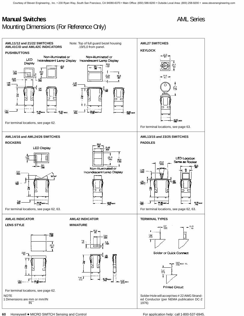
AML11/12 and 21/22 SWITCHES Note: Top of full guard bezel housing AML27 SWITCHESAML41C/D and AML42C INDICATORS .19/5,0 from panel.
PUSHBUTTONSKEYLOCK
For terminal locations, see page 62.For terminal locations, see page 63.
AML14/16 and AML24/26 SWITCHES AML13/15 and 23/25 SWITCHES
ROCKERS PADDLES
For terminal locations, see page 62, 63. For terminal locations, see page 62, 63.
AML41 INDICATOR AML42 INDICATOR TERMINAL TYPES
LENS STYLE MINIATURE
For terminal locations, see page 62.
NOTE1 Dimensions are mm or mm/IN
IN
Solder Hole will accept two #22 AWG Strand-ed Conductor (per NEMA publication DC-21976)
Courtesy of Steven Engineering , Inc. ! 230 Ryan Way, South San Francisco, CA 94080-6370 ! Main Office: (650) 588-9200 ! Outside Local Area: (800) 258-9200 ! www.stevenengineering.com

Manual Switches AML SeriesMounting Dimensions (For Reference Only)
For application help: call 1-800-537-6945. Honeywell 1 MICRO SWITCH Sensing and Control 61
AML31/32 SWITCHES AML34/36 SWITCHES
PUSHBUTTON ROCKER
AML33/35 SWITCHES TERMINAL LOCATIONS
PADDLE PUSHBUTTON ROCKER AND PADDLE
AML43 INDICATORS PANEL CUTOUT FOR SINGLE-STATIONFRONT-OF-PANEL MOUNTING
Recommended panel thickness: .060-.187/1,52-4,75
NOTES1 Dimensions are mm or mm/IN
IN
Manufacturers logo on this side of housing
Solder Hole Will Accept One #14 AWG Stranded Conductor(Per NEMA Publication DC-2 1976)
PANEL PUNCH FOR AML SERIESA panel punch is manufactured by Greenlee-Textron Tool Co.,Rockford, IL (815-926-3011).
Manuals
Courtesy of Steven Engineering , Inc. ! 230 Ryan Way, South San Francisco, CA 94080-6370 ! Main Office: (650) 588-9200 ! Outside Local Area: (800) 258-9200 ! www.stevenengineering.com
Manual Switches AML SeriesMounting Dimensions (For Reference Only)
62 Honeywell 1 MICRO SWITCH Sensing and Control For application help: call 1-800-537-6945.
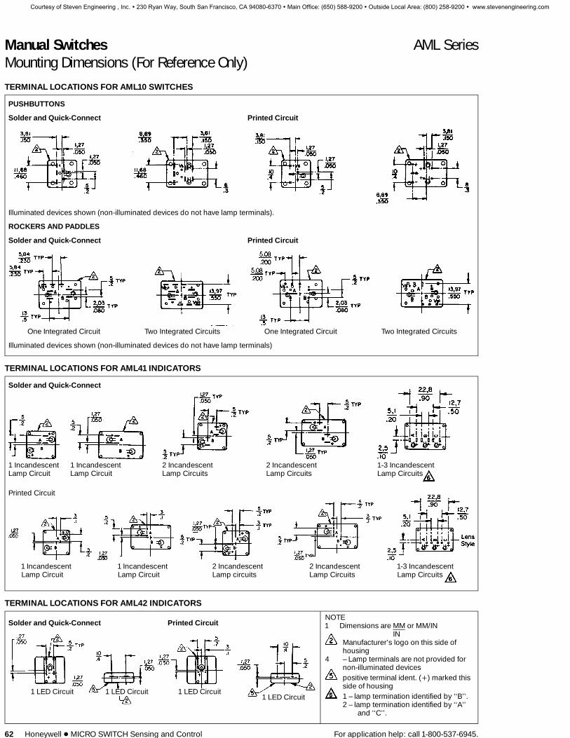
TERMINAL LOCATIONS FOR AML10 SWITCHES
PUSHBUTTONS
Solder and Quick-Connect Printed Circuit
Illuminated devices shown (non-illuminated devices do not have lamp terminals).
ROCKERS AND PADDLES
Solder and Quick-Connect Printed Circuit
One Integrated Circuit Two Integrated Circuits One Integrated Circuit Two Integrated Circuits
Illuminated devices shown (non-illuminated devices do not have lamp terminals)
TERMINAL LOCATIONS FOR AML41 INDICATORS
Solder and Quick-Connect
1 IncandescentLamp Circuit
1 IncandescentLamp Circuit
2 IncandescentLamp Circuits
2 IncandescentLamp Circuits
1-3 IncandescentLamp Circuits
Printed Circuit
1 Incandescent 1 Incandescent 2 Incandescent 2 Incandescent 1-3 IncandescentLamp Circuit Lamp Circuit Lamp circuits Lamp Circuits Lamp Circuits
TERMINAL LOCATIONS FOR AML42 INDICATORS
Solder and Quick-Connect Printed Circuit
1 LED Circuit 1 LED Circuit 1 LED Circuit1 LED Circuit
NOTE1 Dimensions are MM or MM/IN
INManufacturer’s logo on this side ofhousing
4 – Lamp terminals are not provided fornon-illuminated devicespositive terminal ident. (+) marked thisside of housing1 – lamp termination identified by ‘‘B’’.2 – lamp termination identified by ‘‘A’’
and ‘‘C’’.
Courtesy of Steven Engineering , Inc. ! 230 Ryan Way, South San Francisco, CA 94080-6370 ! Main Office: (650) 588-9200 ! Outside Local Area: (800) 258-9200 ! www.stevenengineering.com

Manual Switches AML SeriesMounting Dimensions (For Reference Only)
For application help: call 1-800-537-6945. Honeywell 1 MICRO SWITCH Sensing and Control 63
TERMINAL LOCATIONS FOR AML20 SWITCHES
PUSHBUTTON SWITCHESSolder or Quick-Connect
Terminal identification marked on each adja-cent side of housing
KEYLOCK SWITCHES
Solder or Quick-Connect
Printed Circuit
1 Pole 4 Pole2 Pole
PUSHBUTTON SWITCHESPrinted Circuit
1 Pole2 Pole
4 Pole
1 Pole 2 Pole
ILLUMINATED ROCKERS AND PADDLESSolder or Quick-Connect
Printed Circuit
1 Pole 2 Pole 1 Pole 2 Pole
NON-ILLUMINATED ROCKERS AND PADDLESSolder or Quick-Connect Printed Circuit
1 Pole 2 Pole 4 Pole
Manuals
Courtesy of Steven Engineering , Inc. ! 230 Ryan Way, South San Francisco, CA 94080-6370 ! Main Office: (650) 588-9200 ! Outside Local Area: (800) 258-9200 ! www.stevenengineering.com

Manual Switches AML SeriesMounting Dimensions (For Reference Only)
64 Honeywell 1 MICRO SWITCH Sensing and Control For application help: call 1-800-537-6945.
ANNUNCIATORS
AML45 SERIES
Manufacturer’s logo on this side of housing
For panel punch manufacturer, see page 61.
Courtesy of Steven Engineering , Inc. ! 230 Ryan Way, South San Francisco, CA 94080-6370 ! Main Office: (650) 588-9200 ! Outside Local Area: (800) 258-9200 ! www.stevenengineering.com

Manual Switches AML SeriesMounting Dimensions (For Reference Only)
For application help: call 1-800-537-6945. Honeywell 1 MICRO SWITCH Sensing and Control 65
MULTI-STATION FRONT-PANEL MOUNTING
Panel cutouts (See page 61 for panel punch manufacturer.)
Square Switches & Indicators Rect. Switches & Indicators Annunciator
(.8) (No. of units) — .045* (1.20) (No. of units) — .045* (.40) (No. of units) — .045*(20,3) (No. of units) — 1,14* (30,5) (No. of units) — 1,14* (10,1) (No. of units) — 1,14*
For each barrier, add .053/1,35 * Note: If barriers are used, do not subtract .045 in./1,14 mm from the panel cutoutformula. (.045 in./1,14mm is the allowance for the width of the bezel.)
AML61 MULTI-STATION SUBPANEL MOUNTING
Panel cutouts for AML61
Mounting BracketOrientation Width Length
A* in. .810mm 20,57 (.810)(No. of units)
B in. .810mm 20,57 (1.210)(No. of units)
C or D* in. 1.210mm 27,94 (.810)(No. of units)
*More than two cans with mounting brackets required for stripsof more than 10 units.
AML61 MOUNTING CENTERS
Mounting Centers/Number of CansMounting BracketOrientation 1 2 3 4 5 6 7 8 9 10 11 12
‘‘A’’ or ‘‘C’’ in. 1.285 2.095 2.905 3.715 4.525 5.335 6.145 6.955 7.765 8.575 9.385 10.195mm 32,64 53,21 73,79 94,36 114,94 135,51 156,08 176,66 197,23 217,81 238,38 258,95
‘‘B’’ in. 1.685 2.895 4.105 5.315 6.525 7.735 8.945 10.155mm 42,80 73,53 104,27 135,00 165,74 196,48 227,20 257,94
‘‘D’’ or ‘‘E’’ in. on CL .807 1.614 2.421 3.228 4.035 4.842 5.649 6.456 7.263 8.070 8.877mm on CL 20,50 41,00 61,49 81,99 102,49 122,99 143,48 163,98 184,48 204,98 225,48
Tolerance J ±.015
C
D
E
B
A
Manuals
Courtesy of Steven Engineering , Inc. ! 230 Ryan Way, South San Francisco, CA 94080-6370 ! Main Office: (650) 588-9200 ! Outside Local Area: (800) 258-9200 ! www.stevenengineering.com

Manual Switches AML SeriesMounting Dimensions (For Reference Only)
66 Honeywell 1 MICRO SWITCH Sensing and Control For application help: call 1-800-537-6945.
AML75 PANEL SEAL ACCESSORY
Panel cutoutsMultiple panel sealed units should not bemounted together in a single elongatedslot, since this would create an unsealedspace between each unit.
Side-by-side mounting can be achieved,per the center-to-center dimensionsshown in the drawing. (Dotted lines indi-cate the seal bases which are abutting atfront of panel.)
AML75 seals are not designed for usewith the AML61 mounting system.
NOTE: Suggested cutout dimensions arebased on an .125N/3,18 mm panel thick-ness. Individual preferences for inpanel fit
may require measurement of assembliesbefore panels are cut.
AML76 SWITCH GUARD ACCESSORY
PANEL CUTOUTS
Courtesy of Steven Engineering , Inc. ! 230 Ryan Way, South San Francisco, CA 94080-6370 ! Main Office: (650) 588-9200 ! Outside Local Area: (800) 258-9200 ! www.stevenengineering.com

Manual Switches AML11 SeriesSolid State Pushbutton
For application help: call 1-800-537-6945. Honeywell 1 MICRO SWITCH Sensing and Control 21
INCANDESCENT OR NON-LIGHTED DISPLAY
Buttons ordered separately.
FEATURES1 Hall effect reliability.1 Provides low voltage signals that
interface with nearly all DC logic levelloads.
1 5 VDC, 6-16 VDC and 4.5-24 VDCsupply voltage.
1 Full guard bezel option.1 Lamps can be furnished installed or
ordered separately.1 UL recognized.1 Lamp circuit independent of switch
circuit.
AML11 ORDER GUIDEAML11 B B A 2 AA
HousingType
Standard Bezel:AML11B Square Non-LightedAML11C Square 1 Lamp Ckt.AML11E Rect. Non-LightedAML11F Rect. 1 Lamp Ckt.AML11G Rect. 2 Lamp Ckts.
Full Guard Bezel:AML11H Square Non-LightedAML11J Square 1 Lamp Ckt.AML11K Rect. Non-LightedAML11L Rect. 1 Lamp Ckt.AML11M Rect. 2 Lamp Ckts.
BezelColor
BBlack
IncandescentLamp Type
ANo LampInstalled
B6 V Lamp*
C14 V Lamp*
E28 V Lamp*
TerminalType
2.110 × .020(Solder or
Quick-Connect)
3.025 H .025
(PrintedCircuit, orPush-On)
CircuitryCodes
5 VDCSinking
AAMomentary
Action
AEAlternate
Action
6-16 VDCSinking
BAMomentary
Action
BEAlternate
Action
5 VDCScan**
CAMomentary
Action
CEAlternate
Action
4.5-24VDC
Sinking
DAMomentary
Action
DEAlternate
Action
* Lamps will be installed per each lamp circuitspecified in the Housing Type.
** See ‘‘Scan Switches,’’ next page.
Example: AML11BBA2AASquare pushbutton switch housing, non-lighted; black bezel; .110 × .020 termination;momentary action; current sinking output for use with 5 volt supply.
CURRENT SINKING OUTPUTAML10 SERIES
A permanent magnet plunger moves ad-jacent to the Hall effect integrated circuitto give a digital, current sinking normallyhigh output.
Manuals
Courtesy of Steven Engineering , Inc. ! 230 Ryan Way, South San Francisco, CA 94080-6370 ! Main Office: (650) 588-9200 ! Outside Local Area: (800) 258-9200 ! www.stevenengineering.com

Manual Switches AML12 SeriesSolid State Pushbutton
22 Honeywell 1 MICRO SWITCH Sensing and Control For application help: call 1-800-537-6945.
LED DISPLAY
LED ‘‘window’’ buttons ordered separately.
LEDs are not replaceable.
FEATURES1 Hall effect reliabilty (Refer to facing
page for electrical specifications.)1 Rectangular, high efficiency LED’s
give flush display area and wide angleindication.
1 Available with or without diodeprotection for the LED’s.
1 5 thru 24 VDC devices have aninternal resistor to maintain LEDcurrent at nominal 20 mA.
Electrical Data Page 20Buttons Page 43, 44Lamps and LEDs Page 59Accessories Page 57, 58Mounting Dimensions Page 60, 62
1 LED circuit independent of switchcircuit.
1 UL recognized.
AML12 ORDER GUIDEAML12C B B 2 AA
Housing TypeStandard Bezel:
AML12C Square 1 LED
Full Guard Bezel:AML12J Square 1 LED
BezelColor
BBlack
LED Color/Voltage
RedB V*C 5 VD 10 VE 15 VF 24 V
YellowH V*J 5 VK 10 VL 15 VM 24 V
GreenR V*S 5 VT 10 VW 15 VX 24 V
Terminal Type/Diode Protection
2.110 × .020(Solder or
Quick-Connect)
3.025 × .025
(Printed Circuitor Push-On)
8.110 × .020With DiodeProtection
CircuitryCodes
5 VDCSinking
AAMomentary
Action
AEAlternate
Action
6-16 VDCSinking
BAMomentary
Action
BEAlternate
Action
5 VDCScan**
CAMomentary
Action
CEAlternate
Action
4.5-24VDC
Sinking
DAMomentary
Action
DEAlternate
Action* See LED application information for devices
without current-limiting resistor, page 59.
Example: AML12CBB2AASquare pushbutton switch housing;black bezel; red LED; .110 × .020 termina-tion; current sinking output for use with 5volt supply; momentary action.
AML11/12 HALL EFFECT SCAN SWITCHES
Scan switches interface directly with aport expander and microcomputer to op-erate either in a scan matrix or as an indi-vidual function switch with a level sourc-ing signal (emitter follower). Scanning isused to look at each switch in a matrix tosee which stations are active. The scanmatrix significantly lowers overall powerconsumption, since each switch requirespower only while being strobed.
In the scanned mode, the minus supplyconnection becomes the scanning inputconnection. When this input is high, theswitch is de-energized and does not con-sume power. When the scan input is low,the switch will draw current as it normallydoes when energized. If the button is de-pressed when the scan input is low, theoutput will be high. The output remainslow if the button is not depressed duringthe scan cycle.
ELECTRICAL DATACircuitry Termination
Dotted lines denote rectangular housing.1 The ‘‘MICRO SWITCH’’ identification is shown on
this side of the switch housings.
Courtesy of Steven Engineering , Inc. ! 230 Ryan Way, South San Francisco, CA 94080-6370 ! Main Office: (650) 588-9200 ! Outside Local Area: (800) 258-9200 ! www.stevenengineering.com
Manual Switches AML13 SeriesSolid State Paddle
For application help: call 1-800-537-6945. Honeywell 1 MICRO SWITCH Sensing and Control 23
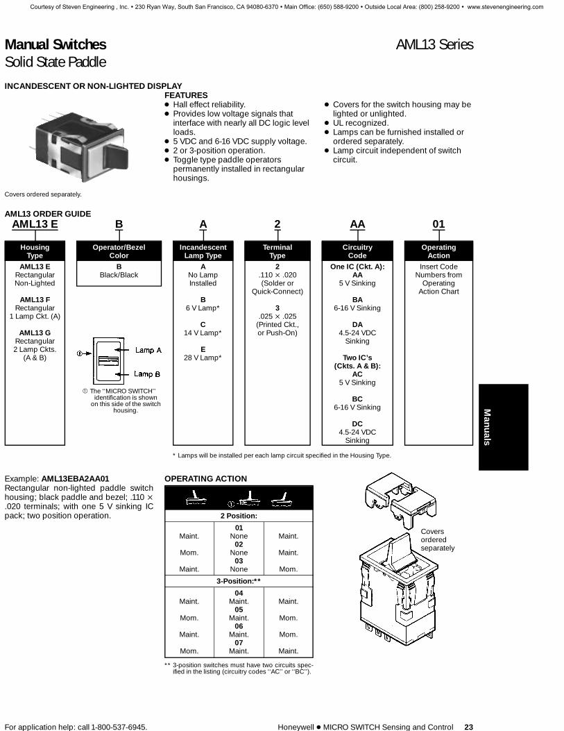
INCANDESCENT OR NON-LIGHTED DISPLAY
Covers ordered separately.
FEATURES1 Hall effect reliability.1 Provides low voltage signals that
interface with nearly all DC logic levelloads.
1 5 VDC and 6-16 VDC supply voltage.1 2 or 3-position operation.1 Toggle type paddle operators
permanently installed in rectangularhousings.
1 Covers for the switch housing may belighted or unlighted.
1 UL recognized.1 Lamps can be furnished installed or
ordered separately.1 Lamp circuit independent of switch
circuit.
AML13 ORDER GUIDEAML13 E B A 2 AA 01
Housing Operator/Bezel Incandescent Terminal Circuitry OperatingType Color Lamp Type Type Code Action
AML13 ERectangularNon-Lighted
AML13 FRectangular
1 Lamp Ckt. (A)
AML13 GRectangular2 Lamp Ckts.
(A & B)
BBlack/Black
ANo LampInstalled
B6 V Lamp*
C14 V Lamp*
E28 V Lamp*
2.110 × .020(Solder or
Quick-Connect)
3.025 × .025
(Printed Ckt.,or Push-On)
One IC (Ckt. A):AA
5 V Sinking
BA6-16 V Sinking
DA4.5-24 VDC
Sinking
Two IC’s(Ckts. A & B):
AC5 V Sinking
BC6-16 V Sinking
DC4.5-24 VDC
Sinking
Insert CodeNumbers from
OperatingAction Chart
1 The ‘‘MICRO SWITCH’’identification is shown
on this side of the switchhousing.
* Lamps will be installed per each lamp circuit specified in the Housing Type.
Example: AML13EBA2AA01Rectangular non-lighted paddle switchhousing; black paddle and bezel; .110 ×.020 terminals; with one 5 V sinking ICpack; two position operation.
OPERATING ACTION
2 Position:
01Maint. None Maint.
02Mom. None Maint.
03Maint. None Mom.
3-Position:**
04Maint. Maint. Maint.
05Mom. Maint. Mom.
06Maint. Maint. Mom.
07Mom. Maint. Maint.
** 3-position switches must have two circuits spec-ified in the listing (circuitry codes ‘‘AC’’ or ‘‘BC’’).
Coversorderedseparately
Manuals
Courtesy of Steven Engineering , Inc. ! 230 Ryan Way, South San Francisco, CA 94080-6370 ! Main Office: (650) 588-9200 ! Outside Local Area: (800) 258-9200 ! www.stevenengineering.com

Manual Switches AML15 SeriesSolid State Paddle
24 Honeywell 1 MICRO SWITCH Sensing and Control For application help: call 1-800-537-6945.
LED DISPLAY
Covers with LED ‘‘window’’ ordered separately.
LEDs are not replaceable.
FEATURES1 Hall effect reliabilty.1 Rectangular, high efficiency LED’s
give flush display area and wide angleindication.
1 Available with or without diodeprotection for the LED’s.
1 5 thru 24 VDC devices have aninternal resistor to maintain LEDcurrent at nominal 20 mA.
1 LED circuit independent of switchcircuit.
1 UL recognized.
Electrical Data Page 20Paddle Covers Page 48, 49Lamps Page 59Accessories Page 57, 58Mounting Dimensions Page 60, 62
AML15 ORDER GUIDEAML15 F B B 2 AA 01 R X
Housing Operator LED Terminal Type/ Circuitry Operating LED Color LED ColorType Bezel Color Voltage Diode Protection Code Action (LED A) (LED B)
AML15 FRect.1 LED
AML15 GRect.
2 LED’s
BBlack/Black
BV*
C5 V
D10 V
E15 V
F24 V
2.110 × .020(Solder or
Quick-Connect)
3.025 × .025
(Printed Circuit,or Push-On)
8.110 × .020
w/Diode Protectionfor LED
One IC(Ckt. A):
AA5 V Sinking
BA6-16 V Sinking
DA4.5-24 VDC
Sinking
Two IC’s(Ckts. A & B):
AC5 V Sinking
BC6-16 V Sinking
DC4.5-24 VDC
Sinking
InsertCode
Numbersfrom
OperatingActionChart
RRed
YYellow
GGreen
XNo LED
RRed
YYellow
GGreen
XNo LED
* See LED application information for devices without current-limiting resistor, page 59.
Example: AML15FBB2AA01RXRectangular paddle switch housing withone LED, without resistor, black paddleand bezel; .110 × .020 terminals, with one5 V sinking IC pack; 2-position operation.
CIRCUIT OUTPUT STATES
Ckt. LowA (operated) High High
Ckt. LowB High High (operated)
Switch basetermination
1 The ‘‘MICRO SWITCH’’ identification is on this side of the switch housing.
Courtesy of Steven Engineering , Inc. ! 230 Ryan Way, South San Francisco, CA 94080-6370 ! Main Office: (650) 588-9200 ! Outside Local Area: (800) 258-9200 ! www.stevenengineering.com

Manual Switches AML21 SeriesElectronic Control Pushbutton
For application help: call 1-800-537-6945. Honeywell 1 MICRO SWITCH Sensing and Control 27
INCANDESCENT OR NON-LIGHTED DISPLAY
Buttons ordered separately.
FEATURES1 1, 2, or 4 poles.1 Silver or gold contacts.1 Full guard bezel option.1 Momentary or 2-level alternate action
(push-on, push-off).1 UL recognized, CSA certified.1 Lamps can be furnished installed or
ordered separately.1 Lamp circuit independent of switch circuit.
AML21 Series: 1 pole and 2-poleonly.
AML21 ORDER GUIDEAML21 B B A 2 AA
Housing Bezel Incandescent Terminal Circuitry CodesType Color Lamp Type Type (Each pole has double-throw)
Standard Bezel: B A 2 Silver Mom. ActionAML21B Square Non-LightedAML21C Square 1 Lamp Ckt.AML21E Rect. Non-LightedAML21F Rect. 1 Lamp Ckt.AML21G Rect. 2 Lamp Ckts.
Full Guard Bezel:AML21H Square Non-LightedAML21J Square 1 Lamp Ckt.AML21K Rect. Non-LightedAML21L Rect. 1 Lamp Ckt.AML21M Rect. 2 Lamp Ckts.
Black No LampInstalled
B6 V Lamp*
C14 V Lamp*
E28 V Lamp*
.110 × .020(Solder or
Quick-Connect)
3.025 × .025
(Printed Ckt. orPush-On)
Contacts AA 1-PoleAC 2-PoleCC 4-Pole
Alt. ActionAB 1-PoleAD 2-PoleCD 4-Pole
GoldContacts
Mom. ActionBA 1-PoleBC 2-PoleDC 4-Pole
Alt. ActionBB 1-PoleBD 2-PoleDD 4-Pole
Gold-PlatedSilver
Contacts
Mom. ActionEA 1-PoleEC 2-Pole
Alt. ActionEB 1-PoleED 2-Pole
* Lamps will be installed per each lamp circuit specified in the Housing Type.
Example: AML21BBA2AASquare pushbutton switch housing non-lighted; black bezel; .110 × .020 termina-tion; momentary action; 1-pole, double-throw; silver contacts.
Manuals
Courtesy of Steven Engineering , Inc. ! 230 Ryan Way, South San Francisco, CA 94080-6370 ! Main Office: (650) 588-9200 ! Outside Local Area: (800) 258-9200 ! www.stevenengineering.com
Manual Switches AML22 SeriesElectronic Control Pushbutton
28 Honeywell 1 MICRO SWITCH Sensing and Control For application help: call 1-800-537-6945.
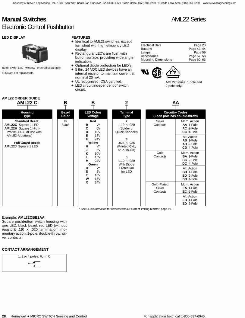
LED DISPLAY
Buttons with LED ‘‘window’’ ordered separately.
LEDs are not replaceable.
FEATURES1 Identical to AML21 switches, except
furnished with high efficiency LEDdisplay.
1 Rectangular LED’s are flush withbutton surface, providing wide angleindication.
1 Optional diode protection for LED’s.1 5 thru 24 VDC LED devices have an
internal resistor to maintain current atnominal 20 mA.
1 UL recognized, CSA certified.1 LED circuit independent of switch
circuit.
Electrical Data Page 20Buttons Page 43, 44Lamps Page 59Accessories Page 57, 58Mounting Dimensions Page 60, 63
AML22 Series: 1 pole and2-pole only.
AML22 ORDER GUIDEAML22 C B B 2 AA
Housing Bezel LED Color/ Terminal Circuitry CodesType Color Voltage Type (Each pole has double-throw)
Standard Bezel: B Red 2 Silver Mom. ActionAML22C Square 1 LEDAML22H Square 1 High-
Profile LED (For use withAML52-A buttons)
Full Guard Bezel:AML22J Square 1 LED
Black B V*C 5VD 10VE 15VF 24V
YellowH V*J 5VK 10VL 15VM 24V
GreenR V*S 5VT 10VW 15VX 24V
.110 × .020(Solder or
Quick-Connect)
3.025 × .025
(Printed Ckt.,or Push-On)
8.110 × .020With DiodeProtection
for LED
Contacts AA 1-PoleAC 2-PoleCC 4-Pole
Alt. ActionAB 1-PoleAD 2-PoleCD 4-Pole
GoldContacts
Mom. ActionBA 1-PoleBC 2-PoleDC 4-Pole
Alt. ActionBB 1-PoleBD 2-PoleDD 4-Pole
Gold-PlatedSilver
Contacts
Mom. ActionEA 1-PoleEC 2-Pole
Alt. ActionEB 1-PoleED 2-Pole
* See LED information for devices without current limiting resistor, page 59.
Example: AML22CBB2AASquare pushbutton switch housing withone LED, black bezel; red LED (withoutresistor); .110 × .020 termination; mo-mentary action, 1-pole, double-throw; sil-ver contacts.
CONTACT ARRANGEMENT
1, 2 or 4 poles: Form C
Courtesy of Steven Engineering , Inc. ! 230 Ryan Way, South San Francisco, CA 94080-6370 ! Main Office: (650) 588-9200 ! Outside Local Area: (800) 258-9200 ! www.stevenengineering.com

Manual Switches AML23 SeriesElectronic Control Paddle
For application help: call 1-800-537-6945. Honeywell 1 MICRO SWITCH Sensing and Control 29
INCANDESCENT OR NON-LIGHTED DISPLAY
Covers ordered separately.
FEATURES1 Silver or gold contacts.1 1, 2 or 4 poles.1 Toggle type paddle operators
permanently installed in rectangularhousings.
1 Covers for the switch housing may belighted or unlighted.
1 UL recognized, CSA certified.1 Lamps can be furnished installed or
ordered separately.1 Lamp circuit independent of switch
circuit.
Electrical Data Page 20Paddle Covers Page 48Lamps Page 59Accessories Page 57, 58Mounting Dimensions Page 60,63
AML23 Series: 1 pole and2-pole only.
AML23 ORDER GUIDEAML23 E B A 2 AA 01
Housing Operator/Bezel Incandescent Terminal Circuitry OperatingType Color Lamp Type Type Codes Action
AML23 E B A 2 Insert Codeletters asshown in
Circuitry Chart
Insert Code numbersfrom Operating
Action ChartRectangular Black/Black No Lamp
Installed
B6 V Lamp*
C14 V Lamp*
E28 V Lamp*
.110 × .020(Solder or
Quick-Connect)
3.025 × .025
(Printed Ckt.,or Push-on)
Non-Lighted
AML23 FRectangular
1 Lamp Ckt. (A)
AML23 GRectangular2 Lamp Ckts.
(A & B)
* Lamps will be installed per each lamp circuit specified in the Housing Type.
1 The ‘‘MICRO SWITCH’’identification is shownon this side of theswitch housings.
Example: AML23EBA2AA01Rectangular non-lighted paddle switchhousing; black paddle and bezel; .110 ×.020 terminals; with one circuit ON andone circuit OFF in each extreme operatorposition (maintained).
CIRCUITRY
Silver Gold 2-Position 3-PositionContacts Contacts
AA BA
AC BC
(Non-illuminatedswitches only)
CA DA
CC DC
(Non-illuminatedswitches only)
OPERATING ACTION
2-Position:
01Maint. None Maint.
02Mom. None Maint.
03Maint. None Mom.
3-Position:
04Maint. Maint. Maint.
05Mom. Maint. Mom.
06Maint. Maint. Mom.
07Mom. Maint. Maint.
Manuals
Courtesy of Steven Engineering , Inc. ! 230 Ryan Way, South San Francisco, CA 94080-6370 ! Main Office: (650) 588-9200 ! Outside Local Area: (800) 258-9200 ! www.stevenengineering.com

Manual Switches AML24 SeriesElectronic Control Rocker
30 Honeywell 1 Sensing and Control 1 1-800-537-6945 USA 1 F1-815-235-6847 International 1 1-800-737-3360 Canada
INCANDESCENT OR NON-LIGHTED DISPLAY
Rocker operators ordered separately.
FEATURES1 Silver or gold contacts.1 2 or 3 position operation.1 UL recognized, CSA certified.1 Lamps can be furnished installed or
ordered separately.1 Lamp circuit independent of switch
circuit.
Electrical Data page 19Rockers page 51Lamps page 58Accessories pages 56, 57Mounting Dimensions pages 59, 62
* *
*AML24 Series: 1 pole and2-pole only.
AML24 ORDER GUIDEAML24 E B A 2 AA 01
Housing Bezel Incandescent Terminal Circuitry OperatingType Color Lamp Type Type Codes Action
AML24 E B A 2 Insert Codeletters asshown in
Circuitry Chart
Insert Code numbersfrom Operating
Action ChartRectangular Black No Lamp
Installed
B6 V Lamp*
C14 V Lamp*
E28 V Lamp*
.110 × .020(Solder or
Quick-Connect)
3.025 × .025
(Printed Ckt.,or Push-on)
Non-Lighted
AML24 FRectangular
1 Lamp Ckt. (A)
AML24 GRectangular2 Lamp Ckts.
1 The ‘‘MICRO SWITCH’’identification is shownon this side of theswitch housings.
* Lamps will be installed per each lamp circuit specified in the Housing Type.
Example: AML24EBA2AA01Rectangular non-lighted rocker switchhousing; black bezel; .110 × .020 termi-nals; with one circuit ON and one circuitOFF in each extreme operator position(maintained).
CIRCUITRY
Silver Gold 2-Position 3-PositionContacts Contacts
AA BA
AC BC
(Non-illuminatedswitches only)
CA DA
CC DC
(Non-illuminatedswitches only)
OPERATING ACTION
2-Position:
01Maint. None Maint.
02Mom. None Maint.
03Maint. None Mom.
3-Position:
04Maint. Maint. Maint.
05Mom. Maint. Mom.
06Maint. Maint. Mom.
07Mom. Maint. Maint.
Courtesy of Steven Engineering, Inc.-230 Ryan Way, South San Francisco, CA 94080-6370-Main Office: (650) 588-9200-Outside Local Area: (800) 258-9200-www.stevenengineering.com

Manual Switches AML25 SeriesElectronic Control Paddle
30 Honeywell 1 MICRO SWITCH Sensing and Control For application help: call 1-800-537-6945.
LED DISPLAY
Covers with LED ‘‘window’’ ordered separately.
FEATURES1 Identical to AML23, except furnished
with one or two rectangular highefficiency LED’s which give flushdisplay area and wide angleindication.
1 Available with or without diodeprotection for LED’s.
1 LED circuit independent of switchcircuit.
1 5 thru 24 VDC devices have internalresistor to maintain current at nominal20 mA.
1 UL recognized, CSA certified.
AML25 Series: 1 pole and2-pole only.
AML25 ORDER GUIDEAML25 F B B 2 AA 01 R X
Housing Operator/ LED Terminal Type/ Circuitry Operating LED Color LED ColorType Bezel Color Voltage Diode Protection Codes Code (LED A) (LED B)
AML25 F B B 2 Insert code Insert code R RRectangular Black/Black V* .110 × .020 letters numbers Red Red
1 LED (Solder or Q-C) as shown in from Y YC Circuitry Operating Yellow Yellow
AML25 G 5 V 3 Chart Action G GRectangular .025 × .025 on p. 29 Chart Green Green
2 LED’s D (Printed Ckt.,LED version
on p. 29 X X10 V or Push-On
availableNo LED No LED
only withE 8AA15 V .110 × .020BAw/DiodeCAF protectionDA24 V
circuitry
*See LED application information for devices without current-limiting resistor, page 59.
Example: AML25FBB2AA01RXRectangular paddle switch; illuminatedwith one red LED, this device has a blackpaddle and bezel, and .110 × .020 termi-nals; with one circuit ON and one circuitOFF in each extreme operator position(maintained).
† For further information on replacementLED’s, call the 800 number.
Coversorderedseparately 1 The ‘‘MICRO SWITCH’’ identification is
shown on this side of the switch housings.
Courtesy of Steven Engineering , Inc. ! 230 Ryan Way, South San Francisco, CA 94080-6370 ! Main Office: (650) 588-9200 ! Outside Local Area: (800) 258-9200 ! www.stevenengineering.com

Manual Switches AML26 SeriesElectronic Control Rocker
Honeywell 1 Sensing and Control 1 1-800-537-6945 USA 1 F1-815-235-6847 International 1 1-800-737-3360 Canada 31
LED DISPLAY
Rocker operators ordered separately.
LEDs are not replaceable.
FEATURES1 Identical to AML24, except furnished
with one or two rectangular highefficiency LED’s which give flushdisplay area and wide angleindication.
1 Available with or without diodeprotection for LED’s.
1 LED circuit independent of switchcircuit.
Electrical Data page 19Rockers page 52Lamps and LEDs page 58Accessories page 57Mounting Dimensions pages 59, 62
1 5 thru 24 VDC LED devices haveinternal resistor to maintain current atnominal 20 mA.
1 UL recognized, CSA certified.
* *
*AML26 Series: 1 pole and2-pole only.
AML26 ORDER GUIDEAML26 F B B 2 AA 01 R X
Housing LED Terminal Type/ Circuitry Operating LED Color LED ColorType Bezel Color Voltage Diode Protection Codes Action (LED A) (LED B)
AML26 F B B 2 Insert code Insert code R R1 LED Black V* .110 × .020 letters numbers Red Red
(Solder or as shown in from Y YAML26 G C Quick-Connect Circuitry Operating Yellow Yellow2 LED’s 5 V Chart Action G G
3 Chart Green GreenD .025 × .025
LED versionX X
10 V (Printed Ckt.,available
No LED No LEDor Push-On)
only withEAA15 V 8BA.110 × .020CAF w/DiodeDA24 V for LED
circuitryprotection
*See LED application information for devices without current-limiting resistor, page 58.
Example: AML26FBB2AA01RXRectangular rocker switch; illuminatedwith one LED, this device has a blackbezel, .110 × .020 terminals; with onecircuit ON and one circuit OFF in eachextreme operator position (maintained).
1 The ‘‘MICRO SWITCH’’ identification isshown on this side of the switch housings.
Rockerorderedseparately
Manuals
Courtesy of Steven Engineering, Inc.-230 Ryan Way, South San Francisco, CA 94080-6370-Main Office: (650) 588-9200-Outside Local Area: (800) 258-9200-www.stevenengineering.com

Manual Switches AML27 SeriesElectronic Control Keylock
For application help: call 1-800-537-6945. Honeywell 1 MICRO SWITCH Sensing and Control 33
NON-LIGHTED FEATURES1 Enable control of access to computer
peripherals, keyboards, point-of-saleterminals, and security systems whichare locked when unattended; andother locations where tampering mustbe discouraged.
1 2 or 3 positions, maintained (90°throw) and momentary action (60°throw).
1 5-bit key combinations
Electrical Data Page 19Mounting Dimensions Page 60, 63Accessories Pages 57-58
1 UL recognized, CSA certified.1 Static discharge protection (up to 20
kV when grounded).
AML27 ORDER GUIDEAML27 A B K 2 AA 21 BA
Circuitry Codes Operation ActionHousing Bezel Button Terminal (Each pole has (Key out in center position, Key
Type Color Color Type double-throw) except where noted) Combinations
AML27 A B K 2 Silver Contacts: (Two KeysBlack Black .110 × .020 AA Furnished)
Square (Solder or 1 polehousing Quick-Connect) AC BA BL
2 pole BB BMNon-Lighted 3 BC BN
.025 × .025 Gold Contacts: BD BP(Printed BA BE BQ
BF BRBG BSBH BTBJ BVBK BW
Circuit or 1 polePush-On) BC
2 pole
CCW Center CW
21None Maint. Maint.
22*None Maint. Maint.
23None Maint. Mom.
24Maint. Maint. Maint.
25Mom. Maint. Mom.
26**Maint. Maint. Maint.
27***Mom. Maint. Maint.
28***Maint. Maint. Maint.
29†Maint. Maint. Maint.
30†Maint. Maint. Mom.
31††Maint. Maint. Mom.
* Key out in both positions.** Key out in all three positions.
*** Key out in center and CW posi-tions.
† Key out in center andCCW positions.
†† Key out in CCW only.
REPLACEMENT KEYSOne key per listing.
KeyCom-
binationKey
CodeCatalogListing
BA 110 30PA101-AMLBB 109 30PA102-AMLBC 108 30PA103-AMLBD 107 30PA104-AMLBE 106 30PA105-AMLBF 105 30PA106-AMLBG 104 30PA107-AMLBH 103 30PA108-AMLBJ 102 30PA109-AMLBK 101 30PA110-AMLBL 111 30PA111-AMLBM 112 30PA112-AMLBN 113 30PA113-AMLBP 114 30PA114-AMLBQ 115 30PA115-AMLBR 116 30PA116-AMLBS 117 30PA117-AMLBT 118 30PA118-AMLBV 119 30PA119-AMLBW 120 30PA120-AML
Note: These keys fit the 5-bit keylocks inthe Order Guide. To order replacementkeys for our old style 4-bit key combina-tions, see below.
ORDER GUIDE FOR OLD STYLE AML27 REPLACEMENT KEYSOne key per listing.
KeyComb.
KeyCode
CatalogListing
AA 601 30PA3-AMLAB 602 30PA8-AMLAC 604 30PA9-AMLAD 607 30PA10-AMLAE 608 30PA11-AML
Specify different Key Combinations toacquire different keys, i.e.;
AML27ABK2AA21BB andAML27ABK2AA21BK have different keys.AML27ABK2AA21BB andAML27ABK3BC25BB have identical inter-changeable keys.Example: AML27ABK2AC28BBSquare housing; black bezel and button; .110× .020 terminals; 2-pole double-throw; silvercontacts; 3-position maintained and keycode ‘‘BB’’.
CIRCUITRY2-Position Switches:
Key TurnedNormal to Right
Position* (CW)
1 Pole
2 Pole
KeyComb.
KeyCode
CatalogListing
AF 610 30PA12-AMLAG 612 30PA13-AMLAH 614 30PA14-AMLAJ 615 30PA15-AMLAK 616 30PA16-AML
3-Position Switches (Available in 2-pole only.)
KeyTurnedto Left(CCW)
NormalPosition*
KeyTurned to
Right (CW)
2 Pole
* Circuit remains the same with key in or out.
28 and 29 op-erating actionsshould be usedwith Key Com-binations BA,BB, BG or BK.
Manuals
Courtesy of Steven Engineering , Inc. ! 230 Ryan Way, South San Francisco, CA 94080-6370 ! Main Office: (650) 588-9200 ! Outside Local Area: (800) 258-9200 ! www.stevenengineering.com

Manual Switches AML31/32 SeriesPower Duty Pushbutton
34 Honeywell 1 MICRO SWITCH Sensing and Control For application help: call 1-800-537-6945.
INCANDESCENT, NEON, OR NON-LIGHTED DISPLAY
Buttons ordered separately.
FEATURES1 UL recognized, CSA certified.1 AML31 lamp circuit independent of
switch circuit.
AML31 Series: 2-pole.AML32 Series: 2-pole.
CONTACT ARRANGEMENT
2 poles (Form X)
AML31 ORDER GUIDEAML31 accepts one incandescent lamp which can be furnished installed or ordered separately.
AML31 E B A 4 AC
Housing Bezel Incandescent Terminal CircuitryType Color Lamp Type Type Codes
Standard Bezel: B A 4 2-Pole, Single-ThrowAML31E Rect. Non-Lighted Black No Lamp Installed .187 × .020 Normally-Open, Form X:AML31F Rect. 1 Lamp Ckt. (Solder or
Quick-ConnectAD AC
B6 V Lamp*
C14 V Lamp*
E28 V Lamp*
Alt.Action
Mom.ActionFull Guard Bezel:
AML31K Rect. Non-LightedAML31L Rect. 1 Lamp Ckt.
* Lamps will be installed per each lamp circuit specified in the Housing Type.
Example: AML31EBA4ACRectangular pushbutton switch housing,non-lighted; black bezel; .187 × .020 ter-
minals; momentary action; 2-pole, single-throw, normally open, Form X.
AML32 ORDER GUIDEAML32 has neon lamp wired to 125 or 250 VAC resistor.
AML32 F B C 7 AC
Housing Bezel Neon Lamp Terminal Type CircuitryType Color Voltage/Color Lamp Circuit Codes
Standard Bezel: B Red 4 2-Pole, Single-ThrowNormally-Open, Form X:AML32F Rect. 1 Neon Lamp Black B 125 VAC .187 × .020
C 250 VAC (Solder orQuick-Connect)
with isolatedlamp circuit
7.187 × .020with integrallamp circuit
ADAlt.
Action
ACMom.Action
Full Guard Bezel:AML32L Rect. 1 Neon Lamp Clear
K 125 VACL 250 VAC
GreenM 125 VACP 250 VAC
Example: AML32FBC7ACRectangular pushbutton switch housing;black bezel; 250 volt, red neon lamp; .187× .020 terminals with integral lamp cir-cuit; momentary action; 2-pole, single-throw, normally open, Form X.
Isolated neon circuit Integral neon circuit
Courtesy of Steven Engineering , Inc. ! 230 Ryan Way, South San Francisco, CA 94080-6370 ! Main Office: (650) 588-9200 ! Outside Local Area: (800) 258-9200 ! www.stevenengineering.com
SEI
SEI
AML51F BUTTONS

Manual Switches AML33/35 SeriesPower Duty Paddle
For application help: call 1-800-537-6945. Honeywell 1 MICRO SWITCH Sensing and Control 35
INCANDESCENT, NEON, OR NON-LIGHTED DISPLAY
Colored housing covers ordered separately.
CONTACT ARRANGEMENT
1 or 2 poles: Form A
Electrical Data Page 20Paddle Covers Page 48Lamps Page 59Mounting Dimensions Page 61
FEATURES1 Toggle type paddle operators
permanently installed in rectangularhousings.
1 2-position maintained action.1 AML33 lamp circuit independent of
switch circuit.1 UL recognized, CSA certified.
AML33 Series: 2-pole only.AML35 Series: 1-pole and
2-pole.AML33 ORDER GUIDEAML33 accepts one incandescent lamp which can be furnished installed or ordered separately.
AML33 E B A 4 AA 01
Housing Operator/Bezel Incandescent Terminal Circuitry OperatingType Color Lamp Type Type Codes Action
AML33 E B A 4 Silver Contacts:AA
1-Pole(One Form ASingle-throw,
Normally-Open)
Rectangular Black/Black No Lamp .187 × .020(Solder or
Quick-Connect)Non-Lighted
AML33 FRectangular1 Lamp Ckt.
Installed
B6 V Lamp*
C14 V Lamp*
E28 V Lamp*
AC2-Pole
(Two Form A)
01Maint. Maint.
ON OFF
*Lamps will be installed per each lamp circuit specified in the Housing Type.
AML35 ORDER GUIDEAML35 has neon lamp wired to 125 or 250 VAC resistor.
AML35 F B B 4 AA 01
Housing Operator/Bezel Neon Lamp Terminal Type/ Circuitry OperatingType Color Voltage Lamp Circuit † Codes Action
AML35 FRectangular
1 Neon Lamp
BBlack/Black
RedB
125 VAC
C250 VAC
GreenM
125 VAC
P250 VAC
4.187 × .020(Solder or
Quick-Connect)With IsolatedLamp Circuit
7.187 × .020
With Integral LampCircuit (Available
with 2-Poledevices only
Silver Contacts:AA
(One Form ASingle-Throw)Available onlywith isolatedlamp circuit,term. type 4.
AC2-Pole
(Two Form A)
01Maint. Maint.
ON OFF
1 The ‘‘MICRO SWITCH’’ identification isshown on this side of the switch housing.
† Refer to next page for neon lamp circuitschematics.
Example: AML35FBB4AA01Rectangular paddle switch housing;black paddle and bezel; 125 VAC neonlamp; .187 × .020 terminals with isolated
lamp circuit; 1-Pole Form A Single-Throw;with circuit ON in one extreme positionand OFF in the other (maintained).
Manuals
Courtesy of Steven Engineering , Inc. ! 230 Ryan Way, South San Francisco, CA 94080-6370 ! Main Office: (650) 588-9200 ! Outside Local Area: (800) 258-9200 ! www.stevenengineering.com
Manual Switches AML34/36 SeriesPower Duty Rocker
36 Honeywell 1 MICRO SWITCH Sensing and Control For application help: call 1-800-537-6945.
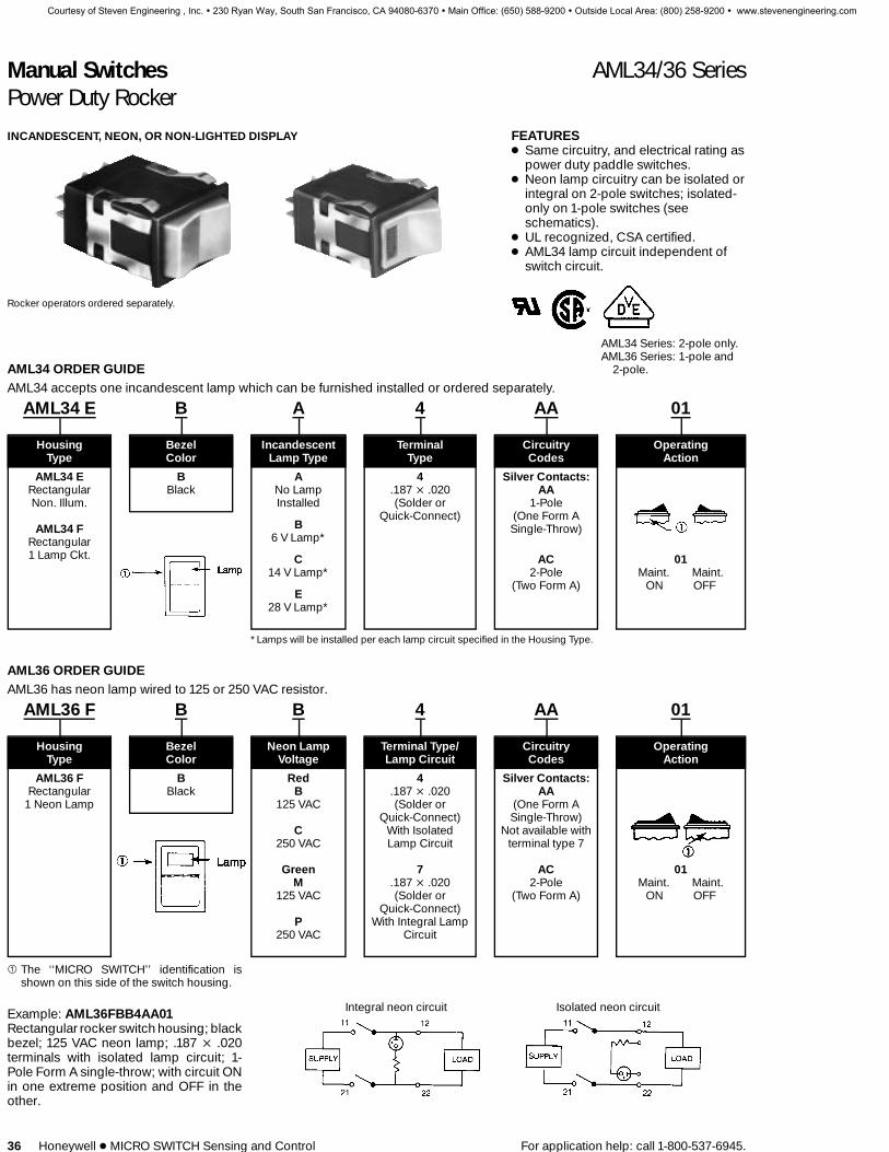
INCANDESCENT, NEON, OR NON-LIGHTED DISPLAY
Rocker operators ordered separately.
FEATURES1 Same circuitry, and electrical rating as
power duty paddle switches.1 Neon lamp circuitry can be isolated or
integral on 2-pole switches; isolated-only on 1-pole switches (seeschematics).
1 UL recognized, CSA certified.1 AML34 lamp circuit independent of
switch circuit.
AML34 Series: 2-pole only.AML36 Series: 1-pole and
2-pole.AML34 ORDER GUIDEAML34 accepts one incandescent lamp which can be furnished installed or ordered separately.
AML34 E B A 4 AA 01
Housing Bezel Incandescent Terminal Circuitry OperatingType Color Lamp Type Type Codes Action
AML34 E B A 4 Silver Contacts:AA
1-Pole(One Form ASingle-Throw)
Rectangular Black No Lamp .187 × .020(Solder or
Quick-Connect)Non. Illum.
AML34 FRectangular1 Lamp Ckt.
Installed
B6 V Lamp*
C14 V Lamp*
E28 V Lamp*
AC2-Pole
(Two Form A)
01Maint. Maint.
ON OFF
*Lamps will be installed per each lamp circuit specified in the Housing Type.
AML36 ORDER GUIDEAML36 has neon lamp wired to 125 or 250 VAC resistor.
AML36 F B B 4 AA 01
Housing Bezel Neon Lamp Terminal Type/ Circuitry OperatingType Color Voltage Lamp Circuit Codes Action
AML36 FRectangular
1 Neon Lamp
BBlack
RedB
125 VAC
C250 VAC
GreenM
125 VAC
P250 VAC
4.187 × .020(Solder or
Quick-Connect)With IsolatedLamp Circuit
7.187 × .020(Solder or
Quick-Connect)With Integral Lamp
Circuit
Silver Contacts:AA
(One Form ASingle-Throw)
Not available withterminal type 7
AC2-Pole
(Two Form A)
01Maint. Maint.
ON OFF
1 The ‘‘MICRO SWITCH’’ identification isshown on this side of the switch housing.
Example: AML36FBB4AA01Rectangular rocker switch housing; blackbezel; 125 VAC neon lamp; .187 × .020terminals with isolated lamp circuit; 1-Pole Form A single-throw; with circuit ONin one extreme position and OFF in theother.
Integral neon circuit Isolated neon circuit
Courtesy of Steven Engineering , Inc. ! 230 Ryan Way, South San Francisco, CA 94080-6370 ! Main Office: (650) 588-9200 ! Outside Local Area: (800) 258-9200 ! www.stevenengineering.com

Manual Switches AML41/42/43 SeriesLighted Indicators
For application help: call 1-800-537-6945. Honeywell 1 MICRO SWITCH Sensing and Control 37
To order lamps see page 59.
FEATURES1 Pushbutton style indicators match
display of lighted switches. Choice ofincandescent, LED, or neonillumination.
1 Lens style indicators use a specialcap-like button which covers thebezel to present a larger display area,without affecting family appearance.Up to 3-lamp split screen capability.Incandescent illumination.
AML41 AML41(Use AML51 push- (Use AML51-J/-K/-L
buttons only. lens buttons only.Page 43.) Page 43.)
AML41 INCANDESCENT DISPLAY INDICATORS ORDER GUIDEAML41 C B A 2
Housing Type Incand.Pushbutton Lens Bezel Lamp Terminal
Style: Style: Color Type Type
AML41 C AML41 J B A 2Square
1 lamp ckt.
AML41 DSquare
2 lamp ckts.
AML41 FRectangular1 lamp ckt.
AML41 GRectangular2 lamp ckts.
Rectangular1 lamp ckt.
AML41 KRectangular2 lamp ckts.
AML41 LRectangular3 lamp ckts.
Black No lampinstalled
B6 V Lamp*
C14 V Lamp*
E28 V Lamp*
.110 × .020(Solder or Quick-
Connect)
3.025 × .025
(PrintedCircuit
or Push-On)
* Lamps will be installed per each lamp circuit specified in the Housing Type.
Examples:AML41CBA2Square (pushbutton style) indicatorhousing with one lamp circuit; black be-zel; .110 × .020 termination.
AML41JBA2Rectangular (lens style) indicator hous-ing with one lamp circuit; black bezel; .110× .020 termination.
AML42C AML42S(Use AML52-C/-Apushbuttons only.
Page 44.)
AML43 neon display indicators are iden-tical to AML32 power switches, exceptbutton is furnished assembled (locked indepressed position) and there is no provi-sion for switching. Button is nonremov-able. Other button colors are available.Example:AML43FBB40RRectangular device with black bezel; 125volt red neon lamp .187 × .020 termina-tion.NOTE: Add L to neon indicator cataloglisting if legend is desired and submit Leg-end Sheet FO-63504.
AML42 LED DISPLAY INDICATORS ORDER GUIDELEDs are not replaceable.AML42 S B C 2
Housing Bezel LED Color/ Terminal Type/Type Color Voltage Diode Protection
AML42 C B Red 2 8Square Black B V* .110 × .020 .110 × .0201 LED C 5 V (Solder or Q.C.) w/diode to
D 10 V protect LEDAML42 S E 15 V 3Compact F 24 V .025 × .025 9
1 LED Yellow Green (Printed Circuit .025 × .025H V* R V* or Push-On) w/diode toJ 5 V S 5 V protect LEDK 10 V T 10 VL 15 V W 15 VM 24 V X 24 V
* See LED application data, page 59, for thesedevices without current-limiting resistor.Example: AML42SBC2
Compact indicator with black bezel; 5 voltred LED; .110 × .020 termination.
AML43 NEON DISPLAY INDICATORS ORDER GUIDEAML43 F B B 4 OR
Housing Bezel Neon Lamp Terminal ButtonType** Color Color/Voltage Type Color
AML43FRect.
BBlack
RedB 125 VC 250 V
ClearK 125 VL 250 V
GreenM 125 VP 250 V
4.187 × .020
(solderor Q.C.)
OR RedOY YellowOG GreenOW WhiteOK Black
Manuals
Courtesy of Steven Engineering , Inc. ! 230 Ryan Way, South San Francisco, CA 94080-6370 ! Main Office: (650) 588-9200 ! Outside Local Area: (800) 258-9200 ! www.stevenengineering.com

Maual Switches AML45/59 SeriesSolid State LED Annunciators
For application help: call 1-800-537-6945. Honeywell 1 MICRO SWITCH Sensing and Control 41
AML59 CAP ASSEMBLIESThe cap assembly consists of: black cap,color filter(s), and optional film legend;furnished unassembled. It snaps ontohousing, flush with the housing bezel.
Filters, assembled with their matte finishfacing the LED’s, efficiently diffuse the illu-mination. They are color-tinted to comple-ment the red, yellow, and green LED’s.
NOTE: Cap assembly should not be sub-jected to the temperature and chemicalatmosphere associated with wave solder-ing. These parts should be installed aftersoldering and cleanup.
Catalog listings for AML59 cap assem-blies are derived from the ordering guidebelow. The ordering guide for AML45 LEDhousings is on page 39.
CUSTOM LEGENDSA 2:1 drawing in black ink is required forsatisfactory reproduction of custom filmlegends. As an alternative, you may sub-mit an office copy of a page from a typo-graphic supplier catalog such as Char-tpak, Letraset, and Zipatone. MICROSWITCH can also furnish graphic leg-ends from the ‘‘Henry Dreyfus SymbolSource Book.’’ (Custom legends requirea one-time start-up charge.)
1 Viewing area inside cap:X J 1.04 min.; Y J .272 min.
2 Customers ordering film legends fromcommercial photographic or typeset-ting sources should specify that thefilm be precision cut, per the followingdimensions, to insure proper retentionand alignment on the face of the an-nunciator: A J .007 max.; B J 1.1 ±.010; C J .300 ± .003.
STANDARD LEGENDSAML59 Legend Sheet (see page 42) pro-vides ordering information for negativeand positive standard film legends in thetype style (14-point Helvetica condensedbold) shown below. Use separate legendsheet for each AML59 catalog listing andattach it (them) to your purchase order.
AML59 ORDER GUIDEAML59-R K 10 R
Filter ColorCap Cap LegendStyle Color Type Full Screen Split Screen
AML59-RFull Screen
AML59-SSplit Screen
KBlack
10No
Legend
20Negative
FilmLegend
21Positive
FilmLegend
RRed
YYellow
GGreen
RRed
YYellow
GGreen
RRed
YYellow
GGreen
Examples:AML59-RK10RFull screen style, black cap, no legend,and red filter.
AML59-SK20RYSplit screen style, black cap, negative filmlegend, red and yellow color filters.
Manuals
Courtesy of Steven Engineering , Inc. ! 230 Ryan Way, South San Francisco, CA 94080-6370 ! Main Office: (650) 588-9200 ! Outside Local Area: (800) 258-9200 ! www.stevenengineering.com

Manual Switches AML59 SeriesLegend Sheet
42 Honeywell 1 MICRO SWITCH Sensing and Control For application help: call 1-800-537-6945.
Courtesy of Steven Engineering , Inc. ! 230 Ryan Way, South San Francisco, CA 94080-6370 ! Main Office: (650) 588-9200 ! Outside Local Area: (800) 258-9200 ! www.stevenengineering.com

Manual Switches AML51 SeriesButtons/Lens for Switches and Indicators
For application help: call 1-800-537-6945. Honeywell 1 MICRO SWITCH Sensing and Control 43
AML51 PUSHBUTTON ORDER GUIDEFor Incandescent or non-lighted display switches and pushbutton style indicators.
AML51-C 10 R —
For AML11, 21, 31 switches and AML41 indicators: Display Full Color or 2ndPushbutton Style Legend/Type 1st Color Split Color Split
AML51-C AML51-F AML51-G
AML51-A AML51-H AML51-Nu
AML51-B* AML51-E* AML51-M*
AML51-R*
For AML41D indicators only:
AML51-D
RRed
YYellow
GGreen
BBlueW
WhiteK***
BlackL***
GrayA**
Amber
RRed
YYellow
GGreen
BBlueW
WhiteK***
BlackL***
GrayA**
Amber
Transmitted Color10 No legend20 With legend
on cap.
Transmitted Color(Clear cap and
color insert)11 No legend21 With legend
on insert
Dead Front(Smoky gray capand color insert)30 No legend40 With legend
on insert
Projected Color(White cap and
color insert)50 No legend60 With legend
on cap
*Available with transmitted color (10 or 20) only.
Example: AML51-C10RSquare full color button; with transmitted color,no legend: red.**Available with transmitted color and dead front only.***Black and gray not recommended for lighted display.uAML51-N buttons not available with Display/Legend Types10 and 20.Note: Dimensions include the .060 in bezel.
AML51 LENS ORDER GUIDEFor incandescent display AML41J, K, and L lens style indicators only.
AML51-J 10 R
Full ColorDisplay/Legend or 1st 2nd 3rd
Lens style Type Color Split Color Split Color Split
AML51-J
AML51-K
AML51-L
Transmitted Color R R R10 No legend Red Red Red20 With legend
Y Y YTransmitted Color Yellow Yellow Yellow
(Clear cap andcolor insert) G G G
11 No legend Green Green Green21 With legend
B B BDead Front Blue Blue Blue
(Smoky gray capand color insert) W W W30 No legend White White White40 With legend
A** A** A**Projected Color Amber Amber Amber(White cap and
color insert)50 No legend60 With legend
**Not available with projected color.
AML51 lens buttons provide added dis-play area by snapping onto and coveringthe bezel of AML41J, K, and L indicators.They do not fit other indicators or switch-es.
Example: AML51-J10RRectangular lens type button; full color;transmitted color, no lenged; red.
HOW TO ORDER BUTTON LEGENDSWhen specifying legended buttons, sub-mit a legend order sheet to cover eachlisting. To insure proper legend orienta-tion, AML housings (when viewed fromthe panel front) should have the ‘‘MICROSWITCH’’ identification facing UP onsquare devices and UP or to the LEFT onrectangular.
Button legend order sheets are shown onthe following pages. Reproduce them onyour office copier.Legend Sheet Form No.AML51 Pushbuttons FO-63394AML51 Lens buttons FO-63395AML52 Pushbuttons FO-63504AML53 Paddle switch covers FO-63567AML55 Paddle switch covers FO-63565AML54 Rockers FO-63566AML56 Rockers FO-63564
Manuals
Courtesy of Steven Engineering , Inc. ! 230 Ryan Way, South San Francisco, CA 94080-6370 ! Main Office: (650) 588-9200 ! Outside Local Area: (800) 258-9200 ! www.stevenengineering.com

Manual Switches AML51/52 SeriesButtons for Switches and Indicators
44 Honeywell 1 MICRO SWITCH Sensing and Control For application help: call 1-800-537-6945.
AML52 BUTTON ORDER GUIDEFor AML12, AML22 (w/o light pipe), AML32, AML42 LED display.
AML52-N 10 R
Button Display/Legend ButtonType Type Color
For LED DevicesAML52-C
AML52-A*
For AML32 Neon DevicesAML52-N
Transmitted Color
10No Legend
20With Legend
RRed
YYellow
GGreen
BBlue
WWhite
KBlack
AAmber
LGray
Examples:AML52-N10RRectangular full screen; for use on neonpower switch with transmitted color, nolegend; red button.
AML52-C10KSquare full screen; for use with LED de-vice; transmitted color, no legend; blackbutton.
Courtesy of Steven Engineering , Inc. ! 230 Ryan Way, South San Francisco, CA 94080-6370 ! Main Office: (650) 588-9200 ! Outside Local Area: (800) 258-9200 ! www.stevenengineering.com

Manual Switches AML52 SeriesPushbutton Legend Sheet
For application help: call 1-800-537-6945. Honeywell 1 MICRO SWITCH Sensing and Control 45
Manuals
Courtesy of Steven Engineering , Inc. ! 230 Ryan Way, South San Francisco, CA 94080-6370 ! Main Office: (650) 588-9200 ! Outside Local Area: (800) 258-9200 ! www.stevenengineering.com

Manual Switches AML51 SeriesPushbutton Legend Sheet
46 Honeywell 1 MICRO SWITCH Sensing and Control For application help: call 1-800-537-6945.
Courtesy of Steven Engineering , Inc. ! 230 Ryan Way, South San Francisco, CA 94080-6370 ! Main Office: (650) 588-9200 ! Outside Local Area: (800) 258-9200 ! www.stevenengineering.com

Manual Switches AML51 SeriesLens Legend Sheet
For application help: call 1-800-537-6945. Honeywell 1 MICRO SWITCH Sensing and Control 47
Manuals
Courtesy of Steven Engineering , Inc. ! 230 Ryan Way, South San Francisco, CA 94080-6370 ! Main Office: (650) 588-9200 ! Outside Local Area: (800) 258-9200 ! www.stevenengineering.com

Manual Switches AML53/55 SeriesCovers for Paddle Switches
48 Honeywell 1 MICRO SWITCH Sensing and Control For application help: call 1-800-537-6945.
Colored covers simply snap into the topof paddle switch housings.
COLOR DISPLAY OPTIONSTransmitted color — Color is displayedwhether lamp is On or Off. Choice of1-piece covers (types 10 or 20) or coverswith clear cap and colored translucent in-sert (types 11 or 12).
Dead front hidden color/hidden legend —Cover appears black with lamp Off. Leg-end and color appear when illuminated(types 30 or 40).
Projected color — Translucent white cov-er with transparent colored insert (types50 or 60). White cover appears coloredwhen illuminated.
AML53 PADDLE SWITCH COVER ORDER GUIDEFor AML13, AML23, and AML33 incandescent or non-lighted display.
AML53-T 10 R G
Cover Color
Paddle 1⁄2 cover, Other side ofSwitch Display/Legend or one side of two-piece cover
Cover Type Type two-piece cover (see note)
AML53-E1⁄2 Cover
AML53-TTwo-Piece Cover
Transmitted Color RRed
YYellow
GGreen
BBlueW
WhiteK*
BlackL*
GrayA**
Amber
RRed
YYellow
GGreen
BBlueW
WhiteK*
BlackL*
GrayA**
Amber
10 No legend20 With legend on
capTransmitted Color
(Clear cap andcolor insert)
11 No legend21 With legend on
insertDead Front
(Smoky gray capand color insert)30 No legend40 With legend on
insertProjected Color(White cap and
color insert)50 No legend60 With legend on
cap
Note: Only one color code letter is neces-sary when ordering 1⁄2 covers.
Example: AML53-T10RGTwo-piece cover; with transmitted color,no legend; red and green.
*Not for lighted display.**Not available with projected color.
AML55 PADDLE SWITCH COVER ORDER GUIDEFor AML35 neon display.
AML55-N 10 R Y
Paddle Switch Display/Legend Lens CoverCover Type Type Color Color
AML55-NFull Neon Cover,with colored lens
Transmitted Color10
No Legend
20With Legend
TClear
RRed
RRed
YYellow
GGreen
BBlueW
WhiteK
BlackL
GrayA
Amber
AML55-N covers have a colored lenticularlens window which extends over the neonlamp.
Example: AML55-N10RYFull neon paddle switch cover; with trans-mitted color, no legend; red lens and yel-low cover.
Courtesy of Steven Engineering , Inc. ! 230 Ryan Way, South San Francisco, CA 94080-6370 ! Main Office: (650) 588-9200 ! Outside Local Area: (800) 258-9200 ! www.stevenengineering.com
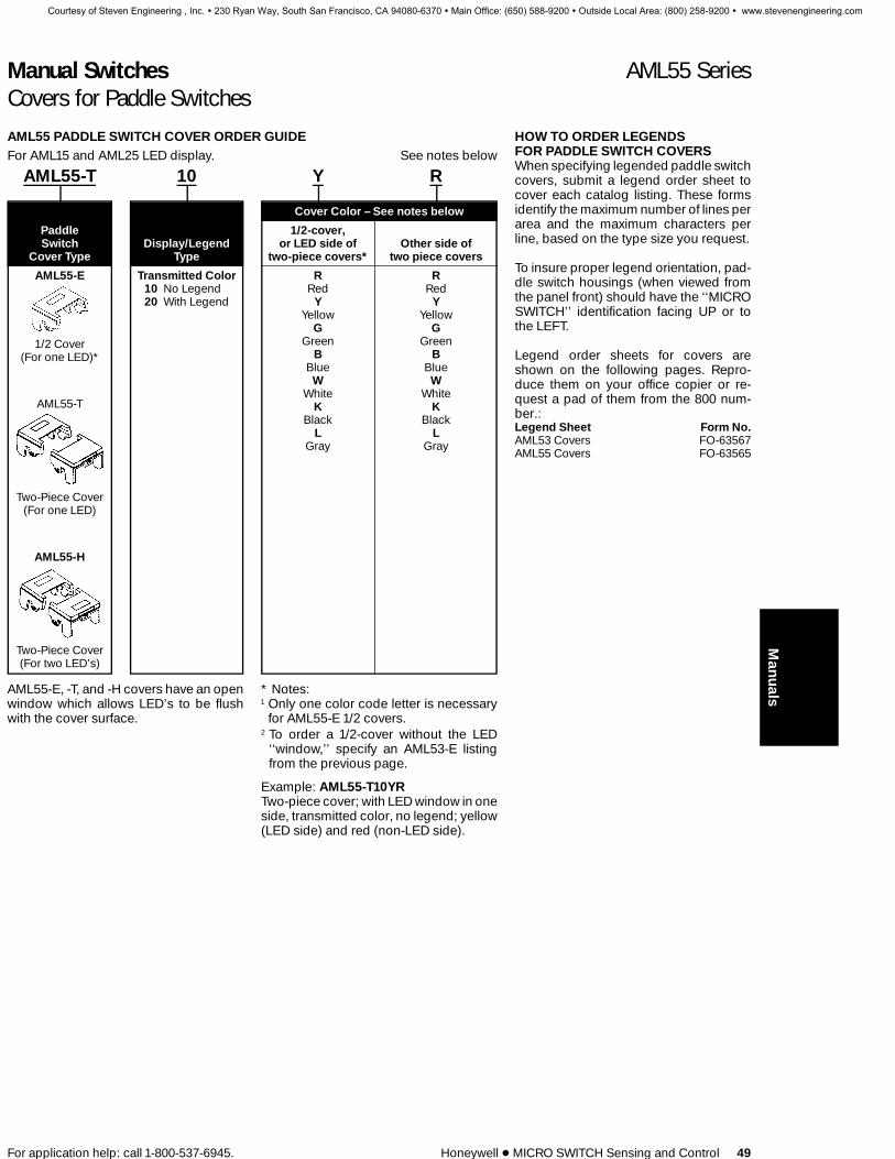
Manual Switches AML55 SeriesCovers for Paddle Switches
For application help: call 1-800-537-6945. Honeywell 1 MICRO SWITCH Sensing and Control 49
HOW TO ORDER LEGENDSFOR PADDLE SWITCH COVERSWhen specifying legended paddle switchcovers, submit a legend order sheet tocover each catalog listing. These formsidentify the maximum number of lines perarea and the maximum characters perline, based on the type size you request.
To insure proper legend orientation, pad-dle switch housings (when viewed fromthe panel front) should have the ‘‘MICROSWITCH’’ identification facing UP or tothe LEFT.
Legend order sheets for covers areshown on the following pages. Repro-duce them on your office copier or re-quest a pad of them from the 800 num-ber.:Legend Sheet Form No.AML53 Covers FO-63567AML55 Covers FO-63565
AML55 PADDLE SWITCH COVER ORDER GUIDEFor AML15 and AML25 LED display. See notes below
AML55-T 10 Y R
Cover Color – See notes below
Paddle 1/2-cover,Switch Display/Legend or LED side of Other side of
Cover Type Type two-piece covers* two piece covers
AML55-E
1/2 Cover(For one LED)*
AML55-T
Two-Piece Cover(For one LED)
AML55-H
Two-Piece Cover(For two LED’s)
Transmitted Color10 No Legend20 With Legend
R RRed Red
YYellow
GGreen
BBlueW
WhiteK
BlackL
Gray
YYellow
GGreen
BBlueW
WhiteK
BlackL
Gray
AML55-E, -T, and -H covers have an openwindow which allows LED’s to be flushwith the cover surface.
* Notes:1 Only one color code letter is necessary
for AML55-E 1/2 covers.2 To order a 1/2-cover without the LED
‘‘window,’’ specify an AML53-E listingfrom the previous page.
Example: AML55-T10YRTwo-piece cover; with LED window in oneside, transmitted color, no legend; yellow(LED side) and red (non-LED side).
Manuals
Courtesy of Steven Engineering , Inc. ! 230 Ryan Way, South San Francisco, CA 94080-6370 ! Main Office: (650) 588-9200 ! Outside Local Area: (800) 258-9200 ! www.stevenengineering.com
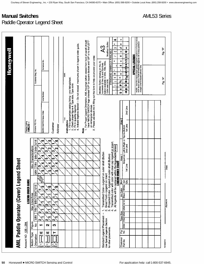
Manual Switches AML53 SeriesPaddle Operator Legend Sheet
50 Honeywell 1 MICRO SWITCH Sensing and Control For application help: call 1-800-537-6945.
Courtesy of Steven Engineering , Inc. ! 230 Ryan Way, South San Francisco, CA 94080-6370 ! Main Office: (650) 588-9200 ! Outside Local Area: (800) 258-9200 ! www.stevenengineering.com

Manual Switches AML55 SeriesPaddle Legend Sheet
For application help: call 1-800-537-6945. Honeywell 1 MICRO SWITCH Sensing and Control 51
Manuals
Courtesy of Steven Engineering , Inc. ! 230 Ryan Way, South San Francisco, CA 94080-6370 ! Main Office: (650) 588-9200 ! Outside Local Area: (800) 258-9200 ! www.stevenengineering.com

Manual Switches AML54/56 SeriesRocker Switch Operators
52 Honeywell 1 MICRO SWITCH Sensing and Control For application help: call 1-800-537-6945.
COLOR DISPLAY OPTIONS
Rocker operators are assembled to theswitches by simply snapping them intorecesses in the switch operator sockets.
Transmitted color — Color is displayedwhether lamp is On or Off. Choice of 1-piece rockers (types 10 or 20) or rockerswith clear cap and colored translucent in-sert (types 11 or 12).
Dead front hidden color/hidden legend —Rocker appears black with lamp Off. Leg-end and color appear when illuminated(types 30 or 40).
Projected color — Translucent whiterocker with transparent colored insert(types 50 or 60). White rocker appearscolored when illuminated.
AML54 ROCKER OPERATOR ORDER GUIDEFor AML14, AML24, AML34 incandescent or non-lighted display.
AML54-F 10 R
Rocker Color – See Note Below
RockerOperator Type
Display/LegendType
Full rocker,1/2 rocker,
or one side oftwo-piece rockers
Other sideof two-piece
rockersAML54-F
Full Rocker
AML54-E
1/2 Rocker
AML54-T
Two-Piece Rocker
Transmitted Color10 No legend20 With legend on
cap
Transmitted Color(Clear cap andcolor insert) †
11 No legend21 With legend on
insert
Dead Front †(Smoky gray capand color insert)
30 No legend40 With legend on
insert
Projected Color †(White cap and
color insert)50 No legend60 With legend on
cap
RRed
YYellow
GGreen
BBlueW
WhiteK*
BlackL*
GrayA**
Amber
RRed
YYellow
GGreen
BBlueW
WhiteK*
BlackL*
GrayA**
Amber
*Not for lighted display.**Not available with projected color or dead front.†Not available for use with AML34 power switches.
Example: AML54-F10RFull rocker; with transmitted color, no leg-end; red.
NOTE: AML54-F10 and AML54-F20 areone-piece, one-color full rockers. Thusonly one color code letter is necessarywhen ordering. Include a two lettercode for all other AML54-E (and AML54-T) catalog listings.
AML56 ROCKER OPERATOR ORDER GUIDEFor AML36 neon display.
AML56-N 10 R Y
Rocker Display/Legend Lens RockerOperator Type Type Color Color
AML56-N Transmitted Color T R10 Clear Red
No Legend R YRed Yellow
20 Y GWith Legend Yellow Green
BFull Rocker
withColored Lens
BlueW
WhiteK
Black
AML56-N rockers have a colored lenticu-lar lens window which extends over theneon lamp.
Example: AML56-N10RYFull rocker; with transmitted color, no leg-end; yellow rocker and red lens.
Courtesy of Steven Engineering , Inc. ! 230 Ryan Way, South San Francisco, CA 94080-6370 ! Main Office: (650) 588-9200 ! Outside Local Area: (800) 258-9200 ! www.stevenengineering.com

Manual Switches AML56 SeriesRocker Switch Operators
For application help: call 1-800-537-6945. Honeywell 1 MICRO SWITCH Sensing and Control 53
HOW TO ORDER ROCKER LEGENDSWhen specifying legended rockers, sub-mit a legend order sheet to cover eachcatalog listing. These forms identify themaximum number of lines per area andthe maximum characters per line, basedon the type size you request. To insureproper legend orientation, rocker switchhousings (when viewed from the panelfront) should have the ‘‘MICRO SWITCH’’identification facing UP or to the LEFT.
Rocker legend order sheets are shown onthe following pages. Reproduce them onyour office copier.Legend Sheet Form No.AML54 Rockers FO-63566AML56 Rockers FO-63564
AML56 ORDER GUIDEFor AML16 and AML26 LED display.
AML56-T 10 R B
Rocker Color – See Notes Below
1/2-rockerRocker Display/Legend or LED side of Other side of
Operator Type Type two-piece rockers two piece rockers
AML56-E
1/2-Rocker*(For one LED)
AML56-T
Two-Piece Rocker(For one LED)
AML56-H
Two-Piece Rocker(For two LED’s)
Transmitted Color10 No Legend20 With Legend
R RRed Red
YYellow
GGreen
BBlueW
WhiteK
BlackL
Gray
YYellow
GGreen
BBlueW
WhiteK
BlackL
Gray
Example: AML56-T10RBTwo-piece rocker; with LED window inone side, transmitted color, no legend;red (LED side) and blue (non-LED side).
* Notes:1 Only one color code letter is necessary
for AML56-E 1/2-rockers. AML56-E, -T,and -H rockers have an open windowwhich allows LEDs to be flush with therocker surface.
2 To order a 1/2-rocker without the LED‘‘window,’’ specify an AML54-E listingfrom the previous page.
Manuals
Courtesy of Steven Engineering , Inc. ! 230 Ryan Way, South San Francisco, CA 94080-6370 ! Main Office: (650) 588-9200 ! Outside Local Area: (800) 258-9200 ! www.stevenengineering.com

Manual Switches AML54 SeriesRocker Legend Sheet
54 Honeywell 1 MICRO SWITCH Sensing and Control For application help: call 1-800-537-6945.
Courtesy of Steven Engineering , Inc. ! 230 Ryan Way, South San Francisco, CA 94080-6370 ! Main Office: (650) 588-9200 ! Outside Local Area: (800) 258-9200 ! www.stevenengineering.com

Manual Switches AML56 SeriesRocker Legend Sheet
For application help: call 1-800-537-6945. Honeywell 1 MICRO SWITCH Sensing and Control 55
Manuals
Courtesy of Steven Engineering , Inc. ! 230 Ryan Way, South San Francisco, CA 94080-6370 ! Main Office: (650) 588-9200 ! Outside Local Area: (800) 258-9200 ! www.stevenengineering.com
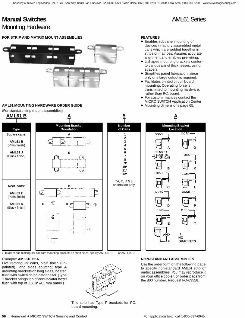
Manual Switches AML61 SeriesMounting Hardware
56 Honeywell 1 MICRO SWITCH Sensing and Control For application help: call 1-800-537-6945.
FOR STRIP AND MATRIX MOUNT ASSEMBLIES FEATURES1 Enables subpanel mounting of
devices in factory assembled metalcans which are welded together instrips or matrices. Assures accuratealignment and enables pre-wiring.
1 L-shaped mounting brackets conformto various panel thicknesses, usingspacers.
1 Simplifies panel fabrication, sinceonly one large cutout is required.
1 Facilitates printed circuit boardmounting. Operating force istransmitted to mounting hardware,rather than P.C. board.
1 For custom matrices contact theMICRO SWITCH Application Center.
1 Mounting dimensions page 65.AML61 MOUNTING HARDWARE ORDER GUIDE(For standard strip mount assemblies)
AML61 B A 5 A
Mounting Bracket Number Mounting BracketType Orientation of Cans Location
Square cans:
AML61 B(Plain finish)
AML61 J(Black finish)
A
E
123456789*
10*11*12*
*A, C, D & Eorientation only.Rect. cans: B
AML61 E(Plain finish)
AML61 K C D(Black finish)
A G
B K
C L
D P
E T
F
UNOBRACKETS
1To order one rectangular can with mounting brackets on short sides, specify AML61EB1 or AML61KB1 .
Example: AML61EC5AFive rectangular cans, plain finish (un-painted), long sides abutting; type Amounting brackets on long sides, locatedflush with switch or indicator bezel. (TypeT bracket brings top of annunciator bezelflush with top of .160 in./4,1 mm panel.)
This strip has Type F brackets for P.C.board mounting.
NON-STANDARD ASSEMBLIESUse the order form on the following pageto specify non-standard AML61 strip ormatrix assemblies. You may reproduce iton your office copier, or order pads fromthe 800 number. Request FO-63558.
Courtesy of Steven Engineering , Inc. ! 230 Ryan Way, South San Francisco, CA 94080-6370 ! Main Office: (650) 588-9200 ! Outside Local Area: (800) 258-9200 ! www.stevenengineering.com

Manual Switches AML71/75 SeriesBarriers/Panel Seal Accessories
For application help: call 1-800-537-6945. Honeywell 1 MICRO SWITCH Sensing and Control 57
AML71 BARRIERS
Drawing shows two switches, slot mount-ed. From left to right: one center barrier, asecond switch, plus another end barrierto complete the arrangement.
When mounting an individual unit, an endbarrier is attached to each side of thehousing. The center barrier is used in aslot mount array.
FEATURES1 Barriers separate individually
mounted switches and indicators —help prevent inadvertent actuation oftwo pushbutton switches with a singlepush.
1 Front of panel mounting simplifiesinstallation.
AML71 BARRIER ORDER GUIDE (See notes)Barriers shown in order guide are black.
Barrier Length Type Catalog Listing
Short Center AML71SCB(For use with square devices and short side
of rectangular devices.) End AML71SEB
Long Center AML71LCB(For use with long side of rectangular
devices.) End AML71LEB
Notes:Not for use with AML61 mounting hardware or any full guard bezel products.Not for use with AML41J, K, or L lens type indicators; or AML45 annunciators.
AML75 PANEL SEAL FEATURES1 AML75 panel seals fit pushbutton
switches and indicators.1 Provides protection from
contamination from accidentalbeverage spills, dust, and dirt.
1 Easy to install, without tools1 No effect on display color, light
intensity, or legend quality.1 Replace seal or change lamps without
removing switch from panel.1 For .19-inch standard height square or
rectangular pushbuttons.1 Mounting dimensions page 66.
The design complements AML’s func-tional appearance, creating a pleasingframed effect around the button. It con-sists of a matte black plastic base whichpress-fits between the panel and switchbezel, and a transparent flexible sealwhich snaps into the base. PK 8521, ship-ped with each order, provides installationinstructions.
Button colors and legends can be viewedwithout distortion whether lighted or un-lighted. Seals can be conveniently re-placed or removed for relamping, withoutremoving the switch from panel.
Operating temperature range is 32° to131°F (0° to 55°C).
AML75 PANEL SEAL ORDER GUIDE
For Use With:
Square .19N Rectangular .19NDescription high pushbuttons high pushbuttons Rockers
Base & Seal AML75ABC AML75BBC AML75RBC
Base Only AML75ABN AML75BBN —
Seal Only AML75ANC AML75BNC —
Notes:Multiple units should not be mounted in asingle slot, since this would create an un-sealed space between each unit. AML75seals are not for use with barriers, full
guard bezels, AML61 mounting hard-ware, AML45 annunciators, or AML41J, K,or L lens type indicators.
MATERIALBase: PolypropyleneCap: Polyvinyl Chloride
Manuals
Courtesy of Steven Engineering , Inc. ! 230 Ryan Way, South San Francisco, CA 94080-6370 ! Main Office: (650) 588-9200 ! Outside Local Area: (800) 258-9200 ! www.stevenengineering.com

Manual Switches AML76/78 SeriesSwitch Guard/Panel Plugs, Dummy Housings
58 Honeywell 1 MICRO SWITCH Sensing and Control For application help: call 1-800-537-6945.
FEATURES1 Button cannot be operated when
switch guard cover is closed,preventing accidental operation
1 Wire lock-down feature furtherprevents unintentional actuation of theswitch.
1 Lamps can be replaced with theswitch guard attached, withoutspecial tools, saving maintenancetime
1 Can be used with alternate ormomentary action square orrectangular .19 inch standard heightAML buttons
1 Shock resistant construction, for long,maintenance-free life
AML76 switch guard protects squareand rectangular .19-inch standardheight pushbuttons from inadvertentactuation. It is for use with standard be-zel type switches only.
See page 66 for mounting dimensions.
The switch guard cover is clear, polycar-bonate thermoplastic through which thebutton is easily visible. The word ‘‘lift’’ ismolded onto the top front edge of theguard. The bracket is bright-finishedstainless steel.
The switch guard may be assembled tothe AML pushbutton before the switch isinstalled in a panel. Or, the guard can beassembled to a pushbutton alreadymounted in a panel, providing the wiringis sufficiently slack to raise the switch be-zel above the panel; and if there is suffi-cient clearance with adjacent units. PK8522 contains installation instructionsand is shipped with each order.
AML switch guards may be mounted inhorizontal or vertical matrices. A wirelock-down feature, using .020-inch diam-eter locking wire, may be used as an addi-tional protection.
SWITCH GUARD ORDER GUIDE
Guard Type* Catalog Listing
Square AML76C10T01P
Rectangular AML76F10T01P* The word ‘‘LIFT’’ is molded into the cover. If other
languages are desired contact the 800 number.Note: Switch guard is not designed for use withAML61 mounting hardware, AML71 barriers, or fullguard bezel switches.
CONNECTOR BLOCK
AML79CC
This connector block can be used withsquare 1 and 2 pole AML21 switches with.110 × .020 terminals to enable plug-inwiring.
AML78 PANEL PLUGS
Plastic panel plugs (shown above) en-able the user to provide for future needsby punching extra panel holes. Finishedin matte black, they are the same heightas the standard AML bezel when snap-ped in place from the panel front.
Panel plugs are only for use in individualholes or with AML61 mounting hardwarein multi-station strips. (Use dummy hous-ings in strip cutouts without AML61mounting hardware.)
PANEL PLUG ORDER GUIDE
Plug Type Catalog Listing
Square AML78CB
Rectangular AML78FB
AML78 DUMMY HOUSINGSDummy housings can be used to providefor expansion needs in strip cutouts with-out AML61 mounting hardware. Theyhave mounting clips, but there is no provi-sion for switching or illumination.
DUMMY HOUSING ORDER GUIDE
CatalogDummy Housing Type* Listing
Square AML78C100(Pushbutton style)
Rectangular AML78F100(Pushbutton style)
Rectangular AML78J100(Lens indicator style)
* Order AML51 Buttons/lenses for use with dummyhousings.
Courtesy of Steven Engineering , Inc. ! 230 Ryan Way, South San Francisco, CA 94080-6370 ! Main Office: (650) 588-9200 ! Outside Local Area: (800) 258-9200 ! www.stevenengineering.com

Manual Switches AML91 SeriesLamps, Soldering Recommendations, Receptacles
For application help: call 1-800-537-6945. Honeywell 1 MICRO SWITCH Sensing and Control 59
AML91 LAMP ORDER GUIDE
Lamp Industry CatalogType Lamp No. Voltage Listing
86 6.3 AML91LA86IncandescentT-1-3/4 73 14.0 AML91LA73
wedge base 85 28.0 AML91LA85
LAMP DATAThe following data was compiled frommanufacturer’s specifications, for refer-ence only.
INCANDESCENT LAMPSIndustry Life
Lamp No. Volts Amps Watts MSCP A/C Volts
86 6.3 .200 1.25 .49 20,000 hours5.5 .185 1.12 .246 106,200 hours5.0 .177 .89 .185 290,000 hours
73 14.0 .080 1.12 .30 15,000 hours12.0 .077 1.00 .23 36,450 hours
85 28.0 .04 1.12 .30 7,000 hours24.0 .037 .89 .177 41,860 hours
Neon Lamps25,000 hours (half life)
INTEGRAL LEDs
Peak Inverse Voltagew/o Diode w/Diode
LEDs FurnishedPermanentlyInstalled in
These Products Vf If VPD Protection Protection
AML12, 15, 16, 2.4 V 20 mA .7 V 5 V 34 V22, 25, 26, 42
AML45 2.4 V 20 mA .7 V 4 V 33 V
100,000 hours (half life).
AML92 SERIES LEDs
For use with these AML switches and in-dicators equipped with lamp sockets:Pushbutton switches: AML11 (SquareOnly)*, AML21 (rectangular and square),and AML31.Paddle switches: AML31/23/33Rocker switches: AML14/24/34Indicators: AML41* Rectangular solid state with one or two lamp circuitscannot be used with LED catalog listings ending in‘‘L’’.
OPERATING CHARACTERISTICSVF Fwd. Voltage (typ.)
Type Yellow Green Red WhiteIF Fwd.Current
VR Rev.Voltage
Quad Chip 8.6 8.6 7.8 — 15 mA 16 V
Six Chip 4 V 4 V 4 V 4 V 50 mA 5.6 V
TEMPERATURE RANGE(Quad Chip or Six Chip)Operating: –20 to 60°C (–4 to 140°F)Storage: –30 to 100°C (–22 to 212°F)
AML92 ORDER GUIDE
LED Color Quad Chip Six Chip
Red AML92ERY AML92ERL
Green AML92EGY AML92EGL
Yellow AML92EYY AML92EYL
White — AML92EWL** For use with white or yellow buttons.
SOLDERING RECOMMENDATIONSAll terminals are solder plated. Proper sol-dering and cleaning procedures must befollowed to maintain the reliability of AMLproducts during installation. An instruc-tion sheet which outlines these proce-dures is included with AML shipments.You may also obtain a copy from yourMICRO SWITCH Sales Office. RequestPK 8518.
As a general guide, the following informa-tion may be used:
Use a 280°C (538°F) solder iron tip, up to6 seconds duration, with a 60-40 rosincore solder. This allows the terminal toheat quickly on the exterior of the housingonly, and greatly reduces the chance offlux migrating inside the housing.
LED APPLICATION INFORMATIONFor those devices without internal currentlimiting resistors, suitable external controlof the LED current must be provided. It isrecommended that a minimum of 5 VDCopen circuit voltage with an appropriateseries resistance be used to drive LED de-vices. This minimizes the effect of temper-ature (current variation) on forward volt-age of the LED.
Resistor values can be determined bysupply voltage or current for LED:
RS JE – Vf
If
WHERE: RS J Series ResistanceE J Supply VoltageVf J Forward Voltage of LEDIf J Circuit Current
If a diode is added in series for reverse po-larity protection then:
RS JE – Vf – VPD
If
WHERE: VPD Forward Voltage ofProtection Diode
Manuals
Courtesy of Steven Engineering , Inc. ! 230 Ryan Way, South San Francisco, CA 94080-6370 ! Main Office: (650) 588-9200 ! Outside Local Area: (800) 258-9200 ! www.stevenengineering.com
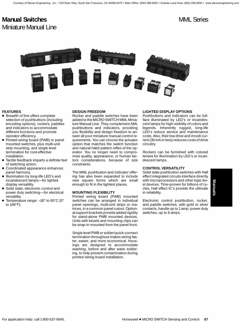
Manual Switches MML SeriesMiniature Manual Line
For application help: call 1-800-537-6945. Honeywell 1 MICRO SWITCH Sensing and Control 67
FEATURES1 Breadth of line offers complete
selection of pushbuttons (includingencoding options), rockers, paddlesand indicators to accommodatedifferent functions and promoteoperator efficiency.
1 Printed wiring board (PWB) or panelmounted switches, plus multi-unitstrip mounting, and single leveltermination for cost-effectiveinstallation.
1 Tactile feedback imparts a definite feelof switching action.
1 Coordinated appearance enhancespanel harmony.
1 Illumination by long-life LED’s andincandescent lamps—for lighteddisplay versatility.
1 Solid state, electronic control andpower duty switching—for electricalversatility.
1 Temperature range: –18° to 65°C (0°to 149°F).
DESIGN FREEDOMRocker and paddle switches have beenadded to the MICRO SWITCH MML Minia-ture Manual Line. They complement AMLpushbuttons and indicators, providingyou flexibility and design freedom to an-swer all your miniature manual control re-quirements. You can choose the actuatoroption that matches the switch functionand natural habit pattern reflex of the op-erator. You no longer need to compro-mise quality, appearance, or human fac-tors considerations, because of sizeconstraints.
The MML pushbutton and indicator offer-ing has also been expanded to includenew square forms which are smallenough to fit in the tightest places.
MOUNTING FLEXIBILITYPrinted wiring board (PWB) mountedswitches can be arranged in individualpanel openings, multi-unit strips or ma-trices, in a common panel cutout. Option-al support brackets provide added rigidityfor stand-alone PWB mounted devices.Units with bezels and mounting clips canbe snap-in mounted from the panel front.
Single level PWB or solder/quick-connecttermination throughout makes wiring fas-ter, easier, and more economical. Hous-ings are designed to accommodatewashing, before and after wave solder-ing, to help prevent contamination duringprinted wiring board installation.
LIGHTED DISPLAY OPTIONSPushbuttons and indicators can be full-face illuminated by LED’s or incandes-cent lamps for high visibility of colors andlegends. Inherently rugged, long-lifeLED’s reduce service and maintenancecosts. Also, their low drive and inrush cur-rent (30 mA or less) reduces costs of drivecircuitry.
Rockers can be furnished with coloredlenses for illumination by LED’s or incan-descent lamps.
CONTROL VERSATILITYSolid state pushbutton switches with Halleffect integrated circuits interface directlywith microprocessors and other logic lev-el devices. Time-proven for billions of cy-cles, Hall effect IC’s provide the ultimatein reliability.
Electronic control pushbutton, rocker,and paddle switches, with gold or silvercontacts, handle up to 1 amp; power dutyswitches, up to 6 amps.
Manuals
Courtesy of Steven Engineering , Inc. ! 230 Ryan Way, South San Francisco, CA 94080-6370 ! Main Office: (650) 588-9200 ! Outside Local Area: (800) 258-9200 ! www.stevenengineering.com

Manual Switches MML SeriesMiniature Manual Line
68 Honeywell 1 MICRO SWITCH Sensing and Control For application help: call 1-800-537-6945.
MML ENHANCES PANEL HARMONYThe attractive clean line design of the totalMML offering is coordinated to work inharmony and enhance the visual qualitiesof your product. MML will help make agood first impression with your custom-ers by blending with other panel compo-nents. And also work hard over the longrun to maintain operator satisfaction.
HOW TO ORDERTo specify MML catalog listings, refer tothe order guides. They are based on amodular cataloging system which givesyou the flexibility to choose the combina-tion of feature options that best answersthe requirements of your application.
ORDER GUIDES
Solid State SwitchesMML11 Pushbutton Switches . . . . . . . . . . . . . . . . . . . . . . . . . . . . . . . . . . . . . . . . . . 70
Electronic Control SwitchesMML21 Pushbutton Switches . . . . . . . . . . . . . . . . . . . . . . . . . . . . . . . . . . . . . . . . . . 72MML23 Paddle Switches . . . . . . . . . . . . . . . . . . . . . . . . . . . . . . . . . . . . . . . . . . . . . . 74MML24 Rocker Switches . . . . . . . . . . . . . . . . . . . . . . . . . . . . . . . . . . . . . . . . . . . . . . 74
Power Duty SwitchesMML31 Pushbutton Switches . . . . . . . . . . . . . . . . . . . . . . . . . . . . . . . . . . . . . . . . . . 76
IndicatorsMML41 Indicators/LED or Incandescent Display . . . . . . . . . . . . . . . . . . . . . . . . . . 78MML46 Indicators/LED or Incandescent Display . . . . . . . . . . . . . . . . . . . . . . . . . . 78MML44 Indicators/LED Display. . . . . . . . . . . . . . . . . . . . . . . . . . . . . . . . . . . . . . . . . 80
Lenses and ButtonsMML51 Lenses/Incandescent or Non-lighted Display. . . . . . . . . . . . . . . . . . . . . . 82MML52 Lenses/LED or Neon Display . . . . . . . . . . . . . . . . . . . . . . . . . . . . . . . . . . . 82
Mounting HardwareMML61 Strip Mounting Frames . . . . . . . . . . . . . . . . . . . . . . . . . . . . . . . . . . . . . . . . . 85MML72/73 Bezels and Mounting Clips . . . . . . . . . . . . . . . . . . . . . . . . . . . . . . . . . . 86MML74 PWB Mount Support Brackets . . . . . . . . . . . . . . . . . . . . . . . . . . . . . . . . . . 86
LED’s, Lamps, ReceptaclesMML92/93 LED’s/Receptacles . . . . . . . . . . . . . . . . . . . . . . . . . . . . . . . . . . . . . . 87/90MML91/93 Incandescent Lamps/Receptacles . . . . . . . . . . . . . . . . . . . . . . . . . 89/90
MML medical application. Intranvaneous fluid flow controller auto-matically dispenses fluids for medications, therapy, and nutrition.
MML communications application. Mobile radio control keeps busi-nesses in touch with employees on the road.
Courtesy of Steven Engineering , Inc. ! 230 Ryan Way, South San Francisco, CA 94080-6370 ! Main Office: (650) 588-9200 ! Outside Local Area: (800) 258-9200 ! www.stevenengineering.com

Manual Switches MML SeriesMiniature Manual Line
For application help: call 1-800-537-6945. Honeywell 1 MICRO SWITCH Sensing and Control 69
MML CHARACTERISTICSMML 10 Series MML 20 Series MML 30 Series MML 40 Series
Mechanical Lifetime* N/APushbuttons–Momentary 1,000,000 250,000 100,000 ---Pushbuttons–Alternate 100,000 100,000 100,000 ---Rockers 100,000 250,000 100,000 ---Paddles 100,000 250,000 100,000 ---
Electrical Lifetime*** N/APushbuttons–Momentary 1,000,000 25,000 25,000 ---Pushbuttons–Alternate 100,000 25,000 25,000 ---Rockers 100,000 25,000 25,000 ---Paddles 100,000 25,000 25,000 ---
Agency RatingsUL File E53576 File E12252 File E12252 File E58932CSA File L R4442 File LR4442 File LR4442 File LR4442
*95% Survival**Lifetime at Full Rated Load
MML ELECTRICAL DATAMML10 SERIESElectrical Characteristics Integrated Circuit Function 5-24 VDC Sinking
Supply Current (Max.) 7 mA (Released)8 mA (Operated no load)
Output Voltage (Operated) 0.3 Volt (Sinking 10 mA)
Output Leakage Current 5.0 µAMax. (Released)
Switching Time Max.Rise 10% to 90% 1.5 µ sec (Sinking 10 mA)Fall 90% to 10% 0.5 µ sec (Sinking 10 mA)
Rated Output Current 10 mA Sinking
Absolute MaximumRatings
Supply Voltage (Vs) –28 to +28 VDC
Voltage Externally Applied –0.5 Volt min.to Output +28 Volts max.
(Off condition)
Loads to Output 20 mA (Sinking)
Storage Temperature –40° to +85°C(–40° to +185°F)
Operating Temperature –18° to +65°C(0° to +149°F)and supply voltage of 4.5to 5.5 VDC
As with all solid state components, performance can be expected to deteriorate as rating limits are approached;however, they will not be damaged unless the limits are exceeded.
MML20 SERIESElectrical Rating(silver contacts)
Standard buttonsUp to 1 amp, 125 VAC
1 piece plunger/lens cap buttons:Black—Up to 1 amp, 125 VACAll others—Up to 0.5 amp, 125 VAC
Electrical RatingGold Contacts
All button styles:Up to 0.25 amp, 30 VDCUL rating—0.10 amp, 30 VDC
One pole Form C
MML30 SERIESMML31:Electrical RatingSilver Contacts
6A @ 125 VAC, 250 VAC; 2A @ 30 VDC;1A @ 125 VDC ‘‘L’’; 1/10 hp @ 125 VAC
Contact Arrangement 1 or 2 poles Form X
Manuals
Courtesy of Steven Engineering , Inc. ! 230 Ryan Way, South San Francisco, CA 94080-6370 ! Main Office: (650) 588-9200 ! Outside Local Area: (800) 258-9200 ! www.stevenengineering.com

Manual Switches MML SeriesMiniature Manual Line
For application help: call 1-800-537-6945. Honeywell 1 MICRO SWITCH Sensing and Control 91
MOUNTING DIMENSIONS (For reference only)
PANEL CUTOUTS FOR PUSHBUTTON SWITCHES AND INDICATORS/RECTANGULAR TYPE
INDIVIDUAL SNAP-IN PANEL MOUNT
1,27 — 2,39
.050 — .094
Panel Thickness
PANEL PUNCH FOR MML SERIESA panel punch is manufactured by Greenlee-Textron Tool Co., Rockford, IL(815-926-3011).
INDIVIDUAL PRINTED WIRING BOARD (PWB) MOUNT
Pushbutton Plunger Thru Panel Housing Thru Panel Indicator Lens Thru Panel
MULTI-UNIT PRINTED WIRING BOARD (PWB) MOUNT
Horizontal Mount
Establish tooling holes on X coordinate and use these holes to establishrelationship between PWB and Panel
Terminals x0,20 0,76
.008 .030
Recommended hole size in PWB 1,17
.046
Switches must be fixtured to insure proper panel cutout alignment
N = Number of switches
X = N-1 x +15,24 15,11.600 .595
Y =10,16
.400
Example: N = 5 Switches
X = 5-1 x +15,24 15,11.600 .595
X = 76,07
2.995
Matrix Mount Vertical Mount
N = Number of SwitchesNX = Number of RowsNY = Number of Columns
N = NX–1 x +15,24 15,11.600 .595
Y = NY x 10,16
.400
N = Number of Switches
Y = N x 10,16.400
X = 15,11.595
Example: N = 4Y = 4 x 10,16
.400
Y = 40,641,600
Manuals
Courtesy of Steven Engineering , Inc. ! 230 Ryan Way, South San Francisco, CA 94080-6370 ! Main Office: (650) 588-9200 ! Outside Local Area: (800) 258-9200 ! www.stevenengineering.com

Manual Switches MML SeriesMiniature Manual Line
92 Honeywell 1 MICRO SWITCH Sensing and Control For application help: call 1-800-537-6945.
MOUNTING DIMENSIONS (For reference only)
PANEL CUTOUTS FOR PUSHBUTTON SWITCHES AND INDICATORS/SQUARE TYPE
Individual Snap-inPanel Mount Individual Printed Wiring Board PWB Mount
Pushbutton Plunger Thru Panel Housing Thru Panel Indicator Lens Thru Panel
See page 91 for panel punch manufacturer.
MULTI-UNIT PRINTED WIRING BOARD (PWB) MOUNT
Horizontal Mounting
Establish tooling holes on X coordinate and use these holes to establishrelationship between PWB and Panel
Terminals x0,20 0,76
.008 .030
Recommended hole size in PWB 1,17
.046
Switches must be fixtured to insure proper panel cutout alignment
Formula:N = Number of switches
X = N x10,16.400
Y =10,16
.400
Example: N = 5 Switches
X = 5 x 10,16.400
X = 50,80
2.00
Matrix Mounting Vertical Mounting
N = Number of SwitchesNX = Number of RowsNY = Number of Columns
Formula: X = N x10,16.400
Y = N x 10,16
.400
N = Number of Switches
Formula: Y = N x 10,16.400
X = 10,16.400
Example: N = 4Y = 4 x 10,16
.400
Y = 40,641.600
Courtesy of Steven Engineering , Inc. ! 230 Ryan Way, South San Francisco, CA 94080-6370 ! Main Office: (650) 588-9200 ! Outside Local Area: (800) 258-9200 ! www.stevenengineering.com

Manual Switches MML SeriesMiniature Manual Line
For application help: call 1-800-537-6945. Honeywell 1 MICRO SWITCH Sensing and Control 93
MOUNTING DIMENSIONS (For reference only)
PRINTED WIRING BOARD MOUNT PUSHBUTTON SWITCHES/RECTANGULAR TYPEMML11 Switches PWB Pin Locations
PWB Receptacle Installed (LED or Incandescent Lamp)
MML21 Switches PWB Pin Locations
PWB Receptacle Installed (LED or Incandescent Lamp)
Notes:Micro Switch Identification This Side
2 – Linear measure mm/IN. or mmIN.
MML31 Switches
Manuals
Courtesy of Steven Engineering , Inc. ! 230 Ryan Way, South San Francisco, CA 94080-6370 ! Main Office: (650) 588-9200 ! Outside Local Area: (800) 258-9200 ! www.stevenengineering.com
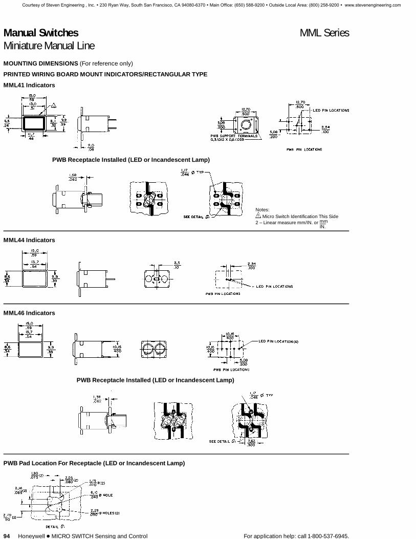
Manual Switches MML SeriesMiniature Manual Line
94 Honeywell 1 MICRO SWITCH Sensing and Control For application help: call 1-800-537-6945.
MOUNTING DIMENSIONS (For reference only)
PRINTED WIRING BOARD MOUNT INDICATORS/RECTANGULAR TYPE
MML41 Indicators
PWB Receptacle Installed (LED or Incandescent Lamp)
Notes:Micro Switch Identification This Side
2 – Linear measure mm/IN. or mmIN.
MML44 Indicators
MML46 Indicators
PWB Receptacle Installed (LED or Incandescent Lamp)
PWB Pad Location For Receptacle (LED or Incandescent Lamp)
Courtesy of Steven Engineering , Inc. ! 230 Ryan Way, South San Francisco, CA 94080-6370 ! Main Office: (650) 588-9200 ! Outside Local Area: (800) 258-9200 ! www.stevenengineering.com

Manual Switches MML SeriesMiniature Manual Line
For application help: call 1-800-537-6945. Honeywell 1 MICRO SWITCH Sensing and Control 95
MOUNTING DIMENSIONS (For reference only)
PANEL MOUNT PUSHBUTTON SWITCHES/RECTANUGLAR TYPE
MML21 Switches
Solder Receptacle Installed (LED or Incandescent Lamp)
Notes:Micro Switch Identification This Side
2 – Linear measure mm/IN. or mmIN.
Rotate 45° counter clockwise for removalfrom switch or indicator
MML31 Switches Terminal Detail
Manuals
Courtesy of Steven Engineering , Inc. ! 230 Ryan Way, South San Francisco, CA 94080-6370 ! Main Office: (650) 588-9200 ! Outside Local Area: (800) 258-9200 ! www.stevenengineering.com

Manual Switches MML SeriesMiniature Manual Line
96 Honeywell 1 MICRO SWITCH Sensing and Control For application help: call 1-800-537-6945.
MOUNTING DIMENSIONS (For reference only)
PANEL MOUNT INDICATORS/RECTANGULAR TYPE
MML41 Indicators
Solder Receptacle Installed (LED or Incandescent Lamp)
MML43 Indicators Terminal Detail
Notes:Micro Switch Identification This Side
2 – Linear measure mm/IN. or mmIN.
MML44 Indicators
MML46 Indicators
Solder Receptacle Installed (LED or Incandescent Lamp)
Courtesy of Steven Engineering , Inc. ! 230 Ryan Way, South San Francisco, CA 94080-6370 ! Main Office: (650) 588-9200 ! Outside Local Area: (800) 258-9200 ! www.stevenengineering.com

Manual Switches MML SeriesMiniature Manual Line
For application help: call 1-800-537-6945. Honeywell 1 MICRO SWITCH Sensing and Control 97
MOUNTING DIMENSIONS (For reference only)
PRINTED WIRING BOARD MOUNT PUSHBUTTON SWITCHES AND INDICATORS/SQUARE TYPE
MML21 Switches
PWB Receptacle Installed (LED or Incandescent Lamp)
MML46 Indicators
PWB Receptacle Installed (LED or Incandescent Lamp)
NOTESMICRO SWITCH IDENTIFICATION THIS SIDEMML41: 2,0/.08MML46: 1,0/.04
3–LINEAR MEASURE mm/IN OR mmIN
PANEL MOUNT PUSHBUTTON SWITCHES/SQUARE TYPE
MML21 Switches Termination Detail
NOTE:To install LED or lamp, use MML93L receptacle shown on page 90.
Manuals
Courtesy of Steven Engineering , Inc. ! 230 Ryan Way, South San Francisco, CA 94080-6370 ! Main Office: (650) 588-9200 ! Outside Local Area: (800) 258-9200 ! www.stevenengineering.com

Manual Switches MML SeriesMiniature Manual Line
98 Honeywell 1 MICRO SWITCH Sensing and Control For application help: call 1-800-537-6945.
MOUNTING DIMENSIONS (For reference only)
LENSES
RectangularPushbutton Lens
RectangularIndicator Lens
SquarePushbutton Lens
SquareIndicator Lens
PWB SUPPORT BRACKETS
Rectangular Square
Courtesy of Steven Engineering , Inc. ! 230 Ryan Way, South San Francisco, CA 94080-6370 ! Main Office: (650) 588-9200 ! Outside Local Area: (800) 258-9200 ! www.stevenengineering.com

Manual Switches MML SeriesMiniature Manual Line
For application help: call 1-800-537-6945. Honeywell 1 MICRO SWITCH Sensing and Control 99
MOUNTING DIMENSIONS (For reference only)
PANEL CUTOUTS FOR PWB MOUNT PADDLE AND ROCKER SWITCHES
Actuator Housing Umbrella Rocker 2-Pole 2-PoleThru Panel Thru Panel Thru Panel MML33, 34 Actuator MML33, 34
Thru Panel Housing Thru PanelSee page 91 for panel punch manufacturer.
PRINTED WIRING BOARD MOUNT PADDLE AND ROCKER SWITCHES
MML23 Paddle Switches
See MML24 drawing below for PWB receptacle dimensions
MML24 Rocker Switches
With PWB Receptacle Installed (LED or Incandescent Lamp)
MML24 Rocker (Umbrella Type) Switches
Notes:Micro Switch Identification This Side
2 – Linear measure mm/IN. or mmIN.
Manuals
Courtesy of Steven Engineering , Inc. ! 230 Ryan Way, South San Francisco, CA 94080-6370 ! Main Office: (650) 588-9200 ! Outside Local Area: (800) 258-9200 ! www.stevenengineering.com

Manual Switches MML SeriesMiniature Manual Line
100 Honeywell 1 MICRO SWITCH Sensing and Control For application help: call 1-800-537-6945.
MOUNTING DIMENSIONS (For reference only)
PANEL MOUNT PADDLE AND ROCKER SWITCHES
MML23 Paddle Switches
Notes:Micro Switch Identification This Side
2 – Linear measure mm/IN. or mmIN.
MML24 Rocker Switches
NOTE:To install LED or lamp, use MML93R recepta-cle shown on page 89.
Courtesy of Steven Engineering , Inc. ! 230 Ryan Way, South San Francisco, CA 94080-6370 ! Main Office: (650) 588-9200 ! Outside Local Area: (800) 258-9200 ! www.stevenengineering.com

Manual Switches MML SeriesMiniature Manual Line
For application help: call 1-800-537-6945. Honeywell 1 MICRO SWITCH Sensing and Control 101
MOUNTING DIMENSIONS (For reference only)
HORIZONTAL MATRIX MOUNT/RECTANGULAR TYPEPrinted Wiring Board
Panel Mounting Detail Mounting Detail
Recommended Panel Cutout
10 127,00/5.000 124,56/4.904 10 188,14/7.407 180,64/7.112
9 114,30/4.500 111,86/4.404 9 170,36/6.707 162,86/6.412
8 101,60/4.000 99,16/3.904 8 152,58/6.007 145,08/5.712
7 88,90/3.500 86,46/3.404 7 134,80/5.307 127,30/5.012
6 76,20/3.000 73,76/2.904 6 117,02/4.607 109,52/4.312
5 63,50/2.500 61,06/2.404 5 99,24/3.907 91,74/3.612
4 50,80/2.000 48,36/1.904 4 81,46/3.207 73,96/2.912
3 38,10/1.500 35,66/1.404 3 63,68/2.507 56,18/2.212
2 25,40/1.000 22,96/ .904 2 45,90/1.807 38.40/1.512
1 12,45/ 0.49 10,26/0.404 N/A N/A N/A
NO. OF NO. OFSTRIPS W X STATIONS Y Z
Notes:1 – Linear measure mm/IN. or mm
IN.
Manuals
Courtesy of Steven Engineering , Inc. ! 230 Ryan Way, South San Francisco, CA 94080-6370 ! Main Office: (650) 588-9200 ! Outside Local Area: (800) 258-9200 ! www.stevenengineering.com

Manual Switches MML SeriesMiniature Manual Line
102 Honeywell 1 MICRO SWITCH Sensing and Control For application help: call 1-800-537-6945.
MOUNTING DIMENSIONS (For reference only)
VERTICAL MATRIX MOUNT/RECTANGULAR TYPEPrinted Wiring Board
Panel Mounting Detail Mounting Detail
Recommended Panel Cutout
RECOMMENDED DIMENSIONS
10 177,80/7.000 175,26/6.900 10 137,34/5.407 129,69/5.106
9 160,02/6.300 157,48/6.200 9 124,64/4.907 116,99/4.606
8 142,24/5.600 139,70/5.500 8 111,94/4.407 104,29/4.106
7 124,46/4.900 121,92/4.800 7 99,24/3.907 91,59/3.606
6 106,68/4.200 104,14/4.100 6 86,54/3.407 78,80/3.106
5 88,90/3.500 86,36/3.400 5 73,84/2.907 66,19/2.606
4 71,12/2.800 68,58/2.700 4 61,14/2.407 53,49/2.106
3 53,34/2.100 50,80/2.000 3 48,44/1.907 40,79/1.606
2 35,56/1.400 33,02/1.300 2 35,74/1.407 28,09/1.106
1 17,78/ .700 15,24/ .600 1 23,04/ .907 15,39/ .606
NO. OF NO. OFSTRIPS W X STATIONS Y Z
Notes:1 – Linear measure mm/IN. or mm
IN.
Courtesy of Steven Engineering , Inc. ! 230 Ryan Way, South San Francisco, CA 94080-6370 ! Main Office: (650) 588-9200 ! Outside Local Area: (800) 258-9200 ! www.stevenengineering.com

Manual Switches MML SeriesMiniature Manual Line
For application help: call 1-800-537-6945. Honeywell 1 MICRO SWITCH Sensing and Control 103
MOUNTING DIMENSIONS (For reference only)
MATRIX MOUNT/SQUARE TYPEPrinted Wiring Board
Panel Mounting Detail Mounting Detail
RECOMMENDED DIMENSIONS
10 127,00/5.000 124,56/4.904 10 137,16/5.400 129,84/5.112
9 114,30/4.500 111,86/4.404 9 124,46/4.900 117,14/4.612
8 101,60/4.000 99,16/3.904 8 111,76/4.400 104,44/4.112
7 88,90/3.500 86,46/3.404 7 99,06/3.900 91,74/3.612
6 76,20/3.000 73,76/2.904 6 86,36/3.400 79,04/3.112
5 63,50/2.500 61,06/2.404 5 73,66/2.900 66,34/2.612
4 50,80/2.000 48,36/1.904 4 60,96/2.400 53,64/2.112
3 38,10/1.500 35,66/1.404 3 48,26/1.900 40,94/1.612
2 25,40/1.000 22,96/ .904 2 35,56/1.400 28,24/1.112
1 12,70/ .500 10,26/ .404 1 22,86/ .900 15,54/ .612
NO. OF NO. OFSTRIPS W X STATIONS Y Z
Notes:1 – Linear measure mm/IN. or mm
IN.
Manuals
Courtesy of Steven Engineering , Inc. ! 230 Ryan Way, South San Francisco, CA 94080-6370 ! Main Office: (650) 588-9200 ! Outside Local Area: (800) 258-9200 ! www.stevenengineering.com

Manual Switches MML11 SeriesSolid State Pushbutton
70 Honeywell 1 MICRO SWITCH Sensing and Control For application help: call 1-800-537-6945.
LED, INCANDESCENT, OR NON-LIGHTED DISPLAY
PWB Mount Panel Mount
FEATURES1 Hall effect reliability1 Provides low voltage signals that
interface with nearly all DC logic1 Accepts one LED or incandescent
lamp1 Printed wiring board or snap-in panel
mounting1 UL recognized, CSA certified1 Bezels and mounting clips, LEDs and
legended lenses can be furnishedinstalled or ordered separately
Example: MML11KA3AAKSolid state pushbutton housing (black),no bezel; PWB terminals; momentary ac-tion; 5 VDC, current sinking output, blackplunger.
Example: MML11KK3AAKRSDRAs above, except furnished with black be-zel; mounting clips (long sides); red LED,and red lens installed.
MML11 ORDER GUIDECatalog listing codes for switch,less assembled display options
MML11K A 3 AA
Housing Type(Rectangular) Mounting Terminals Circuitry/Action
MML11KBlack housing
A No bezel (PWBmounting)
K Black bezel, mtg.clip/long sides
3 Printed wiring board AA 5-24 VDC sinkingmom. action
Courtesy of Steven Engineering , Inc. ! 230 Ryan Way, South San Francisco, CA 94080-6370 ! Main Office: (650) 588-9200 ! Outside Local Area: (800) 258-9200 ! www.stevenengineering.com
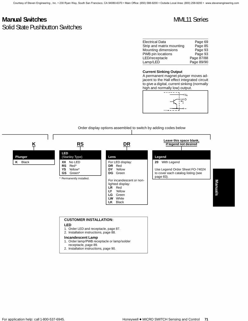
Manual Switches MML11 SeriesSolid State Pushbutton Switches
For application help: call 1-800-537-6945. Honeywell 1 MICRO SWITCH Sensing and Control 71
Electrical Data Page 69Strip and matrix mounting Page 85Mounting dimensions Page 93PWB pin locations Page 93LED/receptacle Page 87/88Lamp/LED Page 89/90
Current Sinking OutputA permanent magnet plunger moves ad-jacent to the Hall effect integrated circuitto give a digital, current sinking (normallyhigh and normally low) output.
Order display options assembled to switch by adding codes below
K RS DRLeave this space blank,
if legend not desired
PlungerLED(Stanley Type) Lens Legend
K Black XX No LEDRS Red*YS Yellow*GS Green*
* Permanently installed.
For LED display:DR RedDY YellowDG Green
For incandescent or non-lighted display:LR RedLY YellowLG GreenLW WhiteLK Black
20 With Legend
Use Legend Order Sheet FO-74024to cover each catalog listing (seepage 83).
CUSTOMER INSTALLATION:LED1. Order LED and receptacle, page 87.2. Installation instructions, page 88.
Incandescent Lamp1. Order lamp/PWB receptacle or lamp/solder
receptacle, page 89.2. Installation instructions, page 90.
Manuals
Courtesy of Steven Engineering , Inc. ! 230 Ryan Way, South San Francisco, CA 94080-6370 ! Main Office: (650) 588-9200 ! Outside Local Area: (800) 258-9200 ! www.stevenengineering.com

Manual Switches MML21 SeriesElectronic Control Pushbutton
72 Honeywell 1 MICRO SWITCH Sensing and Control For application help: call 1-800-537-6945.
LED, INCANDESCENT, OR NON-LIGHTED DISPLAY
PWB Mount Panel Mount(Standard plunger) (Standard plunger)
PWB Mount(One-piece plunger)
FEATURES1 Silver or gold contacts1 Choice of rectangular or square
housings1 Accepts one LED or incandescent
lamp1 Printed wiring board or snap-in panel
mounting1 Bezels and mounting clips, LEDs and
legended lenses can be furnishedinstalled or ordered separately
1 UL recognized, CSA certified
Example: MML21KK3AAKElectronic control pushbutton switch withstandard plunger; rectangular housing(black); bezel (black); mounting clips onlong sides, PWB terminals; 1-pole, mo-mentary action, silver contacts, blackplunger.
Example: MML21KK3AAKRSDRAs above, except furnished with red LEDand red lens installed.
MML21KK3AAHRSXX20 as above, leg-ended.
MML21 STANDARD PLUNGER SWITCHES ORDER GUIDECatalog listing codes for switch, less assembled display options
MML21K K 3 AA
Housing Type Mounting Terminals Circuitry/Action (Each pole is double throw)
Rectangular Square Rectangular Square
MML21KRectangular Black HousingMML21HSquare Black Housing
A No bezel (PWBmounting)
K Black bezel, mtg.clip/long sides
A No bezel (PWBmounting)
R Black bezel& mtg. clip
3 PrintedWiringBoard
2 Solder
Silver Contacts:AA 1 pole,
mom. actionAB 1 pole,
alt. actionAC 2 pole,
mom. actionAD 2 pole,
alt. actionGold Contacts:BA 1 pole,
mom. actionBB 1 pole,
alt. actionBC 2 pole,
mom. actionBD 2 pole,
alt. action
Silver contacts:AA 1-pole,
mom. actionAB 1-pole,
alt. action
Gold contactsBA 1-pole,
mom. actionBB 1-pole,
alt. action
MML21 ONE PIECE LENS/PLUNGER SWITCHES ORDER GUIDE Catalog listing codes for switch, less assembled display options
MML21H K 3 AA
Housing Type Mounting Terminals Circuitry/Action (Each pole is double throw)
Rectangular Square Rectangular Square
MML21KRectangular Black HousingMML21HSquare Black Housing
A No bezel (PWBmounting)
K Black bezel, mtg.clip/long sides
A No bezel (PWBMounting)
R Black bezel& mtg. clip
3 PrintedWiringBoard
2 Solder
Silver Contacts:AA 1 pole,
mom. actionAB 1 pole,
alt. actionAC 2 pole,
mom. actionAD 2 pole,
alt. actionGold Contacts:BA 1 pole,
mom. actionBB 1 pole,
alt. actionBC 2 pole,
mom. actionBD 2 pole,
alt. action
Silver contacts:AA 1-pole,
mom. actionAB 1-pole,
alt. action
Gold contactsBA 1-pole,
mom. actionBB 1-pole,
alt. action
Courtesy of Steven Engineering , Inc. ! 230 Ryan Way, South San Francisco, CA 94080-6370 ! Main Office: (650) 588-9200 ! Outside Local Area: (800) 258-9200 ! www.stevenengineering.com
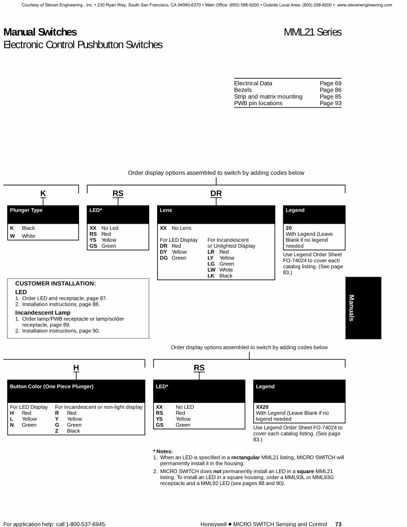
Manual Switches MML21 SeriesElectronic Control Pushbutton Switches
For application help: call 1-800-537-6945. Honeywell 1 MICRO SWITCH Sensing and Control 73
Electrical Data Page 69Bezels Page 86Strip and matrix mounting Page 85PWB pin locations Page 93
Order display options assembled to switch by adding codes below
K RS DR
Plunger Type LED* Lens Legend
K Black
W White
XX No LedRS RedYS YellowGS Green
XX No Lens
For LED DisplayDR RedDY YellowDG Green
For Incandescentor Unlighted DisplayLR RedLY YellowLG GreenLW WhiteLK Black
20With Legend (LeaveBlank if no legendneeded
Use Legend Order SheetFO-74024 to cover eachcatalog listing. (See page83.)
CUSTOMER INSTALLATION:LED1. Order LED and receptacle, page 87.2. Installation instructions, page 88.
Incandescent Lamp1. Order lamp/PWB receptacle or lamp/solder
receptacle, page 89.2. Installation instructions, page 90.
Order display options assembled to switch by adding codes below
H RS
Button Color (One Piece Plunger) LED* Legend
For LED DisplayH RedL YellowN Green
For Incandescent or non-light displayR RedY YellowG GreenZ Black
XX No LEDRS RedYS YellowGS Green
XX20With Legend (Leave Blank if nolegend needed
Use Legend Order Sheet FO-74024 tocover each catalog listing. (See page83.)
*Notes:1. When an LED is specified in a rectangular MML21 listing, MICRO SWITCH will
permanently install it in the housing.
2. MICRO SWITCH does not permanently install an LED in a square MML21listing. To install an LED in a square housing, order a MML93L or MML93Greceptacle and a MML92 LED (see pages 88 and 90).
Manuals
Courtesy of Steven Engineering , Inc. ! 230 Ryan Way, South San Francisco, CA 94080-6370 ! Main Office: (650) 588-9200 ! Outside Local Area: (800) 258-9200 ! www.stevenengineering.com

Manual Switches MML23/24 SeriesElectronic Control Paddle
74 Honeywell 1 MICRO SWITCH Sensing and Control For application help: call 1-800-537-6945.
NON-LIGHTED DISPLAY
PWB Mount Panel Mount
FEATURES1 Printed circuit board or snap-in panel
mounting1 Bezels and mounting clips can be
furnished installed or orderedseparately
1 UL recognized, CSA certified
Example: MML23KA3AA01KElectronic control paddle switch withblack housing; printed wiring boardmounting; printed wiring board terminals;1 pole, silver contacts; 2-position, main-tained action; one circuit ON in each posi-tion; black paddle.
MML23 ORDER GUIDE
MML23K A 3 AA
Housing Type Mounting Terminals Circuitry
MML23KBlack housing
A No bezel (PWB mounting)K Black bezel, mtg. clip/long sides
3 Printed wiring board2 Solder
Insert code lettersfrom Circuitry Chart
Electronic Control Rocker Switches MML24LED, INCANDESCENT, OR NON-LIGHTED DISPLAY
PWB Mount Panel Mount PWB Mount(Lighted rocker)
PWB Mount(Umbrella rocker)
FEATURES1 Accepts one or two LEDs or
incandescent lamps which areordered separately
1 Printed wiring board mounting orsnap-in panel mounting
1 Bezels and mounting clips can befurnished installed or orderedseparately
1 UL recognized, CSA certified
MML24 ORDER GUIDE (Catalog listing for switch, less assembled display options)
MML24K A 3 AAHousing Type Mounting Terminals Circuitry
MML24KBlack housing
A No bezel (PWB mounting)K Black bezel, mtg. clip/long sides
3 Printed wiring board2 Solder
Insert code lettersfrom Circuitry Chart
Courtesy of Steven Engineering , Inc. ! 230 Ryan Way, South San Francisco, CA 94080-6370 ! Main Office: (650) 588-9200 ! Outside Local Area: (800) 258-9200 ! www.stevenengineering.com

Manual Switches MML23/24 SeriesElectronic Control Paddle
For application help: call 1-800-537-6945. Honeywell 1 MICRO SWITCH Sensing and Control 75
Electrical Data Page 69Bezels Page 86Strip and matrix mounting Page 85Mounting dimensions Page 99/100PWB pin locations Page 99Rockers and paddles are permanently installed.
CIRCUITRY2-Position 3-Position
Silver GoldContacts ContactsAA BA
AC BC
The ‘‘MICRO SWITCH’’ identification is shown on this side of the switch housings.
Order display options assembled to switch by adding codes below.
OPERATING ACTION2-Position 01 Maint. None Maint.
02 Mom. None Maint.
03 Maint. None Mom.
3-Position 04 Maint. Maint. Maint.
05 Mom. Maint. Mom.
07 Mom. Maint. Maint.
01 K
Action Paddle
Insert codenumbers fromOperatingAction Chart
K Black
Example: MML24KA3AA01HDRXXElectronic control rocker switch withblack housing, printed wiring boardterminals; 1 pole, silver contacts; 2-position, maintained action; one cir-cuit ON in each position; black rock-er, red lens for LED display in Side 1and no lens in Side 2.
Note: Umbrella rockers are availa-ble with PWB terminals only.
01 H DRXXLeave blank,if legend notdesired
Action Rocker Lens Legend
Insert codenumbersfromOperatingActionChart
K Black rocker, non-lightedH Black rocker, one lens*F White rocker, one lens*
* Lighted switches with solder terminalsrequire MML93R receptacle to installlamps or LEDs. See Page 90.
Side 1 Side 2XX None XX None
LED Incand.display: display:DR Red LR RedDY Yellow LY YellowDG Green LG Green
LW White
LED Incand.display: display:DR Red LR RedDY Yellow LY YellowDG Green LG Green
LW White
20 With legend
Use legend ordersheet FO-74193to cover eachcatalog listing(see page 84).
CUSTOMER INSTALLATION:LED1. Order LED and receptacle, page 87.2. Installation instructions, page 88.
Incandescent Lamp1. Order lamp/PWB receptacle or lamp/solder
receptacle, page 89.2. Installation instructions, page 90.
Manuals
Courtesy of Steven Engineering , Inc. ! 230 Ryan Way, South San Francisco, CA 94080-6370 ! Main Office: (650) 588-9200 ! Outside Local Area: (800) 258-9200 ! www.stevenengineering.com

Manual Switches MML31 SeriesPower Duty Pushbutton
76 Honeywell 1 MICRO SWITCH Sensing and Control For application help: call 1-800-537-6945.
NON-LIGHTED DISPLAY
PWB Mount Panel Mount
FEATURES1 Printed circuit board or snap-in panel
mounting1 Bezels and mounting clips, and
legended lenses can be furnishedinstalled or ordered separately
1 UL recognized, CSA certified.
Example: MML31KK2AAKPower duty pushbutton switch housing(black); bezel (black) and mounting clips;solder terminals; 1 pole, momentary ac-tion; black plunger.
Example: MML31KK2AAKLRAs above, except furnished with red lens.
MML31 ORDER GUIDECatalog listing codes for switch,less assembled display options
MML31K K 2 AA
Housing Type(Rectangular)
Mounting Terminals Circuitry/Action(Each pole is single-throw, normallyopen)
MML31KBlackhousing,non-lighted
A No bezel (PWB mounting)K Black bezel, mtg. clip/long sides
3 Printed wiring board2 Solder/Quick-connect
AA 1 pole, mom. actionAB 1 pole, alt. actionAC 2 poles, mom. actionAD 2 poles, alt. action
Courtesy of Steven Engineering , Inc. ! 230 Ryan Way, South San Francisco, CA 94080-6370 ! Main Office: (650) 588-9200 ! Outside Local Area: (800) 258-9200 ! www.stevenengineering.com

Manual Switches MML31 SeriesPower Duty Pushbutton
For application help: call 1-800-537-6945. Honeywell 1 MICRO SWITCH Sensing and Control 77
Electrical data Page 69Bezels Page 86Strip and matrix mounting Page 85Mounting dimensions Page 99/100PWB pin locations Page 99
Order display options assembled toswitch by adding codes below
K LRLeave this space blank,
if legend not desired
Plunger Lens Legend
K Black LR RedLY YellowLG GreenLW WhiteLK Black
20 With Legend
Use Legend Order SheetFO-74024 to cover eachcatalog listing (see page83).
Manuals
Courtesy of Steven Engineering , Inc. ! 230 Ryan Way, South San Francisco, CA 94080-6370 ! Main Office: (650) 588-9200 ! Outside Local Area: (800) 258-9200 ! www.stevenengineering.com
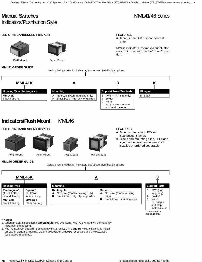
Manual Switches MML41/46 SeriesIndicators/Pushbutton Style
78 Honeywell 1 MICRO SWITCH Sensing and Control For application help: call 1-800-537-6945.
LED OR INCANDESCENT DISPLAY
PWB Mount Panel Mount
FEATURES1 Accepts one LED or incandescent
lamp
MML41indicators resemble a pushbuttonswitch with the button in the ‘‘down’’ posi-tion.
MML41 ORDER GUIDECatalog listing codes for indicator, less assembled display options
MML41K A 3 K
Housing Type (Rectangular) Mounting Support Posts/Terminals Plunger
MML41KBlack housing
A No bezel (PWB mounting only)K Black bezel, mtg. clip/long sides
3 PWB* (‘‘A’’ mtg. only)2 Solder0 None
For panel mount andstrip/matrix mount
K Black
Indicators/Flush Mount MML46LED OR INCANDESCENT DISPLAY
PWB Mount Panel Mount PWB Mount Panel Mount
FEATURES1 Accepts one or two LEDs or
incandescent lamps1 Bezels and mounting clips, LEDs and
legended lenses can be furnishedinstalled or ordered separately
MML46 ORDER GUIDECatalog listing codes for indicator, less assembled display options
MML46K A 3
Housing Type Mounting Support Posts
Rectangular*(1 or 2 LEDs orincand. lamps)
MML46KBlack housing
Square*(1 LED orincand. lamp)
MML46HBlack housing
Rectangular:A No bezel (PWB mounting only)K Black bezel, mtg. clip/long sides
Square:A No bezel (PWB mounting
only)R Black bezel, mounting clips
3 PWB (‘‘A’’mtg. only)
2 Solder**0 None
For snap-inand strip/matrix mount
** Rectangularhousings only.
* Notes:1. When an LED is specified in a rectangular MML46 listing, MICRO SWITCH will permanently
install it in the housing.2. MICRO SWITCH does not permanently install an LED in a square MML46 listing. To install
an LED in a square housing, order a MML93L or MML93G receptacle and a MML92 LED(see pages 88 and 90).
Courtesy of Steven Engineering , Inc. ! 230 Ryan Way, South San Francisco, CA 94080-6370 ! Main Office: (650) 588-9200 ! Outside Local Area: (800) 258-9200 ! www.stevenengineering.com

Manual Switches MML44 SeriesIndicators
80 Honeywell 1 MICRO SWITCH Sensing and Control For application help: call 1-800-537-6945.
LED DISPLAY
PWB Mount Panel Mount
FEATURES1 Accepts one LED only1 Bezels and mounting clips, and
legended lenses can be furnishedinstalled or ordered separately
Example: MML44KAAIndicator housing (black) which will ac-commodate one LED, no bezel
Example: MML44KA3RSDRAs above, except furnished with red LED(PWB terminals) and lens installed.
MML44 ORDER GUIDE
Catalog listing codes for indicator, less assembled display options
MML44K A 3 RS
Housing Type(Rectangular) Mounting Terminals LED
(Stanley type)
MML44KBlack housing
A No bezel (PWB mounting)K Black bezel, mtg. clip/long sidesM Black bezel, mtg. clip/short sides
A None2 Solder3 Printed wiring
board*
XX NoRS RedYS YellowGS Green
*Use only ifassembled LED isspecified.
Courtesy of Steven Engineering , Inc. ! 230 Ryan Way, South San Francisco, CA 94080-6370 ! Main Office: (650) 588-9200 ! Outside Local Area: (800) 258-9200 ! www.stevenengineering.com

Manual Switches MML44 Series
For application help: call 1-800-537-6945. Honeywell 1 MICRO SWITCH Sensing and Control 81
Bezels Page 86LEDs Page 88Lenses Page 82Strip mounting Page 85Mounting dimensions Page 92/94PWB pin locations Page 93/93
Order display options assembled toindicator by adding codes below
DRLeave this space blankif legend not desired
Lens Legend
DR RedDY YellowDG GreenDC Clear
20 With legend
Use Legend Order Sheet FO-74024 to cover eachcatalog listing.
CUSTOMERINSTALLATION:LED1. Order LED and
receptacle, page 87.2. Installation instructions,
page 88.
Manuals
Courtesy of Steven Engineering , Inc. ! 230 Ryan Way, South San Francisco, CA 94080-6370 ! Main Office: (650) 588-9200 ! Outside Local Area: (800) 258-9200 ! www.stevenengineering.com
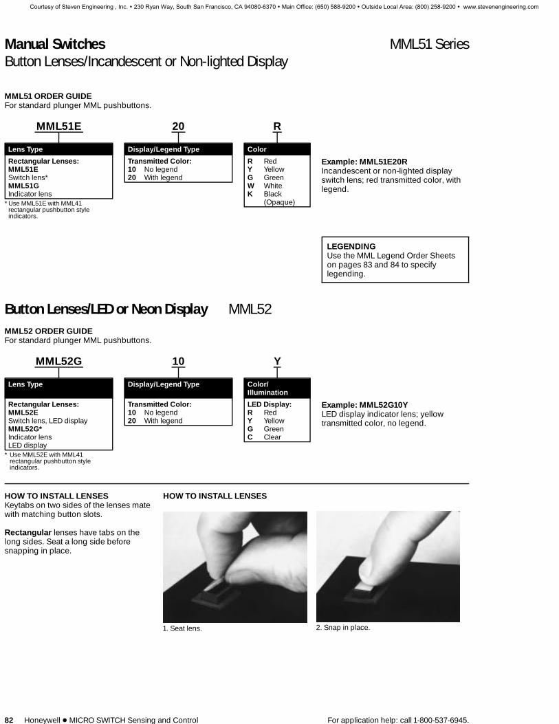
Manual Switches MML51 SeriesButton Lenses/Incandescent or Non-lighted Display
82 Honeywell 1 MICRO SWITCH Sensing and Control For application help: call 1-800-537-6945.
MML51 ORDER GUIDEFor standard plunger MML pushbuttons.
MML51E 20 R
Lens Type Display/Legend Type Color
Rectangular Lenses:MML51ESwitch lens*MML51GIndicator lens
*Use MML51E with MML41rectangular pushbutton styleindicators.
Transmitted Color:10 No legend20 With legend
R RedY YellowG GreenW WhiteK Black
(Opaque)
Example: MML51E20RIncandescent or non-lighted displayswitch lens; red transmitted color, withlegend.
LEGENDINGUse the MML Legend Order Sheetson pages 83 and 84 to specifylegending.
Button Lenses/LED or Neon Display MML52MML52 ORDER GUIDEFor standard plunger MML pushbuttons.
MML52G 10 Y
Lens Type Display/Legend Type Color/Illumination
Rectangular Lenses:MML52ESwitch lens, LED displayMML52G*Indicator lensLED display
* Use MML52E with MML41rectangular pushbutton styleindicators.
Transmitted Color:10 No legend20 With legend
LED Display:R RedY YellowG GreenC Clear
Example: MML52G10YLED display indicator lens; yellowtransmitted color, no legend.
HOW TO INSTALL LENSESKeytabs on two sides of the lenses matewith matching button slots.
Rectangular lenses have tabs on thelong sides. Seat a long side beforesnapping in place.
HOW TO INSTALL LENSES
1. Seat lens. 2. Snap in place.
Courtesy of Steven Engineering , Inc. ! 230 Ryan Way, South San Francisco, CA 94080-6370 ! Main Office: (650) 588-9200 ! Outside Local Area: (800) 258-9200 ! www.stevenengineering.com

Manual Switches MML61 SeriesStrip Mounting Frames
For application help: call 1-800-537-6945. Honeywell 1 MICRO SWITCH Sensing and Control 85
MML61 ORDER GUIDE
MML61K 5
Orientation/Color No. of Stations
For Rectangular* Housings:MML61KHorizontal strip, blackMML61GVertical strip, black
For Square HousingsMML61JBlack
* * .4N x .6N housings only.
1 One2 Two3 Three4 Four5 Five6 Six7 Seven8 Eight9 Nine
10 Ten
Note: Switches and indicators are ordered asseparate items.
FEATURES1 Provides back of panel or printed
wiring board mounting in a multi-unitstrip of switches/indicators.
1 Devices can be pre-wired prior toinstallation.
1 Holes at each end of frame will acceptNo. 4 screws.
Example: MML61K5Black 5-station strip mounting frame, hor-izontal orientation.
Refer to pages 101, 102 and 103 formounting dimensions.
Manuals
Courtesy of Steven Engineering , Inc. ! 230 Ryan Way, South San Francisco, CA 94080-6370 ! Main Office: (650) 588-9200 ! Outside Local Area: (800) 258-9200 ! www.stevenengineering.com

Manual Switches MML72 SeriesBezels/Mounting Clips
86 Honeywell 1 MICRO SWITCH Sensing and Control For application help: call 1-800-537-6945.
1. Slip mounting clip over top of switch/indicator housing.
2. Snap bezel onto mounting clip.
Recommended panel thickness forpanel mounted units is .050 to .094 in.(1,27 to 2,39 mm).
MML72 ORDER GUIDE(Incl. bezel & mounting clips)
MML72EE K
Type Color
For Rectangular* Housings:MML72EE*Switch: Mtg. clips on long sides
* Use this type with MML41 rectangular pushbuttonstyle indicators.
K Black
Example: MML72EEKBlack switch bezel, mounting clips onlong sides.
TO ORDER MOUNTING CLIPSSEPARATELY
For Rectangular Housings:MML73EA (long sides)MML73EB (short sides)
For Square Housings:MML73BA
PWB Mount Support Bracket MML74 SeriesThese metal frames with PWB supportterminals provide added rigidity for stand-alone PWB mounted switches and indica-tors. They are not for use with MML57 but-tons.
See page 98 for mounting dimensions.
MML74 ORDER GUIDE
CatalogListing For Use With:
MML74E Rectangular .4N x .6N housings
MML74B Square housings
Courtesy of Steven Engineering , Inc. ! 230 Ryan Way, South San Francisco, CA 94080-6370 ! Main Office: (650) 588-9200 ! Outside Local Area: (800) 258-9200 ! www.stevenengineering.com
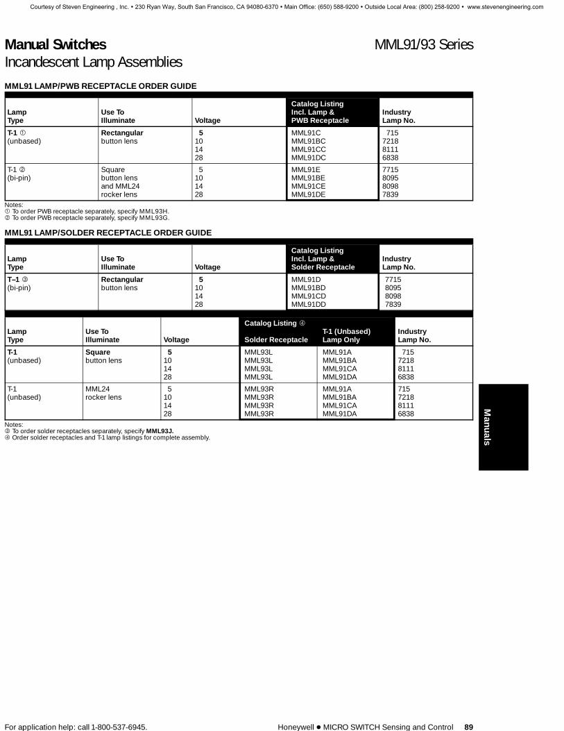
Manual Switches MML91/93 SeriesIncandescent Lamp Assemblies
For application help: call 1-800-537-6945. Honeywell 1 MICRO SWITCH Sensing and Control 89
MML91 LAMP/PWB RECEPTACLE ORDER GUIDE
Catalog ListingLamp Use To Incl. Lamp & IndustryType Illuminate Voltage PWB Receptacle Lamp No.
T-1 1 Rectangular 5 MML91C 715(unbased) button lens 10 MML91BC 7218
14 MML91CC 811128 MML91DC 6838
T-1 2 Square 5 MML91E 7715(bi-pin) button lens 10 MML91BE 8095
and MML24 14 MML91CE 8098rocker lens 28 MML91DE 7839
Notes:1 To order PWB receptacle separately, specify MML93H.2 To order PWB receptacle separately, specify MML93G.
MML91 LAMP/SOLDER RECEPTACLE ORDER GUIDE
Catalog ListingLamp Use To Incl. Lamp & IndustryType Illuminate Voltage Solder Receptacle Lamp No.
T–1 3 Rectangular 5 MML91D 7715(bi-pin) button lens 10 MML91BD 8095
14 MML91CD 809828 MML91DD 7839
Catalog Listing 4
Lamp Use To T-1 (Unbased) IndustryType Illuminate Voltage Solder Receptacle Lamp Only Lamp No.
T-1 Square 5 MML93L MML91A 715(unbased) button lens 10 MML93L MML91BA 7218
14 MML93L MML91CA 811128 MML93L MML91DA 6838
T-1 MML24 5 MML93R MML91A 715(unbased) rocker lens 10 MML93R MML91BA 7218
14 MML93R MML91CA 811128 MML93R MML91DA 6838
Notes:3 To order solder receptacles separately, specify MML93J.4 Order solder receptacles and T-1 lamp listings for complete assembly.
Manuals
Courtesy of Steven Engineering , Inc. ! 230 Ryan Way, South San Francisco, CA 94080-6370 ! Main Office: (650) 588-9200 ! Outside Local Area: (800) 258-9200 ! www.stevenengineering.com

Manual Switches MML93 SeriesLED/Incandescent Lamp Receptacles
90 Honeywell 1 MICRO SWITCH Sensing and Control For application help: call 1-800-537-6945.
User installed. Certain MML switchesand indicators will accept incandescentlamps, where specified in the orderguides.
These lamps are ordered separately andinstalled by the user, per the proceduresdescribed below.
LAMP INSTALLATION
1. With Printed Wiring BoardReceptacle for MML93G andMML93H only.Use PWB receptacles to permitlamps to be added or replaced frombehind the printed wiring board,without soldering.
These receptacles are for use withrectangular pushbuttons, squarepushbuttons and MML24 rocker lensonly.
Printed wiring boards are notsupplied.
1. Insert the PWB receptacle/incandescent lamp assemblythrough a hole in the printed wiringboard.
2. A 1⁄8–turn applied clockwise to thereceptacle locks it in the printedwiring board and establishes theelectrical connection.
2. With Solder Terminal Receptaclefor MML93J bi-pin onlyThis receptacle attaches directly tothe rear of panel-mounted units. Itenables lamps to be added orreplaced without rewiring.
This receptacle is for use with allrectangular pushbuttons and MML41or MML46 rectangular indicatorsonly.
1. Insert solder terminal receptacle intohole in base of panel mount unit.
2. A 1⁄8–turn clockwise applied to thereceptacle locks it in the base.
3. With Solder Terminal Receptaclesfor MML93L/93R Unbased Only orT-1 LED.Use the receptacles shown at right toinstall T–1 LEDs or T–1 unbased lampsin panel-mounted MML21 squarepushbutton switches and MML24rocker switches.
Procedure:1. Assemble LEDs or lamps to
receptacles (leads first).2. Snap receptacle into slots in housing
base.3. Solder directly to leads.
Courtesy of Steven Engineering , Inc. ! 230 Ryan Way, South San Francisco, CA 94080-6370 ! Main Office: (650) 588-9200 ! Outside Local Area: (800) 258-9200 ! www.stevenengineering.com

Manual Switches MML92 SeriesLEDs
88 Honeywell 1 MICRO SWITCH Sensing and Control For application help: call 1-800-537-6945.
Factory installed. Certain MML switchesand indicators can be furnished withLEDs permanently factory installed,where specified in the order guides.
User installed. LEDs can also be orderedseparately and installed in these productsby the user, per the procedures de-scribed below.
LED INSTALLATION
1. With Printed Wiring BoardReceptacle. (MML93K)PWB receptacle enables T-1 3⁄4 or T-1LEDs to be added or replaced from be-hind the printed wiring board, withoutsoldering. LEDs and receptacles areordered separately. See page 87.
Printed wiring boards are not supplied. 1. Insert the LED/PWB receptacle as-sembly through a hole in the printedwiring board.
2. A 1⁄8–turn applied clockwise to the re-ceptacle locks it in the printed wiringboard and establishes the electricalconnection.
2. With Solder Terminal Receptacle.(MML93J)This receptacle attaches directly to therear of panel-mounted units. It enablesincandescent lamps to be added or re-placed without rewiring. LEDs and re-ceptacles are ordered separately.
This receptacle is for use with all rect-angular pushbuttons and MML41 orMML46 rectangular indicators only. 1. Insert solder terminal receptacle into
hole in base of panel mount unit.2. A 1⁄8–turn clockwise applied to the re-
ceptacle locks it in the base.
3. By Soldering To Printed WiringBoard.In this procedure, the housing ismounted on the printed wiring boardafter the T-1 3⁄4 LED has been seated.
This procedure can be used with anyMML having PWB terminals.
1. Assemble stand-off spacer to LED ter-minals and seat on printed wiringboard.
2. Seat housing on printed wiring board,with LED projecting into hole at thebase of the housing.
4. By Soldering to Printed Wiring Boardor Leadwire (MML44 indicatorsonly).T-1 3⁄4 LEDs are added to MML44 indi-cators via a procedure which is uniqueto this product. The LED is insertedfrom the top of the housing with theleadwires protruding through thehousing base.
1. Assemble LED to MML44 indicator,with the LED terminals protrudingthrough assembly slot in the middle ofhousing base.
2. Use pencil eraser to snap LED securelyin place.
Courtesy of Steven Engineering , Inc. ! 230 Ryan Way, South San Francisco, CA 94080-6370 ! Main Office: (650) 588-9200 ! Outside Local Area: (800) 258-9200 ! www.stevenengineering.com

Manual Switches MML92/93 SeriesLEDs
For application help: call 1-800-537-6945. Honeywell 1 MICRO SWITCH Sensing and Control 87
LED APPLICATION INFORMATION
To insure stable conditions, suitable ex-ternal control of the LED current must beprovided. It is recommended that a mini-mum of 5 VDC open circuit voltage withan appropriate series resistance be usedto drive LED devices. This minimizes cur-rent variation and its effect on temper-ature and forward voltage of the LED.
Maximum drive current is 30 mA. Reversevoltage breakdown of the LED’s is 4 volts(min.).
Resistor values can be determined bysupply voltage or current for LED:
RS =E – Vf
If
WHERE: RS = Series ResistanceE = Supply VoltageVf = Forward Voltage
of LEDIf = Circuit Current
MML92 ORDER GUIDELEDs should be the same color as the lenses they illuminate. They are packed 10 per listing, including stand-off spacers for usewhen solder terminating to a printed wiring board, per procedure 3 on page 88.
Forward LEDLED Use To Catalog LED Characteristics Manufacturers’Type Illuminate Listing Color Typ. @ 20mA Max. Part Numbers
Stanley:T–13⁄4 Rectangularbutton lens MML92ERS
MML92EGSMML92EYS
RedGreenYellow
1.7 V2.1 V2.1 V
2.0 V2.5 V2.5 V
ESBR5633ESBG5633ESAY5633
Hewlett Packard:MML92ERHMML92EGHMML92EYH
RedGreenYellow
2.2 V2.3 V2.2 V
3.0 V3.0 V3.0 V
HLMP-3366HLMP-3568HLMP-3466
Stanley:T–1 Square buttonlens, MML24rocker lensrectangularbutton lens
MML92HRSMML92HGSMML92HYS
RedGreenYellow
1.7 V2.1 V2.2 V
2.0 V2.5 V2.5 V
ESBR3901ESPY3901ESAY3901
Hewlett Packard:MML92HRHMML92HGHMML92HYH
RedGreenYellow
2.2 V*2.3 V*2.2 V
3.0 V3.0 V3.0 V
HLMP-1340HLMP-1540HLMP-1440
Long lead: Anode (+). Short lead: Cathode (−).* @ 25 mA.
MML93 LED PWB RECEPTACLE ORDER GUIDE
LEDType Use to Illuminate
CatalogListing
T-13⁄4 Rectangular button lens or umbrella buttonlens MML93K
T-1 Square button lens or MML24 rocker lens MML93G
MML93 LED SOLDER TERMINAL ORDER GUIDE
LEDType Use to Illuminate
CatalogListing
T-1 Square button MML93L
T-1 MML24 rocker lens MML93R
T-1 Rectangular button MML93J
Manuals
Courtesy of Steven Engineering , Inc. ! 230 Ryan Way, South San Francisco, CA 94080-6370 ! Main Office: (650) 588-9200 ! Outside Local Area: (800) 258-9200 ! www.stevenengineering.com

Manual Switches MML91/93 SeriesIncandescent Lamp Assemblies
For application help: call 1-800-537-6945. Honeywell 1 MICRO SWITCH Sensing and Control 89
MML91 LAMP/PWB RECEPTACLE ORDER GUIDE
Catalog ListingLamp Use To Incl. Lamp & IndustryType Illuminate Voltage PWB Receptacle Lamp No.
T-1 1 Rectangular 5 MML91C 715(unbased) button lens 10 MML91BC 7218
14 MML91CC 811128 MML91DC 6838
T-1 2 Square 5 MML91E 7715(bi-pin) button lens 10 MML91BE 8095
and MML24 14 MML91CE 8098rocker lens 28 MML91DE 7839
Notes:1 To order PWB receptacle separately, specify MML93H.2 To order PWB receptacle separately, specify MML93G.
MML91 LAMP/SOLDER RECEPTACLE ORDER GUIDE
Catalog ListingLamp Use To Incl. Lamp & IndustryType Illuminate Voltage Solder Receptacle Lamp No.
T–1 3 Rectangular 5 MML91D 7715(bi-pin) button lens 10 MML91BD 8095
14 MML91CD 809828 MML91DD 7839
Catalog Listing 4
Lamp Use To T-1 (Unbased) IndustryType Illuminate Voltage Solder Receptacle Lamp Only Lamp No.
T-1 Square 5 MML93L MML91A 715(unbased) button lens 10 MML93L MML91BA 7218
14 MML93L MML91CA 811128 MML93L MML91DA 6838
T-1 MML24 5 MML93R MML91A 715(unbased) rocker lens 10 MML93R MML91BA 7218
14 MML93R MML91CA 811128 MML93R MML91DA 6838
Notes:3 To order solder receptacles separately, specify MML93J.4 Order solder receptacles and T-1 lamp listings for complete assembly.
Manuals
Courtesy of Steven Engineering , Inc. ! 230 Ryan Way, South San Francisco, CA 94080-6370 ! Main Office: (650) 588-9200 ! Outside Local Area: (800) 258-9200 ! www.stevenengineering.com

Manual Switches MML93 SeriesLED/Incandescent Lamp Receptacles
90 Honeywell 1 MICRO SWITCH Sensing and Control For application help: call 1-800-537-6945.
User installed. Certain MML switchesand indicators will accept incandescentlamps, where specified in the orderguides.
These lamps are ordered separately andinstalled by the user, per the proceduresdescribed below.
LAMP INSTALLATION
1. With Printed Wiring BoardReceptacle for MML93G andMML93H only.Use PWB receptacles to permitlamps to be added or replaced frombehind the printed wiring board,without soldering.
These receptacles are for use withrectangular pushbuttons, squarepushbuttons and MML24 rocker lensonly.
Printed wiring boards are notsupplied.
1. Insert the PWB receptacle/incandescent lamp assemblythrough a hole in the printed wiringboard.
2. A 1⁄8–turn applied clockwise to thereceptacle locks it in the printedwiring board and establishes theelectrical connection.
2. With Solder Terminal Receptaclefor MML93J bi-pin onlyThis receptacle attaches directly tothe rear of panel-mounted units. Itenables lamps to be added orreplaced without rewiring.
This receptacle is for use with allrectangular pushbuttons and MML41or MML46 rectangular indicatorsonly.
1. Insert solder terminal receptacle intohole in base of panel mount unit.
2. A 1⁄8–turn clockwise applied to thereceptacle locks it in the base.
3. With Solder Terminal Receptaclesfor MML93L/93R Unbased Only orT-1 LED.Use the receptacles shown at right toinstall T–1 LEDs or T–1 unbased lampsin panel-mounted MML21 squarepushbutton switches and MML24rocker switches.
Procedure:1. Assemble LEDs or lamps to
receptacles (leads first).2. Snap receptacle into slots in housing
base.3. Solder directly to leads.
Courtesy of Steven Engineering , Inc. ! 230 Ryan Way, South San Francisco, CA 94080-6370 ! Main Office: (650) 588-9200 ! Outside Local Area: (800) 258-9200 ! www.stevenengineering.com

Multi-Light Oiltight Controls CMC Series
For application help: call 1-800-537-6945. Honeywell 1 MICRO SWITCH Sensing and Control 3
INDICATOR PUSHBUTTON
SELECTORSELECTOR-PUSH2-3-4 POSITION
2-3-4 POSITION
MULTI-LIGHT OILTIGHT CONTROLS
CMC square, multi-light controls are ideal for process controlpanels. They are available with selector, pushbutton, and select-or-push actuators, and mechanical or electronic duty contactblocks.
1 Indicators, pushbuttons, selectors, and selector-push units1 Mechanical and electronic duty contact blocks1 Contact blocks tandem mount behind operator1 More circuitry control than with any other control by using
four plunger adapter kit1 Legend plates with legending in square or diagonal formats1 Bright, lighted displays with good contrast for easy
identification1 Square shape is compatible with other panel controls1 Rotary cam-actuated contact blocks1 NEMA 13, oiltight and dusttight1 CSA certified no. LR573261 UL listed file no. E37138
TABLE OF CONTENTSCMC Multi-light Oiltight Controls
Contact blocks . . . . . . . . . . . . . . . . . . . . . . . . . . . . . . . . . . . . . 4Four plunger adapter kit . . . . . . . . . . . . . . . . . . . . . . . . . . . . . 5Ordering guidelines . . . . . . . . . . . . . . . . . . . . . . . . . . . . . . . . . 6Terminal construction for lamp operation . . . . . . . . . . . . . . . 6Indicators and pushbuttons . . . . . . . . . . . . . . . . . . . . . . . . . . 7910 and 913 selectors . . . . . . . . . . . . . . . . . . . . . . . . . . . . . . . 8911 and 914 selector-push units . . . . . . . . . . . . . . . . . . . . . . 10Cover plates, color inserts, and legend plates . . . . . . . . . 12Legend plates . . . . . . . . . . . . . . . . . . . . . . . . . . . . . . . . . . . . . 16Typical CMC applications . . . . . . . . . . . . . . . . . . . . . . . . . . . 18Specification sheet . . . . . . . . . . . . . . . . . . . . . . . . . . . . . . . . . 20Legend order sheet . . . . . . . . . . . . . . . . . . . . . . . . . . . . . . . . 22Accessories . . . . . . . . . . . . . . . . . . . . . . . . . . . . . . . . . . . . . . . 23Replacement parts . . . . . . . . . . . . . . . . . . . . . . . . . . . . . . . . . 24Mounting dimensions . . . . . . . . . . . . . . . . . . . . . . . . . . . . . . 25920/921 rotary cam-actuated contact blocks . . . . . . . . 26Typical applications . . . . . . . . . . . . . . . . . . . . . . . . . . . . . . . . 27Ordering information . . . . . . . . . . . . . . . . . . . . . . . . . . . . . . . 28
Other MICRO SWITCH Solutions . . . . . . . . . . . . . . . . . . . . . 30
Courtesy of Steven Engineering , Inc. ! 230 Ryan Way, South San Francisco, CA 94080-6370 ! Main Office: (650) 588-9200 ! Outside Local Area: (800) 258-9200 ! www.stevenengineering.com
TED RUDOLPH
SOLD TO SENASYS LLC 888-736-2797

Multi-Light Oiltight Controls CMC SeriesIndicators and Pushbuttons
For application help: call 1-800-537-6945. Honeywell 1 MICRO SWITCH Sensing and Control 7
1 Suitable for use in NEMA 13enclosures.
Indicator1 Four lighted quadrants1 Two or four transformers, 120 or 240
VAC1 Jumpers available for low voltage
applications.1 Resistor boards available for 24V or
48V supply
1 Each lamp individually controlled1 Cover plates, color inserts, and
legend plates are ordered separately.
Pushbutton1 Actuate up to four 2-plunger contact
blocks in any combination1 Lighted and unlighted versions
available
1 Two or four transformers, 120 or 240VAC
1 Jumpers available for low voltageapplications
1 Resistor boards available for 24V or48V supply
1 Each lamp individually controlled.1 Cover plates, color inserts, and
legend plates are ordered separately
INDICATOR CATALOG LISTING PUSHBUTTON CATALOG LISTING
908AAA-- 909AAA--Gray Button
909BAA--Black Button
ORDER GUIDEComplete the last two blanks of the cata-log listing with the terminal number,which is colored in the table at the right.
Order incandescent cover plate, color in-serts, and legend plate separately frompage 12.
Order LED lamps and color inserts sep-arately.
6VAC/DC - Page 1424VAC/DC - Page 15
Contact blocks may be ordered separate-ly from page 4.
QUADRANT AREAS
908AAA--, 909AAA--, 909BAA--
67 —Unlighted
FOUR TERMINAL UNITS use with 2 lamps
95 —120 VAC transformers (2) and No. 755 lamps in quadrants A & B, nothing in quads C & D96 —120 VAC transformers (2) and No. 755 lamps in quadrants C & D, nothing in quads A & B97 —Line voltage jumpers in quadrants A & B, no lamps, nothing in quads C & D. Can be
used with incandescent or LED bulbs.98 —Line voltage jumpers in quadrants C & D, no lamps, nothing in quads A & B. Can be
used with incandescent or LED bulbs.38 —120 VAC transformers (2) in quadrants A & B. Quadrants C & D unlighted. For use with 6
volt LED lamps and color inserts. Order from page 14.
FIVE TERMINAL UNITS use with 4 lamps
01 —120 VAC transformers (4) and (4) No. 755 lamps02 —240 VAC transformers (4) and (4) No. 755 lamps03 —Line voltage jumpers (4)—Less lamps1. Can be used with incandescent or LED bulbs.40 —48 volt resistors (4) and (4) No. 1819 lamps05 —24 volt resistors (4) and (4) No. 756 lamps15 —120 VAC transformers (4). For use with 6 volt LED lamps and color inserts. Order from
page 14.16 —240 VAC transformers (4). For use with 6 volt LED lamps and color inserts. Order from
page 14.
EIGHT TERMINAL UNITS use with 4 lamps
51 —120 VAC transformers (4) and (4) No. 755 lamps52 —240 VAC transformers (4) and (4) No. 755 lamps53 —Line voltage jumpers (4) less lamps1. Can be used with incandescent or LED bulbs.90 —48 volt resistors (4) and (4) No. 1819 lamps50 —24 volt resistors (4) and (4) No. 756 lamps55 —120 VAC transformers (4). For use with 6 volt LED lamps and color inserts. Order from
page 14.56 —240 VAC transformers (4). For use with 6 volt LED lamps and color inserts. Order from
page 14.1 See Page 23 for 2-28 volt lamp recommendations.Contact MICRO SWITCH Branch Office for combinations of lamp voltages in one unit.
Courtesy of Steven Engineering , Inc. ! 230 Ryan Way, South San Francisco, CA 94080-6370 ! Main Office: (650) 588-9200 ! Outside Local Area: (800) 258-9200 ! www.stevenengineering.com

Multi-Light Oiltight Controls CMC SeriesFour Plunger Adapter Kit
For application help: call 1-800-537-6945. Honeywell 1 MICRO SWITCH Sensing and Control 5
1 Exclusive four plunger actuation for se-lector and selector-push units.
1 Affords more circuit sequencing possi-bilities by using all four points on thecam.
1 Any combination of heavy duty andelectronic duty contact blocks (up tofour) may be used per operator.
Catalog ListingPTCA
CIRCUIT SEQUENCING CONTROLCOMPARISON
2 PLUNGER ACTUATION
TURNCAM
BLOCK 1
BLOCK 2
BLOCK 3
BLOCK 4
4 PLUNGER ACTUATION
BETWEEN BLOCKS 1 & 2
TURNCAM
BLOCK 1
4 PLUNGERADAPTER
BLOCK 2
BLOCK 3
BLOCK 4
* 4 Plunger Adapter Kit (Catalog Listing PTCA) in-cludes two sets of auxiliary and offset plungers. Oneset is .200 inch longer than the other set in order tomatch the variation in 2-circuit and 4-circuit blockdepth.
Courtesy of Steven Engineering , Inc. ! 230 Ryan Way, South San Francisco, CA 94080-6370 ! Main Office: (650) 588-9200 ! Outside Local Area: (800) 258-9200 ! www.stevenengineering.com

Multi-Light Oiltight Controls CMC SeriesRotary Contact Blocks
26 Honeywell 1 MICRO SWITCH Sensing and Control For application help: call 1-800-537-6945.
ELECTRICAL INTERRUPTINGRATINGS (amperes)The electrical ratings are 600 VAC, 250VDC and 20 amperes continuous carry or180 amperes for three seconds.
920/921 CMC ROTARY CAM-ACTUATED CONTACT BLOCKS1 Up to 12 positions available1 Controls up to 24 circuits1 Positive detent between positions1 Mechanical memory stages
The 920/921CMC series are highly versa-tile rotary cam-actuated contact blocksavailable with CMC selectors. These con-tact blocks are ideal for applications re-quiring a large number of contacts actuat-ed simultaneously by one device. Theyare designed for control circuits in appli-cations such as instrumentation andpower generation.
MECHANICAL MEMORYA special cam and slip clutch (M210) canbe specified to provide mechanical mem-ory.
Drawing A
Drawing B
Drawing A represents a three position se-lector with spring return from both direc-tions. Circuits 7 and 8 - contacts, 13-14and15-16 are the slip (mechanical memo-ry) contacts. M210 is the slip clutch. Draw-ing B is a simplified explanation of howmechanical memory works.
1. In the center position step 1, contacts13-14 and 15-16 are open. The switch(drawing A) is in the normal after TRIPposition.
2. Step 2 shows the contact closures asthe knob is rotated clockwise to theCLOSE position, (13-14 and 15-16close).
3. Step 3 illustrates that the contacts re-main closed after the selector knobspring-returns to the center position.
4. In step 4, the knob is rotated counter-clockwise to the TRIP position, open-ing contacts 13-14 and 15-16.
5. This state is maintained after the knobspring-returns to center, step 5.
Courtesy of Steven Engineering , Inc. ! 230 Ryan Way, South San Francisco, CA 94080-6370 ! Main Office: (650) 588-9200 ! Outside Local Area: (800) 258-9200 ! www.stevenengineering.com

Multi-Light Oiltight Controls CMC SeriesRotary Contact Blocks
For application help: call 1-800-537-6945. Honeywell 1 MICRO SWITCH Sensing and Control 27
TYPICAL APPLICATION 920 CMC (LOCKOUT)
Circuit BreakerControl Switchwith Lockout
For identification ONLYDo not build catalog listings from this information. Seenext page for ordering information.
Number Degrees Start Switchingof Between Selector Position StagePositions Position Action Lamp Service Orientation Type
Selector920
A Two Position A 30° A Maintained 01 A 0° Four Digit NumberB Three Position B 45° 02 B 30° Assigned by FreeportC Four Position C 60° B CW Spring Return 05 C 45°D Five Position D 90° C CCW Spring Return 40 D 60°E Six Position E Various D CW & CCW Spring Return 50 E 90°F Seven Position E CW & CCW Spring Return and Lockout 51 F 120°G Eight Position F CW Spring Return and Lockout 52 G 135°H Nine Position 90 H 150°J Ten Position J 180°K Eleven Position 03 K 210°L Twelve Position 53 L 225°
M 240°67 N 270°
P 300°95 R 315°96 S 330°
T 345°97 U 285°98
Selector-Push921
Courtesy of Steven Engineering , Inc. ! 230 Ryan Way, South San Francisco, CA 94080-6370 ! Main Office: (650) 588-9200 ! Outside Local Area: (800) 258-9200 ! www.stevenengineering.com

Multi-Light Oiltight Controls CMC SeriesSelector - Push Units
10 Honeywell 1 MICRO SWITCH Sensing and Control For application help: call 1-800-537-6945.
V V
CMC SELECTORS1 Suitable for use in NEMA 13 enclosures.1 Accepts 4 plunger adapter kit
Example:911 A G
Operator
911 —Grey knob914 —Black knob
Turn CamConfiguration
Insert the turn cam comfiguration codefrom the shaded area of the chart below.
1. Match your circuit requirements in onecam code column in the chart below.*
2. Develop the catalog listing of the unit,including the shaded letters of the camcode configuration selected in step 1from the chart below.
3. Consider position number1as the fur-thest counter-clockwise device position.Order contact block(s) and adapter kit asindicated in the left hand column of thecam code selection chart.
Selector Action
2 Position 3 Position 4 Position
A – Pos. 1, 2E – Pos. 2, 3H – Pos. 3, 4L – Pos. 4, 1
U – Pos. 9, 12o’clock
V – Pos. 12, 3o’clock
W – Pos. 3, 6o’clock
X – Pos. 6, 9o’clock
B – Pos. 1, 2, 3F – Pos. 2, 3, 4J – Pos. 3, 4, 1M – Pos. 4, 1, 2
P – Pos. 9, 12,3 o’clock
R – Pos. 12, 3,6 o’clock
S – Pos. 3, 6,9 o’clock
T – Pos. 6, 9,12 o’clock
C – Pos. 1, 2, 3, 4no stop
D – Pos. 1, 2, 3, 4stop between1 and 4
G – Pos. 2, 3, 4, 1stop between2 and 1
K – Pos. 3, 4, 1, 2stop between3 and 2
N – Pos. 4, 1, 2, 3stop between3 and 4
Y – Pos. 9, 12, 3, 6o’clock. No.stop.
Z – Pos. 9, 12, 3, 6o’clock. Stopbetween 6 and9
CAM CODE SELECTION CHART *‘‘X’’ — Circuit Closure‘‘O’’ — Circuit Open
Number of Positions: 2-Positions 3-Positions 4-PositionsTurn Cam: Configuration: B J G G G R L K G A R L
Orientation: 3 1 1 3 1 1 1 4 1 1 1 1Push Cam Code: YA TC BB FB TB FB MA ED MC MD BC VBDevice Positions: 1 2 1 2 1 2 1 2 1 2 1 2 1 2 3 1 2 3 1 2 3 1 2 3 1 2 3 4 1 2 3 4Contact1,2
block Terminal Condition
PTCC 1-2 Free O X X O O X X X O X X X X O O X X O O X X X O O X X X X X O O ODepress O O O O O X X O O X O X X O O X X O O O X O O O O X X X O O O O
3-4 Free O O O O X O O O X O O O O O O O O O X O O O O X O O O O O O O ODepress X X X X X O O X X O X O O O X O O X X O O O X X X O O O X O O O
5-6 Free X O X O X X O X X X X X O O X O O X X X O O X X X X X X O O X ODepress O O X O X O O X O O X O O O X O O X X O O O X O X X O X O O O O
7-8 Free O X O O O O X O O O O O O O O O O O O O X X O O O O O O O O O ODepress O X O X O X X O X X O X X O O X O O O O X X O O O O X O O O X O
4-Plunger Adapter Kit3
PTCA For circuits below — Use 4 plunger adapter kit and at least 1 block from above
PTCC 1-2 Free — O X X O — X O X X O X O O X X X O X X X O X X X X O X O ODepress — O O O O — O O O O O X O O X X O O O X O O X O X X O O O O
3-4 Free X O O O O X — O X O O — — O X O O O O O O O O O O O ODepress X X X X X X — X X X X — — O X O O O X O X O O O X O O
5-6 Free X X O X — X O X X — — X O O X X X O O X X X X X O O O XDepress O O O X — O O X O — — X O O O X O O O X X X X O O O O O
7-8 Free O O O O — O X O O — O O O O O O — O X O O O O O O O O ODepress X O X O — X X O X — O X O O X O — X X O O O O X O O O X
Notes:1 Order contact blocks separately from page 4.
Only PTCC contact blocks are charted. Allother contact block alternatives may be sub-stituted for portions of PTCC circuitry.
2 Contact block PTCB, with its location arrowaligned with the operator, provides the circui-try equivalent to 1-2 and 7-8 of the PTCCblock. When PTCB is reversed (turned 180°),so location arrows do not align with operator,the circuitry obtained is equivalent to 3-4 and5-6 of the PTCC block. PTCD with arrowsaligned, provides same circuit as 7-8 of PTCCblock.
When reversed (arrows not aligned), the cir-cuit obtained is equivalent to 3-4 of PTCCblock. PTCE with arrows aligned, providessame circuit as 1-2 of PTCC block. When re-versed (arrows not aligned), the circuit ob-tained is equivalent to 5-6 of PTCC block.
3 PTCA is explained on page 5.4 Use up to 4 contact blocks with maintained
forms and up to 2 with spring return forms.
Courtesy of Steven Engineering , Inc. ! 230 Ryan Way, South San Francisco, CA 94080-6370 ! Main Office: (650) 588-9200 ! Outside Local Area: (800) 258-9200 ! www.stevenengineering.com

Multi-Light Oiltight Controls CMC SeriesSelector-Push Units
For application help: call 1-800-537-6945. Honeywell 1 MICRO SWITCH Sensing and Control 11
COVER PLATE LEGEND OPERATOR BLOCKSINSERTS PLATEF F F J
COMPLETEUNIT
A
OperatorFunction
A –MaintainedB –Clockwise
spring returnfrom left (2 and3 pos)
C–Counterclock-wise springreturn from right(2 and 3 pos)
D–Clockwise andcounterclock-wise springreturn to centerfrom left andright (3 pos)
F –Uni-rotationalclockwise (4pos. only, nostop)
01
Lamp Terminalsand Service
67 –Unlighted 5 Term. 8 Term.4 Terminal 01 51
95 –(2) 120 V transformersand (2) No. 755 lamps inquadrants A & B only.
96 –(2) 120 V transformersand (2) No. 755 lamps inquadrants C & D only.
97 –(2) line voltage jumpersin quadrants A & B. Nolamps.
98 –(2) line voltage jumpersin quadrants C & D. Nolamps.
Line voltage jumper versionscan use incandescent or LEDlamps.
(4) 120 V trans.and(4) No. 755lamps
02 52(4) 240 V trans.and(4) No. 755lamps
05 50(4) 24 Vresistors. (4)No. 756 lamps
40 90(4) 48 Vresistors. (4)No. 1819 lamps
03 53(4) line voltagejumpers. Nolamps.
LED Lamp Terminalsand Service
4 Terminal 5 Term. 8 Term.38 –(2) 120 V transformers in
quadrants A & B97 –(2) line voltage jumpers
in quadrants A & B. NoLED.
98 –(2) line voltage jumpersin quadrants C & D. NoLED.
Order LEDs, color inserts andcovers from pages 14-15.
15 55(4) 120V transf.
16 56(4) 240 V transf.
03 53(4) line voltagejumpers. NoLED.
1
TurnCamOrientation
Insert the camorientation code fromthe shaded area of thechart on the facingpage.
BB
Push Cam CodeInsert the push camcode from the shadedarea of the chart on thefacing page.
X
Order cover plates, colorinserts, and legendplates separately frompage 12.
*This chart lists only a few of the unlimited numberof the switch versions available. Contact yournearest MICRO SWITCH Branch Office or Autho-rized Distributor for those not shown.
Definition:Spring return is the direction the knob is turned bythe internal spring force when the operator releas-es the knob. For example, on a two position clock-wise spring return device, the knob is turned fromposition 2 to position 1 by the operator. When theoperator releases the knob, it spring returns to po-sition 2 in a clockwise direction.
DEVICE POSITIONS
QUADRANT AREAS
V V V
Courtesy of Steven Engineering , Inc. ! 230 Ryan Way, South San Francisco, CA 94080-6370 ! Main Office: (650) 588-9200 ! Outside Local Area: (800) 258-9200 ! www.stevenengineering.com

Multi-Light Oiltight Controls CMC SeriesSelector Units
8 Honeywell 1 MICRO SWITCH Sensing and Control For application help: call 1-800-537-6945.
V V
CMC SELECTORS1 Suitable for use in NEMA 13 enclosures.1 Accepts 4 plunger adapter kit
Example:910 A E
Operator
910 —Grey knob913 —Black knob
Cam
Insert cam code from chart below.
1. Match your circuit requirements in onecam code column in the chart below.*
2. Develop the catalog listing of the unit,including the shaded letters of the camcode configuration selected in step 1from the chart below.
3. Consider position number1as the fur-thest counter-clockwise device position.Order contact block(s) and adapter kit asindicated in the left hand column of thecam code selection chart.
Selector Action
2 Positions 3 Positions 4 Positions
A —Pos. 1, 2E —Pos. 2, 3H —Pos. 3, 4L —Pos. 4, 1
U —Pos. 9, 12o’clock
V —Pos. 12, 3o’clock
W —Pos. 3, 6o’clock
X —Pos. 6, 9o’clock
B —Pos. 1, 2, 3F —Pos. 2, 3, 4J —Pos. 3, 4, 1M —Pos. 4, 1, 2
P —Pos. 9, 12,3 o’clock
R —Pos. 12, 3,6 o’clock
S —Pos. 3, 6,9 o’clock
T —Pos. 6, 9,12 o’clock
C —Pos. 1, 2, 3, 4no stop
D —Pos. 1, 2, 3, 4stop between1 and 4
G —Pos. 2, 3, 4, 1stop between2 and 1
K —Pos. 3, 4, 1, 2stop between3 and 2
N —Pos. 4, 1, 2, 3stop between3 and 4
Y —Pos. 9, 12, 3, 6o’clock. No.stop.
Z —Pos. 9, 12, 3, 6o’clock. Stopbetween 6 and9
CAM CODE SELECTION CHART *‘‘X’’ — Circuit Closure‘‘O’’ — Circuit Open
2-Pos. 3-Position 4-Position
Cam: E E5 D G F H H A F G
Turn Cam: Orientation: 1 2 1 3 1 4 1 2 2 1
Device Positions: 1 2 1 2 1 2 3 1 2 3 1 2 3 1 2 3 1 2 3 4 1 2 3 4 1 2 3 4 1 2 3 4Contact1
Block Terminals
PTCC 1-2 (NC) X O O X X O O X X O O X O O X O X O O O O O X X X O X O O X X X3-4 (NO) O X X O O O X O O X X O O O O X O X O O O X O O O O O X X O O O5-6 (NC) X O O X O O X O X X O X O O O O O O X O X X O O X O X O X X O X7-8 (NO) O X X O X O O X O O O O X X O O O O O X O O O X O X O O O O X O
PTCB
1-2 (NC) X O O X X O O X X O O X O O X O X O O O O O X X X O X O O X X X3-4 (NO) O X X O X O O X O O O O X X O O O O O X O O O X O X O O O O X O
Rev. PTCB
3-4 (NO) O X X O O O X O O X X O O O O X O X O O O X O O O O O X X O O O1-2 (NC) X O O X O O X O X X O X O O O O O O X O X X O O X O X O X X O X
4-PlungerAdapter Kit PTCA2 For circuits below — Use 4 plunger adapter kit and at least 1 block from above
PTCC 1-2 (NC) O X O X X X X O X X O O X O X O X X O X X3-4 (NO) O O O O O O O X O O O X O X O O O O X O O5-6 (NC) O O O X O X X O X O X X O O X O X X X X O7-8 (NO) O X O O X O O O O X O O O O O X O O O O X
PTCB
1-2 (NC) O X O X X X X O X X O O X O X O X X O X X3-4 (NO) O X O O X O O O O X O O O O O X O O O O X
PTCBRev.
3-4 (NO) O O O O X O O O X O X O O O O X O O1-2 (NC) X O X X O X O X X O O X O X X X X O
Notes:1 Order contact blocks separately from page 4.
Alternative contact blocks are shownalso. When alternative contact blocks areused, their sequencing is the same as theirportion of contact block PTCC.
2 Adapter kit PTCA requires contact blocksboth before and after the adapter spacer. Upto two blocks may be added both before andafter the adapter. PTCA is explained on page5.
3 Contact block PTCB may be mounted with itslocation arrow and that of the operator
aligned or reversed; i.e., the block may beturned 180° so location arrows do not match.
4 Use up to 4 contact blocks with maintainedforms and up to 2 with spring return forms.
5 For use with 2 position clockwise spring re-turn selector only.
Courtesy of Steven Engineering , Inc. ! 230 Ryan Way, South San Francisco, CA 94080-6370 ! Main Office: (650) 588-9200 ! Outside Local Area: (800) 258-9200 ! www.stevenengineering.com

Multi-Light Oiltight Controls CMC SeriesSelector Units
For application help: call 1-800-537-6945. Honeywell 1 MICRO SWITCH Sensing and Control 9
COVER PLATE LEGEND OPERATOR BLOCKSINSERTS PLATEF F F J
COMPLETEUNIT
A
Operator3,4
Function
A –MaintainedB –Clockwise
spring returnfrom left (2 and3 pos)
C–Counterclock-wise springreturn from right(2 and 3 pos)
D–Clockwise andcounterclock-wise springreturn to centerfrom left andright (3 pos)
F –Uni-rotationalclockwise (4pos. only, nostop)
01
Lamp Terminalsand Service
67 –Unlighted 5 Term. 8 Term.4 Terminal 01 51
95 –(2) 120 V transformersand (2) No. 755 lamps inquadrants A & B only.
96 –(2) 120 V transformersand (2) No. 755 lamps inquadrants C & D only.
97 –(2) line voltage jumpersin quadrants A & B. Nolamps.
98 –(2) line voltage jumpersin quadrants C & D. Nolamps.
Line voltage jumper versionscan use incandescent or LEDlamps.
(4) 120 V trans.and(4) No. 755lamps
02 52(4) 240 V trans.and(4) No. 755lamps
05 50(4) 24 Vresistors.(4)No. 756 lamps
40 90(4) 48 Vresistors.(4)No. 1819 lamps
03 53(4) line voltagejumpers. Nolamps.
LED Lamp Terminalsand Service
4 Terminal 5 Term. 8 Term.38 –(2) 120 V transformers in
quadrants A & B97 –(2) line voltage jumpers
in quadrants A & B. NoLED.
98 –(2) line voltage jumpersin quadrants C & D. NoLED.
Order LEDs, color inserts andcovers from pages 14-15.
15 55(4) 120V transf.
16 56(4) 240 V transf.
03 53(4) line voltagejumpers. NoLED.
1
Cam OrientationInsert the cam orientation code from theshaded area of the chart on the facing page.The area is labeled orientation and it must befrom the same column as the cam.
X
Order cover plates, color inserts, and legendplates separately from page 12.
* This chart lists only a few of the unlimited numberof switch versions available. Contact your nearestMICRO SWITCH Branch Office or Authorized Dis-tributor for those not shown.
Definition:Spring return is the direction the knob is turned bythe internal spring force when the operator releas-es the knob. For example, on a two position clock-wise spring return device, the knob is turned fromposition 2 to position 1 by the operator. When theoperator releases the knob, it spring returns to po-sition 2 in a clockwise direction.
DEVICE POSITIONS
QUADRANT AREAS
V V
Courtesy of Steven Engineering , Inc. ! 230 Ryan Way, South San Francisco, CA 94080-6370 ! Main Office: (650) 588-9200 ! Outside Local Area: (800) 258-9200 ! www.stevenengineering.com

Multi-Light Oiltight Controls CMC SeriesLegend Plate Order Sheet
22 Honeywell 1 MICRO SWITCH Sensing and Control For application help: call 1-800-537-6945.
Courtesy of Steven Engineering , Inc. ! 230 Ryan Way, South San Francisco, CA 94080-6370 ! Main Office: (650) 588-9200 ! Outside Local Area: (800) 258-9200 ! www.stevenengineering.com

Multi-Light Oiltight Controls CMC SeriesLegend Plates
16 Honeywell 1 MICRO SWITCH Sensing and Control For application help: call 1-800-537-6945.
Three type sizes are offered in eitherblack or white lettering for custom leg-ends on blank legend plates. A guide tolegend area character counting is shownin the chart below. Stay within the limitsspelled out in the chart for number of linesand characters.
To order custom legend plates, Form62098 is provided on page 22. See exam-ple of a completed form on page 17.
CATALOG LISTINGS
Operator-Indicator Indicator
907 AUS 907 BUS
LEGEND STYLE AND SIZES
Sizes available in full capital alphabetic and numeric characters are:
9/64 13/64 5/16.141N .203N .313N3,57mm 5,16mm 7.94mmCharacters available are:A B C D E F G H I J K L M N O P Q R S T U V W X Y Z. , ’ # / ( ) + – ’’ % &0 1 2 3 4 5 6 7 8 91⁄2 1⁄4 3⁄4 1⁄3 2⁄3Additional characters available only in .141 (3,57) and .203 (5,16) sizes are:# * — ° → ∞ ‘‘ ’’ 1⁄8 3⁄8 5⁄8 7⁄8I II III IV V VI VII VIII IX XNa Cl H2O O2
CUSTOM LEGEND AREAS
Max. No.Form of Max. No. Max. Total
Number Characters of Lines Caractersin Per Line of Each Per
Shaded Letter (Include Shaded ShadedArea Height Spaces) Area Area
1 9⁄64 19 7 13313⁄64 13 6 785⁄16 8 4 32
2 9⁄64 19 3 5713⁄64 13 3 395⁄16 8 2 16
3 9⁄64 9 3 2713⁄64 6 3 185⁄16 3 2 6
4 9⁄64 19 2* 3813⁄64 13 2* 265⁄16 8 1 8
5 9⁄64 12 1 1213⁄64 8 1 85⁄16 5 1 5
6 9⁄64 9 2* 1813⁄64 6 2* 125⁄16 3 1 3
7 9⁄64 9 1 9
7 2 1413⁄16 6 1 6
Indicators 4 2 8Only
5⁄16 4 1 4Indicators
Only
8 9⁄64 7 1 7
5 2 1013⁄64 4 1 4
The shaded areas shown below indicate the selections available for divi-sion of the legend display area. After determining the form number, readthe letter size, maximum number of characters and lines from the chart onthe left.
INDICATORS 907 AUS
OPERATOR-INDICATORS 907 BUS
INDICATORS OPERATOR-INDICATORS907 AUS 907 BUS
DIAGONALLEGEND PLATES
NOTE: 2 LINE LEGENDS ARE 2 LETTERS SHORTERPER LINE THAN SINGLE LINE LEGENDS
*Legend plate areas 4 and 6 will accept a third line. Maximum number of characters is 5 for9⁄64N and 3 for 13⁄64N where marked.
Courtesy of Steven Engineering , Inc. ! 230 Ryan Way, South San Francisco, CA 94080-6370 ! Main Office: (650) 588-9200 ! Outside Local Area: (800) 258-9200 ! www.stevenengineering.com

Multi-Light Oiltight Controls CMC SeriesLegend Order Sheet
For application help: call 1-800-537-6945. Honeywell 1 MICRO SWITCH Sensing and Control 17
Completed Sample
Courtesy of Steven Engineering , Inc. ! 230 Ryan Way, South San Francisco, CA 94080-6370 ! Main Office: (650) 588-9200 ! Outside Local Area: (800) 258-9200 ! www.stevenengineering.com

Multi-Light Oiltight Controls CMC SeriesSpecification Sheet
20 Honeywell 1 MICRO SWITCH Sensing and Control For application help: call 1-800-537-6945.
Custom circuit control for selector and se-lector-push units
For assistance in determining your circuitrequirements for selector and selector-push units, fill out a CMC SpecificationSheet (shown here) and submit it to theMICRO SWITCH Application Center, orFax to (815) 235-6545. Your circuit re-quirements will be analyzed, and the formwill be returned to you filled out.
The completed form will include a cataloglisting of the unit that will provide the con-trol you require along with contact blockcatalog listings. The completed form willalso include contact block terminal con-nections for wiring the circuits you spec-ified. Additional forms (FO-62783-B) areavailable on request.
Follow these steps to fill out a Specifica-tion Sheet: (Refer to the example on thispage.)
1. Mark an ‘‘X’’ where a circuit is to beclosed under ‘‘Device Position.’’ Theform may be used for any 2, 3, or 4 po-sition unit. Cross out the unused posi-tion columns.
1.1 For selector-push units, mark an‘‘X’’ where circuit is closed in either (orboth) the FREE and DEPRESS condi-tion in each Device Position.
1.2 For selectors, there is no DEPRESSknob function, and the DEPRESS linesshould be crossed out.
2. Note under ‘‘Circuit’’ if any circuits areto be controlled with electronic dutycontact blocks. Heavy duty contactblocks will be specified unless other-wise noted.
3. Indicate choice of construction de-tails; i.e., 120 or 240 volt transformers,low voltage jumpers, 24 or 48 volt re-sistors. Check whether 4, 5, or 8 termi-nal construction is desired, main-tained or spring return action, andother control specifications, ifapplicable.
NOTE: For 125VDC applications, use linevoltage jumpers with customer supplied ex-ternally mounted dropping resistors. Lampsupply voltage must not exceed 28 volts.
Courtesy of Steven Engineering , Inc. ! 230 Ryan Way, South San Francisco, CA 94080-6370 ! Main Office: (650) 588-9200 ! Outside Local Area: (800) 258-9200 ! www.stevenengineering.com
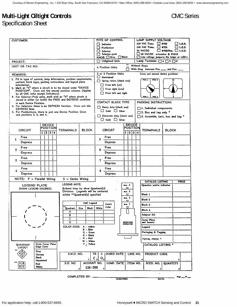
Multi-Light Oiltight Controls CMC SeriesSpecification Sheet
For application help: call 1-800-537-6945. Honeywell 1 MICRO SWITCH Sensing and Control 21
Courtesy of Steven Engineering , Inc. ! 230 Ryan Way, South San Francisco, CA 94080-6370 ! Main Office: (650) 588-9200 ! Outside Local Area: (800) 258-9200 ! www.stevenengineering.com

Multi-Light Oiltight Controls CMC SeriesCover Plates, Color Inserts, and Legend Plates
12 Honeywell 1 MICRO SWITCH Sensing and Control For application help: call 1-800-537-6945.
FAST ASSEMBLY LEGEND DISPLAYThe four selected color inserts snap intothe legend plate. This sub-assembly thensnaps into the cover plate to complete thefront-of-panel assembly.
FOR INDICATORS
COVER PLATE
LEGEND PLATE
COLOR INSERTS
FOR OPERATORINDICATORS
COVER PLATE
LEGEND PLATE
COLOR INSERTS
COVER PLATES AND COLORINSERTSCover plates and color inserts are offeredtogether in one package under a singlecatalog listing. The four color inserts canbe positioned in any of the four quarters ofthe total display area.
Any color combination you desire is in-cluded in this chart. The chart is arrangedin the following order: 4 same colors, 3 F1 colors, 2 F 2 colors, 2 F 1 F 1 colors,and 1 F 1 F 1 F 1 colors.
The cover plates listed in the tables have agray painted edge. Plates with edges oth-er than gray may be ordered by substitut-ing any of the following four digits in placeof the first four digits in the tables. Exam-ple: 906A — gray edge or 906E — blackedge. Listings are completed from thenext page.
Edge Operator-Color Indicator Indicator
Gray 906A 906BChrome 906C 906DBlack 906E 906FUnpainted 906G 906HRed 906J 906KWhite 906N 906P
CMC LEGEND PLATESLegend plates are transparent plasticparts on which word messages are dis-played.
BLANK PLATESBlank legend plates are available for cus-tomers preferring to do their own hotstamping, etching, engraving, or silkscreening of legend plates. Drafting my-lar or film positives can also be positionedon the legend plate for custom panel ap-pearance.
LEGENDEDLegend plates are offered with letteringpositioned horizontally, vertically, or diag-onally — in combinations of black andwhite lettering — in combinations of threedifferent type sizes — and the messagethe customer specifies. (See charactercount chart, page 16.) These plates areordered on Custom Legend Form onpage 22.
See completed sample page 17.
LEGEND CONTRASTFor maximum visibility in both the lightedand unlighted condition, the chart belowis recommended as a guide.
ColorLegend LetteringSnap in
Inserts White Black
Amber X X
Blue X
Green X
Red X
White X
Yellow X
BLANK LEGEND PLATES
INDICATOR OPERATOR
907AYY100 907BYY100
LEGENDED PLATES
907AUS 907BUS
Courtesy of Steven Engineering , Inc. ! 230 Ryan Way, South San Francisco, CA 94080-6370 ! Main Office: (650) 588-9200 ! Outside Local Area: (800) 258-9200 ! www.stevenengineering.com

Multi-Light Oiltight Controls CMC SeriesGray Cover Plate and Color Insert Color Guide / Incandescent Lamps
For application help: call 1-800-537-6945. Honeywell 1 MICRO SWITCH Sensing and Control 13
COLOR CODE: A—Amber B—Blue G—Green R—Red W—White Y—Yellow K—BlackCover Plate & Color Cover Plate & Color Cover Plate & Color Cover Plate & ColorInserts For Indicator Inserts For Operator Inserts For Indicator Inserts For Operator
Units Only Color Code Indicator Units Units Only Color Code Indicator Units
906 AAF AAAA 906 BAF906 AAD BBBB 906 BAD906 AAC GGGG 906 BAC906 AAA RRRR 906 BAA906 AAE WWWW 906 BAE
906 AAB YYYY 906 BAB906 AEH AAAB 906 BEH906 AEK AAAG 906 BEK906 AEJ AAAR 906 BEJ906 AED AAAW 906 BED
906 AFG AAAY 906 BFG906 AFD BBBA 906 BFD906 AFC BBBG 906 BFC906 AFA BBBR 906 BFA906 AEE BBBW 906 BEE
906 AFB BBBY 906 BFB906 AEZ GGGA 906 BEZ906 AEX GGGB 906 BEX906 AEG GGGR 906 BEG906 AEY GGGW 906 BEY
906 AEW GGGY 906 BEW906 AER RRRA 906 BER906 AEP RRRB 906 BEP906 AEO RRRG 906 BEO906 AEC RRRW 906 BEC
906 AEN RRRY 906 BEN906 AEM WWWA 906 BEM906 AEF WWWB 906 BEF906 AEA WWWG 906 BEA906 AEL WWWR 906 BEL
906 AEB WWWY 906 BEB906 AFE YYYA 906 BFE906 AEU YYYB 906 BEU906 AET YYYG 906 BET906 AES YYYR 906 BES
906 AEV YYYW 906 BEV906 ABN AABB 906 BBN906 ABM AAGG 906 BBM906 ABL AARR 906 BBL906 ABP AAWW 906 BBP
906 AJF AAKK 906 BJF906 ABQ AAYY 906 BBQ906 ABH BBGG 906 BBH906 ABC BBRR 906 BBC906 ABK BBWW 906 BBK
906 AJD BBKK 906 BJD906 ABF BBYY 906 BBF906 ABB GGRR 906 BBB906 ABJ GGWW 906 BBJ906 AJC GGKK 906 BJC
906 ABE GGYY 906 BBE906 ABD RRWW 906 BBD906 AJA RRKK 906 BJA906 ABA RRYY 906 BBA906 AJE WWKK 906 BJE
906 ABG WWYY 906 BBG906 AJB YYKK 906 BJB906 AGZ AABG 906 BGZ906 AGX AABR 906 BGX906 AGY AABW 906 BGY
906 AHL AABY 906 BHL906 ADG AAGR 906 BDG906 ADW AAGW 906 BDW906 AHK AAGY 906 BHK906 ADX AARW 906 BDX
906 AHJ AARY 906 BHJ906 AHM AAWY 906 BHM906 AGV BBAG 906 BGV906 AGS BBAR 906 BGS906 AGW BBAW 906 BGW
906 AHF BBAY 906 BHF906 AGR BBGR 906 BGR906 AGU BBGW 906 BGU906 ADS BBGY 906 BDS906 ADR BBRW 906 BDR906 AGP BBRY 906 BGP
906 AGT BBWY 906 BGT906 AGN GGAB 906 BGN906 ADU GGAR 906 BDU906 AGO GGAW 906 BGO906 AHG GGAY 906 BHG
906 AGK GGBR 906 BGK906 ADV GGBW 906 BDV906 AGL GGBY 906 BGL906 ADT GGRW 906 BDT906 ADN GGRY 906 BDN
906 AGM GGWY 906 BGM906 AGE RRAB 906 BGE906 AGC RRAG 906 BGC906 AGF RRAW 906 BGF906 AHH RRAY 906 BHH
906 ADL RRBG 906 BDL906 AGD RRBW 906 BGD906 ADZ RRBY 906 BDZ906 AGB RRGW 906 BGB906 ADO RRGY 906 BDO
906 AGA RRWY 906 BGA906 ADY WWAB 906 BDY906 ADH WWAG 906 BDH906 ADF WWAR 906 BDF906 AHE WWAY 906 BHE
906 ADK WWBG 906 BDK906 ADM WWBR 906 BDM906 ADE WWBY 906 BDE906 ADB WWGR 906 BDB906 ADD WWGY 906 BDD
906 ADA WWRY 906 BDA906 AHC YYAB 906 BHC906 AHB YYAG 906 BHB906 AHA YYAR 906 BHA906 AHD YYAW 906 BHD
906 ADP YYBG 906 BDP906 ADJ YYBR 906 BDJ906 AGJ YYBW 906 BGJ906 ADC YYGR 906 BDC906 AGH YYGW 906 BGH
906 AGG YYRW 906 BGG906 AKF KKYG 906 BKF906 AKG KKYB 906 BKG906 AKH KKYW 906 BKH906 AKJ KKYA 906 BKJ
906 AKK KKGB 906 BKK906 AKL KKGW 906 BKL906 AKM KKGA 906 BKM906 AKN KKBW 906 BKN906 AKP KKBA 906 BKP
906 AKR KKWA 906 BKR906 AKA KKRY 906 BKA906 AKB KKRG 906 BKB906 AKC KKRB 906 BKC906 AKD KKRW 906 BKD
906 AKE KKRA 906 BKE906 ACF ABGR 906 BCF906 ACJ ABGW 906 BCJ906 ACN ABGY 906 BCN906 ACH ABRW 906 BCH
906 ACL ABRY 906 BCL906 ACP ABWY 906 BCP906 ACG AGRW 906 BCG906 ACK AGRY 906 BCK906 ACO AGWY 906 BCO
906 ACM ARWY 906 BCM906 ACD BGRW 906 BCD906 ACA BGRY 906 BCA906 ACE BGWY 906 BCE906 ACC BRWY 906 BCC906 ACB GRWY 906 BCB
Additional variations with black inserts are available.
Courtesy of Steven Engineering , Inc. ! 230 Ryan Way, South San Francisco, CA 94080-6370 ! Main Office: (650) 588-9200 ! Outside Local Area: (800) 258-9200 ! www.stevenengineering.com

Multi-Light Oiltight Controls CMC SeriesLED Cover Plates and Color Inserts
14 Honeywell 1 MICRO SWITCH Sensing and Control For application help: call 1-800-537-6945.
Cover plates, LEDs, and color inserts areoffered together in one package under asingle catalog listing. The four color in-serts can be positioned in any of the fourquarters of the total display area.
The cover plates listed in the tables have agray painted edge. Plates with edges oth-er than gray may be ordered by substitut-ing any of the adjacent four digits in placeof the first four digits in the tables. Exam-ple: 905A — gray edge or 905E — blackedge.
Edge Operator-Color Indicator Indicator
Gray 905A 905BChrome 905C 905DBlack 905E 905FUnpainted 905G 905HRed 905J 905KWhite 905N 905P
6 VAC/VDC LEDs, GRAY COVER PLATE AND COLOR INSERT ORDER GUIDECOLOR CODE: G—Green R—Red W—White Y—Yellow K—Black
Cover Plate & Color Cover Plate & Color Cover Plate & Color Cover Plate & ColorInserts For Indicator Inserts For Operator Inserts For Indicator Inserts For Operator
Units Only Color Code Indicator Units Units Only Color Code Indicator Units
905 AAA1 RRRR 905 BAA1905 AAB1 YYYY 905 BAB1905 AAC1 GGGG 905 BAC1905 ABA1 RRYY 905 BBA1905 ABB1 RRGG 905 BBB1905 ABD1 RRWW 905 BBO1905 ABE1 YYGG 905 BBE1905 ABG1 YYWW 905 BBG1905 ABJ1 GGWW 905 BBJ1905 ACB1 RGYW 905 BCB1905 ADA1 RYWW 905 BDA1905 ADB1 RGWW 905 BDB1905 ADC1 RYYG 905 BDC1905 ADD1 YGWW 905 BDD1905 ADN1 RYGG 905 BDN1905 ADO1 RRYG 905 BDO1905 ADT1 RGGW 905 BDT1905 AEA1 GWWW 905 BEA1905 AEB1 YWWW 905 BEB1905 AEC1 RRRW 905 BEC1905 AEG1 RGGG 905 BEG1905 AEL1 RWWW 905 BEL1905 AEN1 YRRR 905 BEN1905 AEO1 GRRR 905 BEO1905 AES1 RYYY 905 BES1905 AET1 GYYY 905 BET1905 AEV1 YYYW 905 BEV1905 AEW1 YGGG 905 BEW1905 AEY1 GGGW 905 BEY1905 AFK1 GGGK 905 BFK1905 AFL1 RKKK 905 BFL1905 AGA1 RRYW 905 BGA1905 AGB1 RRGW 905 BGB1905 AGG1 RYYW 905 BGG1905 AGH1 GYYW 905 BGH1905 AGM1 YGGW 905 BGM1905 AHN1 YYGK 905 BHN1905 AHO1 YGGK 905 BHO1905 AHP1 GGWK 905 BHP1905 AHQ1 RWWK 905 BHQ1905 AHS1 GWWK 905 BHS1905 AHT1 RGGK 905 BHT1905 AHY1 YYWK 905 BHY1
905 AJA1 RRKK 905 BJA1905 AJB1 YYKK 905 BJB1905 AJC1 GGKK 905 BJC1905 AKA1 RYKK 905 BKA1905 AKB1 RGKK 905 BKB1905 AKD1 RKKW 905 BKD1905 AKE1 YGKK 905 BKE1905 AKH1 RKKW 905 BKH1905 AKL1 GKKW 905 BKL1905 ALH1 RGWK 905 BLH1905 ALN1 RGYK 905 BLN1905 ALQ1 YKWW 905 BLQ1
Above listings include gray cover plate, 4 color inserts and one to four6 VAC/DC LEDs for all lighted quadrants. (R,G,Y). Black (K) and White(W) color inserts are normally not lighted so LEDs are not included.
Courtesy of Steven Engineering , Inc. ! 230 Ryan Way, South San Francisco, CA 94080-6370 ! Main Office: (650) 588-9200 ! Outside Local Area: (800) 258-9200 ! www.stevenengineering.com

Multi-Light Oiltight Controls CMC SeriesLED Cover Plates and Color Inserts
For application help: call 1-800-537-6945. Honeywell 1 MICRO SWITCH Sensing and Control 15
Cover plates, LEDs, and color inserts areoffered together in one package under asingle catalog listing. The four color in-serts can be positioned in any of the fourquarters of the total display area.
The cover plates listed in the tables have agray painted edge. Plates with edges oth-er than gray may be ordered by substitut-ing any of the adjacent four digits in placeof the first four digits in the tables. Exam-ple: 905A — gray edge or 905E — blackedge.
Edge Operator-Color Indicator Indicator
Gray 905A 905BChrome 905C 905DBlack 905E 905FUnpainted 905G 905HRed 905J 905KWhite 905N 905P
24 VAC/VDC LEDs, GRAY COVER PLATE AND COLOR INSERT ORDER GUIDECOLOR CODE: G—Green R—Red W—White Y—Yellow K—Black
Cover Plate & Color Cover Plate & Color Cover Plate & Color Cover Plate & ColorInserts For Indicator Inserts For Operator Inserts For Indicator Inserts For Operator
Units Only Color Code Indicator Units Units Only Color Code Indicator Units
905 AAA2 RRRR 905 BAA2905 AAB2 YYYY 905 BAB2905 AAC2 GGGG 905 BAC2905 ABA2 RRYY 905 BBA2905 ABB2 RRGG 905 BBB2905 ABD2 RRWW 905 BBD2905 ABE2 YYGG 905 BBE2905 ABG2 YYWW 905 BBG2905 ABJ2 GGWW 905 BBJ2905 ACB2 RGYW 905 BCB2905 ADA2 RYWW 905 BDA2905 ADB2 RGWW 905 BDB2905 ADC2 RYYG 905 BDC2905 ADD2 YGWW 905 BDD2905 ADN2 RYGG 905 BDN2905 ADO2 RRYG 905 BDO2905 ADT2 RGGW 905 BDT2905 AEA2 GWWW 905 BEA2905 AEB2 YWWW 905 BEB2905 AEC2 RRRW 905 BEC2905 AEG2 RGGG 905 BEG2905 AEL2 RWWW 905 BEL2905 AEN2 YRRR 905 BEN2905 AEO2 GRRR 905 BEO2905 AES2 RYYY 905 BES2905 AET2 GYYY 905 BET2905 AEV2 YYYW 905 BEV2905 AEW2 YGGG 905 BEW2905 AEY2 GGGW 905 BEY2905 AFK2 GGGK 905 BFK2905 AFL2 RKKK 905 BFL2905 AGA2 RRYW 905 BGA2905 AGB2 RRGW 905 BGB2905 AGG2 RYYW 905 BGG2905 AGH2 GYYW 905 BGH2905 AGM2 YGGW 905 BGM2905 AHN2 YYGK 905 BHN2905 AHO2 YGGK 905 BHO2905 AHP2 GGWK 905 BHP2905 AHQ2 RWWK 905 BHQ2905 AHS2 GWWK 905 BHS2905 AHT2 RGGK 905 BHT2905 AHY2 YYWK 905 BHY2
905 AJA2 RRKK 905 BJA2905 AJB2 YYKK 905 BJB2905 AJC2 GGKK 905 BJC2905 AKA2 RYKK 905 BKA2905 AKB2 RGKK 905 BKB2905 AKD2 RKKW 905 BKD2905 AKE2 YGKK 905 BKE2905 AKH2 RKKW 905 BKH2905 AKL2 GKKW 905 BKL2905 ALH2 RGWK 905 BLH2905 ALN2 RGYK 905 BLN2905 ALQ2 YKWW 905 BLQ2
Above listings include gray cover plate, 4 color inserts and one to four24 VAC/DC LEDs for all lighted quadrants. (R,G,Y). Black (K) andWhite (W) color inserts are normally not lighted so LEDs are not in-cluded.
Courtesy of Steven Engineering , Inc. ! 230 Ryan Way, South San Francisco, CA 94080-6370 ! Main Office: (650) 588-9200 ! Outside Local Area: (800) 258-9200 ! www.stevenengineering.com

Multi-Light Oiltight Controls CMC SeriesReplacement Parts
24 Honeywell 1 MICRO SWITCH Sensing and Control For application help: call 1-800-537-6945.
Cover PlatesOperator-
Indicators Color Indicators986 AAB 01 Gray 986 AAB 02986 AAB 03 Black 986 AAB 04986 AAB 05 Unpainted 986 AAB 06986 AAB 09 Red 986 AAB 10986 AAB 13 White 986 AAB 14986 AAB 07 Chrome 986 AAB 08
Bulk Packed Cover Platesfor IndicatorsCover plates for 20 CMCindicators are offered.
Bulk Packed Cover Platesfor Operator-IndicatorsPlates for 40 CMC operator-indicators are offered.
Specify in multiples of 20 Specify in multiples of 40986 AAB 01-BP 986 AAB 02-BP986 AAB 03-BP 986 AAB 04-BP986 AAB 05-BP 986 AAB 06-BP986 AAB 09-BP 986 AAB 10-BP986 AAB 13-BP 986 AAB 14-BP986 AAB 07-BP 986 AAB 08-BP
Individual Color Inserts for IncandescentEach insert covers 1⁄4 of total display — four required perCMC unit.
Operator-Indicators Color Indicators986 AAA 01 Red 986 AAA 02986 AAA 03 Yellow 986 AAA 04986 AAA 05 Green 986 AAA 06986 AAA 07 Blue 986 AAA 08986 AAA 09 White 986 AAA 10986 AAA 11 Amber 986 AAA 12986 AAA 13 Black3 986 AAA 14
Bulk Packed for IndicatorsIndividual color inserts (onecolor) for 5 CMC indicatorsare offered.
Bulk Packed for Operator-IndicatorsColor inserts (one color) for10 CMC operator-indicatorsare offered.
Specify in multiples of 20 Specify in multiples of 40986 AAA---BP 986 AAA---BP
Insert number of color above.
Individual Color Inserts for LEDsOperator-
Indicators Color Indicators985AAA01 Red 985AAA02985AAA03 Yellow 985AAA04985AAA05 Green 985AAA06986AAA09 White2 986AAA10986AAA13 Black3 986AAA14
REPLACEMENT LAMPSIndustry No. CatalogDescription Voltage Listing
755 6 PTZ40756 12 PTZ661819 24 PTZ67LED, Red 6VAC/DC PTZ69LED, Green 6VAC/DC PTZ70LED, Yellow 6VAC/DC PTZ68LED, Red 24VAC/DC PTZ78LED, Green 24VAC/DC PTZ79LED, Yellow 24VAC/DC PTZ71
‘‘O’’ Ring SealFor operator-indicatorsonly
986 BAA 04
Panel SealFor all units
986 BAA 03
Lamp Holder908 909 thru 914
Indicator Operator-Only Indicators
986 BAA 05 986 BAA 06
Lamp Box WithoutLamp Hardware
910 Selector 911 Selector- 908Series Push Series Indicators
986 BAA 24 986 BAA 25 986 BAA 27
Knobs1
Replacement 910 Series 913 SeriesKnob Packet For Gray Knob Black Knob
Selector, Positions 1-2-3-4 986BAA15 986BAA20
Selector, Positions 9-12-3-6 o’clock 986BAA17 986BAA22
Replacement 911 Series 914 SeriesKnob Packet For Gray Knob Black Knob
Selector-push, Position 1-2-3-4 986BAA16 986BAA21
Selector-push, Positions 9-12-3-6 o’clock 986BAA18 986BAA23Notes: 1, Knob packets include knob, shaft, and O-ring seal.
2, White inserts not recommended for illumination by LEDs.3, Black inserts not suitable for illumination.
Voltage ControlFor LampIndividual Units
986 BAA 01
120 VAC transformer
986 BAA 02
240 VAC transformer
986 BAA 07
Low voltage jumper
986 BAA 08
48 volt resistor
986 BAA 14
24V resistor
Courtesy of Steven Engineering , Inc. ! 230 Ryan Way, South San Francisco, CA 94080-6370 ! Main Office: (650) 588-9200 ! Outside Local Area: (800) 258-9200 ! www.stevenengineering.com

Multi-Light Oiltight Controls CMC SeriesContact Blocks
4 Honeywell 1 MICRO SWITCH Sensing and Control For application help: call 1-800-537-6945.
1 PTC heavy duty and electronic dutycontact blocks
1 Tandem mounting in any combinationup to four contact blocks per operator.(Two blocks on spring return devices.)
1 Exclusive four plunger adapter kit maybe used with selector and selector-push units for greater circuit flexibility.
HEAVY DUTY UL/CSA ListedHeavy duty contact blocks contain finesilver, butting-type contacts. Terminalsare angled 30° for easy screwdriver ac-cess to terminal screws. Screws containself-lifting pressure plates for easy wiring.Holds bare wires of 12 to 16 gauge, either
singly or two wires of same or adjacentsize. Crimp on spade or ring lugs can beused. Base of contact block has markedpad for pencil identification of the controlfrom back of panel.
TWO CIRCUIT BLOCKS ORDER GUIDE
GoldButting Contacts Silver Plated
Cata- Cata-log log
Description Symbol Listing Listing
1 NC-1 NO PTCB PTCT
1 NO PTCD
1 NC PTCE
1 NO-1 NO PTCF
1 NC-1 NC PTCG
For AC use only. Overlapping PTCJFor use with 909 LONC-pushbuttons. ECNO
For other appli- Sequencing PTCKcations contact ECNO-NOMICRO SWITCH.
LO J late opening EC J early closing
FOUR CIRCUIT BLOCKS ORDER GUIDE
GoldButting Contacts Silver Plated
Cata- Cata-log log
Description Symbol Listing Listing
2NC-2NO PTCC PTCW
1 NC PTCH1 NO
1 NC PTCU1 NO
ELECTRICAL RATINGS
AC Volts DC Volts35% Power Factor Inductive Load
ContinuousCurrent
10 Amps. Carry 120 240 480 600 125 250
Normal InrushCurrent in Amps. 60 30 15 12 — —
Normal BreakCurrent in Amps. 6 3 1.5 1.2 2.2 0.55
ELECTRONIC DUTYElectronic duty contact blocks contain sliding contacts for re-liable operation on electrical loads where thermal cleaning ac-tion is not present. These blocks are offered with silver contactsfor low energy applications or gold contacts for solid state milli-volt and milliamp dry circuits. Terminals are combination .187 x.021 inch quick connect plated for soldering.
SILVER GOLD
Sliding Contacts Silver GoldCata- Cata-log logList- List-
Description Symbol ing ing
4NC-4NO PTCL PTCP
2NC (Left half PTCM PTCR2NO of 2 plunger
version.)
2NC (Right half PTCN PTCS2NO of 2 plunger
version.)
ELECTRICAL RATINGS
Standard DutySliding Silver Contacts
AC Volts DC Volts35% Power Inductive
Factor LoadContinuous Current5 Amps. Carry 120 220 125 250
Normal Inrush Current in Amps. 30 15 — —
Normal Break in Amps. 3 1.5 1.1 .5
Gold Contacts
Maximum Resistive LoadsMaximum Volts in Amps.
28 VDC 1 Amp. Resistive
125 VAC .5 Amp Resistive
Initial contact resistance—.006 ohm average
Courtesy of Steven Engineering , Inc. ! 230 Ryan Way, South San Francisco, CA 94080-6370 ! Main Office: (650) 588-9200 ! Outside Local Area: (800) 258-9200 ! www.stevenengineering.com

Multi-Light Oiltight Controls CMC SeriesAccessories
For application help: call 1-800-537-6945. Honeywell 1 MICRO SWITCH Sensing and Control 23
Not all of the accessories listed here areavailable from MICRO SWITCH. Be sureto order from the suggested manufactur-er for each accessory.
COLOR FILTERS FOR LAMPSFor use over type lamps as furnished withCMC transformer units. Projects color in-dicated when used with white color in-serts and high ambient light level lampsshown at right.
LAMP INFORMATION120 VAC and 240 VAC transformer unitsare equipped with four T-3 1/4 #755lamps. The #755 lamp has a 6.3 volt rat-ing and is readily obtainable from all in-dustrial or automotive supply companies.These same units will accommodate the#1847 lamp. Replacement #755 lampscan be ordered as PTZ40.24 volt or 48 volt resistor units are sup-plied with lamps. 48 volt units areequipped with GE #1819 lamps rated at28 volts. 24 volt units are equipped with#756 lamps rated at 14 volts. Replace-ment #756 lamps can be ordered asPTZ66 and #1819 lamps can be orderedat PTZ67.CMC units containing line voltagejumpers are not supplied with lamps.These units are designed for use with any5 through 28 volt lamp listed.
If a lamp other than those listed is used,the lamp must be limited to 1 watt perquadrant.
QUICK CONNECTORSAvailable from suppliers shown (not soldby MICRO SWITCH)
ENCLOSURES FOR CMCNumerous panel manufacturers buildcabinets, panelboards or enclosures foruse with CMC. Your local MICRO SWITCHBranch Office or Authorized Distributorcan assist you with information on localavailability of enclosures.
PANEL PUNCH FOR CMCA 2N (50,8mm) square panel punch(Greenlee Model 731M) for CMC is manu-factured by Greenlee Tool Co., Rockford,Illinois. Use in conjunction with a Green-lee No. 7646 hydraulic punch driver.
Manufacturer Color Lamp Filters
Amber Red GreenAPM, Englewood, N.J. 1813/8 A-2 1813/8 R-4 1813/8 G-1
T–31⁄4 LAMP INFORMATION
Ambient Light Level
HighLamp Current Life Medium 24 FT—CType Voltage Amps (Hrs) 5-25 FT—C and Up
1850 5.0 .09 1,500 X
756 14.0 .08 15,000 X
1819 28.0 .04 2,500 X
1847 6.3 .15 5,000 X
47 6.3 .15 3,000 X
755 6.3 .15 20,000 X
T–31⁄4 LED INFORMATION
LED ColorVoltage
V AC/DCCurrent Amps
(Nominal)Luminous
Intensity (MCD)
White/Yellow 6 .06 75White/Yellow 24 .02 75
Green 6 .06 75Green 24 .02 75
Red 6 .06 85Red 24 .02 85
MCD – Millicandlea
FOR ELECTRONIC DUTY CONTACT BLOCKS(Either silver or gold contacts)
Range of Straight—NoManufacturer Wire Size Insulation Flag
AMP 20-16 42452-1 or 42486-1 or42452-2 42800-1
AMP 18-14 62016-2
HOLE PLUG
Contains Oiltight Seal2.25N (57,2mm) + 2.25N (57,2mm)986CAA01 Gray
SWITCH GUARD
Guard consists of cover plate and trans-parent cover. Switch cannot be operatedwhen cover guard is closed helping pre-vent accidental operation. Guard can beused on 909, 910 and 911 series oper-ators. Extends 1.52 in. (38,5 mm) frompanel.
Catalog Listing 986DAA01
Courtesy of Steven Engineering , Inc. ! 230 Ryan Way, South San Francisco, CA 94080-6370 ! Main Office: (650) 588-9200 ! Outside Local Area: (800) 258-9200 ! www.stevenengineering.com

Multi-Light Oiltight Controls CMC SeriesMounting Dimensions
For application help: call 1-800-537-6945. Honeywell 1 MICRO SWITCH Sensing and Control 25
Note: The location arrow on the contactblock must be lined up with the arow onthe operator, except as noted for thePTCB block on the ordering pages.
CMC WEIGHTIndicators and operator-indicators (in-cludes cover plate, legend plate, and col-or inserts). With transformers — 14 oz.max.
Without transformers — 71⁄2 oz. max.Contact blocks — 2 oz. each.4-Plunger Adapter Kit — 1 oz.
INDICATOR
PUSHBUTTON
SELECTOR
SELECTOR-PUSH
PANEL CUTOUT RECOMMENDATIONS
HORIZONTAL MOUNTING VERTICAL MOUNTING HORIZONTAL or VERTICAL5 TERMINAL CONSTRUCTION 5 TERMINAL CONSTRUCTION 8 TERMINAL CONSTRUCTION
Courtesy of Steven Engineering , Inc. ! 230 Ryan Way, South San Francisco, CA 94080-6370 ! Main Office: (650) 588-9200 ! Outside Local Area: (800) 258-9200 ! www.stevenengineering.com

Manual Switches PB SeriesPushbutton Switches
For application help: call 1-800-537-6945. Honeywell 1 MICRO SWITCH Sensing and Control 125
FEATURES1 Compact size1 Up to 4-poles1 Sealed versions
TOUCH FEEDBACK SWITCHES
SHORT TRAVEL SWITCHES
PANEL SEALED SWITCHES
ORDER GUIDEMomentary and alternate action switches.
No. of SPDT Circuits2 2 4 4
Button Mom. Alt. Mom. Alt.Color Action Action Action Action
Black 2PB11-T2 82PB19-T2 — 84PB19-T2
2PB732-T2 — 4PB714-T2 —(M8805/23-001) (M8805/23-003)
Red 2PB12-T2 82PB21-T2 — —
2PB717-T2 — 4PB717-T2 —(M8805/23-002) (M8805/23-004)
Green 2PB273-T2 82PB22-T2 — —
ORDER GUIDEMomentary action switches.
Button No. of SPDT CircuitsColor 2 3
Black 2PB7 3PB7
These switches resemble the touch-feed-back design, but have a flexible leaf ac-tuator for lower operating force and short-er button travel.
An elastomer seal is bonded between ac-tuating plunger and button collar. An O-ring seals the button assembly to the pan-el front.
Two-piece design enables button to bemounted separately. After switch unit iswired, it snaps into place from behindpanel.
ORDER GUIDEMomentary action switches.
No. of SPDT CircuitsButton CollarColor Type 1 2
Black Hex 1PB4 2PB4
Black Round 1PB42 —
Red Round 1PB43 2PB43
ELECTRICAL RATINGS(Except 15PB and 700PB)30 VDC: 5 amps, res., sea level or 50,000
ft.; 3 amps, ind., sea level; 2.5 ampsind., 50,000 ft; 24 amps, max. inrush.
UL and CSA rating for basic switches: 5amps, 125 or 250 VAC.
Push
butto
ns
Courtesy of Steven Engineering , Inc. ! 230 Ryan Way, South San Francisco, CA 94080-6370 ! Main Office: (650) 588-9200 ! Outside Local Area: (800) 258-9200 ! www.stevenengineering.com

Manual Switches PB SeriesPushbutton Switches
126 Honeywell 1 MICRO SWITCH Sensing and Control For application help: call 1-800-537-6945.
WATERTIGHT SWITCH ORDER GUIDEMomentary action switches.Has knurled chrome-finished facenut.
Button No. of SPDT CircuitsColor 2
Black 2PB901-T2
Facenut-to-panel, button-to-facenut, andbushing-to-facenut, sealing helps pre-vent entry of water from behind panel, upand over bushing wall. Switch units pot-ted in corrosion resistant metal enclo-sure. Meets submergence requirementsof MIL-STD-108 (up to 10 PSI water pres-sure for one hour).
HERMETICALLY SEALEDSWITCHES These pushbuttons are equipped with
HM hermetically sealed switch units,which have metal-to-metal fusion aroundthe cover, actuator base, and mountingholes. Terminals are sealed glass-to-metal.
Vapor-proof construction enables use indamp locations without condensation oncontacts. External parts corrosion resist-ant per MIL-S-8805. Meets explosion-proof requirements of MIL-S-8805.
ORDER GUIDEMomentary action switches.
No. of SPDT Circuits2 4
ButtonColor
Black 702PB1 704PB1
MINIATURE SIZE SWITCHES
1PB5 15PB2
ORDER GUIDEMomentary action switches.
No. of SPDT CircuitsButton 1 2
Steel* 1PB5 —
White Plastic — 15PB2
* Steel button enables use under hinged plates or paddle levers, in addition to manual operation.
ELECTRICAL RATINGS — 700PBand 15PB700PB (With hermetically sealed switchunits):28 VDC and 115 VAC, 400 HZ: 3 amps,ind., 5 amps, res.
15PB:30 VDC and 115 VAC: 2 amps, ind., 5amps. res.; 1.0 amp, lamp load.
1PB5250 VAC: 5 amps.
30 VDC: 5 amps, res., sea level or 50,000ft.; 3 amps, ind., sea level; 2.5 amps ind.,50,000 ft.; 24 amps, max. inrush.
Courtesy of Steven Engineering , Inc. ! 230 Ryan Way, South San Francisco, CA 94080-6370 ! Main Office: (650) 588-9200 ! Outside Local Area: (800) 258-9200 ! www.stevenengineering.com

Manual Switches PB SeriesPushbutton Switches
For application help: call 1-800-537-6945. Honeywell 1 MICRO SWITCH Sensing and Control 127
MOUNTING DIMENSIONS (For reference only)
Touch Feedback Switches Panel Sealed Switches
2-Pole 4-Pole
Dim. ‘‘A’’ Mom. 16,8/.66 30,0/1.18(max.) Alt. Act. 17,3/.68 30,5/1.20
Dim. ‘‘B’’ Mom. 26,7/1.05 26,7/1.05
Alt. Act. 33,0/1.34 33,0/1.34
Short Travel Switches
2-Pole 3-Pole
Dim. ‘‘A’’ (max.) 17,0/.67 23,8/.94
1-Pole 2-Pole
Dim. ‘‘A’’ (max.) 11,7/.46 17,0/.67
Key:0,0 J mm
0.00 J inches
Push
butto
ns
Courtesy of Steven Engineering , Inc. ! 230 Ryan Way, South San Francisco, CA 94080-6370 ! Main Office: (650) 588-9200 ! Outside Local Area: (800) 258-9200 ! www.stevenengineering.com

Manual Switches PB SeriesPushbutton Switches
128 Honeywell 1 MICRO SWITCH Sensing and Control For application help: call 1-800-537-6945.
MOUNTING DIMENSIONS (For reference only)
Watertight Switch Miniature Size Switches
Hermetically Sealed Switches
Mounting hardware includes:hexnut, lockwasher, andkeying washer.
2-Pole 4-Pole
Dim. ‘‘A’’ (max.) 16,8/.66 30,0/1.18Key:
0,0 J mm
0.00 J inches
Courtesy of Steven Engineering , Inc. ! 230 Ryan Way, South San Francisco, CA 94080-6370 ! Main Office: (650) 588-9200 ! Outside Local Area: (800) 258-9200 ! www.stevenengineering.com
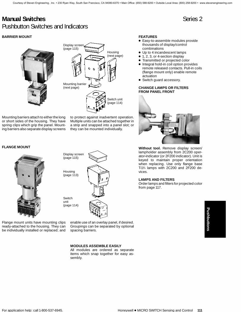
Manual Switches Series 2Pushbutton Switches and Indicators
For application help: call 1-800-537-6945. Honeywell 1 MICRO SWITCH Sensing and Control 111
FEATURES1 Easy-to-assemble modules provide
thousands of display/controlcombinations
1 Up to 4 incandescent lamps1 1, 2, 3, or 4-section display1 Transmitted or projected color1 Integral hold-in coil option provides
remote released contacts. Pull-in coils(flange mount only) enable remoteactuation
1 Switch guard accessory.
CHANGE LAMPS OR FILTERSFROM PANEL FRONT
Without tool. Remove display screen/lampholder assembly from 2C200 oper-ator-indicator (or 2F200 indicator). Unit iskeyed to maintain proper orientationwhen replacing. Use only flange baseT-13⁄4 lamps with 2C200 and 2F200 de-vices.
LAMPS AND FILTERSOrder lamps and filters for projected colorfrom page 117.
BARRIER MOUNT
Display screen(page 115)
Housing(next page)
Mounting barrier(next page)
Switch unit(page 114)
Mounting barriers attach to either the longor short sides of the housing. They havespring clips which grip the panel. Mount-ing barriers also separate display screens
to protect against inadvertent operation.Multiple units can be attached together ina strip and snapped into a panel slot; orthey can be mounted individually.
FLANGE MOUNT
Display screen(page 115)
Housing(page 113)
Switchunit(page 114)
Flange mount units have mounting clipsready-attached to the housing. They canbe individually installed or replaced; and
enable use of an overlay panel, if desired.Groupings can be separated by optionalspacing barriers.
MODULES ASSEMBLE EASILYAll modules are ordered as separateitems which snap together for easy as-sembly.
Push
butto
ns
Courtesy of Steven Engineering , Inc. ! 230 Ryan Way, South San Francisco, CA 94080-6370 ! Main Office: (650) 588-9200 ! Outside Local Area: (800) 258-9200 ! www.stevenengineering.com

Manual Switches Series 2Pushbuttons Switches and Indicators
112 Honeywell 1 MICRO SWITCH Sensing and Control For application help: call 1-800-537-6945.
Barriers on long sides
Barriers on short sides
BARRIER MOUNT MODULESBarrier mount assemblies are identical inpanel appearance. Operator-indicatorhousings have spring clips for attachingswitch modules. This feature is not pro-vided with indicator housings.
Barriers are necessary for mounting.They can be specified for attachment tothe long or short side of the housing, asstated in the order guides.
BARRIER MOUNT HOUSING ORDER GUIDESee ‘‘Application Data’’ for typical bailing circuits for coil-equipped modules.
Tool Not RequiredBarriersAttach On:
No. ofLamp Sockets Operator-Indicator Indicator Only
Long Sidesof Housing
2 (A & C) 2C2074 (A-D) 2C209
Short Sidesof Housing
2 (A & C) 2C2014 (A-D) 2C203 2F203
MOUNTING BARRIER ORDER GUIDEFor strip mounting, specify one more barrier than the number of units in the group.
Catalog ListingsMounting Barrier For PanelType Thickness Gray Black
Attach toLong Sides .06-.19 in. (1,52-4,83 mm) 2B2 2B4
Attach toShort Sides .06-.19 in. (1,52-4,83 mm) 2B1 2B3
Note: Panels .19 in. (1,52 mm) thick require the .06-.19 in. (1,52-4,83 mm) type barriers.
Courtesy of Steven Engineering , Inc. ! 230 Ryan Way, South San Francisco, CA 94080-6370 ! Main Office: (650) 588-9200 ! Outside Local Area: (800) 258-9200 ! www.stevenengineering.com

Manual Switches Series 2Pushbutton Switches and Indicators
For application help: call 1-800-537-6945. Honeywell 1 MICRO SWITCH Sensing and Control 113
Flanges on long sides
FLANGE MOUNT MODULESFlange mount assemblies are identical inpanel appearance. Operator-indicatorhousings have spring clips for switchmodules attachment (not provided withindicator housings).
Barriers are not required, since the panelmounting clips are ready-attached toflange sides of the housings. However,spacing barriers can be used for color-coding. They also aid in preventing inad-vertent operation of two screens with onepush.
Mounting dimensions on page 120.
FLANGE MOUNT HOUSING ORDER GUIDESee ‘‘Application Data’’ for typical bailing circuits for coil-equipped modules.
Tool Not Required
Flanges On:No. of Lamp
SocketsOperator-Indicator Indicator Only
Long Sides ofHousing
2 (A & C) 2C2044 (A-D) 2C206 2F206
SPACING BARRIER ORDER GUIDEFor .06-31 in. (1,5-7,9 mm) thick panels.
Catalog ListingsSpacing BarrierType Gray Black
For Long Flange Housing 2B9 2B18
Push
butto
ns
Courtesy of Steven Engineering , Inc. ! 230 Ryan Way, South San Francisco, CA 94080-6370 ! Main Office: (650) 588-9200 ! Outside Local Area: (800) 258-9200 ! www.stevenengineering.com

Manual Switches Series 2Pushbutton Switches and Indicators
114 Honeywell 1 MICRO SWITCH Sensing and Control For application help: call 1-800-537-6945.
SWITCH MODULESInterchangeable type 2D switch modulesattach to spring clips on the bottom of op-erator-indicator housings. There is a wideselection of circuitry, electrical ratings,operating actions and terminations.
For mounting dimensions, see page 121.
ELECTRICAL RATINGSilver contacts:30 VDC: 5 amps res. sea level or 50,000 ft,
3 amps ind. sea level, 2.5 amps 50,000 ft.Max. inrush, 24 amps.
UL and CSA rating for basic switch: 5amps, 125 or 250 VAC.
Gold contacts:30 VDC: 0.5 amp ind.,1amp res., sea level
and 50,000 ft. Max. inrush, 2 amps.
SM SUBMINIATURE MULTI-SPDT SWITCH MODULES
Momentary action Alternate action
SM switch modules offer a choice of twomomentary action styles, one with a pro-nounced touch-feedback, the other withlow operating force for rapid repeat ac-
tuation. Also available with alternate-action and combination momentary/alternate action modules. Extra lengthturret solder terminals.
SM SWITCH MODULE ORDER GUIDE
Momentary Action Alternate ActionTouch-Feedback Type Low Force TypeNo. of
SPDT Circuits Silver Contacts Silver Contacts
1 2D100 2D1182 2D2 2D264 2D9 2D33
V3 COMPACT SPDT/DPDT SWITCH MODULES
V3 switch modules have screw terminalswith lockwashers. Quick-connect termi-nals (not shown) are also available. Whenused with short-flange operator indica-tors, add spacing barriers to preventinterference.
ELECTRICAL RATING30 VDC: 10 amps ind.* sea level, 6 ampsind.,* 50,000 ft. Motor load, 6 amps.** ULand CSA rating for basic switch: 10 amps,1⁄3 Hp, 125 or 250 VAC; 1⁄2 amp, 125 VDC;1⁄4 amp, 250 VDC.* Inductive currents in accordance with AN3179.** Motor load rating based on starting current.
V3 SWITCH MODULE ORDER GUIDE
No. of SPDTCircuits Momentary Action
1 2D70
2 2D72
Courtesy of Steven Engineering , Inc. ! 230 Ryan Way, South San Francisco, CA 94080-6370 ! Main Office: (650) 588-9200 ! Outside Local Area: (800) 258-9200 ! www.stevenengineering.com

Manual Switches Series 2Pushbutton Switches and Indicators
For application help: call 1-800-537-6945. Honeywell 1 MICRO SWITCH Sensing and Control 115
ONE-PIECE DISPLAYSCREEN OPTIONS
Single-section
These translucent solid color displayscreens are single-section/one piececonstruction
SINGLE-SECTION/ONE-PIECE SCREENS ORDER GUIDE
Colors Standard
Red 2A1
Yellow 2A2
Green 2A3
White 2A5
THREE-PIECE DISPLAYSCREEN OPTIONS
Single-section
These screens have transparent coloredor colorless caps, transparent colorlesslegend inserts and translucent coloredbases.
SINGLE-SECTION/THREE-PIECESCREENS ORDER GUIDE
ColorlessColor Caps
Red 2A81
Yellow 2A82
Green 2A85
White 2A70
Amber 2A114
NOTE:Add –L to catalog listing if button is to belegended.
Silicone rubber baffles prevent light spillagefrom one section to another. Screen caps andlegend inserts are transparent colorless. Basesare translucent colored.
For more information on 2, 3, and 4-section dis-play screens, contact the MICRO SWITCH Ap-plication Center.
Push
butto
ns
Courtesy of Steven Engineering , Inc. ! 230 Ryan Way, South San Francisco, CA 94080-6370 ! Main Office: (650) 588-9200 ! Outside Local Area: (800) 258-9200 ! www.stevenengineering.com

Manual Switches Series 2Pushbutton Switches and Indicators
116 Honeywell 1 MICRO SWITCH Sensing and Control For application help: call 1-800-537-6945.
Courtesy of Steven Engineering , Inc. ! 230 Ryan Way, South San Francisco, CA 94080-6370 ! Main Office: (650) 588-9200 ! Outside Local Area: (800) 258-9200 ! www.stevenengineering.com
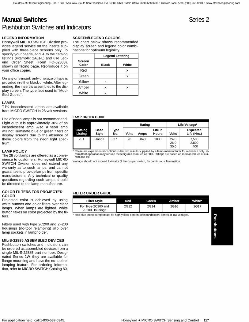
Manual Switches Series 2Pushbutton Switches and Indicators
For application help: call 1-800-537-6945. Honeywell 1 MICRO SWITCH Sensing and Control 117
LEGEND INFORMATIONHoneywell MICRO SWITCH Division pro-vides legend service on the inserts sup-plied with three-piece screens only. Tospecify your needs, add -L to the cataloglistings (example: 2A81-L) and use Leg-end Order Sheet (Form FO-62308),shown on facing page. Reproduce it onyour office copier.
On any one insert, only one size of type isprovided in either black or white. After leg-ending, the insert is assembled to the dis-play screen. The type face used is ‘‘Mod-ified Gothic’’.
LAMPST-13⁄4 incandescent lamps are availablefrom MICRO SWITCH in 28 volt versions.
Use of neon lamps is not recommended.Light output is approximately 30% of anincandescent lamp. Also, a neon lampwill not illuminate blue or green filters ordisplay screens due to the absence ofthese colors from the neon light spec-trum.
LAMP POLICYThe 28 volt lamps are offered as a conve-nience to customers. Honeywell MICROSWITCH Division does not extend anywarranty as to such lamps, and cannotguarantee to provide lamps from specificmanufacturers. Any technical or qualityquestions regarding such lamps shouldbe directed to the lamp manufacturer.
COLOR FILTERS FOR PROJECTEDCOLORProjected color is achieved by usingwhite buttons and color filters over clearlamps. When lamps are lighted, whitebutton takes on color projected by the fil-ters.
Filters used with type 2C200 and 2F200housings (no-tool relamping) slip overlamp sockets in lampholder.
MIL-S-22885 ASSEMBLED DEVICESPushbutton switches and indicators canbe ordered as assembled devices from asingle MIL-S-22885 part number. Desig-nated Series 2W, they are available forflange mounting and have the no-tool re-lamping feature. For ordering informa-tion, refer to MICRO SWITCH Catalog 80.
SCREEN/LEGEND COLORSThe chart below shows recommendeddisplay screen and legend color combi-nations for optimum legibility.
Legend Lettering
ScreenColor Black White
Red x
Green x
Yellow x
Amber x x
White x
LAMP ORDER GUIDE
Rating Life/Voltage†
Catalog Base Type Life in ExpectedListing Style No. Volts Amps Hours Volts Life (Hrs.)
2E1 Flange 327 28 .040 1000 24.0 7,50026.0 2,80030.0 400
† These are experimental continuous life test results supplied by a lamp manufacturer for reference only. In-termittent operation may reduce these figures as much as 50%. Ratings are based on median values of cur-rent and life.
Wattage should not exceed 2.4 watts (2 lamps) per switch, for continuous illumination.
FILTER ORDER GUIDE
Filter Style Red Green Amber White*
For Type 2C200 and 2G12 2G14 2G16 2G172F200 Housings
* Has blue tint to compensate for high yellow content of incandescent lamps at low voltages. Push
butto
ns
Courtesy of Steven Engineering , Inc. ! 230 Ryan Way, South San Francisco, CA 94080-6370 ! Main Office: (650) 588-9200 ! Outside Local Area: (800) 258-9200 ! www.stevenengineering.com

Manual Switches Series 2Pushbutton Switches and Indicators
118 Honeywell 1 MICRO SWITCH Sensing and Control For application help: call 1-800-537-6945.
SWITCH GUARD ACCESSORYA hinged cover on the switch guard helpsavoid inadvertent operation of the displayscreen. It is installed in place of the trans-parent slide-on cap furnished with three-piece screen. Note: When used with pull-in coil devices, specify the 2C200 oper-ator-indicator housings which have theno-tool relamping feature.
Barrier mount assembly with guard in-stalled. (Can also be used with all flangemount units.)
Guard requires a ‘‘lift-to-push’’ responseto operate switch normally.
Order Catalog Listing 2H20
Key:0,0 = mm
0.00 = inches
Courtesy of Steven Engineering , Inc. ! 230 Ryan Way, South San Francisco, CA 94080-6370 ! Main Office: (650) 588-9200 ! Outside Local Area: (800) 258-9200 ! www.stevenengineering.com

Manual Switches Series 2Pushbutton Switches and Indicators
For application help: call 1-800-537-6945. Honeywell 1 MICRO SWITCH Sensing and Control 119
MOUNTING DIMENSIONS (For reference only)
Long barrier operator-indicators Short barrier operator-indicators
Short barrier indicators Long barrier indicators Mounting barriers
Short Long
0,0 = mmKey:
0.00 = inches.
A Panel Thickness
1,5/.06 1,5-4,81/.06-.194,6/.18 4,8-7,9/.19-.31
Length Of Panel Cutout*
Number of UnitsType of Indicator orOperator-Indicator 1 2 3 4 5 6 7
Short mm 36,09 68,00 99,87 131,72 163,60 195,48 227,36
Barrier in. 1.421 2.677 3.932 5.186 6.441 7.696 8.951
Long mm 30,00 55,78 81,58 106,34 133,12 159,90 184,68
Barrier in. 1.181 2.196 3.212 4.226 5.241 6.256 7.271
*Nominal dimensions, ±0,25 mm/0.10 in. (In 5% ofthe cases, the cutout will be undersized for the build-up of assembled units and will require enlargement.
Push
butto
ns
Courtesy of Steven Engineering , Inc. ! 230 Ryan Way, South San Francisco, CA 94080-6370 ! Main Office: (650) 588-9200 ! Outside Local Area: (800) 258-9200 ! www.stevenengineering.com

Manual Switches Series 2Pushbutton Switches and Indicators
120 Honeywell 1 MICRO SWITCH Sensing and Control For application help: call 1-800-537-6945.
MOUNTING DIMENSIONS (For reference only)
Long flangeoperator-indicators
Long flange indicators Spacing barriers
Short Long
0,0 = mmKey: 0.00 = inches.
Length Of Panel Cutout*Add 4,19 mm/.165 in. to length for each optional spacing barrier used.
Number of UnitsType of Indicator orOperator-Indicator 1 2 3 4 5 6 7
Long mm 27,94 55,75 83,57 111,36 139,17 166,98 194,77
Flange in. 1.1 2.195 3.290 4.384 5.479 6.574 7.668
*Nominal dimensions, ±0,25 mm/0.10 in. (In 5% ofthe cases, the cutout will be undersized for the build-up of assembled units and will require enlargement.
Courtesy of Steven Engineering , Inc. ! 230 Ryan Way, South San Francisco, CA 94080-6370 ! Main Office: (650) 588-9200 ! Outside Local Area: (800) 258-9200 ! www.stevenengineering.com

Manual Switches Series 2Pushbutton Switches and Indicators
For application help: call 1-800-537-6945. Honeywell 1 MICRO SWITCH Sensing and Control 121
MOUNTING DIMENSIONS (For reference only)SM Switch Modules
V3 Switch Modules
Push
butto
ns
Courtesy of Steven Engineering , Inc. ! 230 Ryan Way, South San Francisco, CA 94080-6370 ! Main Office: (650) 588-9200 ! Outside Local Area: (800) 258-9200 ! www.stevenengineering.com

Manual Switches DM SeriesPushbutton Switches
122 Honeywell 1 MICRO SWITCH Sensing and Control For application help: call 1-800-537-6945.
FEATURES1 Attractive, rugged snap-in panel
mount design — easy installation.1 Snap-on or integral pushbuttons.1 Choice of momentary, alternate,
push-pull and pull-to-cheat operation.1 Quick-connect terminals.1 Expected mechanical life: 1 million
operations, 95% survival.1 Temperature range:
–35° to +180°F (–37° to 82°C)1 UL recognized, (E12252) CSA
certified (LR4442).
Three different styles of snap-on buttonscan be used with the DM switches shownabove. There is a choice of momentary oralternate-action, and single or double-pole circuitry.
ELECTRICAL RATINGUL and CSA rating: 10 amps, 1/2 Hp, 125,250 or 277 VAC.
SWITCHES WITH SNAP-ON BUTTONS
With button ‘‘A’’ With button ‘‘B’’
SPDT DPDT
SWITCH ORDER GUIDESwitches have gray faceplates. Buttonsare not included.
MomentaryCircuitry Action
SPDT 3DM1
DPDT 4DM1
Order buttons separately or ready-installed on switches from the order guidebelow.
SPDT
DPDT
SWITCH/BUTTON ORDER GUIDESwitches have gray faceplates.
Momentary Action Alternate ActionButtonStyle
ButtonColor
ButtonOnly
3DM1 (SPDT)and Button
4DM1 (DPDT)and Button
2003DM1 (SPDT)and Button
A
Black 31PA1 13DM1-A1 14DM1-A1
Red 13DM1-A2 14DM1-A2
B
Black 31PA3 13DM1-B1 14DM1-B1
Red 31PA4 13DM1-B2 — 2013DM1-B2
Courtesy of Steven Engineering , Inc. ! 230 Ryan Way, South San Francisco, CA 94080-6370 ! Main Office: (650) 588-9200 ! Outside Local Area: (800) 258-9200 ! www.stevenengineering.com
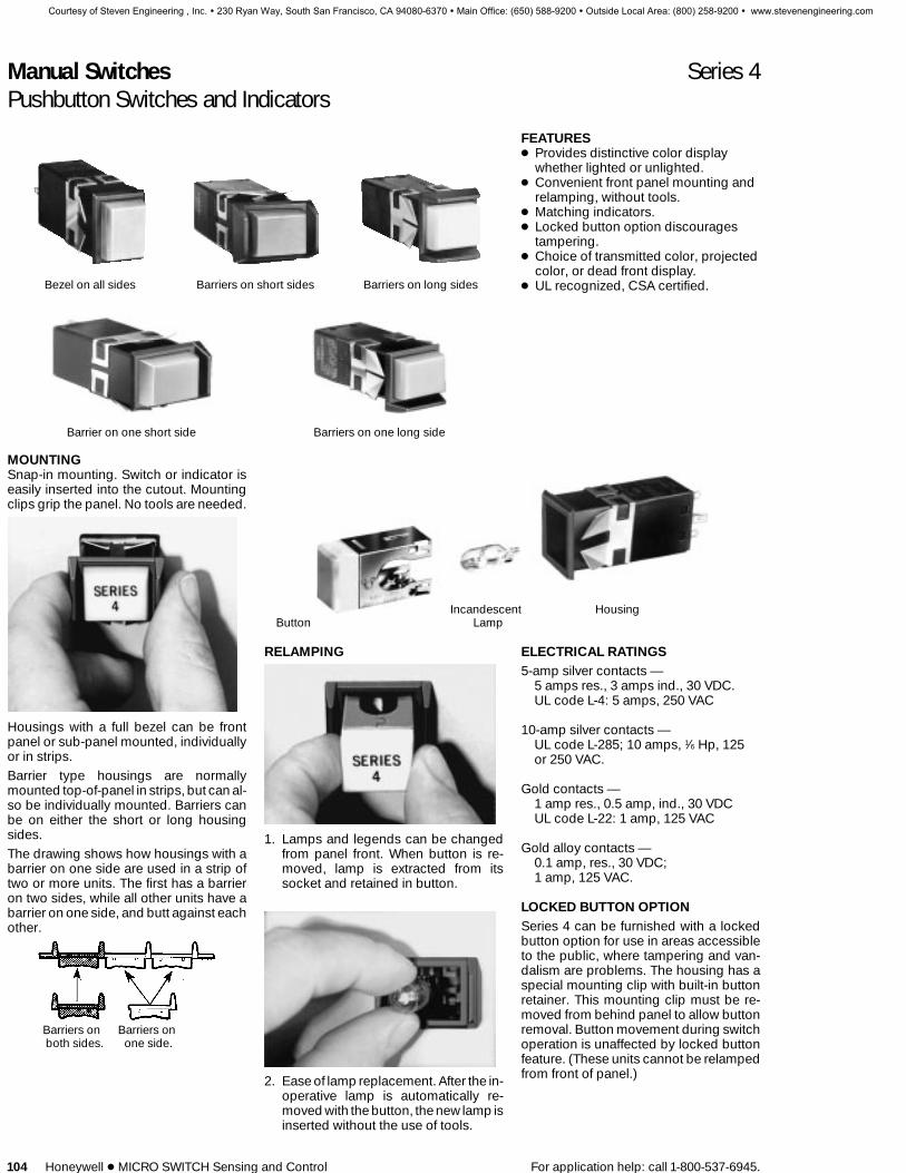
Manual Switches Series 4Pushbutton Switches and Indicators
104 Honeywell 1 MICRO SWITCH Sensing and Control For application help: call 1-800-537-6945.
Bezel on all sides Barriers on short sides Barriers on long sides
Barrier on one short side Barriers on one long side
FEATURES1 Provides distinctive color display
whether lighted or unlighted.1 Convenient front panel mounting and
relamping, without tools.1 Matching indicators.1 Locked button option discourages
tampering.1 Choice of transmitted color, projected
color, or dead front display.1 UL recognized, CSA certified.
MOUNTINGSnap-in mounting. Switch or indicator iseasily inserted into the cutout. Mountingclips grip the panel. No tools are needed.
Housings with a full bezel can be frontpanel or sub-panel mounted, individuallyor in strips.Barrier type housings are normallymounted top-of-panel in strips, but can al-so be individually mounted. Barriers canbe on either the short or long housingsides.The drawing shows how housings with abarrier on one side are used in a strip oftwo or more units. The first has a barrieron two sides, while all other units have abarrier on one side, and butt against eachother.
Barriers on Barriers onboth sides. one side.
Incandescent HousingButton Lamp
RELAMPING
1. Lamps and legends can be changedfrom panel front. When button is re-moved, lamp is extracted from itssocket and retained in button.
2. Ease of lamp replacement. After the in-operative lamp is automatically re-moved with the button, the new lamp isinserted without the use of tools.
ELECTRICAL RATINGS5-amp silver contacts —
5 amps res., 3 amps ind., 30 VDC.UL code L-4: 5 amps, 250 VAC
10-amp silver contacts —UL code L-285; 10 amps, 1⁄6 Hp, 125or 250 VAC.
Gold contacts —1 amp res., 0.5 amp, ind., 30 VDCUL code L-22: 1 amp, 125 VAC
Gold alloy contacts —0.1 amp, res., 30 VDC;1 amp, 125 VAC.
LOCKED BUTTON OPTIONSeries 4 can be furnished with a lockedbutton option for use in areas accessibleto the public, where tampering and van-dalism are problems. The housing has aspecial mounting clip with built-in buttonretainer. This mounting clip must be re-moved from behind panel to allow buttonremoval. Button movement during switchoperation is unaffected by locked buttonfeature. (These units cannot be relampedfrom front of panel.)
Courtesy of Steven Engineering , Inc. ! 230 Ryan Way, South San Francisco, CA 94080-6370 ! Main Office: (650) 588-9200 ! Outside Local Area: (800) 258-9200 ! www.stevenengineering.com

Manual Switches Series 4Pushbutton Switches and Indicators
For application help: call 1-800-537-6945. Honeywell 1 MICRO SWITCH Sensing and Control 105
SWITCH HOUSING ORDER GUIDE
Order buttons separately from page 116.
4A11B AA 11
Switching Element
TerminalsSwitch Housing Style Incandescent(Black) Electrical Data Action .110 QC PC* Illumination
11No lamp,
has lamp socket for T-31⁄4wedge base lamps.
21#161 12-voltT-31⁄4 lamp.
31#656 or 152
28-voltT-31⁄4 lamp
91Unlighted,
no lamp socket.
4A11BBezel: all sidesMtg. clips: long sides
4A12BBezel: all sidesMtg. clips: short sides
4A31BBarriers: long sidesMtg. clips: long sides
4A32BBarriers: long sidesMtg. clips: short sides
4A33BBarrier: one long sideMtg. clips: long sides
4A34BBarrier: one long sideMtg. clips: short sides
4A21BBarriers: short sidesMtg. clips: long sides
4A22BBarriers: short sidesMtg. clips: short sides
4A23BBarrier: one short sideMtg. clips: long sides
4A24BBarrier: one short sideMtg. clips: short sides
With Housing Provisionfor Locked Button
4A13BBezel: all sidesMtg. clips: long sides
4A25BBarriers: short sidesMtg. clips: long sides
4A26BBarrier: one short sideMtg. clips: long sides
4A35Barriers: long sidesMtg. clips: long sides
4A36Barrier: one long sideMtg. clips: long sides
1-Pole(SPDT),
5 a. silver contacts
Momentary
Alt. Action
AA
BA
AD
BD
2-Pole(DPDT),
5 a. silver contacts
Momentary
Alt. Action
EA
FA
ED
FD
1-Pole(SPDT),
gold contacts
Momentary
Alt. Action
CA
DA
CD
CD
2-Pole(DPDT),
gold contacts
Momentary
Alt. Action
GA
HA
GD
HD
1-Pole(SPDT),
10 a. silver contacts
Momentary
Alt. Action
LA
MA
2-Pole(DPDT),
10 a. silver contacts
Momentary
Alt. Action
NA
PA
1-Pole(SPDT),
gold alloy contacts
Momentary
Alt. Action
QA
RA
2-Pole(DPDT),
gold alloy contacts
Momentary
Alt. Action
TA
VA
Example:4A11BAA11Black switch housing with a bezel on allsides, mounting clips on long sides, 1-pole momentary-action 5-amp silver con-tacts, 110N quick-connect/solder termi-nals, and a T-31⁄4 lamp socket.
MOUNTING CLIP ORIENTATIONMounting clips on the long sides of thehousing are specified when individuallymounted or when the long sides of stripmounting housings parallel the longsides of the panel cutout slot. The mostsecure mounting is achieved when themounting clips are on the long sides.
Mounting clips on the short sides of thehousing are specified when short sides ofstrip mounted housings parallel the longsides of the panel cutout slot.
Courtesy of Steven Engineering , Inc. ! 230 Ryan Way, South San Francisco, CA 94080-6370 ! Main Office: (650) 588-9200 ! Outside Local Area: (800) 258-9200 ! www.stevenengineering.com

Manual Switches Series 4Pushbutton Switches and Indicators
106 Honeywell 1 MICRO SWITCH Sensing and Control For application help: call 1-800-537-6945.
HOW TO ORDER ASSEMBLEDSWITCHES OR INDICATORSWith lamp assembled:To order a lamp assembled, enter the ap-propriate ILLUMINATION Code Number,as shown in the lamp chart on the nextpage. Example: 4A11BBA12 is furnishedwith a 6-volt lamp installed.
With button assembled:To order a button assembled in the hous-ing, add the code letters for BUTTONTYPE, DISPLAY COLOR, and LEGEND(page 60) to the housing listing. Example:4A11BBA12AGN is furnished with a greentransmitted-color unlegended button as-sembled in the housing (and with a 6-voltlamp installed).
INDICATOR ORDER GUIDEOrder buttons separately from page 107.
4C11B 11
Indicator Housing Style (Black)
Terminals Incandescent
Description .110 Q.C. P.C. Illumination
11No lamp, has
lamp socket for T-31⁄4wedge base lamps.
21#161 12-voltT-31⁄4 lamp.
31#656 or 152
28-voltT-31⁄4 lamp
91Unlighted,
no lamp socket.
Bezel: all sides 4C11B 4D11BMtg. clips: long sides
Bezel: all sides 4C12B 4D12BBarriers: short sides
Barriers: short sides 4C21B 4D21BMtg. clips: long sides
Barriers: short sides 4C22B 4D22BMtg. clips: short sides
Barrier: one short side 4C23B 4D23BMtg. clips: long sides
Barrier: one short side 4C24B 4D24BMtg. clips: short sides
Barriers: long sides 4C31B 4D31BMtg. clips: long sides
Barriers: long sides 4C32B 4D32BMtg. clips: short sides
Barrier: one long side 4C33B 4D33BMtg. clips: long sides
Barrier: one long side 4C34B 4D34BMtg. clips: short sides
With Housing Provisionfor Locked Button
Bezel: all sides 4C13B 4D13BMtg. clips: long sides
Barriers: short side 4C25B 4D25BMtg. clips: long sides
Barrier: one short side 4C26B 4D26BMtg. clips: long sides
Barriers: long sides 4C35B 4D35BMtg. clips: long sides
Barrier: one long side 4C36B 4D36BMtg. clips: long sides
Example:4C11B11Black indicator housing with a bezel on allsides, mounting clips on long sides, 110Nquick-connect/solder terminals, and asocket for a T-31⁄4 lamp.
MOUNTING CLIP ORIENTATIONMounting clips on the long sides of thehousing are specified when individuallymounted or when the long sides of stripmounted housings parallel the long sidesof the panel cutout slot. The most securemounting is achieved when the mountingclips are on the long sides.
Mounting clips on the short sides of thehousing are specified when short sides ofstrip mounted housings parallel the longsides of the panel cutout slot.
Courtesy of Steven Engineering , Inc. ! 230 Ryan Way, South San Francisco, CA 94080-6370 ! Main Office: (650) 588-9200 ! Outside Local Area: (800) 258-9200 ! www.stevenengineering.com

Manual Switches Series 4Pushbutton Switches and Indicators
For application help: call 1-800-537-6945. Honeywell 1 MICRO SWITCH Sensing and Control 107
BUTTON ORDER GUIDE4B1 A G N
Button LegendWith Button Display (Legend Order Sheet must accompany
Metal Shell* Type Color all orders for legended buttons)
ATransmitted color.
5 sides lighted.1-piece translucent button.
BProjected color5 sides lighted.
Translucent white button& color insert.
CDead front,
5 sides lighted.Transparent black button& translucent color insert
DDead front,
Only face lighted.Transparent black button& translucent color insert.
ETransmitted color.
5 sides lighted.Transparent colorless
button &translucent color insert.
U, N, or K type only.
FTransmitted color.Only face lighted.
Transparent colorlessbutton & color insert.U, N or K type only.
GSame as type ‘‘A’’
except .250N higher
BStd. Blue
GStd. Green
RStd. Red
STransparent Black
(Unlightedapplications only)
YStd. Yellow
WStd. White
(Do not use withType B button)
AStd. Amber
(For use with Type Aor G button only)
UNo legend, button
(incl. insert) unassembled.(For customer who does own legending.)
Use with any button except 4B1A—
NNo legend, button assembled.
(For applications not requiring legends.)Use with any button.
LLegend on button only, button assembled.
(For customer who prefers to haveMICRO SWITCH provide legending.)Use with any button except E and F.
KLegend on insert only, button assembled.
(for C, D, E and F button types.)
JLegends on both button and insert,
button assembled.Use with C & D button types
4B2Both button and metal
shell provided.
Button WithMetal Shell,
WithProvision for
Locked Button*
4B3Both button and metal
shell provided.
ButtonWithout
Metal Shell
4B1Button only.
(without metal shell).For replacementpurposes only.
*To be ordered with switch.
LEGENDINGPad printed legendsUse Legend Order Sheet FO-63039 (seepage 110) to specify pad printed legends.Reproduce it on your office copier. Leg-ends are oversprayed for maximum dura-bility.
Film legendsFilm legends are not supplied by MICROSWITCH. However, this service is readilyavailable from commercial sources ormay be provided through your in-housecapabilities. The film should be polyesterto withstand lamp heat and must be preci-sion cut, per the dimensions shown onthe next page, to insure proper alignment.
The film fits into a small undercut on theface of the button insert. The film is heldsecurely when the outer button and insertare snapped together. (Note: It is difficultto disassemble for legend changes with-out damaging the parts.)
Button and insert should be snapped to-gether prior to being assembled to thebutton shell.
ButtonButton and metal shell
Example:4B1AGNGreen (transmitted color) unlegendedbutton. (If the button shell is also desired,substitute 4B2 for 4B1.) Note: legended button should be assem-
bled as shown above, with button notchkeyed to lamp removal slot in shell. Thiswill reduce possibility of lamp droppagewhen button is removed from the hous-ing. Buttons are legended in this manner.
Push
butto
ns
Courtesy of Steven Engineering , Inc. ! 230 Ryan Way, South San Francisco, CA 94080-6370 ! Main Office: (650) 588-9200 ! Outside Local Area: (800) 258-9200 ! www.stevenengineering.com
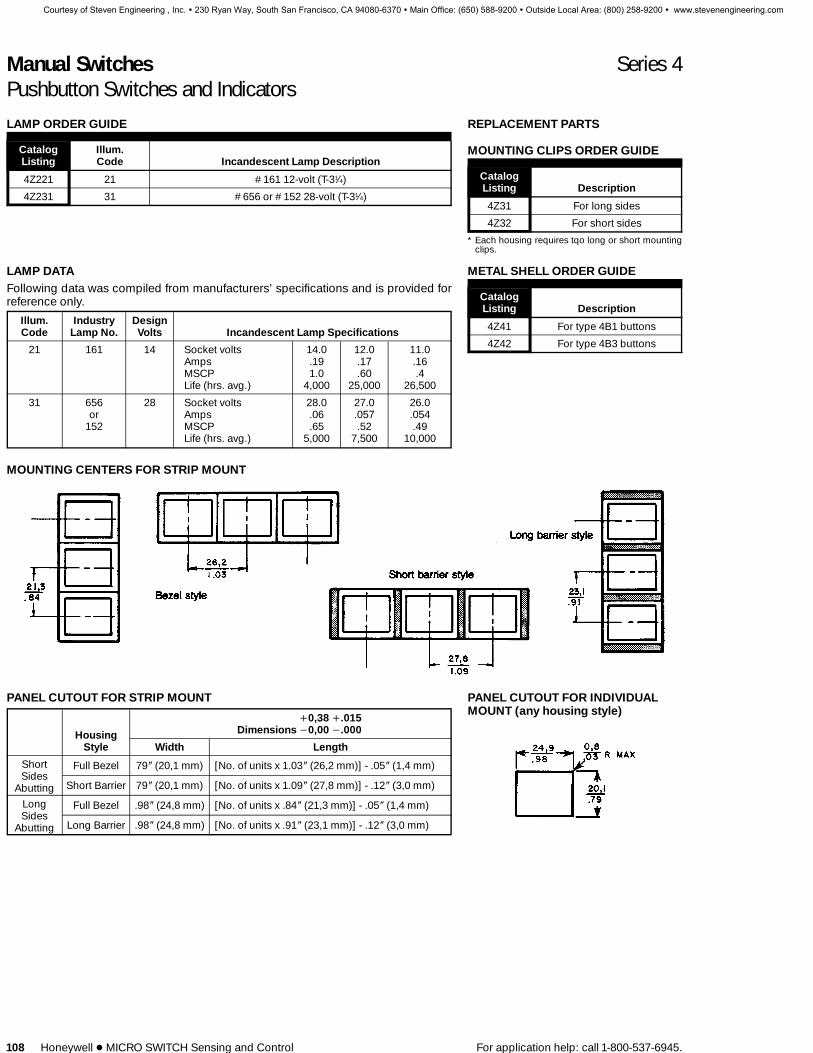
Manual Switches Series 4Pushbutton Switches and Indicators
108 Honeywell 1 MICRO SWITCH Sensing and Control For application help: call 1-800-537-6945.
LAMP ORDER GUIDE
Catalog Illum.Listing Code Incandescent Lamp Description
4Z221 21 #161 12-volt (T-31⁄4)
4Z231 31 #656 or #152 28-volt (T-31⁄4)
REPLACEMENT PARTS
MOUNTING CLIPS ORDER GUIDE
CatalogListing Description
4Z31 For long sides
4Z32 For short sides
* Each housing requires tqo long or short mountingclips.
LAMP DATAFollowing data was compiled from manufacturers’ specifications and is provided forreference only.
Illum. Industry DesignCode Lamp No. Volts Incandescent Lamp Specifications
21 161 14 Socket volts 14.0 12.0 11.0Amps .19 .17 .16MSCP 1.0 .60 .4Life (hrs. avg.) 4,000 25,000 26,500
31 656 28 Socket volts 28.0 27.0 26.0or Amps .06 .057 .054
152 MSCP .65 .52 .49Life (hrs. avg.) 5,000 7,500 10,000
METAL SHELL ORDER GUIDE
CatalogListing Description
4Z41 For type 4B1 buttons
4Z42 For type 4B3 buttons
MOUNTING CENTERS FOR STRIP MOUNT
PANEL CUTOUT FOR INDIVIDUALMOUNT (any housing style)
PANEL CUTOUT FOR STRIP MOUNT
+0,38 +.015Dimensions −0,00 −.000Housing
Style Width Length
ShortSides
Abutting
Full Bezel 79 N (20,1 mm) [No. of units x 1.03 N (26,2 mm)] - .05 N (1,4 mm)
Short Barrier 79 N (20,1 mm) [No. of units x 1.09 N (27,8 mm)] - .12 N (3,0 mm)
LongSides
Abutting
Full Bezel .98 N (24,8 mm) [No. of units x .84 N (21,3 mm)] - .05 N (1,4 mm)
Long Barrier .98 N (24,8 mm) [No. of units x .91 N (23,1 mm)] - .12 N (3,0 mm)
Courtesy of Steven Engineering , Inc. ! 230 Ryan Way, South San Francisco, CA 94080-6370 ! Main Office: (650) 588-9200 ! Outside Local Area: (800) 258-9200 ! www.stevenengineering.com

Manual Switches Series 4Pushbutton Switches and Indicators
For application help: call 1-800-537-6945. Honeywell 1 MICRO SWITCH Sensing and Control 109
MOUNTING DIMENSIONS (For reference only)
Terminal View
.110 QC terminal Printed circuitterminal
Quick-connect terminals are .110 N (2,8 mm) wideby .020 N (0,5 mm) thick. The slot is .130N (3,3 mm)long by .048 N (1,2 mm). Printed circuit terminalsare: Lamp — .025 (0,6 mm) by .020 N (0,5 mm):Switch — .025 N (0,6 mm) square.
All terminals are plated to permit soldering.
Panel thickness: .040-.200 in. (1,02-5,08 mm)
Key:0,0 = mm
0.00 = inches
For proper legend orientation, Series 4 switch when viewed from front of panel, shouldhave terminals1and 3 up for Figures1& 3 and to the right for Figures 2 and 4. (Figures1-4on Legend Order Sheet next page.)
Type A Button Type B Button Type C & E Buttons Type D & F Buttons(5 sides lighted) (5 sides lighted) (5 sides lighted) (Only face lighted)
Transparent Button Transparent ButtonTranslucent Translucent Type C-Black Type D-Black
Colored Button White Button Type-E Colorless Type F-Colorless
Type G Button(5 sides lighted)
Translucent Transparent Translucent Opaque Black InsertColored Button Colored Insert Colored Insert With Translucent
±.005/0,13Colored Face
*Thickness: .004 N to .007 N/0,1 to 0,18 (Film furnished by customer)
Push
butto
ns
Courtesy of Steven Engineering , Inc. ! 230 Ryan Way, South San Francisco, CA 94080-6370 ! Main Office: (650) 588-9200 ! Outside Local Area: (800) 258-9200 ! www.stevenengineering.com
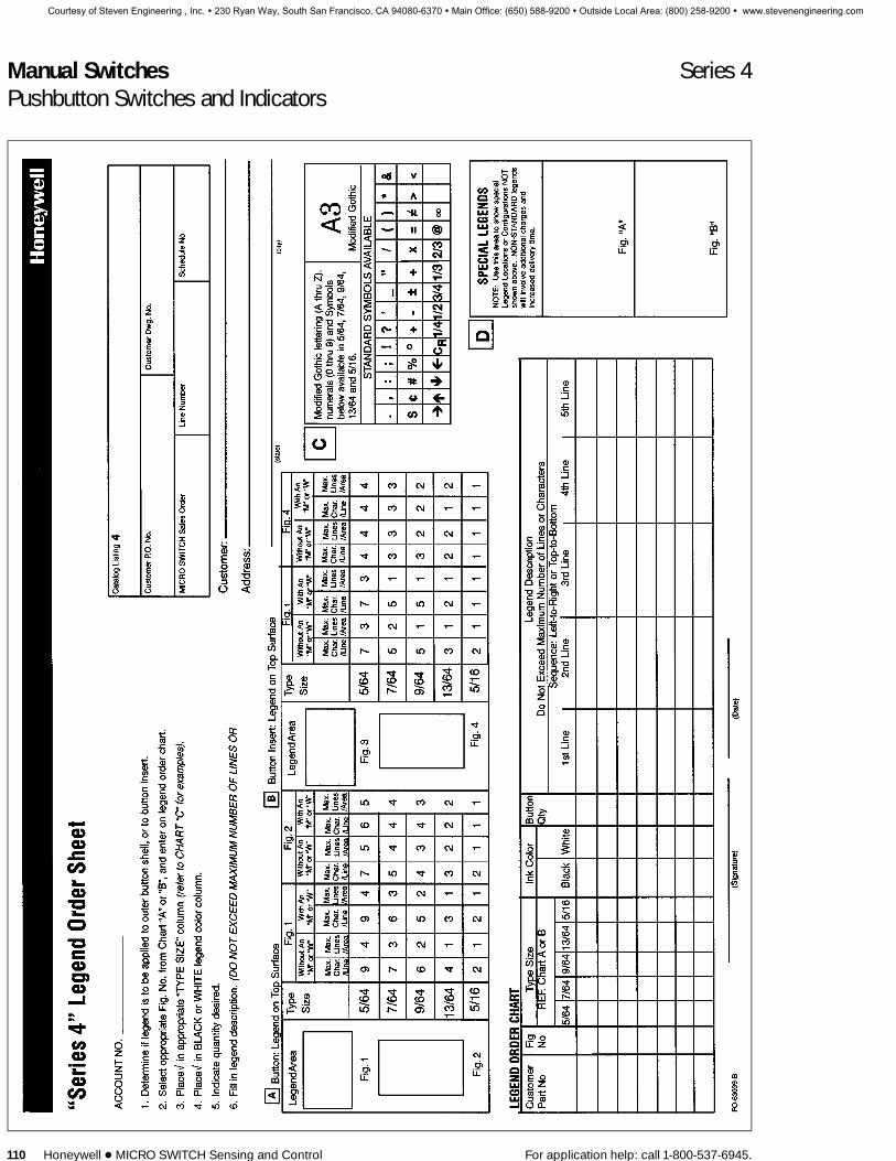
Manual Switches Series 4Pushbutton Switches and Indicators
110 Honeywell 1 MICRO SWITCH Sensing and Control For application help: call 1-800-537-6945.
Courtesy of Steven Engineering , Inc. ! 230 Ryan Way, South San Francisco, CA 94080-6370 ! Main Office: (650) 588-9200 ! Outside Local Area: (800) 258-9200 ! www.stevenengineering.com
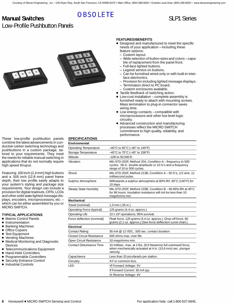
Manual Switches SLP1 SeriesLow-Profile Pushbutton Panels
8 Honeywell 1 MICRO SWITCH Sensing and Control For application help: call 1-800-537-6945.
FEATURES/BENEFITS1 Designed and manufactured to meet the specific
needs of your application – including thesefeature options:– Custom layout.– Wide selection of button sizes and colors – capa-
ble of replacement from the panel front.– Full-face lighted buttons.– Legend service on buttons.– Can be furnished wired-only or with built-in inter-
face electronics.– Provision for including lighted message displays.– Termination direct to PC board.– Custom enclosures available.
1 Tactile feedback of switching action.1 Low-cost installation – complete assembly is
furnished ready to attach with mounting screws.Mass termination to plug-in connector saveswiring time.
1 Low energy contacts – compatible withmicroprocessors and other low level logiccircuitry.
1 Advanced construction and manufacturingprocesses reflect the MICRO SWITCHcommitment to high quality, reliability, andperformance.
These low-profile pushbutton panelscombine the latest advancements in con-ductive rubber switching technology andpushbuttons in a custom package, tai-lored to your requirements. They meetthe needs for reliable manual switching inapplications that do not normally requirehigh speed thruput.
Featuring .100 inch (2,4 mm) high buttonsand a .505 inch (12,8 mm) panel framedepth, their low profile easily adapts toyour system’s styling and package sizerequirements. Your design can include aprovision for digital readouts, CRTs, LCDsand other solid state lighted message dis-plays, encoders, microprocessors, etc. –which can be either assembled by you orMICRO SWITCH.
TYPICAL APPLICATIONS1 Marine Control Panels1 Instrumentation1 Banking Machines1 Office Copiers1 Test Equipment1 Vending Machines1 Medical Monitoring and Diagnostic
Devices1 Telecommunications Equipment1 Hand-Held Controllers1 Programmable Controllers1 Security Entrance Control1 Industrial Controls
SPECIFICATIONSEnvironmentalOperating Temperature –40°C to 65°C (–40° to 149°F)
Storage Temperature –40°C to 70°C (–40° to 158°F)
Altitude –100 to 50,000 ft.
Vibration MIL-STD-202F, Method 204, Condition A – frequency to 500cycles: .06 in. double amplitude or 10 G’s and a frequencyrange of 10 to 500 cycles.
Shock MIL-STD-202F, Method 213B, Condition A – 50 G’s, 1/2 sine, 11millisecond pulse.
Sulphur Atmosphere Withstands a sulphur atmosphere at 80% RH. 60°C (140°F) for10 days
Steady State Humidity MIL-STD-202F, Method 103B, Condition B – 90-95% RH at 40°Cfor 96 hours. Insulation resistance will not be less than 10megohmns min.
MechanicalTravel (nominal) 1,3 mm (.05 in.)
Operating Force (typical) 125 grams (4.4 oz. approx.)
Operating Life 10 x 106 operations, 95% survival.
Force deflection (nominal) Peak force, 125 grams (4.4 oz. approx.); Drop-off force, 60grams (2.1 oz. approx.) (See force deflection curve chart.)
ElectricalContact Rating 30 mA @ 12 VDC, .500 sec. contact duration
Closed Circuit Resistance 500 ohms max. over life.
Open Circuit Resistance 10 megohmns min.
Contact Disturbance Time 10 millisec. max. at 2 lbs. (8,9 Newtons) full overtravel force,when mechanically actuated at 4 in. (10,6 mm) sec. plungervelocity.
Capacitance Less than 20 picofarads per station.
Circuitry X-Y or common bus.
LED Vf Forward Voltage: 5V
If Forward Current: 30 mA typ.
Vr Reverse Voltage: 4V
Courtesy of Steven Engineering , Inc. ! 230 Ryan Way, South San Francisco, CA 94080-6370 ! Main Office: (650) 588-9200 ! Outside Local Area: (800) 258-9200 ! www.stevenengineering.com
TED RUDOLPH
OBSOLETE

Manual Switches SLP1 SeriesLow-Profile Pushbutton Panels
For application help: call 1-800-537-6945. Honeywell 1 MICRO SWITCH Sensing and Control 9
SLP1 ORDER GUIDE (All possible combinations may not be available.)
SLP1 3 2 A 12 27—
Button Color1
SLP Series Circuitry Lighting Legend Matrix Unlighted LightedSLP1 2-XY
3-CommonBus
0-Unlighted1-Red LEDs
2-Green LEDs3-Yellow LEDs4-Combination
of LEDs
A-No LegendB-Legended
Black ink2
C-LegendedWhite ink2
D-LegendedBlack andWhite ink2
4-1×412-3×416-4×420-4×5
-10 Gray -25 Red-11 White -26 Yellow-12 Red -27 Green-13 Yellow -28 White-14 Green -29 Clear-15 Green (matcheslighted green)-16 Blue-18 Black
1 Factory will assign non-standard LED and button colors and combinations. Complete SLP Custom Order Sheet.2 SLP Custom Order Sheet must accompany order.
Example:SLP132A12-27 Common bus circuitry, green LEDS, no legend, 3×4 with green buttons.
INDIVIDUAL BUTTON CATALOGING
SLP51 A 20 G—
Open ColorButton Style Field Legending Unlighted Lighted
SLP51-UnlightedSLP52-Lighted
A 10-No legend20-Legended
Black ink1
21-LegendedWhite ink2
–R Red–G Green–U Green (matches
lighted green)–Y Yellow–B Blue–WWhite–K Black–A Gray
–R Red–U Green–Y Yellow–W White
1 SLP Custom Order Sheet must accompany order.
Example: SLP51A20-GGreen unlighted button legendedwith black ink.
CONSTRUCTIONThe top switching layer is a conductiverubber boot sheet (see cutaway draw-ing). When force is applied to a button,contact is made between the boot and thebottom circuit layer on a printed circuitboard. The boots impart an excellent tac-tile feedback (see force deflection curvechart).
A molded plastic housing, with panelslots for buttons and mounting holes ineach corner, is placed over all compo-nents and ultrasonically welded to theprinted circuit board. Interface circuitrycan be easily added to the PCB by the us-er or furnished built-in.
CUTAWAY VIEW
ILLUMINATIONFull face button lighting is provided byred, green, and yellow LEDs. (LED colorsshould be the same as the button they illu-minate.) The standard SLP1 offering is foruse under general office lighting condi-tions, which is usually about 80 foot can-dles. (LEDs with less brightness can beprovided.)
TERMINATIONA header type connector provides termi-nation directly from the printed circuitboard. Products shown here havestraight exit headers (see mounting di-mension drawings). Right angle exitheader connectors can also be furnished.Connector pins are .025 inch (0,64mm)square, on .100 inch (2,54 mm) centers,by .318 inch long. Suitable for use withvast array connector manufacturers’standard products.
Force Deflection Curve
Push
butto
nP
anels
Courtesy of Steven Engineering , Inc. ! 230 Ryan Way, South San Francisco, CA 94080-6370 ! Main Office: (650) 588-9200 ! Outside Local Area: (800) 258-9200 ! www.stevenengineering.com

Manual Switches SLP1 SeriesLow-Profile Pushbutton Panels
10 Honeywell 1 MICRO SWITCH Sensing and Control For application help: call 1-800-537-6945.
1 X 4 PANEL
Note: Connector pins are .418 in./10,6 mm long.
LIGHTEDWith C, Bus Sw. Cktry.
Station Switch LED Pins:No.s Pins: Pos. Neg.
1 3-8 1-52 4-8 2-53 6-8 10-54 7-8 9-5
NON-LIGHTED
Station SwitchNo. Pins
1 1-52 2-53 3-54 4-5
3 X 4 PANEL
Note: Connector pins are .418 in./10,6 mm long.
LIGHTED
With X-Y Sw. Cktry. With C. Bus Cktry.
Station Switch LED Pins: Switch LED Pins:Nos. Pins: Pos. Neg. Pins: Pos. Neg.
1 6-7 1-8 9-10 1-122 6-9 15-8 9-14 21-123 6-10 19-8 9-20 25-124 11-7 2-8 9-7 2-12
5 11-9 16-8 9-11 22-126 11-10 20-8 9-18 26-127 12-7 3-8 9-6 3-128 12-9 13-8 9-13 19-12
9 12-10 17-8 9-17 23-1210 14-7 4-8 9-8 4-1211 14-9 5-8 9-15 5-1212 14-10 18-8 9-16 24-12
NON-LIGHTED
With X-YStation Cktry. With C. Bus Ckty.Nos. Switch Pins: Switch Pins:
1 4-5 4-132 4-6 8-133 4-7 12-134 3-5 3-13
5 3-6 7-136 3-7 11-137 2-5 2-138 2-6 6-13
9 2-7 10-1310 1-5 1-1311 1-6 5-1312 1-7 9-13
Courtesy of Steven Engineering , Inc. ! 230 Ryan Way, South San Francisco, CA 94080-6370 ! Main Office: (650) 588-9200 ! Outside Local Area: (800) 258-9200 ! www.stevenengineering.com

Manual Switches SLP1 SeriesLow-Profile Pushbutton Panels
For application help: call 1-800-537-6945. Honeywell 1 MICRO SWITCH Sensing and Control 11
4 x 4 PANEL
Note: Connector pins are .418 in./10,6 mm long.
LIGHTED
With X-Y Sw. Cktry. With C. Bus Sw. Cktry.Station Switch LED Pins: Switch LED Pins:Nos. Pins: Pos. Neg. Pins: Pos. Neg.1 15-9 2-10 3-27 2-52 15-12 5-10 11-27 10-53 15-13 21-10 24-27 31-54 15-16 26-10 28-27 34-55 18-9 1-10 4-27 1-56 18-12 7-10 9-27 13-57 18-13 6-10 23-27 12-58 18-16 25-10 25-27 33-59 17-9 3-10 6-27 7-510 17-12 14-10 16-27 18-511 17-13 24-10 26-27 22-512 17-16 22-10 21-27 32-513 20-9 4-10 17-27 8-514 20-12 11-10 20-27 15-515 20-13 8-10 19-27 14-516 20-16 19-10 30-27 29-5
NON-LIGHTED
With X-YStation Cktry. With C. Bus Cktry.Nos. Switch Pins: Switch Pins:1 3-2 4-172 3-6 8-173 3-7 12-174 3-8 16-175 5-2 3-176 5-6 7-177 5-7 11-178 5-8 15-179 4-2 2-1710 4-6 6-1711 4-7 10-1712 4-8 14-1713 1-2 1-1714 1-6 5-1715 1-7 9-1716 1-8 13-17
5 X 4 PANEL
Note: Connector pins are .418 in./10,6 mm long.
NOTE:In addition to the recessed mounting hole style shown, units can befurnished with straight thru-holes for rear panel mounting or blind holesfor front panel mounting (see drawings below).
Rear Panel Mount Front Panel Mount
LIGHTED 5 x 4 PANEL
With X-Y Sw. Cktry. With C. Bus Cktry.Station Switch LED Pins: Switch LED Pins:Nos. Pins: Pos. Neg. Pins: Pos. Neg.1 15-7 3-23 3-38 7-282 15-8 2-23 8-38 2-283 15-13 1-23 22-38 1-284 14-21 29-23 32-38 41-285 15-26 30-23 37-38 33-286 19-7 4-23 4-38 10-287 19-8 9-23 15-38 11-288 19-13 18-23 21-38 19-289 19-21 25-23 31-38 30-2810 19-26 28-23 40-38 29-2811 17-7 5-23 5-38 9-2812 17-8 11-23 17-38 13-2813 17-13 16-23 24-38 20-2814 17-21 20-23 36-38 25-2815 17-26 27-23 42-38 34-2816 14-7 6-23 6-38 12-2817 14-8 10-23 18-38 14-2818 14-13 12-23 23-38 16-2819 14-21 22-23 35-38 26-2820 14-26 24-23 39-38 27-28
NON-LIGHTED
With X-YStation Cktry. With C. Bus Cktry.Nos. Switch Pins: Switch Pins:1 4-5 4-212 4-6 8-213 4-7 12-214 4-8 16-215 4-9 20-216 3-5 3-217 3-6 7-218 3-7 11-219 3-8 15-2110 3-9 19-2111 2-5 2-2112 2-6 6-2113 2-7 10-2114 2-8 14-2115 2-9 18-2116 1-5 1-2117 1-6 5-2118 1-7 9-2119 1-8 13-2120 1-9 17-21
Push
butto
nP
anels
Courtesy of Steven Engineering , Inc. ! 230 Ryan Way, South San Francisco, CA 94080-6370 ! Main Office: (650) 588-9200 ! Outside Local Area: (800) 258-9200 ! www.stevenengineering.com

Manual Switches SLP1 SeriesCustom Low-Profile Pushbutton Panels
12 Honeywell 1 MICRO SWITCH Sensing and Control For application help: call 1-800-537-6945.
MODULAR SWITCH DESIGNPROVIDES CUSTOM FLEXIBILITYThis new modular switch design incorpo-rates the same basic construction fea-tures as the MICRO SWITCH SLP push-button panel, plus gives you the flexibilityof specifying any switch matrix configura-tion.
Standard buttons are .583-inch square.Other button sizes can be furnished tosuit your application needs.
The modular switch construction featuresgood ergonomics with positive tactilefeedback which imparts a good feel of theswitching action, and compatibility withmicroprocessors and other low-level log-ic circuitry.
The addition of a polyurethane sheet, en-ables the SLP modular switch to meet wa-ter spray and dust sections of NEMA 12.
HOW TO SPECIFY CUSTOM ARRAYSUse the SLP Custom Order Sheet tospecify your desired button layout, buttoncolors, LED colors (unless buttons are tobe unlighted), and legend sizes and col-ors (unless the buttons are to be unleg-ended).
A copy of the order sheet is on the nexttwo pages. Reproduce it on your officecopier or request copies of formFO-64419.
Note: To enhance the display when thebuttons are to be lighted by LEDs, the but-tons should be either the same color asthe LEDs or white buttons.
APPLICATION ASSISTANCEOur field engineer/factory team will behappy to work with you every step of theway—through concept, design, andmanufacturing—to help insure your cus-tom package has a quality appearanceand performs just the way you want it.Contact the 800 number.
PANEL SEAL ACCESSORY
SLP 3 × 4 array with panel seal.
Elastomer silicon seals fit over SLP pan-els to help protect their circuitry and be-hind panel components from contami-nants that might enter through the switch.See photo. The seal is positioned be-tween rear mounted units and the user’smounting panel. When properly installed,it meets NEMA 13, providing a degree ofprotection against dust, spraying of wa-ter, oil, detergent, and non-corrosive coo-lant. (Installation instructions furnishedwith seals.)
Silicon has good natural resistance to ul-traviolet light and no UV inhibitors are re-quired. This material has been thoroughlyevaluated for chemical resistance. Forfurther information, contact the 800 num-ber. Use of the seal does not lessen oper-ating life.
Note:SLP panels with thru-hole mounting arerecommended for use with the panel seal.Sealing is most effective when mountingscrews are torqued to 6±1.5 in./lbs.
ORDER GUIDE – PANEL SEALS
Array Catalog Listing
1×4 SLP61-4
3×4 SLP61-12
4×4 SLP61-16
5×4 SLP61-20
Courtesy of Steven Engineering , Inc. ! 230 Ryan Way, South San Francisco, CA 94080-6370 ! Main Office: (650) 588-9200 ! Outside Local Area: (800) 258-9200 ! www.stevenengineering.com

Manual Switches SLP1 SeriesLow-Profile Pushbutton Panels
For application help: call 1-800-537-6945. Honeywell 1 MICRO SWITCH Sensing and Control 13
Push
butto
nP
anels
Courtesy of Steven Engineering , Inc. ! 230 Ryan Way, South San Francisco, CA 94080-6370 ! Main Office: (650) 588-9200 ! Outside Local Area: (800) 258-9200 ! www.stevenengineering.com

Manual Switches SLP1 SeriesLow-Profile Pushbutton Panels
14 Honeywell 1 MICRO SWITCH Sensing and Control For application help: call 1-800-537-6945.
Courtesy of Steven Engineering , Inc. ! 230 Ryan Way, South San Francisco, CA 94080-6370 ! Main Office: (650) 588-9200 ! Outside Local Area: (800) 258-9200 ! www.stevenengineering.com

Manual Switches SLP1 SeriesLow-Profile Pushbutton Panels
For application help: call 1-800-537-6945. Honeywell 1 MICRO SWITCH Sensing and Control 15
Push
butto
nP
anels
Courtesy of Steven Engineering , Inc. ! 230 Ryan Way, South San Francisco, CA 94080-6370 ! Main Office: (650) 588-9200 ! Outside Local Area: (800) 258-9200 ! www.stevenengineering.com

Manual Switches SN/SD SeriesHall Effect Keyboards/Modules
16 Honeywell 1 MICRO SWITCH Sensing and Control For application help: call 1-800-537-6945.
SD HALL EFFECT KEYBOARDSMICRO SWITCH SD Series Hall effectkeyboards meet high performance, cus-tom design, full-travel keyboard needs.They’re unsurpassed for switch speed,reliability and accuracy. Modular con-struction allows flexibility in keyboard lay-out and size.
Hall effect keyboards are offered in stan-dard profile and low profile, sealed or un-sealed, in standard arrays, and in customarrays tailored to fit the user’s specific ap-plication. Hall effect keyboards are capa-ble of handling very high throughput ap-plications.
A sealed version of the Hall effect key-board (101SD29-2E-S-H) designed forharsh duty industrial environments meetsNEMA 4 and 13 water/moisture resist-ance standards.
Request Product Sheets:26SD – 84-0250632SD – 84-0250263SD – 84-02504101SD – 84-0250112/16SD – 84-02607
SN/SD HALL EFFECT KEYSWITCHMODULESSN and SD Series keyswitch modules areideal for building custom arrays, such askeyboards, control/switch panels, andswitch matrices. Lighted display optionsare available.
SN modules are available in types thatcan be either snap-in panel mounted ormounted directly to printed circuit boardswithout additional mounting or supporthardware. Request Product Sheet 84-02508.
SD modules have a lower profile than SN.They securely mount in a metal grid platewhich provides support and enhancesgood keytop alignment between stationsand rows. Request Product Sheet 84-02505.
SD Grid Plate Mount
SN PC Board Mount
SN Snap-in Panel Mount
For further information on Hall effectkeyboards, keytops, and modules, con-tact your nearest MICRO SWITCH salesoffice. Or call 1-800-537-6945.
Courtesy of Steven Engineering , Inc. ! 230 Ryan Way, South San Francisco, CA 94080-6370 ! Main Office: (650) 588-9200 ! Outside Local Area: (800) 258-9200 ! www.stevenengineering.com
TED RUDOLPH
OBSOLETE

Courtesy of Steven Engineering, Inc.-230 Ryan Way, South San Francisco, CA 94080-6370-Main Office: (650) 588-9200-Outside Local Area: (800) 258-9200-www.stevenengineering.com

Courtesy of Steven Engineering, Inc.-230 Ryan Way, South San Francisco, CA 94080-6370-Main Office: (650) 588-9200-Outside Local Area: (800) 258-9200-www.stevenengineering.com