Honda GL1500 Gold Wing Motorcycles - Champion Trikes · Honda GL1500 Gold Wing Motorcycles Revision...
30
GL1500 TRIKE CONVERSION CHAMPION TRIKES Installation Guide Page 1 of 30 Revision 7 Illustrations / Photography By: Terry T. Emelio Tech. Writing By Terry T. Emelio Tech. Advisor: Jan Myburgh Trike Conversion Installation Guide for Honda GL1500 Gold Wing Motorcycles Revision 7 Champion Motorcycle Accessories International, Inc. dba Champion Sidecars 11841 Monarch Street, CA 92841 (800) 875-0949 (714) 847-0949 Fax (714) 847-1539 www.championtrikes.com CAUTION : Failure to follow these instructions can lead to serious personal injury and/or property damage and may void the warranty
-
Upload
trinhnguyet -
Category
Documents
-
view
332 -
download
3
Transcript of Honda GL1500 Gold Wing Motorcycles - Champion Trikes · Honda GL1500 Gold Wing Motorcycles Revision...

GL1500 TRIKE CONVERSION
CHAMPION TRIKES
Installation Guide Page 1 of 30 Revision 7 Illustrations / Photography By: Terry T. Emelio Tech. Writing By Terry T. Emelio Tech. Advisor: Jan Myburgh
Trike Conversion Installation Guide
for
Honda GL1500 Gold Wing Motorcycles Revision 7
Champion Motorcycle Accessories International, Inc. dba Champion Sidecars
11841 Monarch Street, CA 92841 (800) 875-0949 (714) 847-0949 Fax (714) 847-1539
www.championtrikes.com
CAUTION : Failure to follow these instructions can lead to serious personal injury and/or property damage and may void the warranty
GL1500 TRIKE CONVERSION
CHAMPION TRIKES
Installation Guide Page 2 of 30 Revision 7 Illustrations / Photography By: Terry T. Emelio Tech. Writing By Terry T. Emelio Tech. Advisor: Jan Myburgh
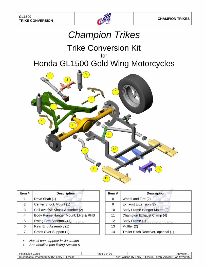
Champion Trikes
Trike Conversion Kit for
Honda GL1500 Gold Wing Motorcycles
Item # Description Item # Description 1 Drive Shaft (1) 8 Wheel and Tire (2) 2 Center Shock Mount (1) 9 Exhaust Extension (2) 3 Coil-over/Air Shock Absorber (2) 10 Body Frame Hanger Mount (2) 4 Body Frame Hanger Mount, LHS & RHS 11 Champion Exhaust Clamp (4) 5 Swing Arm Assembly (1) 12 Body Frame (1) 6 Rear End Assembly (1) 13 Muffler (2) 7 Cross Over Support (1) 14 Trailer Hitch Receiver, optional (1)
• Not all parts appear in illustration • See detailed part listing Section 5
GL1500 TRIKE CONVERSION
CHAMPION TRIKES
Installation Guide Page 3 of 30 Revision 7 Illustrations / Photography By: Terry T. Emelio Tech. Writing By Terry T. Emelio Tech. Advisor: Jan Myburgh
Table of Contents
1 GENERAL INFORMATION .................................................................................................................................. 4 1.1 Installation Information ..................................................................................................................................... 4 1.2 For Your Safety ................................................................................................................................................ 4 1.3 Important Safety Precautions .......................................................................................................................... 4 1.4 Specifications ................................................................................................................................................... 5
2 REMOVAL OF ORIGINAL PARTS ...................................................................................................................... 6 3 PREINSTALLATION PREPARATION ................................................................................................................. 7
3.1 Modification to Trunk / Luggage Stay .............................................................................................................. 7 3.2 Modification to Rear Inner Fender ................................................................................................................... 8 3.3 Install Residual Valve to Front Brake Master Cylinder .................................................................................... 9 3.4 Install Front Brake Cross Over Line ................................................................................................................. 9 3.5 Modification to Rear Brake System and Frame ............................................................................................. 10
4 INSTALL TRIKE CONVERSION KIT ................................................................................................................. 12 4.1 Install Champion Swing Arm .......................................................................................................................... 12 4.2 Install Champion Drive Shaft ......................................................................................................................... 13 4.3 Install Body Frame Top Mount and Center Shock Mount .............................................................................. 13 4.4 Install Shock Absorbers ................................................................................................................................. 14 4.5 Install Rear End Assembly ............................................................................................................................. 16 4.6 Install Air Lines to Shock System .................................................................................................................. 18 4.7 Reinstalling Reverse Resistor Assembly (1990 & Newer) ............................................................................. 19 4.8 Install Body Frame ......................................................................................................................................... 20 4.9 Install Trailer Hitch Receiver (Optional) ......................................................................................................... 21 4.10 Install Exhaust Extensions to Vehicle ........................................................................................................ 21 4.11 Install Mufflers............................................................................................................................................ 21 4.12 Bleed Rear Brake System ......................................................................................................................... 22 4.13 Install Trike Body to Vehicle ...................................................................................................................... 23 4.14 Install Wheels ............................................................................................................................................ 24 4.15 Modify and Install Seat .............................................................................................................................. 25
5 PARTS LIST 1500 HONDA TRIKE ................................................................................................................ 26 5.1 General .......................................................................................................................................................... 26 5.2 Drive Shaft ..................................................................................................................................................... 27 5.3 Exhaust System ............................................................................................................................................. 27 5.4 Rear Axle ....................................................................................................................................................... 27 5.5 Trailer Hitch .................................................................................................................................................... 28 5.6 Brakes ............................................................................................................................................................ 28
6 Fastener Part Numbers ...................................................................................................................................... 29 7 Fender Template ................................................................................................................................................ 30
GL1500 TRIKE CONVERSION
CHAMPION TRIKES
Installation Guide Page 4 of 30 Revision 7 Illustrations / Photography By: Terry T. Emelio Tech. Writing By Terry T. Emelio Tech. Advisor: Jan Myburgh
1 GENERAL INFORMATION The Champion Sidecars Trike Conversion Kit is designed with the utmost consideration to safety, quality and ease of installation. The kit comes complete with all necessary hardware and fasteners. However, it is assumed that the installer has advanced and/or professional skills in motorcycle servicing. It is recommended that installer obtain an OEM service manual for the vehicle on which the Trike Kit is to be installed.
1.1 Installation Information The information contained in this Installation Guide is intended for use by technicians of advanced and/or professional skill levels. Attempting installation without the proper training, tools and equipment could cause injury to you or others. It could also damage the vehicle or cause an unsafe condition.
1.2 For Your Safety Because this guide in intended for technicians of advanced to professional skill levels, we do not provide warnings about many basic shop safety practices. If you have not received shop safety training or do not feel confident about your knowledge of safety practices, we recommend that you do not attempt to perform the procedures described in this guide. Some of the most important general safety precautions are given below. Champion Sidecars cannot warn you of every conceivable hazard that can arise. Only you can decide whether or not you should perform a given task.
1.3 Important Safety Precautions
Make sure you have a clear understanding of all basic shop safety practices and that you wear appropriate clothing and use safety equipment. Be especially careful of the following:
• Read all directions before you begin, and make sure you have the tools, the parts and the skills required to
perform the tasks safely and completely.
• Protect your eyes by using proper safety glasses, goggles or face shields any time you hammer, drill, grind, pry or work around pressurized air or liquids, and springs or other stored-energy components.
• Use other protective wear when necessary, for example: gloves or safety shoes. Handling hot or sharp
parts can cause severe burns or cuts.
• Protect yourself and others when you have a vehicle up in the air. Anytime you lift a vehicle, either by hoist or a jack, make sure that it is securely supported.
1.3.1 Make sure the engine is turned off before you begin work.
• Carbon Monoxide poisoning from exhaust gases: Be sure there is adequate ventilation whenever you run the engine.
• Burns from hot parts: Let the engine and exhaust system cool before working on those areas.
GL1500 TRIKE CONVERSION
CHAMPION TRIKES
Installation Guide Page 5 of 30 Revision 7 Illustrations / Photography By: Terry T. Emelio Tech. Writing By Terry T. Emelio Tech. Advisor: Jan Myburgh
1.3.2 Injury from moving parts: If running the engine, keep hands, fingers and clothing away from moving/rotating parts.
• Gasoline vapor and hydrogen gases from batteries are explosive. To reduce the possibility of fire or
explosion, be careful when working near gasoline and batteries.
• Use only nonflammable solvent, not gasoline, to clean parts
• Never drain or store gasoline in an open container.
• Keep all cigarettes, sparks or flames away from the battery and all fuel-related parts.
1.4 Specifications
Overall Length: 110” Overall Width: 57.75” Wheel Base: 73” Load Capacity: 500 Lb Tire Size: 205 / 70 / R15 Wheel Size (15”) Offset +35 mm 15x7JJ 4x4.5 Tire Pressure: 20-25 PSI Suspension: Zero Flex Swing-Arm using Progressive 416 series air shocks and one OEM
adjustable air shock. Rear Differential: Champion lightweight rear axle / differential assembly. Gear Ratio: 2.93:1 Brakes: Original front plus 2 high performance disc brakes at rear. Front and rear
independently controlled. Storage Capacity: 6.75 cubic feet. 3 full-face helmets and additional storage.
GL1500 TRIKE CONVERSION
CHAMPION TRIKES
Installation Guide Page 6 of 30 Revision 7 Illustrations / Photography By: Terry T. Emelio Tech. Writing By Terry T. Emelio Tech. Advisor: Jan Myburgh
2 REMOVAL OF ORIGINAL PARTS Secure and raise motorcycle 9 to 10 inches using a quality motorcycle lift. Remove the following from the vehicle. See OEM manual for detailed instructions. Items to be retained for re-installation after modification are noted.
• Left and right side-covers (to be re-installed with minor modification).
• Seat (to be re-installed without modification).
• Trunk.
• Left and right passenger foot rests (to be re-installed without modification).
• Left and right side-covers above passenger foot rests.
• Battery and holder (to be re-installed without modification).
• Left and right saddle bags (retain side cover mounting grommets for re-use).
• Left and right mufflers.
• Rear wheel.
• Rear brake line to master cylinder.**
• Reverse resistor assembly (to be relocated).
• Swing Arm (Drive shaft boot will not be used).
• Bank angle sensor.
• Shocks. Air shock (non coil-over) to be reused. ** Thoroughly vacuum drain rear brake system, including feed line to left front caliper.
GL1500 TRIKE CONVERSION
CHAMPION TRIKES
Installation Guide Page 7 of 30 Revision 7 Illustrations / Photography By: Terry T. Emelio Tech. Writing By Terry T. Emelio Tech. Advisor: Jan Myburgh
3 PREINSTALLATION PREPARATION
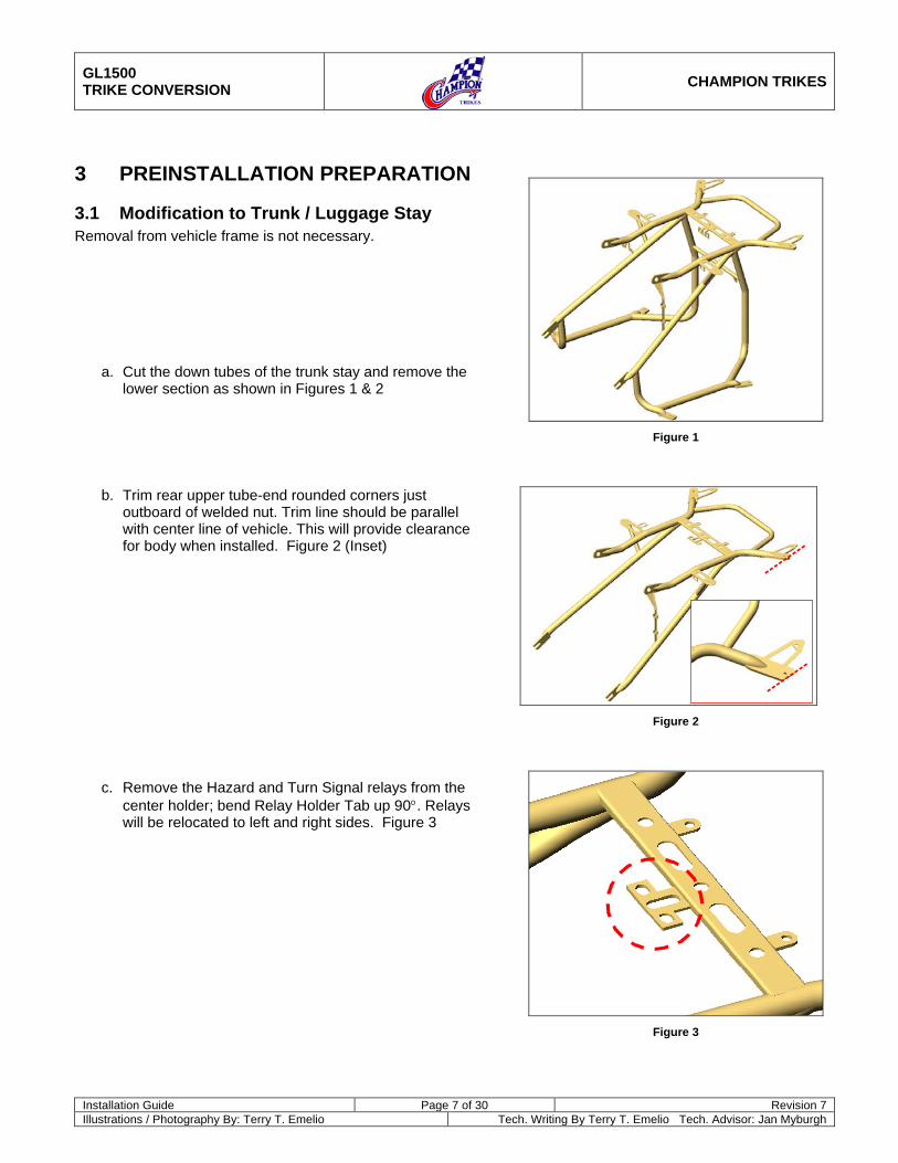
3.1 Modification to Trunk / Luggage Stay Removal from vehicle frame is not necessary.
a. Cut the down tubes of the trunk stay and remove the lower section as shown in Figures 1 & 2
b. Trim rear upper tube-end rounded corners just outboard of welded nut. Trim line should be parallel with center line of vehicle. This will provide clearance for body when installed. Figure 2 (Inset)
c. Remove the Hazard and Turn Signal relays from the center holder; bend Relay Holder Tab up 90°. Relays will be relocated to left and right sides. Figure 3
Figure 1
Figure 2
Figure 3
GL1500 TRIKE CONVERSION
CHAMPION TRIKES
Installation Guide Page 8 of 30 Revision 7 Illustrations / Photography By: Terry T. Emelio Tech. Writing By Terry T. Emelio Tech. Advisor: Jan Myburgh
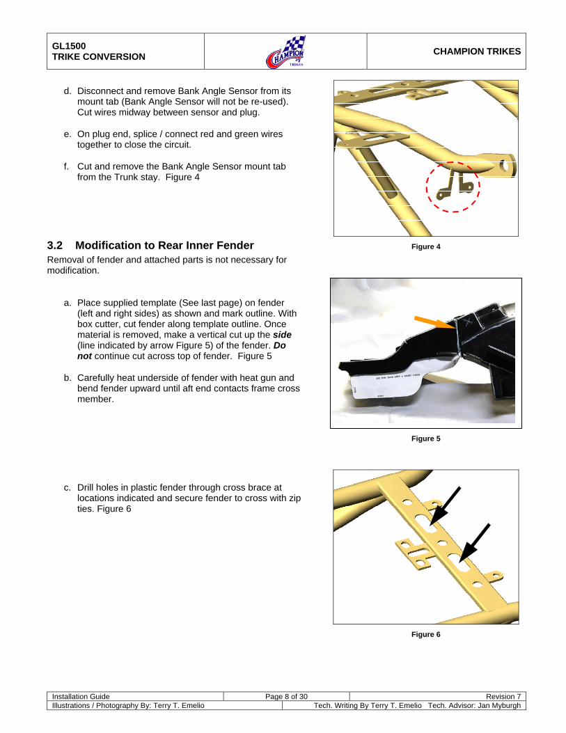
d. Disconnect and remove Bank Angle Sensor from its mount tab (Bank Angle Sensor will not be re-used). Cut wires midway between sensor and plug.
e. On plug end, splice / connect red and green wires together to close the circuit.
f. Cut and remove the Bank Angle Sensor mount tab from the Trunk stay. Figure 4
3.2 Modification to Rear Inner Fender Removal of fender and attached parts is not necessary for modification.
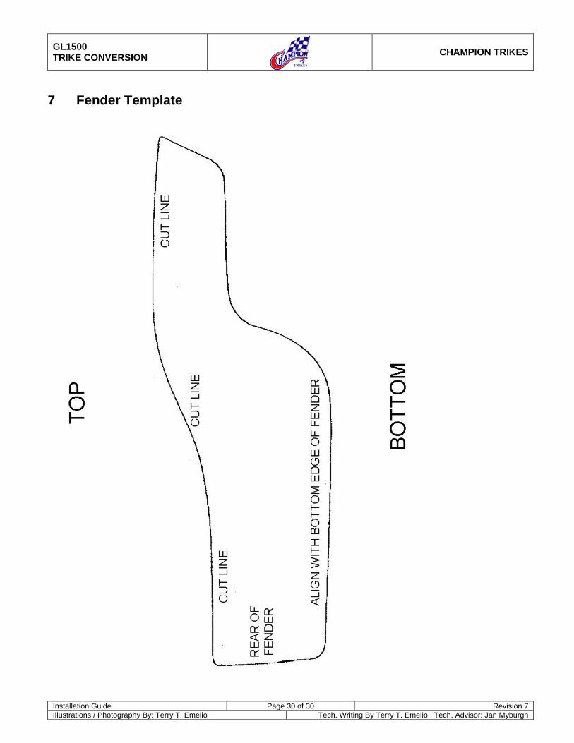
a. Place supplied template (See last page) on fender (left and right sides) as shown and mark outline. With box cutter, cut fender along template outline. Once material is removed, make a vertical cut up the side (line indicated by arrow Figure 5) of the fender. Do not continue cut across top of fender. Figure 5
b. Carefully heat underside of fender with heat gun and bend fender upward until aft end contacts frame cross member.
c. Drill holes in plastic fender through cross brace at locations indicated and secure fender to cross with zip ties. Figure 6
Figure 4
Figure 5
Figure 6
GL1500 TRIKE CONVERSION
CHAMPION TRIKES
Installation Guide Page 9 of 30 Revision 7 Illustrations / Photography By: Terry T. Emelio Tech. Writing By Terry T. Emelio Tech. Advisor: Jan Myburgh
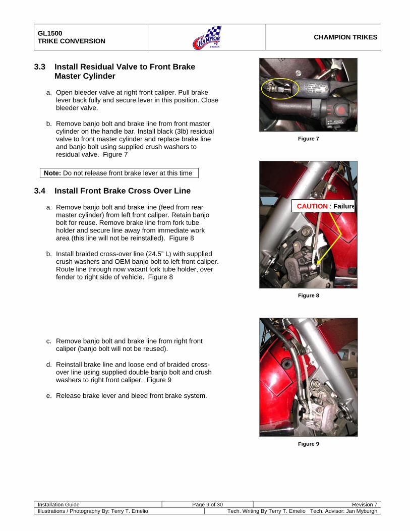
3.3 Install Residual Valve to Front Brake Master Cylinder
a. Open bleeder valve at right front caliper. Pull brake lever back fully and secure lever in this position. Close bleeder valve.
b. Remove banjo bolt and brake line from front master cylinder on the handle bar. Install black (3lb) residual valve to front master cylinder and replace brake line and banjo bolt using supplied crush washers to residual valve. Figure 7
Note: Do not release front brake lever at this time
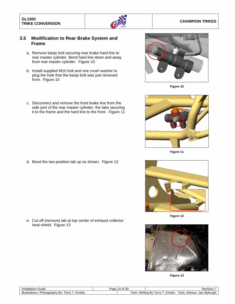
3.4 Install Front Brake Cross Over Line
a. Remove banjo bolt and brake line (feed from rear master cylinder) from left front caliper. Retain banjo bolt for reuse. Remove brake line from fork tube holder and secure line away from immediate work area (this line will not be reinstalled). Figure 8
b. Install braided cross-over line (24.5” L) with supplied crush washers and OEM banjo bolt to left front caliper. Route line through now vacant fork tube holder, over fender to right side of vehicle. Figure 8
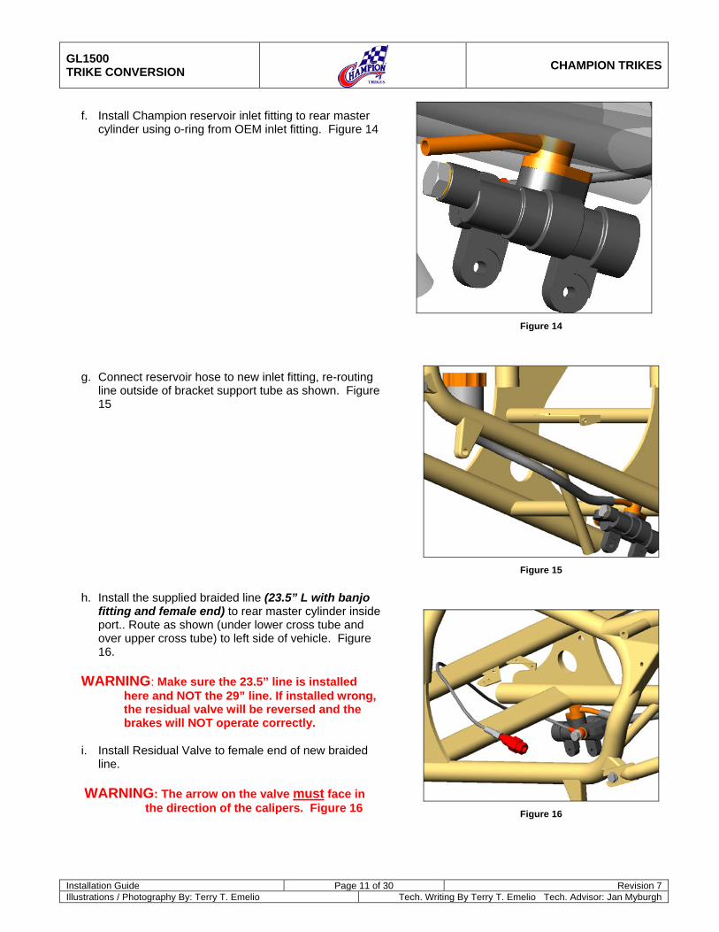
c. Remove banjo bolt and brake line from right front caliper (banjo bolt will not be reused).
d. Reinstall brake line and loose end of braided cross-over line using supplied double banjo bolt and crush washers to right front caliper. Figure 9
e. Release brake lever and bleed front brake system.
Figure 7
Figure 8
Figure 9
CAUTION : Failure to follow these instructions can lead to serious personal injury and/or property damage and may void the warranty
GL1500 TRIKE CONVERSION
CHAMPION TRIKES
Installation Guide Page 10 of 30 Revision 7 Illustrations / Photography By: Terry T. Emelio Tech. Writing By Terry T. Emelio Tech. Advisor: Jan Myburgh
3.5 Modification to Rear Brake System and Frame
a. Remove banjo bolt securing rear brake hard line to rear master cylinder. Bend hard line down and away from rear master cylinder. Figure 10
b. Install supplied M10 bolt and one crush washer to plug the hole that the banjo bolt was just removed from. Figure 10
c. Disconnect and remove the front brake line from the side port of the rear master cylinder, the tabs securing it to the frame and the hard line to the front. Figure 11
d. Bend the two-position tab up as shown. Figure 12
e. Cut off (remove) tab at top center of exhaust collector heat shield. Figure 13
Figure 10
Figure 11
Figure 12
Figure 13
GL1500 TRIKE CONVERSION
CHAMPION TRIKES
Installation Guide Page 11 of 30 Revision 7 Illustrations / Photography By: Terry T. Emelio Tech. Writing By Terry T. Emelio Tech. Advisor: Jan Myburgh
f. Install Champion reservoir inlet fitting to rear master cylinder using o-ring from OEM inlet fitting. Figure 14
g. Connect reservoir hose to new inlet fitting, re-routing line outside of bracket support tube as shown. Figure 15
h. Install the supplied braided line (23.5” L with banjo fitting and female end) to rear master cylinder inside port.. Route as shown (under lower cross tube and over upper cross tube) to left side of vehicle. Figure 16.
WARNING: Make sure the 23.5” line is installed here and NOT the 29” line. If installed wrong, the residual valve will be reversed and the brakes will NOT operate correctly.
i. Install Residual Valve to female end of new braided line.
WARNING: The arrow on the valve must face in the direction of the calipers. Figure 16
Figure 14
Figure 15
Figure 16
GL1500 TRIKE CONVERSION
CHAMPION TRIKES
Installation Guide Page 12 of 30 Revision 7 Illustrations / Photography By: Terry T. Emelio Tech. Writing By Terry T. Emelio Tech. Advisor: Jan Myburgh
4 INSTALL TRIKE CONVERSION KIT
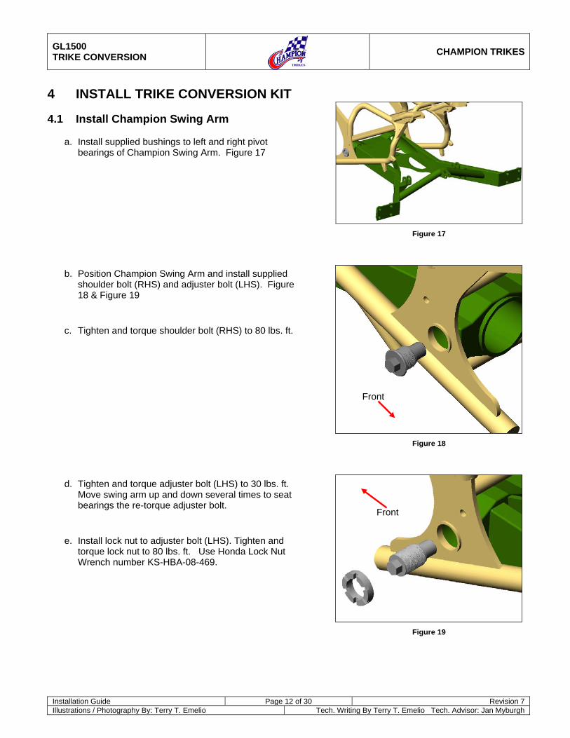
4.1 Install Champion Swing Arm
a. Install supplied bushings to left and right pivot bearings of Champion Swing Arm. Figure 17
b. Position Champion Swing Arm and install supplied shoulder bolt (RHS) and adjuster bolt (LHS). Figure 18 & Figure 19
c. Tighten and torque shoulder bolt (RHS) to 80 lbs. ft.
d. Tighten and torque adjuster bolt (LHS) to 30 lbs. ft. Move swing arm up and down several times to seat bearings the re-torque adjuster bolt.
e. Install lock nut to adjuster bolt (LHS). Tighten and torque lock nut to 80 lbs. ft. Use Honda Lock Nut Wrench number KS-HBA-08-469.
Figure 17
Figure 18
Figure 19
Front
Front
GL1500 TRIKE CONVERSION
CHAMPION TRIKES
Installation Guide Page 13 of 30 Revision 7 Illustrations / Photography By: Terry T. Emelio Tech. Writing By Terry T. Emelio Tech. Advisor: Jan Myburgh
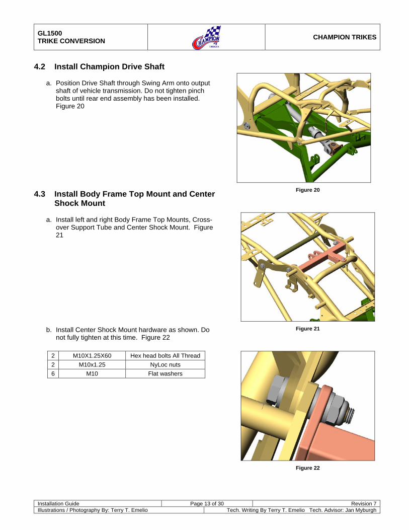
4.2 Install Champion Drive Shaft
a. Position Drive Shaft through Swing Arm onto output shaft of vehicle transmission. Do not tighten pinch bolts until rear end assembly has been installed. Figure 20
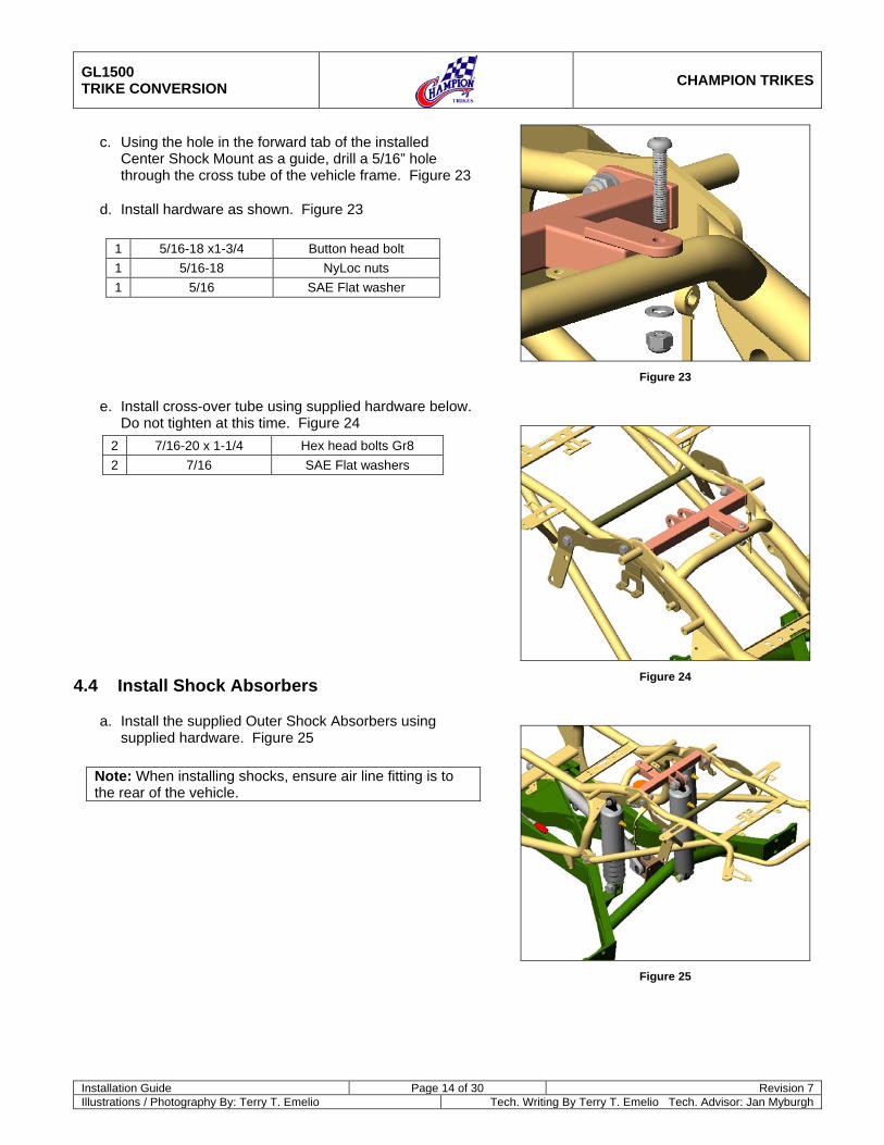
4.3 Install Body Frame Top Mount and Center Shock Mount
a. Install left and right Body Frame Top Mounts, Cross-over Support Tube and Center Shock Mount. Figure 21
b. Install Center Shock Mount hardware as shown. Do not fully tighten at this time. Figure 22
2 M10X1.25X60 Hex head bolts All Thread 2 M10x1.25 NyLoc nuts 6 M10 Flat washers
Figure 20
Figure 21
Figure 22
GL1500 TRIKE CONVERSION
CHAMPION TRIKES
Installation Guide Page 14 of 30 Revision 7 Illustrations / Photography By: Terry T. Emelio Tech. Writing By Terry T. Emelio Tech. Advisor: Jan Myburgh
c. Using the hole in the forward tab of the installed Center Shock Mount as a guide, drill a 5/16” hole through the cross tube of the vehicle frame. Figure 23
d. Install hardware as shown. Figure 23
1 5/16-18 x1-3/4 Button head bolt 1 5/16-18 NyLoc nuts 1 5/16 SAE Flat washer
e. Install cross-over tube using supplied hardware below. Do not tighten at this time. Figure 24
2 7/16-20 x 1-1/4 Hex head bolts Gr8 2 7/16 SAE Flat washers
4.4 Install Shock Absorbers
a. Install the supplied Outer Shock Absorbers using supplied hardware. Figure 25
Note: When installing shocks, ensure air line fitting is to the rear of the vehicle.
Figure 23
Figure 24
Figure 25
GL1500 TRIKE CONVERSION
CHAMPION TRIKES
Installation Guide Page 15 of 30 Revision 7 Illustrations / Photography By: Terry T. Emelio Tech. Writing By Terry T. Emelio Tech. Advisor: Jan Myburgh
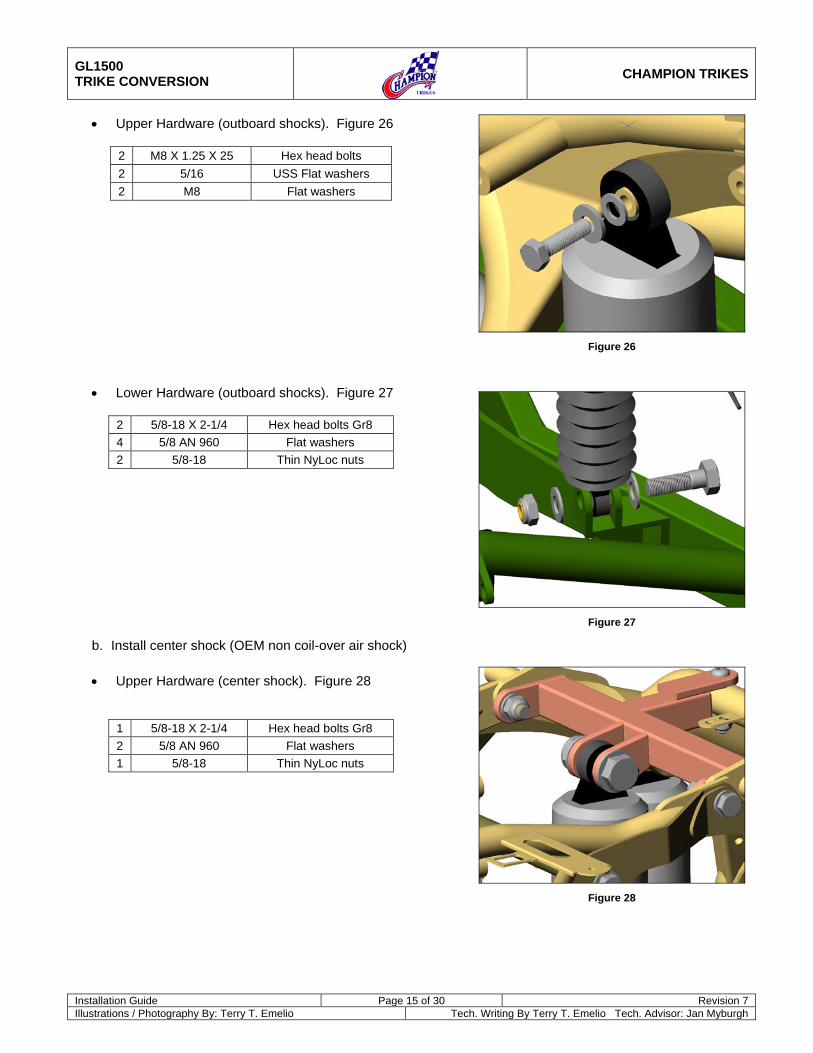
• Upper Hardware (outboard shocks). Figure 26
2 M8 X 1.25 X 25 Hex head bolts 2 5/16 USS Flat washers 2 M8 Flat washers
• Lower Hardware (outboard shocks). Figure 27
2 5/8-18 X 2-1/4 Hex head bolts Gr8 4 5/8 AN 960 Flat washers 2 5/8-18 Thin NyLoc nuts
b. Install center shock (OEM non coil-over air shock)
• Upper Hardware (center shock). Figure 28
1 5/8-18 X 2-1/4 Hex head bolts Gr8 2 5/8 AN 960 Flat washers 1 5/8-18 Thin NyLoc nuts
Figure 26
Figure 27
Figure 28
GL1500 TRIKE CONVERSION
CHAMPION TRIKES
Installation Guide Page 16 of 30 Revision 7 Illustrations / Photography By: Terry T. Emelio Tech. Writing By Terry T. Emelio Tech. Advisor: Jan Myburgh
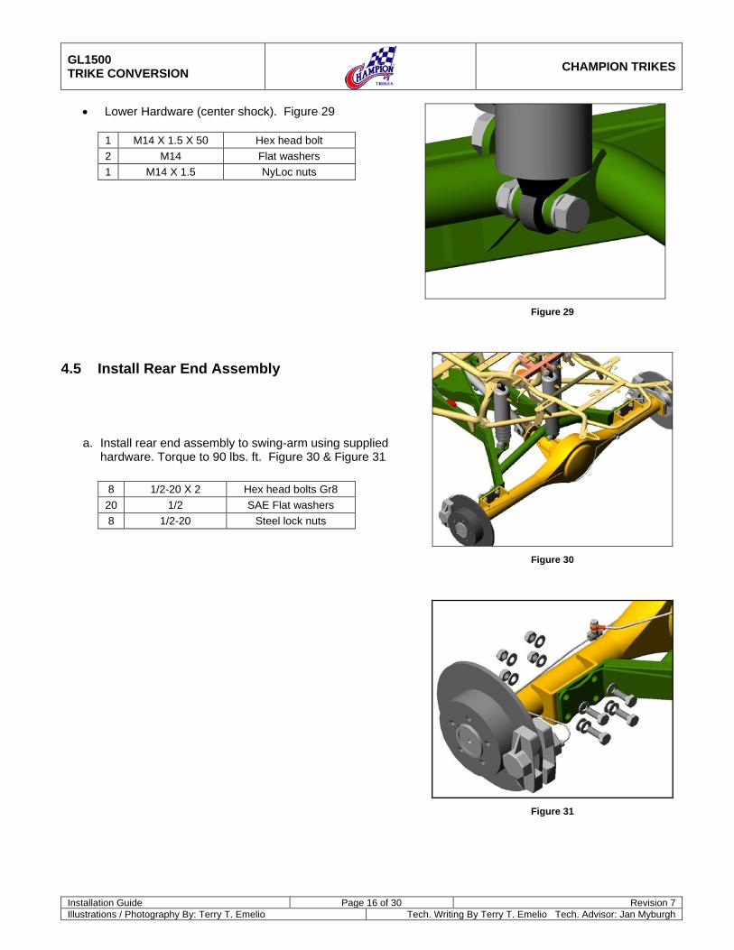
• Lower Hardware (center shock). Figure 29
1 M14 X 1.5 X 50 Hex head bolt 2 M14 Flat washers 1 M14 X 1.5 NyLoc nuts
4.5 Install Rear End Assembly
a. Install rear end assembly to swing-arm using supplied hardware. Torque to 90 lbs. ft. Figure 30 & Figure 31
8 1/2-20 X 2 Hex head bolts Gr8
20 1/2 SAE Flat washers 8 1/2-20 Steel lock nuts
Figure 29
Figure 30
Figure 31
GL1500 TRIKE CONVERSION
CHAMPION TRIKES
Installation Guide Page 17 of 30 Revision 7 Illustrations / Photography By: Terry T. Emelio Tech. Writing By Terry T. Emelio Tech. Advisor: Jan Myburgh
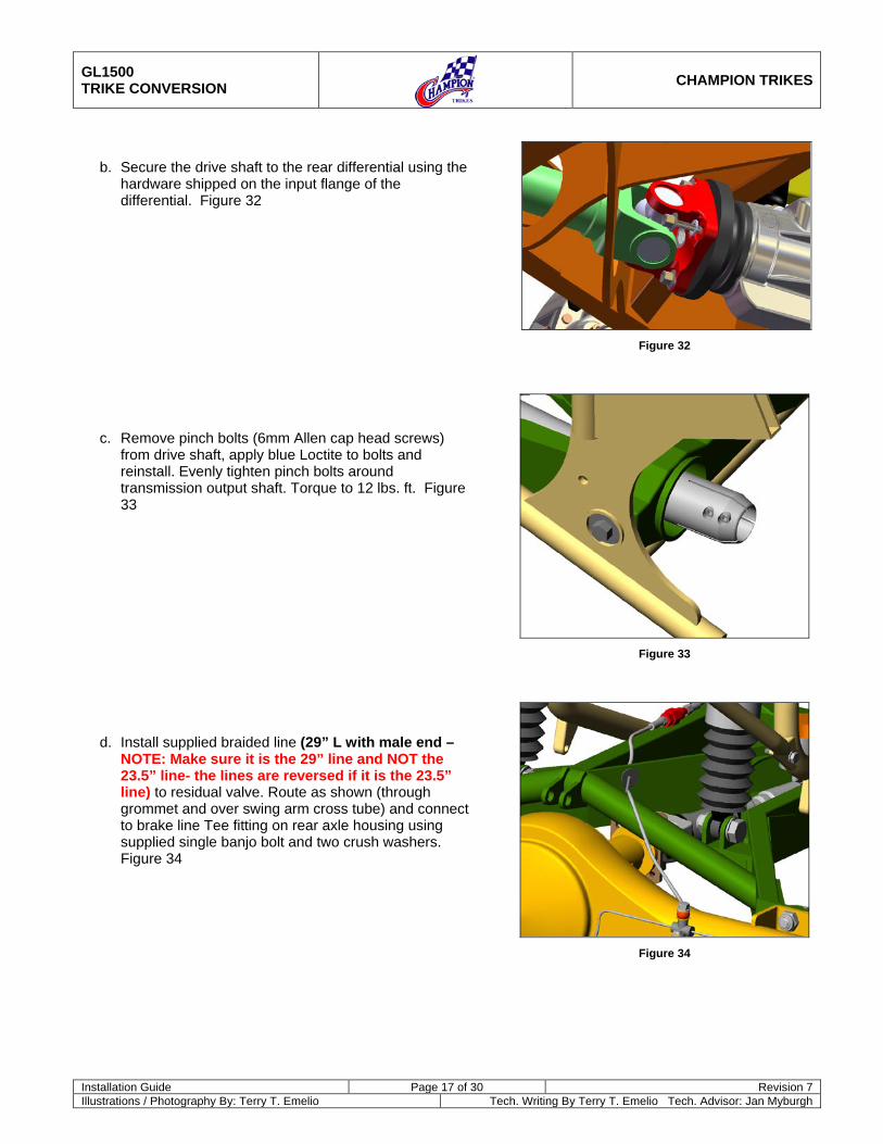
b. Secure the drive shaft to the rear differential using the hardware shipped on the input flange of the differential. Figure 32
c. Remove pinch bolts (6mm Allen cap head screws) from drive shaft, apply blue Loctite to bolts and reinstall. Evenly tighten pinch bolts around transmission output shaft. Torque to 12 lbs. ft. Figure 33
d. Install supplied braided line (29” L with male end – NOTE: Make sure it is the 29” line and NOT the 23.5” line- the lines are reversed if it is the 23.5” line) to residual valve. Route as shown (through grommet and over swing arm cross tube) and connect to brake line Tee fitting on rear axle housing using supplied single banjo bolt and two crush washers. Figure 34
Figure 32
Figure 33
Figure 34
GL1500 TRIKE CONVERSION
CHAMPION TRIKES
Installation Guide Page 18 of 30 Revision 7 Illustrations / Photography By: Terry T. Emelio Tech. Writing By Terry T. Emelio Tech. Advisor: Jan Myburgh
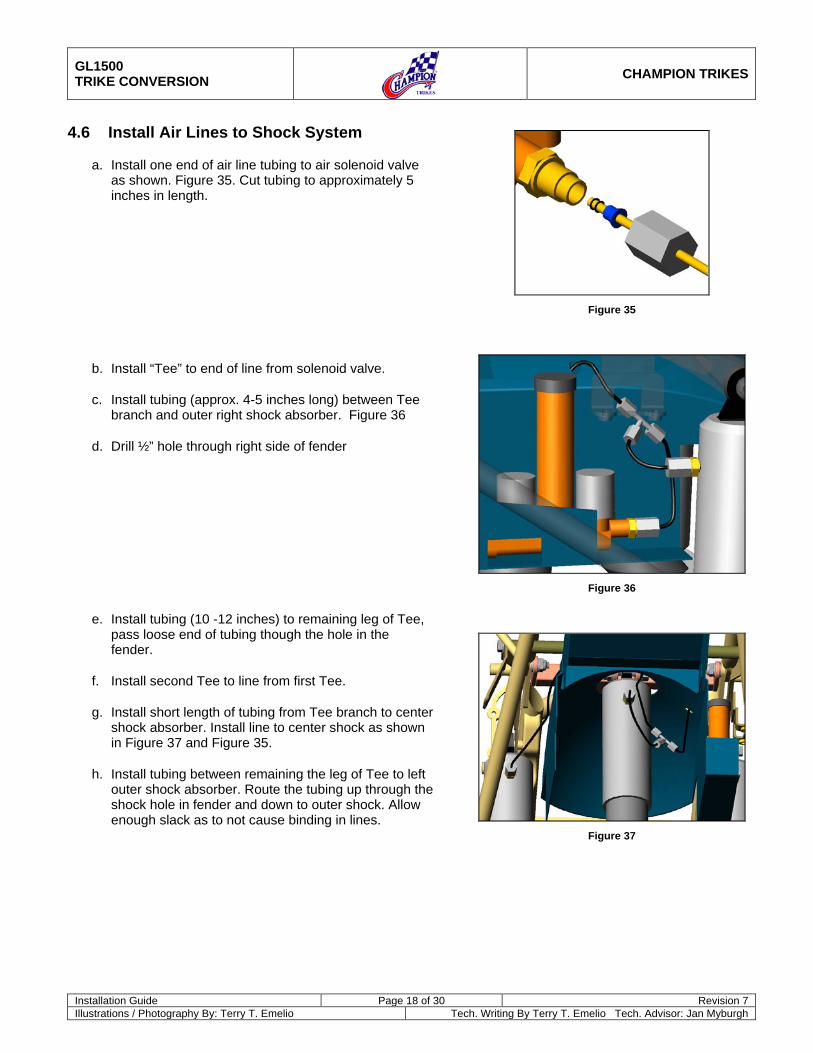
4.6 Install Air Lines to Shock System
a. Install one end of air line tubing to air solenoid valve as shown. Figure 35. Cut tubing to approximately 5 inches in length.
b. Install “Tee” to end of line from solenoid valve.
c. Install tubing (approx. 4-5 inches long) between Tee branch and outer right shock absorber. Figure 36
d. Drill ½” hole through right side of fender
e. Install tubing (10 -12 inches) to remaining leg of Tee, pass loose end of tubing though the hole in the fender.
f. Install second Tee to line from first Tee.
g. Install short length of tubing from Tee branch to center shock absorber. Install line to center shock as shown in Figure 37 and Figure 35.
h. Install tubing between remaining the leg of Tee to left outer shock absorber. Route the tubing up through the shock hole in fender and down to outer shock. Allow enough slack as to not cause binding in lines.
Figure 35
Figure 36
Figure 37
GL1500 TRIKE CONVERSION
CHAMPION TRIKES
Installation Guide Page 19 of 30 Revision 7 Illustrations / Photography By: Terry T. Emelio Tech. Writing By Terry T. Emelio Tech. Advisor: Jan Myburgh
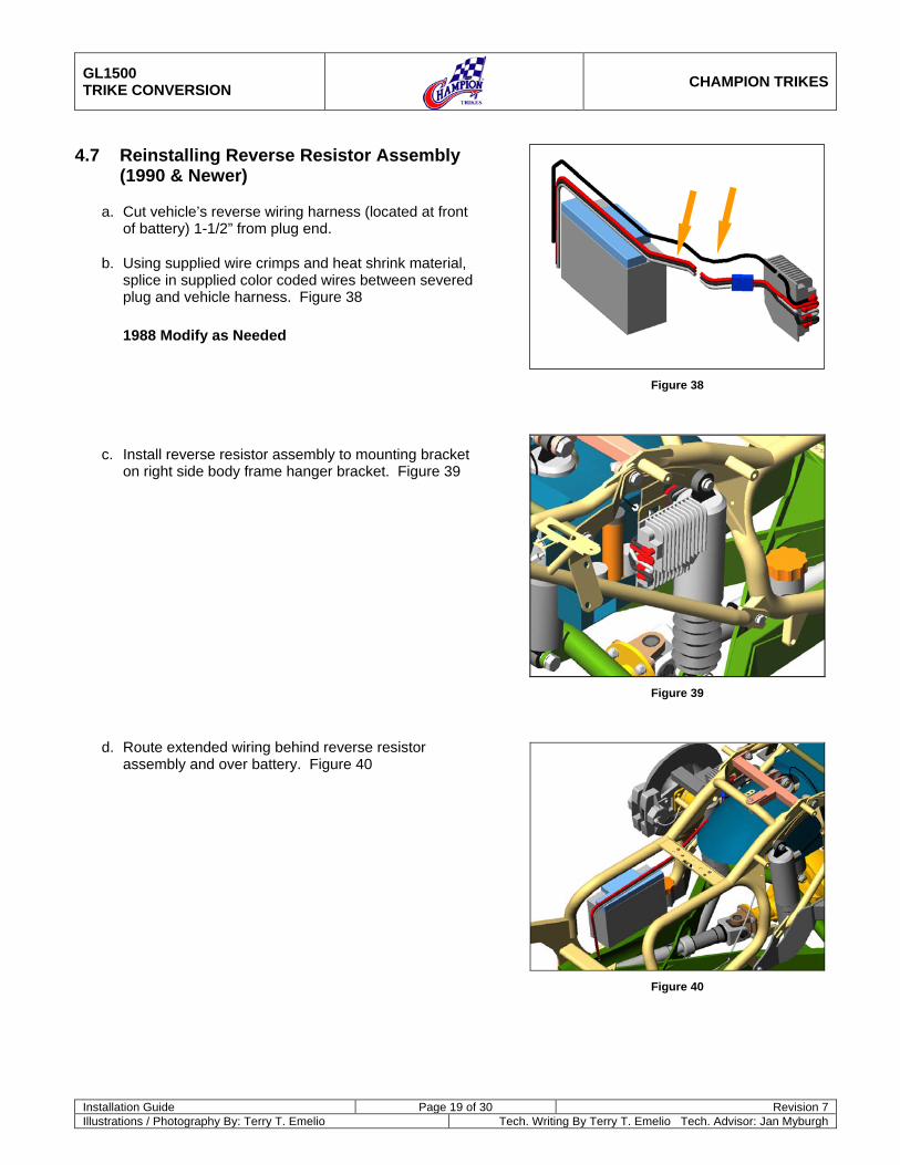
4.7 Reinstalling Reverse Resistor Assembly (1990 & Newer)
a. Cut vehicle’s reverse wiring harness (located at front of battery) 1-1/2” from plug end.
b. Using supplied wire crimps and heat shrink material, splice in supplied color coded wires between severed plug and vehicle harness. Figure 38
1988 Modify as Needed
c. Install reverse resistor assembly to mounting bracket on right side body frame hanger bracket. Figure 39
d. Route extended wiring behind reverse resistor assembly and over battery. Figure 40
Figure 38
Figure 39
Figure 40
GL1500 TRIKE CONVERSION
CHAMPION TRIKES
Installation Guide Page 20 of 30 Revision 7 Illustrations / Photography By: Terry T. Emelio Tech. Writing By Terry T. Emelio Tech. Advisor: Jan Myburgh
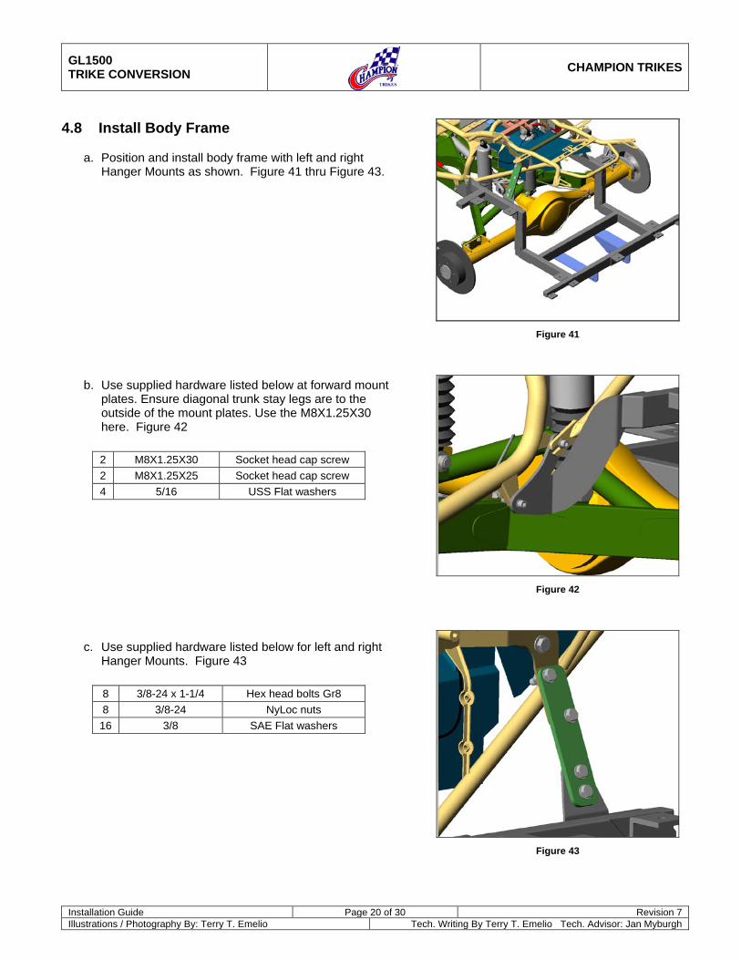
4.8 Install Body Frame
a. Position and install body frame with left and right Hanger Mounts as shown. Figure 41 thru Figure 43.
b. Use supplied hardware listed below at forward mount plates. Ensure diagonal trunk stay legs are to the outside of the mount plates. Use the M8X1.25X30 here. Figure 42
2 M8X1.25X30 Socket head cap screw 2 M8X1.25X25 Socket head cap screw 4 5/16 USS Flat washers
c. Use supplied hardware listed below for left and right Hanger Mounts. Figure 43
8 3/8-24 x 1-1/4 Hex head bolts Gr8 8 3/8-24 NyLoc nuts
16 3/8 SAE Flat washers
Figure 41
Figure 42
Figure 43
GL1500 TRIKE CONVERSION
CHAMPION TRIKES
Installation Guide Page 21 of 30 Revision 7 Illustrations / Photography By: Terry T. Emelio Tech. Writing By Terry T. Emelio Tech. Advisor: Jan Myburgh
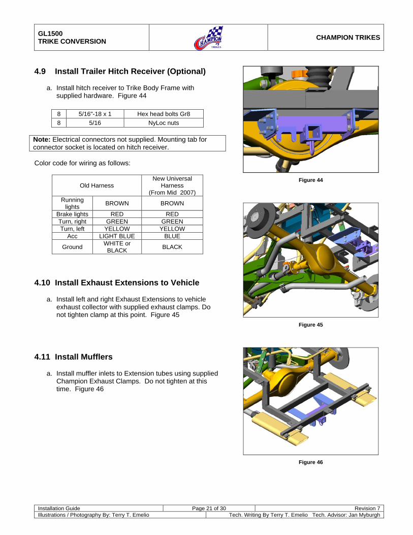
4.9 Install Trailer Hitch Receiver (Optional)
a. Install hitch receiver to Trike Body Frame with supplied hardware. Figure 44
8 5/16"-18 x 1 Hex head bolts Gr8 8 5/16 NyLoc nuts
Note: Electrical connectors not supplied. Mounting tab for connector socket is located on hitch receiver. Color code for wiring as follows:
Old Harness New Universal
Harness (From Mid 2007)
Running lights BROWN BROWN
Brake lights RED RED Turn, right GREEN GREEN Turn, left YELLOW YELLOW
Acc LIGHT BLUE BLUE
Ground WHITE or BLACK BLACK
4.10 Install Exhaust Extensions to Vehicle
a. Install left and right Exhaust Extensions to vehicle exhaust collector with supplied exhaust clamps. Do not tighten clamp at this point. Figure 45
4.11 Install Mufflers
a. Install muffler inlets to Extension tubes using supplied Champion Exhaust Clamps. Do not tighten at this time. Figure 46
Figure 44
Figure 45
Figure 46
GL1500 TRIKE CONVERSION
CHAMPION TRIKES
Installation Guide Page 22 of 30 Revision 7 Illustrations / Photography By: Terry T. Emelio Tech. Writing By Terry T. Emelio Tech. Advisor: Jan Myburgh
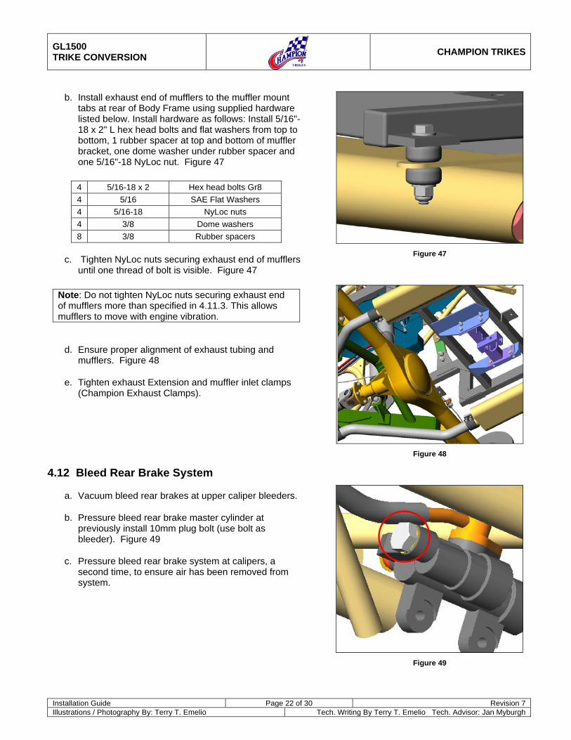
b. Install exhaust end of mufflers to the muffler mount tabs at rear of Body Frame using supplied hardware listed below. Install hardware as follows: Install 5/16"-18 x 2" L hex head bolts and flat washers from top to bottom, 1 rubber spacer at top and bottom of muffler bracket, one dome washer under rubber spacer and one 5/16"-18 NyLoc nut. Figure 47
4 5/16-18 x 2 Hex head bolts Gr8 4 5/16 SAE Flat Washers 4 5/16-18 NyLoc nuts 4 3/8 Dome washers 8 3/8 Rubber spacers
c. Tighten NyLoc nuts securing exhaust end of mufflers until one thread of bolt is visible. Figure 47
Note: Do not tighten NyLoc nuts securing exhaust end of mufflers more than specified in 4.11.3. This allows mufflers to move with engine vibration.
d. Ensure proper alignment of exhaust tubing and mufflers. Figure 48
e. Tighten exhaust Extension and muffler inlet clamps (Champion Exhaust Clamps).
4.12 Bleed Rear Brake System
a. Vacuum bleed rear brakes at upper caliper bleeders.
b. Pressure bleed rear brake master cylinder at previously install 10mm plug bolt (use bolt as bleeder). Figure 49
c. Pressure bleed rear brake system at calipers, a second time, to ensure air has been removed from system.
Figure 47
Figure 48
Figure 49
GL1500 TRIKE CONVERSION
CHAMPION TRIKES
Installation Guide Page 23 of 30 Revision 7 Illustrations / Photography By: Terry T. Emelio Tech. Writing By Terry T. Emelio Tech. Advisor: Jan Myburgh
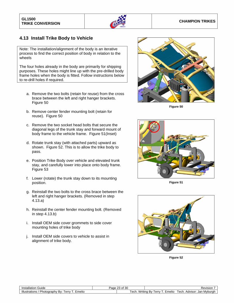
4.13 Install Trike Body to Vehicle Note: The installation/alignment of the body is an iterative process to find the correct position of body in relation to the wheels The four holes already in the body are primarily for shipping purposes. These holes might line up with the pre-drilled body frame holes when the body is fitted. Follow instructions below to re-drill holes if required.
a. Remove the two bolts (retain for reuse) from the cross brace between the left and right hanger brackets. Figure 50
b. Remove center fender mounting bolt (retain for reuse). Figure 50
c. Remove the two socket head bolts that secure the diagonal legs of the trunk stay and forward mount of body frame to the vehicle frame. Figure 51(Inset)
d. Rotate trunk stay (with attached parts) upward as shown. Figure 52. This is to allow the trike body to pass.
e. Position Trike Body over vehicle and elevated trunk stay, and carefully lower into place onto body frame. Figure 53
f. Lower (rotate) the trunk stay down to its mounting position.
g. Reinstall the two bolts to the cross brace between the left and right hanger brackets. (Removed in step 4.13.a)
h. Reinstall the center fender mounting bolt. (Removed in step 4.13.b)
i. Install OEM side cover grommets to side cover mounting holes of trike body
j. Install OEM side covers to vehicle to assist in alignment of trike body.
Figure 50
Figure 51
Figure 52
GL1500 TRIKE CONVERSION
CHAMPION TRIKES
Installation Guide Page 24 of 30 Revision 7 Illustrations / Photography By: Terry T. Emelio Tech. Writing By Terry T. Emelio Tech. Advisor: Jan Myburgh
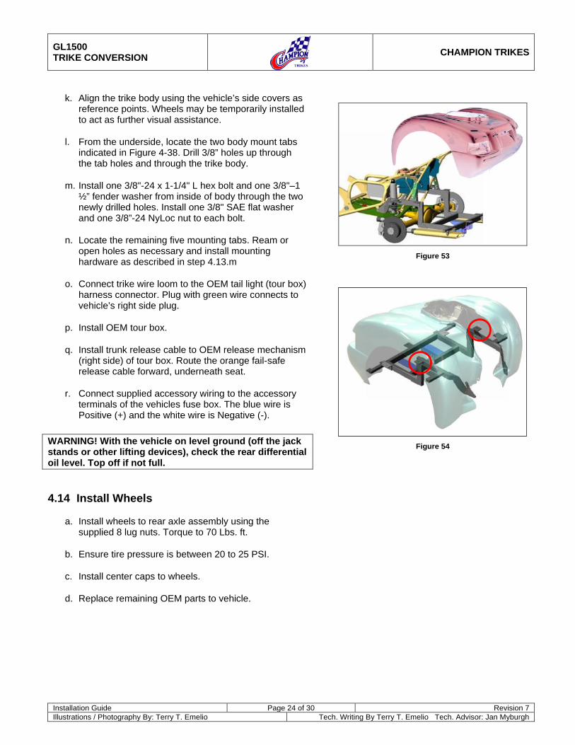
k. Align the trike body using the vehicle’s side covers as reference points. Wheels may be temporarily installed to act as further visual assistance.
l. From the underside, locate the two body mount tabs indicated in Figure 4-38. Drill 3/8” holes up through the tab holes and through the trike body.
m. Install one 3/8"-24 x 1-1/4" L hex bolt and one 3/8"–1 ½” fender washer from inside of body through the two newly drilled holes. Install one 3/8" SAE flat washer and one 3/8”-24 NyLoc nut to each bolt.
n. Locate the remaining five mounting tabs. Ream or open holes as necessary and install mounting hardware as described in step 4.13.m
o. Connect trike wire loom to the OEM tail light (tour box) harness connector. Plug with green wire connects to vehicle’s right side plug.
p. Install OEM tour box.
q. Install trunk release cable to OEM release mechanism (right side) of tour box. Route the orange fail-safe release cable forward, underneath seat.
r. Connect supplied accessory wiring to the accessory terminals of the vehicles fuse box. The blue wire is Positive (+) and the white wire is Negative (-).
WARNING! With the vehicle on level ground (off the jack stands or other lifting devices), check the rear differential oil level. Top off if not full.
4.14 Install Wheels
a. Install wheels to rear axle assembly using the supplied 8 lug nuts. Torque to 70 Lbs. ft.
b. Ensure tire pressure is between 20 to 25 PSI.
c. Install center caps to wheels.
d. Replace remaining OEM parts to vehicle.
Figure 53
Figure 54
GL1500 TRIKE CONVERSION
CHAMPION TRIKES
Installation Guide Page 25 of 30 Revision 7 Illustrations / Photography By: Terry T. Emelio Tech. Writing By Terry T. Emelio Tech. Advisor: Jan Myburgh
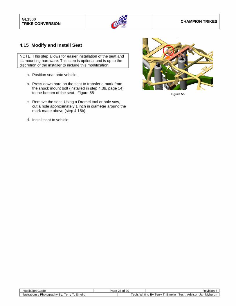
4.15 Modify and Install Seat NOTE: This step allows for easier installation of the seat and its mounting hardware. This step is optional and is up to the discretion of the installer to include this modification.
a. Position seat onto vehicle.
b. Press down hard on the seat to transfer a mark from the shock mount bolt (installed in step 4.3b, page 14) to the bottom of the seat. Figure 55
c. Remove the seat. Using a Dremel tool or hole saw, cut a hole approximately 1 inch in diameter around the mark made above (step 4.15b).
d. Install seat to vehicle.
Figure 55
GL1500 TRIKE CONVERSION
CHAMPION TRIKES
Installation Guide Page 26 of 30 Revision 7 Illustrations / Photography By: Terry T. Emelio Tech. Writing By Terry T. Emelio Tech. Advisor: Jan Myburgh
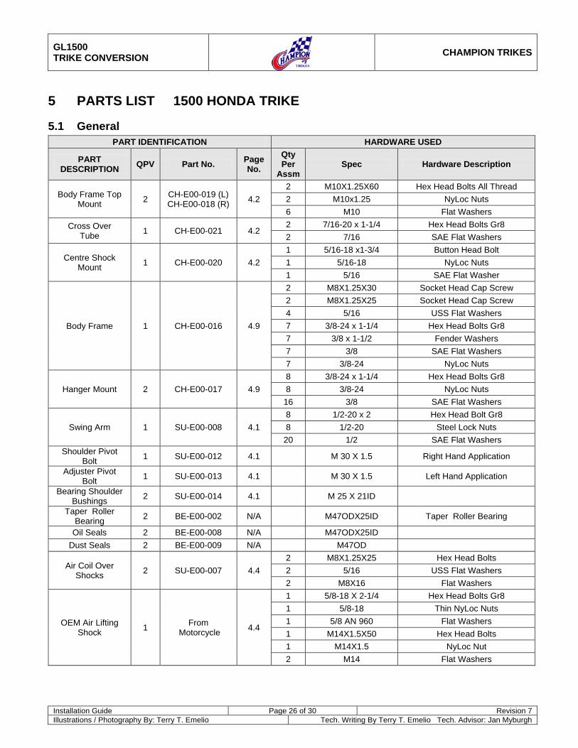
5 PARTS LIST 1500 HONDA TRIKE
5.1 General PART IDENTIFICATION HARDWARE USED
PART DESCRIPTION QPV Part No. Page
No. Qty Per
Assm Spec Hardware Description
Body Frame Top Mount 2 CH-E00-019 (L)
CH-E00-018 (R) 4.2 2 M10X1.25X60 Hex Head Bolts All Thread 2 M10x1.25 NyLoc Nuts 6 M10 Flat Washers
Cross Over Tube 1 CH-E00-021 4.2
2 7/16-20 x 1-1/4 Hex Head Bolts Gr8 2 7/16 SAE Flat Washers
Centre Shock Mount 1 CH-E00-020 4.2
1 5/16-18 x1-3/4 Button Head Bolt 1 5/16-18 NyLoc Nuts 1 5/16 SAE Flat Washer
Body Frame 1 CH-E00-016 4.9
2 M8X1.25X30 Socket Head Cap Screw 2 M8X1.25X25 Socket Head Cap Screw 4 5/16 USS Flat Washers 7 3/8-24 x 1-1/4 Hex Head Bolts Gr8 7 3/8 x 1-1/2 Fender Washers 7 3/8 SAE Flat Washers 7 3/8-24 NyLoc Nuts
Hanger Mount 2 CH-E00-017 4.9 8 3/8-24 x 1-1/4 Hex Head Bolts Gr8 8 3/8-24 NyLoc Nuts
16 3/8 SAE Flat Washers
Swing Arm 1 SU-E00-008 4.1 8 1/2-20 x 2 Hex Head Bolt Gr8 8 1/2-20 Steel Lock Nuts
20 1/2 SAE Flat Washers Shoulder Pivot
Bolt 1 SU-E00-012 4.1 M 30 X 1.5 Right Hand Application
Adjuster Pivot Bolt 1 SU-E00-013 4.1 M 30 X 1.5 Left Hand Application
Bearing Shoulder Bushings 2 SU-E00-014 4.1 M 25 X 21ID
Taper Roller Bearing 2 BE-E00-002 N/A M47ODX25ID Taper Roller Bearing
Oil Seals 2 BE-E00-008 N/A M47ODX25ID Dust Seals 2 BE-E00-009 N/A M47OD
Air Coil Over Shocks 2 SU-E00-007 4.4
2 M8X1.25X25 Hex Head Bolts 2 5/16 USS Flat Washers 2 M8X16 Flat Washers
OEM Air Lifting Shock 1 From
Motorcycle 4.4
1 5/8-18 X 2-1/4 Hex Head Bolts Gr8 1 5/8-18 Thin NyLoc Nuts 1 5/8 AN 960 Flat Washers 1 M14X1.5X50 Hex Head Bolts 1 M14X1.5 NyLoc Nut 2 M14 Flat Washers
GL1500 TRIKE CONVERSION
CHAMPION TRIKES
Installation Guide Page 27 of 30 Revision 7 Illustrations / Photography By: Terry T. Emelio Tech. Writing By Terry T. Emelio Tech. Advisor: Jan Myburgh
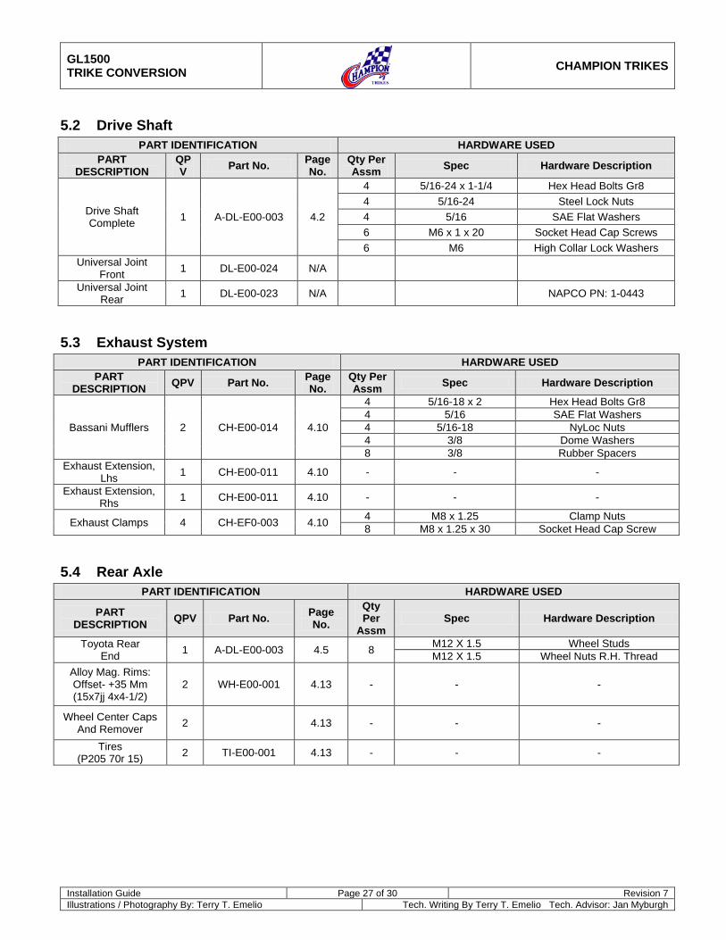
5.2 Drive Shaft PART IDENTIFICATION HARDWARE USED
PART DESCRIPTION
QPV Part No. Page
No. Qty Per Assm Spec Hardware Description
Drive Shaft Complete 1 A-DL-E00-003 4.2
4 5/16-24 x 1-1/4 Hex Head Bolts Gr8 4 5/16-24 Steel Lock Nuts 4 5/16 SAE Flat Washers 6 M6 x 1 x 20 Socket Head Cap Screws 6 M6 High Collar Lock Washers
Universal Joint Front 1 DL-E00-024 N/A
Universal Joint Rear 1 DL-E00-023 N/A NAPCO PN: 1-0443
5.3 Exhaust System PART IDENTIFICATION HARDWARE USED
PART DESCRIPTION QPV Part No. Page
No. Qty Per Assm Spec Hardware Description
Bassani Mufflers 2 CH-E00-014 4.10
4 5/16-18 x 2 Hex Head Bolts Gr8 4 5/16 SAE Flat Washers 4 5/16-18 NyLoc Nuts 4 3/8 Dome Washers 8 3/8 Rubber Spacers
Exhaust Extension, Lhs 1 CH-E00-011 4.10 - - -
Exhaust Extension, Rhs 1 CH-E00-011 4.10 - - -
Exhaust Clamps 4 CH-EF0-003 4.10 4 M8 x 1.25 Clamp Nuts 8 M8 x 1.25 x 30 Socket Head Cap Screw
5.4 Rear Axle PART IDENTIFICATION HARDWARE USED
PART DESCRIPTION QPV Part No. Page
No. Qty Per
Assm Spec Hardware Description
Toyota Rear End 1 A-DL-E00-003 4.5 8 M12 X 1.5 Wheel Studs
M12 X 1.5 Wheel Nuts R.H. Thread Alloy Mag. Rims: Offset- +35 Mm (15x7jj 4x4-1/2)
2 WH-E00-001 4.13 - - -
Wheel Center Caps And Remover 2 4.13 - - -
Tires (P205 70r 15) 2 TI-E00-001 4.13 - - -
GL1500 TRIKE CONVERSION
CHAMPION TRIKES
Installation Guide Page 28 of 30 Revision 7 Illustrations / Photography By: Terry T. Emelio Tech. Writing By Terry T. Emelio Tech. Advisor: Jan Myburgh
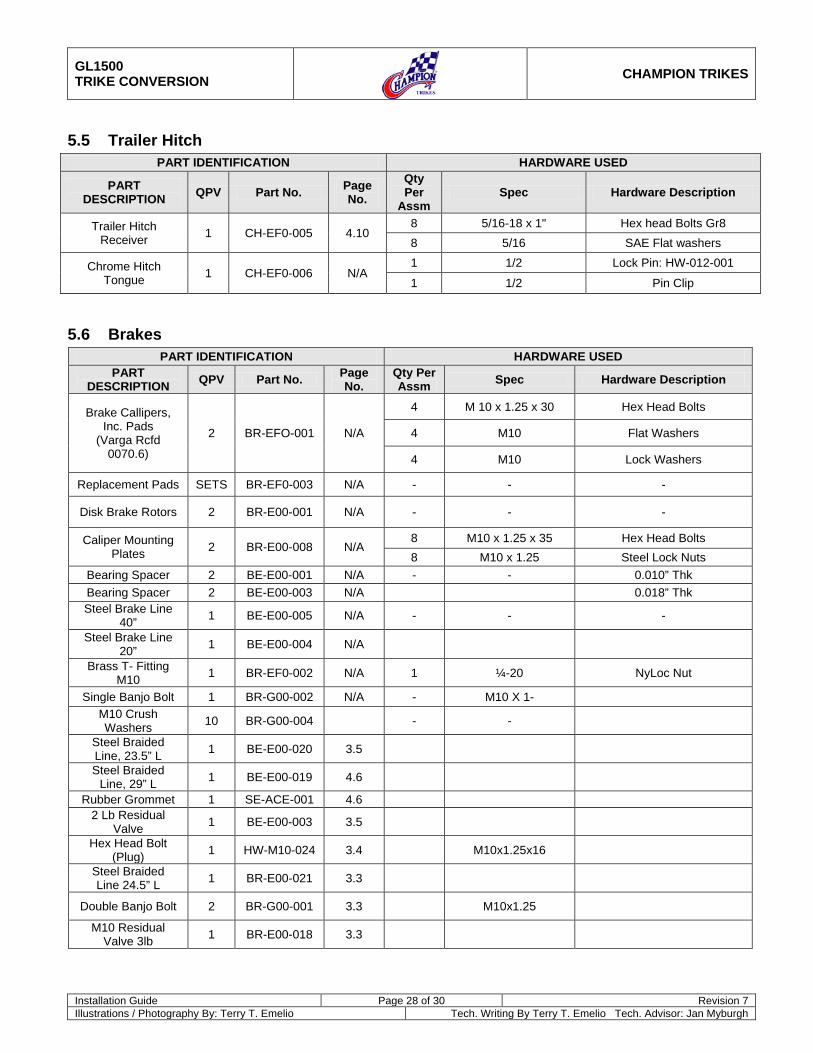
5.5 Trailer Hitch PART IDENTIFICATION HARDWARE USED
PART DESCRIPTION QPV Part No. Page
No. Qty Per
Assm Spec Hardware Description
Trailer Hitch Receiver 1 CH-EF0-005 4.10
8 5/16-18 x 1" Hex head Bolts Gr8 8 5/16 SAE Flat washers
Chrome Hitch Tongue 1 CH-EF0-006 N/A
1 1/2 Lock Pin: HW-012-001
1 1/2 Pin Clip
5.6 Brakes PART IDENTIFICATION HARDWARE USED
PART DESCRIPTION QPV Part No. Page
No. Qty Per Assm Spec Hardware Description
Brake Callipers, Inc. Pads
(Varga Rcfd 0070.6)
2 BR-EFO-001 N/A
4 M 10 x 1.25 x 30 Hex Head Bolts
4 M10 Flat Washers
4 M10 Lock Washers
Replacement Pads SETS BR-EF0-003 N/A - - -
Disk Brake Rotors 2 BR-E00-001 N/A - - -
Caliper Mounting Plates 2 BR-E00-008 N/A
8 M10 x 1.25 x 35 Hex Head Bolts 8 M10 x 1.25 Steel Lock Nuts
Bearing Spacer 2 BE-E00-001 N/A - - 0.010” Thk Bearing Spacer 2 BE-E00-003 N/A 0.018” Thk Steel Brake Line
40” 1 BE-E00-005 N/A - - -
Steel Brake Line 20” 1 BE-E00-004 N/A
Brass T- Fitting M10 1 BR-EF0-002 N/A 1 ¼-20 NyLoc Nut
Single Banjo Bolt 1 BR-G00-002 N/A - M10 X 1- M10 Crush Washers 10 BR-G00-004 - -
Steel Braided Line, 23.5” L 1 BE-E00-020 3.5
Steel Braided Line, 29” L 1 BE-E00-019 4.6
Rubber Grommet 1 SE-ACE-001 4.6 2 Lb Residual
Valve 1 BE-E00-003 3.5
Hex Head Bolt (Plug) 1 HW-M10-024 3.4 M10x1.25x16
Steel Braided Line 24.5” L 1 BR-E00-021 3.3
Double Banjo Bolt 2 BR-G00-001 3.3 M10x1.25
M10 Residual Valve 3lb 1 BR-E00-018 3.3
GL1500 TRIKE CONVERSION
CHAMPION TRIKES
Installation Guide Page 29 of 30 Revision 7 Illustrations / Photography By: Terry T. Emelio Tech. Writing By Terry T. Emelio Tech. Advisor: Jan Myburgh
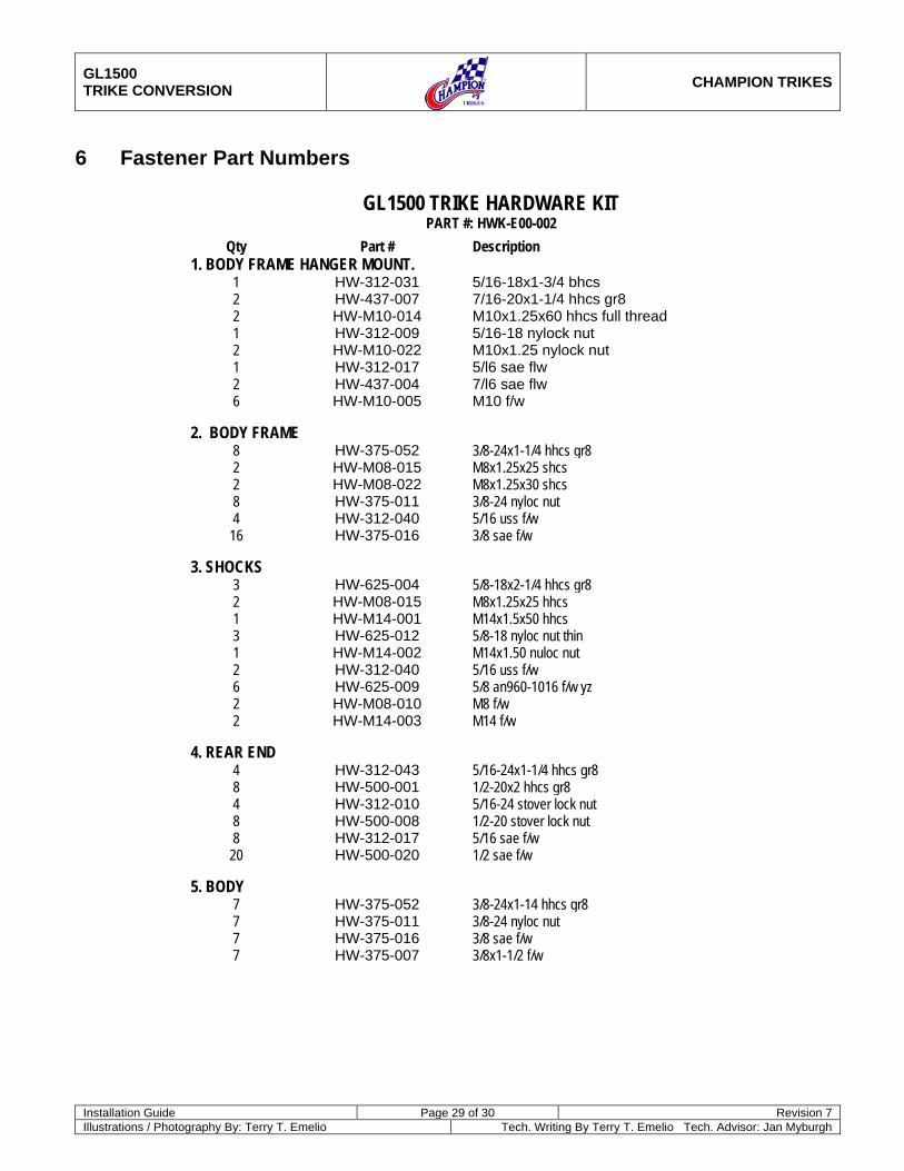
6 Fastener Part Numbers
GL1500 TRIKE HARDWARE KIT PART #: HWK-E00-002
Qty Part # Description 1. BODY FRAME HANGER MOUNT.
1 HW-312-031 5/16-18x1-3/4 bhcs 2 HW-437-007 7/16-20x1-1/4 hhcs gr8 2 HW-M10-014 M10x1.25x60 hhcs full thread 1 HW-312-009 5/16-18 nylock nut 2 HW-M10-022 M10x1.25 nylock nut 1 HW-312-017 5/l6 sae flw 2 HW-437-004 7/l6 sae flw 6 HW-M10-005 M10 f/w
2. BODY FRAME 8 HW-375-052 3/8-24x1-1/4 hhcs gr8 2 HW-M08-015 M8x1.25x25 shcs 2 HW-M08-022 M8x1.25x30 shcs 8 HW-375-011 3/8-24 nyloc nut 4 HW-312-040 5/16 uss f/w 16 HW-375-016 3/8 sae f/w
3. SHOCKS
3 HW-625-004 5/8-18x2-1/4 hhcs gr8 2 HW-M08-015 M8x1.25x25 hhcs 1 HW-M14-001 M14x1.5x50 hhcs 3 HW-625-012 5/8-18 nyloc nut thin 1 HW-M14-002 M14x1.50 nuloc nut 2 HW-312-040 5/16 uss f/w 6 HW-625-009 5/8 an960-1016 f/w yz 2 HW-M08-010 M8 f/w 2 HW-M14-003 M14 f/w
4. REAR END 4 HW-312-043 5/16-24x1-1/4 hhcs gr8 8 HW-500-001 1/2-20x2 hhcs gr8 4 HW-312-010 5/16-24 stover lock nut 8 HW-500-008 1/2-20 stover lock nut 8 HW-312-017 5/16 sae f/w 20 HW-500-020 1/2 sae f/w
5. BODY
7 HW-375-052 3/8-24x1-14 hhcs gr8 7 HW-375-011 3/8-24 nyloc nut 7 HW-375-016 3/8 sae f/w 7 HW-375-007 3/8x1-1/2 f/w
GL1500 TRIKE CONVERSION
CHAMPION TRIKES
Installation Guide Page 30 of 30 Revision 7 Illustrations / Photography By: Terry T. Emelio Tech. Writing By Terry T. Emelio Tech. Advisor: Jan Myburgh
7 Fender Template