Honda Element Seattle From Klein Honda Your Renton Area Honda Dealer- New Honda Element Seattle
HONDACRF250X
OWNER’S MANUAL &COMPETITION HANDBOOK
IMPORTANT NOTICES
This manual should be considered a permanent part of the motorcycle and should remain with the motorcycle when it is resold.
All information in this publication is based on the latest product information available at the time of approval for printing. Honda Motor Co., Ltd.reserves the right to make changes at any time without notice and without incurring any obligation.
No part of this publication may be reproduced without written permission.
C Honda Motor Co., Ltd., 2004
FOR RECREATIONAL OFF-ROAD OR COMPETITION USE ONLYThis motorcycle is designed and manufactured for recreational off-road use or competition only and is coveredby noise control warranty. It does not conform to federal motor vehicle safety standards and operation onpublic streets, roads, or highways is illegal. If you need to cross a paved or public road, get off and walk yourmotorcycle across.
Do not modify any emission-related items except for competition use. Any emission-relaed modificationsshould be restored to standard factory specifications before resuming recreational off-road use.
NO PASSENGERSThis motorcycle is designed and constructed as an operator-only model. The motorcycle load limit and seatingconfiguration do not safety permit the carrying of a passenger.
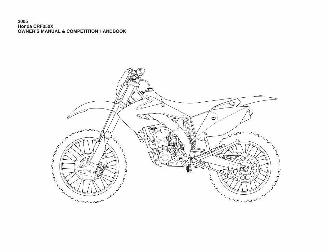
2005Honda CRF250XOWNER’S MANUAL & COMPETITION HANDBOOK
IntroductionCongratulations on choosing your Honda off-road motorcycle.
When you own a Honda, you’re part of a worldwide family of satisfied customers-peoplewho appreciate Honda’s reputation for buildingquality into every product.
Your Honda was designed as a recreationalmotorcycle for off-road use by one rider only.
Before riding, take time to get acquainted withyour motorcycle and how it works. To protectyour investment, we urge you to take responsibility for keeping your motorcycle wellmaintained. Scheduled service is a must, ofcourse. But it’s just as important to observe thebreak-in guidelines, and perform all the pre-rideand other periodic checks detailed in this manual.
We also recommend that you read the owner’smanual before you ride. It’s full of facts, instructions, safety information, and helpful tips.To make it easy to use, the manual contains a table of contents, a detailed list of topics at the beginning of each section, and anindex at the back of the book.
As you read this manual, you will find information that is preceded by a symbol. This information is intended to help youavoid damage to your Honda, other property, orthe environment.
Unless you are mechanically qualified and havethe proper tools, you should see your Hondadealer for the service and adjustment proceduresdiscussed in this manual.
NOTICE
The official Honda Service Manual for yourmotorcycle is available (page 164). It is thesame manual your dealer uses. If you plan to doany service on your motorcycle beyond thestandard maintenance procedures in this manual,you will find the Service Manual a valuablereference.
Your new Honda is covered by Noise ControlWarranty (USA only).
There are responsibilities, restrictions, andexclusions which apply to this warranty. Pleaseread the Honda Motorcycle Warranties Bookletgiven to you by your Honda dealer at the line ofpurchase. Be sure to keep your Honda owner’scard (USA only) with your Warranties Booklet.
It is important to realize that your warranty foryour Honda applies to defects in material orfactory workmanship. Your warranty coveragedoes not apply to normal wear or deteriorationassociated with using the motorcycle.
Your warranty coverage will not be voided if youchoose to perform your own maintenance.However, you should have the proper tools andservice information and be mechanicallyqualified. Failures that occur due directly toimproper maintenance or lack of maintenance arenot covered.
This motorcycle has no cooling fan. For thisreason, engine overheating and coolant loss willoccur if the engine is kept idling too long whenhot. Additionally, when riding in mud or sand, orany condition that causes high engine load at lowvehicle speed, the time it takes for the engine tooverheat will be shortened, especially when theambient temperature is high. Continuing tooperate the unit in these conditions will result inengine damage.
An optional cooling fan is available and isrecommended for units that will be operated inconditions with high engine load and low vehiclespeed.
Whenever you ride, tread lightly. By staying onestablished trails and riding only in approvedareas, you help protect the environment and keepoff-road riding areas open for the future.
If you have any questions, or if you ever need aspecial service or repairs, remember that yourHonda dealer knows your motorcycle best and isdedicated to your complete satisfaction.
Please report any change of address or ownershipto your Honda dealer so we will be able to contact you concerning important productioninformation.
You may also want to visit our website at www.honda.com
Happy riding!
Introduction
A Few Words About SafetyYour safety, and the safety of others, is very important. And operating this motorcycle safely is an important responsibility.
To help you make informed decisions about safety, we have provided operating procedures and other information on labels and in this manual. This information alerts you to potential hazards that could hurt you or others.
Of course, it is not practical or possible to warn you about all hazards associated with operating or maintaining a motorcycle. You must use your own goodjudgment.
You will find important safety information in a variety of forms, including:
• Safety Labels –– on the motorcycle.
• Safety Messages –– preceded by a safety alert symbol and one of three signal words: DANGER, WARNING, or CAUTION.
These signal words mean:
You WILL be KILLED or SERIOUSLY HURT if you don’t follow instructions.
You CAN be KILLED or SERIOUSLY HURT if you don’t follow instructions.
You CAN be HURT if you don’t follow instructions.
• Safety Headings –– such as Important Safety Reminders or Important Safety Precautions.
• Safety Section –– such as Motorcycle Safety.
• Instructions –– how to use this motorcycle correctly and safety.
This entire book is filled with important safety information–– please read it carefully.
Safety Messages
DANGER
WARNING
CAUTION
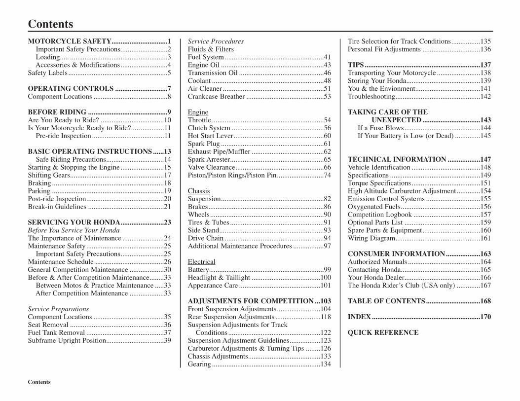
ContentsMOTORCYCLE SAFETY...............................1
Important Safety Precautions..........................2Loading..... ......................................................3Accessories & Modifications..........................4
Safety Labels .......................................................5
OPERATING CONTROLS .............................7Component Locations .........................................8
BEFORE RIDING ............................................9Are You Ready to Ride? ...................................10Is Your Motorcycle Ready to Ride?..... .............11
Pre-ride Inspection ........................................11
BASIC OPERATING INSTRUCTIONS ......13Safe Riding Precautions................................14
Starting & Stopping the Engine ........................15Shifting Gears....................................................17Braking ..............................................................18Parking ..............................................................19Post-ride Inspection...........................................20Break-in Guidelines ..........................................21
SERVICING YOUR HONDA........................23Before You Service Your HondaThe Importance of Maintenance .......................24Maintenance Safety...........................................25
Important Safety Precautions........................25Maintenance Schedule ......................................26General Competition Maintenance ...................30Before & After Competition Maintenance........33
Between Motos & Practice Maintenance .....33After Competition Maintenance ...................33
Service PreparationsComponent Locations .......................................35Seat Removal ....................................................36Fuel Tank Removal ...........................................37Subframe Upright Position................................39
Service ProceduresFluids & FiltersFuel System.......................................................41Engine Oil .........................................................43Transmission Oil ...............................................46Coolant ..............................................................48Air Cleaner ........................................................51Crankcase Breather ...........................................53
EngineThrottle ..............................................................54Clutch System ...................................................56Hot Start Lever..................................................60Spark Plug .........................................................61Exhaust Pipe/Muffler ........................................62Spark Arrester....................................................65Valve Clearance.................................................66Piston/Piston Rings/Piston Pin..........................74
ChassisSuspension.........................................................82Brakes................................................................86Wheels...............................................................90Tires & Tubes ....................................................91Side Stand..........................................................93Drive Chain .......................................................94Additional Maintenance Procedures .................97
ElectricalBattery ...............................................................99Headlight & Taillight ......................................100Appearance Care .............................................101
ADJUSTMENTS FOR COMPETITION ...103Front Suspension Adjustments........................104Rear Suspension Adjustments .........................118Suspension Adjustments for Track
Conditions ...................................................122Suspension Adjustment Guidelines.................123Carburetor Adjustments & Turning Tips ........126Chassis Adjustments........................................133Gearing ............................................................134
Tire Selection for Track Conditions................135Personal Fit Adjustments ................................136
TIPS................................................................137Transporting Your Motorcycle ........................138Storing Your Honda.........................................139You & the Envionment....................................141Troubleshooting...............................................142
TAKING CARE OF THEUNEXPECTED ................................143
If a Fuse Blows..........................................144If Your Battery is Low (or Dead) ..............145
TECHNICAL INFORMATION ..................147Vehicle Identification ......................................148Specifications ..................................................149Torque Specifications......................................151High Altitude Carburetor Adjustment .............154Emission Control Systems ..............................155Oxygenated Fuels............................................156Competition Logbook .....................................157Optional Parts List ..........................................159Spare Parts & Equipment................................160Wiring Diagram...............................................161
CONSUMER INFORMATION...................163Authorized Manuals ........................................164Contacting Honda............................................165Your Honda Dealer..........................................166The Honda Rider’s Club (USA only) .............167
TABLE OF CONTENTS..............................168
INDEX............................................................170
QUICK REFERENCE
Contents
Motorcycle SafetyThis section presents some of the most importantinformation and recommendations to help youride your motorcycle safely. Please take a fewmoments to read these pages. This section alsoincludes information about the location of safetylabels on your motorcycle.
Important Safety Precautions ...............................2Loading.................................................................3Accessories & Modifications ...............................4Safety Labels ........................................................5
Motorcycle Safety 1
Important Safety Information
Important Safety Precautions
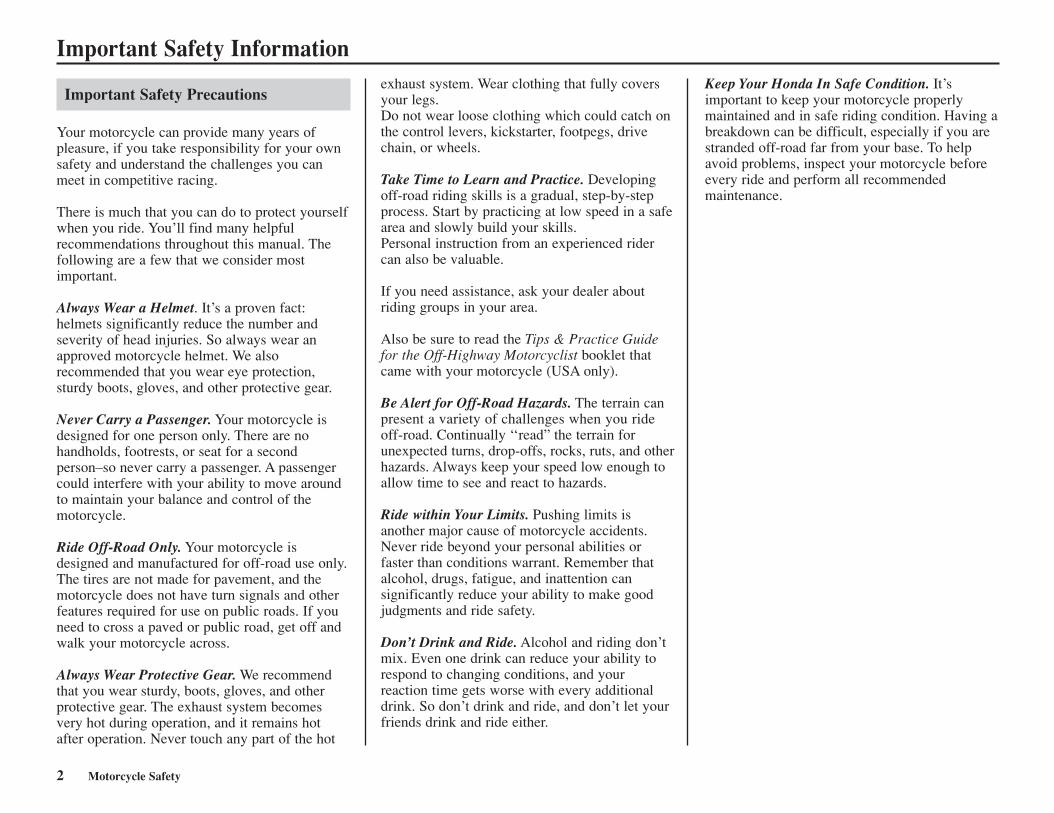
Your motorcycle can provide many years ofpleasure, if you take responsibility for your ownsafety and understand the challenges you canmeet in competitive racing.
There is much that you can do to protect yourselfwhen you ride. You’ll find many helpfulrecommendations throughout this manual. Thefollowing are a few that we consider mostimportant.
Always Wear a Helmet. It’s a proven fact:helmets significantly reduce the number andseverity of head injuries. So always wear anapproved motorcycle helmet. We alsorecommended that you wear eye protection,sturdy boots, gloves, and other protective gear.
Never Carry a Passenger. Your motorcycle isdesigned for one person only. There are nohandholds, footrests, or seat for a secondperson–so never carry a passenger. A passengercould interfere with your ability to move aroundto maintain your balance and control of themotorcycle.
Ride Off-Road Only. Your motorcycle isdesigned and manufactured for off-road use only.The tires are not made for pavement, and themotorcycle does not have turn signals and otherfeatures required for use on public roads. If youneed to cross a paved or public road, get off andwalk your motorcycle across.
Always Wear Protective Gear. We recommendthat you wear sturdy, boots, gloves, and otherprotective gear. The exhaust system becomesvery hot during operation, and it remains hotafter operation. Never touch any part of the hot
Keep Your Honda In Safe Condition. It’simportant to keep your motorcycle properlymaintained and in safe riding condition. Having abreakdown can be difficult, especially if you arestranded off-road far from your base. To helpavoid problems, inspect your motorcycle beforeevery ride and perform all recommendedmaintenance.
2 Motorcycle Safety
exhaust system. Wear clothing that fully coversyour legs.Do not wear loose clothing which could catch onthe control levers, kickstarter, footpegs, drivechain, or wheels.
Take Time to Learn and Practice. Developingoff-road riding skills is a gradual, step-by-stepprocess. Start by practicing at low speed in a safearea and slowly build your skills.Personal instruction from an experienced ridercan also be valuable.
If you need assistance, ask your dealer aboutriding groups in your area.
Also be sure to read the Tips & Practice Guidefor the Off-Highway Motorcyclist booklet thatcame with your motorcycle (USA only).
Be Alert for Off-Road Hazards. The terrain canpresent a variety of challenges when you rideoff-road. Continually ‘‘read” the terrain forunexpected turns, drop-offs, rocks, ruts, and otherhazards. Always keep your speed low enough toallow time to see and react to hazards.
Ride within Your Limits. Pushing limits isanother major cause of motorcycle accidents.Never ride beyond your personal abilities orfaster than conditions warrant. Remember thatalcohol, drugs, fatigue, and inattention cansignificantly reduce your ability to make goodjudgments and ride safety.
Don’t Drink and Ride. Alcohol and riding don’tmix. Even one drink can reduce your ability torespond to changing conditions, and yourreaction time gets worse with every additionaldrink. So don’t drink and ride, and don’t let yourfriends drink and ride either.
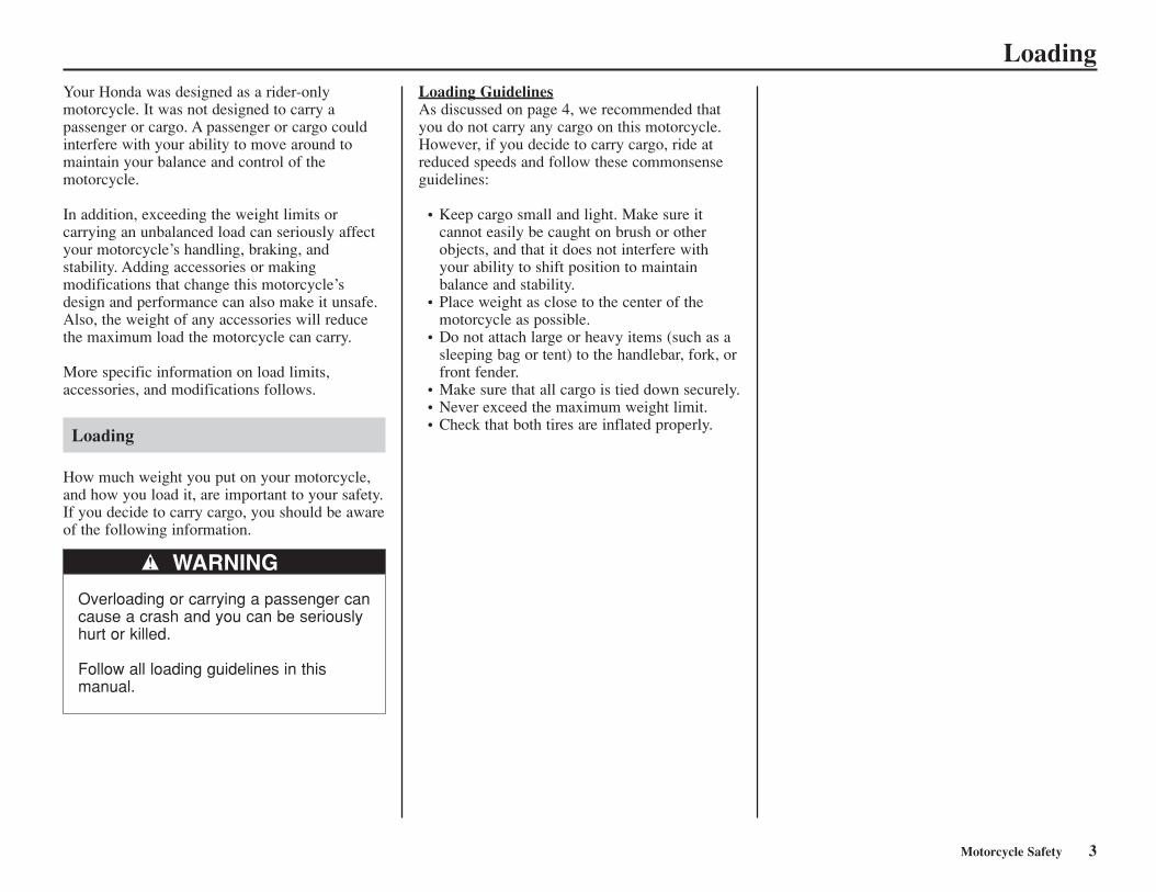
LoadingYour Honda was designed as a rider-onlymotorcycle. It was not designed to carry apassenger or cargo. A passenger or cargo couldinterfere with your ability to move around tomaintain your balance and control of themotorcycle.
In addition, exceeding the weight limits orcarrying an unbalanced load can seriously affectyour motorcycle’s handling, braking, andstability. Adding accessories or makingmodifications that change this motorcycle’sdesign and performance can also make it unsafe.Also, the weight of any accessories will reducethe maximum load the motorcycle can carry.
More specific information on load limits,accessories, and modifications follows.
Loading
How much weight you put on your motorcycle,and how you load it, are important to your safety.If you decide to carry cargo, you should be awareof the following information.
Loading GuidelinesAs discussed on page 4, we recommended thatyou do not carry any cargo on this motorcycle.However, if you decide to carry cargo, ride atreduced speeds and follow these commonsenseguidelines:
• Keep cargo small and light. Make sure itcannot easily be caught on brush or otherobjects, and that it does not interfere withyour ability to shift position to maintainbalance and stability.
• Place weight as close to the center of themotorcycle as possible.
• Do not attach large or heavy items (such as asleeping bag or tent) to the handlebar, fork, orfront fender.
• Make sure that all cargo is tied down securely.• Never exceed the maximum weight limit.• Check that both tires are inflated properly.
Motorcycle Safety 3
WARNING
Overloading or carrying a passenger cancause a crash and you can be seriouslyhurt or killed.
Follow all loading guidelines in thismanual.
Accessories & ModificationsAccessoriesWe strongly recommend that you use onlygenuine Honda accessories that have beenspecifically designed and tested for yourmotorcycle. Because Honda cannot test all otheraccessories, you must be personally responsiblefor proper selection, installation, and use of non-Honda accessories. Check with your dealer forassistance and always follow this guideline:
• Make sure the accessory does not reduceground clearance and lean angle, limitsuspension travel or steering travel, alter yourriding position, or interfere with operating anycontrols.
ModificationsWe strongly advise you not to remove anyoriginal equipment or modify your motorcycle inany way that would change its design oroperation. Such changes could seriously impairyour motorcycle’s handling, stability, andbraking, making it unsafe to ride.
We also advice you not to make anymodifications or remove any equipment (such asthe USDA qualified spark arrester or emissioncontrol system components) that would make themotorcycle illegal in your area.
4 Motorcycle Safety
Accessories & Modifications
Modifying your motorcycle or using non-Hondaaccessories can make your motorcycle unsafe.
Before you consider making any modifications oradding an accessory, be sure to read thefollowing information.
WARNINGImproper accessories or modificationscan cause a crash in which you can beseriously hurt or killed.
Follow all instructions in this owner’smanual regarding modifications andaccessories.
Motorcycle Safety 5
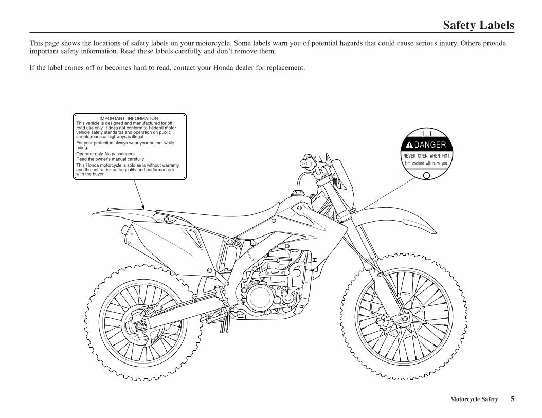
Safety LabelsThis page shows the locations of safety labels on your motorcycle. Some labels warn you of potential hazards that could cause serious injury. Othere provideimportant safety information. Read these labels carefully and don’t remove them.
If the label comes off or becomes hard to read, contact your Honda dealer for replacement.

6 Motorcycle Safety

Operating Controls 7
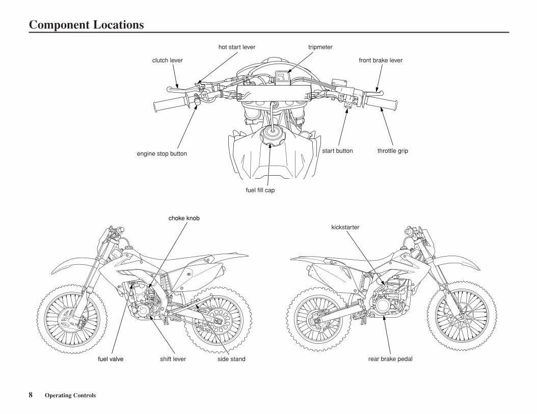
Operating ControlsRead this section carefully before you ride. Itpresents the location of the basic controls on yourmotorcycle.
Component Locations ..........................................8
8 Operating Controls
Component Locations
clutch lever
hot start lever
front brake lever
engine stop button
fuel fill cap
throttle grip
tripmeter
start button
choke knob
fuel valve shift lever side stand
kickstarter
rear brake pedal
Before Riding 9
Before each ride, you need to make sure you andyour Honda are both ready to ride. To help getyou prepared, this section discusses how to evaluate your riding readiness, and what itemsyou should check on your motorcycle.
For information about suspension, carburetionand other adjustment see page 103.
Before RidingAre You Ready to Ride?.....................................10Is Your Motorcycle Ready to Ride?...................11
Pre-ride Inspection ...........................................11
10 Before Riding
Are You Ready to Ride?Before riding your CRF for the first time, werecommend that you read this owner’s manual,make sure you understand the safety messages,and know how to operate the controls.
Before each ride, it’s also important to make sureyou and your motorcycle are both ready to ride.
For information about suspension, carburetor,and other adjustments, see page 103.
Whether you’re preparing for competition or forpractice, always make sure you are.
• In good physical and mental condition
• Free of alcohol and drugs
• Wearing an approved helmet, eye protection,and other appropriate riding gear
Although complete protection is not possible,wearing the proper gear can reduce the chance orseverity of injury when you ride.
WARNINGNot wearing a helmet increases thechance of serious injury or death in acrash.
Be sure you always wear a helmet, eyeprotection and other protective apparelwhen you ride.
Before Riding 11
Is Your Motorcycle Ready to Ride?Competitive riding can be tough on a motorcycle,so it’s important to inspect your CRF and correctany problems you find before each ride. Checkthe following items (page numbers are at theright):
Pre-ride Inspection
Check the following before each ride: • Engine oil level .............................................44• Transmission oil level...................................47• Coolant for proper level................................48• Cooling system and hoses for condition.......49• Spark plug for proper heat range, carbon
fouling and high tension cord terminal forlooseness .......................................................61
• Air cleaner for condition and contamination................................................51
• Clutch operation and free play .....................56• Steering head bearings and related parts
for condition..................................................97• Carburetor throttle operation ........................55• Engine idle speed for stable and proper
RPM............................................................132• Tires for damage or improper inflation
pressure ........................................................91• Spokes for looseness.....................................90• Rim locks for looseness................................90• Front and rear suspension for proper
operation ..................................................82,83• Front and rear brakes, check operation ........87• Drive chain for wear or damage and
adequate lubrication......................................94• Drive chain guide, sliders and guide rollers
for damage or wear .......................................96• Exhaust pipe/Muffler inspection,
removal and installation................................64• Every possible part for looseness (such as
cylinder head nuts, engine mounting bolts,axle nuts, handlebar holder bolts, fork tripleclamp bolts, drive chain adjuster, drive chainguide, wire harness connectors, kickstartermounting bolt, etc.) .............................151-153
WARNINGImproperly maintaining this motorcycle orfailing to correct a problem before ridingcan cause a crash in which you can beseriously hurt or killed.
Always perform a pre-ride inspectionbefore every ride and correct any problems.

12 Before Riding
Basic Operating Instructions 13Basic Operating Instructions 13
Basic Operating InstructionsThis section gives basic information on how tostart and stop your engine as well as break-inguidelines.
Safe Riding Precautions .....................................14Starting & Stopping the Engine .........................15
Preparation ....................................................15Fuel Valve .....................................................15Starting Procedure ........................................15Flooded Engine.............................................16How to Stop the Engine................................16
Shifting Gears.....................................................17Braking ...............................................................18Parking ...............................................................19Post-ride Inspection............................................20Break-in Guidelines ...........................................21
Tripmeter
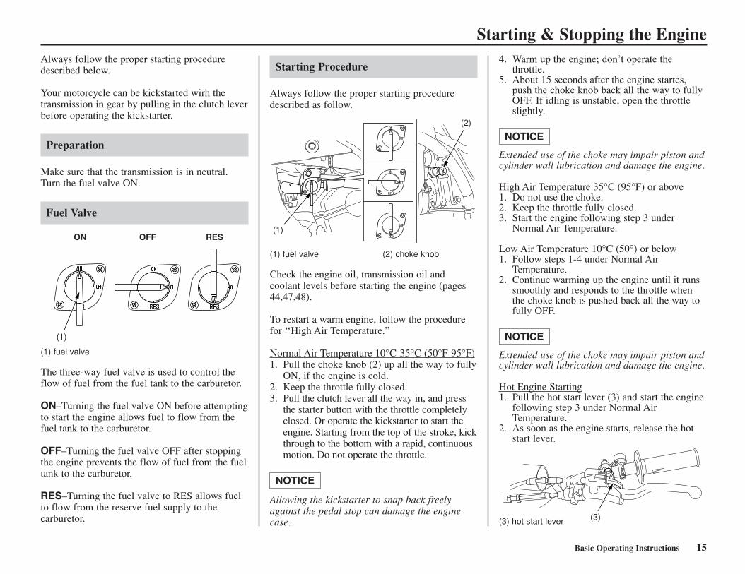
The tripmeter (1) is used to record the distancetraveled (USA: miles, Canada: kilometers) pertrip or section of route.To operate, pull the tripmeter reset knob (2) out(OFF) and turn it until the meter shows all zeros(0), then push the knob in (ON).
14 Basic Operating Instructions14 Basic Operating Instructions
Basic Operating Instructions
Safe Riding Precautions
Before riding your motorcycle for the first time,please review the Important Safety Precautionbeginning on page 2 and the previous section,titled Before Riding.
For your safety, avoid starting or operating theengine in an enclosed area such as a garage.Your motorcycle’s exhaust contains poisonouscarbon monoxide gas which can collect rapidly inan enclosed area and cause illness or death.
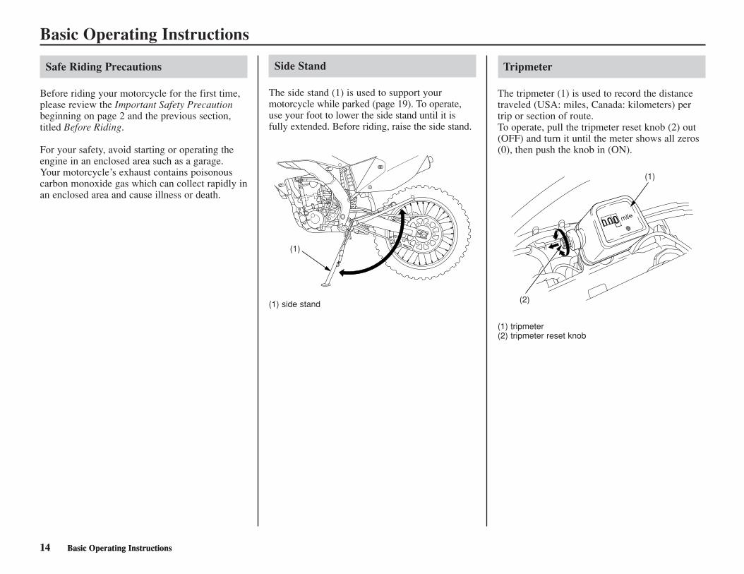
(1) side stand
(1) tripmeter(2) tripmeter reset knob
(1)
(2)
(1)
Side Stand
The side stand (1) is used to support yourmotorcycle while parked (page 19). To operate,use your foot to lower the side stand until it isfully extended. Before riding, raise the side stand.
Starting & Stopping the EngineAlways follow the proper starting proceduredescribed below.
Your motorcycle can be kickstarted wirh thetransmission in gear by pulling in the clutch leverbefore operating the kickstarter.
Preparation
Make sure that the transmission is in neutral.Turn the fuel valve ON.
Fuel Valve
Starting Procedure
Always follow the proper starting proceduredescribed as follow.
4. Warm up the engine; don’t operate thethrottle.
5. About 15 seconds after the engine startes,push the choke knob back all the way to fullyOFF. If idling is unstable, open the throttleslightly.
Extended use of the choke may impair piston andcylinder wall lubrication and damage the engine.
High Air Temperature 35°C (95°F) or above1. Do not use the choke.2. Keep the throttle fully closed.3. Start the engine following step 3 under
Normal Air Temperature.
Low Air Temperature 10°C (50°) or below1. Follow steps 1-4 under Normal Air
Temperature.2. Continue warming up the engine until it runs
smoothly and responds to the throttle whenthe choke knob is pushed back all the way tofully OFF.
Extended use of the choke may impair piston andcylinder wall lubrication and damage the engine.
Hot Engine Starting1. Pull the hot start lever (3) and start the engine
following step 3 under Normal AirTemperature.
2. As soon as the engine starts, release the hotstart lever.
NOTICE
NOTICE
Basic Operating Instructions 15
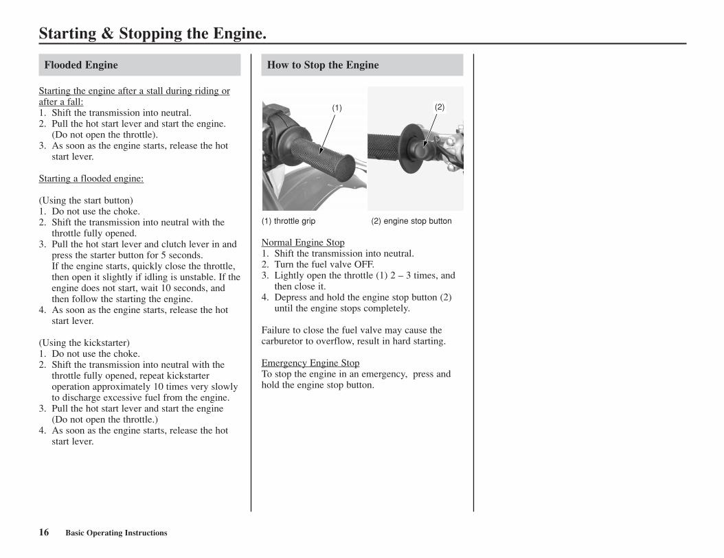
(1) fuel valve
The three-way fuel valve is used to control theflow of fuel from the fuel tank to the carburetor.
ON–Turning the fuel valve ON before attemptingto start the engine allows fuel to flow from thefuel tank to the carburetor.
OFF–Turning the fuel valve OFF after stoppingthe engine prevents the flow of fuel from the fueltank to the carburetor.
RES–Turning the fuel valve to RES allows fuelto flow from the reserve fuel supply to thecarburetor.
(1) fuel valve (2) choke knob
Check the engine oil, transmission oil andcoolant levels before starting the engine (pages44,47,48).
To restart a warm engine, follow the procedurefor ‘‘High Air Temperature.”
Normal Air Temperature 10°C-35°C (50°F-95°F)1. Pull the choke knob (2) up all the way to fully
ON, if the engine is cold.2. Keep the throttle fully closed.3. Pull the clutch lever all the way in, and press
the starter button with the throttle completelyclosed. Or operate the kickstarter to start theengine. Starting from the top of the stroke, kickthrough to the bottom with a rapid, continuousmotion. Do not operate the throttle.
Allowing the kickstarter to snap back freelyagainst the pedal stop can damage the enginecase.
NOTICE
ON OFF RES
(1)
(1)
(2)
(3)(3) hot start lever
Starting & Stopping the Engine.
Flooded Engine
Starting the engine after a stall during riding orafter a fall:1. Shift the transmission into neutral.2. Pull the hot start lever and start the engine.
(Do not open the throttle).3. As soon as the engine starts, release the hot
start lever.
Starting a flooded engine:
(Using the start button)1. Do not use the choke.2. Shift the transmission into neutral with the
throttle fully opened.3. Pull the hot start lever and clutch lever in and
press the starter button for 5 seconds.If the engine starts, quickly close the throttle,then open it slightly if idling is unstable. If theengine does not start, wait 10 seconds, andthen follow the starting the engine.
4. As soon as the engine starts, release the hotstart lever.
(Using the kickstarter)1. Do not use the choke.2. Shift the transmission into neutral with the
throttle fully opened, repeat kickstarteroperation approximately 10 times very slowlyto discharge excessive fuel from the engine.
3. Pull the hot start lever and start the engine(Do not open the throttle.)
4. As soon as the engine starts, release the hotstart lever.
16 Basic Operating Instructions
How to Stop the Engine
(1) (2)
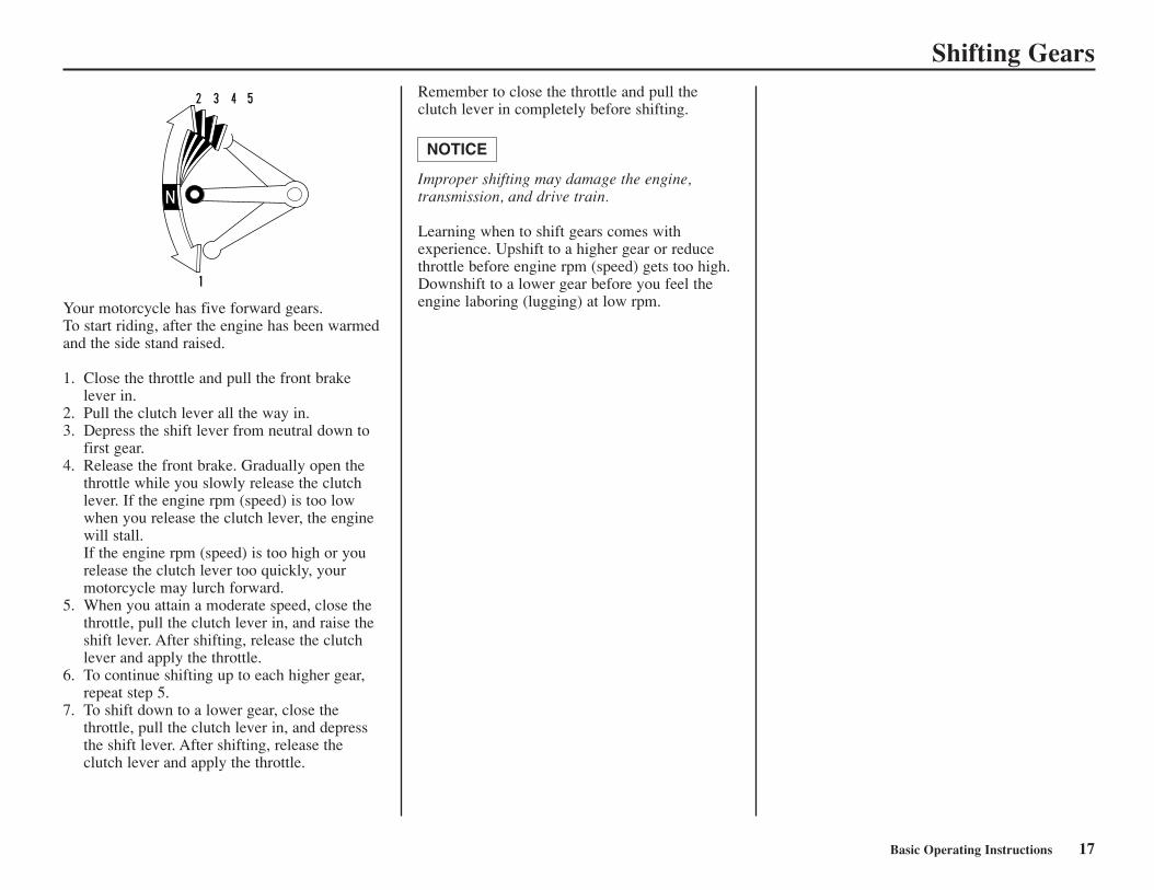
(1) throttle grip (2) engine stop button
Normal Engine Stop1. Shift the transmission into neutral. 2. Turn the fuel valve OFF. 3. Lightly open the throttle (1) 2 – 3 times, and
then close it. 4. Depress and hold the engine stop button (2)
until the engine stops completely.
Failure to close the fuel valve may cause the carburetor to overflow, result in hard starting.
Emergency Engine StopTo stop the engine in an emergency, press andhold the engine stop button.
Shifting GearsRemember to close the throttle and pull theclutch lever in completely before shifting.
Improper shifting may damage the engine,transmission, and drive train.
Learning when to shift gears comes withexperience. Upshift to a higher gear or reducethrottle before engine rpm (speed) gets too high.Downshift to a lower gear before you feel theengine laboring (lugging) at low rpm.
NOTICE
Basic Operating Instructions 17
Your motorcycle has five forward gears.To start riding, after the engine has been warmedand the side stand raised.
1. Close the throttle and pull the front brakelever in.
2. Pull the clutch lever all the way in.3. Depress the shift lever from neutral down to
first gear.4. Release the front brake. Gradually open the
throttle while you slowly release the clutchlever. If the engine rpm (speed) is too lowwhen you release the clutch lever, the enginewill stall.If the engine rpm (speed) is too high or yourelease the clutch lever too quickly, yourmotorcycle may lurch forward.
5. When you attain a moderate speed, close thethrottle, pull the clutch lever in, and raise theshift lever. After shifting, release the clutchlever and apply the throttle.
6. To continue shifting up to each higher gear,repeat step 5.
7. To shift down to a lower gear, close thethrottle, pull the clutch lever in, and depressthe shift lever. After shifting, release theclutch lever and apply the throttle.
BrakingTo slow or stop, apply the front brake and rearbrake smoothly, while down shifting to matchyour speed. Gradually increase braking as youfeel the brakes slowing your speed. To preventstalling the engine, pull the clutch lever in beforecoming to a complete stop. For support, put yourleft foot down first, then your right foot whenyou are through using the rear brake.
For maximum braking, close the throttle andfirmly apply the brake lever and pedal controls.
Applying the brakes too hard may cause thewheels to lock and slide, reducing control of yourmotorcycle. If this happens, release the brakecontrols, steer straight ahead until you regaincontrol, then reapply the brakes more gently.
Generally, reduce your speed or complatebraking before beginning a turn. Avoid braking orclosing the throttle quickly while turning. Eitheraction may cause one or both wheels to slip. Anywheel slip will reduce your control of yourmotorcycle.
When riding in wet or raining conditions, or onloose surfaces, the ability to maneuver and stopwill be reduced. All of your actions should besmooth under these conditions. Rapidacceleration, braking, or turning may cause lossof control. For your safety, exercise extremecaution when braking, accelerating, or turning.
When descending a long, steep grade, use enginecompression braking by downshifting, withintermittent use of both brakes.
When you brake to a stop, pull the clutch lever inbefore stopping completely to prevent stalling theengine. For support, put your left foot on theground first, then your right foot when you’rethrough braking.
18 Basic Operating Instructions
ParkingLower the side stand to support your motorcycle.If you’re through riding for the day, also turn thefuel valve OFF. Always choose a level place topark.
Basic Operating Instructions 19
Post-ride InspectionWhen you return home after riding thoroughlyclean your motorcycle and remove any dirt, mud,brush, rocks or other objects you may havepicked up along the way.
After cleaning, carefully inspect your motorcyclefor leaks or damage.
Be sure to lubricate the drive chain (page 96) toprevent rusting.
20 Basic Operating Instructions
Basic Operating Instructions 21
Break-in GuidelinesHelp assure your CRF’s future reliability andperformance by paying extra attention to howyou ride during the first operating day or 15miles (25 km).During this period, avoid full-throttle starts andrapid acceleration.
This same procedure should be followed eachtime when:
• piston is replaced• piston rings are replaced• cylinder is replaced• crankshaft or crank bearings are replaced

22 Basic Operating Instructions
Servicing Your Honda 23
Servicing Your HondaKeeping your motorcycle well maintained isabsolutely essential to your safety. It’s also agood way to protect your investment, get maximum performance, avoid breakdowns, andhave more fun.
To help keep your motorcycle in good shape, thissection includes a Maintenance Schedule forrequired servicing and step-by-step instructionsfor specific maintenance tasks. You’ll also findimportant safety precautions, information on oils,and tips for keeping your Honda looking good.
A CDI (Capacitive Discharge Ignition) system isused on this motorcycle; consequently, routineignition timing adjustment is unnecessary. If youwant to check the ignition timing, refer to theHonda Service Manual (page 164).
Before You Service Your HondaThe Importance of Maintenance ........................24Maintenance Safety ............................................25
Important Safety Precautions........................25Maintenance Schedule .......................................26General Competition Maintenance ....................29Before & After Competition Maintenance.........33
Between Motos & Practice Maintenance .....33After Competition Maintenance ...................33
Service PreparationsComponent Locations ........................................35Seat Removal .....................................................36Fuel Tank Removal ............................................37Subframe Upright Position.................................39
Service Procedures
Fluids & FiltersFuel System........................................................41Engine Oil ..........................................................43Transmission Oil ................................................46Coolant ...............................................................48Air Cleaner .........................................................51Crankcase Breather ............................................53
EngineThrottle ...............................................................54Clutch System ....................................................56Hot Start Lever...................................................60Spark Plug ..........................................................61Exhaust Pipe/Muffler .........................................62Spark Arrester.....................................................65Valve Clearance..................................................66Piston/Piston Rings/Piston Pin...........................74
ChassisSuspension..........................................................82
Front Suspension Inspection........................82Rear Suspension Inspection.........................83Recommended Fork Oil ..............................84Fork Oil Change ..........................................84
Brakes.................................................................86Wheels ................................................................90Tires & Tubes .....................................................91Side Stand...........................................................93Drive Chain ........................................................94Additional Maintenance Procedures ..................97
ElectricalBattery ................................................................99Headlight & Taillight .......................................100
Appearance Care ..............................................101
24 Servicing Your Honda
WARNINGImproperly maintaining this motorcycle orfailing to correct a problem before youride can cause a crash in which you canbe seriously hurt or killed.
Always follow the inspection and maintenance recommendations andschedules in this owner’s manual.
The Importance of MaintenanceA well-maintained motorcycle is essential forsafe, economical, and trouble-free riding. It willalso help reduce air pollution. Careful pre-rideinspections and good maintenance are especiallyimportant because your motorcycle is designed tobe ridden over rough off-road terrain.
To help you properly care for your motorcycle,this section of the manual provides aMaintenance Schedule. The service intervals inthis schedule are based on average ridingconditions.
More frequent service is needed if you subjectyour motorcycle to severe use or ride inunusually wet or dusty areas.
Frequent servicing of the air cleaner is especiallyimportant to help you avoid a possible costlyengine repair.
If your motorcycle overturns or is involved in acrash, be sure your Honda dealer inspects allmajor parts, even if you are able to make somerepairs.
Remember, proper maintenance is your responsibility. Be sure to inspect your motorcycle before each ride and follow theMaintenance Schedule in this section.
Servicing Your Honda 25
Maintenance SafetyThis section includes instructions on how to perform some important maintenance tasks.Some of the most important safety precautionsfollow. However, we cannot warn you of everyconceivable hazard that can arise in performingmaintenance. Only you can decide whether ornot you should perform a given task.
Important Safety Precautions
• Make sure the engine is off before you beginany maintenance or repairs.This will help eliminate several potential hazards:
Carbon monoxide poisoning from engineexhaust. Be sure there is adequate ventilationwhenever you operate the engine.
Burns from hot motorcycle parts. Let theengine and exhaust system cool before touching.
Injury from moving parts. Do not run theengine unless instructed to do so.
• Read the instructions before you begin, andmake sure you have the tools and skillsrequired.
• To help prevent the motorcycle from fallingover, park it on a firm, level surface, using theside stand or a maintenance stand to providesupport.
• To reduce the possibility of a fire or explosion, be careful when working aroundgasoline. Use only a non-flammable (highflash point) solvent such as kerosene —notgasoline— to clean parts. Keep cigarettes,sparks, and flames away from all fuel-relatedparts.
WARNINGFailure to properly follow maintenanceinstructions and precautions can causeyou to be seriously hurt or killed.
Always follow the procedures and precautions in this owner’s manual.
26 Servicing Your Honda
Maintenance ScheduleTo maintain the safety and reliability of yourmotorcycle, regular inspection and service isrequired as shown in the MaintenanceSchedules – Regular OFF ROAD (non-competition) Use and Competition Use-thatfollow.
The Maintenance Schedule lists items that can beperformed with basic mechanical skills and handtools. Procedures for these items are provided inthis manual.
The Maintenance Schedule also includes itemsthat involve more extensive procedures and mayrequire special training, tools, and equipment.Therefore, we recommend that you have yourHonda dealer perform these tasks unless youhave advanced mechanical skills and the requiredtools. Procedures for items in this schedule areprovided in a service manual available for purchase from your dealer (page 166).
Because your motorcycle does not have anodometer, service intervals in the maintenanceschedules are expressed in terms of riding daysas well as miles. To avoid overlooking requiredservice, we urge you to develop a convenientway to record the number of days and/or milesyou ride.
If you do not feel capable of performing a giventask or need assistance, remember that yourHonda dealer knows your motorcycle best and isfully equipped to maintain and repair it. If youdecide to do your own maintenance, use onlygenuine Honda parts or their equivalents forrepair or replacement to ensure the best qualityand reliability.
Perform the pre-ride inspection (page 11) at eachscheduled maintenance period.
Each item on the maintenance schedule requiressome mechanical knowledge. Certain items(particularly those marked *and**) may requiremore technical information and tools. Consultyour Honda dealer.
* Should be serviced by your Honda dealer,unless the ower has the proper tools andservice date and is mechanically qualified.Refer to the official Honda Service Manual(page 164).
** In the interest of safety, we recommend theseitems be serviced only by your Honda dealer.
Maintenance Procedures:I: inspect and clean, adjust, lubricate, or replace,
if necessaryC: cleanL: lubricateR: replace
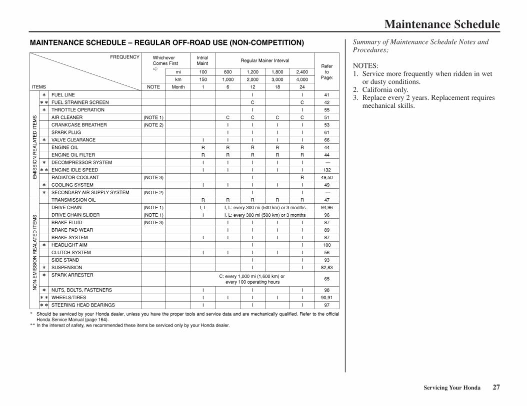
Maintenance ScheduleSummary of Maintenance Schedule Notes andProcedures;
NOTES:1. Service more frequently when ridden in wet
or dusty conditions.2. California only.3. Replace every 2 years. Replacement requires
mechanical skills.
Servicing Your Honda 27
FUEL LINE
FUEL STRAINER SCREEN
THROTTLE OPERATION
AIR CLEANER
CRANKCASE BREATHER
SPARK PLUG
VALVE CLEARANCE
ENGINE OIL
ENGINE OIL FILTER
DECOMPRESSOR SYSTEM
ENGINE IDLE SPEED
RADIATOR COOLANT
COOLING SYSTEM
SECONDARY AIR SUPPLY SYSTEM
TRANSMISSION OIL
DRIVE CHAIN
DRIVE CHAIN SLIDER
BRAKE FLUID
BRAKE PAD WEAR
BRAKE SYSTEM
HEADLIGHT AIM
CLUTCH SYSTEM
SIDE STAND
SUSPENSION
SPARK ARRESTER
NUTS, BOLTS, FASTENERS
WHEELS/TIRES
STEERING HEAD BEARINGS
(NOTE 1)
(NOTE 2)
(NOTE 3)
(NOTE 2)
(NOTE 1)
(NOTE 1)
(NOTE 3)
I
R
R
I
I
I
R
I, L
I
I
I
I
I
I
C
I
I
I
R
R
I
I
I
R
I
I
I
I
I
I
C
I
C
I
I
I
R
R
I
I
I
I
I
R
I
I
I
I
I
I
I
I
I
I
C
I
I
I
R
R
I
I
I
R
I
I
I
I
I
I
C
I
C
I
I
I
R
R
I
I
R
I
I
R
I
I
I
I
I
I
I
I
I
I
41
42
55
51
53
61
66
44
44
—
132
49,50
49
—
47
94,96
96
87
89
87
100
56
93
82,83
65
98
90,91
97
FREQUENCY
ITEMS
EM
ISS
ION
RE
ALA
TE
D IT
EM
SN
ON
-EM
ISS
ION
RE
ALA
TE
D IT
EM
S
NOTE
mi
km
Month
100
150
1
600
1,000
6
1,200
2,000
12
I, L: every 300 mi (500 km) or 3 months
I, L: every 300 mi (500 km) or 3 months
C: every 1,000 mi (1,600 km) or every 100 operating hours
1,800
3,000
18
2,400
4,000
24
Referto
Page:
WhicheverComes First
IntrialMaint
Regular Mainer Interval
Should be serviced by your Honda dealer, unless you have the proper tools and service data and are mechanically qualified. Refer to the official Honda Service Manual (page 164).In the interest of safety, we recommended these items be serviced only by your Honda dealer.
*
**
MAINTENANCE SCHEDULE – REGULAR OFF-ROAD USE (NON-COMPETITION)
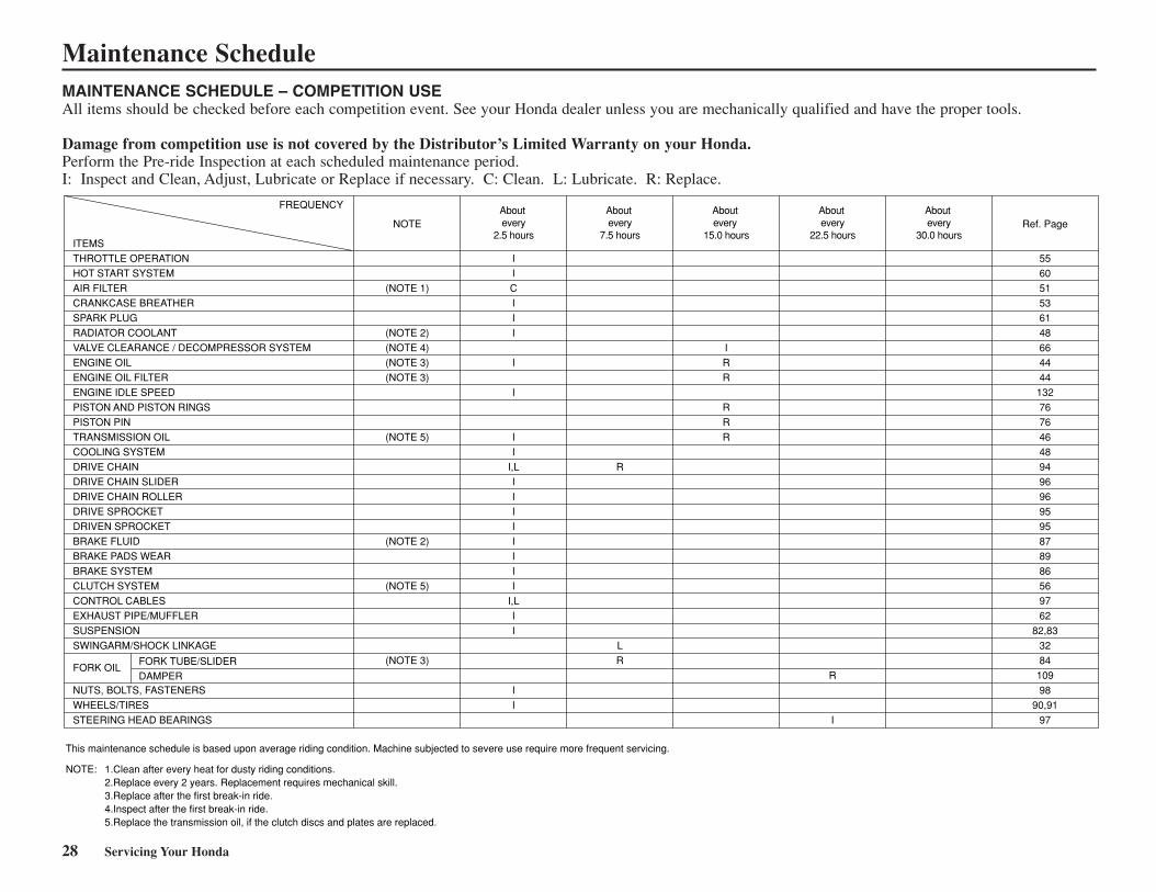
MAINTENANCE SCHEDULE – COMPETITION USEAll items should be checked before each competition event. See your Honda dealer unless you are mechanically qualified and have the proper tools.
Damage from competition use is not covered by the Distributor’s Limited Warranty on your Honda.Perform the Pre-ride Inspection at each scheduled maintenance period. I: Inspect and Clean, Adjust, Lubricate or Replace if necessary. C: Clean. L: Lubricate. R: Replace.
28 Servicing Your Honda
Maintenance Schedule
ITEMS
THROTTLE OPERATION
HOT START SYSTEM
AIR FILTER
CRANKCASE BREATHER
SPARK PLUG
RADIATOR COOLANT
VALVE CLEARANCE / DECOMPRESSOR SYSTEM
ENGINE OIL
ENGINE OIL FILTER
ENGINE IDLE SPEED
PISTON AND PISTON RINGS
PISTON PIN
TRANSMISSION OIL
COOLING SYSTEM
DRIVE CHAIN
DRIVE CHAIN SLIDER
DRIVE CHAIN ROLLER
DRIVE SPROCKET
DRIVEN SPROCKET
BRAKE FLUID
BRAKE PADS WEAR
BRAKE SYSTEM
CLUTCH SYSTEM
CONTROL CABLES
EXHAUST PIPE/MUFFLER
SUSPENSION
SWINGARM/SHOCK LINKAGE
FORK OIL
NUTS, BOLTS, FASTENERS
WHEELS/TIRES
STEERING HEAD BEARINGS
(NOTE 1)
(NOTE 2)
(NOTE 4)
(NOTE 3)
(NOTE 3)
(NOTE 5)
(NOTE 2)
(NOTE 5)
(NOTE 3)
55
60
51
53
61
48
66
44
44
132
76
76
46
48
94
96
96
95
95
87
89
86
56
97
62
82,83
32
84
109
98
90,91
97
I
I
C
I
I
I
I
I
I
I
I,L
I
I
I
I
I
I
I
I
I,L
I
I
I
I
R
L
R
I
R
R
R
R
R
R
I
FORK TUBE/SLIDER
DAMPER
FREQUENCY
NOTE Ref. PageAbout every
2.5 hours
About every
7.5 hours
About every
15.0 hours
About every
22.5 hours
About every
30.0 hours
This maintenance schedule is based upon average riding condition. Machine subjected to severe use require more frequent servicing.
NOTE: 1.Clean after every heat for dusty riding conditions. 2.Replace every 2 years. Replacement requires mechanical skill. 3.Replace after the first break-in ride. 4.Inspect after the first break-in ride.5.Replace the transmission oil, if the clutch discs and plates are replaced.
Servicing Your Honda 29
General Competition MaintenancePerform maintenance on firm, level ground usingthe side stand, a workstand, or equivalent support.
Use genuine Honda parts or their equivalentwhen servicing your motorcycle.
Clean parts in non-flammable (high flash point)cleaning solvent (such as kerosene) when disassembling. Lubricate any sliding surface, O-rings, and seals before reassembling. Greaseparts by coating or filling where specified.
After any engine disassembly, always install newgaskets, O-rings, cotter pins, piston pin clips,snap rings, etc. when reassembling. Afterreassembly, check all parts for proper installationand operation.
All Pre-ride Inspection ItemsRefer to Pre-ride Inspection page 11.
30 Servicing Your Honda
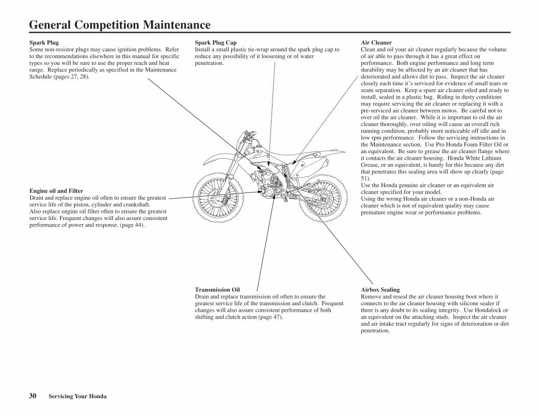
Spark Plug Some non-resistor plugs may cause ignition problems. Refer to the recommendations elsewhere in this manual for specific types so you will be sure to use the proper reach and heat range. Replace periodically as specified in the Maintenance Schedule (pages 27, 28).
Engine oil and Filter Drain and replace engine oil often to ensure the greatest service life of the piston, cylinder and crankshaft.Also replace engine oil filter often to ensure the greatest service life. Frequent changes will also assure consistent performance of power and response. (page 44).
Spark Plug Cap Install a small plastic tie-wrap around the spark plug cap to reduce any possibility of it loosening or of water penetration.
Air Cleaner Clean and oil your air cleaner regularly because the volume of air able to pass through it has a great effect on performance. Both engine performance and long term durability may be affected by an air cleaner that has deteriorated and allows dirt to pass. Inspect the air cleaner closely each time it’s serviced for evidence of small tears or seam separation. Keep a spare air cleaner oiled and ready to install, sealed in a plastic bag. Riding in dusty conditions may require servicing the air cleaner or replacing it with a pre-serviced air cleaner between motos. Be careful not to over oil the air cleaner. While it is important to oil the air cleaner thoroughly, over oiling will cause an overall rich running condition, probably more noticeable off idle and in low rpm performance. Follow the servicing instructions in the Maintenance section. Use Pro Honda Foam Filter Oil or an equivalent. Be sure to grease the air cleaner flange where it contacts the air cleaner housing. Honda White Lithium Grease, or an equivalent, is handy for this because any dirt that penetrates this sealing area will show up clearly (page 51). Use the Honda genuine air cleaner or an equivalent air cleaner specified for your model. Using the wrong Honda air cleaner or a non-Honda air cleaner which is not of equivalent quality may cause premature engine wear or performance problems.
Transmission Oil Drain and replace transmission oil often to ensure the greatest service life of the transmission and clutch. Frequent changes will also assure consistent performance of both shifting and clutch action (page 47).
Airbox Sealing Remove and reseal the air cleaner housing boot where it connects to the air cleaner housing with silicone sealer if there is any doubt to its sealing integrity. Use Hondalock or an equivalent on the attaching studs. Inspect the air cleaner and air intake tract regularly for signs of deterioration or dirt penetration.
General Competition Maintenance
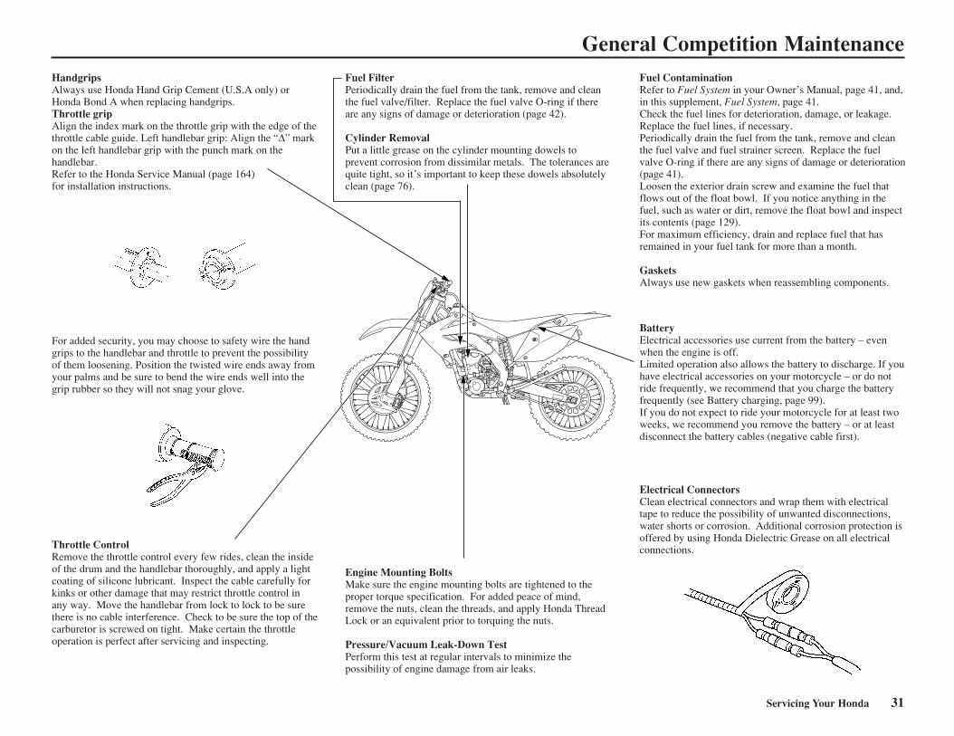
General Competition MaintenanceHandgripsAlways use Honda Hand Grip Cement (U.S.A only) or Honda Bond A when replacing handgrips.Throttle gripAlign the index mark on the throttle grip with the edge of the throttle cable guide. Left handlebar grip: Align the “∆” mark on the left handlebar grip with the punch mark on the handlebar. Refer to the Honda Service Manual (page 164) for installation instructions.
For added security, you may choose to safety wire the hand grips to the handlebar and throttle to prevent the possibility of them loosening. Position the twisted wire ends away from your palms and be sure to bend the wire ends well into the grip rubber so they will not snag your glove.
Throttle ControlRemove the throttle control every few rides, clean the inside of the drum and the handlebar thoroughly, and apply a light coating of silicone lubricant. Inspect the cable carefully for kinks or other damage that may restrict throttle control in any way. Move the handlebar from lock to lock to be sure there is no cable interference. Check to be sure the top of the carburetor is screwed on tight. Make certain the throttle operation is perfect after servicing and inspecting.
Fuel FilterPeriodically drain the fuel from the tank, remove and clean the fuel valve/filter. Replace the fuel valve O-ring if there are any signs of damage or deterioration (page 42).
Cylinder RemovalPut a little grease on the cylinder mounting dowels to prevent corrosion from dissimilar metals. The tolerances are quite tight, so it’s important to keep these dowels absolutely clean (page 76).
Fuel ContaminationRefer to Fuel System in your Owner’s Manual, page 41, and, in this supplement, Fuel System, page 41. Check the fuel lines for deterioration, damage, or leakage. Replace the fuel lines, if necessary. Periodically drain the fuel from the tank, remove and clean the fuel valve and fuel strainer screen. Replace the fuel valve O-ring if there are any signs of damage or deterioration (page 41). Loosen the exterior drain screw and examine the fuel that flows out of the float bowl. If you notice anything in the fuel, such as water or dirt, remove the float bowl and inspect its contents (page 129). For maximum efficiency, drain and replace fuel that has remained in your fuel tank for more than a month.
GasketsAlways use new gaskets when reassembling components.
Engine Mounting BoltsMake sure the engine mounting bolts are tightened to the proper torque specification. For added peace of mind, remove the nuts, clean the threads, and apply Honda Thread Lock or an equivalent prior to torquing the nuts.
Pressure/Vacuum Leak-Down TestPerform this test at regular intervals to minimize the possibility of engine damage from air leaks.
Electrical ConnectorsClean electrical connectors and wrap them with electrical tape to reduce the possibility of unwanted disconnections, water shorts or corrosion. Additional corrosion protection is offered by using Honda Dielectric Grease on all electrical connections.
BatteryElectrical accessories use current from the battery – even when the engine is off.Limited operation also allows the battery to discharge. If you have electrical accessories on your motorcycle – or do not ride frequently, we recommend that you charge the battery frequently (see Battery charging, page 99).If you do not expect to ride your motorcycle for at least two weeks, we recommend you remove the battery – or at least disconnect the battery cables (negative cable first).
Servicing Your Honda 31
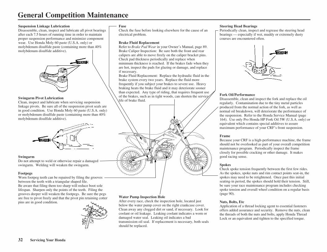
Swingarm Pivot LubricationClean, inspect and lubricate when servicing suspension linkage pivots. Be sure all of the suspension pivot seals are in good condition. Use Honda Moly 60 paste (U.S.A. only) or molybdenum disulfide paste (containing more than 40% molybdenum disulfide additive).
SwingarmDo not attempt to weld or otherwise repair a damaged swingarm. Welding will weaken the swingarm.
FootpegsWorn footpeg teeth can be repaired by filing the grooves between the teeth with a triangular shaped file. Be aware that filing them too sharp will reduce boot sole lifespan. Sharpen only the points of the teeth. Filing the grooves deeper will weaken the footpegs. Be sure the pegs are free to pivot freely and that the pivot pin retaining cotter pins are in good condition.
FuseCheck the fuse before looking elsewhere for the cause of an electrical problem.
Brake Fluid ReplacementRefer to Brake Pad Wear in your Owner’s Manual, page 89. Brake Caliper Inspection: Be sure both the front and rear calipers are able to move freely on the caliper bracket pins. Check pad thickness periodically and replace when minimum thickness is reached. If the brakes fade when they are hot, inspect the pads for glazing or damage, and replace if necessary. Brake Fluid Replacement: Replace the hydraulic fluid in the brake system every two years. Replace the fluid more frequently if you subject your brakes to severe use. Heavy braking heats the brake fluid and it may deteriorate sooner than expected. Any type of riding, that requires frequent use of the brakes, such as in tight woods, can shorten the service life of brake fluid.
Steering Head BearingsPeriodically clean, inspect and regrease the steering head bearings — especially if wet, muddy or extremely dusty courses are encountered often.
Water Pump Inspection HoleAfter every race, check the inspection hole, located just below the water pump cover on the right crankcase cover. Clean away any clogged dirt or sand, if necessary. Look for coolant or oil leakage. Leaking coolant indicates a worn or damaged water seal. Leaking oil indicates a bad transmission oil seal. If replacement is necessary, both seals should be replaced.
Fork Oil/PerformanceDisassemble, clean and inspect the fork and replace the oil regularly. Contamination due to the tiny metal particles produced from the normal action of the fork, as well as normal oil breakdown, will deteriorate the performance of the suspension. Refer to the Honda Service Manual (page 164). Use only Pro Honda HP Fork Oil 5W (U.S.A. only) or equivalent which contains special additives to assure maximum performance of your CRF’s front suspension.
FrameBecause your CRF is a high-performance machine, the frame should not be overlooked as part of your overall competition maintenance program. Periodically inspect the frame closely for possible cracking or other damage. It makes good racing sense.
SpokesCheck spoke tension frequently between the first few rides. As the spokes, spoke nuts and rim contact points seat-in, the spokes may need to be retightened. Once past this initial seating-in period, the spokes should hold their tension. Still, be sure your race maintenance program includes checking spoke tension and overall wheel condition on a regular basis (page 90). Nuts, Bolts, EtcApplication of a thread locking agent to essential fasteners offers added assurance and security. Remove the nuts, clean the threads of both the nuts and bolts, apply Honda Thread Lock or an equivalent and tighten to the specified torque.
Suspension Linkage LubricationDisassemble, clean, inspect and lubricate all pivot bearings after each 7.5 hours of running time in order to maintain proper suspension performance and minimize component wear. Use Honda Moly 60 paste (U.S.A. only) or molybdenum disulfide paste (containing more than 40% molybdenum disulfide additive).
General Competition Maintenance
32 Servicing Your Honda
Before & After Competition Maintenance
Between Motos & Practice Maintenance
After practice or between motos you have achance to make additional checks and adjustments.
• Clean accumulated dirt from under the fenders and off the wheels, suspension components, hand grips, controls, and footpegs. A stiff, nylon parts cleaning brushworks well.
• Check tire air pressure. • Check spoke tension and rim lock nut security.• Check sprocket bolt and nut security.
• Clean the sides of the drive chain with a stiff,nylon parts-cleaning brush. Lubricate andadjust the chain as necessary.
Do not perform maintenance while engine isrunning. Injury to your fingers or hands mayresult.
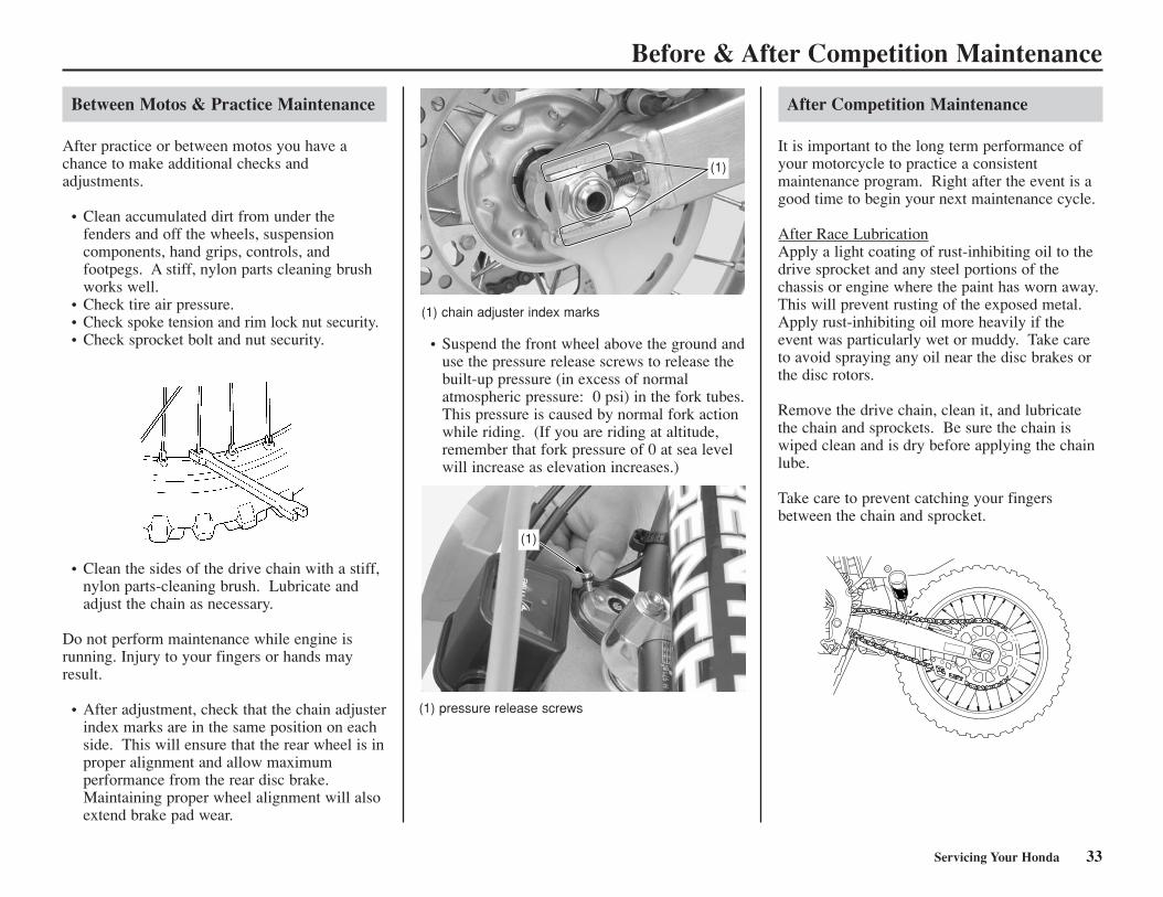
• After adjustment, check that the chain adjusterindex marks are in the same position on eachside. This will ensure that the rear wheel is inproper alignment and allow maximumperformance from the rear disc brake.Maintaining proper wheel alignment will alsoextend brake pad wear.
(1) chain adjuster index marks
• Suspend the front wheel above the ground anduse the pressure release screws to release thebuilt-up pressure (in excess of normal atmospheric pressure: 0 psi) in the fork tubes.This pressure is caused by normal fork actionwhile riding. (If you are riding at altitude,remember that fork pressure of 0 at sea levelwill increase as elevation increases.)
(1) pressure release screws
(1)
(1)
After Competition Maintenance
It is important to the long term performance ofyour motorcycle to practice a consistent maintenance program. Right after the event is agood time to begin your next maintenance cycle.
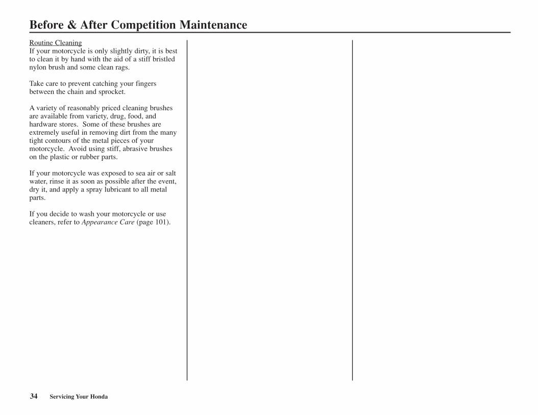
After Race LubricationApply a light coating of rust-inhibiting oil to thedrive sprocket and any steel portions of the chassis or engine where the paint has worn away.This will prevent rusting of the exposed metal.Apply rust-inhibiting oil more heavily if theevent was particularly wet or muddy. Take careto avoid spraying any oil near the disc brakes orthe disc rotors.
Remove the drive chain, clean it, and lubricatethe chain and sprockets. Be sure the chain iswiped clean and is dry before applying the chainlube.
Take care to prevent catching your fingersbetween the chain and sprocket.
Servicing Your Honda 33
Before & After Competition MaintenanceRoutine CleaningIf your motorcycle is only slightly dirty, it is bestto clean it by hand with the aid of a stiff bristlednylon brush and some clean rags.
Take care to prevent catching your fingersbetween the chain and sprocket.
A variety of reasonably priced cleaning brushesare available from variety, drug, food, and hardware stores. Some of these brushes areextremely useful in removing dirt from the manytight contours of the metal pieces of your motorcycle. Avoid using stiff, abrasive brusheson the plastic or rubber parts.
If your motorcycle was exposed to sea air or saltwater, rinse it as soon as possible after the event,dry it, and apply a spray lubricant to all metalparts.
If you decide to wash your motorcycle or usecleaners, refer to Appearance Care (page 101).
34 Servicing Your Honda
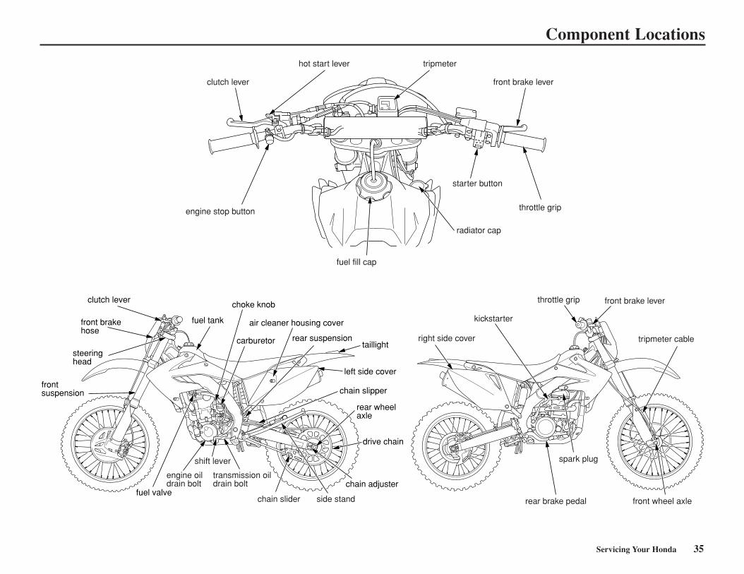
Component Locations
choke knob
carburetor
air cleaner housing cover
rear suspensiontaillight
left side cover
chain slipper
rear wheelaxle
drive chain
chain adjuster
fuel tank
fuel valve
frontsuspension
steeringhead
front brakehose
clutch lever
shift lever
transmission oil drain bolt
engine oil drain bolt
side standchain slider
kickstarter
throttle grip front brake lever
tripmeter cableright side cover
rear brake pedal
spark plug
front wheel axle
clutch lever
hot start lever
front brake lever
engine stop button
fuel fill cap
throttle grip
radiator cap
tripmeter
starter button
Servicing Your Honda 35
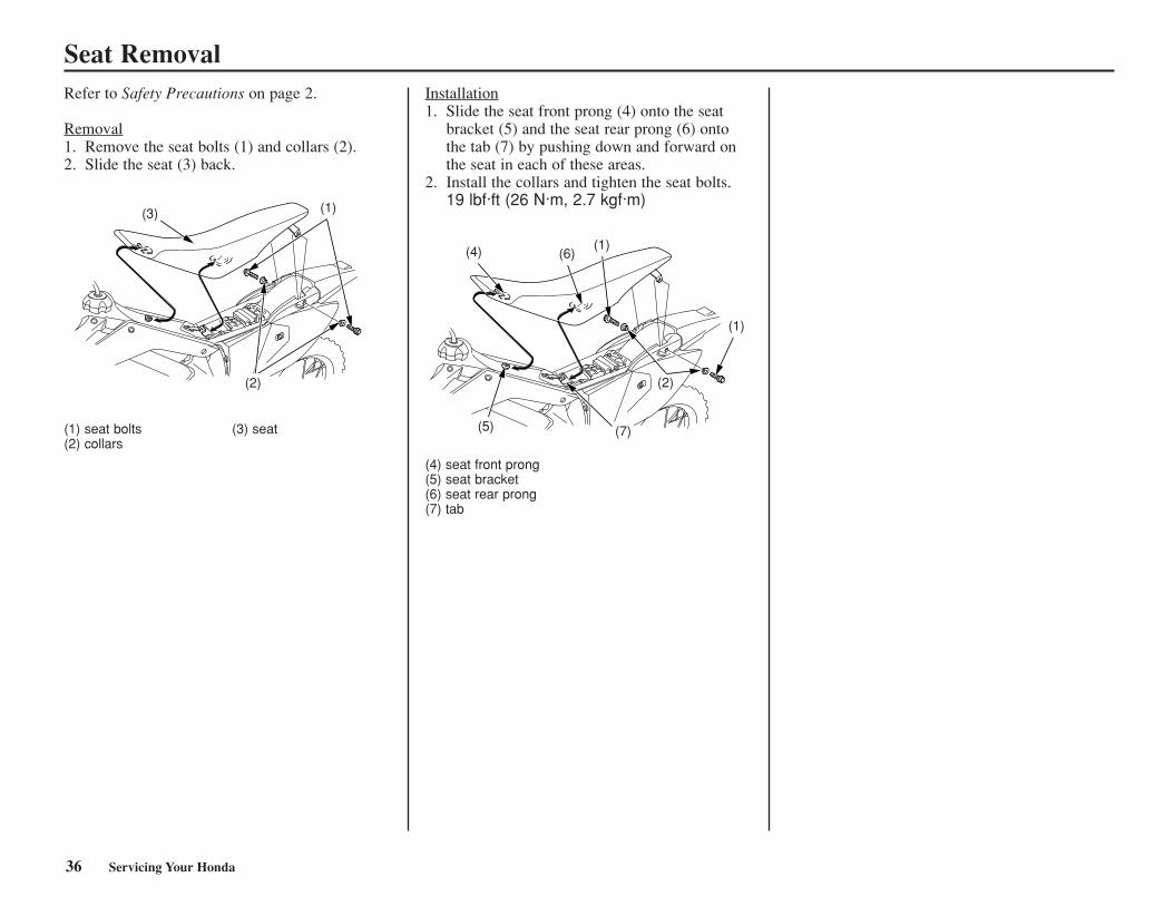
Seat RemovalRefer to Safety Precautions on page 2.
Removal1. Remove the seat bolts (1) and collars (2).2. Slide the seat (3) back.
(1) seat bolts (3) seat(2) collars
Installation1. Slide the seat front prong (4) onto the seat
bracket (5) and the seat rear prong (6) ontothe tab (7) by pushing down and forward onthe seat in each of these areas.
2. Install the collars and tighten the seat bolts.19 lbf·ft (26 N·m, 2.7 kgf·m)
(4) seat front prong(5) seat bracket(6) seat rear prong(7) tab
(3) (1)
(2)
(4) (6)
(7)(5)
(1)
(1)
(2)
36 Servicing Your Honda
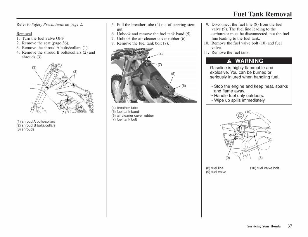
Fuel Tank RemovalRefer to Safety Precautions on page 2.
Removal1. Turn the fuel valve OFF.2. Remove the seat (page 36).3. Remove the shroud A bolts/collars (1).4. Remove the shroud B bolts/collars (2) and
shrouds (3).
(1) shroud A bolts/collars(2) shroud B bolts/collars(3) shrouds
5. Pull the breather tube (4) out of steering stemnut.
6. Unhook and remove the fuel tank band (5).7. Unhook the air cleaner cover rubber (6).8. Remove the fuel tank bolt (7).
(4) breather tube(5) fuel tank band(6) air cleaner cover rubber(7) fuel tank bolt
9. Disconnect the fuel line (8) from the fuelvalve (9). The fuel line leading to the carburetor must be disconnected, not the fuelline leading to the fuel tank.
(8) fuel line (10) fuel valve bolt(9) fuel valve
WARNINGGasoline is highly flammable and explosive. You can be burned orseriously injured when handling fuel.
• Stop the engine and keep heat, sparksand flame away.
• Handle fuel only outdoors.• Wipe up spills immediately.
(3)(2)
(1)
(4)
(7)
(5)
(6)
(9) (8)
(10)
Servicing Your Honda 37
10. Remove the fuel valve bolt (10) and fuelvalve.
11. Remove the fuel tank.
Fuel Tank Removal
(2)
(1) (3)
(7)
(8)(9)
(10)
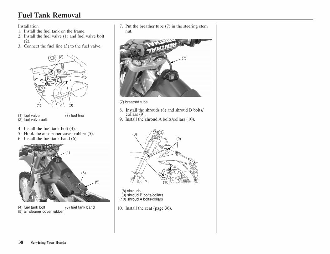
Installation1. Install the fuel tank on the frame.2. Install the fuel valve (1) and fuel valve bolt
(2).3. Connect the fuel line (3) to the fuel valve.
(1) fuel valve (3) fuel line(2) fuel valve bolt
4. Install the fuel tank bolt (4).5. Hook the air cleaner cover rubber (5).6. Install the fuel tank band (6).
7. Put the breather tube (7) in the steering stemnut.
(7) breather tube
8. Install the shrouds (8) and shroud B bolts/collars (9).
9. Install the shroud A bolts/collars (10).
(8) shrouds(9) shroud B bolts/collars
(10) shroud A bolts/collars
(4) fuel tank bolt (6) fuel tank band (5) air cleaner cover rubber
38 Servicing Your Honda
(4)
(6)
(5)
10. Install the seat (page 36).
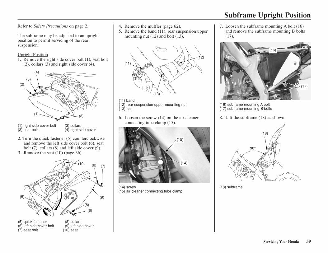
Subframe Upright PositionRefer to Safety Precautions on page 2.
The subframe may be adjusted to an uprightposition to permit servicing of the rearsuspension.
Upright Position1. Remove the right side cover bolt (1), seat bolt
(2), collars (3) and right side cover (4).
4. Remove the muffler (page 62).5. Remove the band (11), rear suspension upper
mounting nut (12) and bolt (13).
(11) band(12) rear suspension upper mounting nut(13) bolt
6. Loosen the screw (14) on the air cleanerconnecting tube clamp (15).
(14) screw(15) air cleaner connecting tube clamp
Servicing Your Honda 39
7. Loosen the subframe mounting A bolt (16)and remove the subframe mounting B bolts(17).
(16) subframe mounting A bolt(17) subframe mounting B bolts
8. Lift the subframe (18) as shown.
(1) right side cover bolt (3) collars(2) seat bolt (4) right side cover
2. Turn the quick fastener (5) counterclockwiseand remove the left side cover bolt (6), seatbolt (7), collars (8) and left side cover (9).
3. Remove the seat (10) (page 36).
(2)
(1) (3)
(3)
(4)
(5)
(8)
(6)
(9)
(7)(8)(10)
(11)
(13)
(12)
(15)
(14)
(16)
(17)
90°
(18)
(18) subframe
(5) quick fastener (8) collars(6) left side cover bolt (9) left side cover(7) seat bolt (10) seat
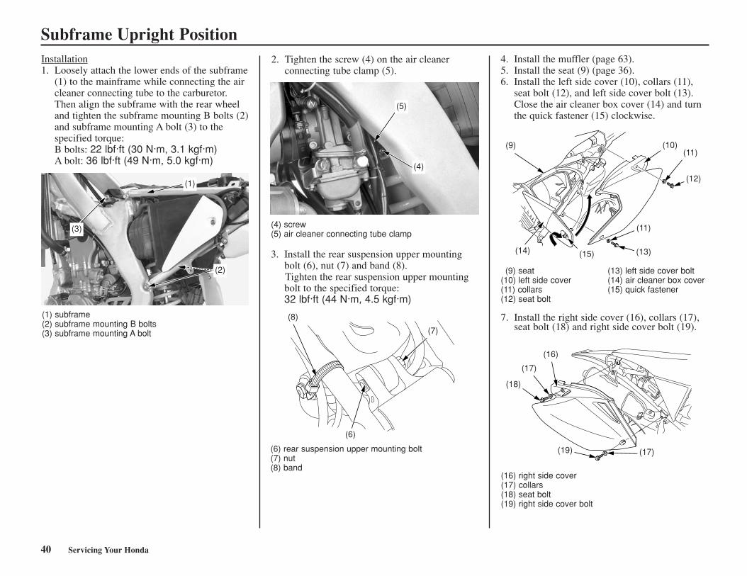
Subframe Upright Position2. Tighten the screw (4) on the air cleaner
connecting tube clamp (5).4. Install the muffler (page 63).5. Install the seat (9) (page 36).6. Install the left side cover (10), collars (11),
seat bolt (12), and left side cover bolt (13).Close the air cleaner box cover (14) and turnthe quick fastener (15) clockwise.
(9) seat (13) left side cover bolt(10) left side cover (14) air cleaner box cover(11) collars (15) quick fastener(12) seat bolt
7. Install the right side cover (16), collars (17),seat bolt (18) and right side cover bolt (19).
(6) rear suspension upper mounting bolt(7) nut(8) band
(1) subframe(2) subframe mounting B bolts(3) subframe mounting A bolt
Installation1. Loosely attach the lower ends of the subframe
(1) to the mainframe while connecting the aircleaner connecting tube to the carburetor.Then align the subframe with the rear wheeland tighten the subframe mounting B bolts (2)and subframe mounting A bolt (3) to thespecified torque:B bolts: 22 lbf·ft (30 N·m, 3.1 kgf·m)A bolt: 36 lbf·ft (49 N·m, 5.0 kgf·m)
40 Servicing Your Honda
(3)
(1)
(2)
(5)
(4)
(4) screw(5) air cleaner connecting tube clamp
3. Install the rear suspension upper mountingbolt (6), nut (7) and band (8).Tighten the rear suspension upper mountingbolt to the specified torque:32 lbf·ft (44 N·m, 4.5 kgf·m)
(8)
(7)
(6)
(9)
(14) (15) (13)
(11)
(12)
(11)(10)
(18)
(19) (17)
(17)
(16)
(16) right side cover(17) collars(18) seat bolt(19) right side cover bolt
Fuel SystemRefer to Safety Precautions on page 2.
Fuel Recommendation
We recommend that you use unleaded fuelbecause it produces fewer engine deposits andextends the life of exhaust system components.
Your engine is designed to use any gasoline thathas a pump octane number of 91 or higher.Gasoline pumps at service stations normally display the pump octane number. For information on the use of oxygenated fuels, seepage 156.
Use of lower octane gasoline can cause persistent“pinging” or “spark knock” (a louder rappingnoise) which, if severe, can lead to engine damage. (Light pinging experienced while operating under a heavy load, such as climbing ahill, is no cause for concern.)
If pinging or spark knock occurs at a steadyengine speed under normal load, change brandsof gasoline. If pinging or spark knock persists,consult your Honda dealer.
Never use stale or contaminated gasoline. Avoidgetting dirt, dust, or water in the fuel tank.
Type Unleaded
Pump Octane Number 91 (or higher)
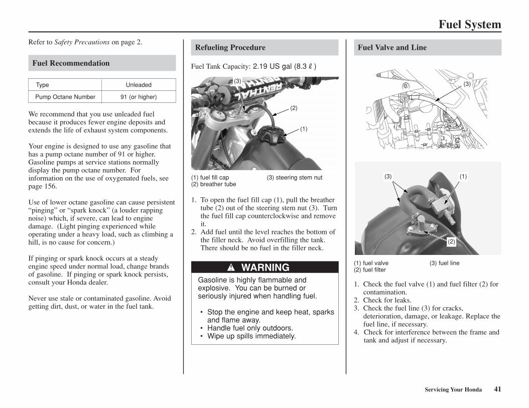
Refueling Procedure
Fuel Tank Capacity: 2.19 US gal (8.3R)
(1) fuel fill cap (3) steering stem nut(2) breather tube
1. To open the fuel fill cap (1), pull the breathertube (2) out of the steering stem nut (3). Turnthe fuel fill cap counterclockwise and removeit.
2. Add fuel until the level reaches the bottom ofthe filler neck. Avoid overfilling the tank.There should be no fuel in the filler neck.
WARNINGGasoline is highly flammable and explosive. You can be burned or seriously injured when handling fuel.
• Stop the engine and keep heat, sparksand flame away.
• Handle fuel only outdoors. • Wipe up spills immediately.
Fuel Valve and Line
(1) fuel valve (3) fuel line(2) fuel filter
1. Check the fuel valve (1) and fuel filter (2) for contamination.
2. Check for leaks. 3. Check the fuel line (3) for cracks,
deterioration, damage, or leakage. Replace thefuel line, if necessary.
4. Check for interference between the frame andtank and adjust if necessary.
(2)
(1)
(3) (3)
(2)
(3) (1)
Servicing Your Honda 41
Fuel System
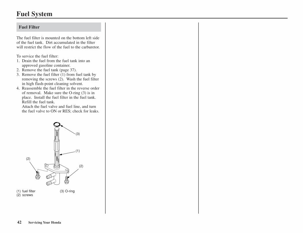
Fuel Filter
The fuel filter is mounted on the bottom left sideof the fuel tank. Dirt accumulated in the filterwill restrict the flow of the fuel to the carburetor.
To service the fuel filter:1. Drain the fuel from the fuel tank into an
approved gasoline container.2. Remove the fuel tank (page 37). 3. Remove the fuel filter (1) from fuel tank by
removing the screws (2). Wash the fuel filterin high flash-point cleaning solvent.
4. Reassemble the fuel filter in the reverse orderof removal. Make sure the O-ring (3) is inplace. Install the fuel filter in the fuel tank. Refill the fuel tank. Attach the fuel valve and fuel line, and turnthe fuel valve to ON or RES; check for leaks.
(1) fuel filter (3) O-ring(2) screws
(2)
(2)
(1)
(3)
42 Servicing Your Honda
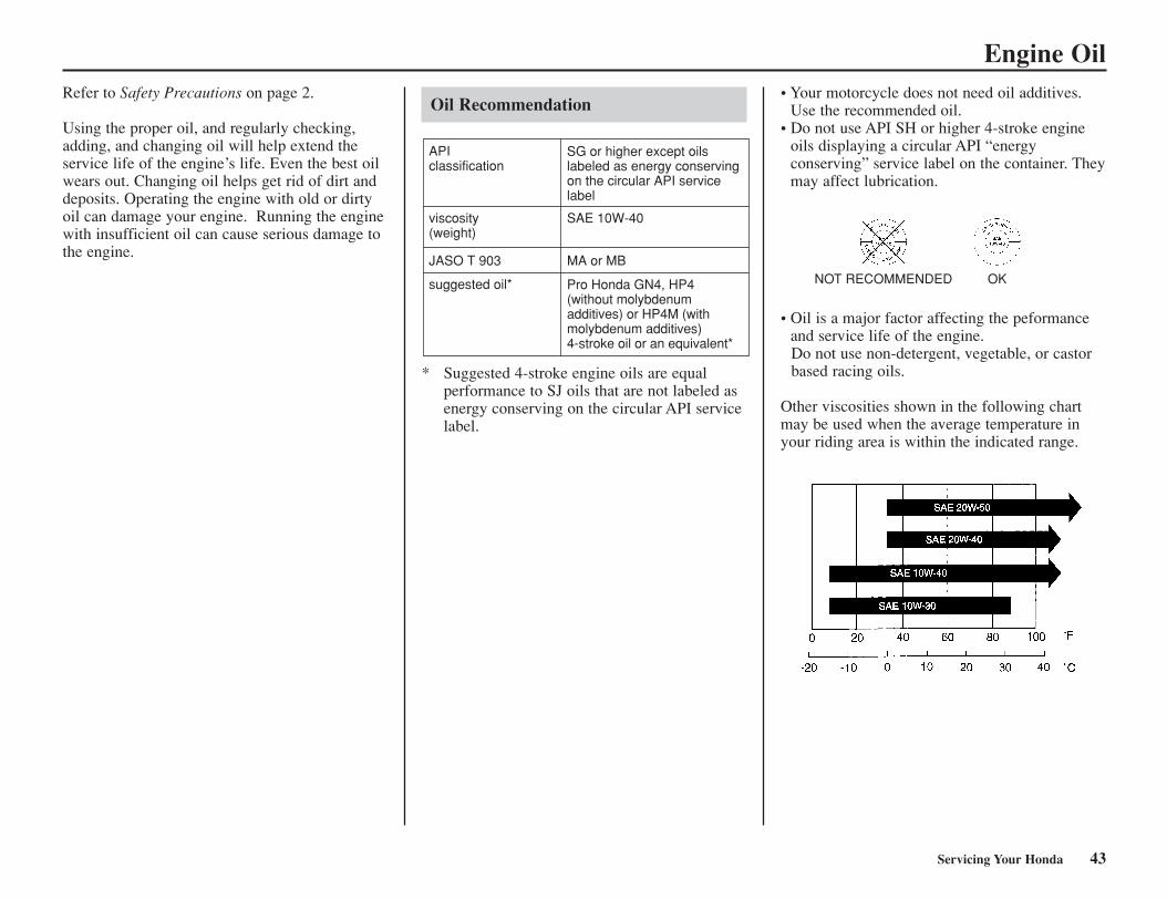
* Suggested 4-stroke engine oils are equalperformance to SJ oils that are not labeled asenergy conserving on the circular API servicelabel.
Engine OilRefer to Safety Precautions on page 2.
Using the proper oil, and regularly checking,adding, and changing oil will help extend theservice life of the engine’s life. Even the best oilwears out. Changing oil helps get rid of dirt anddeposits. Operating the engine with old or dirtyoil can damage your engine. Running the enginewith insufficient oil can cause serious damage tothe engine.
Oil Recommendation
APIclassification
SG or higher except oils labeled as energy conserving on the circular API service label
suggested oil* Pro Honda GN4, HP4 (without molybdenum additives) or HP4M (with molybdenum additives) 4-stroke oil or an equivalent*
viscosity(weight)
SAE 10W-40
JASO T 903 MA or MB
• Your motorcycle does not need oil additives.Use the recommended oil.
• Do not use API SH or higher 4-stroke engineoils displaying a circular API “energy conserving” service label on the container. Theymay affect lubrication.
• Oil is a major factor affecting the peformanceand service life of the engine.Do not use non-detergent, vegetable, or castorbased racing oils.
Other viscosities shown in the following chartmay be used when the average temperature inyour riding area is within the indicated range.
NOT RECOMMENDED OK
Servicing Your Honda 43
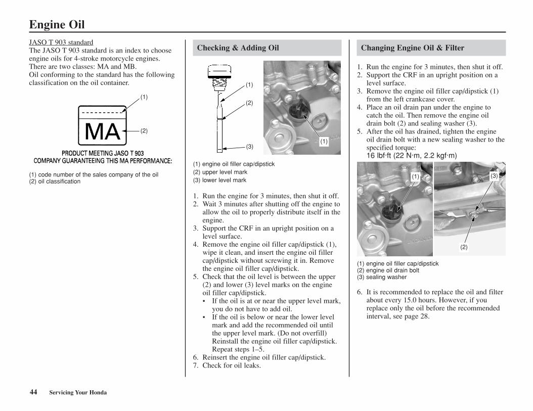
Engine OilJASO T 903 standardThe JASO T 903 standard is an index to chooseengine oils for 4-stroke motorcycle engines.There are two classes: MA and MB.Oil conforming to the standard has the followingclassification on the oil container.
(1) code number of the sales company of the oil(2) oil classification
Checking & Adding Oil
(1) engine oil filler cap/dipstick(2) upper level mark(3) lower level mark
1. Run the engine for 3 minutes, then shut it off. 2. Wait 3 minutes after shutting off the engine to
allow the oil to properly distribute itself in theengine.
3. Support the CRF in an upright position on alevel surface.
4. Remove the engine oil filler cap/dipstick (1),wipe it clean, and insert the engine oil fillercap/dipstick without screwing it in. Removethe engine oil filler cap/dipstick.
5. Check that the oil level is between the upper(2) and lower (3) level marks on the engineoil filler cap/dipstick.• If the oil is at or near the upper level mark,
you do not have to add oil.• If the oil is below or near the lower level
mark and add the recommended oil untilthe upper level mark. (Do not overfill)Reinstall the engine oil filler cap/dipstick.Repeat steps 1–5.
6. Reinsert the engine oil filler cap/dipstick.7. Check for oil leaks.
Changing Engine Oil & Filter
1. Run the engine for 3 minutes, then shut it off. 2. Support the CRF in an upright position on a
level surface. 3. Remove the engine oil filler cap/dipstick (1)
from the left crankcase cover.4. Place an oil drain pan under the engine to
catch the oil. Then remove the engine oildrain bolt (2) and sealing washer (3).
5. After the oil has drained, tighten the engineoil drain bolt with a new sealing washer to thespecified torque:16 lbf·ft (22 N·m, 2.2 kgf·m)
(1) engine oil filler cap/dipstick(2) engine oil drain bolt(3) sealing washer
6. It is recommended to replace the oil and filterabout every 15.0 hours. However, if youreplace only the oil before the recommendedinterval, see page 28.
(2)(2)
(1)
(1)
(2)
(3)(1)
(1) (3)
(2)
44 Servicing Your Honda
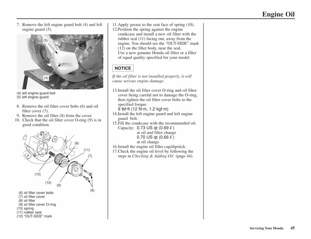
Engine Oil7. Remove the left engine guard bolt (4) and left
engine guard (5).11.Apply grease to the seat face of spring (10).12.Position the spring against the engine
crankcase and install a new oil filter with therubber seal (11) facing out, away from theengine. You should see the ”OUT-SIDE” mark(12) on the filter body, near the seal.Use a new genuine Honda oil filter or a filterof equal quality specified for your model.
If the oil filter is not installed properly, it willcause serious engine damage.
13.Install the oil filter cover O-ring and oil filtercover being careful not to damage the O-ring,then tighten the oil filter cover bolts to thespecified forque:9 lbf·ft (12 N·m, 1.2 kgf·m)
14.Install the left engine guard and left engineguard bolt.
15.Fill the crankcase with the recommended oil.Capacity: 0.73 US qt (0.69R)
at oil and filter change0.70 US qt (0.66R)at oil change
16.Install the engine oil filler cap/dipstick.17.Check the engine oil level by following the
steps in Checking & Adding Oil (page 44).
NOTICE
(4) left engine guard bolt(5) left engine guard
8. Remove the oil filter cover bolts (6) and oilfilter cover (7).
9. Remove the oil filter (8) from the cover.
(6) oil filter cover bolts(7) oil filter cover(8) oil filter(9) oil filter cover O-ring
(10) spring(11) rubber seal(12) “OUT-SIDE” mark
(5)
(4)
(10)
(12)(9)
(8)
(11)
(7)
(6)
Servicing Your Honda 45
10. Check that the oil filter cover O-ring (9) is ingood condition.
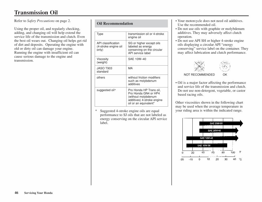
Type
API classification(4-stroke engine oilonly)
Viscosity(weight)
JASO T903standard
others
suggested oil*
Refer to Safety Precautions on page 2.
Using the proper oil, and regularly checking,adding, and changing oil will help extend theservice life of the transmission and clutch. Eventhe best oil wears out. Changing oil helps get ridof dirt and deposits. Operating the engine withold or dirty oil can damage your engine.Running the engine with insufficient oil cancause serious damage to the engine andtransmission.
Oil Recommendation• Your motorcycle does not need oil additives.
Use the recommended oil.• Do not use oils with graphite or molybdenum
additives. They may adversely affect clutchoperation.
• Do not use API SH or higher 4-stroke engineoils displaying a circular API “energy conserving” service label on the container. Theymay affect lubrication and clutch performance.
* Suggested 4-stroke engine oils are equalperformance to SJ oils that are not labeled asenergy conserving on the circular API servicelabel.
transmission oil or 4-strokeengine oil
SG or higher except oilslabeled as energy conserving on the circularAPI service label
SAE 10W–40
MA
without friction modifierssuch as molybdenumadditives
Pro Honda HP Trans oil, Pro Honda GN4 or HP4(without molybdenumadditives) 4-stroke engineoil or an equivalent*
Transmission Oil
• Oil is a major factor affecting the performanceand service life of the transmission and clutch.Do not use non-detergent, vegetable, or castorbased racing oils.
Other viscosities shown in the following chartmay be used when the average temperature inyour riding area is within the indicated range.
NOT RECOMMENDED OK
46 Servicing Your Honda
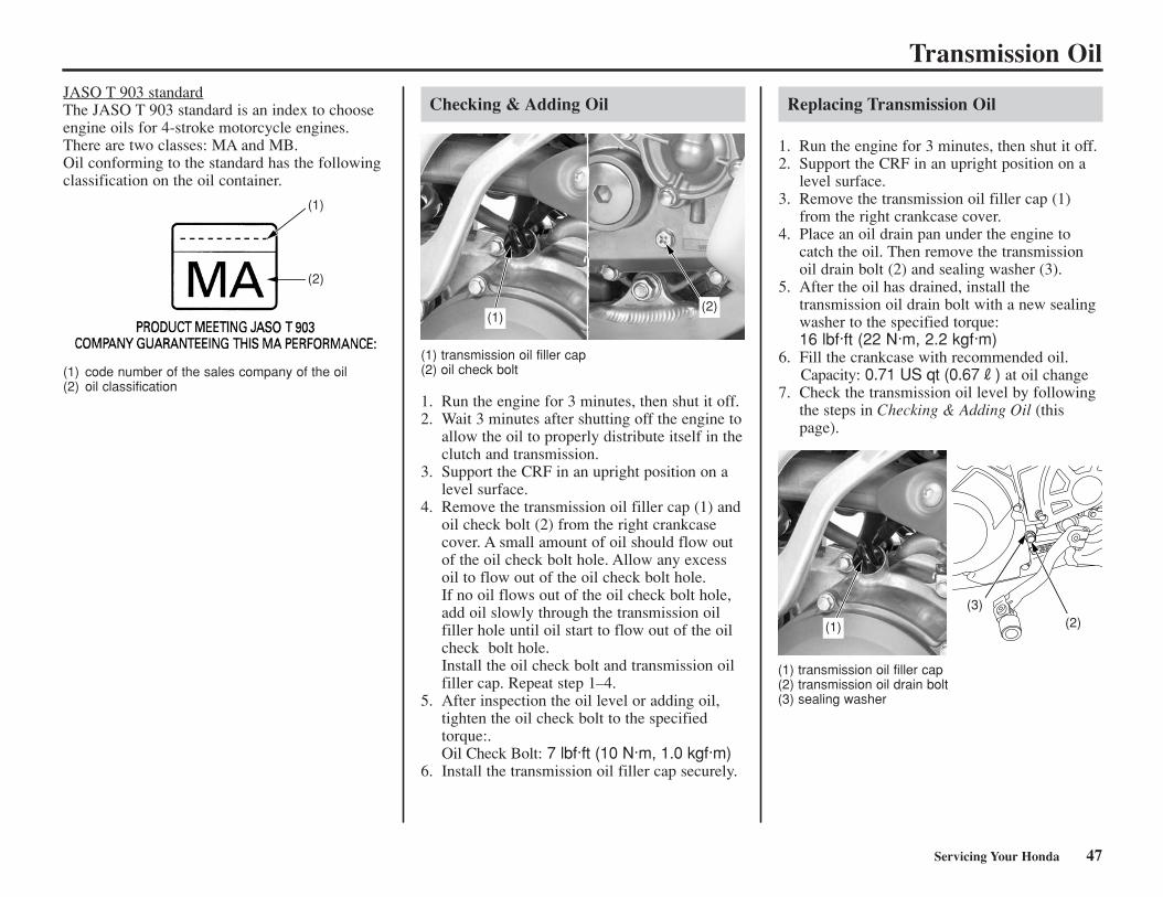
JASO T 903 standardThe JASO T 903 standard is an index to chooseengine oils for 4-stroke motorcycle engines.There are two classes: MA and MB.Oil conforming to the standard has the followingclassification on the oil container.
(1) code number of the sales company of the oil(2) oil classification
Checking & Adding Oil
(1) transmission oil filler cap(2) oil check bolt
1. Run the engine for 3 minutes, then shut it off. 2. Wait 3 minutes after shutting off the engine to
allow the oil to properly distribute itself in theclutch and transmission.
3. Support the CRF in an upright position on alevel surface.
4. Remove the transmission oil filler cap (1) andoil check bolt (2) from the right crankcasecover. A small amount of oil should flow outof the oil check bolt hole. Allow any excessoil to flow out of the oil check bolt hole.If no oil flows out of the oil check bolt hole,add oil slowly through the transmission oilfiller hole until oil start to flow out of the oilcheck bolt hole.Install the oil check bolt and transmission oilfiller cap. Repeat step 1–4.
5. After inspection the oil level or adding oil,tighten the oil check bolt to the specifiedtorque:.Oil Check Bolt: 7 lbf·ft (10 N·m, 1.0 kgf·m)
6. Install the transmission oil filler cap securely.
Replacing Transmission Oil
1. Run the engine for 3 minutes, then shut it off. 2. Support the CRF in an upright position on a
level surface. 3. Remove the transmission oil filler cap (1)
from the right crankcase cover. 4. Place an oil drain pan under the engine to
catch the oil. Then remove the transmissionoil drain bolt (2) and sealing washer (3).
5. After the oil has drained, install thetransmission oil drain bolt with a new sealingwasher to the specified torque:16 lbf·ft (22 N·m, 2.2 kgf·m)
6. Fill the crankcase with recommended oil.Capacity: 0.71 US qt (0.67R) at oil change
7. Check the transmission oil level by followingthe steps in Checking & Adding Oil (thispage).
Transmission Oil
(2)(2)
(1)
(1)(2)
(1)
(3)(2)
(1) transmission oil filler cap(2) transmission oil drain bolt(3) sealing washer
Servicing Your Honda 47
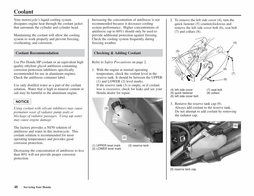
Coolant
48 Servicing Your Honda
Your motorcycle’s liquid cooling system dissipates engine heat through the coolant jacketthat surrounds the cylinder and cylinder head.
Maintaining the coolant will allow the coolingsystem to work properly and prevent freezing,overheating, and corrosion.
Coolant Recommendation
Use Pro Honda HP coolant or an equivalent highquality ethylene glycol antifreeze containing corrosion protection inhibitors specifically recommended for use in aluminum engines.Check the antifreeze container label.
Use only distilled water as a part of the coolantsolution. Water that is high in mineral content orsalt may be harmful to the aluminum engine.
Using coolant with silicate inhibitors may causepremature wear of radiator pump seals or blockage of radiator passages. Using tap watermay cause engine damage.
The factory provides a 50/50 solution ofantifreeze and water in this motorcycle. Thiscoolant solution is recommended for most operating temperatures and provides goodcorrosion protection.
Decreasing the concentration of antifreeze to lessthan 40% will not provide proper corrosion protection.
NOTICE
Increasing the concentration of antifreeze is notrecommended because it decreases cooling system performance. Higher concentrations ofantifreeze (up to 60%) should only be used toprovide additional protection against freezing.Check the cooling system frequently duringfreezing weather.
Checking & Adding Coolant
Refer to Safety Precautions on page 2.
1. With the engine at normal operatingtemperature, check the coolant level in thereserve tank. It should be between the UPPER(1) and LOWER (2) level marks.If the reserve tank (3) is empty, or if coolantloss is excessive, check for leaks and see yourHonda dealer for repair.
(1) UPPER level mark (3) reserve tank(2) LOWER level mark
2. To remove the left side cover (4), turn thequick fastener (5) counterclockwise andremove the left side cover bolt (6), seat bolt(7) and collars (8).
(4) left side cover (7) seat bolt (5) quick fastener (8) collars(6) left side cover bolt
3. Remove the reserve tank cap (9).Always add coolant to the reserve tank.Do not attempt to add coolant by removingthe radiator cap.
(9) reserve tank cap
(3)
(1)
(2)
(5)
(4)
(7)
(6)
(8)
(9)
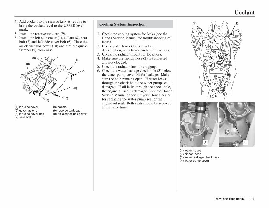
Coolant
(4) left side cover (8) collars(5) quick fastener (9) reserve tank cap(6) left side cover bolt (10) air cleaner box cover(7) seat bolt
Servicing Your Honda 49
4. Add coolant to the reserve tank as require tobring the coolant level to the UPPER levelmark.
5. Install the reserve tank cap (9).6. Install the left side cover (4), collars (8), seat
bolt (7) and left side cover bolt (6). Close theair cleaner box cover (10) and turn the quickfastener (5) clockwise.
Cooling System Inspection
1. Check the cooling system for leaks (see theHonda Service Manual for troubleshooting ofleaks).
2. Check water hoses (1) for cracks,deterioration, and clamp bands for looseness.
3. Check the radiator mount for looseness. 4. Make sure the siphon hose (2) is connected
and not clogged. 5. Check the radiator fins for clogging. 6. Check the water leakage check hole (3) below
the water pump cover (4) for leakage. Makesure the hole remains open. If water leaksthrough the check hole, the water pump seal isdamaged. If oil leaks through the check hole,the engine oil seal is damaged. See the HondaService Manual or consult your Honda dealerfor replacing the water pump seal or theengine oil seal. Both seals should be replacedat the same time.
(1) water hoses(2) siphon hose(3) water leakage check hole(4) water pump cover
(10)
(9)(4)
(7)
(8)
(6)(5)
(1) (2)
(3)(4)
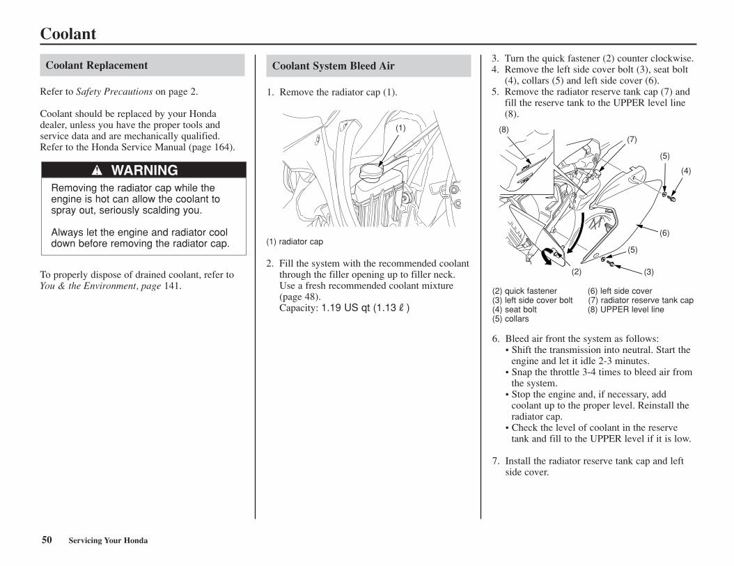
Coolant Replacement
Refer to Safety Precautions on page 2.
Coolant should be replaced by your Honda dealer, unless you have the proper tools and service data and are mechanically qualified.Refer to the Honda Service Manual (page 164).
Coolant
WARNINGRemoving the radiator cap while theengine is hot can allow the coolant tospray out, seriously scalding you.
Always let the engine and radiator cooldown before removing the radiator cap.
50 Servicing Your Honda
To properly dispose of drained coolant, refer toYou & the Environment, page 141.
Coolant System Bleed Air
1. Remove the radiator cap (1).
(1) radiator cap
2. Fill the system with the recommended coolantthrough the filler opening up to filler neck.Use a fresh recommended coolant mixture(page 48).Capacity: 1.19 US qt (1.13R)
3. Turn the quick fastener (2) counter clockwise.4. Remove the left side cover bolt (3), seat bolt
(4), collars (5) and left side cover (6).5. Remove the radiator reserve tank cap (7) and
fill the reserve tank to the UPPER level line(8).
(2) quick fastener (6) left side cover(3) left side cover bolt (7) radiator reserve tank cap(4) seat bolt (8) UPPER level line(5) collars
6. Bleed air front the system as follows:• Shift the transmission into neutral. Start the
engine and let it idle 2-3 minutes.• Snap the throttle 3-4 times to bleed air from
the system.• Stop the engine and, if necessary, add
coolant up to the proper level. Reinstall theradiator cap.
• Check the level of coolant in the reservetank and fill to the UPPER level if it is low.
7. Install the radiator reserve tank cap and leftside cover.
(1) (8)(7)
(5)
(4)
(6)
(5)
(2) (3)
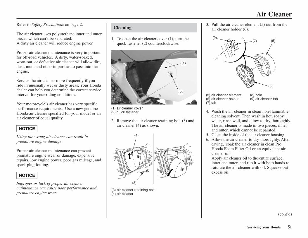
Air CleanerRefer to Safety Precautions on page 2.
The air cleaner uses polyurethane inner and outerpieces which can’t be separated. A dirty air cleaner will reduce engine power.
Proper air cleaner maintenance is very importantfor off-road vehicles. A dirty, water-soaked,worn-out, or defective air cleaner will allow dirt,dust, mud, and other impurities to pass into theengine.
Service the air cleaner more frequently if youride in unusually wet or dusty areas. Your Hondadealer can help you determine the correct serviceinterval for your riding conditions.
Your motorcycle’s air cleaner has very specificperformance requirements. Use a new genuineHonda air cleaner specified for your model or anair cleaner of equal quality.
Using the wrong air cleaner can result in premature engine damage.
Proper air cleaner maintenance can prevent premature engine wear or damage, expensiverepairs, low engine power, poor gas mileage, andspark plug fouling.
Improper or lack of proper air cleaner maintenance can cause poor performance andpremature engine wear.
NOTICE
NOTICE
Cleaning
1. To open the air cleaner cover (1), turn thequick fastener (2) counterclockwise.
3. Pull the air cleaner element (5) out from theair cleaner holder (6).
(1) air cleaner cover(2) quick fastener
2. Remove the air cleaner retaining bolt (3) andair cleaner (4) as shown.
(5) air cleaner element (8) hole(6) air cleaner holder (9) air cleaner tab(7) tab
4. Wash the air cleaner in clean non-flammablecleaning solvent. Then wash in hot, soapywater, rinse well, and allow to dry thoroughly. The air cleaner is made in two pieces: innerand outer, which cannot be separated.
5. Clean the inside of the air cleaner housing.6. Allow the air cleaner to dry thoroughly. After
drying, soak the air cleaner in clean ProHonda Foam Filter Oil or an equivalent aircleaner oil. Apply air cleaner oil to the entire surface,inner and outer, and rub it with both hands tosaturate the air cleaner with oil. Squeeze outexcess oil.
(cont’d)
(3) air cleaner retaining bolt(4) air cleaner
Servicing Your Honda 51
(1)
(2)
(4)
(3)
(9)(7) (5)
(6)
(8)
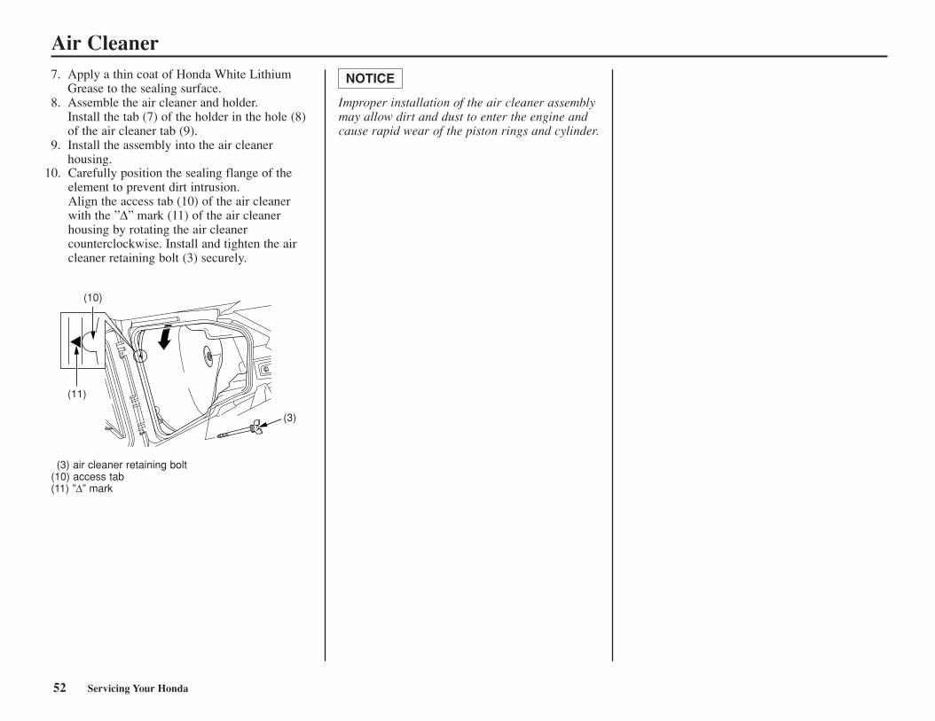
Air Cleaner
Improper installation of the air cleaner assemblymay allow dirt and dust to enter the engine andcause rapid wear of the piston rings and cylinder.
NOTICE7. Apply a thin coat of Honda White LithiumGrease to the sealing surface.
8. Assemble the air cleaner and holder. Install the tab (7) of the holder in the hole (8)of the air cleaner tab (9).
9. Install the assembly into the air cleanerhousing.
(3) air cleaner retaining bolt(10) access tab(11) ”∆” mark
52 Servicing Your Honda
(10)
(11)
(3)
10. Carefully position the sealing flange of theelement to prevent dirt intrusion.Align the access tab (10) of the air cleanerwith the ”∆” mark (11) of the air cleanerhousing by rotating the air cleanercounterclockwise. Install and tighten the aircleaner retaining bolt (3) securely.
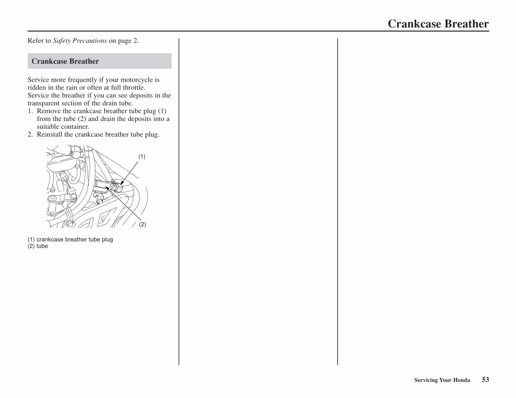
Crankcase Breather
Servicing Your Honda 53
Refer to Safety Precautions on page 2.
Crankcase Breather
Service more frequently if your motorcycle isridden in the rain or often at full throttle.Service the breather if you can see deposits in thetransparent section of the drain tube.1. Remove the crankcase breather tube plug (1)
from the tube (2) and drain the deposits into asuitable container.
2. Reinstall the crankcase breather tube plug.
(1) crankcase breather tube plug(2) tube
(2)
(1)
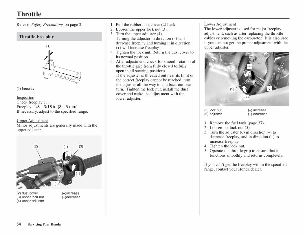
ThrottleRefer to Safety Precautions on page 2.
Throttle Freeplay
(1) freeplay
InspectionCheck freeplay (1).Freeplay: 1/8 - 3/16 in (3 - 5 mm)If necessary, adjust to the specified range.
Upper AdjustmentMinor adjustments are generally made with theupper adjuster.
Lower AdjustmentThe lower adjuster is used for major freeplayadjustment, such as after replacing the throttlecables or removing the carburetor. It is also usedif you can not get the proper adjustment with theupper adjuster.(1)
(2) (3)
(4)
(+)
(–)
(5) lock nut (+) increase (6) adjuster (–) decrease
1. Remove the fuel tank (page 37).2. Loosen the lock nut (5).3. Turn the adjuster (6) in direction (–) to
decrease freeplay, and in direction (+) toincrease freeplay.
4. Tighten the lock nut.5. Operate the throttle grip to ensure that it
functions smoothly and returns completely.
If you can’t get the freeplay within the specifiedrange, contact your Honda dealer.
(5) (6)
(+)
(–)
1. Pull the rubber dust cover (2) back.2. Loosen the upper lock nut (3).3. Turn the upper adjuster (4).
Turning the adjuster in direction (–) willdecrease freeplay and turning it in direction(+) will increase freeplay.
4. Tighten the lock nut. Return the dust cover toits normal position.
5. After adjustment, check for smooth rotation ofthe throttle grip from fully closed to fullyopen in all steering positions.If the adjuster is threaded out near its limit orthe correct freeplay cannot be reached, turnthe adjuster all the way in and back out oneturn. Tighten the lock nut, install the dustcover and make the adjustment with the lower adjuster.
(2) dust cover (+)increase(3) upper lock nut (–)decrease(4) upper adjuster
54 Servicing Your Honda
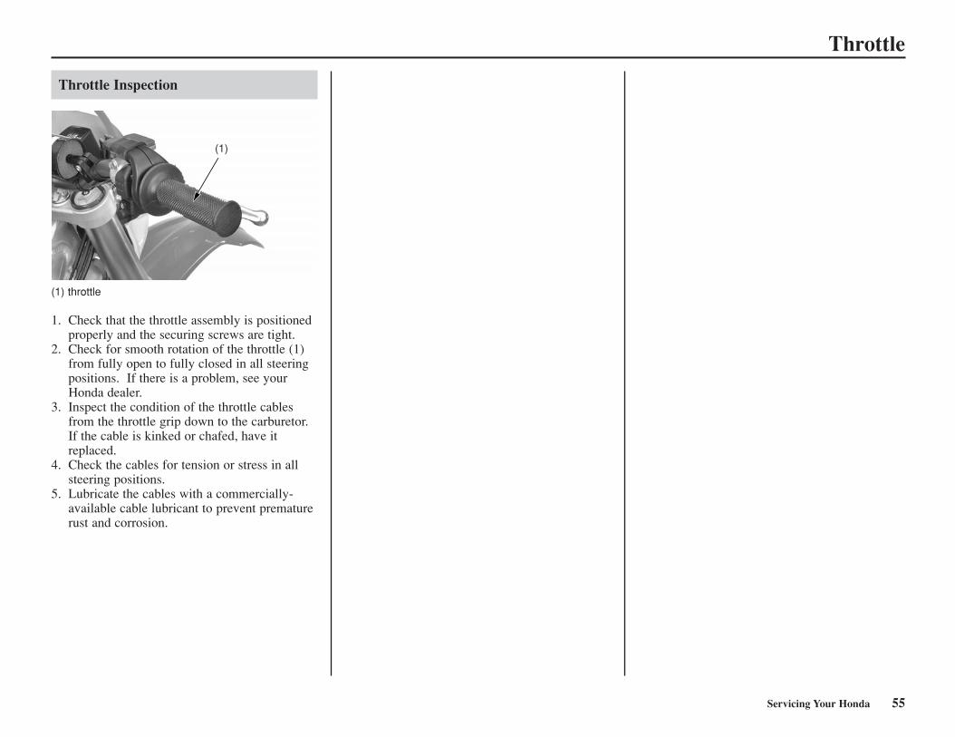
Throttle
Throttle Inspection
(1) throttle
1. Check that the throttle assembly is positionedproperly and the securing screws are tight.
2. Check for smooth rotation of the throttle (1)from fully open to fully closed in all steeringpositions. If there is a problem, see yourHonda dealer.
3. Inspect the condition of the throttle cablesfrom the throttle grip down to the carburetor.If the cable is kinked or chafed, have itreplaced.
4. Check the cables for tension or stress in allsteering positions.
5. Lubricate the cables with a commercially-available cable lubricant to prevent prematurerust and corrosion.
(1)
Servicing Your Honda 55
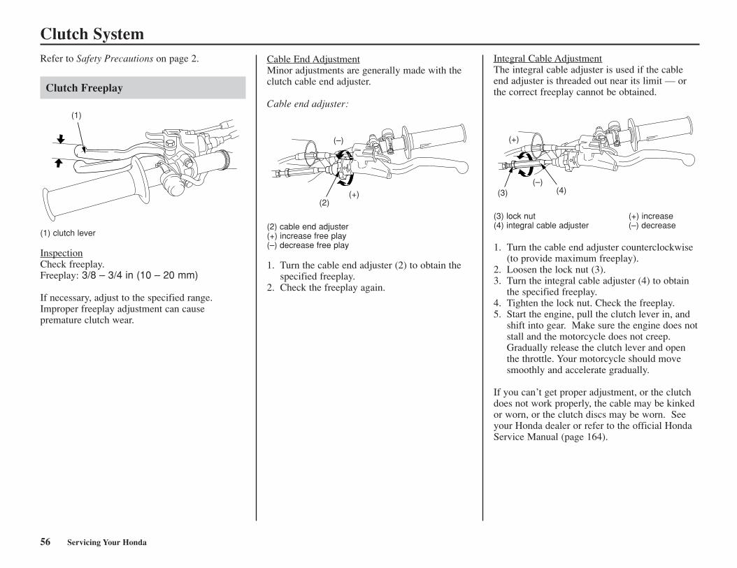
Clutch SystemRefer to Safety Precautions on page 2.
Clutch Freeplay
Cable End AdjustmentMinor adjustments are generally made with theclutch cable end adjuster.
Cable end adjuster:
(2) cable end adjuster(+) increase free play(–) decrease free play
1. Turn the cable end adjuster (2) to obtain thespecified freeplay.
2. Check the freeplay again.
Integral Cable AdjustmentThe integral cable adjuster is used if the cableend adjuster is threaded out near its limit — orthe correct freeplay cannot be obtained.
(3) lock nut (+) increase(4) integral cable adjuster (–) decrease
1. Turn the cable end adjuster counterclockwise(to provide maximum freeplay).
2. Loosen the lock nut (3).3. Turn the integral cable adjuster (4) to obtain
the specified freeplay.4. Tighten the lock nut. Check the freeplay.5. Start the engine, pull the clutch lever in, and
shift into gear. Make sure the engine does notstall and the motorcycle does not creep.Gradually release the clutch lever and openthe throttle. Your motorcycle should movesmoothly and accelerate gradually.
If you can’t get proper adjustment, or the clutchdoes not work properly, the cable may be kinkedor worn, or the clutch discs may be worn. Seeyour Honda dealer or refer to the official HondaService Manual (page 164).
(1) clutch lever
InspectionCheck freeplay.Freeplay: 3/8 – 3/4 in (10 – 20 mm)
If necessary, adjust to the specified range.Improper freeplay adjustment can cause premature clutch wear.
56 Servicing Your Honda
(1)
(–)
(+)(2)
(+)
(–)(3) (4)
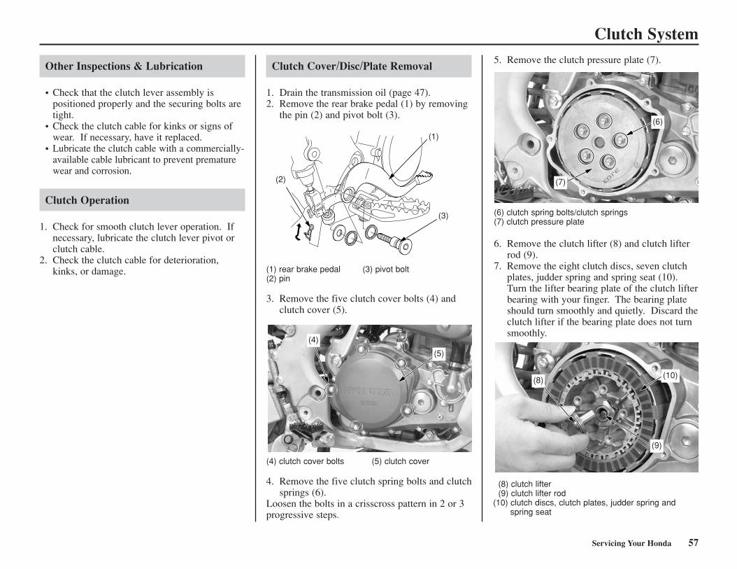
Clutch System
Other Inspections & Lubrication
• Check that the clutch lever assembly is positioned properly and the securing bolts aretight.
• Check the clutch cable for kinks or signs ofwear. If necessary, have it replaced.
• Lubricate the clutch cable with a commercially-available cable lubricant to prevent prematurewear and corrosion.
Clutch Operation
1. Check for smooth clutch lever operation. Ifnecessary, lubricate the clutch lever pivot orclutch cable.
2. Check the clutch cable for deterioration,kinks, or damage.
Clutch Cover/Disc/Plate Removal
1. Drain the transmission oil (page 47).2. Remove the rear brake pedal (1) by removing
the pin (2) and pivot bolt (3).
Servicing Your Honda 57
(1) rear brake pedal (3) pivot bolt(2) pin
3. Remove the five clutch cover bolts (4) andclutch cover (5).
(4) clutch cover bolts (5) clutch cover
4. Remove the five clutch spring bolts and clutchsprings (6).
Loosen the bolts in a crisscross pattern in 2 or 3progressive steps.
5. Remove the clutch pressure plate (7).
(6) clutch spring bolts/clutch springs(7) clutch pressure plate
6. Remove the clutch lifter (8) and clutch lifterrod (9).
7. Remove the eight clutch discs, seven clutchplates, judder spring and spring seat (10).Turn the lifter bearing plate of the clutch lifterbearing with your finger. The bearing plateshould turn smoothly and quietly. Discard theclutch lifter if the bearing plate does not turnsmoothly.
(8) clutch lifter(9) clutch lifter rod
(10) clutch discs, clutch plates, judder spring andspring seat
(2)
(1)
(3)
(4)
(5)
(7)
(6)
(8)
(9)
(10)
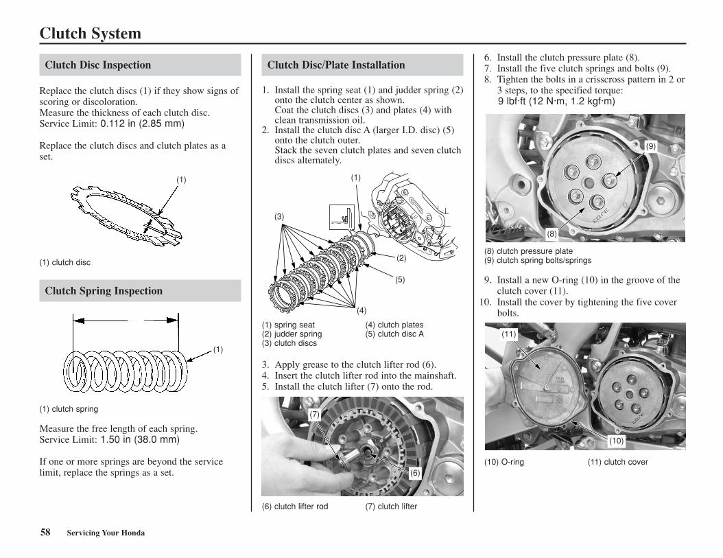
Clutch System
Clutch Disc Inspection
Replace the clutch discs (1) if they show signs ofscoring or discoloration.Measure the thickness of each clutch disc.Service Limit: 0.112 in (2.85 mm)
Replace the clutch discs and clutch plates as aset.
(1) clutch disc
Clutch Spring Inspection
(1) clutch spring
Measure the free length of each spring.Service Limit: 1.50 in (38.0 mm)
If one or more springs are beyond the servicelimit, replace the springs as a set.
Clutch Disc/Plate Installation
1. Install the spring seat (1) and judder spring (2)onto the clutch center as shown.Coat the clutch discs (3) and plates (4) withclean transmission oil.
2. Install the clutch disc A (larger I.D. disc) (5)onto the clutch outer.Stack the seven clutch plates and seven clutchdiscs alternately.
(1) spring seat (4) clutch plates(2) judder spring (5) clutch disc A(3) clutch discs
3. Apply grease to the clutch lifter rod (6).4. Insert the clutch lifter rod into the mainshaft.5. Install the clutch lifter (7) onto the rod.
(6) clutch lifter rod (7) clutch lifter
6. Install the clutch pressure plate (8).7. Install the five clutch springs and bolts (9).8. Tighten the bolts in a crisscross pattern in 2 or
3 steps, to the specified torque:9 lbf·ft (12 N·m, 1.2 kgf·m)
(8) clutch pressure plate (9) clutch spring bolts/springs
9. Install a new O-ring (10) in the groove of theclutch cover (11).
(10) O-ring (11) clutch cover
(1)
(1)
58 Servicing Your Honda
(3)
(5)
(2)
(4)
(1)
(7)
(6)
(8)
(9)
(11)
(10)
10. Install the cover by tightening the five coverbolts.
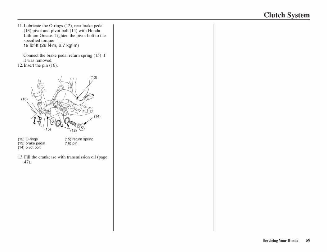
Clutch System11. Lubricate the O-rings (12), rear brake pedal
(13) pivot and pivot bolt (14) with HondaLithium Grease. Tighten the pivot bolt to thespecified torque:19 lbf·ft (26 N·m, 2.7 kgf·m)
Connect the brake pedal return spring (15) ifit was removed.
12. Insert the pin (16).
(12) O-rings (15) return spring(13) brake pedal (16) pin(14) pivot bolt
13.Fill the crankcase with transmission oil (page47).
Servicing Your Honda 59
(16)
(13)
(14)
(15) (12)
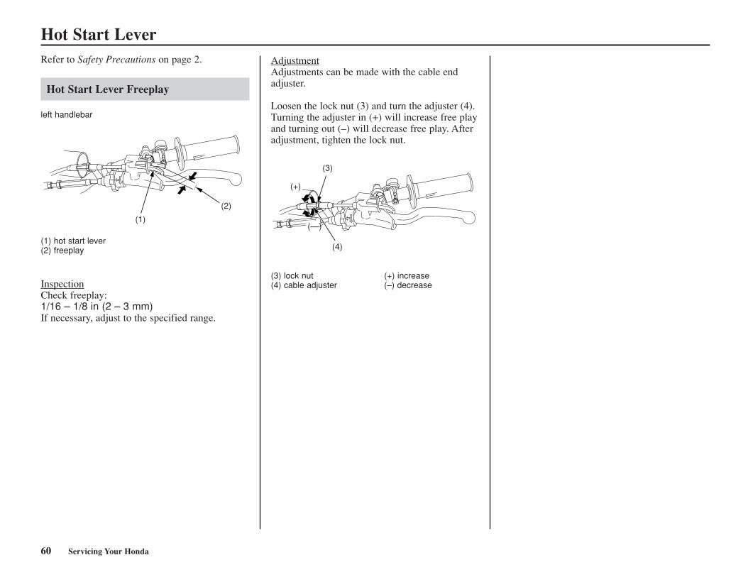
Hot Start LeverRefer to Safety Precautions on page 2.
Hot Start Lever Freeplay
left handlebar
(1) hot start lever(2) freeplay
InspectionCheck freeplay:1/16 – 1/8 in (2 – 3 mm)If necessary, adjust to the specified range.
AdjustmentAdjustments can be made with the cable endadjuster.
Loosen the lock nut (3) and turn the adjuster (4).Turning the adjuster in (+) will increase free playand turning out (–) will decrease free play. Afteradjustment, tighten the lock nut.
(3) lock nut (+) increase(4) cable adjuster (–) decrease
60 Servicing Your Honda
(1)
(2)
(+)
(—)
(4)
(3)
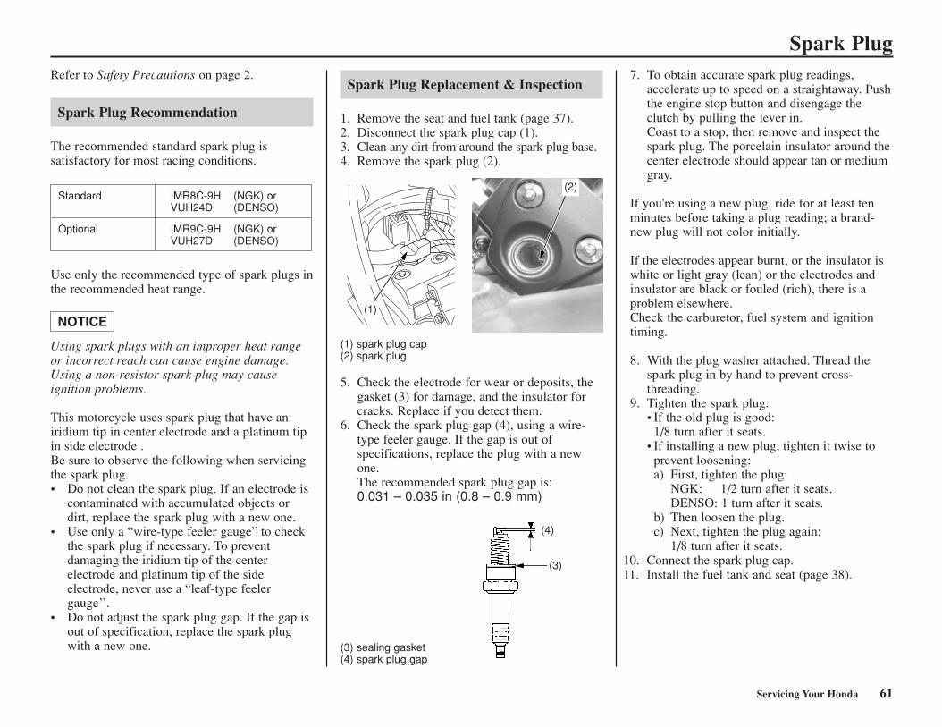
Refer to Safety Precautions on page 2.
Spark Plug Recommendation
The recommended standard spark plug is satisfactory for most racing conditions.
Use only the recommended type of spark plugs inthe recommended heat range.
Using spark plugs with an improper heat rangeor incorrect reach can cause engine damage.Using a non-resistor spark plug may cause ignition problems.
This motorcycle uses spark plug that have aniridium tip in center electrode and a platinum tipin side electrode .Be sure to observe the following when servicingthe spark plug.• Do not clean the spark plug. If an electrode is
contaminated with accumulated objects ordirt, replace the spark plug with a new one.
• Use only a “wire-type feeler gauge” to checkthe spark plug if necessary. To preventdamaging the iridium tip of the centerelectrode and platinum tip of the sideelectrode, never use a “leaf-type feelergauge’’.
• Do not adjust the spark plug gap. If the gap isout of specification, replace the spark plugwith a new one.
NOTICE
Spark Plug
Spark Plug Replacement & Inspection
1. Remove the seat and fuel tank (page 37).2. Disconnect the spark plug cap (1).3. Clean any dirt from around the spark plug base.4. Remove the spark plug (2).
(1) spark plug cap(2) spark plug
5. Check the electrode for wear or deposits, thegasket (3) for damage, and the insulator forcracks. Replace if you detect them.
6. Check the spark plug gap (4), using a wire-type feeler gauge. If the gap is out ofspecifications, replace the plug with a newone.The recommended spark plug gap is:0.031 – 0.035 in (0.8 – 0.9 mm)
(3) sealing gasket(4) spark plug gap
(3)
(4)
Servicing Your Honda 61
Standard IMR8C-9H (NGK) orVUH24D (DENSO)
Optional IMR9C-9H (NGK) orVUH27D (DENSO)
7. To obtain accurate spark plug readings,accelerate up to speed on a straightaway. Pushthe engine stop button and disengage theclutch by pulling the lever in. Coast to a stop, then remove and inspect thespark plug. The porcelain insulator around thecenter electrode should appear tan or mediumgray.
If you're using a new plug, ride for at least tenminutes before taking a plug reading; a brand-new plug will not color initially.
If the electrodes appear burnt, or the insulator iswhite or light gray (lean) or the electrodes andinsulator are black or fouled (rich), there is aproblem elsewhere.Check the carburetor, fuel system and ignitiontiming.
8. With the plug washer attached. Thread thespark plug in by hand to prevent cross-threading.
9. Tighten the spark plug:• If the old plug is good:
1/8 turn after it seats.• If installing a new plug, tighten it twise to
prevent loosening:a) First, tighten the plug:
NGK: 1/2 turn after it seats.DENSO: 1 turn after it seats.
b) Then loosen the plug.c) Next, tighten the plug again:
1/8 turn after it seats.
(2)
(1)
10. Connect the spark plug cap.11. Install the fuel tank and seat (page 38).
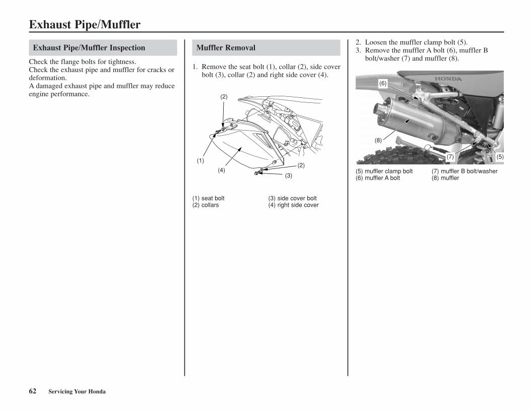
Exhaust Pipe/Muffler
Exhaust Pipe/Muffler Inspection
Check the flange bolts for tightness.Check the exhaust pipe and muffler for cracks ordeformation.A damaged exhaust pipe and muffler may reduceengine performance.
(1) seat bolt (3) side cover bolt(2) collars (4) right side cover
2. Loosen the muffler clamp bolt (5).3. Remove the muffler A bolt (6), muffler B
bolt/washer (7) and muffler (8).
(5) muffler clamp bolt (7) muffler B bolt/washer(6) muffler A bolt (8) muffler
(1)
(4)(3)
(2)
(2)
(6)
(8)
(7) (5)
Muffler Removal
1. Remove the seat bolt (1), collar (2), side coverbolt (3), collar (2) and right side cover (4).
62 Servicing Your Honda
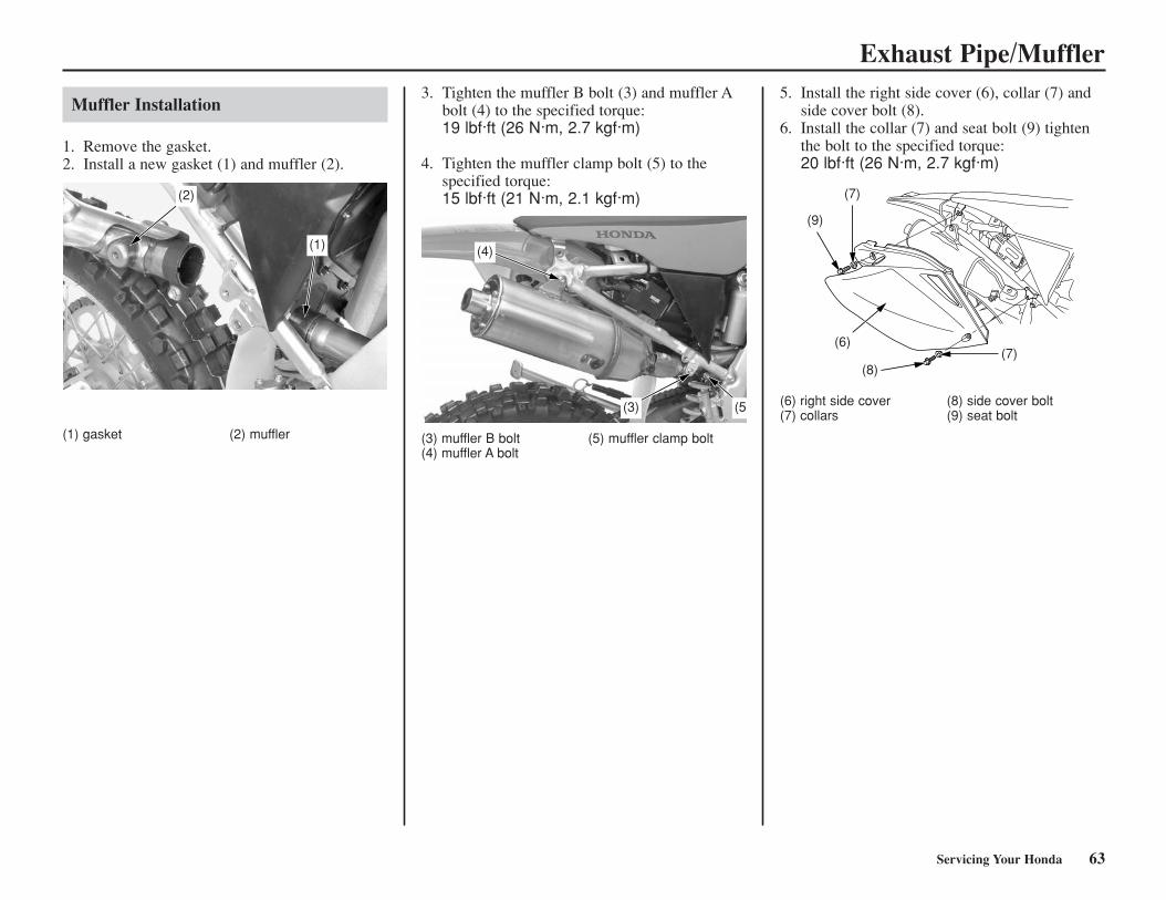
Exhaust Pipe/Muffler
Muffler Installation
1. Remove the gasket.2. Install a new gasket (1) and muffler (2).
(1) gasket (2) muffler
3. Tighten the muffler B bolt (3) and muffler Abolt (4) to the specified torque:19 lbf·ft (26 N·m, 2.7 kgf·m)
4. Tighten the muffler clamp bolt (5) to thespecified torque:15 lbf·ft (21 N·m, 2.1 kgf·m)
(3) muffler B bolt (5) muffler clamp bolt(4) muffler A bolt
(6) right side cover (8) side cover bolt(7) collars (9) seat bolt
5. Install the right side cover (6), collar (7) andside cover bolt (8).
6. Install the collar (7) and seat bolt (9) tightenthe bolt to the specified torque:20 lbf·ft (26 N·m, 2.7 kgf·m)
Servicing Your Honda 63
(2)
(1) (4)
(5(3)
(9)
(6)
(8)(7)
(7)
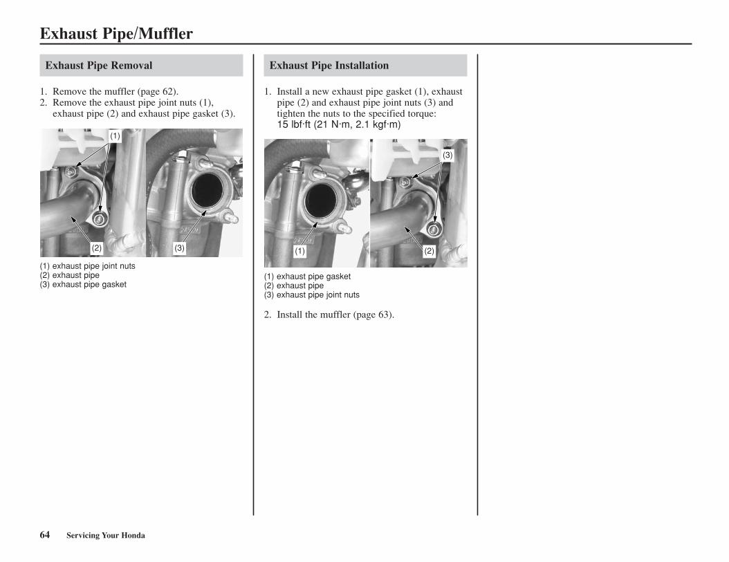
Exhaust Pipe/Muffler
64 Servicing Your Honda
Exhaust Pipe Installation
1. Install a new exhaust pipe gasket (1), exhaustpipe (2) and exhaust pipe joint nuts (3) andtighten the nuts to the specified torque:15 lbf·ft (21 N·m, 2.1 kgf·m)
(1) exhaust pipe gasket(2) exhaust pipe(3) exhaust pipe joint nuts
2. Install the muffler (page 63).
Exhaust Pipe Removal
1. Remove the muffler (page 62).2. Remove the exhaust pipe joint nuts (1),
exhaust pipe (2) and exhaust pipe gasket (3).
(1) exhaust pipe joint nuts(2) exhaust pipe(3) exhaust pipe gasket
(1)
(2) (3) (1) (2)
(3)
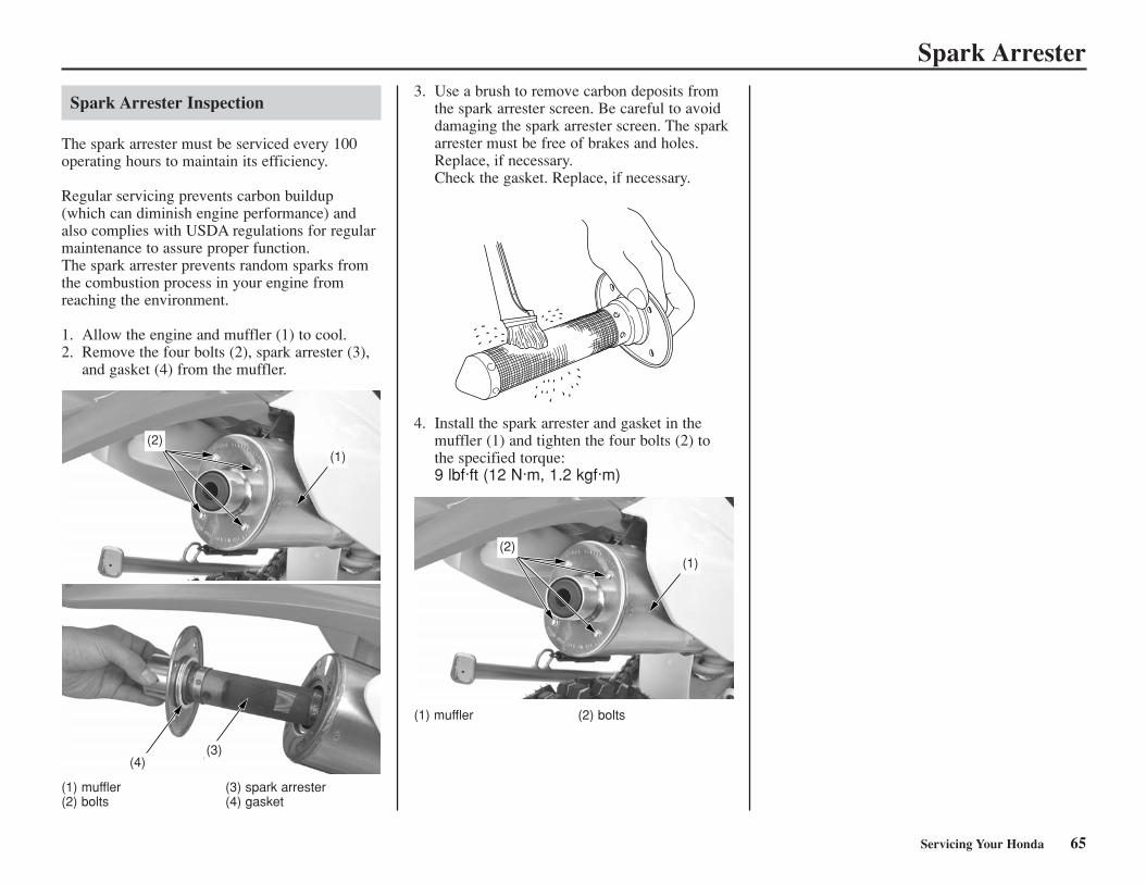
Spark Arrester
Servicing Your Honda 65
Spark Arrester Inspection
The spark arrester must be serviced every 100operating hours to maintain its efficiency.
Regular servicing prevents carbon buildup(which can diminish engine performance) andalso complies with USDA regulations for regularmaintenance to assure proper function.The spark arrester prevents random sparks fromthe combustion process in your engine fromreaching the environment.
1. Allow the engine and muffler (1) to cool.2. Remove the four bolts (2), spark arrester (3),
and gasket (4) from the muffler.
(1) muffler (3) spark arrester(2) bolts (4) gasket
3. Use a brush to remove carbon deposits fromthe spark arrester screen. Be careful to avoiddamaging the spark arrester screen. The sparkarrester must be free of brakes and holes.Replace, if necessary.Check the gasket. Replace, if necessary.
4. Install the spark arrester and gasket in themuffler (1) and tighten the four bolts (2) tothe specified torque:9 lbf·ft (12 N·m, 1.2 kgf·m)
(1) muffler (2) bolts
(2)(1)
(4)(3)
(2)(1)
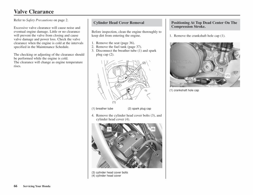
Valve Clearance
Cylinder Head Cover Removal
Before inspection, clean the engine thoroughly tokeep dirt from entering the engine.
1. Remove the seat (page 36).2. Remove the fuel tank (page 37).3. Disconnect the breather tube (1) and spark
plug cap (2).
Positioning At Top Dead Center On TheCompression Stroke.
1. Remove the crankshaft hole cap (1).
(1) breather tube (2) spark plug cap
4. Remove the cylinder head cover bolts (3), andcylinder head cover (4).
(3) cylinder head cover bolts(4) cylinder head cover
(1) crankshaft hole cap
(1)
(2)
(3) (4)
(1)
Refer to Safety Precautions on page 2.
Excessive valve clearance will cause noise andeventual engine damage. Little or no clearancewill prevent the valve from closing and causevalve damage and power loss. Check the valveclearance when the engine is cold at the intervalsspecified in the Maintenance Schedule.
The checking or adjusting of the clearance shouldbe performed while the engine is cold.The clearance will change as engine temperaturerises.
66 Servicing Your Honda
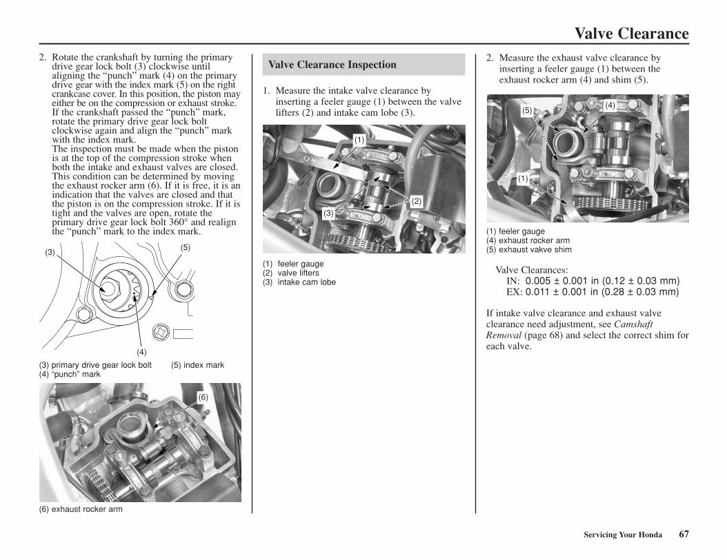
Valve Clearance
Valve Clearance Inspection
1. Measure the intake valve clearance byinserting a feeler gauge (1) between the valvelifters (2) and intake cam lobe (3).
2. Measure the exhaust valve clearance byinserting a feeler gauge (1) between theexhaust rocker arm (4) and shim (5).
(1) feeler gauge(4) exhaust rocker arm(5) exhaust vakve shim
Valve Clearances:IN: 0.005 ± 0.001 in (0.12 ± 0.03 mm)EX: 0.011 ± 0.001 in (0.28 ± 0.03 mm)
If intake valve clearance and exhaust valveclearance need adjustment, see CamshaftRemoval (page 68) and select the correct shim foreach valve.
(6)
(1)
(3)(2)
(5)
(1)
(4)
(1) feeler gauge(2) valve lifters(3) intake cam lobe
2. Rotate the crankshaft by turning the primarydrive gear lock bolt (3) clockwise untilaligning the “punch” mark (4) on the primarydrive gear with the index mark (5) on the rightcrankcase cover. In this position, the piston mayeither be on the compression or exhaust stroke.If the crankshaft passed the “punch” mark,rotate the primary drive gear lock boltclockwise again and align the “punch” markwith the index mark.The inspection must be made when the pistonis at the top of the compression stroke whenboth the intake and exhaust valves are closed.This condition can be determined by movingthe exhaust rocker arm (6). If it is free, it is anindication that the valves are closed and thatthe piston is on the compression stroke. If it istight and the valves are open, rotate theprimary drive gear lock bolt 360° and realignthe “punch” mark to the index mark.
(3)
(4)
(5)
(3) primary drive gear lock bolt (5) index mark(4) “punch” mark
(6) exhaust rocker arm
Servicing Your Honda 67
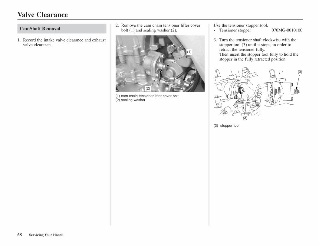
Valve Clearance
CamShaft Removal
1. Record the intake valve clearance and exhaustvalve clearance.
2. Remove the cam chain tensioner lifter coverbolt (1) and sealing washer (2).
(1) cam chain tensioner lifter cover bolt(2) sealing washer
Use the tensioner stopper tool.• Tensioner stopper 070MG-0010100
3. Turn the tensioner shaft clockwise with thestopper tool (3) until it stops, in order toretract the tensioner fully.Then insert the stopper tool fully to hold thestopper in the fully retracted position.
(3) stopper tool
(1)
(2)
(3)
(3)
68 Servicing Your Honda
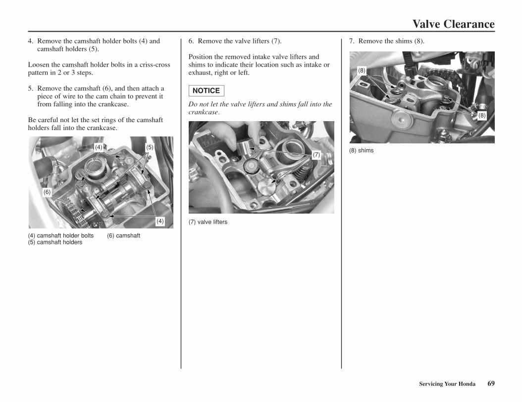
Valve Clearance4. Remove the camshaft holder bolts (4) and
camshaft holders (5).
Loosen the camshaft holder bolts in a criss-crosspattern in 2 or 3 steps.
5. Remove the camshaft (6), and then attach apiece of wire to the cam chain to prevent itfrom falling into the crankcase.
Be careful not let the set rings of the camshaftholders fall into the crankcase.
(4) camshaft holder bolts (6) camshaft(5) camshaft holders
6. Remove the valve lifters (7).
Position the removed intake valve lifters andshims to indicate their location such as intake orexhaust, right or left.
Do not let the valve lifters and shims fall into thecrankcase.
NOTICE
(7) valve lifters
7. Remove the shims (8).
(4)
(4)
(5)
(6)
(7)
(8)
(8)
Servicing Your Honda 69
(8) shims
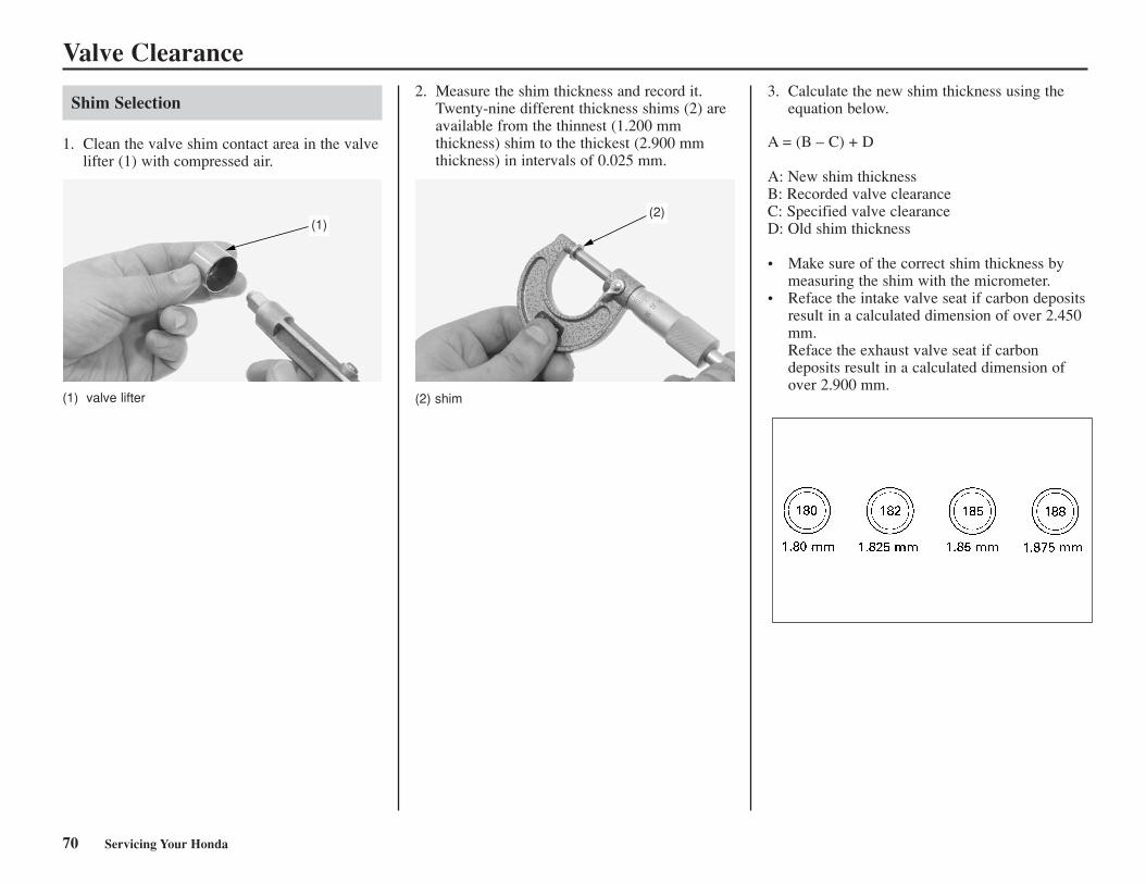
Valve Clearance
Shim Selection
1. Clean the valve shim contact area in the valvelifter (1) with compressed air.
2. Measure the shim thickness and record it.Twenty-nine different thickness shims (2) areavailable from the thinnest (1.200 mmthickness) shim to the thickest (2.900 mmthickness) in intervals of 0.025 mm.
3. Calculate the new shim thickness using theequation below.
A = (B – C) + D
A: New shim thicknessB: Recorded valve clearanceC: Specified valve clearanceD: Old shim thickness
• Make sure of the correct shim thickness bymeasuring the shim with the micrometer.
• Reface the intake valve seat if carbon depositsresult in a calculated dimension of over 2.450mm.Reface the exhaust valve seat if carbondeposits result in a calculated dimension ofover 2.900 mm.
(1)(2)
(2) shim
70 Servicing Your Honda
(1) valve lifter
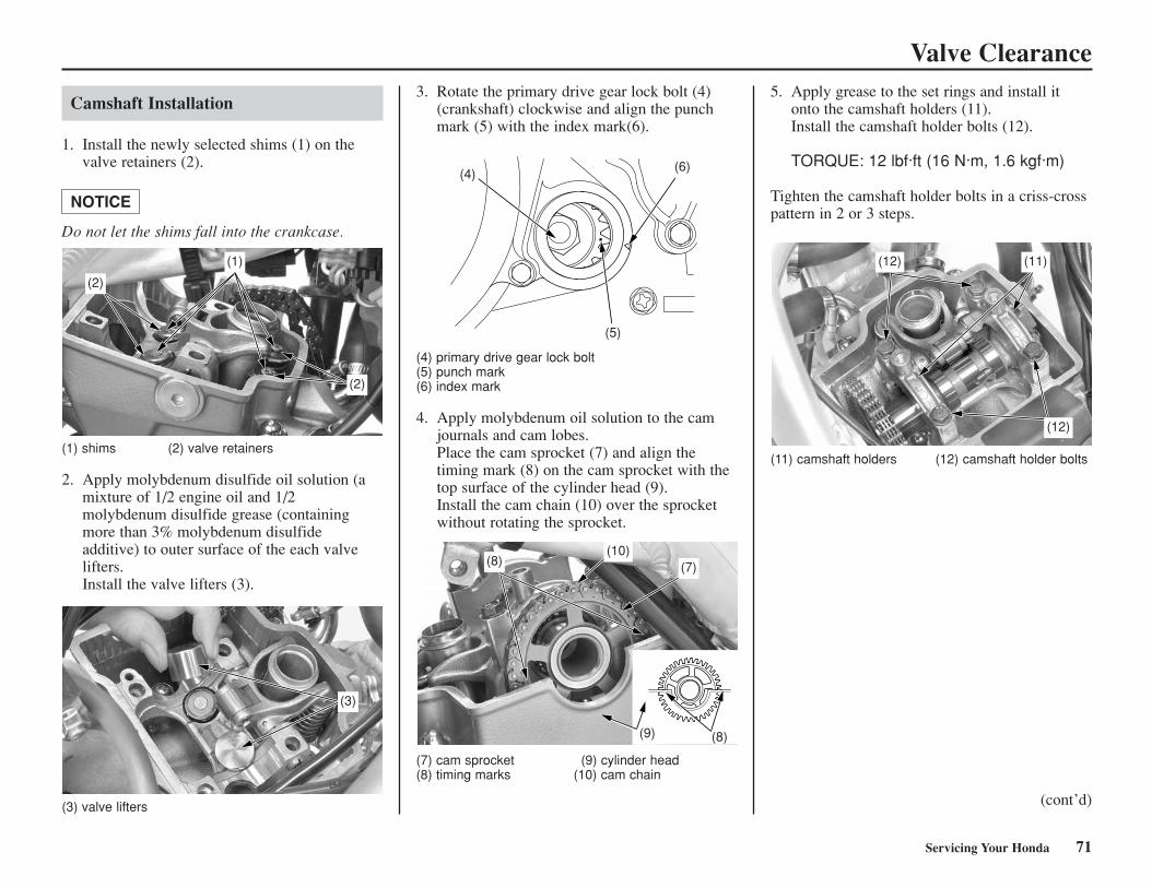
Valve Clearance
Camshaft Installation
1. Install the newly selected shims (1) on thevalve retainers (2).
Do not let the shims fall into the crankcase.
NOTICE
(1) shims (2) valve retainers
2. Apply molybdenum disulfide oil solution (amixture of 1/2 engine oil and 1/2molybdenum disulfide grease (containingmore than 3% molybdenum disulfideadditive) to outer surface of the each valvelifters.Install the valve lifters (3).
3. Rotate the primary drive gear lock bolt (4)(crankshaft) clockwise and align the punchmark (5) with the index mark(6).
(7) cam sprocket (9) cylinder head(8) timing marks (10) cam chain
5. Apply grease to the set rings and install itonto the camshaft holders (11).Install the camshaft holder bolts (12).
TORQUE: 12 lbf·ft (16 N·m, 1.6 kgf·m)
Tighten the camshaft holder bolts in a criss-crosspattern in 2 or 3 steps.
(11) camshaft holders (12) camshaft holder bolts
(2)
(2)
(1)
(4)
(5)
(6)
(12)
(12)
(11)
Servicing Your Honda 71
(3) valve lifters
(4) primary drive gear lock bolt(5) punch mark(6) index mark
4. Apply molybdenum oil solution to the camjournals and cam lobes.Place the cam sprocket (7) and align thetiming mark (8) on the cam sprocket with thetop surface of the cylinder head (9).Install the cam chain (10) over the sprocketwithout rotating the sprocket.
(cont’d)
(3)
(8)
(9) (8)
(10)(7)
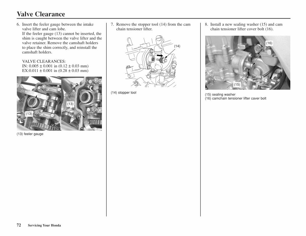
Valve Clearance
72 Servicing Your Honda
6. Insert the feeler gauge between the intakevalve lifter and cam lobe.If the feeler gauge (13) cannot be inserted, theshim is caught between the valve lifter and thevalve retainer. Remove the camshaft holdersto place the shim correctly, and reinstall thecamshaft holders.
VALVE CLEARANCES:IN: 0.005 ± 0.001 in (0.12 ± 0.03 mm)EX:0.011 ± 0.001 in (0.28 ± 0.03 mm)
(13) feeler gauge
7. Remove the stopper tool (14) from the camchain tensioner lifter.
(14) stopper tool
8. Install a new sealing washer (15) and camchain tensioner lifter cover bolt (16).
(15) sealing washer(16) camchain tensioner lifter caver bolt
(13)
(13)
(14)
(15)
(16)
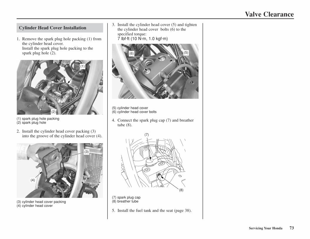
Valve Clearance
Cylinder Head Cover Installation
1. Remove the spark plug hole packing (1) fromthe cylinder head cover.Install the spark plug hole packing to thespark plug hole (2).
(1) spark plug hole packing(2) spark plug hole
2. Install the cylinder head cover packing (3)into the groove of the cylinder head cover (4).
(3) cylinder head cover packing(4) cylinder head cover
3. Install the cylinder head cover (5) and tightenthe cylinder head cover bolts (6) to thespecified torque:7 lbf·ft (10 N·m, 1.0 kgf·m)
(5) cylinder head cover(6) cylinder head cover bolts
4. Connect the spark plug cap (7) and breathertube (8).
(7) spark plug cap(8) breather tube
5. Install the fuel tank and the seat (page 38).
(2)
(1)
(3)
(4)
Servicing Your Honda 73
(6) (5)
(7)
(8)
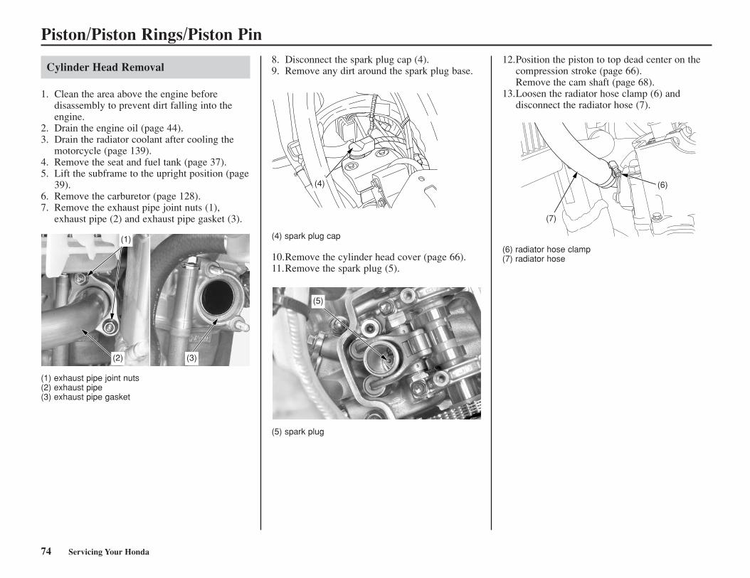
Piston/Piston Rings/Piston Pin
Cylinder Head Removal
1. Clean the area above the engine beforedisassembly to prevent dirt falling into theengine.
2. Drain the engine oil (page 44).3. Drain the radiator coolant after cooling the
motorcycle (page 139).4. Remove the seat and fuel tank (page 37).5. Lift the subframe to the upright position (page
39).6. Remove the carburetor (page 128).7. Remove the exhaust pipe joint nuts (1),
exhaust pipe (2) and exhaust pipe gasket (3).
(1) exhaust pipe joint nuts(2) exhaust pipe(3) exhaust pipe gasket
8. Disconnect the spark plug cap (4).9. Remove any dirt around the spark plug base.
(4) spark plug cap
10.Remove the cylinder head cover (page 66).11.Remove the spark plug (5).
(5) spark plug
12.Position the piston to top dead center on thecompression stroke (page 66).Remove the cam shaft (page 68).
13.Loosen the radiator hose clamp (6) anddisconnect the radiator hose (7).
(6) radiator hose clamp(7) radiator hose
(1)
(2) (3)
(4)
(5)
(7)
(6)
74 Servicing Your Honda
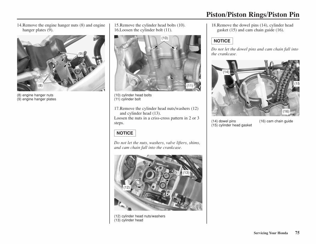
Piston/Piston Rings/Piston Pin14.Remove the engine hanger nuts (8) and engine
hanger plates (9).
(8) engine hanger nuts(9) engine hanger plates
15.Remove the cylinder head bolts (10).16.Loosen the cylinder bolt (11).
(10) cylinder head bolts(11) cylinder bolt
17.Remove the cylinder head nuts/washers (12)and cylinder head (13).
Loosen the nuts in a criss-cross pattern in 2 or 3steps.
Do not let the nuts, washers, valve lifters, shims,and cam chain fall into the crankcase.
NOTICE
(12) cylinder head nuts/washers(13) cylinder head
18.Remove the dowel pins (14), cylinder headgasket (15) and cam chain guide (16).
Do not let the dowel pins and cam chain fall intothe crankcase.
NOTICE
(14) dowel pins (16) cam chain guide(15) cylinder head gasket
(9)
(8)
(10)
(11)
(14)
(16)
(15
Servicing Your Honda 75
(13)
(12)
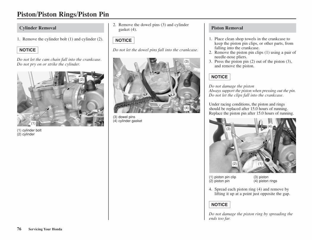
Piston/Piston Rings/Piston Pin
Cylinder Removal
1. Remove the cylinder bolt (1) and cylinder (2).
Do not let the cam chain fall into the crankcase.Do not pry on or strike the cylinder.
NOTICE
(1) cylinder bolt(2) cylinder
2. Remove the dowel pins (3) and cylindergasket (4).
Do not let the dowel pins fall into the crankcase.
NOTICE
(3) dowel pins(4) cylinder gasket
Piston Removal
1. Place clean shop towels in the crankcase tokeep the piston pin clips, or other parts, fromfalling into the crankcase.
2. Remove the piston pin clips (1) using a pair ofneedle-nose pliers.
3. Press the piston pin (2) out of the piston (3),and remove the piston.
Do not damage the pistonAlways support the piston when pressing out the pin.Do not let the clips fall into the crankcase.
Under racing conditions, the piston and ringsshould be replaced after 15.0 hours of running.Replace the piston pin after 15.0 hours of running.
NOTICE
(1) piston pin clip (3) piston(2) piston pin (4) piston rings
4. Spread each piston ring (4) and remove bylifting it up at a point just opposite the gap.
Do not damage the piston ring by spreading theends too far.
NOTICE
(1)
(2)
(3)
(4)
(3)(4)
(2) (1)
76 Servicing Your Honda
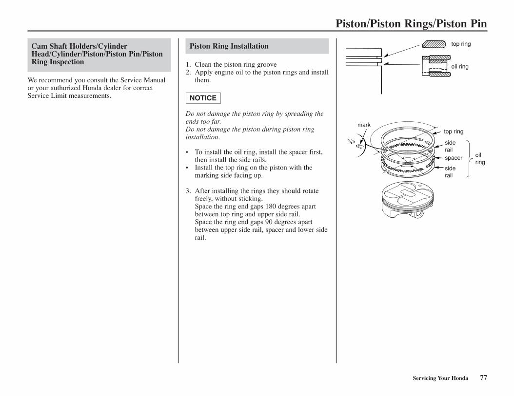
Piston/Piston Rings/Piston Pin
Piston Ring Installation
1. Clean the piston ring groove 2. Apply engine oil to the piston rings and install
them.
Do not damage the piston ring by spreading theends too far.Do not damage the piston during piston ringinstallation.
• To install the oil ring, install the spacer first,then install the side rails.
• Install the top ring on the piston with themarking side facing up.
3. After installing the rings they should rotatefreely, without sticking.Space the ring end gaps 180 degrees apartbetween top ring and upper side rail.Space the ring end gaps 90 degrees apartbetween upper side rail, spacer and lower siderail.
NOTICE
top ring
oil ring
top ringmark
siderail
oilring
siderail
spacer
Servicing Your Honda 77
Cam Shaft Holders/CylinderHead/Cylinder/Piston/Piston Pin/PistonRing Inspection
We recommend you consult the Service Manualor your authorized Honda dealer for correctService Limit measurements.
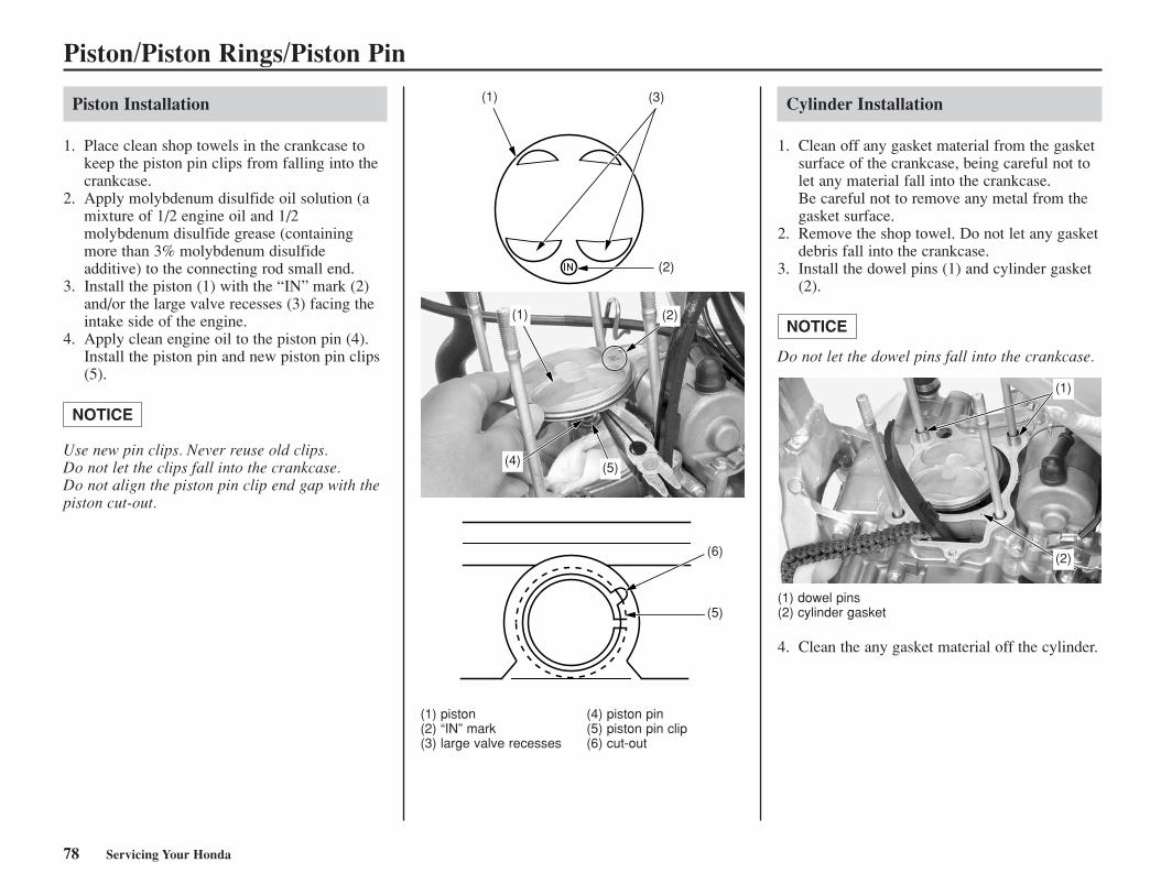
Piston/Piston Rings/Piston Pin
Piston Installation
1. Place clean shop towels in the crankcase tokeep the piston pin clips from falling into thecrankcase.
2. Apply molybdenum disulfide oil solution (amixture of 1/2 engine oil and 1/2molybdenum disulfide grease (containingmore than 3% molybdenum disulfideadditive) to the connecting rod small end.
3. Install the piston (1) with the “IN” mark (2)and/or the large valve recesses (3) facing theintake side of the engine.
4. Apply clean engine oil to the piston pin (4).Install the piston pin and new piston pin clips(5).
Use new pin clips. Never reuse old clips.Do not let the clips fall into the crankcase.Do not align the piston pin clip end gap with thepiston cut-out.
NOTICE
(1) piston (4) piston pin(2) “IN” mark (5) piston pin clip(3) large valve recesses (6) cut-out
Cylinder Installation
1. Clean off any gasket material from the gasketsurface of the crankcase, being careful not tolet any material fall into the crankcase.Be careful not to remove any metal from thegasket surface.
2. Remove the shop towel. Do not let any gasketdebris fall into the crankcase.
3. Install the dowel pins (1) and cylinder gasket(2).
Do not let the dowel pins fall into the crankcase.
NOTICE
(1) dowel pins(2) cylinder gasket
4. Clean the any gasket material off the cylinder.
(1) (3)
(2)
(1)
(4) (5)
(2)
(6)
(5)
(2)
(1)
78 Servicing Your Honda
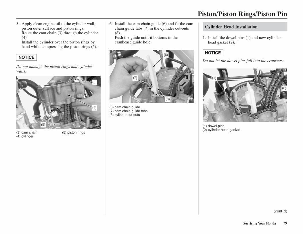
Piston/Piston Rings/Piston Pin5. Apply clean engine oil to the cylinder wall,
piston outer surface and piston rings.Route the cam chain (3) through the cylinder(4).Install the cylinder over the piston rings byhand while compressing the piston rings (5).
Do not damage the piston rings and cylinderwalls.
NOTICE
(3) cam chain (5) piston rings(4) cylinder
6. Install the cam chain guide (6) and fit the camchain guide tabs (7) in the cylinder cut-outs(8).Push the guide until it bottoms in thecrankcase guide hole.
(6) cam chain guide(7) cam chain guide tabs(8) cylinder cut-outs
Cylinder Head Installation
1. Install the dowel pins (1) and new cylinderhead gasket (2).
Do not let the dowel pins fall into the crankcase.
NOTICE
(1) dowel pins(2) cylinder head gasket
(3)
(4)
(5)
(6)
(7)
(8)
(1)
(2)
Servicing Your Honda 79
(cont’d)
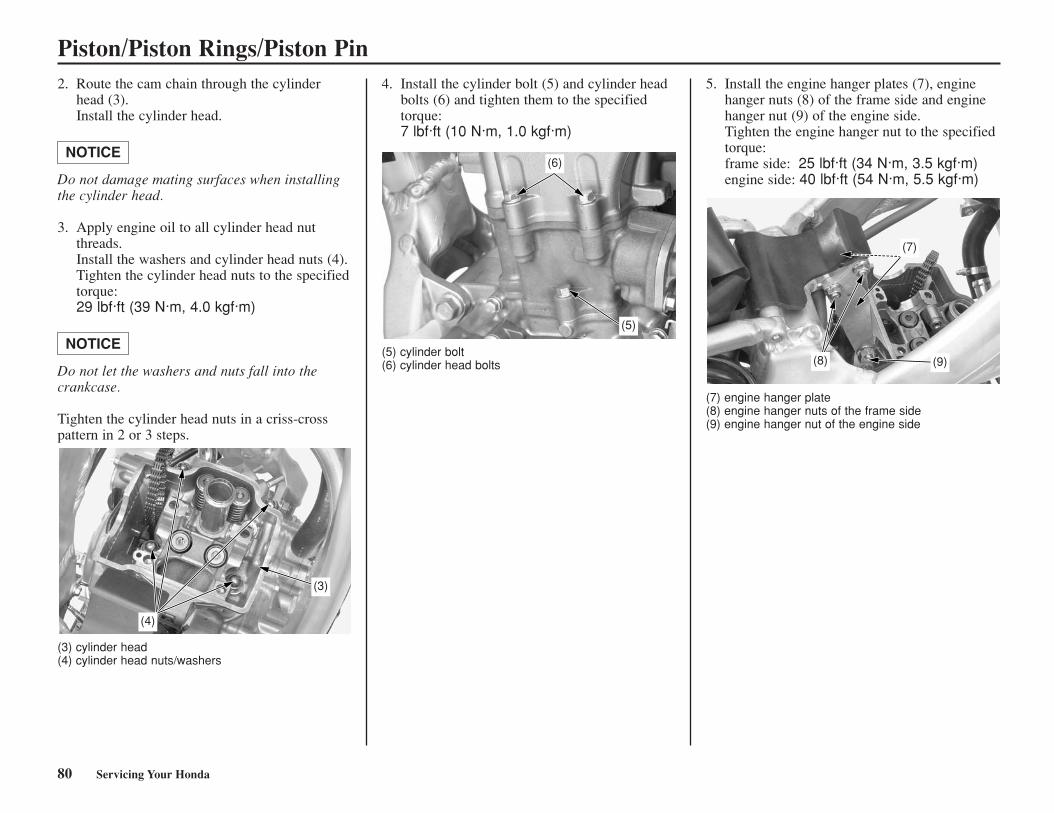
Piston/Piston Rings/Piston Pin2. Route the cam chain through the cylinder
head (3).Install the cylinder head.
Do not damage mating surfaces when installingthe cylinder head.
3. Apply engine oil to all cylinder head nutthreads.Install the washers and cylinder head nuts (4).Tighten the cylinder head nuts to the specifiedtorque:29 lbf·ft (39 N·m, 4.0 kgf·m)
Do not let the washers and nuts fall into thecrankcase.
Tighten the cylinder head nuts in a criss-crosspattern in 2 or 3 steps.
NOTICE
NOTICE
4. Install the cylinder bolt (5) and cylinder headbolts (6) and tighten them to the specifiedtorque:7 lbf·ft (10 N·m, 1.0 kgf·m)
(3) cylinder head(4) cylinder head nuts/washers
(5) cylinder bolt(6) cylinder head bolts
(7) engine hanger plate(8) engine hanger nuts of the frame side(9) engine hanger nut of the engine side
(4)
(3)
(6)
(5)
(7)
(8) (9)
80 Servicing Your Honda
5. Install the engine hanger plates (7), enginehanger nuts (8) of the frame side and enginehanger nut (9) of the engine side.Tighten the engine hanger nut to the specifiedtorque:frame side: 25 lbf·ft (34 N·m, 3.5 kgf·m)engine side: 40 lbf·ft (54 N·m, 5.5 kgf·m)
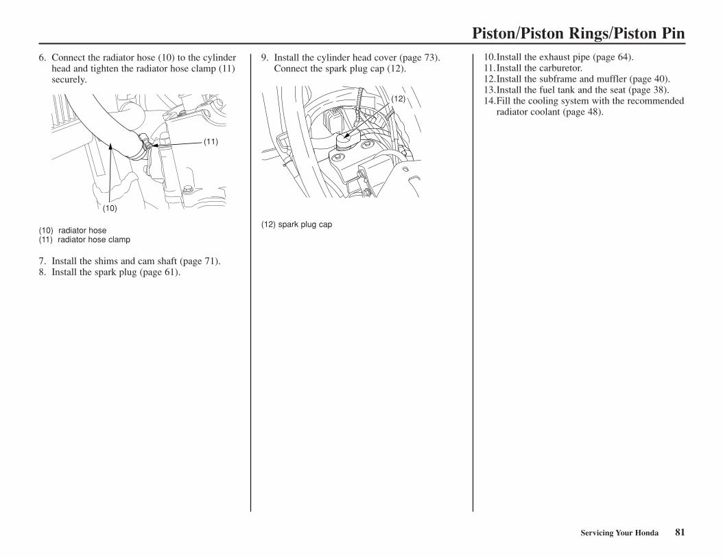
Piston/Piston Rings/Piston Pin6. Connect the radiator hose (10) to the cylinder
head and tighten the radiator hose clamp (11)securely.
(10) radiator hose(11) radiator hose clamp
7. Install the shims and cam shaft (page 71).8. Install the spark plug (page 61).
9. Install the cylinder head cover (page 73).Connect the spark plug cap (12).
(12) spark plug cap
10.Install the exhaust pipe (page 64).11.Install the carburetor.12.Install the subframe and muffler (page 40).13.Install the fuel tank and the seat (page 38).14.Fill the cooling system with the recommended
radiator coolant (page 48).
(10)
(11)
Servicing Your Honda 81
(12)
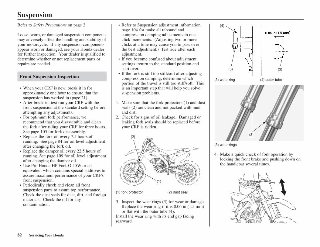
SuspensionRefer to Safety Precautions on page 2
Loose, worn, or damaged suspension componentsmay adversely affect the handling and stability ofyour motorcycle. If any suspension componentsappear worn or damaged, see your Honda dealerfor further inspection. Your dealer is qualified todetermine whether or not replacement parts orrepairs are needed.
Front Suspension Inspection
• When your CRF is new, break it in forapproximately one hour to ensure that thesuspension has worked in (page 21).
• After break-in, test run your CRF with thefront suspension at the standard setting beforeattempting any adjustments.
• For optimum fork performance, werecommend that you disassemble and cleanthe fork after riding your CRF for three hours.See page 105 for fork disassembly.
• Replace the fork oil every 7.5 hours ofrunning. See page 84 for oil level adjustmentafter changing the fork oil.
• Replace the damper oil every 22.5 hours ofrunning. See page 109 for oil level adjustmentafter changing the damper oil.
• Use Pro Honda HP Fork Oil 5W or anequivalent which contains special additives toassure maximum performance of your CRF'sfront suspension.
• Periodically check and clean all frontsuspension parts to assure top performance.Check the dust seals for dust, dirt, and foreignmaterials. Check the oil for anycontamination.
• Refer to Suspension adjustment informationpage 104 for make all rebound andcompression damping adjustments in one-click increments. (Adjusting two or moreclicks at a time may cause you to pass overthe best adjustment.) Test ride after eachadjustment.
• If you become confused about adjustmentsettings, return to the standard position andstart over.
• If the fork is still too stiff/soft after adjustingcompression damping, determine whichportion of the travel is still too stiff/soft. Thisis an important step that will help you solvesuspension problems.
1. Make sure that the fork protectors (1) and dustseals (2) are clean and not packed with mudand dirt.
2. Check for signs of oil leakage. Damaged orleaking fork seals should be replaced beforeyour CRF is ridden.
(1) fork protector (2) dust seal
3. Inspect the wear rings (3) for wear or damage.Replace the wear ring if it is 0.06 in (1.5 mm)or flat with the outer tube (4).
Install the wear ring with its end gap facingrearward.
(3) wear ring (4) outer tube
(3) wear rings
4. Make a quick check of fork operation bylocking the front brake and pushing down onthe handlebar several times.
(1)
(2)
(3)
(4)
(3)
(3)
82 Servicing Your Honda
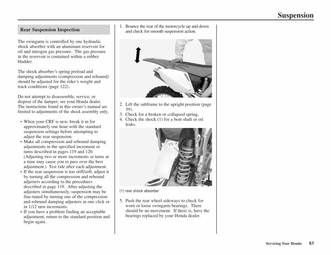
Suspension
Rear Suspension Inspection
The swingarm is controlled by one hydraulicshock absorber with an aluminum reservoir foroil and nitrogen gas pressure. The gas pressurein the reservoir is contained within a rubberbladder.
The shock absorber’s spring preload anddamping adjustments (compression and rebound)should be adjusted for the rider’s weight andtrack conditions (page 122).
Do not attempt to disassemble, service, ordispose of the damper; see your Honda dealer.The instructions found in this owner’s manual arelimited to adjustments of the shock assembly only.
• When your CRF is new, break it in forapproximately one hour with the standardsuspension settings before attempting toadjust the rear suspension.
• Make all compression and rebound dampingadjustments in the specified increment orturns described in pages 119 and 120.(Adjusting two or more increments or turns ata time may cause you to pass over the bestadjustment.) Test ride after each adjustment.
• If the rear suspension is too stiff/soft, adjust itby turning all the compression and reboundadjusters according to the proceduresdescribed in page 119. After adjusting theadjusters simultaneously, suspension may befine-tuned by turning one of the compressionand rebound damping adjusters in one click orin 1/12 turn increments.
• If you have a problem finding an acceptableadjustment, return to the standard position andbegin again.
1. Bounce the rear of the motorcycle up and downand check for smooth suspension action.
2. Lift the subframe to the upright position (page39).
3. Check for a broken or collapsed spring.4. Check the shock (1) for a bent shaft or oil
leaks.
(1) rear shock absorber
5. Push the rear wheel sideways to check forworn or loose swingarm bearings. Thereshould be no movement. If there is, have thebearings replaced by your Honda dealer.
(1)
Servicing Your Honda 83
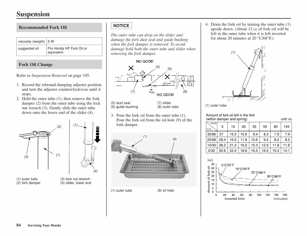
Suspension
84 Servicing Your Honda
Recommended Fork Oil
Fork Oil Change
Refer to Suspension Removal on page 105.
1. Record the rebound damping adjuster positionand turn the adjuster counterclockwise until itstops.
2. Hold the outer tube (1), then remove the forkdamper (2) from the outer tube using the locknut wrench (3). Gently slide the outer tubedown onto the lower end of the slider (4).
viscosity (weight) 5 W
suggested oil Pro Honda HP Fork Oil orequivalent
(1) outer tube (3) lock nut wrench(2) fork damper (4) slider, lower end
The outer tube can drop on the slider anddamage the fork dust seal and guide bushingwhen the fork damper is removed. To avoiddamage hold both the outer tube and slider whenremoving the fork damper.
NOTICE
(5) dust seal (7) slider(6) guide bushing (8) outer tube
3. Pour the fork oil from the outer tube (1).Pour the fork oil from the oil hole (9) of thefork damper.
(1) outer tube (9) oil hole
4. Drain the fork oil by turning the outer tube (1)upside down. (About 12 cc of fork oil will beleft in the outer tube when it is left invertedfor about 20 minutes at 20 °C/68°F.)
(1) outer tube
Amount of fork oil left in the fork(within damper and spring) unit: cc
minute
°C/°F
30/86
20/68
10/50
0/32
5
27
29.4
28.2
30.6
10
15.3
16.5
21.2
22.4
20
10.6
11.8
16.5
18.8
35
9.4
10.6
15.3
16.5
55
8.3
9.4
12.9
16.5
85
7.9
8.2
11.8
15.3
145
7.9
8.2
11.8
14.1
(3)
(2)
(1)
(1)
(4)
(5) (6)
(7) (8)
(1)(9)
(1)
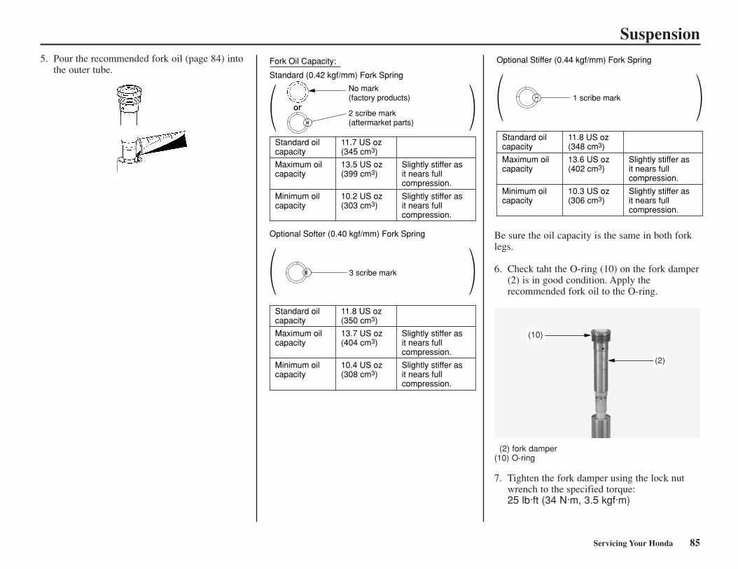
Servicing Your Honda 85
Suspension5. Pour the recommended fork oil (page 84) into
the outer tube.Fork Oil Capacity: Standard (0.42 kgf/mm) Fork Spring
or
Standard oilcapacity
11.7 US oz(345 cm3)
Maximum oilcapacity
13.5 US oz(399 cm3)
Slightly stiffer asit nears fullcompression.
Slightly stiffer asit nears fullcompression.
Minimum oilcapacity
10.2 US oz(303 cm3)
Optional Softer (0.40 kgf/mm) Fork Spring
Standard oilcapacity
11.8 US oz(350 cm3)
Maximum oilcapacity
13.7 US oz(404 cm3)
Slightly stiffer asit nears fullcompression.
Slightly stiffer asit nears fullcompression.
Minimum oilcapacity
10.4 US oz(308 cm3)
2 scribe mark(aftermarket parts)
No mark(factory products)
3 scribe mark
Optional Stiffer (0.44 kgf/mm) Fork Spring
Standard oilcapacity
11.8 US oz(348 cm3)
Maximum oilcapacity
13.6 US oz(402 cm3)
Slightly stiffer asit nears fullcompression.
Slightly stiffer asit nears fullcompression.
Minimum oilcapacity
10.3 US oz(306 cm3)
1 scribe mark
Be sure the oil capacity is the same in both forklegs.
6. Check taht the O-ring (10) on the fork damper(2) is in good condition. Apply therecommended fork oil to the O-ring.
(2) fork damper(10) O-ring
7. Tighten the fork damper using the lock nutwrench to the specified torque:25 lb·ft (34 N·m, 3.5 kgf·m)
(10)
(2)
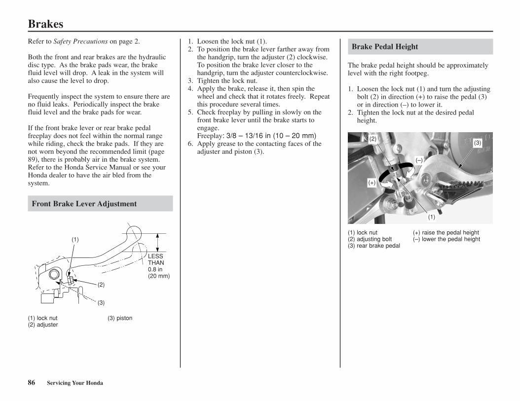
86 Servicing Your Honda
BrakesRefer to Safety Precautions on page 2.
Both the front and rear brakes are the hydraulicdisc type. As the brake pads wear, the brakefluid level will drop. A leak in the system willalso cause the level to drop.
Frequently inspect the system to ensure there areno fluid leaks. Periodically inspect the brakefluid level and the brake pads for wear.
If the front brake lever or rear brake pedalfreeplay does not feel within the normal rangewhile riding, check the brake pads. If they arenot worn beyond the recommended limit (page89), there is probably air in the brake system.Refer to the Honda Service Manual or see yourHonda dealer to have the air bled from thesystem.
Front Brake Lever Adjustment
(1) lock nut (3) piston(2) adjuster
1. Loosen the lock nut (1).2. To position the brake lever farther away from
the handgrip, turn the adjuster (2) clockwise.To position the brake lever closer to thehandgrip, turn the adjuster counterclockwise.
3. Tighten the lock nut.4. Apply the brake, release it, then spin the
wheel and check that it rotates freely. Repeatthis procedure several times.
5. Check freeplay by pulling in slowly on thefront brake lever until the brake starts toengage.Freeplay: 3/8 – 13/16 in (10 – 20 mm)
6. Apply grease to the contacting faces of theadjuster and piston (3).
Brake Pedal Height
The brake pedal height should be approximatelylevel with the right footpeg.
1. Loosen the lock nut (1) and turn the adjustingbolt (2) in direction (+) to raise the pedal (3)or in direction (–) to lower it.
2. Tighten the lock nut at the desired pedalheight.
(1) lock nut (+) raise the pedal height(2) adjusting bolt (–) lower the pedal height(3) rear brake pedal
LESSTHAN0.8 in(20 mm)
(1)
(2)
(3)
(2)
(1)
(3)
(+)
(–)

Servicing Your Honda 87
Brakes
Fluid Level Inspection
Front Brake Fluid Level Check
(1) LOWER level mark
With the motorcycle in an upright position, checkthe fluid level.It should be above the LOWER level mark (1). Ifthe level is at or below the LOWER level mark,check the brake pads for wear (page 89).Worn brake pads should be replaced. If the padsare not worn, have your brake system inspectedfor leaks.If the brake level freeplay exceeds 0.8 in (20 mm), there is probably air in the brake system and it must be bled. Refer to the HondaService Manual or see your Honda motorcycledealer for brake bleeding.
Rear Brake Fluid Level Check
(2) LOWER level mark
With the motorcycle in an upright position, checkthe fluid level.It should be above the LOWER level mark (2). Ifthe level is at or below the LOWER level mark,check the brake pads for wear (page 89).Worn brake pads should be replaced. If the padsare not worn, have your brake system inspectedfor leaks.If the brake pedal freeplay exceeds 0.8 in (20 mm), there is probably air in the brake system and it must be bled. Refer to the HondaService Manual or see your Honda motorcycledealer for brake bleeding.
(1)
(2)
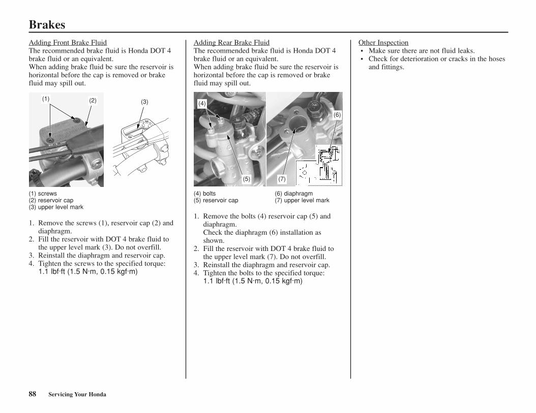
88 Servicing Your Honda
BrakesAdding Front Brake FluidThe recommended brake fluid is Honda DOT 4brake fluid or an equivalent.When adding brake fluid be sure the reservoir ishorizontal before the cap is removed or brakefluid may spill out.
(1) screws(2) reservoir cap(3) upper level mark
1. Remove the screws (1), reservoir cap (2) anddiaphragm.
2. Fill the reservoir with DOT 4 brake fluid tothe upper level mark (3). Do not overfill.
3. Reinstall the diaphragm and reservoir cap.4. Tighten the screws to the specified torque:
1.1 lbf·ft (1.5 N·m, 0.15 kgf·m)
Adding Rear Brake FluidThe recommended brake fluid is Honda DOT 4brake fluid or an equivalent.When adding brake fluid be sure the reservoir ishorizontal before the cap is removed or brakefluid may spill out.
(4) bolts (6) diaphragm(5) reservoir cap (7) upper level mark
1. Remove the bolts (4) reservoir cap (5) anddiaphragm.Check the diaphragm (6) installation asshown.
2. Fill the reservoir with DOT 4 brake fluid tothe upper level mark (7). Do not overfill.
3. Reinstall the diaphragm and reservoir cap. 4. Tighten the bolts to the specified torque:
1.1 lbf·ft (1.5 N·m, 0.15 kgf·m)
Other Inspection• Make sure there are not fluid leaks.• Check for deterioration or cracks in the hoses
and fittings.
(3)(2)(1)(4)
(5) (7)
(6)
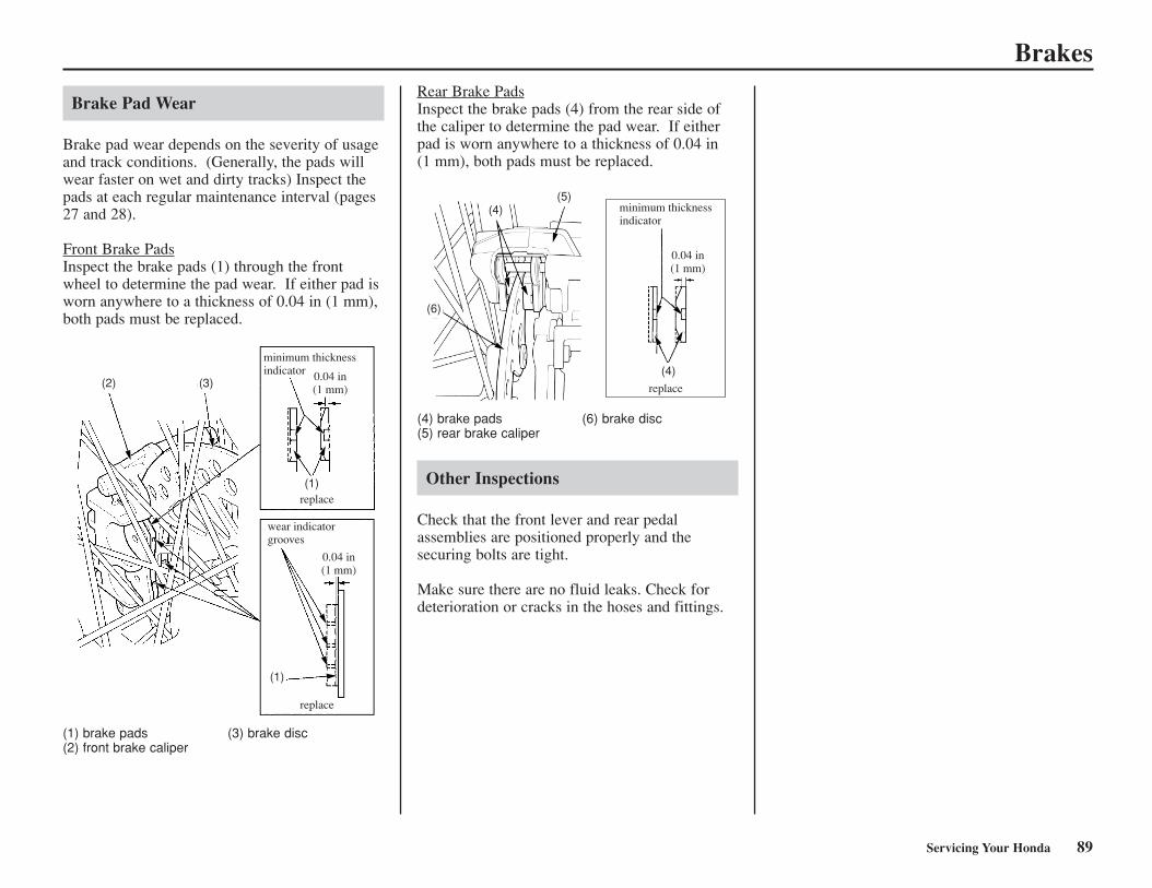
Servicing Your Honda 89
Brakes
Brake Pad Wear
Brake pad wear depends on the severity of usageand track conditions. (Generally, the pads willwear faster on wet and dirty tracks) Inspect thepads at each regular maintenance interval (pages27 and 28).
Front Brake PadsInspect the brake pads (1) through the frontwheel to determine the pad wear. If either pad isworn anywhere to a thickness of 0.04 in (1 mm),both pads must be replaced.
(1) brake pads (3) brake disc(2) front brake caliper
Rear Brake PadsInspect the brake pads (4) from the rear side ofthe caliper to determine the pad wear. If eitherpad is worn anywhere to a thickness of 0.04 in (1 mm), both pads must be replaced.
(4) brake pads (6) brake disc(5) rear brake caliper
Other Inspections
Check that the front lever and rear pedalassemblies are positioned properly and thesecuring bolts are tight.
Make sure there are no fluid leaks. Check fordeterioration or cracks in the hoses and fittings.
minimum thicknessindicator
wear indicatorgrooves
replace
replace
0.04 in(1 mm)
0.04 in(1 mm)
(2) (3)
(1)
(1)
replace
0.04 in(1 mm)
minimum thicknessindicator
(4)
(6)
(5)
(4)
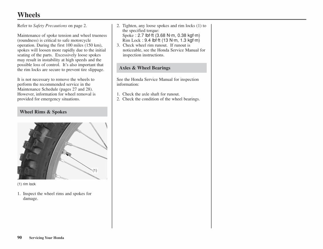
90 Servicing Your Honda
WheelsRefer to Safety Precautions on page 2.
Maintenance of spoke tension and wheel trueness(roundness) is critical to safe motorcycleoperation. During the first 100 miles (150 km),spokes will loosen more rapidly due to the initialseating of the parts. Excessively loose spokesmay result in instability at high speeds and thepossible loss of control. It’s also important thatthe rim locks are secure to prevent tire slippage.
It is not necessary to remove the wheels toperform the recommended service in theMaintenance Schedule (pages 27 and 28).However, information for wheel removal isprovided for emergency situations.
Wheel Rims & Spokes
(1) rim lock
1. Inspect the wheel rims and spokes fordamage.
2. Tighten, any loose spokes and rim locks (1) tothe specified torque:Spoke : 2.7 lbf·ft (3.68 N·m, 0.38 kgf·m)Rim Lock : 9.4 lbf·ft (13 N·m, 1.3 kgf·m)
3. Check wheel rim runout. If runout isnoticeable, see the Honda Service Manual forinspection instructions.
Axles & Wheel Bearings
See the Honda Service Manual for inspectioninformation:
1. Check the axle shaft for runout.2. Check the condition of the wheel bearings.
(1)
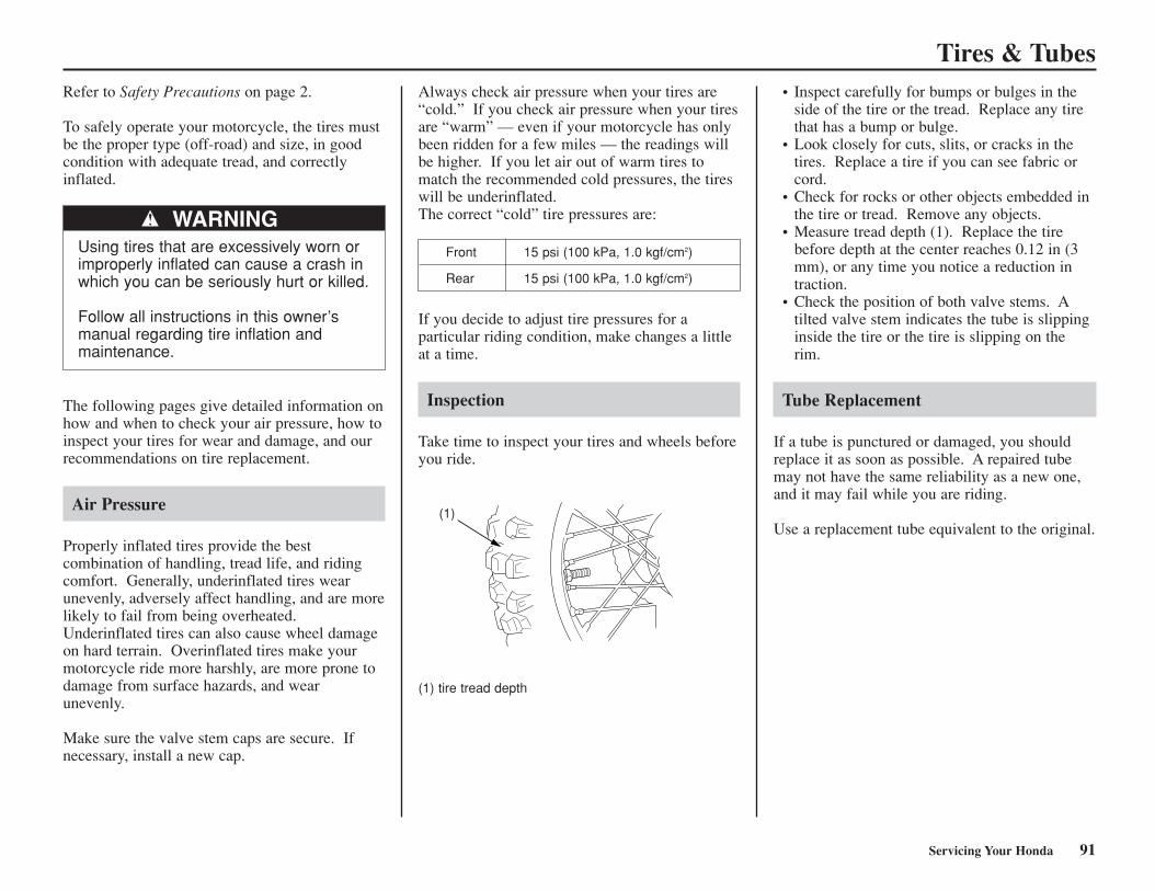
Servicing Your Honda 91
Tires & Tubes
WARNINGUsing tires that are excessively worn orimproperly inflated can cause a crash inwhich you can be seriously hurt or killed.
Follow all instructions in this owner’smanual regarding tire inflation andmaintenance.
Front 15 psi (100 kPa, 1.0 kgf/cm2)
Rear 15 psi (100 kPa, 1.0 kgf/cm2)
Refer to Safety Precautions on page 2.
To safely operate your motorcycle, the tires mustbe the proper type (off-road) and size, in goodcondition with adequate tread, and correctlyinflated.
The following pages give detailed information onhow and when to check your air pressure, how toinspect your tires for wear and damage, and ourrecommendations on tire replacement.
Air Pressure
Properly inflated tires provide the bestcombination of handling, tread life, and ridingcomfort. Generally, underinflated tires wearunevenly, adversely affect handling, and are morelikely to fail from being overheated.Underinflated tires can also cause wheel damageon hard terrain. Overinflated tires make yourmotorcycle ride more harshly, are more prone todamage from surface hazards, and wearunevenly.
Make sure the valve stem caps are secure. Ifnecessary, install a new cap.
Always check air pressure when your tires are“cold.” If you check air pressure when your tiresare “warm” — even if your motorcycle has onlybeen ridden for a few miles — the readings willbe higher. If you let air out of warm tires tomatch the recommended cold pressures, the tireswill be underinflated.The correct “cold” tire pressures are:
If you decide to adjust tire pressures for aparticular riding condition, make changes a littleat a time.
Inspection
Take time to inspect your tires and wheels beforeyou ride.
• Inspect carefully for bumps or bulges in theside of the tire or the tread. Replace any tirethat has a bump or bulge.
• Look closely for cuts, slits, or cracks in thetires. Replace a tire if you can see fabric orcord.
• Check for rocks or other objects embedded inthe tire or tread. Remove any objects.
• Measure tread depth (1). Replace the tirebefore depth at the center reaches 0.12 in (3mm), or any time you notice a reduction intraction.
• Check the position of both valve stems. Atilted valve stem indicates the tube is slippinginside the tire or the tire is slipping on therim.
Tube Replacement
If a tube is punctured or damaged, you shouldreplace it as soon as possible. A repaired tubemay not have the same reliability as a new one,and it may fail while you are riding.
Use a replacement tube equivalent to the original.(1)
(1) tire tread depth
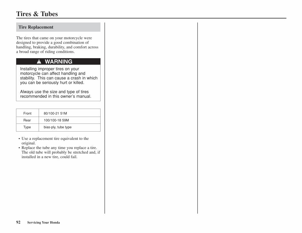
92 Servicing Your Honda
Tires & Tubes
Tire Replacement
The tires that came on your motorcycle weredesigned to provide a good combination of handling, braking, durability, and comfort acrossa broad range of riding conditions.
WARNINGInstalling improper tires on yourmotorcycle can affect handling andstability. This can cause a crash in whichyou can be seriously hurt or killed.
Always use the size and type of tiresrecommended in this owner’s manual.
Front 80/100-21 51M
Rear 100/100-18 59M
Type bias-ply, tube type
• Use a replacement tire equivalent to theoriginal.
• Replace the tube any time you replace a tire.The old tube will probably be stretched and, ifinstalled in a new tire, could fail.
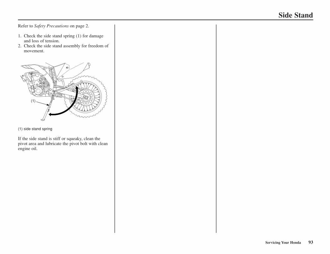
Side Stand
Servicing Your Honda 93
Refer to Safety Precautions on page 2.
1. Check the side stand spring (1) for damageand loss of tension.
2. Check the side stand assembly for freedom ofmovement.
(1) side stand spring
If the side stand is stiff or squeaky, clean thepivot area and lubricate the pivot bolt with cleanengine oil.
(1)
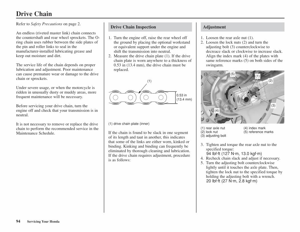
94 Servicing Your Honda
Drive ChainRefer to Safety Precautions on page 2.
An endless (riveted master link) chain connectsthe countershaft and rear wheel sprockets. The O-ring chain uses rubber between the side plates ofthe pin and roller links to seal in themanufacturer-installed lubricating grease andkeep out moisture and dirt.
The service life of the chain depends on properlubrication and adjustment. Poor maintenancecan cause premature wear or damage to the drivechain or sprockets.
Under severe usage, or when the motorcycle isridden in unusually dusty or muddy areas, morefrequent maintenance will be necessary.
Before servicing your drive chain, turn theengine off and check that your transmission is inneutral.
It is not necessary to remove or replace the drivechain to perform the recommended service in theMaintenance Schedule.
Drive Chain Inspection
1. Turn the engine off, raise the rear wheel offthe ground by placing the optional workstandor equivalent support under the engine andshift the transmission into neutral.
2. Measure the drive chain plate (1). If the drivechain plate is worn anywhere to a thickness of0.53 in (13.4 mm), the drive chain must bereplaced.
(1) drive chain plate (inner)
If the chain is found to be slack in one segmentof its length and taut in another, this indicatesthat some of the links are either worn, kinked orbinding. Kinking and binding can frequently beeliminated by thorough cleaning and lubrication.If the drive chain requires adjustment, procedureis as follows:
Adjustment
1. Loosen the rear axle nut (1).2. Loosen the lock nuts (2) and turn the
adjusting bolt (3) counterclockwise todecreace slack or clockwise to increase slack.Align the index mark (4) of the plates withsame reference marks (5) on both sides of theswingarm.
(1) rear axle nut (4) index mark(2) lock nut (5) reference marks(3) adjusting bolt
3. Tighten and torque the rear axle nut to thespecified torque:94 lbf·ft (127 N·m, 13.0 kgf·m)
4. Recheck chain slack and adjust if necessary.5. Turn the adjusting bolt counterclockwise
lightly until it touches the axle plate. Then,tighten the lock nut to the specified torque byholding the adjusting bolt with a wrench.20 lbf·ft (27 N·m, 2.8 kgf·m)
0.53 in(13.4 mm)
(1)
(5)
(4)
(3)
(2)(1)
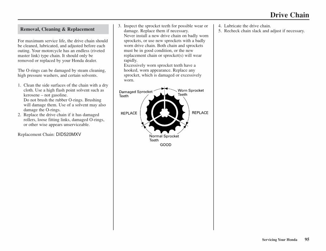
Servicing Your Honda 95
Drive Chain
Removal, Cleaning & Replacement
For maximum service life, the drive chain shouldbe cleaned, lubricated, and adjusted before eachouting. Your motorcycle has an endless (rivetedmaster link) type chain. It should only beremoved or replaced by your Honda dealer.
The O-rings can be damaged by steam cleaning,high pressure washers, and certain solvents.
1. Clean the side surfaces of the chain with a drycloth. Use a high flash point solvent such askerosene – not gasoline.Do not brush the rubber O-rings. Brushingwill damage them. Use of a solvent may alsodamage the O-rings.
2. Replace the drive chain if it has damagedrollers, loose fitting links, damaged O-rings,or other wise appears unserviceable.
Replacement Chain: DID520MXV
3. Inspect the sprocket teeth for possible wear ordamage. Replace them if necessary.Never install a new drive chain on badly wornsprockets, or use new sprockets with a badlyworn drive chain. Both chain and sprocketsmust be in good condition, or the newreplacement chain or sprocket(s) will wearrapidly.Excessively worn sprocket teeth have ahooked, worn appearance. Replace anysprocket, which is damaged or excessivelyworn.
4. Lubricate the drive chain.5. Recheck chain slack and adjust if necessary.
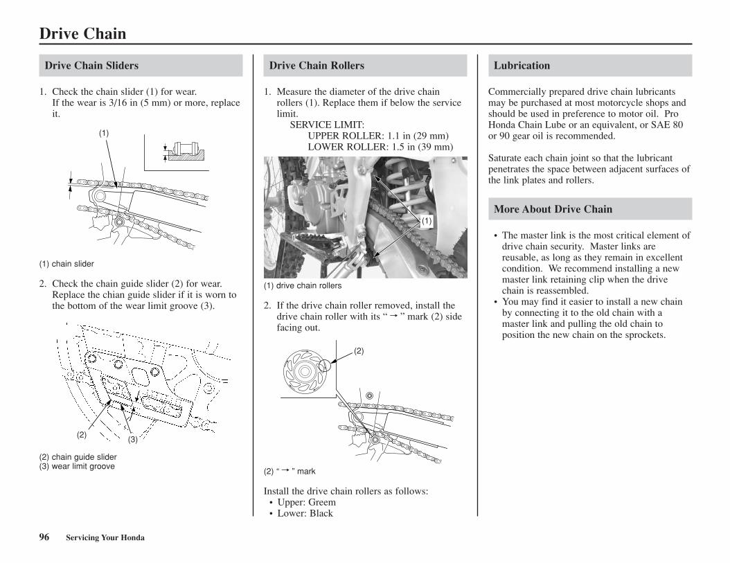
96 Servicing Your Honda
Drive Chain
Drive Chain Sliders
1. Check the chain slider (1) for wear.If the wear is 3/16 in (5 mm) or more, replaceit.
Lubrication
Commercially prepared drive chain lubricantsmay be purchased at most motorcycle shops andshould be used in preference to motor oil. ProHonda Chain Lube or an equivalent, or SAE 80or 90 gear oil is recommended.
Saturate each chain joint so that the lubricantpenetrates the space between adjacent surfaces ofthe link plates and rollers.
More About Drive Chain
• The master link is the most critical element ofdrive chain security. Master links arereusable, as long as they remain in excellentcondition. We recommend installing a newmaster link retaining clip when the drivechain is reassembled.
• You may find it easier to install a new chainby connecting it to the old chain with amaster link and pulling the old chain toposition the new chain on the sprockets.
(1) chain slider
2. Check the chain guide slider (2) for wear.Replace the chian guide slider if it is worn tothe bottom of the wear limit groove (3).
(2) chain guide slider(3) wear limit groove
Drive Chain Rollers
1. Measure the diameter of the drive chainrollers (1). Replace them if below the servicelimit.
SERVICE LIMIT:UPPER ROLLER: 1.1 in (29 mm)LOWER ROLLER: 1.5 in (39 mm)
(1) drive chain rollers
2. If the drive chain roller removed, install thedrive chain roller with its “ ” mark (2) sidefacing out.
(2) “ ” mark
Install the drive chain rollers as follows:• Upper: Greem• Lower: Black
(1)
(2) (3)
(1)
(2)
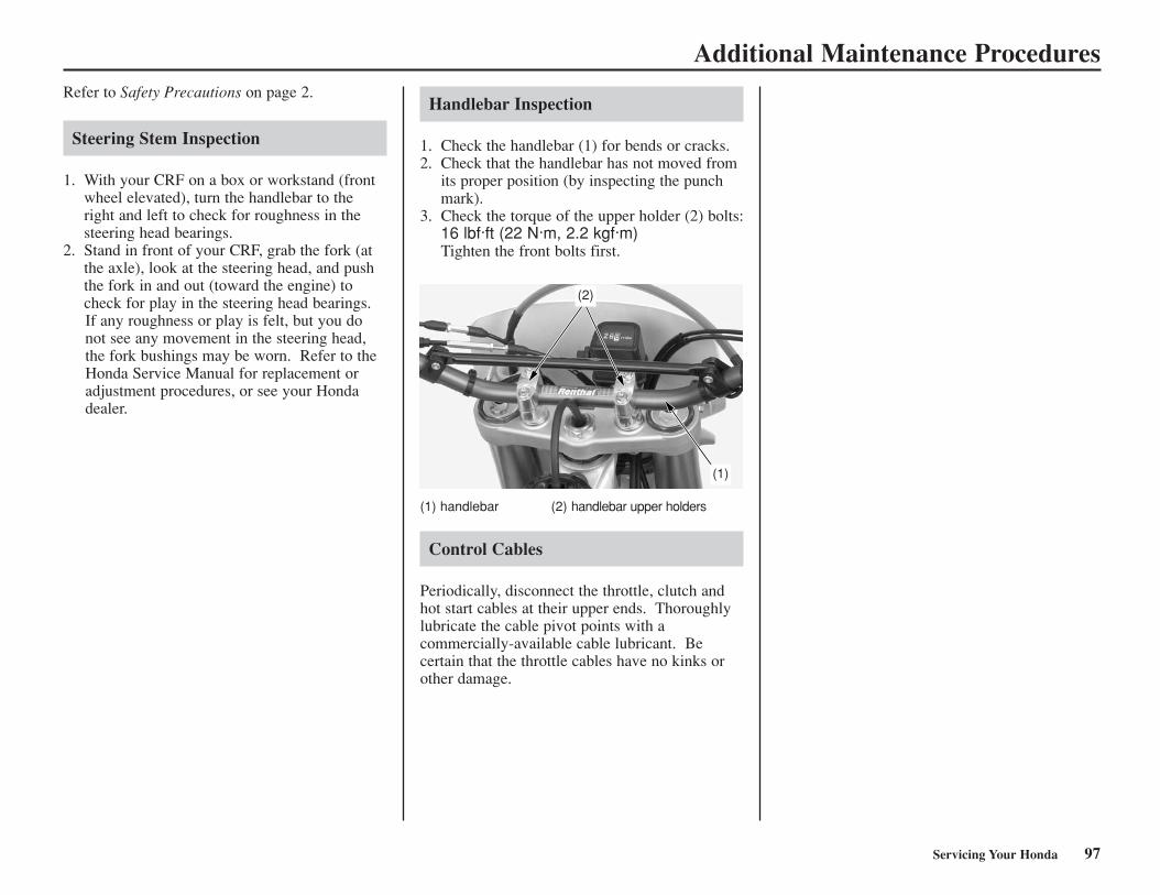
Servicing Your Honda 97
Additional Maintenance ProceduresRefer to Safety Precautions on page 2.
Steering Stem Inspection
1. With your CRF on a box or workstand (frontwheel elevated), turn the handlebar to theright and left to check for roughness in thesteering head bearings.
2. Stand in front of your CRF, grab the fork (atthe axle), look at the steering head, and pushthe fork in and out (toward the engine) tocheck for play in the steering head bearings.If any roughness or play is felt, but you donot see any movement in the steering head,the fork bushings may be worn. Refer to theHonda Service Manual for replacement oradjustment procedures, or see your Hondadealer.
Handlebar Inspection
1. Check the handlebar (1) for bends or cracks.2. Check that the handlebar has not moved from
its proper position (by inspecting the punchmark).
3. Check the torque of the upper holder (2) bolts:16 lbf·ft (22 N·m, 2.2 kgf·m)Tighten the front bolts first.
(1) handlebar (2) handlebar upper holders
Control Cables
Periodically, disconnect the throttle, clutch andhot start cables at their upper ends. Thoroughlylubricate the cable pivot points with acommercially-available cable lubricant. Becertain that the throttle cables have no kinks orother damage.
(2)
(1)
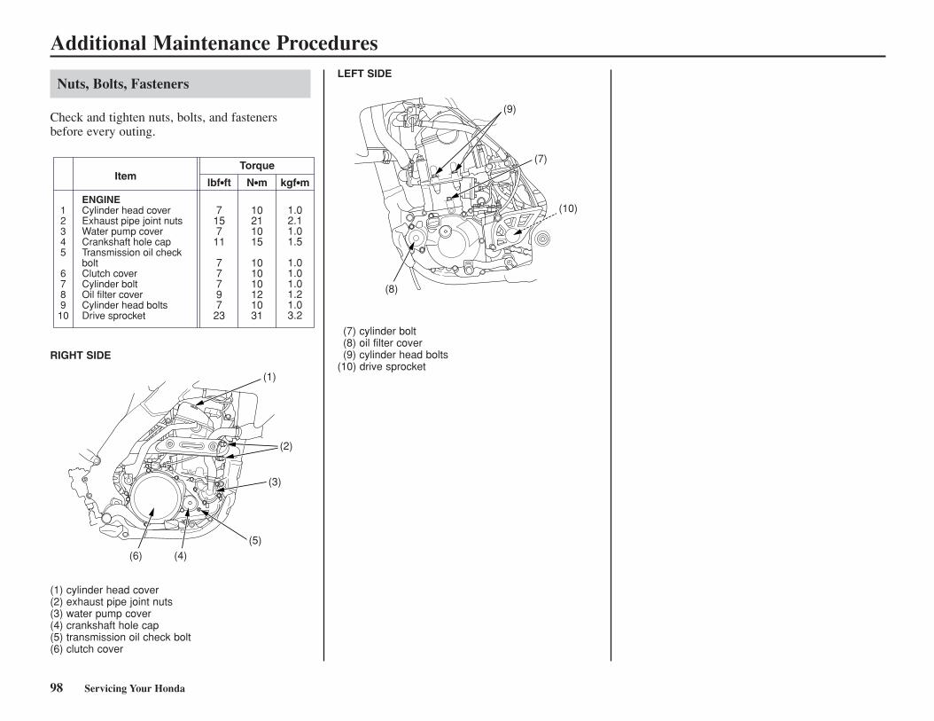
98 Servicing Your Honda
Additional Maintenance Procedures
Nuts, Bolts, Fasteners
Check and tighten nuts, bolts, and fastenersbefore every outing.
Item
12345
678910
ENGINECylinder head coverExhaust pipe joint nutsWater pump coverCrankshaft hole capTransmission oil check boltClutch coverCylinder boltOil filter coverCylinder head boltsDrive sprocket
Torque
lbf•ft N•m kgf•m
7157
11
77797
23
10211015
101010121031
1.02.11.01.5
1.01.01.01.21.03.2
(1) cylinder head cover(2) exhaust pipe joint nuts(3) water pump cover(4) crankshaft hole cap(5) transmission oil check bolt(6) clutch cover
(1)
(2)
(3)
(5)(4)(6)
(9)
(8)
(7)
(10)
RIGHT SIDE
LEFT SIDE
(7) cylinder bolt(8) oil filter cover(9) cylinder head bolts
(10) drive sprocket
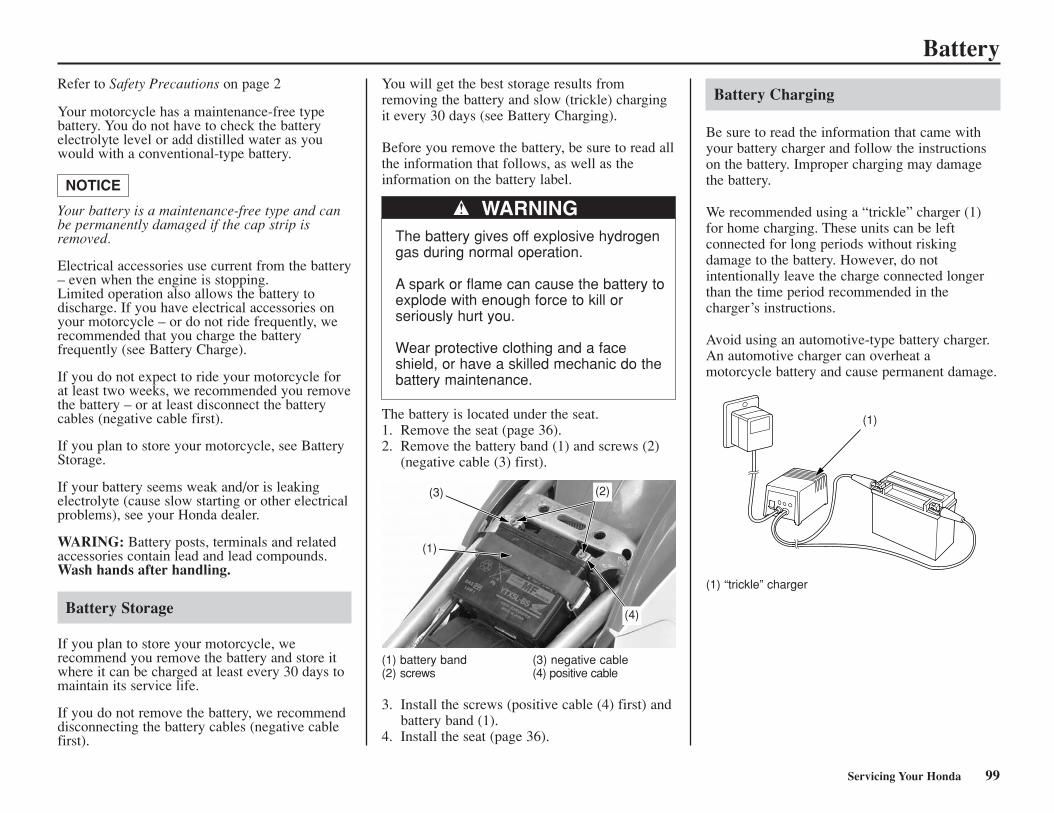
Battery
Servicing Your Honda 99
Refer to Safety Precautions on page 2
Your motorcycle has a maintenance-free typebattery. You do not have to check the batteryelectrolyte level or add distilled water as youwould with a conventional-type battery.
Your battery is a maintenance-free type and canbe permanently damaged if the cap strip isremoved.
Electrical accessories use current from the battery– even when the engine is stopping.Limited operation also allows the battery todischarge. If you have electrical accessories onyour motorcycle – or do not ride frequently, werecommended that you charge the batteryfrequently (see Battery Charge).
If you do not expect to ride your motorcycle forat least two weeks, we recommended you removethe battery – or at least disconnect the batterycables (negative cable first).
If you plan to store your motorcycle, see BatteryStorage.
If your battery seems weak and/or is leakingelectrolyte (cause slow starting or other electricalproblems), see your Honda dealer.
WARING: Battery posts, terminals and relatedaccessories contain lead and lead compounds.Wash hands after handling.
Battery Storage
If you plan to store your motorcycle, werecommend you remove the battery and store itwhere it can be charged at least every 30 days tomaintain its service life.
If you do not remove the battery, we recommenddisconnecting the battery cables (negative cablefirst).
NOTICE
You will get the best storage results fromremoving the battery and slow (trickle) chargingit every 30 days (see Battery Charging).
Before you remove the battery, be sure to read allthe information that follows, as well as theinformation on the battery label.
WARNINGThe battery gives off explosive hydrogengas during normal operation.
A spark or flame can cause the battery toexplode with enough force to kill orseriously hurt you.
Wear protective clothing and a faceshield, or have a skilled mechanic do thebattery maintenance.
The battery is located under the seat.1. Remove the seat (page 36).2. Remove the battery band (1) and screws (2)
(negative cable (3) first).
(1) battery band (3) negative cable (2) screws (4) positive cable
3. Install the screws (positive cable (4) first) andbattery band (1).
4. Install the seat (page 36).
Battery Charging
Be sure to read the information that came withyour battery charger and follow the instructionson the battery. Improper charging may damagethe battery.
We recommended using a “trickle” charger (1)for home charging. These units can be leftconnected for long periods without riskingdamage to the battery. However, do notintentionally leave the charge connected longerthan the time period recommended in thecharger’s instructions.
Avoid using an automotive-type battery charger.An automotive charger can overheat amotorcycle battery and cause permanent damage.
(1) “trickle” charger
(3)
(4)
(2)
(1)
(1)
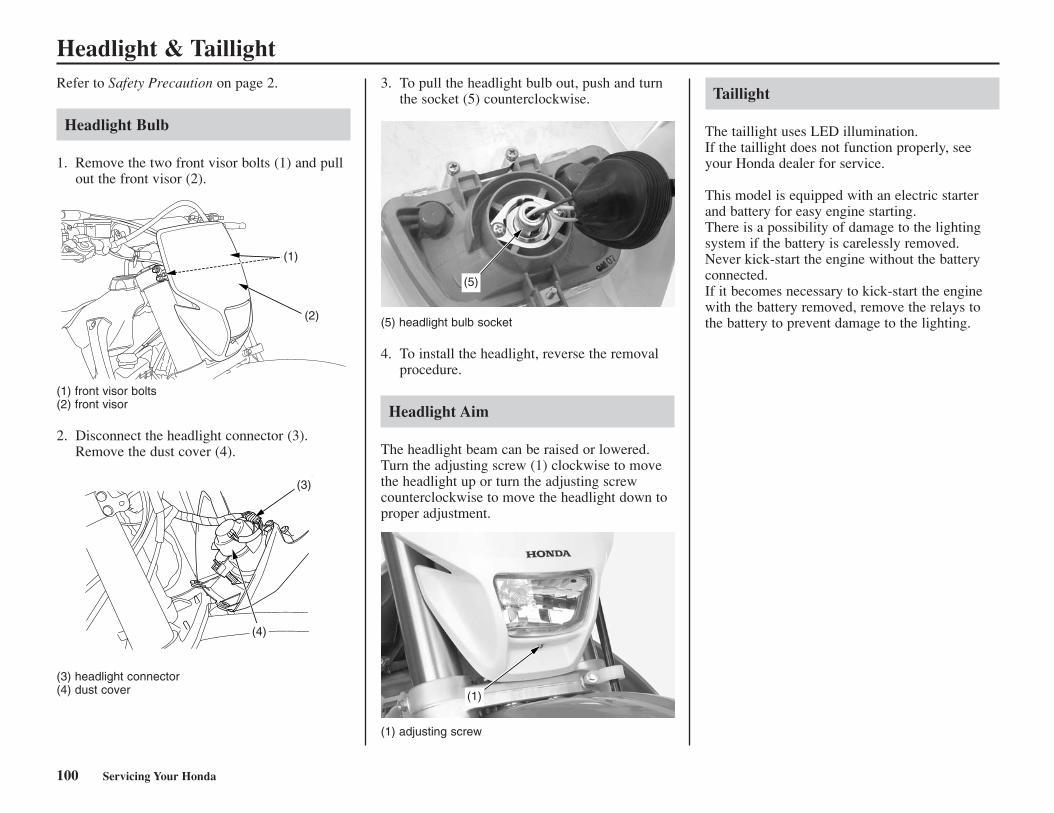
Headlight & Taillight
100 Servicing Your Honda
Refer to Safety Precaution on page 2.
Headlight Bulb
1. Remove the two front visor bolts (1) and pullout the front visor (2).
(1) front visor bolts(2) front visor
2. Disconnect the headlight connector (3).Remove the dust cover (4).
(3) headlight connector(4) dust cover
3. To pull the headlight bulb out, push and turnthe socket (5) counterclockwise.
(5) headlight bulb socket
4. To install the headlight, reverse the removalprocedure.
Headlight Aim
The headlight beam can be raised or lowered.Turn the adjusting screw (1) clockwise to movethe headlight up or turn the adjusting screwcounterclockwise to move the headlight down toproper adjustment.
Taillight
The taillight uses LED illumination.If the taillight does not function properly, seeyour Honda dealer for service.
This model is equipped with an electric starterand battery for easy engine starting.There is a possibility of damage to the lightingsystem if the battery is carelessly removed.Never kick-start the engine without the batteryconnected.If it becomes necessary to kick-start the enginewith the battery removed, remove the relays tothe battery to prevent damage to the lighting.(2)
(1)
(3)
(4)
(5)
(1)
(1) adjusting screw
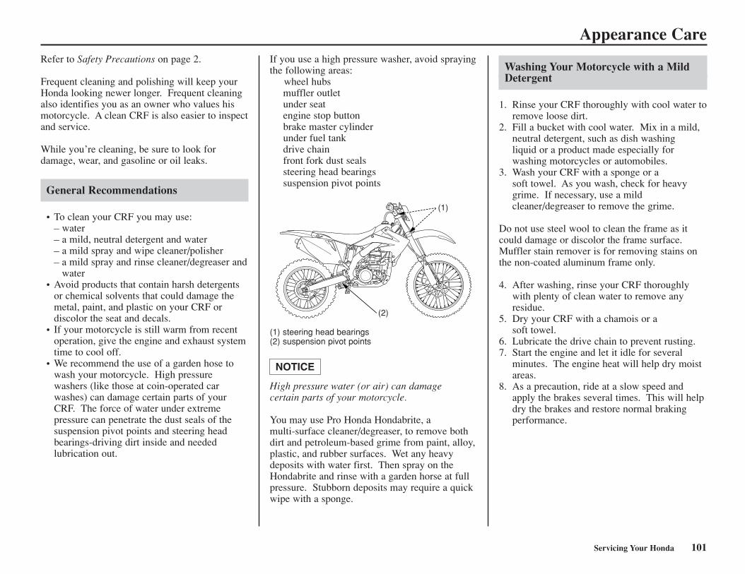
Servicing Your Honda 101
Appearance CareRefer to Safety Precautions on page 2.
Frequent cleaning and polishing will keep yourHonda looking newer longer. Frequent cleaningalso identifies you as an owner who values hismotorcycle. A clean CRF is also easier to inspectand service.
While you’re cleaning, be sure to look for damage, wear, and gasoline or oil leaks.
General Recommendations
• To clean your CRF you may use:– water– a mild, neutral detergent and water– a mild spray and wipe cleaner/polisher– a mild spray and rinse cleaner/degreaser and
water• Avoid products that contain harsh detergents
or chemical solvents that could damage themetal, paint, and plastic on your CRF or discolor the seat and decals.
• If your motorcycle is still warm from recentoperation, give the engine and exhaust systemtime to cool off.
• We recommend the use of a garden hose towash your motorcycle. High pressure washers (like those at coin-operated car washes) can damage certain parts of yourCRF. The force of water under extremepressure can penetrate the dust seals of thesuspension pivot points and steering headbearings-driving dirt inside and neededlubrication out.
If you use a high pressure washer, avoid sprayingthe following areas:
wheel hubsmuffler outletunder seatengine stop buttonbrake master cylinderunder fuel tankdrive chainfront fork dust sealssteering head bearingssuspension pivot points
(1) steering head bearings(2) suspension pivot points
High pressure water (or air) can damage certain parts of your motorcycle.
You may use Pro Honda Hondabrite, a multi-surface cleaner/degreaser, to remove bothdirt and petroleum-based grime from paint, alloy,plastic, and rubber surfaces. Wet any heavydeposits with water first. Then spray on theHondabrite and rinse with a garden horse at fullpressure. Stubborn deposits may require a quickwipe with a sponge.
NOTICE
Washing Your Motorcycle with a MildDetergent
1. Rinse your CRF thoroughly with cool water toremove loose dirt.
2. Fill a bucket with cool water. Mix in a mild,neutral detergent, such as dish washing liquid or a product made especially for washing motorcycles or automobiles.
3. Wash your CRF with a sponge or a soft towel. As you wash, check for heavygrime. If necessary, use a mildcleaner/degreaser to remove the grime.
Do not use steel wool to clean the frame as itcould damage or discolor the frame surface.Muffler stain remover is for removing stains onthe non-coated aluminum frame only.
4. After washing, rinse your CRF thoroughlywith plenty of clean water to remove anyresidue.
5. Dry your CRF with a chamois or a soft towel.
6. Lubricate the drive chain to prevent rusting.7. Start the engine and let it idle for several
minutes. The engine heat will help dry moistareas.
8. As a precaution, ride at a slow speed andapply the brakes several times. This will helpdry the brakes and restore normal brakingperformance.
(1)
(2)
102 Servicing Your Honda
Appearance Care
Condensation Control
Some condensation can form within thetransmission cavity as well. This is natural andjust one more reason you should change theengine and transmission oil often.
After Cleaning Lubrication
There are some things you should do just afterwashing your CRF to help prevent rust andcorrosion.
Once your CRF is clean and dry, you shouldprotect any bare steel from rusting by applying alight coating of a rust-inhibitor. Lubricate thedrive chain and drive sprocket after removingand thoroughly cleaning in solvent. Be sure thechain is wiped clean and is dry before applyingthe chain lube.
Follow the suggestions given in the pages of thismanual for lubricating items such as the brakeand clutch lever pivot points and footpeg pivotpins.
Aluminum Frame Maintenance
Aluminum corrodes when it comes in contactwith dust, mud and road salt.
To remove stains, use Scotch Brite Hand Pad#7447 (maroon) or an equivalent.Wet the pad and polish the surface using strokesparallel to the length of the frame.
Clean the frame using a wet sponge and a milddetergent, then rinse well with clean water. Drythe frame with a soft clean cloth, using strokesparallel to the length of the frame.
Do not use steel wool to clean the frame as itcould damage or discolor the frame surface.Muffler stain remover (Scotch Brite Hand Pad#7447-maroon) is for removing stains on thenon-coated aluminum frame only.
NOTICE
Exhaust Pipe Maintenance
The exhaust pipe is stainless steel, but maybecame stained by oil or mud.
Remove heat stains with a liquid kitchenabrasive.
This section tells you how to fine tune your CRFfor maximum competition performance.
Initial suspension adjustments should beperformed after a minimum of two hours of easybreak-in time.
Optional front and rear suspension springs areavailable in both firmer and softer than standardrates, in order to tailor your CRF specifically foryour weight, riding style and course conditions.
Follow the instructions given in the rearsuspension sag setting section of RearSuspension Adjustments to determine if yourcombined rider and sprung machine weight (riderfully dressed for competition and machinecoolant, oil and fuel levels ready for competition)requires an optional firmer or softer rear spring.The need for either optional rear spring may needto be balanced by installing the optional forksprings of a similar rate.
Front Suspension Adjustments.........................104 Rear Suspension Adjustments ..........................118Suspension Adjustments for Track Conditions
................................................................122Suspension Adjustments Guidelines ................123Carburetor Adjustments & Tuning Tips...........126Chassis Adjustments.........................................133Gearing .............................................................134Tire Selection for Track Conditions.................135Personal Fit Adjustments .................................136
Adjustments for Competition 103
Adjustments for Competition
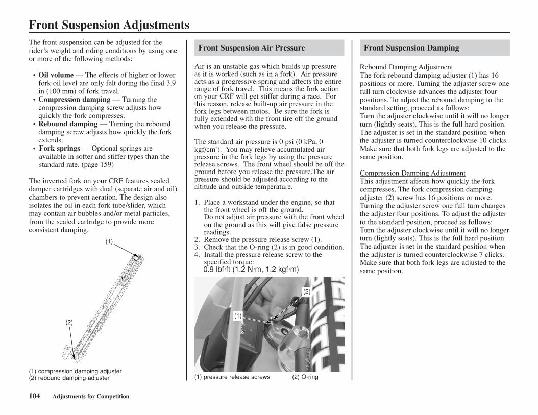
104 Adjustments for Competition
Front Suspension AdjustmentsThe front suspension can be adjusted for therider’s weight and riding conditions by using oneor more of the following methods:
• Oil volume — The effects of higher or lowerfork oil level are only felt during the final 3.9in (100 mm) of fork travel.
• Compression damping — Turning thecompression damping screw adjusts howquickly the fork compresses.
• Rebound damping — Turning the rebounddamping screw adjusts how quickly the forkextends.
• Fork springs — Optional springs areavailable in softer and stiffer types than thestandard rate. (page 159)
The inverted fork on your CRF features sealeddamper cartridges with dual (separate air and oil)chambers to prevent aeration. The design alsoisolates the oil in each fork tube/slider, whichmay contain air bubbles and/or metal particles,from the sealed cartridge to provide moreconsistent damping.
(1) compression damping adjuster(2) rebound damping adjuster
(1)
(2)
Front Suspension Air Pressure
Air is an unstable gas which builds up pressureas it is worked (such as in a fork). Air pressureacts as a progressive spring and affects the entirerange of fork travel. This means the fork actionon your CRF will get stiffer during a race. Forthis reason, release built-up air pressure in thefork legs between motos. Be sure the fork isfully extended with the front tire off the groundwhen you release the pressure.
The standard air pressure is 0 psi (0 kPa, 0kgf/cm2). You may relieve accumulated airpressure in the fork legs by using the pressurerelease screws. The front wheel should be off theground before you release the pressure.The airpressure should be adjusted according to thealtitude and outside temperature.
1. Place a workstand under the engine, so thatthe front wheel is off the ground.Do not adjust air pressure with the front wheelon the ground as this will give false pressurereadings.
2. Remove the pressure release screw (1).3. Check that the O-ring (2) is in good condition.4. Install the pressure release screw to the
specified torque:0.9 lbf·ft (1.2 N·m, 1.2 kgf·m)
(1) pressure release screws (2) O-ring
(2)
(1)
Front Suspension Damping
Rebound Damping AdjustmentThe fork rebound damping adjuster (1) has 16positions or more. Turning the adjuster screw onefull turn clockwise advances the adjuster fourpositions. To adjust the rebound damping to thestandard setting, proceed as follows: Turn the adjuster clockwise until it will no longerturn (lightly seats). This is the full hard position. The adjuster is set in the standard position whenthe adjuster is turned counterclockwise 10 clicks. Make sure that both fork legs are adjusted to thesame position.
Compression Damping AdjustmentThis adjustment affects how quickly the forkcompresses. The fork compression dampingadjuster (2) screw has 16 positions or more.Turning the adjuster screw one full turn changesthe adjuster four positions. To adjust the adjusterto the standard position, proceed as follows: Turn the adjuster clockwise until it will no longerturn (lightly seats). This is the full hard position.The adjuster is set in the standard position whenthe adjuster is turned counterclockwise 7 clicks.Make sure that both fork legs are adjusted to thesame position.
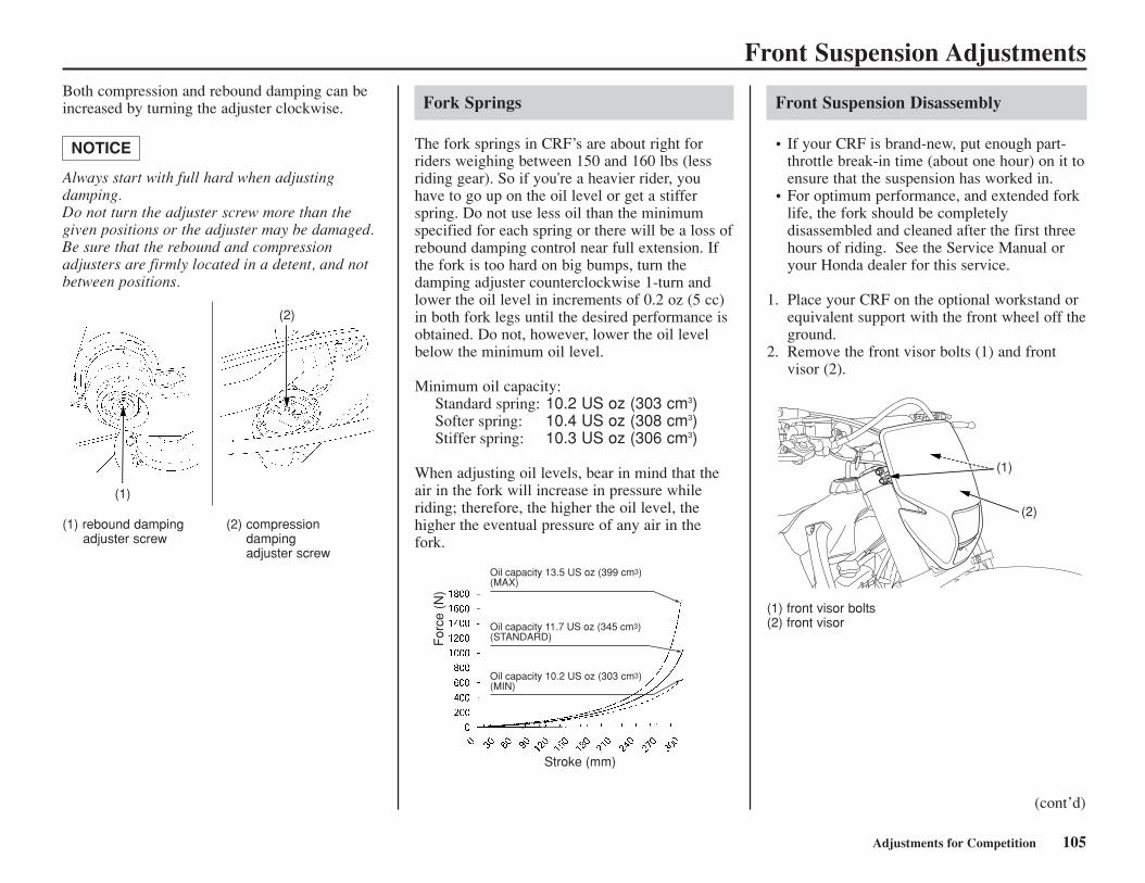
Adjustments for Competition 105
Front Suspension AdjustmentsBoth compression and rebound damping can beincreased by turning the adjuster clockwise.
Always start with full hard when adjustingdamping. Do not turn the adjuster screw more than thegiven positions or the adjuster may be damaged. Be sure that the rebound and compressionadjusters are firmly located in a detent, and notbetween positions.
NOTICE
Front Suspension Disassembly
• If your CRF is brand-new, put enough part-throttle break-in time (about one hour) on it toensure that the suspension has worked in.
• For optimum performance, and extended forklife, the fork should be completelydisassembled and cleaned after the first threehours of riding. See the Service Manual oryour Honda dealer for this service.
1. Place your CRF on the optional workstand orequivalent support with the front wheel off theground.
2. Remove the front visor bolts (1) and frontvisor (2).
Fork Springs
The fork springs in CRF’s are about right forriders weighing between 150 and 160 lbs (lessriding gear). So if you're a heavier rider, youhave to go up on the oil level or get a stifferspring. Do not use less oil than the minimumspecified for each spring or there will be a loss ofrebound damping control near full extension. Ifthe fork is too hard on big bumps, turn thedamping adjuster counterclockwise 1-turn andlower the oil level in increments of 0.2 oz (5 cc)in both fork legs until the desired performance isobtained. Do not, however, lower the oil levelbelow the minimum oil level.
Minimum oil capacity:Standard spring: 10.2 US oz (303 cm3)Softer spring: 10.4 US oz (308 cm3) Stiffer spring: 10.3 US oz (306 cm3)
When adjusting oil levels, bear in mind that theair in the fork will increase in pressure whileriding; therefore, the higher the oil level, thehigher the eventual pressure of any air in thefork.
(1) rebound damping (2) compressionadjuster screw damping
adjuster screw
(1)
(2)
For
ce (
N)
Stroke (mm)
Oil capacity 13.5 US oz (399 cm3)(MAX)
Oil capacity 11.7 US oz (345 cm3)(STANDARD)
Oil capacity 10.2 US oz (303 cm3)(MIN)
(1)
(2)
(1) front visor bolts(2) front visor
(cont’d)
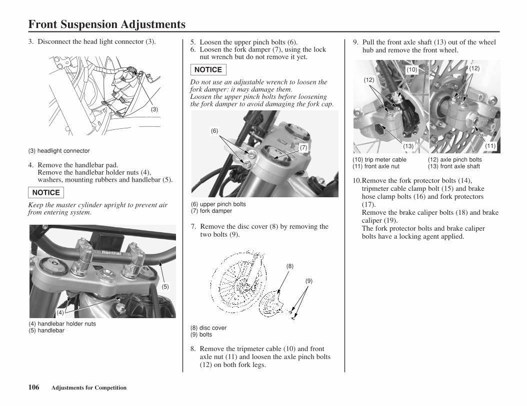
Front Suspension Adjustments
106 Adjustments for Competition
(3) headlight connector
4. Remove the handlebar pad.Remove the handlebar holder nuts (4),washers, mounting rubbers and handlebar (5).
Keep the master cylinder upright to prevent airfrom entering system.
NOTICE
5. Loosen the upper pinch bolts (6). 6. Loosen the fork damper (7), using the lock
nut wrench but do not remove it yet.
Do not use an adjustable wrench to loosen thefork damper: it may damage them.Loosen the upper pinch bolts before looseningthe fork damper to avoid damaging the fork cap.
NOTICE
(8) disc cover (9) bolts
8. Remove the tripmeter cable (10) and frontaxle nut (11) and loosen the axle pinch bolts(12) on both fork legs.
(6) upper pinch bolts(7) fork damper
7. Remove the disc cover (8) by removing thetwo bolts (9).
(8)
(9)
3. Disconnect the head light connector (3). 9. Pull the front axle shaft (13) out of the wheelhub and remove the front wheel.
(10) trip meter cable (12) axle pinch bolts(11) front axle nut (13) front axle shaft
10.Remove the fork protector bolts (14),tripmeter cable clamp bolt (15) and brakehose clamp bolts (16) and fork protectors(17).Remove the brake caliper bolts (18) and brakecaliper (19).The fork protector bolts and brake caliperbolts have a locking agent applied.
(3)
(5)
(4)
(6)
(7)
(12)
(13)
(10) (12)
(11)
(4) handlebar holder nuts (5) handlebar
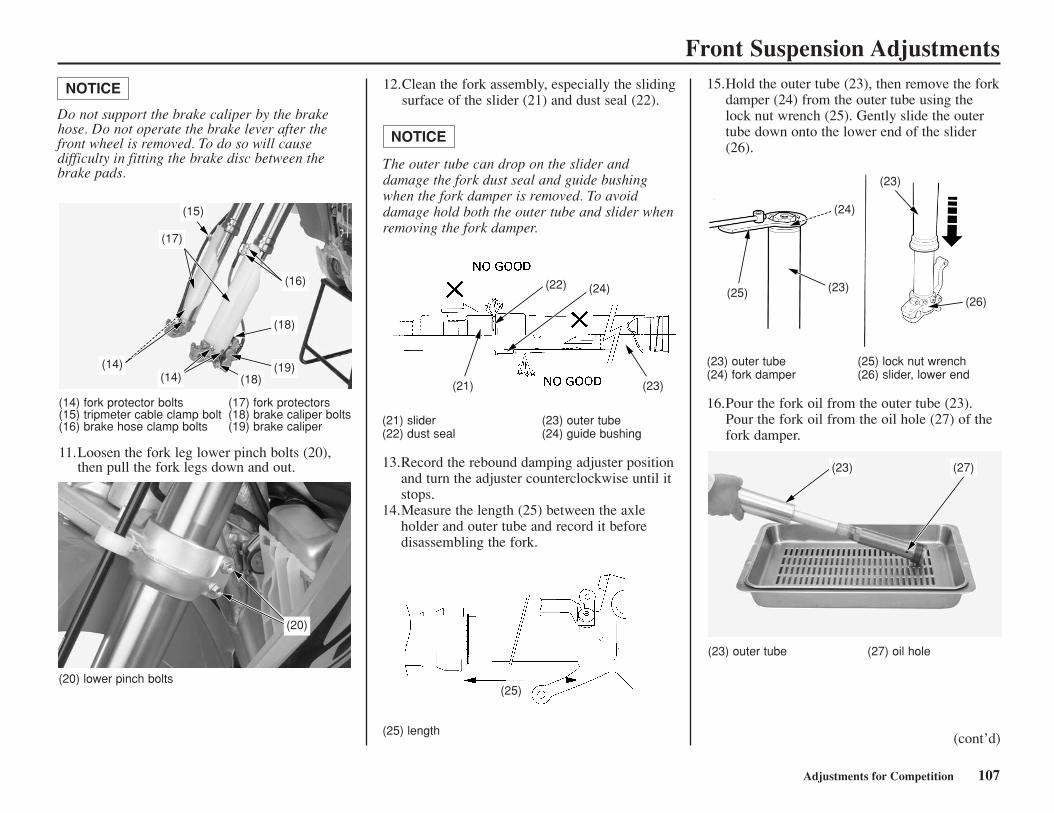
Front Suspension Adjustments
Adjustments for Competition 107
(20) lower pinch bolts
15.Hold the outer tube (23), then remove the forkdamper (24) from the outer tube using thelock nut wrench (25). Gently slide the outertube down onto the lower end of the slider(26).
12.Clean the fork assembly, especially the slidingsurface of the slider (21) and dust seal (22).
The outer tube can drop on the slider anddamage the fork dust seal and guide bushingwhen the fork damper is removed. To avoiddamage hold both the outer tube and slider whenremoving the fork damper.
NOTICE
(21) slider (23) outer tube(22) dust seal (24) guide bushing
13.Record the rebound damping adjuster positionand turn the adjuster counterclockwise until itstops.
14.Measure the length (25) between the axleholder and outer tube and record it beforedisassembling the fork.
(23) outer tube (25) lock nut wrench(24) fork damper (26) slider, lower end
16.Pour the fork oil from the outer tube (23).Pour the fork oil from the oil hole (27) of thefork damper.
(23) outer tube (27) oil hole
(25) length
(21)
(22) (24)
(23)
(25)
(25) (23)(26)
(23)
(24)
(23) (27)
(14) fork protector bolts (17) fork protectors(15) tripmeter cable clamp bolt (18) brake caliper bolts(16) brake hose clamp bolts (19) brake caliper
11.Loosen the fork leg lower pinch bolts (20),then pull the fork legs down and out.
(17)
(15)
(16)
(18)
(19)(14)(14) (18)
(20)
Do not support the brake caliper by the brakehose. Do not operate the brake lever after thefront wheel is removed. To do so will causedifficulty in fitting the brake disc between thebrake pads.
NOTICE
(cont’d)
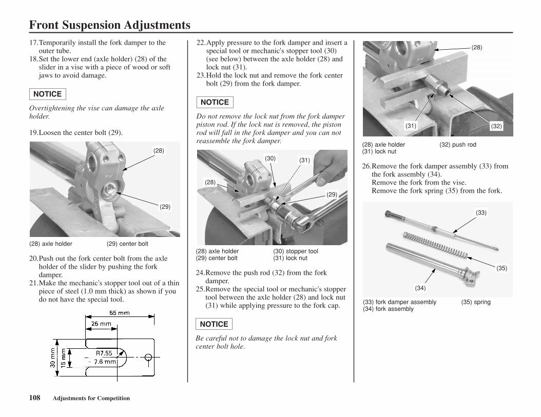
Front Suspension Adjustments
108 Adjustments for Competition
22.Apply pressure to the fork damper and insert aspecial tool or mechanic's stopper tool (30)(see below) between the axle holder (28) andlock nut (31).
23.Hold the lock nut and remove the fork centerbolt (29) from the fork damper.
Do not remove the lock nut from the fork damperpiston rod. If the lock nut is removed, the pistonrod will fall in the fork damper and you can notreassemble the fork damper.
NOTICE
(28) axle holder (30) stopper tool(29) center bolt (31) lock nut
24.Remove the push rod (32) from the forkdamper.
25.Remove the special tool or mechanic's stoppertool between the axle holder (28) and lock nut(31) while applying pressure to the fork cap.
Be careful not to damage the lock nut and forkcenter bolt hole.
NOTICE
(28) axle holder (32) push rod(31) lock nut
26.Remove the fork damper assembly (33) fromthe fork assembly (34). Remove the fork from the vise. Remove the fork spring (35) from the fork.
(33) fork damper assembly (35) spring(34) fork assembly
(28)
(30) (31)
(29)
(28)
(32)(31)
(33)
(35)
(34)
17.Temporarily install the fork damper to theouter tube.
18.Set the lower end (axle holder) (28) of theslider in a vise with a piece of wood or softjaws to avoid damage.
Overtightening the vise can damage the axleholder.
19.Loosen the center bolt (29).
NOTICE
(28) axle holder (29) center bolt
20.Push out the fork center bolt from the axleholder of the slider by pushing the forkdamper.
21.Make the mechanic's stopper tool out of a thinpiece of steel (1.0 mm thick) as shown if youdo not have the special tool.
(29)
(28)
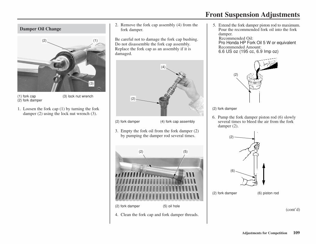
Front Suspension Adjustments
Adjustments for Competition 109
(1) fork cap (3) lock nut wrench (2) fork damper
1. Loosen the fork cap (1) by turning the forkdamper (2) using the lock nut wrench (3).
(2) fork damper (4) fork cap assembly
3. Empty the fork oil from the fork damper (2)by pumping the damper rod several times.
(2) fork damper (5) oil hole
4. Clean the fork cap and fork damper threads.
(2) fork damper
6. Pump the fork damper piston rod (6) slowlyseveral times to bleed the air from the forkdamper (2).
(2) fork damper (6) piston rod
(2)
(3)
(1)
(4)
(2)
(5)(2)
(2)
(2)
(6)
5. Extend the fork damper piston rod to maximum.Pour the recommended fork oil into the forkdamper.Recommended Oil:Pro Honda HP Fork Oil 5 W or equivalentRecommended Amount:6.6 US oz (195 cc, 6.9 Imp oz)
2. Remove the fork cap assembly (4) from thefork damper.
Be careful not to damage the fork cap bushing. Do not disassemble the fork cap assembly. Replace the fork cap as an assembly if it isdamaged.
Damper Oil Change
(cont’d)
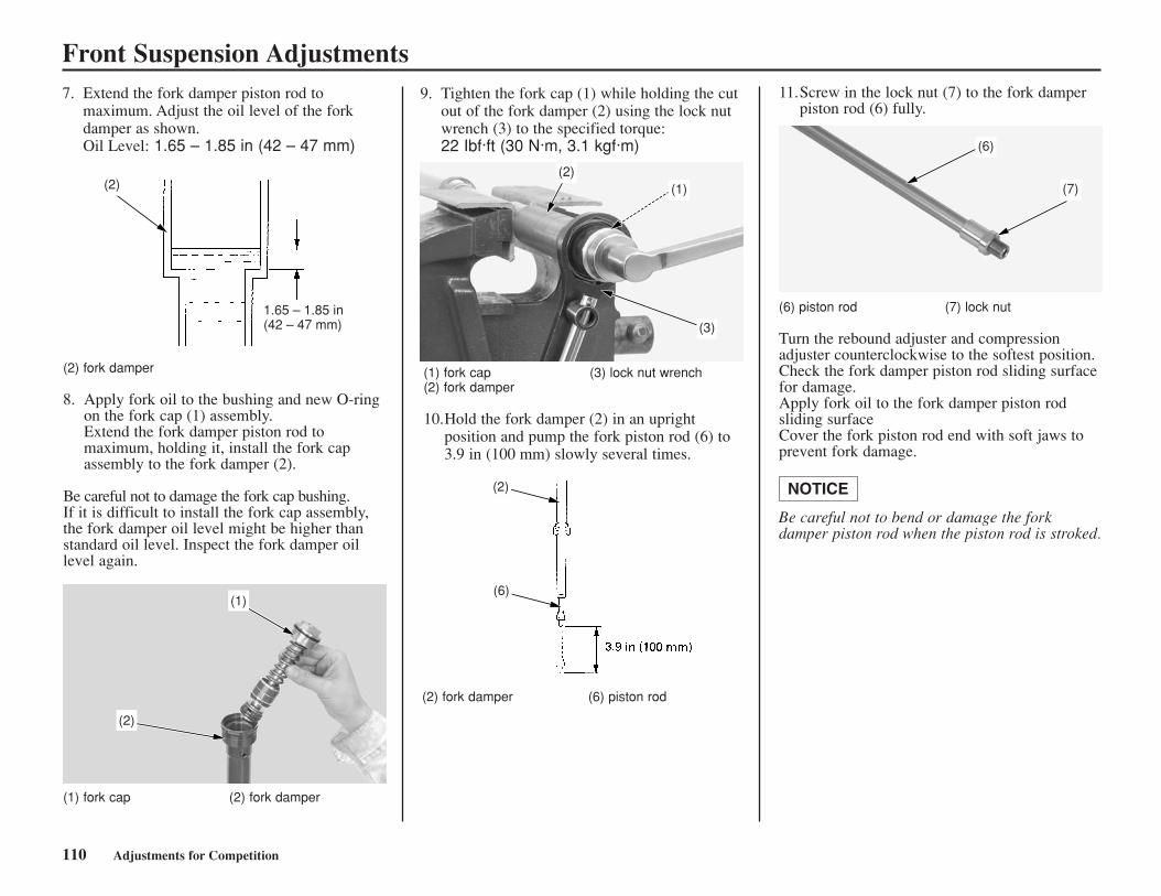
Front Suspension Adjustments
110 Adjustments for Competition
(2) fork damper (6) piston rod
(2)
(6)
(6) piston rod (7) lock nut
Turn the rebound adjuster and compressionadjuster counterclockwise to the softest position. Check the fork damper piston rod sliding surfacefor damage. Apply fork oil to the fork damper piston rodsliding surface Cover the fork piston rod end with soft jaws toprevent fork damage.
Be careful not to bend or damage the forkdamper piston rod when the piston rod is stroked.
NOTICE
(6)
(7)
11.Screw in the lock nut (7) to the fork damperpiston rod (6) fully.
(1) fork cap (3) lock nut wrench(2) fork damper
10.Hold the fork damper (2) in an uprightposition and pump the fork piston rod (6) to3.9 in (100 mm) slowly several times.
(2)
(3)
(1)
9. Tighten the fork cap (1) while holding the cutout of the fork damper (2) using the lock nutwrench (3) to the specified torque: 22 Ibf·ft (30 N·m, 3.1 kgf·m)
(2) fork damper
8. Apply fork oil to the bushing and new O-ringon the fork cap (1) assembly. Extend the fork damper piston rod tomaximum, holding it, install the fork capassembly to the fork damper (2).
Be careful not to damage the fork cap bushing.If it is difficult to install the fork cap assembly,the fork damper oil level might be higher thanstandard oil level. Inspect the fork damper oillevel again.
(1) fork cap (2) fork damper
1.65 – 1.85 in(42 – 47 mm)
(2)
(2)
(1)
7. Extend the fork damper piston rod tomaximum. Adjust the oil level of the forkdamper as shown.Oil Level: 1.65 – 1.85 in (42 – 47 mm)
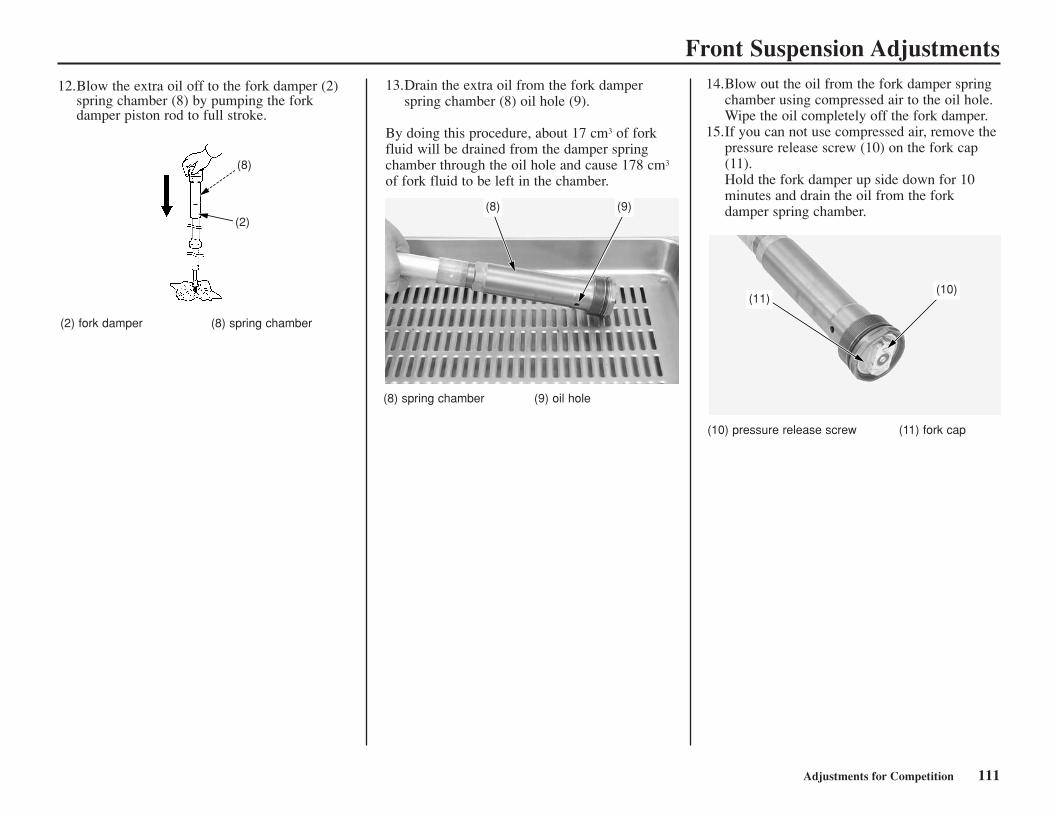
Front Suspension Adjustments
Adjustments for Competition 111
(2) fork damper (8) spring chamber
(10) pressure release screw (11) fork cap
(8) spring chamber (9) oil hole
(8)
(2)(8) (9)
(10)(11)
13.Drain the extra oil from the fork damperspring chamber (8) oil hole (9).
By doing this procedure, about 17 cm3 of forkfluid will be drained from the damper springchamber through the oil hole and cause 178 cm3
of fork fluid to be left in the chamber.
12.Blow the extra oil off to the fork damper (2)spring chamber (8) by pumping the forkdamper piston rod to full stroke.
14.Blow out the oil from the fork damper springchamber using compressed air to the oil hole. Wipe the oil completely off the fork damper.
15.If you can not use compressed air, remove thepressure release screw (10) on the fork cap(11). Hold the fork damper up side down for 10minutes and drain the oil from the forkdamper spring chamber.
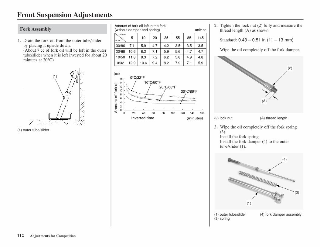
Front Suspension Adjustments
112 Adjustments for Competition
Fork Assembly
1. Drain the fork oil from the outer tube/sliderby placing it upside down.(About 7 cc of fork oil will be left in the outertube/slider when it is left inverted for about 20minutes at 20°C)
(1) outer tube/slider
2. Tighten the lock nut (2) fully and measure thethread length (A) as shown.
Standard: 0.43 – 0.51 in (11 – 13 mm)
Wipe the oil completely off the fork damper.
(2) lock nut (A) thread length
3. Wipe the oil completely off the fork spring(3).Install the fork spring.Install the fork damper (4) to the outertube/slider (1).
(1) outer tube/slider (4) fork damper assembly(3) spring
(1)
Amount of fork oil left in the fork(without damper and spring) unit: cc
minute
°C/°F
30/86
20/68
10/50
0/32
5
7.1
10.6
11.8
12.9
10
5.9
8.2
8.3
10.6
20
4.7
7.1
7.2
9.4
35
4.2
5.9
6.2
8.2
55
3.5
5.6
5.8
7.9
85
3.5
4.7
4.9
7.1
145
3.5
4.7
4.8
5.9(2)
(A)
(4)
(3)
(1)
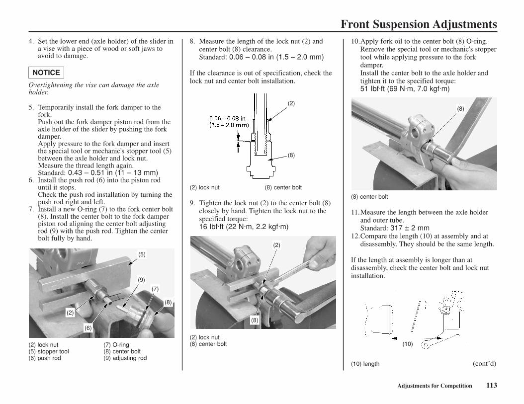
Adjustments for Competition 113
Front Suspension Adjustments4. Set the lower end (axle holder) of the slider in
a vise with a piece of wood or soft jaws toavoid to damage.
Overtightening the vise can damage the axleholder.
5. Temporarily install the fork damper to thefork. Push out the fork damper piston rod from theaxle holder of the slider by pushing the forkdamper.Apply pressure to the fork damper and insertthe special tool or mechanic's stopper tool (5)between the axle holder and lock nut. Measure the thread length again.Standard: 0.43 – 0.51 in (11 – 13 mm)
6. Install the push rod (6) into the piston roduntil it stops. Check the push rod installation by turning thepush rod right and left.
7. Install a new O-ring (7) to the fork center bolt(8). Install the center bolt to the fork damperpiston rod aligning the center bolt adjustingrod (9) with the push rod. Tighten the centerbolt fully by hand.
NOTICE
(2) lock nut (7) O-ring(5) stopper tool (8) center bolt(6) push rod (9) adjusting rod
8. Measure the length of the lock nut (2) andcenter bolt (8) clearance. Standard: 0.06 – 0.08 in (1.5 – 2.0 mm)
If the clearance is out of specification, check thelock nut and center bolt installation.
(2) lock nut (8) center bolt
9. Tighten the lock nut (2) to the center bolt (8)closely by hand. Tighten the lock nut to thespecified torque: 16 Ibf·ft (22 N·m, 2.2 kgf·m)
(2) lock nut(8) center bolt
10.Apply fork oil to the center bolt (8) O-ring.Remove the special tool or mechanic's stoppertool while applying pressure to the forkdamper. Install the center bolt to the axle holder andtighten it to the specified torque: 51 Ibf·ft (69 N·m, 7.0 kgf·m)
(8) center bolt
11.Measure the length between the axle holderand outer tube. Standard: 317 ± 2 mm
12.Compare the length (10) at assembly and atdisassembly. They should be the same length.
If the length at assembly is longer than atdisassembly, check the center bolt and lock nutinstallation.
(10) length (cont’d)
(8)
(7)
(9)
(5)
(2)
(6)
(2)
(8)
(8)
(2)
(8)
(10)
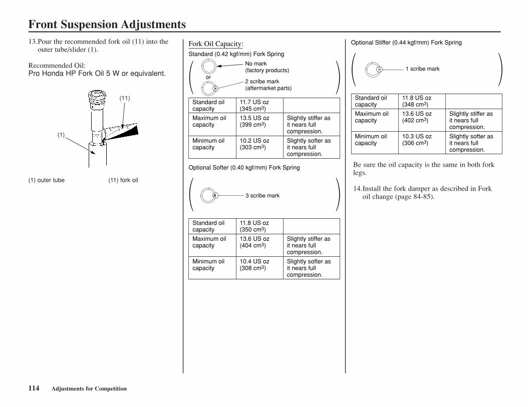
114 Adjustments for Competition
Front Suspension Adjustments13.Pour the recommended fork oil (11) into the
outer tube/slider (1).
Recommended Oil: Pro Honda HP Fork Oil 5 W or equivalent.
(1) outer tube (11) fork oil
(1)
(11)
( )
Fork Oil Capacity: Standard (0.42 kgf/mm) Fork Spring
Standard oilcapacity
11.7 US oz(345 cm3)
Maximum oilcapacity
13.5 US oz(399 cm3)
Slightly stiffer asit nears fullcompression.
Slightly softer asit nears fullcompression.
Minimum oilcapacity
10.2 US oz(303 cm3)
( )
Optional Softer (0.40 kgf/mm) Fork Spring
Standard oilcapacity
11.8 US oz(350 cm3)
Maximum oilcapacity
13.6 US oz(404 cm3)
Slightly stiffer asit nears fullcompression.
Slightly softer asit nears fullcompression.
Minimum oilcapacity
10.4 US oz(308 cm3)
No mark(factory products)
3 scribe mark
2 scribe mark(aftermarket parts)
or ( )Optional Stiffer (0.44 kgf/mm) Fork Spring
Standard oilcapacity
11.8 US oz(348 cm3)
Maximum oilcapacity
13.6 US oz(402 cm3)
Slightly stiffer asit nears fullcompression.
Slightly softer asit nears fullcompression.
Minimum oilcapacity
10.3 US oz(306 cm3)
1 scribe mark
Be sure the oil capacity is the same in both forklegs.
14.Install the fork damper as described in Forkoil change (page 84-85).
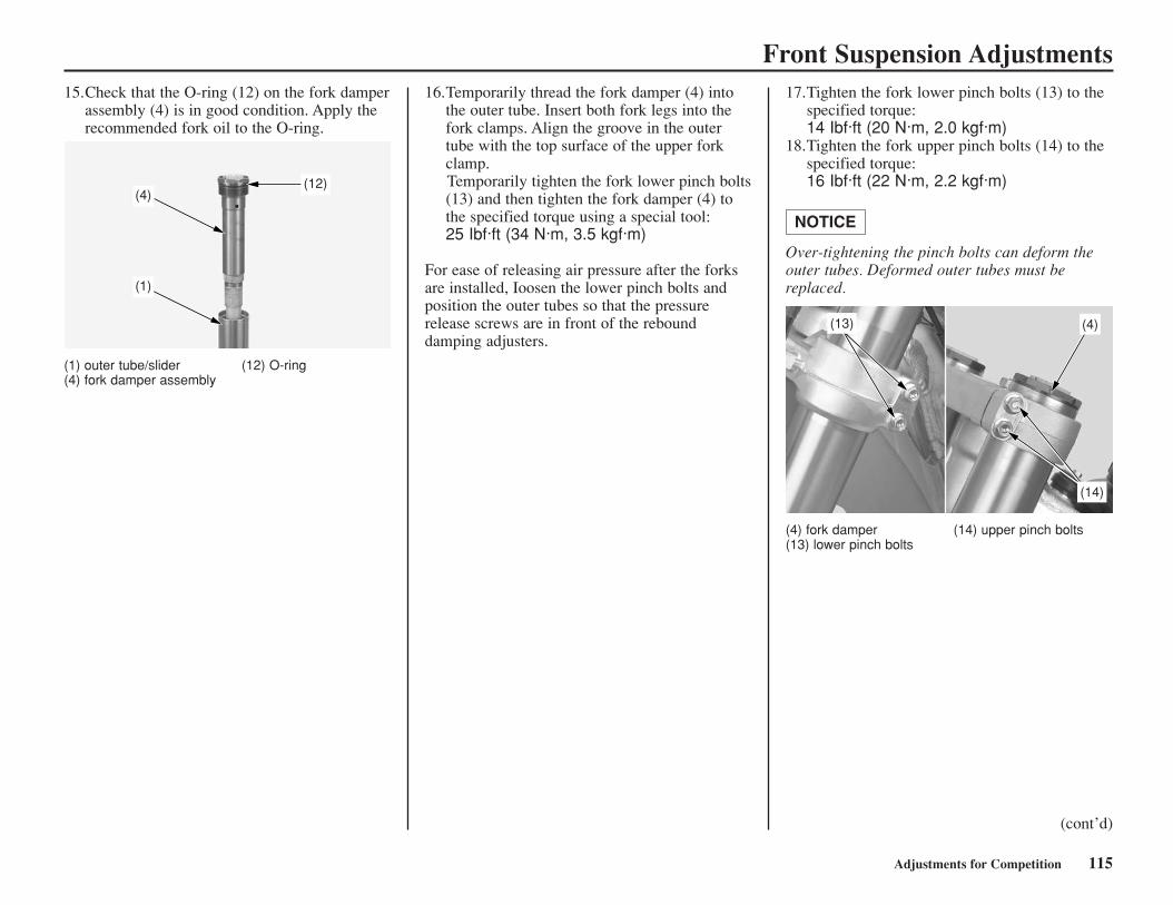
Adjustments for Competition 115
Front Suspension Adjustments15.Check that the O-ring (12) on the fork damper
assembly (4) is in good condition. Apply therecommended fork oil to the O-ring.
(1) outer tube/slider (12) O-ring (4) fork damper assembly
16.Temporarily thread the fork damper (4) intothe outer tube. Insert both fork legs into thefork clamps. Align the groove in the outertube with the top surface of the upper forkclamp. Temporarily tighten the fork lower pinch bolts(13) and then tighten the fork damper (4) tothe specified torque using a special tool: 25 Ibf·ft (34 N·m, 3.5 kgf·m)
For ease of releasing air pressure after the forksare installed, Ioosen the lower pinch bolts andposition the outer tubes so that the pressurerelease screws are in front of the rebounddamping adjusters.
17.Tighten the fork lower pinch bolts (13) to thespecified torque:14 Ibf·ft (20 N·m, 2.0 kgf·m)
18.Tighten the fork upper pinch bolts (14) to thespecified torque:16 Ibf·ft (22 N·m, 2.2 kgf·m)
Over-tightening the pinch bolts can deform theouter tubes. Deformed outer tubes must bereplaced.
NOTICE
(4) fork damper (14) upper pinch bolts(13) lower pinch bolts
(12)(4)
(1)
(13) (4)
(14)
(cont’d)
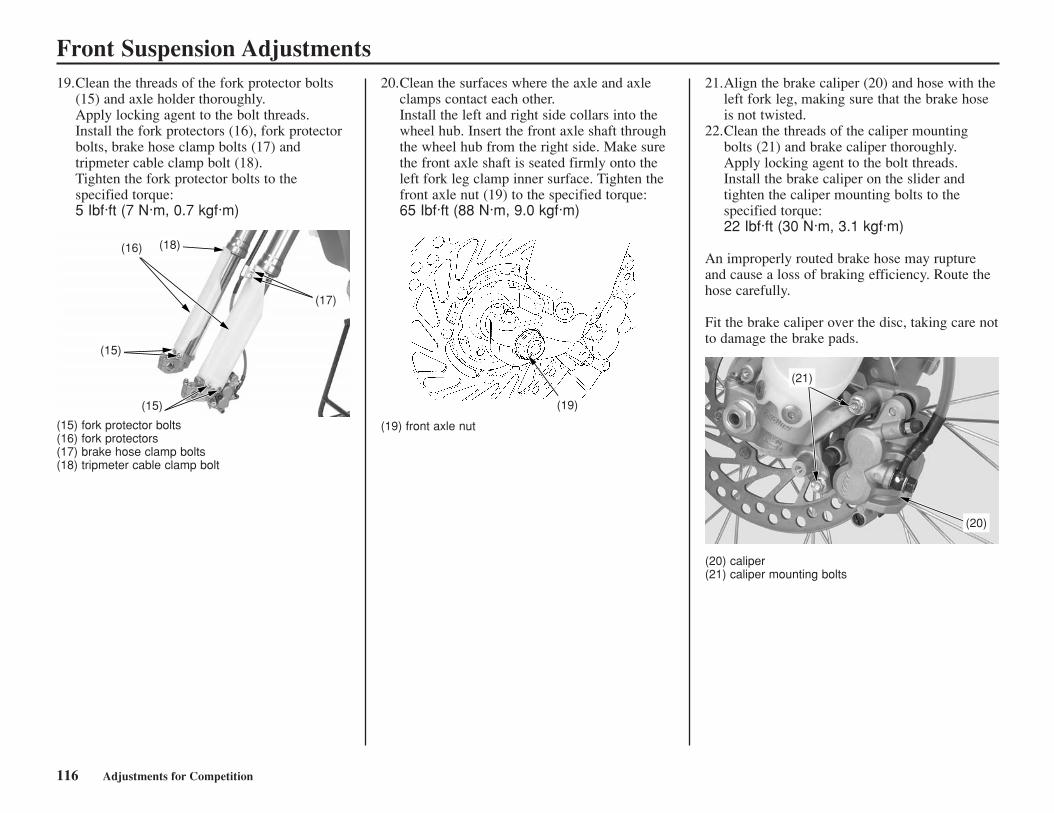
116 Adjustments for Competition
Front Suspension Adjustments19.Clean the threads of the fork protector bolts
(15) and axle holder thoroughly. Apply locking agent to the bolt threads. Install the fork protectors (16), fork protectorbolts, brake hose clamp bolts (17) andtripmeter cable clamp bolt (18).Tighten the fork protector bolts to thespecified torque:5 Ibf·ft (7 N·m, 0.7 kgf·m)
20.Clean the surfaces where the axle and axleclamps contact each other. Install the left and right side collars into thewheel hub. Insert the front axle shaft throughthe wheel hub from the right side. Make surethe front axle shaft is seated firmly onto theleft fork leg clamp inner surface. Tighten thefront axle nut (19) to the specified torque: 65 Ibf·ft (88 N·m, 9.0 kgf·m)
(19) front axle nut
21.Align the brake caliper (20) and hose with theleft fork leg, making sure that the brake hoseis not twisted.
22.Clean the threads of the caliper mountingbolts (21) and brake caliper thoroughly.Apply locking agent to the bolt threads.Install the brake caliper on the slider andtighten the caliper mounting bolts to thespecified torque:22 Ibf·ft (30 N·m, 3.1 kgf·m)
An improperly routed brake hose may ruptureand cause a loss of braking efficiency. Route thehose carefully.
Fit the brake caliper over the disc, taking care notto damage the brake pads.
(20) caliper (21) caliper mounting bolts
(18)(16)
(15)
(15)
(17)
(19)
(21)
(20)
(15) fork protector bolts(16) fork protectors(17) brake hose clamp bolts(18) tripmeter cable clamp bolt
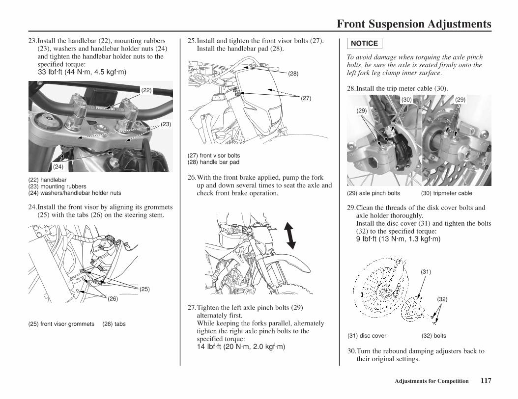
Adjustments for Competition 117
Front Suspension Adjustments23.Install the handlebar (22), mounting rubbers
(23), washers and handlebar holder nuts (24)and tighten the handlebar holder nuts to thespecified torque:33 Ibf·ft (44 N·m, 4.5 kgf·m)
(22) handlebar(23) mounting rubbers(24) washers/handlebar holder nuts
24.Install the front visor by aligning its grommets(25) with the tabs (26) on the steering stem.
(25) front visor grommets (26) tabs
25.Install and tighten the front visor bolts (27).Install the handlebar pad (28).
(27) front visor bolts(28) handle bar pad
26.With the front brake applied, pump the forkup and down several times to seat the axle andcheck front brake operation.
27.Tighten the left axle pinch bolts (29)alternately first. While keeping the forks parallel, alternatelytighten the right axle pinch bolts to thespecified torque:14 Ibf·ft (20 N·m, 2.0 kgf·m)
(29) axle pinch bolts (30) tripmeter cable
29.Clean the threads of the disk cover bolts andaxle holder thoroughly. Install the disc cover (31) and tighten the bolts(32) to the specified torque:9 Ibf·ft (13 N·m, 1.3 kgf·m)
(31) disc cover (32) bolts
30.Turn the rebound damping adjusters back totheir original settings.
(24)
(23)
(22)
(26)
(25)
(28)
(27)
(29)
(30) (29)
(31)
(32)
To avoid damage when torquing the axle pinchbolts, be sure the axle is seated firmly onto theleft fork leg clamp inner surface.
28.Install the trip meter cable (30).
NOTICE
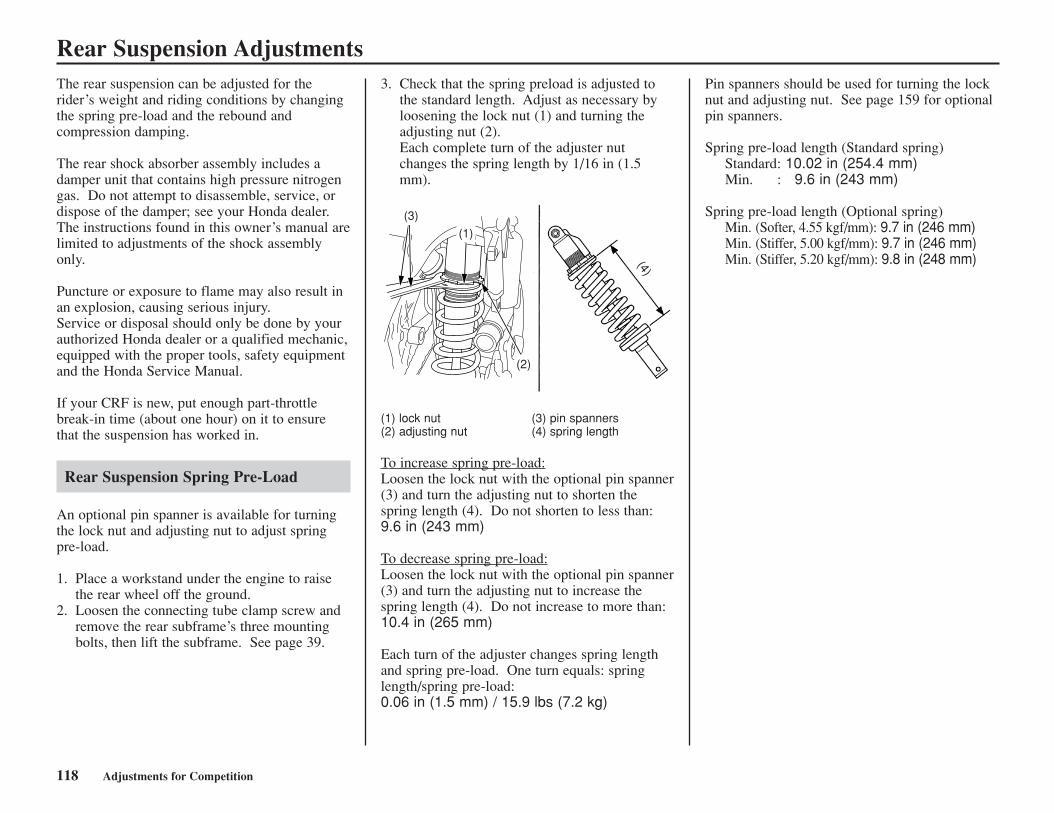
118 Adjustments for Competition
Rear Suspension AdjustmentsPin spanners should be used for turning the locknut and adjusting nut. See page 159 for optionalpin spanners.
Spring pre-load length (Standard spring)Standard: 10.02 in (254.4 mm)Min. : 9.6 in (243 mm)
Spring pre-load length (Optional spring)Min. (Softer, 4.55 kgf/mm): 9.7 in (246 mm)Min. (Stiffer, 5.00 kgf/mm): 9.7 in (246 mm)Min. (Stiffer, 5.20 kgf/mm): 9.8 in (248 mm)
The rear suspension can be adjusted for therider’s weight and riding conditions by changingthe spring pre-load and the rebound andcompression damping.
The rear shock absorber assembly includes adamper unit that contains high pressure nitrogengas. Do not attempt to disassemble, service, ordispose of the damper; see your Honda dealer.The instructions found in this owner’s manual arelimited to adjustments of the shock assemblyonly.
Puncture or exposure to flame may also result inan explosion, causing serious injury.Service or disposal should only be done by yourauthorized Honda dealer or a qualified mechanic,equipped with the proper tools, safety equipmentand the Honda Service Manual.
If your CRF is new, put enough part-throttlebreak-in time (about one hour) on it to ensurethat the suspension has worked in.
Rear Suspension Spring Pre-Load
An optional pin spanner is available for turningthe lock nut and adjusting nut to adjust springpre-load.
1. Place a workstand under the engine to raisethe rear wheel off the ground.
2. Loosen the connecting tube clamp screw andremove the rear subframe’s three mountingbolts, then lift the subframe. See page 39.
3. Check that the spring preload is adjusted tothe standard length. Adjust as necessary byloosening the lock nut (1) and turning theadjusting nut (2).Each complete turn of the adjuster nutchanges the spring length by 1/16 in (1.5mm).
(1) lock nut (3) pin spanners(2) adjusting nut (4) spring length
To increase spring pre-load:Loosen the lock nut with the optional pin spanner(3) and turn the adjusting nut to shorten thespring length (4). Do not shorten to less than:9.6 in (243 mm)
To decrease spring pre-load:Loosen the lock nut with the optional pin spanner(3) and turn the adjusting nut to increase thespring length (4). Do not increase to more than:10.4 in (265 mm)
Each turn of the adjuster changes spring lengthand spring pre-load. One turn equals: springlength/spring pre-load:0.06 in (1.5 mm) / 15.9 lbs (7.2 kg)
(3)
(1)
(2)
(4)
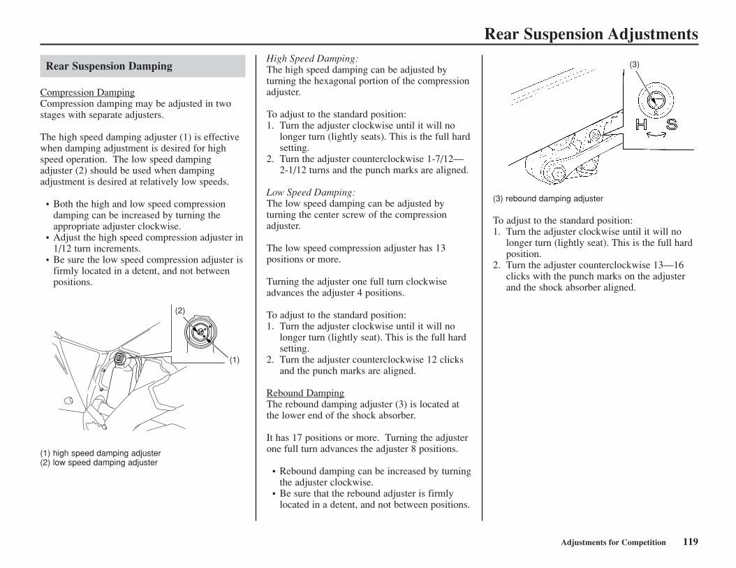
Adjustments for Competition 119
Rear Suspension Adjustments
(3) rebound damping adjuster
To adjust to the standard position:1. Turn the adjuster clockwise until it will no
longer turn (lightly seat). This is the full hardposition.
2. Turn the adjuster counterclockwise 13—16clicks with the punch marks on the adjusterand the shock absorber aligned.
Rear Suspension Damping
Compression DampingCompression damping may be adjusted in twostages with separate adjusters.
The high speed damping adjuster (1) is effectivewhen damping adjustment is desired for highspeed operation. The low speed dampingadjuster (2) should be used when dampingadjustment is desired at relatively low speeds.
• Both the high and low speed compressiondamping can be increased by turning theappropriate adjuster clockwise.
• Adjust the high speed compression adjuster in1/12 turn increments.
• Be sure the low speed compression adjuster isfirmly located in a detent, and not betweenpositions.
(1) high speed damping adjuster(2) low speed damping adjuster
High Speed Damping: The high speed damping can be adjusted byturning the hexagonal portion of the compressionadjuster.
To adjust to the standard position:1. Turn the adjuster clockwise until it will no
longer turn (lightly seats). This is the full hardsetting.
2. Turn the adjuster counterclockwise 1-7/12—2-1/12 turns and the punch marks are aligned.
Low Speed Damping:The low speed damping can be adjusted byturning the center screw of the compressionadjuster.
The low speed compression adjuster has 13positions or more.
Turning the adjuster one full turn clockwiseadvances the adjuster 4 positions.
To adjust to the standard position:1. Turn the adjuster clockwise until it will no
longer turn (lightly seat). This is the full hardsetting.
2. Turn the adjuster counterclockwise 12 clicksand the punch marks are aligned.
Rebound DampingThe rebound damping adjuster (3) is located atthe lower end of the shock absorber.
It has 17 positions or more. Turning the adjusterone full turn advances the adjuster 8 positions.
• Rebound damping can be increased by turningthe adjuster clockwise.
• Be sure that the rebound adjuster is firmlylocated in a detent, and not between positions.
(1)
(2)
1(3)
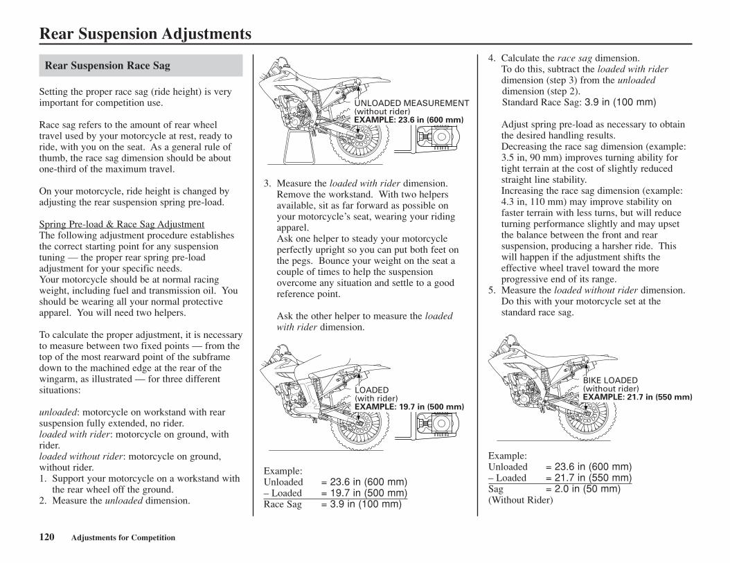
120 Adjustments for Competition
Rear Suspension Adjustments4. Calculate the race sag dimension.
To do this, subtract the loaded with riderdimension (step 3) from the unloadeddimension (step 2).Standard Race Sag: 3.9 in (100 mm)
Adjust spring pre-load as necessary to obtainthe desired handling results.Decreasing the race sag dimension (example:3.5 in, 90 mm) improves turning ability fortight terrain at the cost of slightly reducedstraight line stability.Increasing the race sag dimension (example:4.3 in, 110 mm) may improve stability onfaster terrain with less turns, but will reduceturning performance slightly and may upsetthe balance between the front and rearsuspension, producing a harsher ride. Thiswill happen if the adjustment shifts theeffective wheel travel toward the moreprogressive end of its range.
5. Measure the loaded without rider dimension.Do this with your motorcycle set at thestandard race sag.
Rear Suspension Race Sag
Setting the proper race sag (ride height) is veryimportant for competition use.
Race sag refers to the amount of rear wheeltravel used by your motorcycle at rest, ready toride, with you on the seat. As a general rule ofthumb, the race sag dimension should be aboutone-third of the maximum travel.
On your motorcycle, ride height is changed byadjusting the rear suspension spring pre-load.
Spring Pre-load & Race Sag AdjustmentThe following adjustment procedure establishesthe correct starting point for any suspensiontuning — the proper rear spring pre-loadadjustment for your specific needs.Your motorcycle should be at normal racingweight, including fuel and transmission oil. Youshould be wearing all your normal protectiveapparel. You will need two helpers.
To calculate the proper adjustment, it is necessaryto measure between two fixed points — from thetop of the most rearward point of the subframedown to the machined edge at the rear of thewingarm, as illustrated — for three differentsituations:
unloaded: motorcycle on workstand with rearsuspension fully extended, no rider.loaded with rider: motorcycle on ground, withrider.loaded without rider: motorcycle on ground,without rider.1. Support your motorcycle on a workstand with
the rear wheel off the ground.2. Measure the unloaded dimension.
3. Measure the loaded with rider dimension.Remove the workstand. With two helpersavailable, sit as far forward as possible onyour motorcycle’s seat, wearing your ridingapparel.Ask one helper to steady your motorcycleperfectly upright so you can put both feet onthe pegs. Bounce your weight on the seat acouple of times to help the suspensionovercome any situation and settle to a goodreference point.
Ask the other helper to measure the loadedwith rider dimension.
Example: Unloaded = 23.6 in (600 mm) – Loaded = 19.7 in (500 mm)Race Sag = 3.9 in (100 mm)
UNLOADED MEASUREMENT(without rider)EXAMPLE: 23.6 in (600 mm)
LOADED(with rider)EXAMPLE: 19.7 in (500 mm)
BIKE LOADED(without rider)EXAMPLE: 21.7 in (550 mm)
Example:Unloaded = 23.6 in (600 mm) – Loaded = 21.7 in (550 mm)Sag = 2.0 in (50 mm)(Without Rider)
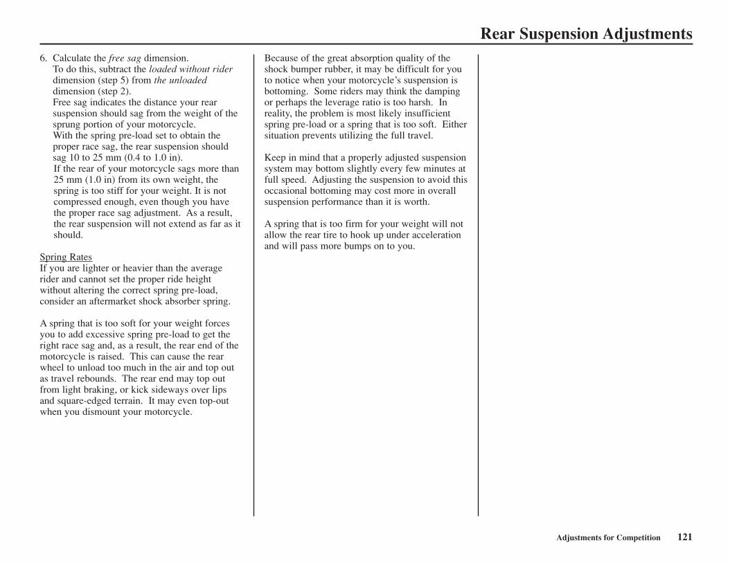
Adjustments for Competition 121
Rear Suspension AdjustmentsBecause of the great absorption quality of theshock bumper rubber, it may be difficult for youto notice when your motorcycle’s suspension isbottoming. Some riders may think the dampingor perhaps the leverage ratio is too harsh. Inreality, the problem is most likely insufficientspring pre-load or a spring that is too soft. Eithersituation prevents utilizing the full travel.
Keep in mind that a properly adjusted suspensionsystem may bottom slightly every few minutes atfull speed. Adjusting the suspension to avoid thisoccasional bottoming may cost more in overallsuspension performance than it is worth.
A spring that is too firm for your weight will notallow the rear tire to hook up under accelerationand will pass more bumps on to you.
6. Calculate the free sag dimension.To do this, subtract the loaded without riderdimension (step 5) from the unloadeddimension (step 2).Free sag indicates the distance your rearsuspension should sag from the weight of thesprung portion of your motorcycle.With the spring pre-load set to obtain theproper race sag, the rear suspension shouldsag 10 to 25 mm (0.4 to 1.0 in).If the rear of your motorcycle sags more than25 mm (1.0 in) from its own weight, thespring is too stiff for your weight. It is notcompressed enough, even though you havethe proper race sag adjustment. As a result,the rear suspension will not extend as far as itshould.
Spring RatesIf you are lighter or heavier than the averagerider and cannot set the proper ride heightwithout altering the correct spring pre-load,consider an aftermarket shock absorber spring.
A spring that is too soft for your weight forcesyou to add excessive spring pre-load to get theright race sag and, as a result, the rear end of themotorcycle is raised. This can cause the rearwheel to unload too much in the air and top outas travel rebounds. The rear end may top outfrom light braking, or kick sideways over lipsand square-edged terrain. It may even top-outwhen you dismount your motorcycle.
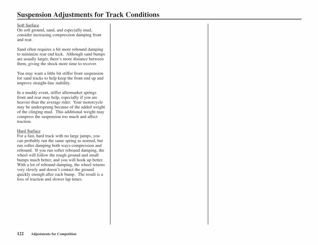
122 Adjustments for Competition
Suspension Adjustments for Track ConditionsSoft SurfaceOn soft ground, sand, and especially mud,consider increasing compression damping frontand rear.
Sand often requires a bit more rebound dampingto minimize rear end kick. Although sand bumpsare usually larger, there’s more distance betweenthem, giving the shock more time to recover.
You may want a little bit stiffer front suspensionfor sand tracks to help keep the front end up andimprove straight-line stability.
In a muddy event, stiffer aftermarket springsfront and rear may help, especially if you areheavier than the average rider. Your motorcyclemay be undersprung because of the added weightof the clinging mud. This additional weight maycompress the suspension too much and affecttraction.
Hard SurfaceFor a fast, hard track with no large jumps, youcan probably run the same spring as normal, butrun softer damping both ways-compression andrebound. If you run softer rebound damping, thewheel will follow the rough ground and smallbumps much better, and you will hook up better.With a lot of rebound damping, the wheel returnsvery slowly and doesn’t contact the groundquickly enough after each bump. The result is aloss of traction and slower lap times.
Adjustments for Competition 123
Suspension Adjustment GuidelinesFollow the procedures described below to accurately adjust your CRF, using the methods described on pages 104 - 119. Remember to make all adjustments inone-click increments. Test ride after each adjustment.
Front Suspension AdjustmentAdjustments for Type of Track
Adjustments for Too Soft/Stiff Damping
Hard-surfaced track
Sand track
Mud track
Begin with the standard setting. If the suspension is too stiff/soft, adjust according to the chart below.
Adjust to a stiffer position.Example: – Turn the compression damping adjuster to a stiffer position.
– Install the optional stiff spring. (Adjust compression damping to a softer position and rebound damping to a harder position atthis time.)
Adjust to a stiffer position because mud build-up increases your CRF’s weight.Example: – Turn the compression damping adjuster to a stiffer setting.
– Install the optional stiff spring.
Soft suspension
Symptom
Initial travel too soft:• Steering is too quick.• Front end darts while cornering or riding in a straight line.
Middle travel too soft:• Front end dives when cornering.
Final travel too soft:• Bottoms on landings.• Bottoms on large bumps, especially downhill bumps.
Entire travel too soft:• Front end shakes.• Fork bottoms over any type of terrain.
Action
– Test stiffer compression damping adjustments in one-click increments.– Test stiffer rebound damping in one-click increments.
If suspension isn’t stiff in initial travel:– Test stiffer compression damping adjustments in one-click increments.If initial travel becomes stiff because of the above adjustment:– Reduce the rebound damping in one-click increments.– Test softer compression damping adjustments in one-click increments.If that doesn’t solve the problem, install the optional stiff spring.
If initial and middle travel aren’t stiff:– Test stiffer compression damping adjustments in one-click increments.If initial and middle travel are stiff:– Install the optional stiff spring.If initial travel is stiff after installing the optional stiff spring:– Test soft compression damping adjustments in one-click increments.If initial travel is still soft after installing the optional stiff spring:– Test stiffer compression damping adjustments in one-click increments.If final travel is still soft after installing the optional stiff spring:– Increase the fork oil capacity in increments of 0.2 oz (5 cc).
– Install the optional stiff spring.– Test stiffer compression damping adjustments in one-click increments.– Increase rebound damping in one-click increments.
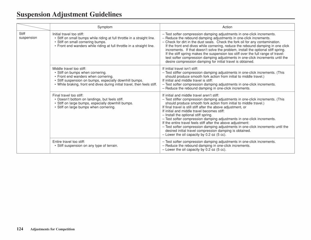
124 Adjustments for Competition
Suspension Adjustment Guidelines
Stiffsuspension
Symptom
Initial travel too stiff:• Stiff on small bumps while riding at full throttle in a straight line.• Stiff on small cornering bumps.• Front end wanders while riding at full throttle in a straight line.
Middle travel too stiff:• Stiff on bumps when cornering.• Front end wanders when cornering.• Stiff suspension on bumps, especially downhill bumps.• While braking, front end dives during initial travel, then feels stiff.
Final travel too stiff:• Doesn’t bottom on landings, but feels stiff.• Stiff on large bumps, especially downhill bumps.• Stiff on large bumps when cornering.
Entire travel too stiff:• Stiff suspension on any type of terrain.
Action
– Test softer compression damping adjustments in one-click increments.– Reduce the rebound damping adjustments in one-click increments.– Check for dirt in the dust seals. Check the fork oil for any contamination.
If the front end dives while cornering, reduce the rebound damping in one clickincrements. If that doesn’t solve the problem, install the optional stiff spring.If the stiff spring makes the suspension too stiff over the full range of travel:test softer compression damping adjustments in one-click increments until thedesire compression damping for initial travel is obtained.
If initial travel isn’t stiff:– Test stiffer compression damping adjustments in one-click increments. (This
should produce smooth fork action from initial to middle travel.)If initial and middle travel is stiff:– Test softer compression damping adjustments in one-click increments.– Reduce the rebound damping in one-click increments.
If initial and middle travel aren’t stiff:– Test stiffer compression damping adjustments in one-click increments. (This
should produce smooth fork action from initial to middle travel.)If final travel is still stiff after the above adjustment, orIf initial and middle travel becomes stiff:– Install the optional stiff spring.– Test softer compression damping adjustments in one-click increments.If the entire travel feels stiff after the above adjustment:– Test softer compression damping adjustments in one-click increments until the
desired initial travel compression damping is obtained.– Lower the oil capacity by 0.2 oz (5 cc).
– Test softer compression damping adjustments in one-click increments.– Reduce the rebound damping in one-click increments.– Lower the oil capacity by 0.2 oz (5 cc).
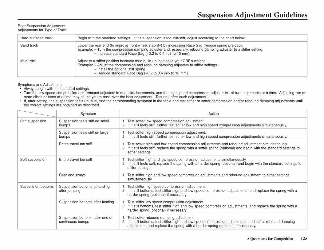
Adjustments for Competition 125
Suspension Adjustment GuidelinesRear Suspension AdjustmentAdjustments for Type of Track
Symptoms and Adjustment• Always begin with the standard settings.• Turn the low speed compression and rebound adjusters in one-click increments, and the high speed compression adjuster in 1/6 turn increments at a time. Adjusting two or
more clicks or turns at a time may cause you to pass over the best adjustment. Test ride after each adjustment.• If, after setting, the suspension feels unusual, find the corresponding symptom in the table and test stiffer or softer compression and/or rebound damping adjustments until
the correct settings are obtained as described.
Hard-surfaced track
Sand track
Mud track
Begin with the standard settings. If the suspension is too stiff/soft, adjust according to the chart below.
Lower the rear end (to improve front wheel stability) by increasing Race Sag (reduce spring preload).Example: – Turn the compression damping adjuster and, especially, rebound damping adjuster to a stiffer setting.
– Increase standard Race Sag (+0.2 to 0.4 in/5 to 10 mm).
Adjust to a stiffer position because mud build-up increases your CRF’s weight.Example: – Adjust the compression and rebound damping adjusters to stiffer settings.
– Install the optional stiff spring.– Reduce standard Race Sag (–0.2 to 0.4 in/5 to 10 mm).
Stiff suspension
Soft suspension
Suspension bottoms
Symptom
Suspension feels stiff on smallbumps
Suspension feels stiff on largebumps
Entire travel too stiff
Entire travel too soft
Rear end sways
Suspension bottoms at landingafter jumping
Suspension bottoms after landing
Suspension bottoms after end ofcontinuous bumps
Action
1. Test softer low speed compression adjustment.2. If it still feels stiff, further test softer low and high speed compression adjustments simultaneously.
1. Test softer high speed compression adjustment.2. If it still feels stiff, further test softer low and high speed compression adjustments simultaneously.
1. Test softer high and low speed compression adjustments and rebound adjustment simultaneously.2. If it still feels stiff, replace the spring with a softer spring (optional) and begin with the standard settings to
softer settings.
1. Test stiffer high and low speed compression adjustments simultaneously.2. If it still feels soft, replace the spring with a harder spring (optional) and begin with the standard settings to
stiffer setting.
1. Test stiffer high and low speed compression adjustments and rebound adjustment to stiffer settingssimultaneously.
1. Test stiffer high speed compression adjustment.2. If it still bottoms, test stiffer high and low speed compression adjustments, and replace the spring with a
harder spring (optional) if necessary.
1. Test stiffer low speed compression adjustment.2. If it still bottoms, test stiffer high and low speed compression adjustments, and replace the spring with a
harder spring (optional) if necessary.
1. Test softer rebound dumping adjustment.2. If it still bottoms, test stiffer high and low speed compression adjustments and softer rebound damping
adjustment, and replace the spring with a harder spring (optional) if necessary.
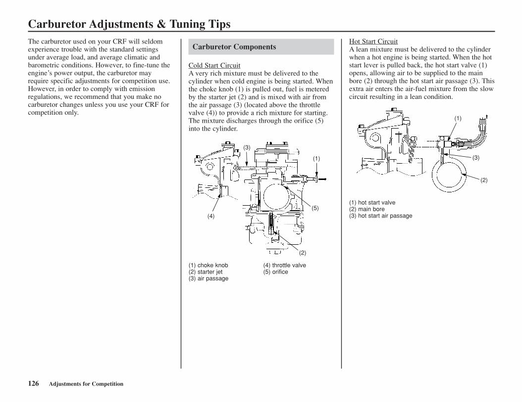
126 Adjustments for Competition
Carburetor Adjustments & Tuning TipsThe carburetor used on your CRF will seldomexperience trouble with the standard settingsunder average load, and average climatic andbarometric conditions. However, to fine-tune theengine’s power output, the carburetor mayrequire specific adjustments for competition use.However, in order to comply with emissionregulations, we recommend that you make nocarburetor changes unless you use your CRF forcompetition only.
Carburetor Components
Cold Start CircuitA very rich mixture must be delivered to thecylinder when cold engine is being started. Whenthe choke knob (1) is pulled out, fuel is meteredby the starter jet (2) and is mixed with air fromthe air passage (3) (located above the throttlevalve (4)) to provide a rich mixture for starting.The mixture discharges through the orifice (5)into the cylinder.
(1) choke knob (4) throttle valve(2) starter jet (5) orifice(3) air passage
Hot Start CircuitA lean mixture must be delivered to the cylinderwhen a hot engine is being started. When the hotstart lever is pulled back, the hot start valve (1)opens, allowing air to be supplied to the mainbore (2) through the hot start air passage (3). Thisextra air enters the air-fuel mixture from the slowcircuit resulting in a lean condition.
(1) hot start valve(2) main bore(3) hot start air passage
3
(1)
(5)
(2)
(4)
(3)
(2)
(1)
(3)
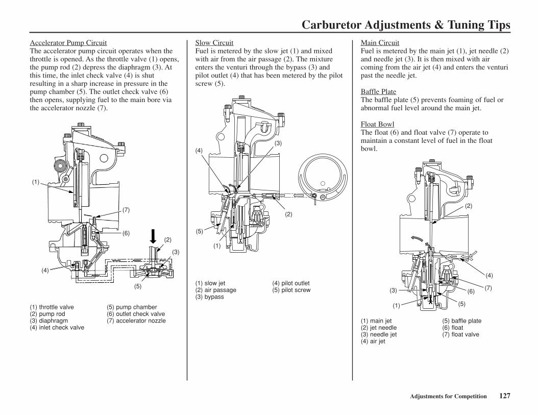
Carburetor Adjustments & Tuning Tips
Adjustments for Competition 127
Accelerator Pump CircuitThe accelerator pump circuit operates when thethrottle is opened. As the throttle valve (1) opens,the pump rod (2) depress the diaphragm (3). Atthis time, the inlet check valve (4) is shutresulting in a sharp increase in pressure in thepump chamber (5). The outlet check valve (6)then opens, supplying fuel to the main bore viathe accelerator nozzle (7).
(1) throttle valve (5) pump chamber(2) pump rod (6) outlet check valve(3) diaphragm (7) accelerator nozzle(4) inlet check valve
Slow CircuitFuel is metered by the slow jet (1) and mixedwith air from the air passage (2). The mixtureenters the venturi through the bypass (3) andpilot outlet (4) that has been metered by the pilotscrew (5).
(1) slow jet (4) pilot outlet(2) air passage (5) pilot screw(3) bypass
Main CircuitFuel is metered by the main jet (1), jet needle (2)and needle jet (3). It is then mixed with aircoming from the air jet (4) and enters the venturipast the needle jet.
Baffle PlateThe baffle plate (5) prevents foaming of fuel orabnormal fuel level around the main jet.
Float BowlThe float (6) and float valve (7) operate tomaintain a constant level of fuel in the floatbowl.
(1) main jet (5) baffle plate(2) jet needle (6) float(3) needle jet (7) float valve(4) air jet
(3)
2
(1)
(7)
(6)(2)
(5)
(4)
(3)
(2)
(1)
(5)
(4)
(2)
(4)
(7)(6)
(5)(1)
(3)
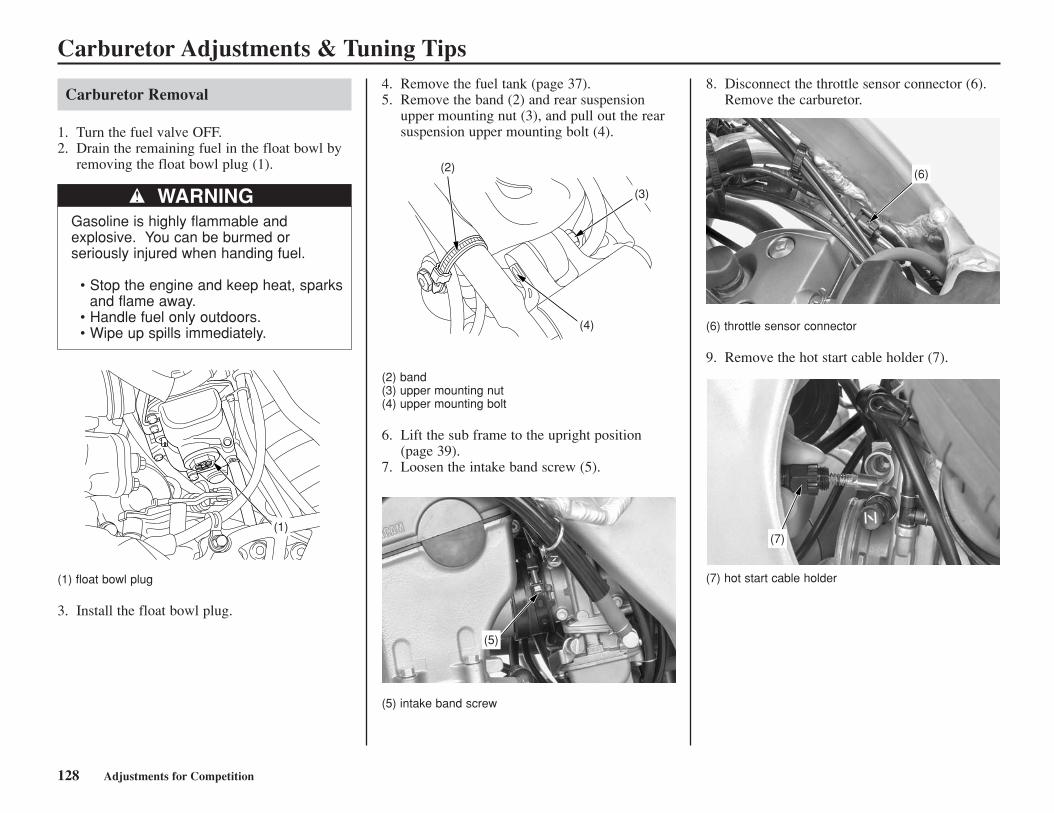
Carburetor Adjustments & Tuning Tips
Carburetor Removal
1. Turn the fuel valve OFF.2. Drain the remaining fuel in the float bowl by
removing the float bowl plug (1).
WARNINGGasoline is highly flammable andexplosive. You can be burmed orseriously injured when handing fuel.
• Stop the engine and keep heat, sparksand flame away.
• Handle fuel only outdoors.• Wipe up spills immediately.
(1) float bowl plug
3. Install the float bowl plug.
(1)
128 Adjustments for Competition
4. Remove the fuel tank (page 37).5. Remove the band (2) and rear suspension
upper mounting nut (3), and pull out the rearsuspension upper mounting bolt (4).
(2) band(3) upper mounting nut(4) upper mounting bolt
6. Lift the sub frame to the upright position(page 39).
7. Loosen the intake band screw (5).
(5) intake band screw
8. Disconnect the throttle sensor connector (6).Remove the carburetor.
(6) throttle sensor connector
9. Remove the hot start cable holder (7).
(7) hot start cable holder
(2)
(3)
(4)
(5)
(6)
(7)
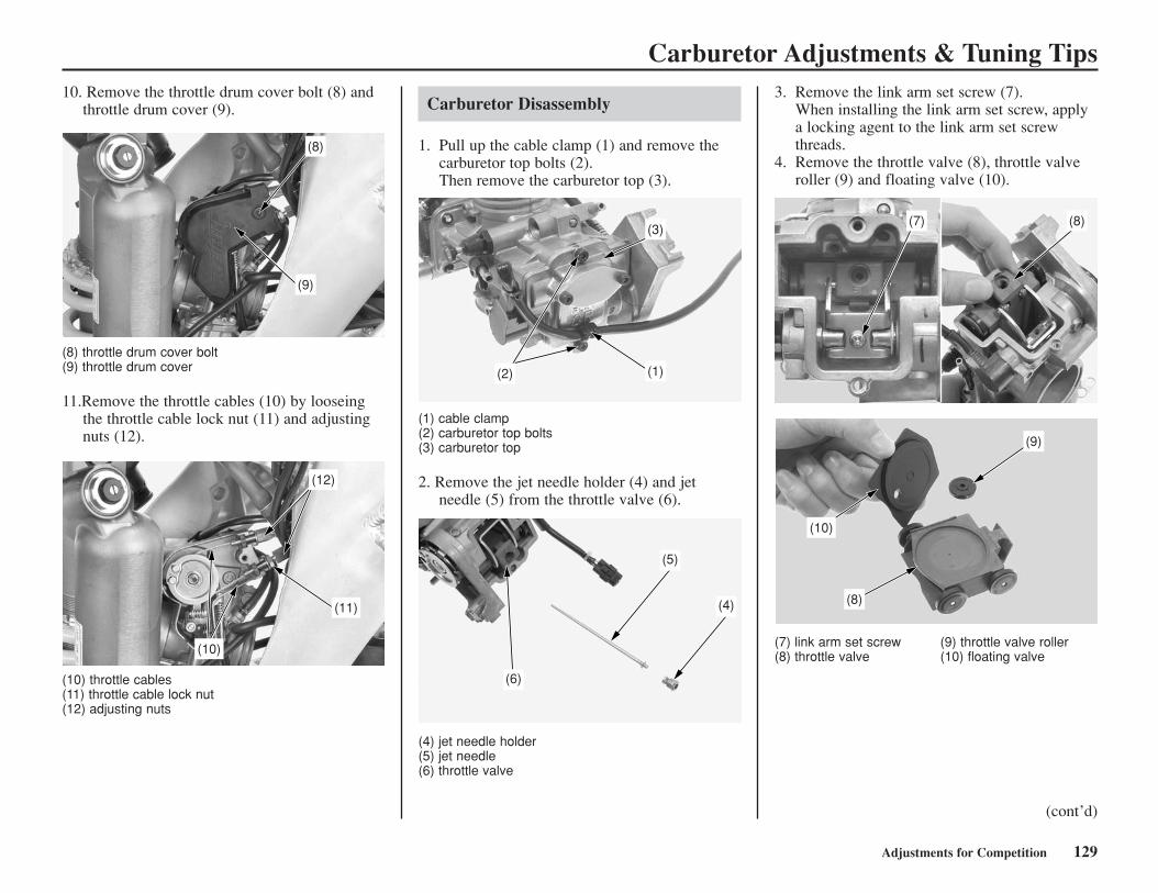
Carburetor Adjustments & Tuning Tips
Adjustments for Competition 129
Carburetor Disassembly
1. Pull up the cable clamp (1) and remove thecarburetor top bolts (2).Then remove the carburetor top (3).
(1) cable clamp(2) carburetor top bolts(3) carburetor top
2. Remove the jet needle holder (4) and jetneedle (5) from the throttle valve (6).
(4) jet needle holder(5) jet needle(6) throttle valve
3. Remove the link arm set screw (7).When installing the link arm set screw, applya locking agent to the link arm set screwthreads.
4. Remove the throttle valve (8), throttle valveroller (9) and floating valve (10).
(7) link arm set screw (9) throttle valve roller(8) throttle valve (10) floating valve
(2) (1)
(3)
(6)
(5)
(4)
(7) (8)
(9)
(10)
(8)
10. Remove the throttle drum cover bolt (8) andthrottle drum cover (9).
(8) throttle drum cover bolt(9) throttle drum cover
11.Remove the throttle cables (10) by looseingthe throttle cable lock nut (11) and adjustingnuts (12).
(10) throttle cables(11) throttle cable lock nut(12) adjusting nuts
(cont’d)
(8)
(9)
(10)
(12)
(11)
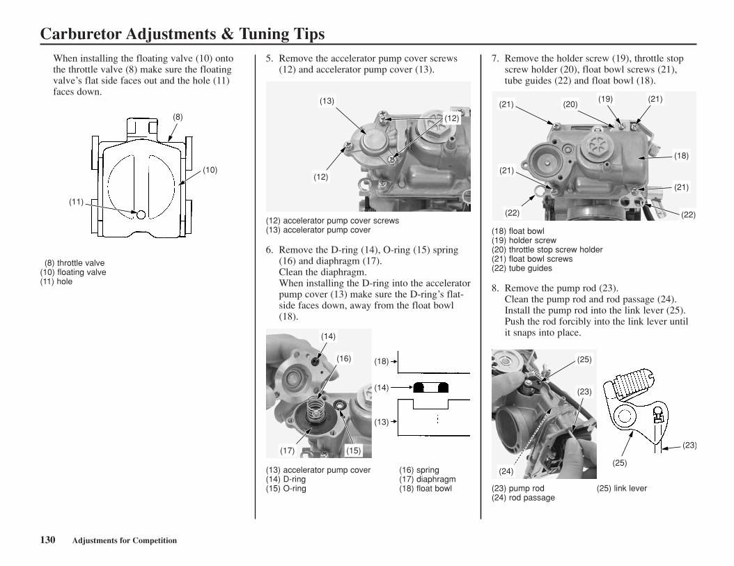
Carburetor Adjustments & Tuning TipsWhen installing the floating valve (10) ontothe throttle valve (8) make sure the floatingvalve’s flat side faces out and the hole (11)faces down.
(8) throttle valve(10) floating valve(11) hole
(11)
(8)
(10)
130 Adjustments for Competition
5. Remove the accelerator pump cover screws(12) and accelerator pump cover (13).
(12) accelerator pump cover screws(13) accelerator pump cover
6. Remove the D-ring (14), O-ring (15) spring(16) and diaphragm (17).Clean the diaphragm.When installing the D-ring into the acceleratorpump cover (13) make sure the D-ring’s flat-side faces down, away from the float bowl(18).
(13) accelerator pump cover (16) spring(14) D-ring (17) diaphragm(15) O-ring (18) float bowl
7. Remove the holder screw (19), throttle stopscrew holder (20), float bowl screws (21),tube guides (22) and float bowl (18).
(18) float bowl(19) holder screw(20) throttle stop screw holder(21) float bowl screws(22) tube guides
8. Remove the pump rod (23).Clean the pump rod and rod passage (24).Install the pump rod into the link lever (25).Push the rod forcibly into the link lever untilit snaps into place.
(23) pump rod (25) link lever(24) rod passage
(13)
(12)
(12)
(14)
(18)
(14)
(13)
(16)
(17) (15)
(22)
(21)
(21) (20)(19) (21)
(18)
(21)
(22)
(25)(24)
(25)
(23)
(23)
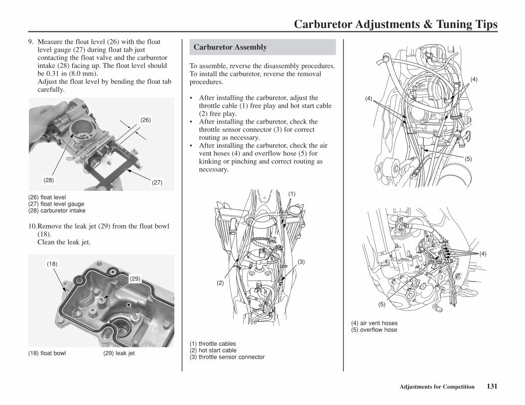
Carburetor Adjustments & Tuning Tips
(26) float level(27) float level gauge(28) carburetor intake
10.Remove the leak jet (29) from the float bowl(18).Clean the leak jet.
9. Measure the float level (26) with the floatlevel gauge (27) during float tab justcontacting the float valve and the carburetorintake (28) facing up. The float level shouldbe 0.31 in (8.0 mm).Adjust the float level by bending the float tabcarefully.
(18) float bowl (29) leak jet
(26)
(27)(28)
(18)
(29)
Adjustments for Competition 131
(1) throttle cables(2) hot start cable(3) throttle sensor connector
(4) air vent hoses(5) overflow hose
(2)
(1)
(3)
(4)
(5)
(4)
(5)
(4)
Carburetor Assembly
To assemble, reverse the disassembly procedures.To install the carburetor, reverse the removalprocedures.
• After installing the carburetor, adjust thethrottle cable (1) free play and hot start cable(2) free play.
• After installing the carburetor, check thethrottle sensor connector (3) for correctrouting as necessary.
• After installing the carburetor, check the airvent hoses (4) and overflow hose (5) forkinking or pinching and correct routing asnecessary.
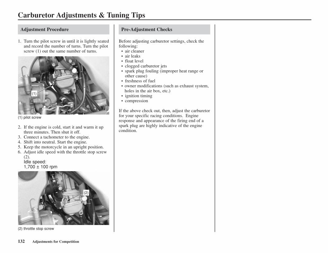
Carburetor Adjustments & Tuning Tips
Pre-Adjustment Checks
Before adjusting carburetor settings, check thefollowing:
• air cleaner• air leaks• float level• clogged carburetor jets• spark plug fouling (improper heat range or
other cause)• freshness of fuel• owner modifications (such as exhaust system,
holes in the air box, etc.)• ignition timing• compression
If the above check out, then, adjust the carburetorfor your specific racing conditions. Engineresponse and appearance of the firing end of aspark plug are highly indicative of the enginecondition.
132 Adjustments for Competition
Adjustment Procedure
1. Turn the pilot screw in until it is lightly seatedand record the number of turns. Turn the pilotscrew (1) out the same number of turns.
(1) pilot screw
2. If the engine is cold, start it and warm it upthree minutes. Then shut it off.
3. Connect a tachometer to the engine.4. Shift into neutral. Start the engine.5. Keep the motorcycle in an upright position.6. Adjust idle speed with the throttle stop screw
(2).Idle speed:1,700 ± 100 rpm
(2) throttle stop screw
(1)
(2)

Chassis Adjustments
Adjustments for Competition 133
The following suggestions may improve aspecific concern. Subtle changes in overallhandling may also be noted.
Rear End
If you have a problem with rear wheel traction,raise the rear end of your motorcycle byincreasing the rear spring pre-load. Instead ofrunning 3.9 in (100 mm) of sag, you can run 3.5in (90 mm) so the rear of the bike will sit a littlehigher. This should produce more tractionbecause of the change to the swingarm and thelocation of your motorcycle’s center of gravity.
If you have a problem with the steering headshaking when you use the front brake hard or ifyour motorcycle wants to turn too quickly, lowerthe rear of the motorcycle by reducing the rearspring pre-load. This will increase fork rake andtrail and should improve stability in a straightline. The effective suspension travel will betransferred toward the firmer end of wheel travel.
Keep the race sag adjustment (page 120) in the90 - 100 mm range.
Fork Height/Angle
Standard PositionThe position of the outer tubes in the clamps isnot adjustable. Align the top of the fork tube (1)with the top of the upper fork clamp (2).
(STANDARD POSITON)
Wheelbase
Adjusting your motorcycle’s wheelbase can offersubtle changes in overall handling. You mayadjust wheelbase by adding or removing links onthe drive chain. If you change the wheelbase, besure to re-check race sag and adjust, if necessary.
In the past, a general rule was lengthen thewheelbase to add straight line stability, shortenthe wheelbase to improve turning. However, wesuggest you do not lengthen the wheelbase ofyour motorcycle unless you are racing on a trackwith more fast sections than normal.
As a general recommendation, keep thewheelbase as short as possible. This positionsthe wheels closer together, improves turningresponse, increase weighting (traction) on therear wheel, and lightens weighting on the frontwheel.
With your motorcycle, you will probably findthat the standard setting or a shorter wheelbasewill offer more overall benefits.
(1)
(2)
(3)
(1) top of outer tube(2) upper fork clamp(3) standard position
0 in (0 mm)
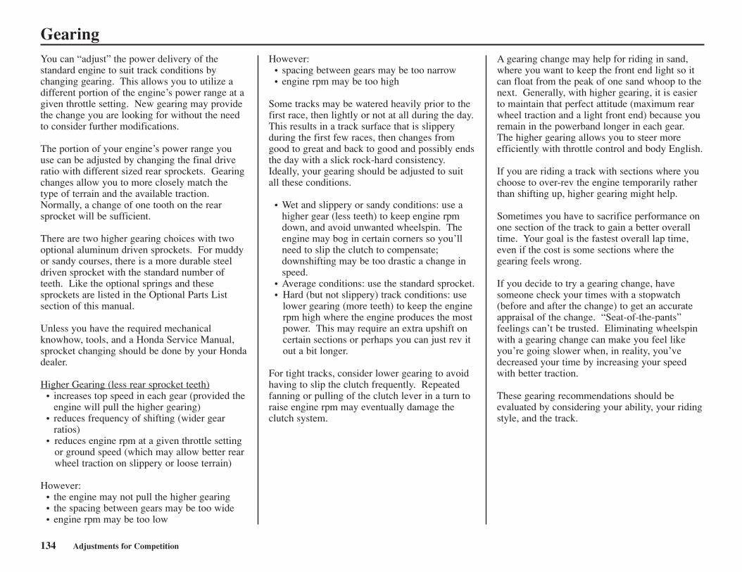
Gearing
134 Adjustments for Competition
You can “adjust” the power delivery of thestandard engine to suit track conditions bychanging gearing. This allows you to utilize adifferent portion of the engine’s power range at agiven throttle setting. New gearing may providethe change you are looking for without the needto consider further modifications.
The portion of your engine’s power range youuse can be adjusted by changing the final driveratio with different sized rear sprockets. Gearingchanges allow you to more closely match thetype of terrain and the available traction.Normally, a change of one tooth on the rearsprocket will be sufficient.
There are two higher gearing choices with twooptional aluminum driven sprockets. For muddyor sandy courses, there is a more durable steeldriven sprocket with the standard number ofteeth. Like the optional springs and thesesprockets are listed in the Optional Parts Listsection of this manual.
Unless you have the required mechanicalknowhow, tools, and a Honda Service Manual,sprocket changing should be done by your Hondadealer.
Higher Gearing (less rear sprocket teeth)• increases top speed in each gear (provided the
engine will pull the higher gearing)• reduces frequency of shifting (wider gear
ratios) • reduces engine rpm at a given throttle setting
or ground speed (which may allow better rearwheel traction on slippery or loose terrain)
However:• the engine may not pull the higher gearing• the spacing between gears may be too wide• engine rpm may be too low
However:• spacing between gears may be too narrow• engine rpm may be too high
Some tracks may be watered heavily prior to thefirst race, then lightly or not at all during the day.This results in a track surface that is slipperyduring the first few races, then changes fromgood to great and back to good and possibly endsthe day with a slick rock-hard consistency.Ideally, your gearing should be adjusted to suitall these conditions.
• Wet and slippery or sandy conditions: use ahigher gear (less teeth) to keep engine rpmdown, and avoid unwanted wheelspin. Theengine may bog in certain corners so you’llneed to slip the clutch to compensate;downshifting may be too drastic a change inspeed.
• Average conditions: use the standard sprocket.• Hard (but not slippery) track conditions: use
lower gearing (more teeth) to keep the enginerpm high where the engine produces the mostpower. This may require an extra upshift oncertain sections or perhaps you can just rev itout a bit longer.
For tight tracks, consider lower gearing to avoidhaving to slip the clutch frequently. Repeatedfanning or pulling of the clutch lever in a turn toraise engine rpm may eventually damage theclutch system.
A gearing change may help for riding in sand,where you want to keep the front end light so itcan float from the peak of one sand whoop to thenext. Generally, with higher gearing, it is easierto maintain that perfect attitude (maximum rearwheel traction and a light front end) because youremain in the powerband longer in each gear.The higher gearing allows you to steer moreefficiently with throttle control and body English.
If you are riding a track with sections where youchoose to over-rev the engine temporarily ratherthan shifting up, higher gearing might help.
Sometimes you have to sacrifice performance onone section of the track to gain a better overalltime. Your goal is the fastest overall lap time,even if the cost is some sections where thegearing feels wrong.
If you decide to try a gearing change, havesomeone check your times with a stopwatch(before and after the change) to get an accurateappraisal of the change. “Seat-of-the-pants”feelings can’t be trusted. Eliminating wheelspinwith a gearing change can make you feel likeyou’re going slower when, in reality, you’vedecreased your time by increasing your speedwith better traction.
These gearing recommendations should beevaluated by considering your ability, your ridingstyle, and the track.
Tire Selection for Track Conditions
Adjustments for Competition 135
Choosing the correct tire tread pattern and rubbercompound can affect your placing in competition.The tires on your motorcycle offer a “happymedium” for the variety of soil conditions themajority of riders are likely to encounter.
Experienced competitors often switch to tiresdeveloped for specific terrain conditions. If youdo switch, stay with the factory recommendedsizes. Other tires may affect handling oracceleration.
Be aware that tire sizes (width and aspect ratio)do vary from manufacturer to manufacturer oreven among tires made by the samemanufacturer. Variations in tires, especially thesidewall profile, can change the attitude of yourmotorcycle and its handling. Tire variations thatraise or lower the rear of your motorcycle have amore significant effect on handling thanvariations in front tires which, generally, don’tvary as much. Often, you can see or feel thechange in tire size. Another way to check is tomeasure the rolling circumference of the old andnew tires. A higher profile tire will have a largerrolling circumference.
If you do switch to tires designed for specialterrain use, remember they will be lessacceptable in other circumstances. For example,an aggressive mud tire will give excellent grip onwet, loamy terrain, but less impressive grip on ahard surface.
If you choose a tire with a sticky compound foradded traction, remember that it may transferadditional loads to the transmission because itgrips so well, especially when riding in situationsthat normally place unusual demands on thetransmission.
Complete consumer information can be obtainedfrom the various tire manufacturerrepresentatives and dealers.
Some general recommendations for specificterrain follow:
Hard, Slick SoilUse tires with many relatively short knobs thatare close together in order to obtain the largestpossible contact patch on the surface. The rubbercompound needs to be softer for hard ground inorder to hook up, but not so soft that the knobsroll over easily and affect holding a straight line.These tires tend to wear more quickly thanstandard tires because of the combination of softrubber and hard terrain.
Muddy SoilUse a more open tread pattern to avoid clogging. For these conditions, the relatively long knobswill probably be made from a harder rubbercompound to reduce any tendency to bend backunder acceleration or wear quickly.
Loose, Sandy SoilUse a tire that is similar in construction to thoseneeded for tacky soil and mud, but with a fewmore knobs.
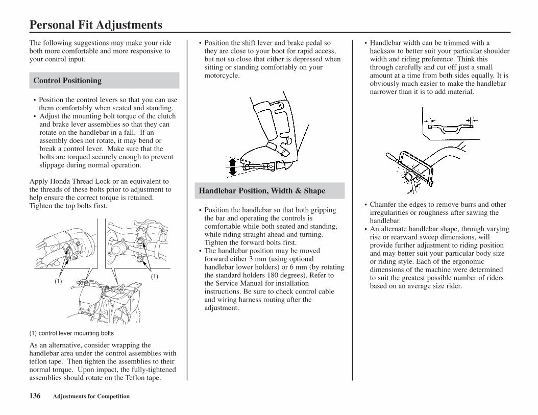
Personal Fit Adjustments
136 Adjustments for Competition
The following suggestions may make your rideboth more comfortable and more responsive toyour control input.
Control Positioning
• Position the control levers so that you can usethem comfortably when seated and standing.
• Adjust the mounting bolt torque of the clutchand brake lever assemblies so that they canrotate on the handlebar in a fall. If anassembly does not rotate, it may bend orbreak a control lever. Make sure that thebolts are torqued securely enough to preventslippage during normal operation.
Apply Honda Thread Lock or an equivalent tothe threads of these bolts prior to adjustment tohelp ensure the correct torque is retained.Tighten the top bolts first.
(1) control lever mounting bolts
As an alternative, consider wrapping thehandlebar area under the control assemblies withteflon tape. Then tighten the assemblies to theirnormal torque. Upon impact, the fully-tightenedassemblies should rotate on the Teflon tape.
• Position the shift lever and brake pedal sothey are close to your boot for rapid access,but not so close that either is depressed whensitting or standing comfortably on yourmotorcycle.
Handlebar Position, Width & Shape
• Position the handlebar so that both grippingthe bar and operating the controls iscomfortable while both seated and standing,while riding straight ahead and turning.Tighten the forward bolts first.
• The handlebar position may be movedforward either 3 mm (using optionalhandlebar lower holders) or 6 mm (by rotatingthe standard holders 180 degrees). Refer tothe Service Manual for installationinstructions. Be sure to check control cableand wiring harness routing after theadjustment.
• Chamfer the edges to remove burrs and otherirregularities or roughness after sawing thehandlebar.
• An alternate handlebar shape, through varyingrise or rearward sweep dimensions, willprovide further adjustment to riding positionand may better suit your particular body sizeor riding style. Each of the ergonomicdimensions of the machine were determinedto suit the greatest possible number of ridersbased on an average size rider.
(1)(1)
• Handlebar width can be trimmed with ahacksaw to better suit your particular shoulderwidth and riding preference. Think thisthrough carefully and cut off just a smallamount at a time from both sides equally. It isobviously much easier to make the handlebarnarrower than it is to add material.
Tips
Tips 137
Here’s helpful advice on how to transport andstore your Honda, as well as two troubleshootingflow charts.
Transporting Your Motorcycle .........................138Storing Your Motorcycle..................................139You & the Environment ...................................141Troubleshooting................................................142
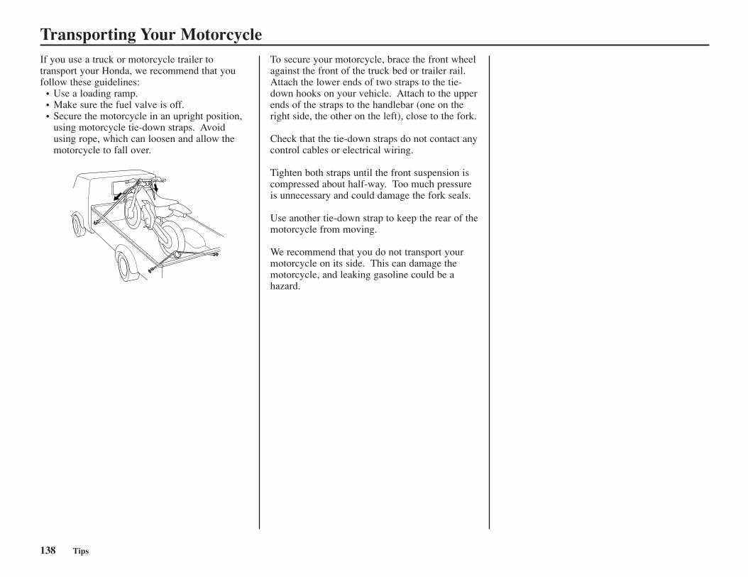
Transporting Your Motorcycle
138 Tips
If you use a truck or motorcycle trailer totransport your Honda, we recommend that youfollow these guidelines:
• Use a loading ramp.• Make sure the fuel valve is off.• Secure the motorcycle in an upright position,
using motorcycle tie-down straps. Avoidusing rope, which can loosen and allow themotorcycle to fall over.
To secure your motorcycle, brace the front wheelagainst the front of the truck bed or trailer rail.Attach the lower ends of two straps to the tie-down hooks on your vehicle. Attach to the upperends of the straps to the handlebar (one on theright side, the other on the left), close to the fork.
Check that the tie-down straps do not contact anycontrol cables or electrical wiring.
Tighten both straps until the front suspension iscompressed about half-way. Too much pressureis unnecessary and could damage the fork seals.
Use another tie-down strap to keep the rear of themotorcycle from moving.
We recommend that you do not transport yourmotorcycle on its side. This can damage themotorcycle, and leaking gasoline could be ahazard.
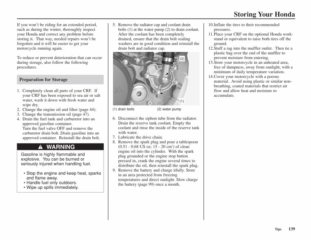
Storing Your Honda
Tips 139
WARNINGGasoline is highly flammable andexplosive. You can be burned orseriously injured when handling fuel.
• Stop the engine and keep heat, sparksand flame away.
• Handle fuel only outdoors.• Wipe up spills immediately.
5. Remove the radiator cap and coolant drainbolts (1) at the water pump (2) to drain coolant.After the coolant has been completelydrained, ensure that the drain bolt sealingwashers are in good condition and reinstall thedrain bolt and radiator cap.
10.Inflate the tires to their recommendedpressures.
11.Place your CRF on the optional Honda work-stand or equivalent to raise both tires off theground.
12.Stuff a rag into the muffler outlet. Then tie aplastic bag over the end of the muffler toprevent moisture from entering.
13.Store your motorcycle in an unheated area,free of dampness, away from sunlight, with aminimum of daily temperature variation.
14.Cover your motorcycle with a porousmaterial. Avoid using plastic or similar non-breathing, coated materials that restrict airflow and allow heat and moisture toaccumulate.
(2)
(1)
If you won’t be riding for an extended period,such as during the winter, thoroughly inspectyour Honda and correct any problem beforestoring it. That way, needed repairs won’t beforgotten and it will be easier to get yourmotorcycle running again.
To reduce or prevent deterioration that can occurduring storage, also follow the followingprocedures.
Preparation for Storage
1. Completely clean all parts of your CRF. Ifyour CRF has been exposed to sea air or saltwater, wash it down with fresh water andwipe dry.
2. Change the engine oil and filter (page 44).3. Change the transmission oil (page 47).4. Drain the fuel tank and carburetor into an
approved gasoline container.Turn the fuel valve OFF and remove thecarburetor drain bolt. Drain gasoline into anapproved container. Reinstall the drain bolt.
(1) drain bolts (2) water pump
6. Disconnect the siphon tube from the radiator.Drain the reserve tank coolant. Empty thecoolant and rinse the inside of the reserve tankwith water.
7. Lubricate the drive chain.8. Remove the spark plug and pour a tablespoon
(0.51 - 0.68 US oz; 15 - 20 cm3) of cleanengine oil into the cylinder. With the sparkplug grounded or the engine stop buttonpressed in, crank the engine several times todistribute the oil, then reinstall the spark plug.
9. Remove the battery and charge itfully. Storein an area protected from freezingtemperatures and direct sunlight. Slow chargethe battery (page 99) once a month.
Storing Your Honda
140 Tips
Removal from Storage
1. Uncover and clean your CRF.Change the engine and transmission oil ifmore than 4 months have passed since thestart of storage.
2. Uncover the end of the muffler and removethe rag from the muffler outlet.
3. Fill the fuel tank with recommended fuel (page 41).
4. Charge the battery (page 99) as required.Install the battery.
5. Pour a fresh recommended coolant mixture(page 48) slowly into the radiator filler holeup to the filler neck.Capacity:1.27 US qt (1.20R) at disassembly1.19 US qt (1.13R)at draining
Remove the radiator reserve tank cap and fillthe reserve tank to the upper level line.Bleed air from the system.
6. Perform all maintenance checks (page 11).
Tips 141
You & the EnvironmentOwning and riding a motorcycle can beenjoyable, but you must do your part to protectnature. When you show respect for the land,wildlife, and other people, you also help preservethe sport of off-road riding.
Following are tips on how you can be anenvironmentally-responsible motorcycle owner.
• Choose Sensible Cleaners. Use abiodegradable detergent when you wash yourmotorcycle. Avoid aerosol spray cleaners thatcontain chloroflur carbons (CFCs) whichdamage the atmosphere’s protective ozonelayer. Don’t throw cleaning solvents away;see the following guidelines for properdisposal.
• Recycle Wastes. It’s illegal and thoughtless toput used engine oil in the trash, down a drain,or on the ground. Used oil, gasoline, andcleaning solvents contain poisons that can hurtrefuse workers and contaminate our drinkingwater, lakes, rivers, and oceans.Before changing your oil, make sure you havethe proper containers. Put oil and other toxicwastes in separate sealed containers and takethem to a recycling center. Call your local orstate office of public works or environmentalservices to find a recycling center in your areaand get instructions on how to dispose ofnon-recyclable wastes.
Improper disposal of drained fluids is harmful tothe environment.
NOTICE
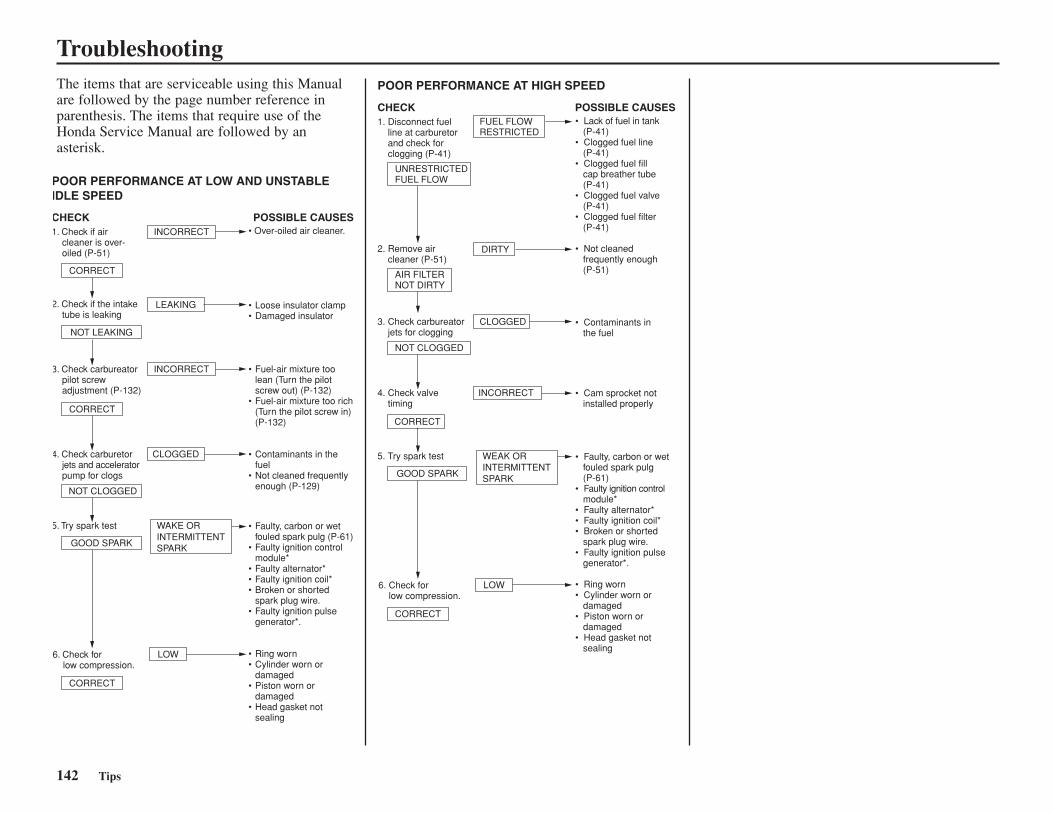
142 Tips
TroubleshootingThe items that are serviceable using this Manualare followed by the page number reference inparenthesis. The items that require use of theHonda Service Manual are followed by anasterisk.
POOR PERFORMANCE AT LOW AND UNSTABLEIDLE SPEED
CHECK POSSIBLE CAUSES1. Check if air cleaner is over- oiled (P-51)
CORRECT
INCORRECT
INCORRECT
LEAKING
CLOGGED
LOW
WAKE ORINTERMITTENTSPARK
CORRECT
CORRECT
NOT LEAKING
NOT CLOGGED
GOOD SPARK
2. Check if the intake tube is leaking
3. Check carbureator pilot screw adjustment (P-132)
4. Check carburetor jets and accelerator pump for clogs
5. Try spark test
6. Check for low compression.
• Over-oiled air cleaner.
• Loose insulator clamp• Damaged insulator
• Fuel-air mixture too lean (Turn the pilot screw out) (P-132)
• Fuel-air mixture too rich (Turn the pilot screw in) (P-132)
• Contaminants in the fuel
• Not cleaned frequently enough (P-129)
• Faulty, carbon or wet fouled spark pulg (P-61)
• Faulty ignition control module*
• Faulty alternator*• Faulty ignition coil*• Broken or shorted
spark plug wire.• Faulty ignition pulse
generator*.
• Ring worn• Cylinder worn or
damaged• Piston worn or
damaged• Head gasket not
sealing
POOR PERFORMANCE AT HIGH SPEED
CHECK POSSIBLE CAUSES1. Disconnect fuel line at carburetor and check for clogging (P-41)
UNRESTRICTEDFUEL FLOW
FUEL FLOWRESTRICTED
DIRTY2. Remove air cleaner (P-51)
AIR FILTERNOT DIRTY
• Lack of fuel in tank (P-41)• Clogged fuel line (P-41)• Clogged fuel fill cap breather tube (P-41)• Clogged fuel valve (P-41)• Clogged fuel filter (P-41) • Not cleaned frequently enough (P-51)
CLOGGED
INCORRECT
LOW
WEAK ORINTERMITTENTSPARK
NOT CLOGGED
CORRECT
CORRECT
GOOD SPARK
3. Check carbureator jets for clogging
4. Check valve timing
5. Try spark test
6. Check for low compression.
• Contaminants in the fuel
• Cam sprocket not installed properly
• Faulty, carbon or wet fouled spark pulg (P-61)• Faulty ignition control module*• Faulty alternator*• Faulty ignition coil*• Broken or shorted spark plug wire.• Faulty ignition pulse generator*.
• Ring worn• Cylinder worn or damaged• Piston worn or damaged• Head gasket not sealing
Taking Care of the Unexpected
Taking Care of the Unexpected 143
This section gives practical advice to help youproblems.
If a Fuse Blows ................................................144If Your Battery is Low (or Dead).....................145
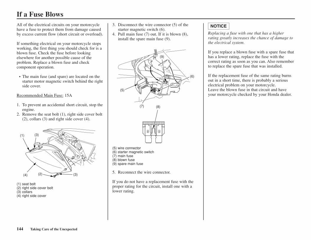
144 Taking Care of the Unexpected
If a Fuse BlowsAll of the electrical circuits on your motorcyclehave a fuse to protect them from damage causedby excess current flow (short circuit or overload).
If something electrical on your motorcycle stopsworking, the first thing you should check for is ablown fuse. Check the fuse before lookingelsewhere for another possible cause of theproblem. Replace a blown fuse and checkcomponent operation.
• The main fuse (and spare) are located on thestarter motor magnetic switch behind the rightside cover.
Recommended Main Fuse: 15A
1. To prevent an accidental short circuit, stop theengine.
2. Remove the seat bolt (1), right side cover bolt(2), collars (3) and right side cover (4).
(1) seat bolt(2) right side cover bolt(3) collars(4) right side cover
3. Disconnect the wire connector (5) of thestarter magnetic switch (6).
4. Pull main fuse (7) out. If it is blown (8),install the spare main fuse (9).
(5) wire connector(6) starter magnetic switch(7) main fuse(8) blown fuse(9) spare main fuse
5. Reconnect the wire connector.
If you do not have a replacement fuse with theproper rating for the circuit, install one with alower rating.
Replacing a fuse with one that has a higherrating greatly increases the chance of damage tothe electrical system.
If you replace a blown fuse with a spare fuse thathas a lower rating, replace the fuse with thecorrect rating as soon as you can. Also rememberto replace the spare fuse that was installed.
If the replacement fuse of the same rating burnsout in a short time, there is probably a seriouselectrical problem on your motorcycle.Leave the blown fuse in that circuit and haveyour motorcycle checked by your Honda dealer.
NOTICE
(1) (3)
(3)(2)(4)
(9)
(5)
(7)
(6)
(8)
If Your Battery is Low (or Dead)Jump-starting is not recommended, especially ifyou use an automobile battery.The greater amperage of an automobile batterywhen the car engine is running can damage yourmotorcycle’s electrical system.
Bump starting is also not recommended.
If you can’t charge the battery or it appearsunable to hold a charge, contact your Hondadealer.
Taking Care of the Unexpected 145

146 Taking Care of Unexpected
Technical Information 147
Technical InformationThis section contains dimensions, capacities, andother technical data.
Vehicle Identification .......................................148Specifications ...................................................149Torque Specifications.......................................151High Altitude Carburetor Adjustment ..............154Emission Control Systems ...............................155Oxygenated Fuels.............................................156Competition Logbook ......................................157Optional Parts List ...........................................159Spare Parts & Equipment.................................160Wiring Diagram................................................161
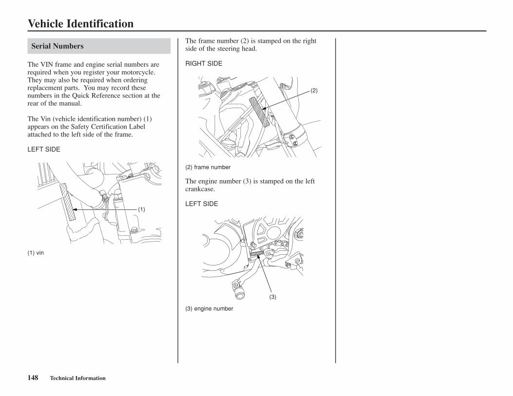
148 Technical Information
Vehicle Identification
Serial Numbers
The VIN frame and engine serial numbers arerequired when you register your motorcycle.They may also be required when orderingreplacement parts. You may record thesenumbers in the Quick Reference section at therear of the manual.
The Vin (vehicle identification number) (1)appears on the Safety Certification Labelattached to the left side of the frame.
LEFT SIDE
(1) vin
The frame number (2) is stamped on the rightside of the steering head.
RIGHT SIDE
(2) frame number
The engine number (3) is stamped on the leftcrankcase.
LEFT SIDE
(3) engine number
(1)
(2)
(3)
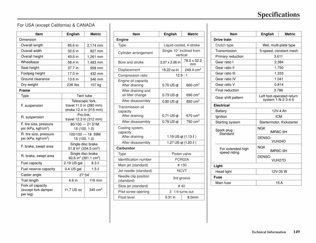
Technical Information 149
Specifications
Overall length
Overall width
Overall height
Wheelbase
Seat height
Footpeg height
Ground clearance
Dry weight
Item English
85.6 in
32.6 in
49.6 in
58.4 in
37.7 in
17.0 in
13.6 in
236 Ibs
Metric
Type
Dimension
Frame
Fork oil capacity (except fork damperper leg)
F. suspension
R. suspension
F. tire size, pressure psi (kPa, kgf/cm2)
R. tire size, pressure psi (kPa, kgf/cm2)
F. brake, swept area
R. brake, swept area
Fuel capacity
Caster angle
Trail length
Twin tube
Telescopic fork, travel 11.0 in (280 mm) stroke 12.4 in (315 mm)
Pro-link, travel 12.3 in (312 mm)
80/100 — 21 51M 15 (100, 1.0)
100/100 — 18 59M 15 (100, 1.0)
Single disc brake 51.8 in2 (334.5 cm2)
Single disc brake 60.6 in2 (391.1 cm2)
27 54
2.19 US gal
4.6 in
11.7 US oz 345 cm3
116 mm
8.3R
Fuel reserve capacity 0.4 US gal 1.5R
Item English
3.07 x 2.06 in
0.31 in
Cylinder arrangement
Bore and stroke
Displacement
Compression ratio
Engine oil capacity After draining
After draining and oil filter change
After disassembly
After disassembly
Transmission oilcapacity After draining
Type
Identification number
Main jet (standard)
Jet needle (standard)
Piston valve
FCR02A
# 130
NCVT
Needle clip position (standard)
Slow jet (standard)
Pilot screw opening
Float level
Liquid cooled, 4-stroke
3rd groove
# 40
2 1/4 turns out
Type
Metric
660 cm3
690 cm3
850 cm3
670 cm3
750 cm3
78.0 x 52.2mm
8.0mm
Engine
Carburetor
12.9 : 1
Clutch type
Transmission
Primary reduction
Gear ratio I
Gear ratio II
Gear ratio III
Gear ratio IV
Gear ratio V
Final reduction
Item English Metric
Drive train
Electrical
Wet, multi-plate type
5-speed, constant mesh
3.611
2.384
1.750
1.333
1.041
0.814
3.786
NGK
DENSO
NGK
DENSO
Gear shift pattern
Ignition
Starting system
Spark plug : Standard
For extended highspeed riding
ICM
Startermotor, Kickstarter
Battery 12V-4 Ah
Light
Head light 12V-35 W
Fuse
Main fuse 15 A
Left foot-operated return system 1-N-2-3-4-5
IMR8C-9H
VUH24D
IMR9C-9H
VUH27D
2,174 mm
827 mm
1,261 mm
1,483 mm
958 mm
432 mm
346 mm
107 kg
15.22 cu-in
0.70 US qt
0.73 US qt
0.90 US qt
0.71 US qt
0.79 US qt
249.4 cm3
After disassembly
Cooling system,capacity After draining 1.19 US qt (1.13R)
1.27 US qt (1.20R)
For USA (except California) & CANADA
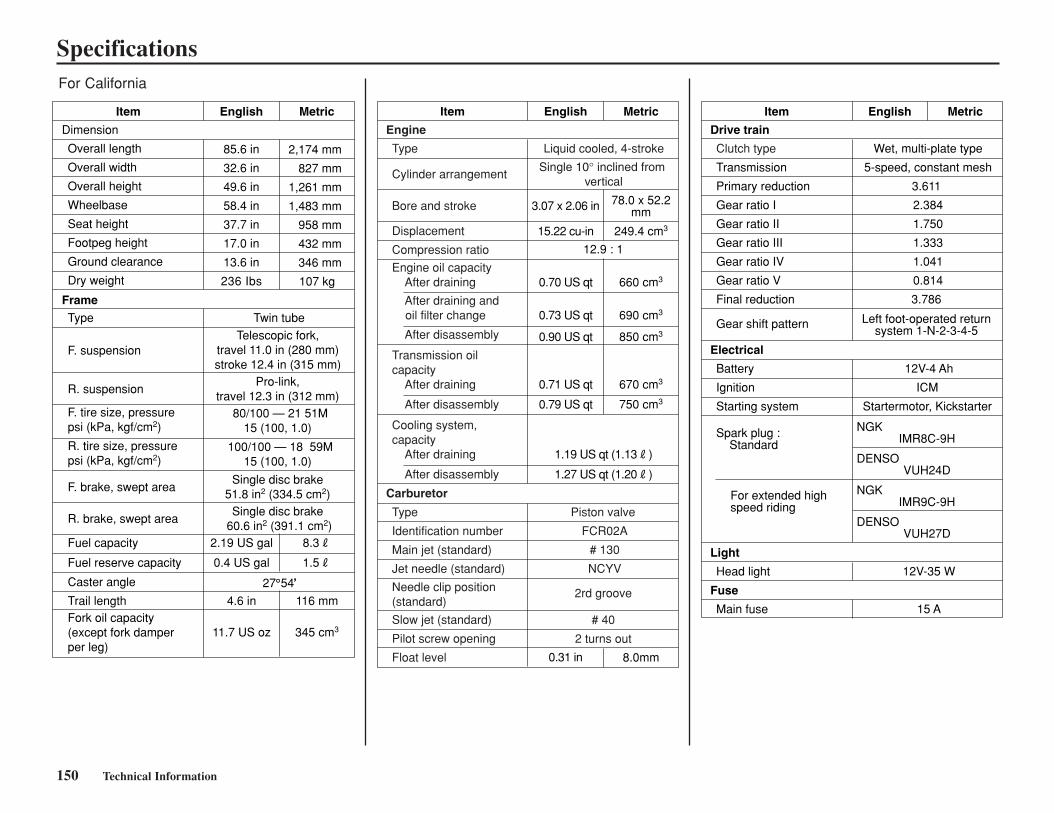
Specifications
150 Technical Information
27 54
Overall length
Overall width
Overall height
Wheelbase
Seat height
Footpeg height
Ground clearance
Dry weight
Item English
85.6 in
32.6 in
49.6 in
58.4 in
37.7 in
17.0 in
13.6 in
236 Ibs
Metric
Type
Dimension
Frame
Fork oil capacity (except fork damperper leg)
F. suspension
R. suspension
F. tire size, pressure psi (kPa, kgf/cm2)
R. tire size, pressure psi (kPa, kgf/cm2)
F. brake, swept area
R. brake, swept area
Fuel capacity
Caster angle
Trail length
Twin tube
Telescopic fork, travel 11.0 in (280 mm) stroke 12.4 in (315 mm)
Pro-link, travel 12.3 in (312 mm)
80/100 — 21 51M 15 (100, 1.0)
100/100 — 18 59M 15 (100, 1.0)
Single disc brake 51.8 in2 (334.5 cm2)
Single disc brake 60.6 in2 (391.1 cm2)
2.19 US gal
4.6 in
11.7 US oz 345 cm3
116 mm
8.3R
Fuel reserve capacity 0.4 US gal 1.5R
Item English
3.07 x 2.06 in
0.31 in
Cylinder arrangement
Bore and stroke
Displacement
Compression ratio
Engine oil capacity After draining
After draining and oil filter change
After disassembly
After disassembly
Transmission oilcapacity After draining
Type
Identification number
Main jet (standard)
Jet needle (standard)
Piston valve
FCR02A
# 130
NCYV
Needle clip position (standard)
Slow jet (standard)
Pilot screw opening
Float level
Liquid cooled, 4-stroke
2rd groove
# 40
2 turns out
Type
Metric
660 cm3
690 cm3
850 cm3
670 cm3
750 cm3
78.0 x 52.2mm
8.0mm
Engine
Carburetor
12.9 : 1
Clutch type
Transmission
Primary reduction
Gear ratio I
Gear ratio II
Gear ratio III
Gear ratio IV
Gear ratio V
Final reduction
Item English Metric
Drive train
Electrical
Wet, multi-plate type
5-speed, constant mesh
3.611
2.384
1.750
1.333
1.041
0.814
3.786
NGK
DENSO
NGK
DENSO
Gear shift pattern
Ignition
Starting system
Spark plug : Standard
For extended highspeed riding
ICM
Startermotor, Kickstarter
Battery 12V-4 Ah
Light
Head light 12V-35 W
Fuse
Main fuse 15 A
Left foot-operated return system 1-N-2-3-4-5
IMR8C-9H
VUH24D
IMR9C-9H
VUH27D
2,174 mm
827 mm
1,261 mm
1,483 mm
958 mm
432 mm
346 mm
107 kg
15.22 cu-in
0.70 US qt
0.73 US qt
0.90 US qt
0.71 US qt
0.79 US qt
249.4 cm3
After disassembly
Cooling system,capacity After draining 1.19 US qt (1.13R)
1.27 US qt (1.20R)
For California
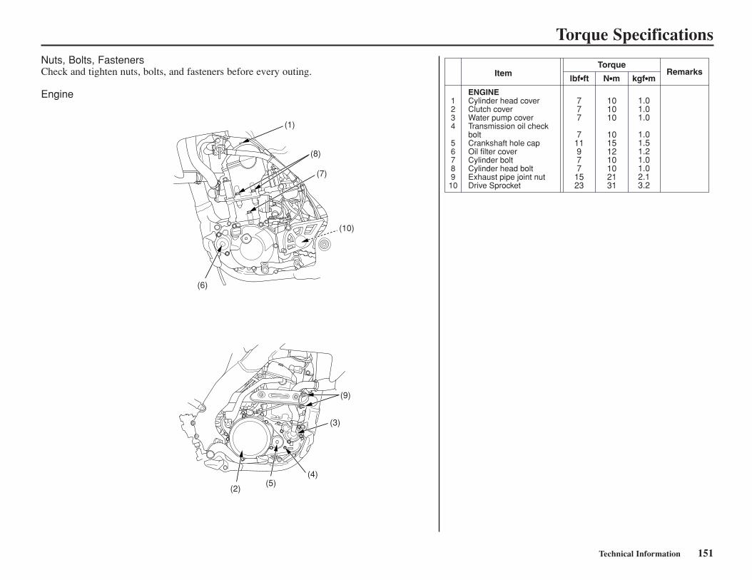
Technical Information 151
Torque SpecificationsNuts, Bolts, FastenersCheck and tighten nuts, bolts, and fasteners before every outing.
Engine
Item
1234
56789
10
ENGINECylinder head coverClutch coverWater pump coverTransmission oil check boltCrankshaft hole capOil filter coverCylinder boltCylinder head boltExhaust pipe joint nutDrive Sprocket
TorqueRemarks
lbf•ft N•m kgf•m
777
711977
1523
101010
10151210102131
1.01.01.0
1.01.51.21.01.02.13.2
(9)
(3)
(4)(5)
(2)
(1)
(8)
(7)
(10)
(6)
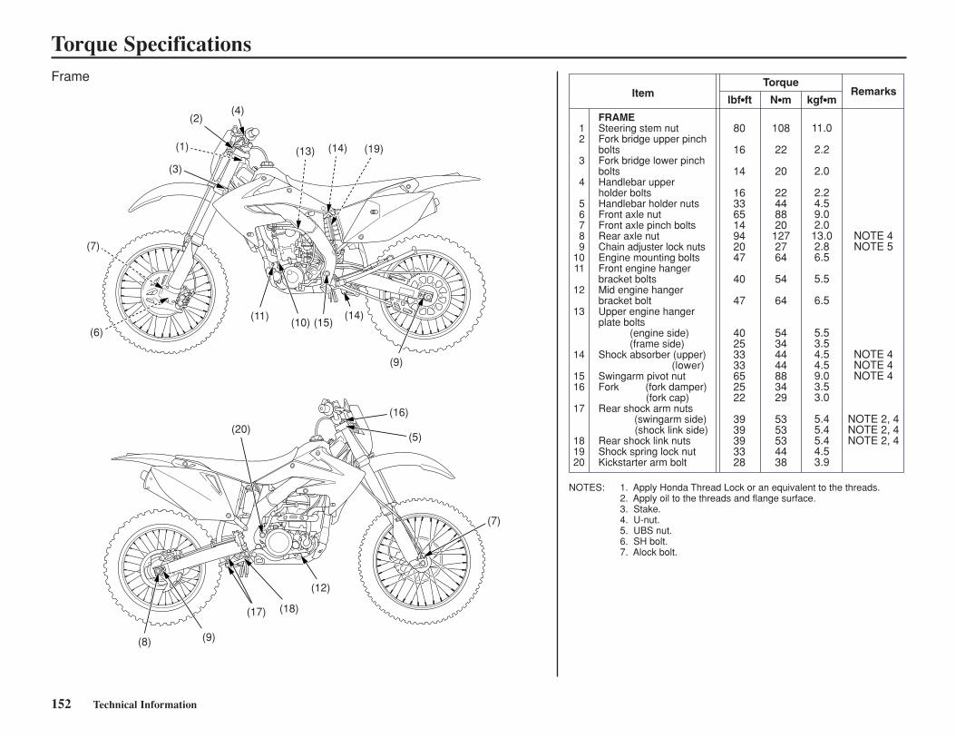
152 Technical Information
Torque SpecificationsFrame
Item
12
3
4
56789
1011
12
13
14
1516
17
181920
FRAMESteering stem nutFork bridge upper pinchboltsFork bridge lower pinchboltsHandlebar upperholder boltsHandlebar holder nutsFront axle nutFront axle pinch boltsRear axle nutChain adjuster lock nutsEngine mounting boltsFront engine hangerbracket boltsMid engine hangerbracket boltUpper engine hangerplate bolts (engine side) (frame side)Shock absorber (upper) (lower) Swingarm pivot nutFork (fork damper) (fork cap)Rear shock arm nuts
(swingarm side)(shock link side)
Rear shock link nutsShock spring lock nutKickstarter arm bolt
TorqueRemarks
lbf•ft N•m kgf•m
80
16
14
16336514942047
40
47
40253333652522
3939393328
108
22
20
22448820
1272764
54
64
54344444883429
5353534438
11.0
2.2
2.0
2.24.59.02.0
13.02.86.5
5.5
6.5
5.53.54.54.59.03.53.0
5.45.45.44.53.9
NOTE 4NOTE 5
NOTE 4NOTE 4NOTE 4
NOTE 2, 4NOTE 2, 4NOTE 2, 4
1. Apply Honda Thread Lock or an equivalent to the threads. 2. Apply oil to the threads and flange surface. 3. Stake. 4. U-nut. 5. UBS nut. 6. SH bolt. 7. Alock bolt.
NOTES:
(6)
(7)
(3)
(1)
(2)(4)
(13)
(11)
(20)
(16)
(5)
(7)
(12)
(18)
(9)(8)
(10) (15)(14)
(9)
(14) (19)
(17)
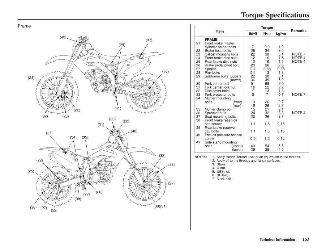
Technical Information 153
Torque Specifications
Item
21
2223242526272829
3031323334
35363738
39
40
41
FRAMEFront brake mastercylinder holder boltsBrake hose boltsCaliper mounting boltsFront brake disc nutsRear brake disc nutsBrake pedal pivot boltSpokesRim locksSubframe bolts (upper) (Iower)Fork center boltFork center lock nutDisc cover boltsFork protector boltsMuffler mountingbolts (front) (rear)Muffler clamp boltSprocket nutsSeat mounting boltsFront brake reservoircap screwsRear brake reservoircap boltsFork air pressure releasescrewSide stand mounting bolts (upper) (lower)
TorqueRemarks
lbf•ft N•m kgf•m
725221212202.79.422365116 95
1919152420
1.1
1.1
0.9
4029
9.93430161626
3.681330496922137
2626213226
1.5
1.5
1.2
5439
1.03.53.11.61.62.6
0.381.33.15.07.02.21.30.7
2.72.72.13.32.7
0.15
0.15
0.12
5.54.0
NOTE 7NOTE 4NOTE 4
NOTE 7
NOTE 4
1. Apply Honda Thread Lock or an equivalent to the threads. 2. Apply oil to the threads and flange surfaces. 3. Stake. 4. U-nut. 5. UBS nut. 6. SH bolt. 7. Alock bolt.
NOTES:
Frame
(40)(37)
(36)
(21)
(38) (22)
(40)
(33)
(28)
(27)
(26)(22)
(22)(27)(28)
(25)
(22)
(37)(34) (35)
(39)
(30)(31)
(22)
(23)(32)
(24)
(29)
(41)
When operating this motorcycle at high altitude,the air-fuel mixture becomes overly rich.
Above 6,500 feet (2,000 m), driveability andperformance may be reduced and fuelconsumption increased. The carburetor can bemodified to compensate for this high altituderichness.
However, the carburetor must be returned tostandard factory specifications when loweraltitude riding is desired. See your Honda dealerfor high altitude modification.
Sustained operation at altitudes below 5,000 feet(1,500 m) with high altitude carburetormodifications may cause engine overheating anddamage.
154 Technical Information
High Altitude Carburetor Adjustment
NOTICE
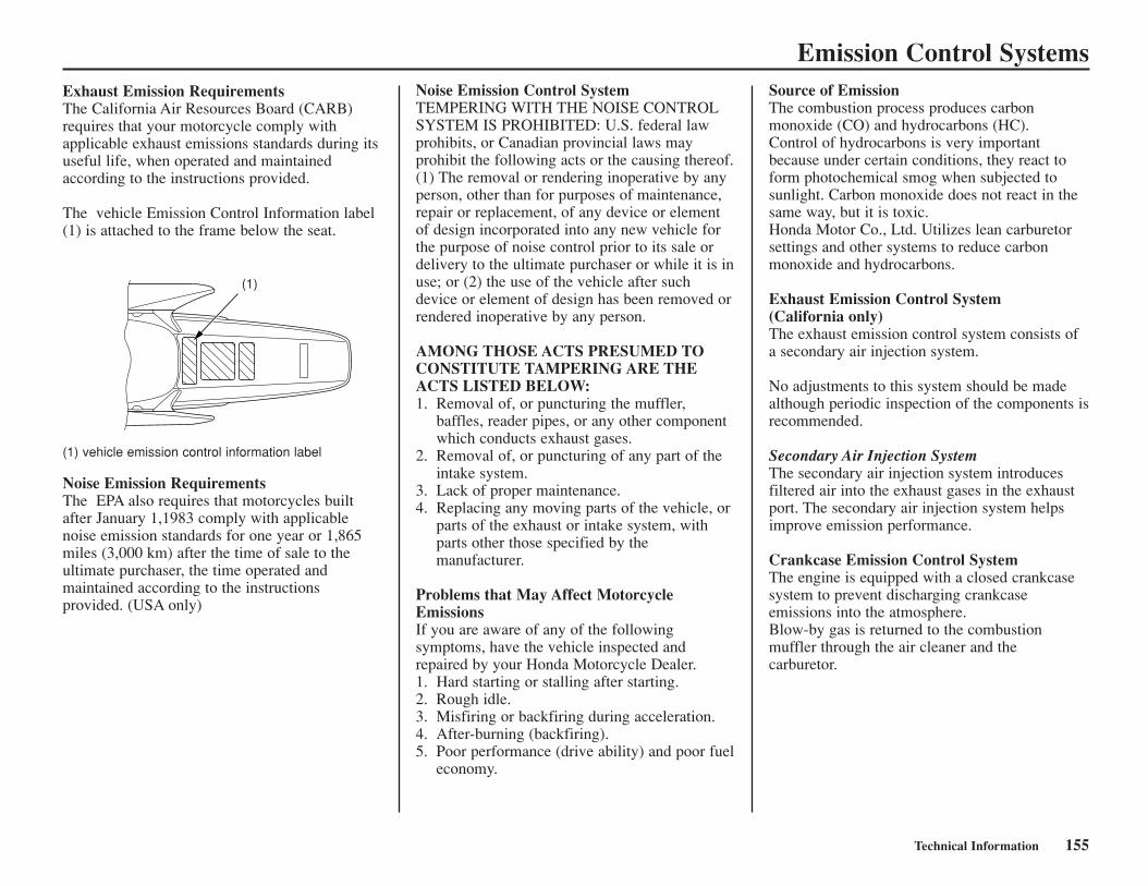
Emission Control SystemsExhaust Emission RequirementsThe California Air Resources Board (CARB)requires that your motorcycle comply withapplicable exhaust emissions standards during itsuseful life, when operated and maintainedaccording to the instructions provided.
The vehicle Emission Control Information label(1) is attached to the frame below the seat.
Technical Information 155
(1) vehicle emission control information label
Noise Emission RequirementsThe EPA also requires that motorcycles builtafter January 1,1983 comply with applicablenoise emission standards for one year or 1,865miles (3,000 km) after the time of sale to theultimate purchaser, the time operated andmaintained according to the instructionsprovided. (USA only)
Noise Emission Control SystemTEMPERING WITH THE NOISE CONTROLSYSTEM IS PROHIBITED: U.S. federal lawprohibits, or Canadian provincial laws mayprohibit the following acts or the causing thereof.(1) The removal or rendering inoperative by anyperson, other than for purposes of maintenance,repair or replacement, of any device or elementof design incorporated into any new vehicle forthe purpose of noise control prior to its sale ordelivery to the ultimate purchaser or while it is inuse; or (2) the use of the vehicle after suchdevice or element of design has been removed orrendered inoperative by any person.
AMONG THOSE ACTS PRESUMED TOCONSTITUTE TAMPERING ARE THEACTS LISTED BELOW:1. Removal of, or puncturing the muffler,
baffles, reader pipes, or any other componentwhich conducts exhaust gases.
2. Removal of, or puncturing of any part of theintake system.
3. Lack of proper maintenance.4. Replacing any moving parts of the vehicle, or
parts of the exhaust or intake system, withparts other those specified by themanufacturer.
Problems that May Affect MotorcycleEmissionsIf you are aware of any of the followingsymptoms, have the vehicle inspected andrepaired by your Honda Motorcycle Dealer.1. Hard starting or stalling after starting.2. Rough idle.3. Misfiring or backfiring during acceleration.4. After-burning (backfiring).5. Poor performance (drive ability) and poor fuel
economy.
Source of EmissionThe combustion process produces carbonmonoxide (CO) and hydrocarbons (HC).Control of hydrocarbons is very importantbecause under certain conditions, they react toform photochemical smog when subjected tosunlight. Carbon monoxide does not react in thesame way, but it is toxic.Honda Motor Co., Ltd. Utilizes lean carburetorsettings and other systems to reduce carbonmonoxide and hydrocarbons.
Exhaust Emission Control System(California only)The exhaust emission control system consists ofa secondary air injection system.
No adjustments to this system should be madealthough periodic inspection of the components isrecommended.
Secondary Air Injection SystemThe secondary air injection system introducesfiltered air into the exhaust gases in the exhaustport. The secondary air injection system helpsimprove emission performance.
Crankcase Emission Control SystemThe engine is equipped with a closed crankcasesystem to prevent discharging crankcaseemissions into the atmosphere.Blow-by gas is returned to the combustionmuffler through the air cleaner and thecarburetor.
(1)
156 Technical Information
Oxygenated FuelsSome conventional gasolines are being blendedwith alcohol or an ether compound. Thesegasolines are collectively referred to asoxygenated fuels. To meet clean air standards,some areas of the United States and Canada useoxygenated fuels to help reduce emissions.
If you use an oxygenated fuel, be sure it isunleaded and meets the minimum octane ratingrequirement.
Before using an oxygenated fuel, try to confirmthe fuel’s contents. Some states/provincesrequire this information to be posted on thepump.
The following are the EPA-approved percentagesof oxygenates:
ETHANOL (ethyl or grain alcohol) 10% byVolumeYou may use gasoline containing up to 10%ethanol by volume. Gasoline containing ethanolmay be marketed under the name “Gasohol”.
MTBE (Methyl Tertiary Butyl Ether) 15% byVolumeYou may use gasoline containing up to 15%MTBE by volume.
METHANOL (methyl or wood alcohol) 5% byVolumeYou may use gasoline containing methanolcontaining up to 15% methanol by volume aslong as it contains cosolvents and corrosioninhibitors to protect the fuel system. Gasolinecontaining more than 5% methanol by volumemay cause starting and/or performance problems.It may also damage metal, rubber, and plasticparts of your fuel system.
If you notice any undesirable operatingsymptoms, try another service station or switchto another brand of gasoline.
Fuel system damage or performance problemsresulting from the use of an oxygenated fuelcontaining more than the percentages ofoxygenates mentioned above are not coveredunder warranty.
Oxygenated the fuels can damage paint andplastic. Be careful not to spill fuel when fillingthe fuel tank. Wipe up any spills immediately.
Oxygenated fuels can damage paint and plastic.
NOTICE

Consumer Information 157
Competition LogbookAny serious competition effort relies heavily onthe knowledge gained and compiled fromprevious racing events. The best way to organizethe many bits of information is to record them ina logbook.
Your logbook can include such information assuspension adjustments, gearing, and tireselection. This detailed information, along withyour comments, can prove valuable when youcompete at the same track or on similar terrain.
Your logbook can also tell you whenmaintenance was performed and when it will benecessary again. Your logbook also lets yourecord any repairs and lets you keep track of therunning time on the engine and suspensioncomponents.
If you choose to sell your motorcycle, theaccurate maintenance records in your logbookmight be the deciding deal-maker for a potentialbuyer.
Consider using different color pens or pencils torecord important information on specificsubjects. For example, record results in black, inred, suspension/chassis settings in blue, andgearing selections in green. Color codes willhelp you identify the information you want witha glance.
Tuning & Adjustment RecordsKeep track of the settings and adjustments thatworked best at a particular location. These itemsinclude:
• basic track conditions, altitude, andtemperature
• suspension settings• chassis adjustments tested and selected• gearing• tire selection• air pressure
Competition Records• your placings• thoughts to improve performance next time:
both yours and your motorcycle’s• strategy notes
Maintenance Records• regular interval maintenance• repairs• running time on engine• running time on suspension components
TimekeepingThis Manual lists maintenance intervals forevery-so-many races or every-so-many hours ofrunning.
Because all races are not the same, the mosteffective way to schedule maintenance is by thehours you have run your CRF.
An official “guestimate” is close enough for ourtimekeeping purposes. You may choose to recordyour time the same way aircraft operators do (butwithout the benefit of an electrical hourmeter).All running time is broken down into hours andtenths of an hour (each six minutes representsone tenth of an hour).
Racing RecordsInformation worth recording for this section ofyour logbook may include:
• Your placing in each moto and overallfinishing position.
• Thoughts on what you could do to improveyour performance next time.
• Notes on any patterns noted in choice ofstarting gate positions or in riding portions ofthe course as the day progressed that mayprove helpful in future events.
• Any places on the course where you chose thewrong line and were passed too easily.
• Notes on strategy used by your competition orby riders in another event that are worthremembering.
Maintenance RecordsRegular maintenance items you’ll want to recordin your logbook should include:
• Dates and results of cylinder, piston and ringexaminations
• Patterns for frequency of need fordecarbonization with a particular oil
• When you last performed shock linkage andswingarm pivot bearing maintenance
• Engine, transmission, and suspension oilchanges
• chain, sprocket, chain guide and sliderreplacements
• coolant changes and related componentreplacements
• Spark plug, brake pad and control cablereplacements
In addition, you should record any irregularitiesnoted in component wear so you’ll remember tokeep a close eye on these areas in the future.
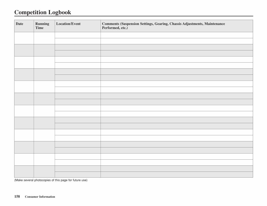
158 Consumer Information
Date Running Location/Event Comments (Suspension Settings, Gearing, Chassis Adjustments, Maintenance Time Performed, etc.)
(Make several photocopies of this page for future use)
Competition Logbook
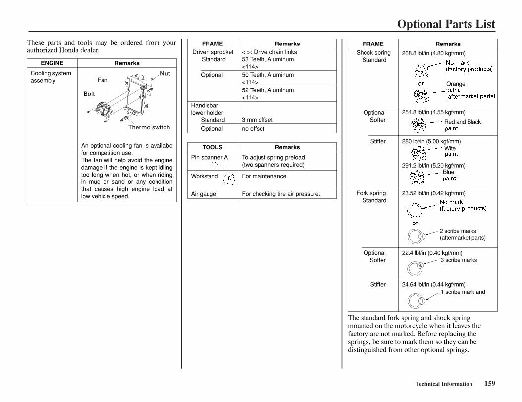
Technical Information 159
Optional Parts List
FRAME Remarks
Shock spring Standard
Stiffer
OptionalSofter
Stiffer
Fork spring Standard
OptionalSofter
The standard fork spring and shock spring mounted on the motorcycle when it leaves the factory are not marked. Before replacing the springs, be sure to mark them so they can be distinguished from other optional springs.
268.8 lbf/in (4.80 kgf/mm)
No mark(factory products)
Redpaint(aftermarket parts)
or
254.8 lbf/in (4.55 kgf/mm)
23.52 lbf/in (0.42 kgf/mm)
22.4 lbf/in (0.40 kgf/mm)
24.64 lbf/in (0.44 kgf/mm)
FRAME RemarksDriven sprocket
Standard< >: Drive chain links 53 Teeth, Aluminum.<114>
Optional 50 Teeth, Aluminum <114>
Optional no offset
52 Teeth, Aluminum <114>
Handlebar lower holder
Standard 3 mm offset
TOOLS Remarks
For checking tire air pressure.
Pin spanner A
Workstand
To adjust spring preload. (two spanners required)
For maintenance
Air gauge
ENGINE Remarks
Cooling systemassembly Orange
Red and Black
280 lbf/in (5.00 kgf/mm)
291.2 lbf/in (5.20 kgf/mm)
Wite
Blue
These parts and tools may be ordered from your authorized Honda dealer.
An optional cooling fan is availabe for competition use.The fan will help avoid the engine damage if the engine is kept idling too long when hot, or when riding in mud or sand or any condition that causes high engine load at low vehicle speed.
2 scribe marks(aftermarket parts)
3 scribe marks
1 scribe mark and
Bolt
FanNut
Thermo switch
160 Technical Information
Spare Parts & EquipmentThere are numerous spare parts you can take toan event to help ensure you get in a full day ofriding. In addition to the usual nuts and bolts,consider the following:
Spare Parts
spark plugsair cleaner (clean & oiled, sealed in a plastic bag)chain & masterlinkschain guide sliderchain guidechain rollersinner tubes (front & rear)fendersfootpegsfront visor & side covershandlebargripslevers (brake, clutch & hot start)clutch lever handlebar mountclutch cablehot start cablethrottle assemblythrottle cableshift leverbrake pedalspokes (front & rear, each side)sprockets (smaller than standard, for gearingchanges & collision damage replacement) assorted nuts, bolts, washers, screws, cotter pinsheadlight bulbs battery fuses
Additional Sparesfront brake assemblyrear brake assemblywheels & tires (front & rear, mounted)clutch disc and platesengine & transmission oil
seatignition componentstop end-completeradiator hosesradiator shrouds (L & R)brake hoses (front & rear)
General Tools
sockets (3/8 in drive)screwdrivers: blade & Phillips No. 1, 2, 3wrench, large adjustablewrenches: open end & boxwrenches: hex (Allen)wrench, spoketorque wrench (metric scale, click-stop style)pliers: standard, needle-nose, channel-lock sethammer, plastic headsyringe with adjustable stoptire pressure gaugetire ironstire pump or air tankfeeler gauge setvernier caliper (metric)pressure/vacuum testing equipment (USA only)
Honda Special Tools
Any special tools for your motorcycle purchasedfrom your Honda dealer.• Clutch Center Holder 07724-0050001 or
07724-0050002• Lock Nut Wrench 07WMA-KZ30100• Tensioner Stopper 070MG-0010100• Nipple Wrench 07JMA-MR60100
Chemical Products
Pro Honda GN4, HP4 (without molybdenum
additives) or HP4M (with molybdenumadditives) 4-stroke Oil(Engine Oil)Pro Honda HP Trans Oil or Pro Honda GN4 orHP4 (without molybdenum additives only) 4-stroke Oil (Transmission Oil)Honda thread LockPro Honda HP Fork Oil 5WHonda Brake Fluid Pro Honda Chain Lube Pro Honda Foam Filter OilHonda brite cleaner Honda Contact CleanerHonda Dielectric Compound Honda Hand Grip Cement Honda Hondalock Honda Moly 60 Paste (U.S.A. only) ormolybdenum disulfide paste (containing morethan 40% molybdenum disulfide additive) White Lithium Grease Wheel Bearing Grease Silicone Sealerhigh-temperature greaseantifreeze
Other Products
pliers-safety wiresafety wiremechanic’s wireduct tapeplastic tie-wrapshose clampsdrop lightelectrical tape
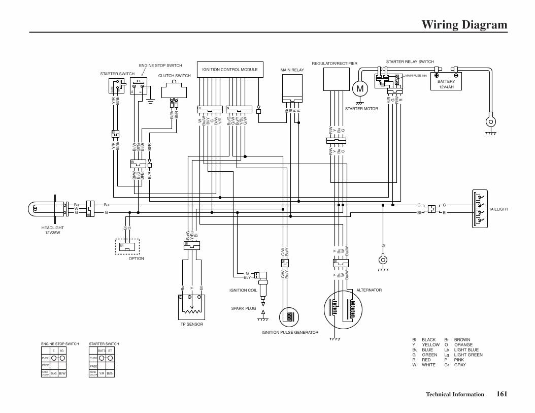
Technical Information 161
Wiring Diagram

162 Technical Information
Consumer Information 163
Consumer InformationThis section contains information aboutcontacting Honda and how to get an officialHonda service manual.
Authorized Manuals .........................................164Contacting Honda.............................................165Your Honda Dealer...........................................166The Honda Rider’s Club (USA only) ..............167
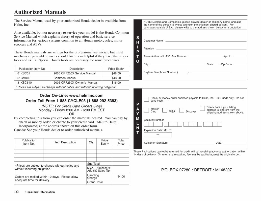
Publication Item Description Qty.
Price TotalItem No. Each* Price
Sub TotalMich. Purchasers Add 6% Sales Tax
Handling $4.00ChargeGrand Total
164 Consumer Information
The Service Manual used by your authorized Honda dealer is available fromHelm, Inc.
Also available, but not necessary to service your model is the Honda CommonService Manual which explains theory of operation and basic serviceinformation for various systems common to all Honda motorcycles, motorscooters and ATVs.
These Honda manuals are written for the professional technician, but mostmechanically-capable owners should find them helpful if they have the propertools and skills. Special Honda tools are necessary for some procedures.
Order On-Line: www.helminc.comOrder Toll Free: 1-888-CYCLE93 (1-888-292-5393)
(NOTE: For Credit Card Orders Only)Monday - Friday 8:00 AM - 6:00 PM EST
ORBy completing this form you can order the materials desired. You can pay by
check or money order, or charge to your credit card. Mail to Helm,Incorporated, at the address shown on this order form.
Canada: See your Honda dealer to order authorized manuals.
Authorized Manuals
Publication Item No. Description Price Each*
61KSC01 2005 CRF250X Service Manual $48.00
61CM002 Common Manual $48.00
31KSC610 2005 CRF250X Owner’s Manual $16.00
*Prices are subject to change without notice and without incurring obligation.
*Prices are subject to change without notice andwithout incurring obligation.
Orders are mailed within 10 days. Please allowadequate time for delivery.
SHIPTO
NOTE: Dealers and Companies, please provide dealer or company name, and alsothe name of the person to whose attention the shipment should be sent. Forpurchases outside U.S.A., please write to the address shown below for a quotation.
Customer Name
Attention
Street Address-No P.O. Box Number Apt. #
City State Zip Code
Daytime Telephone Number ( )
PAYMENT
Check or money order enclosed payable to Helm, Inc. U.S. funds only. Do notsend cash.
MasterCard
Account Number
VISAVISA Discover
Check here if your billingaddress is different from theshipping address shown above.
Expiration Date: Mo. Yr
Customer Signature Date
—
These Publications cannot be returned for credit without receiving advance authorization within14 days of delivery. On returns, a restocking fee may be applied against the original order.
P.O. BOX 07280 • DETROIT • MI 48207
Consumer Information 165
Your owner’s manual was written to cover mostof the questions you might ask about yourHonda. Any questions not answered in theowner’s manual can be answered by your Hondadealer. If he doesn’t have the answer right away,he will get it for you.
If you have a difference of opinion with yourdealer, please remember that each dealership isindependently owned and operated. That’s whyit’s important to work to resolve any differencesat the dealership level.
If you wish to comment on your experiences withyour Honda or with your dealer, please send yourcomments to the following address (USA only):
Motorcycle Division, American Honda MotorCo., Inc., P.O. Box 2220, Torrance CA 90509-2220, mailstop: 100-4W-5B, telephone: (310) 532-9811.
Canada: Refer to the warrantly booklet that wassupplied with your vehicle.
Please include the following information in yourletter:
• name, address, and telephone number• product model, year, and frame/VIN serial
number• date of purchase• dealer name and address
We will likely ask your Honda dealer to respond,or possibly acknowledge your comments directly.
Contacting Honda
166 Consumer Information
Your Honda DealerOnce you purchase your new Honda, get familiarwith the organization of your Honda dealer soyou can utilize the full range of servicesavailable.
The service department is there to performregular maintenance and unexpected repairs. Ithas the latest available service information fromHonda.
The parts department offers Genuine Hondaparts, Pro Honda products, Hondaline accessories(USA only), and Honda accessories and products(Canada only). The same quality that went intoyour Honda can be found in Genuine Hondareplacement parts. You’ll also find comparablequality in the accessories and products availablefrom the parts department.
Your dealer can inform you about competitionevents in your area. You’ll also find that yourdealer is a source of information (USA only) theHonda Rider’s Club of America.
We’re sure you’ll be as pleased with the serviceyour Honda dealer continues to provide after thesale as you are with the quality and dependabilityof your Honda.
Consumer Information 167
The Honda Rider’s Club (USA only)One of the best ways to get the most enjoymentfrom owning and riding your Honda is throughthe Honda Rider’s Club of America. Yourpurchase of a new motorcycle, scooter, ATV orPWC from a participating U.S. Honda dealerentitles you to a complimentary one-yearmembership in the club. There are handreds ofHRCA Chapter sponsoring dealers across theUSA with events and activities almost everyweekend. Membership benefits include:
• 24-hour emergency roadside assistance foryour new Honda (includes roodside assistancefor your transport vehicles as long as yourHonda is aboard or in tow).
• Vehicle transport to the nearest Honda dealeror service center, if necessary.
• An exclusive HRCA website complete withaccess to the official Honda Common ServiceManual, contests, insider information andmore.
• Reimbursement (up to $75) for MotorcycleSafety Foundation training. Separate freetraining from the Speialty Vehicle Institute ofAmerica for ATV owners.
• One full year of the Honda Red Ridermagazine or Honda Red Rider ATV (for ATVpurchasers).
• Discounts from HRCA partners forexperienced rider courses.
• Discounted vehicle insurance from theHRCA’s insurance partner.
• Racing contingency programs and assistanceat selected dual-sport, off-road, and motocrossevents.
Contact your Honda dealer for more informationor call: 1 800-847-HRCA or log on to www.hrca. honda. com.
Table of ContentsThe following presents the contents of eachsection of your owner’s manual.
MOTORCYCLE SAFETY...............................1Important Safety Precautions..... .........................2Loading................................................................3Accessories & Modifications ..............................4Safety Labels .......................................................5
OPERATING CONTROLS .............................7Component Locations .........................................8
BEFORE RIDING ............................................9Are You Ready to Ride? ...................................10Is Your Motorcycle Ready to Ride?..... .............11
Pre-ride Inspection.......................................11
BASIC OPERATING INSTRUCTIONS ......13Safe Riding Precautions ....................................14Starting & Stopping the Engine ........................15
Preparation ...................................................15Fuel Valve ....................................................15Starting Procedure .......................................15Flooded Engine............................................16How to Stop the Engine...............................16
Shifting Gears....................................................17Braking ..............................................................18Parking ..............................................................19Post-ride Inspection...........................................20Brake-in Guidelines ..........................................21
SERVICING YOUR HONDA........................23Before You Service Your HondaThe Importance of Maintenance .......................24Maintenance Safety...........................................25
Important Safety Precautions........................25Maintenance Schedule ......................................26General Competition Maintenance ...................30Before & After Competition Maintenance........33
Between Motos & Practice Maintenance .....33After Competition Maintenance ...................33
Service PreparationsComponent Locations .......................................35Seat Removal ....................................................36Fuel Tank Removal ...........................................37Subframe Upright Position................................39
Service Procedures
Fluids & FiltersFuel System.......................................................41Engine Oil .........................................................43Transmission Oil ...............................................46Coolant ..............................................................48Air Cleaner ........................................................51Crankcase Breather ...........................................53
EngineThrottle ..............................................................54Clutch System ...................................................56Hot Start Lever..................................................60Spark Plug .........................................................61Exhaust Pipe/Muffler ........................................62Spark Arrester....................................................65Valve Clearance.................................................66Piston/Piston Rings/Piston Pin..........................74
ChassisSuspension.........................................................82
Front Suspension Inspection.........................82Rear Suspension Inspection..........................83Recommended Fork Oil................................84Fork Oil Change ...........................................84
Brakes................................................................86Wheels...............................................................90Tires & Tubes ....................................................91Side Stand..........................................................93Drive Chain .......................................................94Additional Maintenance Procedures .................97
ElectricalBattery ...............................................................99Headlight & Taillight ......................................100Appearance Care .............................................101
ADJUSTMENTS FOR COMPETITION ...103Front Suspension Adjustments........................104Rear Suspension Adjustments .........................118Suspension Adjustments for Track
Conditions ...................................................122Suspension Adjustments Guidelines ...............123Carburetor Adjustments & Tuning Tips..........126Chassis Adjustments........................................133Gearing ............................................................134Tire Selection for Track Conditions................135Personal Fit Adjustments ................................136
TAKING CARE OF THEUNEXPECTED.........................................143
If a Fuse Blows ...............................................144If Your Battery is Low (or Dead)....................145
168 Table of Contents

Table of ContentsTECHNICAL INFORMATION ..................147Vehicle Identification ......................................148Specifications ..................................................149Torque Specifications......................................151High Altitude Carburetor Adjustment .............154Emission Control Systems ..............................155Oxygenated Fuels............................................156Competition Logbook .....................................157Optional Parts List ..........................................159Spare Parts & Equipment................................160Wiring Diagram...............................................161
CONSUMER INFORMATION...................163Authorized Manuals ........................................164Contacting Honda............................................165Your Honda Dealer..........................................166The Honda Rider’s Club (USA only) .............167
Table of Contents 169
170 Index
accessories ...........................................................4adjustments,
altitude and temperature .............................154carburetor....................................................132chassis .........................................................133control free play.............................54,56,60,86for competition ...........................................103gearing ........................................................134high altitude carburetor ..............................154personal fit ..................................................136suspension, front.........................................104suspension, rear...........................................118suspension, track conditions.......................135tire selection..................................................91
after competition maintenance...........................33air cleaner...........................................................51air pressure,
front suspension..........................................104tires ...............................................................91
American Honda, contacting ...........................165apparel, protective................................................2coolant................................................................48appearance care................................................101authorized manuals ..........................................164
basic operation ...................................................13before riding.........................................................9between motos & practice maintenance............33 brakes,
fluid level......................................................87lever, front adjustment..................................86pad wear........................................................89pedal height ..................................................86
break·in guidelines.............................................21
capacity, fuel ......................................................41carburetor,
adjustment...................................................132circuit functions ..........................................126 components .................................................126 disassembly/assembly.................................129high altitude adjustment .............................154idle speed ....................................................132
care, appearance...............................................101chain drive .........................................................94chassis adjustment for track conditions...........135choke knob.........................................................15cleaner, air..........................................................51cleaning, appearance care ................................101clutch system, adjustment..................................56consumer information......................................163controls, operating ...............................................7component locations,
maintenance ..................................................35operating controls ...........................................8
competition logbook ........................................157contacting Honda .............................................165controls, operating ...............................................8coolant................................................................48customer service ..............................................163cylinder system ..................................................76
damping adjustments,front ............................................................104rear ..............................................................118
dealer, your Honda...........................................166diagram, wiring................................................161drive chain .........................................................94
engine,flooded ..........................................................43idle speed ....................................................132number ........................................................148pinging ..........................................................41starting ..........................................................15stop button ....................................................16stopping ........................................................16won’t start .....................................................16
environment, protecting...................................141
filter,air .................................................................51oil .................................................................44
flooded engine, starting .....................................16fork,
front suspension adjustment .......................104front suspension inspection ..........................82oil recommendation ......................................84
frame number...................................................148front brake lever adjustment ..............................86front suspension maintenance..........................104fuel,
line ................................................................41filter ..............................................................41recommendation ...........................................41refueling........................................................41system ...........................................................41oxygenated..................................................156tank capacity .................................................41valve..............................................................15
F
E
D
C
B
A
Index
Index 171
Index
gap, spark plug...................................................61gasohol ...............................................................41gasoline ..............................................................41gearing .............................................................134guidelines, suspension adjustment...................123
handlebar inspection ..........................................97high altitude carburetor adjustment .................154Honda,
contacting....................................................165Rider’s Club................................................167Service Manual ...........................................164your dealer ..................................................166
identification, vehicle ......................................148idle speed, engine ............................................132inspection, pre·ride.............................................11
labels, safety ........................................................5locations, component ...........................................8logbook, competition .......................................157
maintenance,after competition...........................................33before & after competition ...........................34between motos & practice ............................33general competition ......................................29importance ....................................................24safety.............................................................25schedule ...................................................27,28
manual, service ................................................164modifications .......................................................4
oil,fork................................................................82transmission ..................................................46
operating,controls ...........................................................7
optional,parts list ......................................................159sprockets .....................................................159
oxygenated fuels ..............................................156
pads, brake .........................................................89parts, optional ..................................................159personal fit adjustments ...................................136pinging, engine ..................................................41plug, spark..........................................................61pre-load, rear suspension .................................118pre·ride inspection..............................................11protective apparel.................................................2
rear suspension maintenance .............................83Rider’s Club Honda .........................................167riding,
apparel ............................................................2basic operation..............................................13before ..............................................................9important safety information ..........................2safety precautions ...........................................2
safety,a few words about..................Safety Messagesimportant information.....................................2important precautions .....................................2labels ...............................................................5maintenance ..................................................25riding precautions .........................................14
schedule, maintenance ..................................27,28serial numbers..................................................148service,
customer......................................................163manuals .......................................................164
spare parts ........................................................160spark knock........................................................41spark plug...........................................................61
maintenance ..................................................61specifications ............................................149,150spring pre-load, rear suspension ......................118starting,
engine............................................................15troubleshooting .............................................16
steering stem inspection.....................................97stopping engine..................................................16storage..............................................................139subframe.............................................................39
S
R
P
O
M
L
I
H
G
172 Index
Indexsuspension,
front ..............................................................82rear ................................................................83
suspension adjustment,front ............................................................104rear ..............................................................118for track conditions.....................................135guidelines....................................................123
transmission oil ..................................................46tuning tips ........................................................126throttle,
freeplay .........................................................54inspection......................................................55
tires,air pressure....................................................91flat .................................................................91selection ........................................................92
tools..................................................................160torque specifications.................................151-153transporting ......................................................138troubleshooting ................................................142tubes, replacing ..................................................91
valve, fuel ..........................................................15vehicle identification .......................................148
washing your motorcycle.................................101weight limit..........................................................3wheels ................................................................90writing diagram................................................161
W
V
T

Memo 173
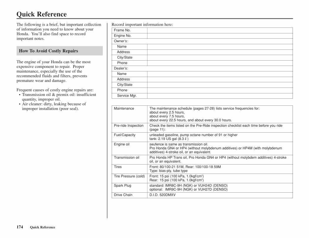
174 Quick Reference
The maintenance schedule (pages 27-28) lists service frequencies for: about every 2.5 hours,about every 7.5 hours, about every 22.5 hours, and about every 30.0 hours.
Check the items listed on the Pre-Ride inspection checklist each time before you ride(page 11):
unleaded gasoline, pump octane number of 91 or highertank: 2.19 US gal (8.3R)
seufence is same as transmission oil.Pro Honda GN4 or HP4 (without molybdenum additives) or HP4M (with molybdenumadditives) 4-stroke oil, or an equivalent.
Pro Honda HP Trans oil, Pro Honda GN4 or HP4 (without molybdem additives) 4-strokeoil, or an equivalent.
Front: 80/100-21 51M, Rear: 100/100-18 59MType: bias-ply, tube type
Front: 15 psi (100 kPa, 1.0kgf/cm2)Rear: 15 psi (100 kPa, 1.0kgf/cm2)
standard: IMR8C-9H (NGK) or VUH24D (DENSO)optional: IMR9C-9H (NGK) or VUH27D (DENSO)
D.I.D. 520DMXV
Maintenance
Pre-ride Inspection
Fuel/Capacity
Engine oil
Transmission oil
Tires
Tire Pressure (cold)
Spark Plug
Drive Chain
Quick ReferenceRecord important information here:
Frame No.
Engine No.
Owner’s:
Name
Address
City/State
Phone
Dealer’s:
Name
Address
City/State
Phone
Service Mgr.
The following is a brief, but important collectionof information you need to know about yourHonda. You’ll also find space to recordimportant notes.
How To Avoid Costly Repairs
The engine of your Honda can be the mostexpensive component to repair. Propermaintenance, especially the use of therecommended fluids and filters, preventspremature wear and damage.
Frequent causes of costly engine repairs are: • Transmission oil & premix oil: insufficient
quantity, improper oil.• Air cleaner: dirty, leaking because of
improper installation (poor seal).