Homework of Chapter (4.1) - Islamic University of...
14
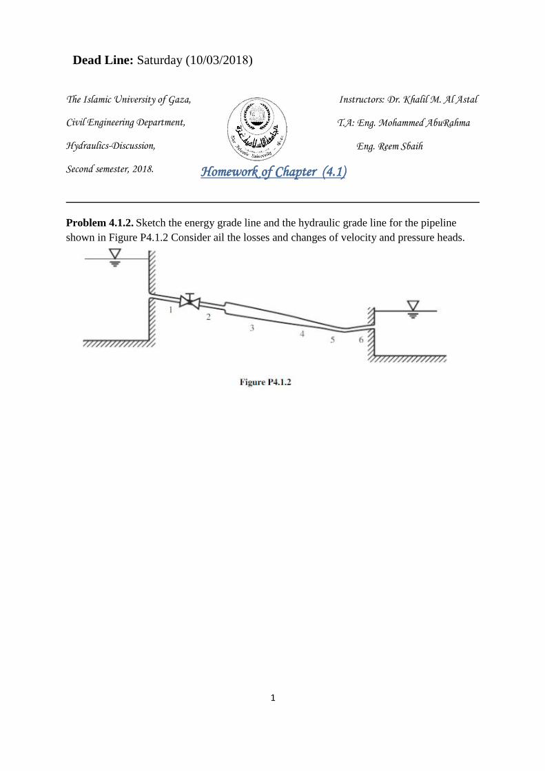
1 The Islamic University of Gaza, Instructors: Dr. Khalil M. Al Astal T.A: Eng. Mohammed AbuRahma Eng. Reem Sbaih Homework of Chapter (4.1) Problem 4.1.2. Sketch the energy grade line and the hydraulic grade line for the pipeline shown in Figure P4.1.2 Consider ail the losses and changes of velocity and pressure heads. Dead Line: Saturday (10/03/2018) Civil Engineering Department, Hydraulics-Discussion, Second semester, 2018.
Transcript of Homework of Chapter (4.1) - Islamic University of...
1
The Islamic University of Gaza, Instructors: Dr. Khalil M. Al Astal
T.A: Eng. Mohammed AbuRahma
Eng. Reem Sbaih
Homework of Chapter (4.1)
Problem 4.1.2. Sketch the energy grade line and the hydraulic grade line for the pipeline
shown in Figure P4.1.2 Consider ail the losses and changes of velocity and pressure heads.
Dead Line: Saturday (10/03/2018)
Civil Engineering Department,
Hydraulics-Discussion,
Second semester, 2018.

2
Problem 4.1.5. Determine the elevation of the upstream reservoir (A) in Figure P4.1.2 if the
downstream reservoir (B) is at 750 m, the flow rate (water at 20°C) through the smooth
concrete pipeline is 1.2 m3/sec, given the following:
pipes 1 and 2:100 m long ( D= 0.5 m) valves 1-2: fully open globe valve
expansion 2-3: D = 0.5 m to l.0 m pipe 3: 100m long (D = 1.0 m)
confusor 4: loss coefficient of 0.3 pipe 5: 50 m long ( D = 0. 5
bend 5-6: loss coefficient of 0.2 pipe 6: 50 m long ( D = 0. 5 m)

3
Problem 4.1.13. The 40-m-long, 4-in. commercial steel pipe connects reservoirs A and Bas
shown in Figure P4.l.6. If the pressure at point 1 is 39.3 kPa, what is the pressure P 0 at
reservoir A? Assume the water is at 20°C, all valves are fully open, and bend losses are
negligible.
4
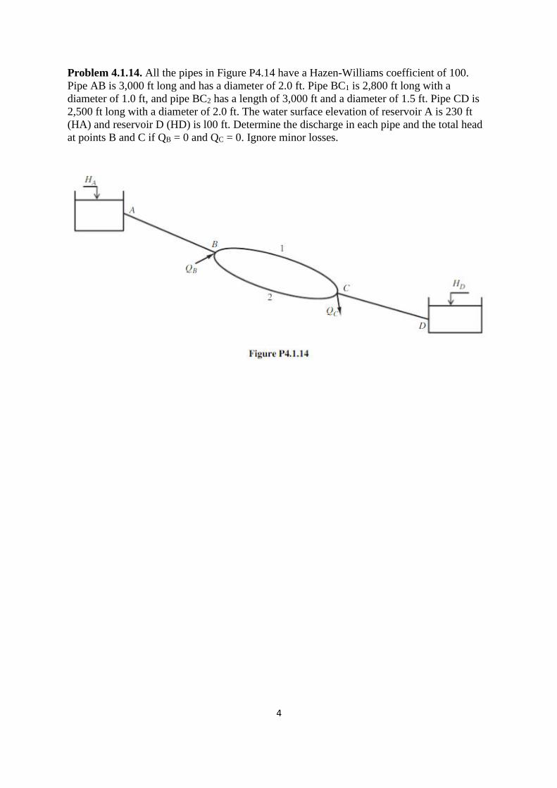
Problem 4.1.14. All the pipes in Figure P4.14 have a Hazen-Williams coefficient of 100.
Pipe AB is 3,000 ft long and has a diameter of 2.0 ft. Pipe BC1 is 2,800 ft long with a
diameter of 1.0 ft, and pipe BC2 has a length of 3,000 ft and a diameter of 1.5 ft. Pipe CD is
2,500 ft long with a diameter of 2.0 ft. The water surface elevation of reservoir A is 230 ft
(HA) and reservoir D (HD) is l00 ft. Determine the discharge in each pipe and the total head
at points B and C if QB = 0 and QC = 0. Ignore minor losses.
5
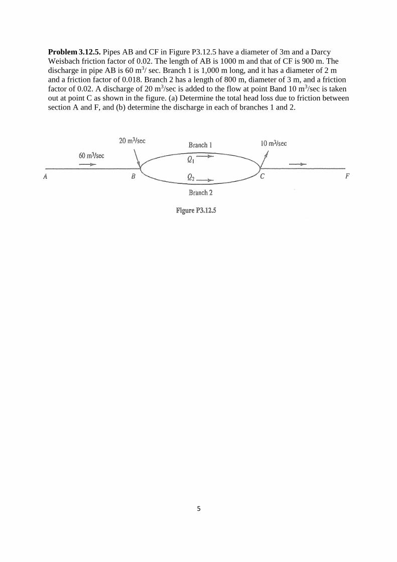
Problem 3.12.5. Pipes AB and CF in Figure P3.12.5 have a diameter of 3m and a Darcy
Weisbach friction factor of 0.02. The length of AB is 1000 m and that of CF is 900 m. The
discharge in pipe AB is 60 m3/ sec. Branch 1 is 1,000 m long, and it has a diameter of 2 m
and a friction factor of 0.018. Branch 2 has a length of 800 m, diameter of 3 m, and a friction
factor of 0.02. A discharge of 20 m3/sec is added to the flow at point Band 10 m3/sec is taken
out at point C as shown in the figure. (a) Determine the total head loss due to friction between
section A and F, and (b) determine the discharge in each of branches 1 and 2.

6
Problem 4.2.1. Water flows in a new 20-cm, 300-m-long ductile iron pipe between reservoirs
A and B, as shown in Figure P4.2.1. The pipe is elevated at S, which is 150 m downstream
from reservoir A. The water surface in reservoir B is 25 m below the water surface in
reservoir A. If Δs = 7.0 m, is cavitation a concern?

7
Problem 4.2.5. A confusor is installed in a 40-cm pipe. Immediately upstream from the
confusor the water pressure is 84,000 N/m2 . Determine the minimum diameter of the
confusor outlet that will keep the pressure head at the outlet above-8 m when the flow rate is
440 L/sec. (Note: The -8 m of gauge pressure is the threshold for dissolved gases in the water
to begin vaporizing and disrupting the flow.)

8
Problem 4.2.10. Water flows in a new 20-cm-diameter, 300-m-long ductile iron pipe
between reservoirs A and B, as shown in Figure P4.2.l . The pipe is elevated at S, which is
150 m downstream from reservoir A. The water surface difference between the two reservoirs
is 25 m. Determine the head that should be provided by a booster pump 100 m downstream
from reservoir A if Δs is 3 m and the pressure head at that location must be kept above -6 m
because of cavitation concerns. Sketch the EGL and the HGL for the pipeline.

9
Problem 4.3.3. Determine flow rates in the branching pipe system depicted in Figure P4.3.2
given the following WS elevation and pipe data (lengths and diameters):
WS1 = 2,100 m L1 = 5,000 m D1 = 1.0 m
WS2 = 2,080 m L2 = 4,000 m D2 = 0.3 m
WS3 = 2,060 m L3 = 5,000 m D3 = 1.0 m

10
Problem 4.3.6. Two rooftop cisterns supply a tropical bungalow with shower water. The
water surface in the uppermost cistern (A) is 8m above the ground, and the water surface in
the lower cistern (B) is 7 m above the ground. They both supply water to a junction below !he
lowest cistern's water surface through 3-cm PVC tubes (n = 0.011 ). Each tube is 2m long.
A 5-m supply line leads from the junction through another 3-cm PVC rube to a pan shower
(essentially a reservoir with holes in the bottom) 3 m above the ground. What flow rate can
be expected in the shower in liters per second?
11
Problem 4.3.8. The highest reservoir in a three-reservoir branching system is inaccessible
after a mountain storm. Determine the surface elevation of this reservoir given the following
water surface elevation and pipe data (lengths 'and diameters):
WS1 =? Ll = 2,000 m Dl = 0.30 m
WS2 = 4,080 m L2 = 1,000 m D2 = 0.20 m
WS3 = 4,060 m L3 = 3,000 m D3 = 0.50m
All of the pipes are rough concrete (e = 0.6 mm), so complete turbulence is assumed. The
actual elevation of the junction (J) is 4,072, and the pressure at the junction is 127 kPa

12
Additional problems:
Problem (1 )
1. In the shown figure below, all pipes are 8-cm in diameter cast iron (e = 0.26mm).
Determine the flow rate from reservoir 1 if valve C is a) closed and b) open with k = 0.5.
13
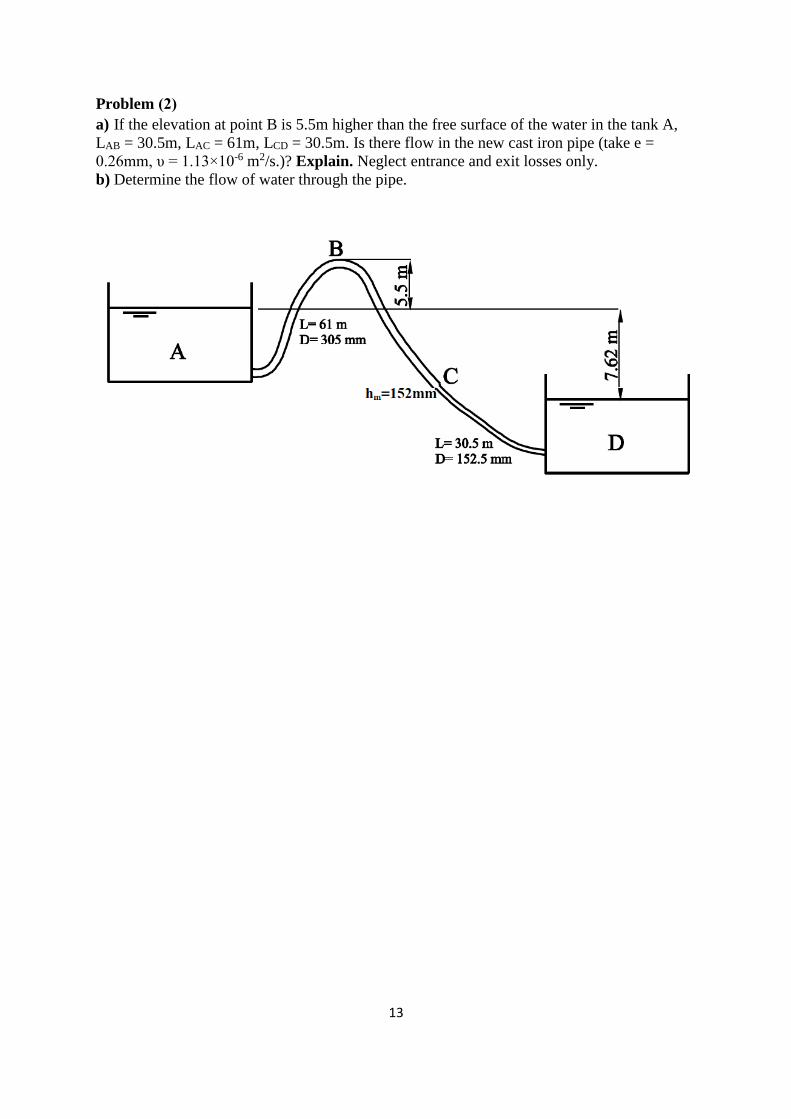
Problem (2 )
a) If the elevation at point B is 5.5m higher than the free surface of the water in the tank A,
LAB = 30.5m, LAC = 61m, LCD = 30.5m. Is there flow in the new cast iron pipe (take e =
0.26mm, υ = 1.13×10⁻⁶ m2/s.)? Explain. Neglect entrance and exit losses only.
b) Determine the flow of water through the pipe.

14
Problem (3 )
In the shown figure, if the length of the pipe between reservoir A and point B is 180 m and the
absolute pressure at point B is 7.3 m. Calculate the distance S if the minor loss coefficient (K)
of the valve at point C is 9.
Given data:
The entrance is sharp edged.
Total length of pipe (L= 730 m), Pipe diameter (d = 150mm), friction factor (f = 0.02).