The Odyssey ByHomer No Not This Homer!! The Famous Greek Poet Homer.

[ ]
Homer Tidal Power and Marine Instrument Test Station
Interim Report
By:
Dan Boone
Drew Nielson
Ian Dorman
Matt Madsen
Michael Hamman
Sava White
Weiran Man
March 8, 2013

[i]
Table of Contents Abstract ......................................................................................................................................................... 1
Acknowledgements ....................................................................................................................................... 2
Introduction .................................................................................................................................................. 3
Project Context ......................................................................................................................................... 3
Scope and Schedule .................................................................................................................................. 4
Organization ............................................................................................................................................. 5
Hydrokinetic Overview ............................................................................................................................. 7
Opportunities ................................................................................................................................................ 8
Design and Evaluation Criteria ...................................................................................................................... 8
Site Conditions .............................................................................................................................................. 9
Alternative Concepts ................................................................................................................................... 11
Alternatives Analysis ................................................................................................................................... 11
Alternative 1 - Dock Mounted ................................................................................................................ 11
Alternative 2 - Floating ........................................................................................................................... 15
Barge .................................................................................................................................................. 16
Pontoon .............................................................................................................................................. 18
Conclusion ................................................................................................................................................... 20
Appendix A - Cradle System ........................................................................................................................ 21
Appendix B - Literature Review .................................................................................................................. 22
Appendix C - Instrumentation and Environmental Monitoring .................................................................. 23
Appendix D - Schedule ................................................................................................................................ 27
References .................................................................................................................................................. 28

[1]
Abstract
The Homer Tidal Incubator project began in 2012 as a group of Homer proponents, agency
representatives, and industry professionals started meeting to discuss the potential of utilizing the
Homer Deep Water Dock as a tidal generator testing station. The City of Homer is sponsoring a
project with the University of Alaska Anchorage (UAA) School of Engineering as part of the
working group, offering advice and directing resources from an engineering capstone class to
further the feasibility investigation. The UAA capstone engineering class examined various
potential solutions and selected two test station alternatives for research and discussion. The two
alternatives, which include a facility fixed on the Homer Deep Water Dock and a floating system
based at the dock, appear viable and are undergoing further investigation. Through exploring the
advantages and disadvantages of implementation for each alternative reported by the engineering
students, The City of Homer and the Homer Tidal Incubator working group are enabled to select
the preferred option for the UAA engineering capstone class to complete the design to 35%.

[2]
Acknowledgements We would like to thank the following sponsors for their contributions to the project:
Paul Seaton
Alaska State Representative
Katie Koester
Community and Economic Development Coordinator
Bryan Hawkins
Port Director/Harbormaster
Aaron Glidden
Port MaintenanceSupervisor
Carey Meyer
Public Works Director
Homer City Council
Homer Tidal Energy Incubator Working Group
We would also like to thank the following mentors and contributors for their support:
Orson Smith, PhD, PE
Professor, UAA School of Engineering
Thomas Ravens, PhD
Professor, UAA School of Engineering
Mark Swanson
Prince William Sound Regional Citizens Advisory Council Executive Director
Mike Tracy
HEA engineer
Terry Thompson
Kachemak Bay Research Reserve Manager
He Liu, PhD
Professor, UAA School of Engineering
Jens Munk, PhD
Professor, UAA School of Engineering
Introduction
Project Context
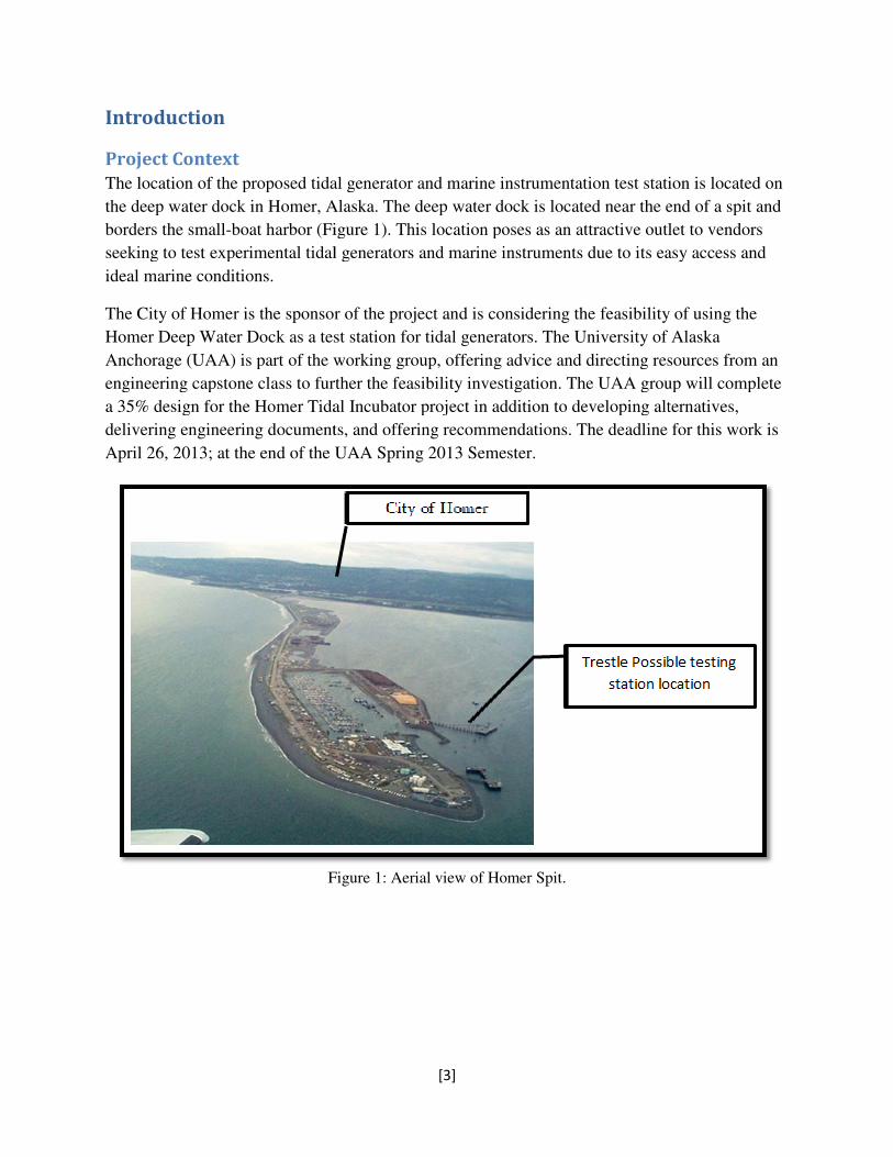
The location of the proposed tidal generator and marine instrumentation test station is located on
the deep water dock in Homer, Alaska. The deep water dock is located near the end of a spit and
borders the small-boat harbor (Figure 1
seeking to test experimental tidal generators and marine instruments due to its easy access and
ideal marine conditions.
The City of Homer is the sponsor of the project and is
Homer Deep Water Dock as a test station for tidal
Anchorage (UAA) is part of the working group, offering advice and directing resources from an
engineering capstone class to fur
a 35% design for the Homer Tidal Incubator project in addition to developing alternatives,
delivering engineering documents, and offering recommendations. The deadline for this work is
April 26, 2013; at the end of the UAA Spring 2013 Semester.
Figure 1: Aerial view of Homer Spit.
[3]
The location of the proposed tidal generator and marine instrumentation test station is located on
the deep water dock in Homer, Alaska. The deep water dock is located near the end of a spit and
Figure 1). This location poses as an attractive outlet to vendors
seeking to test experimental tidal generators and marine instruments due to its easy access and
The City of Homer is the sponsor of the project and is considering the feasibility of using the
Homer Deep Water Dock as a test station for tidal generators. The University of Alaska
Anchorage (UAA) is part of the working group, offering advice and directing resources from an
engineering capstone class to further the feasibility investigation. The UAA group will complete
a 35% design for the Homer Tidal Incubator project in addition to developing alternatives,
delivering engineering documents, and offering recommendations. The deadline for this work is
6, 2013; at the end of the UAA Spring 2013 Semester.
Figure 1: Aerial view of Homer Spit.
The location of the proposed tidal generator and marine instrumentation test station is located on
the deep water dock in Homer, Alaska. The deep water dock is located near the end of a spit and
This location poses as an attractive outlet to vendors
seeking to test experimental tidal generators and marine instruments due to its easy access and
the feasibility of using the
. The University of Alaska
Anchorage (UAA) is part of the working group, offering advice and directing resources from an
ther the feasibility investigation. The UAA group will complete
a 35% design for the Homer Tidal Incubator project in addition to developing alternatives,
delivering engineering documents, and offering recommendations. The deadline for this work is
Scope and Schedule
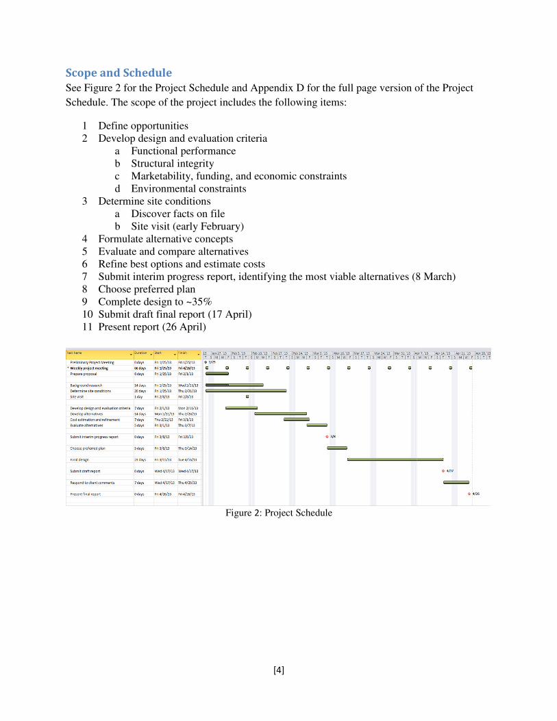
See Figure 2 for the Project Schedule and Appendix D for the full page version of the Project
Schedule. The scope of the project includes the fo
1 Define opportunities
2 Develop design and evaluation criteria
a Functional performance
b Structural integrity
c Marketability, funding, and economic constraints
d Environmental constraints
3 Determine site conditions
a Discover facts on file
b Site visit (early February)
4 Formulate alternative concepts
5 Evaluate and compare alternatives
6 Refine best options and estimate costs
7 Submit interim progress report, identifying the most viable alternatives (8 March)
8 Choose preferred plan
9 Complete design to ~35%
10 Submit draft final report (17 April)
11 Present report (26 April)
[4]
for the Project Schedule and Appendix D for the full page version of the Project
Schedule. The scope of the project includes the following items:
Develop design and evaluation criteria
Functional performance
Structural integrity
Marketability, funding, and economic constraints
Environmental constraints
Determine site conditions
Discover facts on file
early February)
Formulate alternative concepts
Evaluate and compare alternatives
Refine best options and estimate costs
Submit interim progress report, identifying the most viable alternatives (8 March)
Complete design to ~35%
draft final report (17 April)
Figure 2: Project Schedule
for the Project Schedule and Appendix D for the full page version of the Project
Submit interim progress report, identifying the most viable alternatives (8 March)
Organization
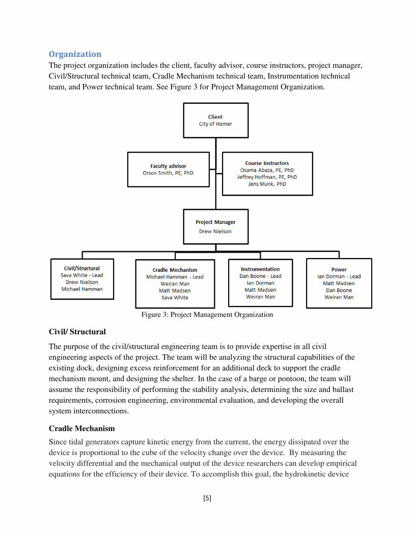
The project organization includes the client, faculty advisor, course instructors, project manager,
Civil/Structural technical team, Cradle Mechanism techni
team, and Power technical team. See Figure
Figure
Civil/ Structural
The purpose of the civil/structural engineering team is to provide expertise
engineering aspects of the project. The team will be analyzing the structural capabilities of the
existing dock, designing excess reinforcement for an additional deck to support the cradle
mechanism mount, and designing the shelter. In the ca
assume the responsibility of performing the stability analysis, determining the size and ballast
requirements, corrosion engineering, environmental evaluation, and developing the overall
system interconnections.
Cradle Mechanism
Since tidal generators capture kinetic energy from the current, the
device is proportional to the cube of the velocity change over the device.
velocity differential and the mechanical output of the
equations for the efficiency of their device. To accomplish this goal, the hydrokinetic device
[5]
The project organization includes the client, faculty advisor, course instructors, project manager,
Civil/Structural technical team, Cradle Mechanism technical team, Instrumentation technical
team, and Power technical team. See Figure 3 for Project Management Organization.
Figure 3: Project Management Organization
The purpose of the civil/structural engineering team is to provide expertise in all civil
engineering aspects of the project. The team will be analyzing the structural capabilities of the
existing dock, designing excess reinforcement for an additional deck to support the cradle
mechanism mount, and designing the shelter. In the case of a barge or pontoon, the team will
assume the responsibility of performing the stability analysis, determining the size and ballast
requirements, corrosion engineering, environmental evaluation, and developing the overall
capture kinetic energy from the current, the energy dissipated over the
to the cube of the velocity change over the device. By measuring the
velocity differential and the mechanical output of the device researchers can develop empirical
equations for the efficiency of their device. To accomplish this goal, the hydrokinetic device
The project organization includes the client, faculty advisor, course instructors, project manager,
cal team, Instrumentation technical
for Project Management Organization.
in all civil
engineering aspects of the project. The team will be analyzing the structural capabilities of the
existing dock, designing excess reinforcement for an additional deck to support the cradle
se of a barge or pontoon, the team will
assume the responsibility of performing the stability analysis, determining the size and ballast
requirements, corrosion engineering, environmental evaluation, and developing the overall
dissipated over the
By measuring the
device researchers can develop empirical
equations for the efficiency of their device. To accomplish this goal, the hydrokinetic device

[6]
must conveniently be placed and retracted from the flow for monitoring and maintenance
procedures. This not only implies the design of adequate mechanical devices for vertical mobility,
but also the structural stability of the mounting system in order to withstand drag loads on the
system.
Instrumentation
When testing a prototype tidal generator at any location, three primary areas of operation should
be monitored. First, the performance of the tidal generator, including power output and
efficiency, is monitored in order to determine the electrical power generation viability of the tidal
generator. Second, measurements are made of how well the tidal generator endures within the
testing environment. Lastly, the effect of the tidal generator on the surrounding environment is
also observed. The above measurements are made using a system of instrumentation consisting
of a series of strategically placed instruments, a data collection and storage device, a user
interface computer with software able to display and control the various instruments, and a data
transmission system. Additionally, some aspects of generator durability may be made using
direct visual observation of the tidal generator itself. For further discussion of tidal generator
and site monitoring, refer to Appendix C.
Power
The power generated by the tidal generators will need to be safely dissipated or be stored. This
will be accomplished by the use of a load bank with a possibility of an electrical interconnection
to the HEA utility grid.
All options detailed within this report will require the use of a load bank. The load bank not only
dissipates the energy but can simulate different load conditions. Thus the customer will be able
to subject their prototype design to numerous simulated conditions.
An electrical interconnection is not necessary for the overall success of the project but can offer a
novel amenity to the proposed facility.
Of the alternatives listed in this report the dock mounted option will accommodate the largest
range of tidal generators and is the only alternative that will accommodate an interconnection
with the utility. However these advantages may not be important to the market, especially when
one considers that the floating option can accommodate small scale prototypes just as well if not
better than the dock mounting alternatives.
The interconnection and wiring methods are governed by various standards and guides. An
overview of these publications can be found in Appendix B.

[7]
Hydrokinetic Overview
Hydrokinetic devices have long been employed to improve the quality of life. In modern times
we have gone from the simple watermill for rude industrial purposes to the great dames of the
past century. Today with high energy prices interest has grown in the development and
utilization of small scale hydrokinetic devices to offset the reliance on high price oil or natural
gas. These devices are characterized by low power generation, which is due to low hydraulic
head and current technology. These devices are referred to as unconventional systems (Khan,
Bhuyan, Iqbal & Quaicoe, 2009). The demand for alternate sources of electric power generation
and available hydro resource has drawn researcher and developers (R/D) to pursue further
hydrokinetic development.
On the numbers of R/Ds currently working on the development of hydrokinetic devices one
research group reported 76 R/Ds surveyed (Khan, Bhuyan, Iqbal & Quaicoe, 2009). This is in no
case on exhaustive list; however, it does show the current efforts being placed into bringing this
technology forward. This interest is important since technological advancement is needed in
some areas to make unconventional generation possible (Johnson, 2010).
The positioning of Alaska is promising in reference to hydrokinetic energy potential. Alaska has
40% and 90% of U.S. river energy and tidal energy resources (Johnson, 2010). To put this in
perspective, this amounts to 1,250 TWh/yr for southern Alaska.
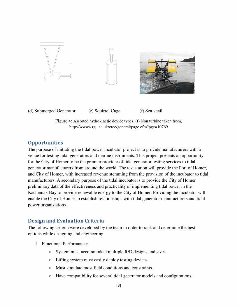
Currently there are multiple hydrokinetic device designs under R/D, Figure 4 shows several
turbine variations and one non turbine (f) of the Sea-snail design. The turbine types (a)-(e)
employ drag or lift forces on their blades for power generation and Sea-snail (f) employs drag
forces on the hydrofoils (Khan, Bhuyan, Iqbal & Quaicoe, 2009). Other designs exist however
for brevities’ sake only designs specific to Figure 4 represented. This is not to say that other
designs would not be compatible with testing station this project and report is exploring. The
orientations of many designs can be accommodated and accurately tested in a slightly different
geometric orientation. For example the rigid mooring can be tested upside down from its design
orientation.
(a) Inclined Axis (b) Rigid Mooring (c) Non-submerged Generator
[8]
(d) Submerged Generator (e) Squirrel Cage (f) Sea-snail
Figure 4: Assorted hydrokinetic device types. (f) Non turbine taken from,
http://www4.rgu.ac.uk/cree/general/page.cfm?pge=10769
Opportunities
The purpose of initiating the tidal power incubator project is to provide manufacturers with a
venue for testing tidal generators and marine instruments. This project presents an opportunity
for the City of Homer to be the premier provider of tidal generator testing services to tidal
generator manufacturers from around the world. The test station will provide the Port of Homer,
and City of Homer, with increased revenue stemming from the provision of the incubator to tidal
manufacturers. A secondary purpose of the tidal incubator is to provide the City of Homer
preliminary data of the effectiveness and practicality of implementing tidal power in the
Kachemak Bay to provide renewable energy to the City of Homer. Providing the incubator will
enable the City of Homer to establish relationships with tidal generator manufacturers and tidal
power organizations.
Design and Evaluation Criteria
The following criteria were developed by the team in order to rank and determine the best
options while designing and engineering.
1 Functional Performance:
○ System must accommodate multiple R/D designs and sizes.
○ Lifting system must easily deploy testing devices.
○ Must simulate most field conditions and constraints.
○ Have compatibility for several tidal generator models and configurations.

[9]
○ Safely dissipate generated energy.
○ Must be able to monitor tidal generator performance.
2 Structural Stability:
○ Must withstand vertical and horizontal dynamic and static loading in conjunction
with corrosion, fatigue, and fracture fail modes.
○ Must provide for protection of instrumentation and data collection devices.
3 Economical Profitability:
○ Operation and Installation costs must be minimized as not to exceed R/D revenue
constraints.
4 Environmentally Safe:
○ Power Generation fuel and mechanical system hydraulic fluid must be able to be
reasonably contained against possible pollution.
○ Hydrokinetic devices must not adversely affect the marine life surrounding the
teststation.
○ Must be able to monitor environmental conditions at the site.
Site Conditions
On February 22, 2013, the UAA Tidal Energy Incubator Project design team accompanied by Dr.
Orson Smith traveled to Homer, Alaska to perform a site visit and discuss various issues and
ideas with members of the Homer community. Upon arrival in Homer, the design team met with
Community and Economic Development Coordinator, Katie Koester, Port
Director/Harbormaster, Bryan Hawkins and Public Works Director, Carey Meyer. At this
meeting, Mr. Hawkins provided the team with a brief history of the harbor and its current
mission in serving the City of Homer. Mr. Hawkins reiterated that both sides of the Homer Deep
Water Dock would be unavailable for use as potential locations for the tidal generator incubator
project as these areas are used to moor vessels. Mr. Hawkins indicated that two large beams left
over from the wood chip conveyor system currently extend from the dock roadway adjacent to,
but not attached to the deep water dock. These two beams would be in a prime location to site
the tidal generator project as they are located along the dock roadway furthest from the shore and
above the deepest available water, as well as on the correct side of the roadway to receive the
incoming tidal stream with little interference from the roadway piles. Mr. Hawkins also told the
team that the tide at the deep water dock flowed in the same direction - roughly southeast - for
both incoming and outgoing tides. Mr. Hawkins also provided the team with the available as-
built structural and electrical documents for the deep water dock and dock roadway. These
documents were photographed by team members as necessary.
[10]
Following this discussion, the design team split into two groups to view the deep water dock and
roadway from above and below. Mr. Hawkins and Mr. Meyer escorted one of the groups onto
the dock roadway to give team members a top side view of potential project site locations. Team
members observed the two beams previously described by Mr. Hawkins as well as the
availability of utility services along the dock roadway. Team members also took pictures of the
deep water dock and roadway in order to maintain an accurate picture of the site details as the
design process moves forward. The second group was taken by Port Maintenance Supervisor,
Aaron Glidden in the harbormaster patrol vessel to observe the underside of the dock roadway
from sea level. During this aspect of the site visit, the dock piles were closely examined, the
undersides of the two beams were observed, and the northwest face of the dock roadway was
looked over for potential advantages and disadvantages related to designing the tidal generator
project. Additional pictures were also taken. The groups then switched places to allow each
group a complete view of the site potential.
Upon returning from the visit to the deep water dock, the team met with Homer Electric
Association (HEA) Engineer, Mike Tracy. Mr. Tracy indicated that connecting the prototype
tidal generators to the HEA electrical grid through an intertie would likely not pose any problems
for HEA.
At 1:00 p.m., the UAA design team met with the Homer Tidal Energy Incubator Working Group
and other community members at Homer City Hall. The design team gave a brief presentation to
the working group outlining the project in its current state. The presentation consisted of the
organizational structure of the design team, a timeline of how the team planned to move forward
with the project including a list of deliverables for the working group, and various design
possibilities for the tidal energy incubator project. Following the presentation, a general
discussion of the project took place between the working group and team members. At this time,
Kachemak Bay Research Reserve Manager, Terry Thompson offered to provide the team with
any data his organization had available concerning the conditions at the potential project site.
Additionally, Public Works Director, Carey Meyer offered to provide structural and loading
information about the deep water dock and dock roadway.
During the site visit, the team assessed the existing electrical equipment. The current electrical
service to the dock is fed by a 24.9Y/14.4 kV primary to 480Y/277V secondary 150VA rated
padmount transformer feeding a 600A rated switchboard NEMA 4X/3R type. This switchboard
is the main distribution panel and named ‘MDS’. Both the transformer and MDS are located at
shore. The MDS provides power to the dock via a 225A rated circuit breaker feeding a two inch
rigid metal conduit with four #4/0 AWG XHHW conductors. This conduit is routed on the north
side of the trestle. These conductors land on the line side terminals of another switchboard rated
for 400A named ‘DS’. This switchboard is located on the dock itself and provides the power for
all loads on the dock and the heat trace for the main water pipe serving the dock.

[11]
Alternative Concepts
The design team held several meetings where alternative concepts were formulated. The initial
concept was a facility placed somewhere on the deep water dock. Much of the space along the
dock was eliminated in consultation with the Harbormaster and Public Works Director. The end
of the dock was eliminated because it is still in use for mooring large vessels, and the shallower
end of the trestle was eliminated because the water needs to be deep enough to accommodate the
prototype tidal generator. During the team’s site visit, two beams that protrude out near the end
of the trestle were pointed out by the Harbormaster (Figure 5), and have been selected as the
most practical location for the testing facility on the dock.
The design team also formulated the concept of having a floating facility that could be moored at
the dock so testing could take place either at the dock or at some other location. The team
formulated two alternatives for this concept. Either the facility could be built on a large barge
that would be more seaworthy, or it could be built on a smaller pontoon barge that would be
more mobile.
The alternative concepts are summarized below:
● A permanent facility built at the deep water dock on the two beams protruding out near
the end of the trestle.
● A floating facility built on a large barge
● A floating facility build on a smaller, more mobile pontoon barge
Alternatives Analysis
The following section discusses the remaining alternatives that were deemed practical by the
constraints of the project.
Alternative 1 - Dock Mounted
The structural support for the trestle mounted cradle system and the instrumentation and system
auxiliary equipment housing would be placed on the empty beam sections presented in Figure 5
below. These beams are left over from the wood chip exportation project where the conveyor
belt loading system rested.
A setupsuch as a rack and pinion system as depicted in Figure A1 (see Appendix A) could be
used to deploy the testing devices. The system would be equipped with instrumentation and
sensors to sense the changing tides. This will allow the system to automatically raise and lower
the cradle system in sequence with the tide. The option of deploying the system at a set distance
above the bay floor would also be included.

[12]
Figure 5: Dock extension from the sawdust operation. These unused beams would ideal for the location of
a Hydro Test Station to be mounted on the trestle.
Advantages
Revenue: An advantage of attaching the cradle mechanism to the dock is that the revenue
generated will be confined to the City of Homer. Researchers who desire to test their devices in
the unique conditions of Kachemak Bay can be charged for the time they take to complete their
experiments and for the use of the site location that is within Homer’s jurisdiction. By attaching
the cradle to the dock, the city of Homer could potentially add new employment options for its
citizens. The mechanism itself will require maintenance and repairs, both of which can be done
by Homer businesses or by the City of Homer.
Interconnection compatibility: A dock mounted system allows for interconnection of the tidal
generator output to the city of Homer’s electrical grid system. The customer’s prototypes could
be allowed to run for a period of several months. This free electrical energy is a minor benefit to
HEA. The real appeal of a grid interconnection to the project is that it gives the customer a proof
of design capability. If a tidal generator was left in place for an extended duration, the power
generated could potentially be used for supplementing power to the ice plant.
Wider range of generators could be tested: The Dock Mounted option could be designed in such
a way to allow for larger kW rated tidal generators than the floating options. This is in part due
to the fact the dock has a much larger weight limits than the other alternatives. This allows for
the installation of a larger load bank. The only variable limiting the type of tidal generator to be

[13]
installed is that tidal generator’s physical dimensions. Hypothetically, the dock option’s
electrical system could accommodate a 1-MW tidal generator.
Reuse of existing electrical components: The transformer for the dock is serving no other loads
and can therefore be utilized as an isolation transformer for the site. This means that the dock
mounted option can accommodate a tidal generator with a peak output of around 150 KW
without the need for installation of a new transformer. In addition, the main distribution panel is
rated for 600A which can accommodate a wide range of possible designs.
Enclosure options: The physical elements of the coastal and ocean environment dictate the
protection of instrumentation, data collection system, and the cradle mechanism system. The
unused beams of the dock offer simple accommodation by either employing a connex or a simple
frame structure. The enclosure would be similar to the existing building located on the trestle.
Secondary use as an ocean sensor test facility: Long-term monitoring of oceanographic
conditions is a mission of the Kachemak Bay Research Reserve, based in Homer. This NOAA-
funded monitoring would be an advantage to vendors of oceanographic instrumentation who
want to test new sensor systems in comparison to well-maintained systems operated by the
Reserve. The features that would accommodate monitoring of conditions and performance of
tidal generators are compatible with this secondary use of a test station fixed at the Deep Water
Dock.
Available structure for mounting instruments: The in-place dock structure provides additional
options when deciding upon instrument placement and orientation. These additional placement
options may allow for better monitoring of site conditions, environmental impact, and generator
performance than would be reasonably available with the mobile floating test site option.
Available electrical power: Reliable power is accessible from the Homer Electric Association
grid to provide electricity for the facility and instrumentation system.
Long term monitoring of site conditions: Instruments can be put in place on a permanent or
semi-permanent basis, allowing for long term monitoring of the site conditions. This monitoring
will take place during tidal generator testing, but can also be performed separate from a tidal
generator test in order to increase the baseline data available for the test site. This additional
baseline data may be a positive marketing characteristic for potential clients.
Protected location with known site conditions: The project site next to the deep water dock is in
a protected location with known environmental conditions. Thus, choosing appropriate
instruments and calibrating them for these conditions will be easier than doing the same for the
changing environmental conditions found with the floating test site option.
Adding further instruments: If a client or the City of Homer deems it necessary to enhance the
existing instrumentation system, placing additional instruments at the test site would be
[14]
relatively straightforward. Additional power would be readily available, and the existing dock
structure along with the deployed instrumentation system would allow for an uncomplicated
deployment of further instruments.
Data collection, storage, and transmission: The permanent and land based nature of the project
location at the dock allows data generated by the instrumentation system to be collected, stored
and analyzed in a protected and in an easily accessible environment. A client would have the
ability to observe the testing data in real time as it is being collected and analyzed by the
instrumentation computer in the sheltered laboratory. The client could also extract data for
further transmission or analysis at any time. Additionally, if further transmission of data is
required by a client, internet access at the dock site is readily available.
Site conditions: One of the benefits for researchers in testing their designs in application type
conditions is for design flaws and weaknesses to be analyzed. This permits the researcher to alter
the design until satisfactory test results are obtained; saving capital that would have been lost if
the flawed design had been marketed. In order for testing facilities to attract researchers they
must simulate actual operating conditions. In tidal power generation the velocity, direction, and
sediment content of tidal currents is of crucial importance. Since Kachemak Bay has a significant
silt content and seasonal presence of frazil and brash ice it is not a mitigating decision factor in
the stationary and mobile test station options. The above variable conditions are ideal for testing
devices in a real world environment.
Disadvantages
Moderateand unidirectional current:The location of the Deep Water Dock produces a
unidirectional flow with a peak mid-tidevelocity of around two knots. Two knots (one meter per
second) is generally considered the minimum current velocity necessary for testing hydrokinetic
devices (Johnson, 2010). The low velocity current with the dock mounted option leaves
uncertainty as to whether or not significant interest in testing devices at the dock is realistic. On
the other hand, rural coastal communities that install micro-hydropower systems of 100kW or
less to supplement other power generation mechanisms may be well-represented by the
conditions at the Deep Water Dock.
Higher freeboard: Kachemak Bay has a tidal range of approximately 18 ft. This relatively large
tide range makes the Bay an attractive place to test tidal power turbines and also presents
additional difficulties in the design of the mounting system for testing devices. The testing
devices must be kept beneath the trough of the waves, and preferably at a consistent relative
position to either the water surface (floating systems) or the seabed (bottom-mounted systems).
Testing floating systems requires that the mounting system be capable of fluctuating with the tide
change. In addition to this challenge, the full extension of the cradle mechanism for yearly low
tides requires a larger system to accommodate the reach. Also, it requires systems to be
significantly stronger to withstand the high stresses created by the large tidal moment on the
system.

[15]
Instrumentation maintenance: Permanently deployed instruments would require significant effort
to calibrate and replace. Some instruments may be placed underwater either at the dock or some
distance away. These instruments would be less accessible for maintenance than the equivalent
instruments in a floating test site system.
Alternative 2 - Floating
This is a major alternative with two variations: flat-deck barge and pontoon barge. Both could be
kept afloat and be moored at the Dock for testing there or moved to a location with stronger tidal
currents or other conditions different from those at the Dock. The pontoon variation might even
be designed for disassembly and transport by truck for use at a river site.
A floating system based at the dock would have a cradle mechanism and instrumentation housing
implemented on a watercraft that could be towed to other locations. The cradle mechanism on
the floating option would keep the test tidal generators at a consistent depth below the waterline
as the craft’s vertical position relative to the water would not change.
Advantages
Use of trestle electrical interconnection system at Homer only: By implementing a marine
electrical connection system the floating option could utilize the interconnection to the Homer
power grid allowing for the respective inherent benefits of the dock mounted option. However,
this benefit would be restricted to the vicinity of the deep water dock, and limited by the length
of the marine electrical connection system.
Transportation: To accommodate additional research conditions and locations, the floating
designs would be capable of sea transportation.
Instrumentation access: Periodically instrumentation needs to be calibrated and repaired or
replaced. Because the floating design options will require a method of readily deploying and
retrieving the in-water instrumentation, required maintenance will be easier to perform.
Disadvantages
Generator system required: Due to the remote nature of the floating options, portable electrical
generation will be required. Most likely this will be accomplished with a fuel powered generator.
Electrical power is necessary to run the monitoring devices for the testing system and testing
equipment for the proposed testing facility. Both floating options would only be able to utilize
HEA power at the Deep Water Dock, and would require an onboard power generation system.
For the addition of the generator system, fuel transportation and explosion prevention design
considerations must be made.
Anchoring system: To properly and safely anchor a barge so that operations and testing of
equipment may begin, the barge must be both stable and able to retain a specific position and
orientation as determined by the needs of the tester. Anchoring systems for barges vary only

[16]
slightly from well-established anchoring systems for small boats. If a barge were to be anchored
in the traditional single anchor method, the position and direction would be set by the currents
and wind. With the layout and orientation restraints of the cradle mechanism, the preferred
method of anchoring would be to either use a two-anchor method or four-anchor method.
Unknown site conditions: Whenever the floating option is taken to perform testing at a new
location the site conditions will only be known to a small extent. Repeated testing at one site,
such as the deep water dock, will build up a collection of site condition data. This data would
enable the clients to know exactly what conditions their prototype tidal generator will encounter.
Of course the floating option could be taken to the same locations repeatedly, but site condition
data taken at a few sites will be less accurate than repeated testing at just one site.
Deploying/retrieving instruments: Just as the floating option has an advantage in being able to
readily deploy and retrieve instruments, it also has some disadvantages. Every time the floating
facility is moved, the instruments will need to be retrieved, stored, and then deployed at the new
site. The instruments could remain in place at a permanent facility, only needing to be moved
when necessary. Retrieving and deploying instruments also entails attaching some mechanism to
the floating facility to do the work, which adds complexity to the design.
Data storage/collection: Data collected by the instrumentation will need to be stored and
retrieved by the clients. This system is a challenge because the data will either need to be stored
while the test is taking place and later retrieved or transmitted from the floating facility to an on-
shore computer. If the data is to be retrieved it would entail either the client visiting the floating
facility at regular intervals to download the data, or downloading it after the test is complete.
There may be issues with this method because while the facility is out at sea, a problem could
occur with the test that would render the data unusable. Transmitting the data from the facility
presents a large design challenge, and would require access to a network of some type that may
not be available throughout the Cook Inlet.
Long term testing: The client may want to test their prototype tidal generator over an entire lunar
cycle to expose it to a variety of tidal conditions. This presents a challenge for the floating option
because it will need to remain at sea and anchored in place through a large range of weather and
sea conditions. If the conditions get too bad a long term test may need to be aborted in order to
protect the vessel and tidal generator from being damaged.
Barge
A typical flat deck ocean barge would be retrofitted to secure an excavator for deploying
hydrokinetic devices and marine instrumentation. A connex retrofitted for housing
instrumentation and data collection and a marine grade generator with a fuel tank would be
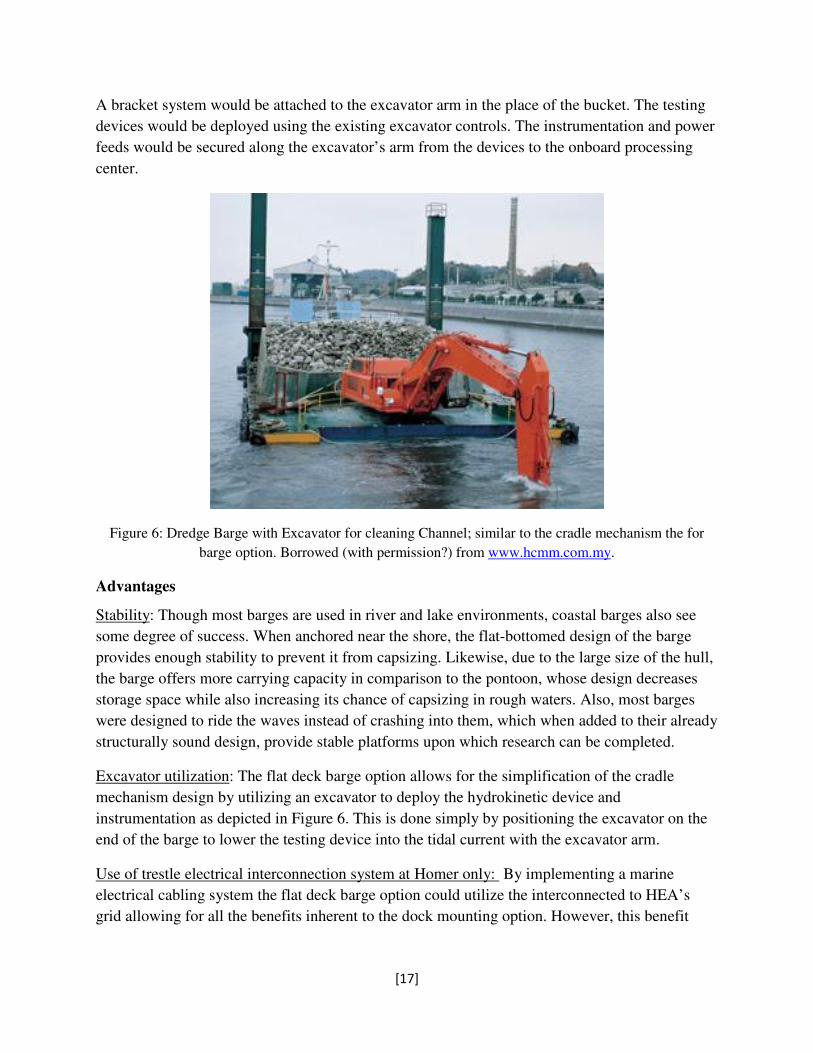
placed on the barge opposite from the excavator. The dredge barge in Figure 6 represents the
barge testing station with the placement of the instrumentation housing and power generation
system substituting the rock collection.
[17]
A bracket system would be attached to the excavator arm in the place of the bucket. The testing
devices would be deployed using the existing excavator controls. The instrumentation and power
feeds would be secured along the excavator’s arm from the devices to the onboard processing
center.
Figure 6: Dredge Barge with Excavator for cleaning Channel; similar to the cradle mechanism the for
barge option. Borrowed (with permission?) from www.hcmm.com.my.
Advantages
Stability: Though most barges are used in river and lake environments, coastal barges also see
some degree of success. When anchored near the shore, the flat-bottomed design of the barge
provides enough stability to prevent it from capsizing. Likewise, due to the large size of the hull,
the barge offers more carrying capacity in comparison to the pontoon, whose design decreases
storage space while also increasing its chance of capsizing in rough waters. Also, most barges
were designed to ride the waves instead of crashing into them, which when added to their already
structurally sound design, provide stable platforms upon which research can be completed.
Excavator utilization: The flat deck barge option allows for the simplification of the cradle
mechanism design by utilizing an excavator to deploy the hydrokinetic device and
instrumentation as depicted in Figure 6. This is done simply by positioning the excavator on the
end of the barge to lower the testing device into the tidal current with the excavator arm.
Use of trestle electrical interconnection system at Homer only: By implementing a marine
electrical cabling system the flat deck barge option could utilize the interconnected to HEA’s
grid allowing for all the benefits inherent to the dock mounting option. However, this benefit

[18]
would be restricted to the vicinity near the deep water dock and limited by the length of the
marine electrical cabling scheme.
Barge application flexibility: A barge outfitted with a cradle mechanism may serve a larger
purpose than just testing tidal generators. In the event that tidal generator manufacturers find the
incubator less popular than expected, the barge may be used for alternative purposes in areas of
academic research. Also, the flexibility of a barge to be used for various purposes allows
purchased used barges to be refitted for the purpose of the project.
Disadvantages
Barge availability: Though barges are common, it may be difficult to find the correct size and
type of barge for the project in Alaska. A seller for this type of barge could eventually be found
if a used barge is preferred. Transportation from another part of the world may be necessary to
obtain a barge, which would add a significant cost to the project in time and fuel. A larger barge
found locally would also be an extra expense and would also take up precious dock space as
large barges are usually not capable of effective grounding for storage purposes. Depending on
the size and availability of barges available for sale, a custom barge may have to be
commissioned. A custom barge would enable the team to design specific requirements for the
size and function. In any case, an existing barge can also be modified to meet the requirements of
the design.
Pontoon
The pontoon option would resemble a catamaran style flat deck barge with the center open to
allow for the deployment of the cradle system as depicted below in Figure 7. This pontoon would
be custom to meet the design constraints and objectives. The cradle system wouldbe mounted
directly over the void in deck and could resemble the rack and pinion system in FigureA1, see
Appendix A.

[19]
Figure 7: Model of pontoon testing setup.
Advantages
Symmetric loading: The separation of the pontoons in the catamaran design is convenient for the
implementation of the cradle mechanism for mounting the testing devices. The position of the
cradle mechanism and attached device in conjunction with the identical pontoons yields
symmetric loading. This system provides excellent stability and requires fewer complicated
design calculations.
Land transportation: In addition to being transported by sea, the pontoon could be designed to be
disassembled and trucked to river locations throughout the state on the road system for testing.
Disadvantages
Custom fabrication: Due to the uniqueness of the cradle mechanism application and the
weakness of aluminum, which pontoons are usually made out of, to galvanic corrosion in
seawater, a custom made pontoon would have to be ordered. The custom pontoon would be
made out of a strong, corrosion resistant material and would add to the capital expenditure.
Seaworthiness: In rough seas, pontoons are generally known to plow into the waves instead of
riding them due to their design. This instability could prove to be problematic, as the increasing
frequency of rough waves could damage the pontoon.
Spatial weight challenges: The placement of fuel and the generator creates potential spatial
weight challenges with meeting the size limitations of a river testing operation. These spatial
weight challenges may also be detrimental to the general stability of the craft.

[20]
Conclusion
This report shows that the vision of developing a Tidal Generator and Marine Testing Station can
be realized through either a dock mounted system or two alternative floating mounted systems.
For the dock mounted option, the cradle system would be deployed from the trestle of the Deep
Water Dock and into the tidal flow. The cradle system would mechanically raise and lower to
counter the fluctuation of the tides. An instrumentation system for monitoring the performance of
the tidal generator and the marine environment conditions would be deployed with the cradle
system and in the surrounding environment.
The barge and pontoon designs’ cradle system would be less complicated since there is no need
to counter the tidal fluctuation. However, factors such as the vessel design and material used
must be considered to prevent capsizing or structural fail. A method for deploying the
instruments and retrieving collected data would also have to be developed.
Considerations must also be made to the economic factors that surround the project. For the
barge or pontoon option, factors like transportation fees and the cost to build could sway the
project towards being unprofitable. Likewise, the close proximity of the dock mounted option to
Homer’s port and with no need to buy or construct a floating platform when an existing one can
be used could be an economically viable method moving forward.
Based on the advantages and disadvantages of each option presented in this report, the Homer
Tidal Energy Incubator Group will need to select one alternative for further development in the
next phase of the project.
[21]
Appendix A - Cradle System
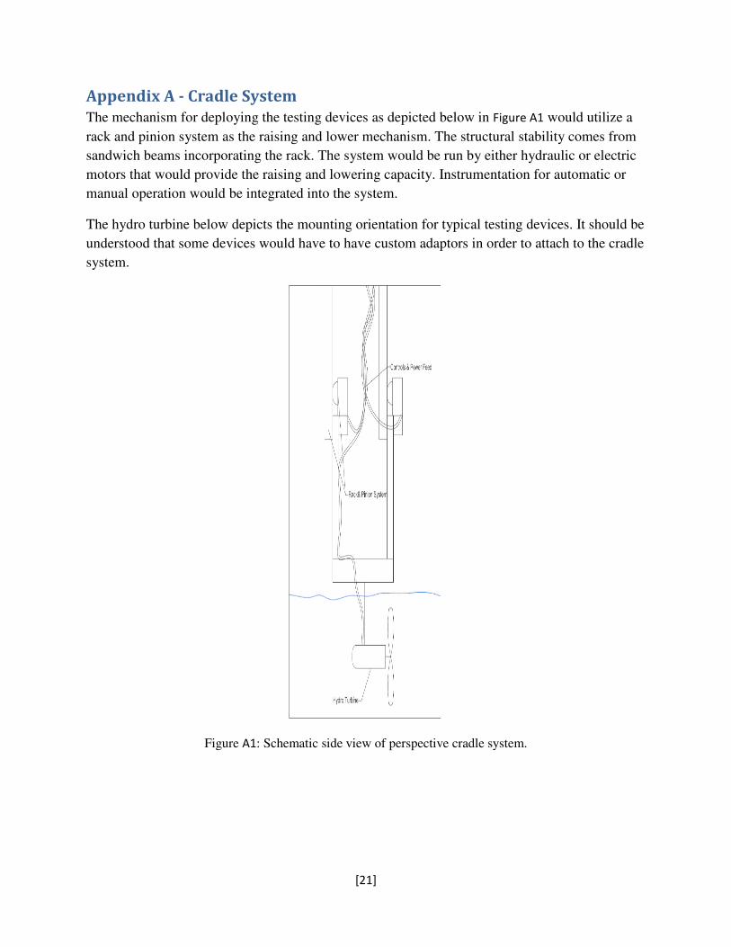
The mechanism for deploying the testing devices as depicted below in Figure A1 would utilize a
rack and pinion system as the raising and lower mechanism. The structural stability comes from
sandwich beams incorporating the rack. The system would be run by either hydraulic or electric
motors that would provide the raising and lowering capacity. Instrumentation for automatic or
manual operation would be integrated into the system.
The hydro turbine below depicts the mounting orientation for typical testing devices. It should be
understood that some devices would have to have custom adaptors in order to attach to the cradle
system.
Figure A1: Schematic side view of perspective cradle system.

[22]
Appendix B - Literature Review
The most important literature governing interconnection to utility power for this project is
Homer Electric Association’s (HEA) “Electric Service Requirements (Service Assembly Guide)
2009” (HEA, 2009) and “Requirements For The Interconnection of Member-Owned Alternative
Power Installations” (HEA, n.d.). The latter is a summation of the applicable standards found in
the former and in HEA’s Current Tariff (HEA, n.d.). These standards are in turn derivative of
Institute of Electrical and Electronics Engineers standards 1547. This standard lays out the
“...minimum functional technical requirements...” (IEEE, 2003, p. iv) rather than a design guide.
The standard seeks to be technology neutral in its requirements. The IEEE does provide a guide
to the IEEE 1547, the IEEE 1547.2, which provides clarification, explanation and justification
for the standards described in IEEE 1547 (IEEE, 2008). Also, its appendix contains some
example designs that meet the requirements.
The IEEE publishes two more additional design guides for interconnections. IEEE 1547.3 is
meant to “...help implement optional approaches for monitoring information exchange, and
control” (IEEE, 2007, p. iv) between the alternative energy source and the utility grid. IEEE
1547.4 covers good design, operation and integration practices connecting and or disconnecting
the alternative energy source for the local utility without disturbing the local grid or power on the
facility site (IEEE, 2011).
If and when the interconnection is installed, it is required by HEA to be tested, prior to being
energized, in accordance with IEEE 1547.1 (IEEE, 2005). The IEEE 1547.1 “… provides
conformance test procedures to establish and verify compliance with the requirements of IEEE
1547” (IEEE, 2005, p. iii) but does not define specific measurement techniques, those are
outlined in other technical publications.
In addition HEA requires that converter/inverter required for the interconnection meet the
minimum requirements described in Underwriters’ Laboratory Standard 1741 (UL, 1999) and the
recommendations in IEEE 519 (IEEE, 1992).
IEEE 1159 (IEEE, 2009) presents useful guidelines and recommendations for power quality
monitoring and it ”…discusses the selection of appropriate measuring instruments, limitations of
these instruments, application techniques, and the interpretation of monitoring results.” (p. iv).
The IEEE has also published recommendations for transferring that data in IEEE standard 1159.3,
and outlines useful tips for the encoding and decode of software files containing power quality
data (IEEE, 1992).
Any land based alternative’s electrical installations by Alaska Statutes 18.60.580 shall adhere to
the National Electrical Code 2011 (NFPA, 2011) on the secondary side of the site transformer
and the National Electrical Safety Code 2012 (NFPA, 2012) on the primary side of the site
transformer.
Wiring methods implemented for the installation of electrical components will be appropriate for
corrosive and wet conditions as illustrated in UL standards 1309 (UL, 2011).

[23]
Appendix C - Instrumentation and Environmental Monitoring
The strategy for monitoring the effects of the tidal generator on the surrounding environment
consists of measuring several ocean properties both before and after interaction with the tidal
generator. Measuring the effect of the tidal generator on the surrounding environment is
necessary for environmental permitting purposes as well as fully understanding the performance
and efficiency of the tidal generator.
The environmental properties that should be monitored are:
● Water velocity – the overall movement of the water
● Water turbulence – small variations in the overall movement of the water
● Water depth at the test site
● Water temperature
● Water conductivity - used to determine water salinity
● Water turbidity – the cloudiness of the water
● Size of particulates suspended in the water
● Scouring of the seafloor beneath the hydrokinetic device
● Noise produced by the hydrokinetic device
● Cetacean activity near the test site
● Other wildlife activity near the test site
● Capability to extract water samples for further laboratory testing
“The energy flux contained in a fluid stream is directly dependent on the density of the fluid,
cross-sectional area, and fluid velocity cubed” (Khan, 1824). Thus, the water velocity contains
the majority of the energy in a tidal stream. Measuring the water velocity over the entirety of the
affected water column both upstream and downstream of the generator is of high importance.
“Acoustic Doppler Current Profiler (ADCP) instruments are used to measure the speed of water
across an entire water column” (Hydro International, 1).
Water turbulence is important to measure in order to understand the small variations in water
movement that occur at the test site naturally as well as those resulting from tidal generator
activity. Water turbulence can adversely affect a tidal generator as inconsistent water flow can
reduce power output efficiency and increase generator deterioration. An instrument commonly
used to monitor water turbulence is called the Acoustic Doppler Velocimeter (ADV).
“Velocimeters belong to a special class of high-resolution 3D instruments used to study rapid
velocity fluctuations in the laboratory or in the ocean. These instruments have three or more
focused beams to measure with high sampling rates in a small point” (Nortek AS, 2013). Use of
multiple ADV devices will likely be necessary for accurate monitoring of the test site.
Water conductivity, temperature and depth are typically monitored using a device called a CTD.
“The device’s primary function is to detect how the conductivity and temperature of the water
column changes relative to depth. Conductivity and temperature information is valuable because
[24]
the salinity (the concentration of salt) of the seawater can be derived from these two variables”
(Ocean Explorer, 1). The salinity of the seawater contributes to its overall density. As stated
above, the energy present in a tidal stream is dependent on the water density (Khan, 1824), thus
measuring this quantity is important for determining the efficiency of the tidal generator.
The measurement of turbidity, or the amount of sediment suspended within the water, is crucial
when monitoring a tidal generator test site. High sediment levels may cause significant wear on
a tidal generator. Test site clients will want accurate turbidity data to compare with the
deterioration observed on the tested tidal generator. Optical backscatter sensors (OBS) “measure
the amount of light transmission of water to give a measurement of the suspended solids in that
water” (Campbell Scientific, 2013). An optical backscatter sensor coupled with water sampling
will provide sufficient suspended sediment data for the test site.
A tidal generator that causes significant changes to water flow can cause scouring of the seafloor
in a shallow ocean environment. This seafloor scouring can affect sea life present on the ocean
floor beneath the tidal generator, and over the long term, change the floor contour. A simple
underwater camera with appropriate lighting appears to be the most reasonable and cost effective
method for observing seafloor scouring.
A tidal generator consists of moving parts which may generate sounds audible to local cetaceans
- primarily beluga whales. Due to the protected status of Cook Inlet beluga whales,
environmental permitting will not allow any significant disruption to the whale’s behavior. Thus,
any tidal generator tested in Cook Inlet cannot produce noise which is disturbing to beluga
whales. The use of a hydrophone (underwater microphone) tuned to appropriate frequency range
can monitor the tidal generator’s audible noise output. This hydrophone can also be used
observe the behavior of beluga whales as they travel near the tidal generator site.
Surveillance of other sea life at the tidal generator site may also be desirable. Salmon returning
to the Homer Spit ‘Fishing Hole’ pass near the tidal generator site each spring and summer.
Observing these salmon as they pass near and interact with the test tidal generator is most
effectively accomplished with the underwater camera which is already in place to view the
behavior of the tidal generator itself.
Tidal generator incubator clients may want the ability to perform further testing on the seawater
at the test location. Having the means to extract water samples at the tidal generator site, as well
as upstream and downstream of the tidal generator will allow clients to collect water samples to
be analyzed by an outside laboratory.

[25]
Generator monitoring instrumentation
For monitoring the electrical generation capabilities and the environments effect on the tidal
generator the team has identified the following measurements:
1 Rotation speed
2 Tidal generator vibrations
3 Strain on tidal generator components
4 Electrical Characteristics (voltage, current, power)
5 Power quality monitoring
6 Tidal generator loading
7 Visual inspection of the tidal generator
A measure of the tidal generators rotation speed is necessary so the tidal generators response to
the water velocity under a variety of loading conditions can be characterized. The client will also
need to know how much power the tidal generator is outputting based on its rotation speed.
As the prototype tidal generator operates under a variety of environmental conditions it will
experience strain on its components and vibrations. Over time the strain and vibrations will
cause wear on the prototype tidal generator. The capacity to monitor the strain and vibrations,
along with the conditions that caused them, will allow the client to gain a better understanding of
what will be required to limit them. The client may or may not have an instrument for measuring
strain and vibration installed on their tidal generator, so providing them for use is necessary.
Typical instruments for measuring strain are strain gauges, and accelerometers are used to
measure vibration.
Monitoring the electrical characteristics of the prototype tidal generator is essential for this
project. The clients who are performing the testing will need to know what voltage their tidal
generator is producing, what current it is producing, and what the power output is, all under a
variety of site conditions and electric loads. Providing the means to monitor the electrical
characteristics of the prototype tidal generator will allow the client to determine the overall
power quality produced by the device. These measurements are all importing for the clients in
determining their tidal generators performance. There are a large variety of instruments that can
be used to monitor the electrical characteristics of a tidal generator, such as the digital multimeter
and oscilloscope. Power quality monitoring will be implemented in accord with the IEEE
Recommended Practices for Power Quality Monitoring standard.
In order to adequately test the prototype tidal generator, the client will need to be able to control
the tidal generators loading. The client will need to be able to simulate a wide variety of loads in
order to thoroughly test the prototype tidal generator. The instrument required for controlled
loading is a load bank.

[26]
The client will need to be able to view the tidal generator operating while it is deployed. Being
able to see the prototype tidal generator as it operates will allow the client to understand what
may be causing any problems the tidal generator is facing. An underwater camera will need to
be deployed alongside the tidal generator so that it can be viewed while operational.

Appendix D - Schedule
[27]

[28]
References Campbell Scientific. (2013) Turbidity Sensors – OBS. Retrieved March 8, 2013, from
http://www.campbellsci.co.uk/index.cfm?id=1277
Homer Electric Association. (2009). Electric Service Requirements (Service Assembly Guide) 2009. Homer,
AK: HEA
Homer Electric Association. (n.d.) HEA Current Tariff. Homer, AK: HEA
Homer Electric Association. (n.d.) Requirements for the Interconnection of Member-Owned Alternative
Power Installations. Homer, AK: HEA
Hydro International. (2007). Product Survey: Acoustic Doppler Current Profilers. Clevedon, England,
United Kingdom: Author. Retrieved from March 4, 2013 from http://www.hydro-
international.com/files/productsurvey_v_pdfdocument_19.pdf
Johnson, J.B., & Pride, D.J. (2010). River, tidal, current, and ocean current hydrodynamic energy
technologies: Status and future opportunities in Alaska. Retrieved from University of Alaska
Fairbanks, Alaska Center for Energy and Power Web site:
http://www.uaf.edu/files/acep/2010_11_1_State_of_the_Art_Hydrokinetic_Final.pdf
Institute of Electrical and Electronics Engineers. (1992). IEEE Standard 519: IEEE Recommended Practices
and Requirements for Harmonic Control in Electrical Power Systems. New York, NY: IEEE
Institute of Electrical and Electronics Engineers. (2003). IEEE Standard 1159.3: IEEE Recommended
Practice for the Transfer of Power Quality Data. New York, NY: IEEE
Institute of Electrical and Electronics Engineers. (2003). IEEE Standard 1547: IEEE Standard for
Interconnecting Distributed Resources with Electric Power Systems. New York, NY: IEEE
Institute of Electrical and Electronics Engineers. (2005). IEEE Standard 1547.1: IEEE Standard
Conformance Test Procedures for Equipment Interconnecting Distributed Resources with Electric
Power Systems. New York, NY: IEEE
Institute of Electrical and Electronics Engineers. (2007). IEEE Standard 1547.3: IEEE Guide for Monitoring,
Information Exchange, and Control of Distributed Resources Interconnected with Electric Power
Systems. New York, NY: IEEE
Institute of Electrical and Electronics Engineers. (2008). IEEE Standard 1547.2: IEEE Application Guide for
IEEE Std 1547, IEEE Standard for Interconnecting Distributed Resources with Electric Power
Systems. New York, NY: IEEE
Institute of Electrical and Electronics Engineers. (2009). IEEE Standard 1159: IEEE Recommended Practice
for Monitoring Electric Power Quality. New York, NY: IEEE

[29]
Institute of Electrical and Electronics Engineers. (2011). IEEE Standard 1547.4: IEEE Guide for Design,
Operation, and Integration of Distributed Resource Island Systems with Electric Power Systems.
New York, NY: IEEE
Institute of Electrical and Electronics Engineers. (2011). National Electrical Safety Code 2012. New York,
NY: IEEE
Khan, M.J., Bhuyan, G., Iqbal, M.T., & Quaicoe, J.E. (2009). Hydrokinetic energy conversion systems and
assessment of horizontal and vertical axis turbines for river and tidal applications: A technology
status review. Applied Energy, 86, 1823-1835. doi:
10.1016/j.apenergy.2009.02.017
National Fire Protection Association. (2011) NFPA 70: National Electrical Code2011. Quincy, MA: NFPA
National Oceanic and Atmospheric Administration. (2006). Ocean Explorer. Retrieved March 4, 2013
from http://oceanexplorer.noaa.gov/technology/tools/sonde_ctd/sondectd.html
Nortek AS. (2013). Acoustic Doppler Velocimeters. Retrieved March 8, 2013, from
http://www.nortekusa.com/en/products/velocimeters
Underwriters’ Laboratory. (1999). UL 1741 Inverters, Converters, and Controllers for Use in Independent
Power Systems. Northbrook. IL: UL
Underwriter’s Laboratory. (2011). UL 1309 Standard for Marine Shipboard Cable. (2nd ed.) Northbrook.
IL: UL