Home DoDAF-DM2 WG DoDAF Journal DoD Meta...
337
DoDAF Architecture Framework Version 2.02 http://cio-nii.defense.gov/sites/dodaf20/index.html[11/18/2010 10:56:05 AM] Home DoDAF-DM2 WG DoDAF Journal DoD Meta Data Registry IDEAS Links The DoDAF Architecture Framework Version 2.02 Welcome to the DoDAF web site! This website is the online documentation for the Department of Defense Architecture Framework. The Promulgation Memo was signed on 28 May 2009 and is the prescribed framework for all Department architectures. The Department of Defense Architecture Framework (DoDAF), Version 2.0 serves as the overarching, comprehensive framework and conceptual model enabling the development of architectures to facilitate the ability of Department of Defense (DoD) managers at all levels to make key decisions more effectively through organized information sharing across the Department, Joint Capability Areas (JCAs), Mission, Component, and Program boundaries. The DoDAF serves as one of the principal pillars supporting the DoD Chief Information Officer (CIO) in his responsibilities for development and maintenance of architectures required under the Clinger-Cohen Act. It also reflects guidance from the Office of Management and Budget (OMB) Circular A-130, and other Departmental directives and instructions. This version of the Framework provides extensive guidance on the development of architectures supporting the adoption and execution of Net-centric services within the Department. DoDAF Conformance criteria is listed here . Version 2.02 This documentation release is Version 2.02. This is the current release of DoDAF as of August 2010. A PDF is produced periodically and can be downloaded here: DoDAF 2.01.pdf For a description of changes made to DoDAF/DM2 2.0 to create DoDAF/DM2 2.01, download the Version Description Document here . Contact Information For any general enquiries, please contact us via the general enquiry mailboxes listed on our contact page. Go to top of page ? Introduction What is New in DoDAF V2.0 Navigate by Content Vision for DoDAF V2.0 Architecture Resources DoDAF V1.5 Support Relationships to other Frameworks Background Architecture Development Viewpoints Models DM2 Navigate by Role Manager Role Architect Role Developer Role Site Map Archives DoDAF V2.0 Plenary 27 January 2011 MITRE, McLean, VA 7525 Colshire Drive 8:30am - 12:30pm Department of Defense
Transcript of Home DoDAF-DM2 WG DoDAF Journal DoD Meta...

DoDAF Architecture Framework Version 2.02
http://cio-nii.defense.gov/sites/dodaf20/index.html[11/18/2010 10:56:05 AM]
Home DoDAF-DM2 WG DoDAF Journal DoD Meta Data Registry IDEAS Links
The DoDAF Architecture Framework Version 2.02Welcome to the DoDAF web site! This website is the online documentation for theDepartment of Defense Architecture Framework.
The Promulgation Memo was signed on28 May 2009 and is the prescribedframework for all Departmentarchitectures. The Department ofDefense Architecture Framework(DoDAF), Version 2.0 serves as theoverarching, comprehensive frameworkand conceptual model enabling thedevelopment of architectures tofacilitate the ability of Department ofDefense (DoD) managers at all levels tomake key decisions more effectivelythrough organized information sharing across the Department, Joint Capability Areas (JCAs),Mission, Component, and Program boundaries. The DoDAF serves as one of the principalpillars supporting the DoD Chief Information Officer (CIO) in his responsibilities fordevelopment and maintenance of architectures required under the Clinger-Cohen Act. It alsoreflects guidance from the Office of Management and Budget (OMB) Circular A-130, andother Departmental directives and instructions. This version of the Framework providesextensive guidance on the development of architectures supporting the adoption andexecution of Net-centric services within the Department.
DoDAF Conformance criteria is listed here.
Version 2.02
This documentation release is Version 2.02. This is the current release of DoDAF as of August2010. A PDF is produced periodically and can be downloaded here: DoDAF 2.01.pdf
For a description of changes made to DoDAF/DM2 2.0 to create DoDAF/DM2 2.01, downloadthe Version Description Document here.
Contact Information
For any general enquiries, please contact us via the general enquiry mailboxes listed on ourcontact page.
Go to top of page ?
Introduction
What is New in DoDAF V2.0
Navigate by Content
Vision for DoDAF V2.0
Architecture Resources
DoDAF V1.5 Support
Relationships to otherFrameworks
Background
ArchitectureDevelopment
Viewpoints
Models
DM2
Navigate by Role
Manager Role
Architect Role
Developer Role
Site Map
Archives
DoDAF V2.0 Plenary27 January 2011MITRE, McLean, VA7525 Colshire Drive8:30am - 12:30pm
Department of Defense

DoDAF Architecture Framework Version 2.02
http://cio-nii.defense.gov/sites/dodaf20/index.html[11/18/2010 10:56:05 AM]
Privacy Policy | Web Policy | Contact | Submit Change Requests

DoDAF Introduction
http://cio-nii.defense.gov/sites/dodaf20/introduction.html[11/18/2010 10:56:26 AM]
Home DoDAF-DM2 WG DoDAF Journal DoD Meta Data Registry IDEAS Links
IntroductionThe Department of Defense Architecture Framework (DoDAF), Version 2.0 is theoverarching, comprehensive framework and conceptual model enabling the development ofarchitectures to facilitate the ability of Department of Defense (DoD) managers at all levelsto make key decisions more effectively through organized information sharing across theDepartment, Joint Capability Areas (JCAs), Mission, Component, and Program boundaries.The DoDAF serves as one of the principal pillars supporting the DoD Chief InformationOfficer (CIO) in his responsibilities for development and maintenance of architecturesrequired under the Clinger-Cohen Act. DoDAF is prescribed for the use and development ofArchitectural Descriptions in the Department. It also provides extensive guidance on thedevelopment of architectures supporting the adoption and execution of Net-centric serviceswithin the Department.
DoD managers, as process owners, specify the requirements and control the development ofarchitectures within their areas of authority and responsibility. They select an architect andan architecture development team to create the architecture in accordance with therequirements they define.
DoD Components are expected to conform to the DoDAF developing architectures within theDepartment. DoDAF Conformance ensures reuse of information and that architectureartifacts, models, and viewpoints can be shared with common understanding.
DoDAF Conformance
DoD Components are expected to conform to DoDAF to the maximum extent possible indevelopment of architectures within the Department. Conformance ensures that reuse ofinformation, architecture artifacts, models, and viewpoints can be shared with commonunderstanding. Conformance is expected in both the classified and unclassifiedcommunities, and further guidance will be forthcoming on specific processes andprocedures for the classified architecture development efforts in the Department.
DoDAF conformance is achieved when:
The data in a described architecture is defined according to the DM2 concepts,associations, and attributes.The architectural data is capable of transfer in accordance with the PES.
DoDAF V2.0 focuses on architectural "data", rather than on developing individual "products"as described in previous versions. In general, data can be collected, organized, and storedby a wide range of architecture tools developed by commercial sources. It is anticipated thatthese tools will adopt the DM2 PES for the exchange of architectural data.
DoDAF V2.0 provides a Data Capture Method for each data group of the DM2 to guidearchitects in collecting and organizing the necessary architectural data.
The DoDAF enables architectural content that is "Fit-for-Purpose" as an architecturaldescription consistent with specific project or mission objectives. Because the techniques ofarchitectural description can be applied at myriad levels of an enterprise, the purpose or useof an architectural description at each level will be different in content, structure, and level of
Introduction
What is New in DoDAF V2.0
Vision for DoDAF V2.0
Architecture Resources
DoDAF V1.5 Support
Relationships to otherFrameworks
Background
Architecture Development
Viewpoints
Models
DM2
Manager Role
Architect Role
Developer Role
Site Map
Department of Defense

DoDAF Introduction
http://cio-nii.defense.gov/sites/dodaf20/introduction.html[11/18/2010 10:56:26 AM]
detail. Tailoring the architectural description development to address specific, well-articulated, and understood purposes, will help ensure the necessary data is collected at theappropriate level of detail to support specific decisions or objectives.
Visualizing architectural data is accomplished through models (e.g., the products describedin previous versions of DoDAF). Models can be documents, spreadsheets, dashboards, orother graphical representations and serve as a template for organizing and displaying data ina more easily understood format. When data is collected and presented as a "filled-in"model, the result is called a view. Organized collections of views (often representingprocesses, systems, services, standards, etc.) are referred to as viewpoints, and withappropriate definitions are collectively called the Architectural Description.
DoDAF V2.0 discusses DoDAF-described Models and Fit-for-Purpose Views:
DoDAF-described Models (also referred to as Models) are created from thesubset of data for a particular purpose. Once the DoDAF-described Models arepopulated with data, these "views" are useful as examples for presentation purposes,and can be used as described, modified, or tailored as needed.Fit-for-Purpose Views are user-defined views of a subset of architectural datacreated for some specific purpose (i.e., "Fit-for-Purpose"). While these views are notdescribed or defined in DoDAF, they can be created, as needed, to ensure thatpresentation of architectural data is easily understood. This enables organizations touse their own established presentation preferences in their deliberations.
The models described in DoDAF, including those that are legacies from previous versions ofthe Framework, are provided as pre-defined examples that can be used when developingpresentations of architectural data.
Specific DoDAF-described Models for a particular purpose are prescribed by process-owners.All the DoDAF-described Models do not have to be created. If an activity model is created, anecessary set of data for the activity model is required. Key process owners will decide whatarchitectural data is required, generally through DoDAF-described Models or Fit-for-PurposeViews. However, other regulations and instructions from the DoD and the Chairman, JointChiefs of Staff (CJCS) have particular presentation view requirements.
The architect and stakeholders select views to ensure that the Architectural Descriptions willsupport current and future states of the process or activity under review. SelectingArchitecture Viewpoints carefully ensures that the views adequately frame concerns, e.g., byexplaining the requirements and proposed solutions, in ways that enhance audienceunderstanding.
DoDAF also serves as the principal guide for development of integrated architectures asdefined in DoD Instruction 4630.8, which defines an integrated architecture as "Anarchitecture consisting of multiples views or perspectives facilitating integration andpromoting interoperability across capabilities and among integrated architectures". The termintegrated means that data required in more than one instance in architectural views iscommonly understood across those views.
The DM2 provides information needed to collect, organize, and store data in a way easilyunderstood.
The DM2 replaces the Core Architecture Data Model (CADM) which supported previousversions of the DoDAF. DM2 is a data construct that facilitates reader understanding of theuse of data within an architecture document. CADM can continue to be used in support ofarchitectures created in previous versions of DoDAF. NOTE: DoDAF V2.0 does NOTprescribe a Physical Data Model (PDM), leaving that task to software developerswho will implement the principles and practices of DoDAF in their own softwareofferings.
DoDAF V2.0 is a marked change from earlier versions of Command, Control,Communications, Computers, and Intelligence Surveillance Reconnaissance ArchitectureFramework (C4ISR AF) or DoDAF, in that architects now have the freedom to create

DoDAF Introduction
http://cio-nii.defense.gov/sites/dodaf20/introduction.html[11/18/2010 10:56:26 AM]
enterprise architectures to meet the demands of their customers. The core of DoDAF V2.0 isa data-centric approach where the creation of architectures to support decision-making issecondary to the collection, storage, and maintenance of data needed to make efficient andeffective decisions. The architect and stakeholders select views to ensure that architectureswill explain current and future states of the process or activity under review. Selectingarchitectural views carefully ensures that they adequately explain the requirement andproposed solution in ways that will enhance audience understanding.
DoDAF V2.0 also provides, but does not require, a particular methodology in architecturedevelopment. It provides guidance and suggestions on how to ensure that other proposedmethods can be adapted as needed to meet the DoD requirements for data collection andstorage. Similarly, the views presented in DoDAF are examples, intended to serve as apossible visualization of a particular view. DoDAF V2.0 also continues providing support forviews (i.e., 'products' developed in previous versions of the Framework). These views do notrequire any particular graphical design by toolset vendors.
The DoDAF Journal is the electronic interface for DoDAF support. The DoDAF Journalprovides a place for submitting future change requests to DoDAF or the DM2; providesexamples, and includes descriptions of other best practices, lessons learned, and referencedocuments including:
DoDAF Architecture Development Process for the ModelsDoDAF Product Development Questionnaire & Analysis ReportDoDAF V2.0 Meta-model Data Dictionary
Go to top of page ?
Privacy Policy | Web Policy | Contact | Submit Change Requests

What is New in DoDAF V2.0
http://cio-nii.defense.gov/sites/dodaf20/whats_new.html[11/18/2010 10:56:40 AM]
Home DoDAF-DM2 WG DoDAF Journal DoD Meta Data Registry IDEAS Links
What is New in DoDAF V2.0
The major changes for DoDAF V2.0 are:
The major emphasis on architecture development has changed from a product-centricprocess to a data-centric process designed to provide decision-making data organizedas information for the manager.Products have been replaced by views that represent specific types of presentation forarchitectural data and derived information. With the focus on data, DoDAF V2.0 doesnot have products but has DoDAF-described Models. Rather than the OperationalViewpoint-5 (OV-5) Operational Activity Model Product, there is the Activity Modelwith the same supporting data. This is shifting the focus of the architecture effort ontothe data early in the Architecture Development Process.Architecture views are, in turn, organized into viewpoints, which provide a broadunderstanding of the purpose, objectives, component parts, and capabilitiesrepresented by the individual architectural views.The three major viewpoints of architecture described in previous version (e.g.,Operational, Technical, and System) have been changed to more specific viewpointsthat relate to the collection of architecture-related data which can be organized asuseful information for the manager in decision-making. To support customerrequirement and re-organization needs:
All the models of data—conceptual, logical, or physical—have been placed intothe Data and Information Viewpoint.The Technical Standards Viewpoint has been updated to the StandardsViewpoint and can describe business, commercial, and doctrinal standards, inaddition to technical standards.The Operational Viewpoint now can describe rules and constraints for anyfunction (business, intelligence, warfighting, etc.) rather that just those derivedfrom data relationships.Due to the emphasis within the Department on Capability PfM and feedbackfrom the Acquisition community, the Capability Viewpoint and Project Viewpointhave been added.
System has changed from DoDAF V1.5. System is not just computer hardware andcomputer software. System is now defined in the general sense of an assemblage ofcomponents - machine, human - that perform activities (since they are subtypes ofPerformer) and are interacting or interdependent. This could be anything, i.e.,anything from small pieces of equipment that have interacting or interdependentelements, to Family of Systems (FoS) and System of Systems (SoS). Note thatSystems are made up of Materiel (e.g., equipment, aircraft, and vessels) andPersonnel Types.The Department initiatives for Architecture Federation and Tiered Responsibility havebeen incorporated into Version 2.0.Requirements for sharing of data and derived information in a Federated environmentare described.Specific types of architecture within the Department have been identified and
Introduction
What is New in DoDAF V2.0
Vision for DoDAF V2.0
Architecture Resources
DoDAF V1.5 Support
Relationships to otherFrameworks
Background
Architecture Development
Viewpoints
Models
DM2
Manager Role
Architect Role
Developer Role
Site Map
Department of Defense
What is New in DoDAF V2.0
http://cio-nii.defense.gov/sites/dodaf20/whats_new.html[11/18/2010 10:56:40 AM]
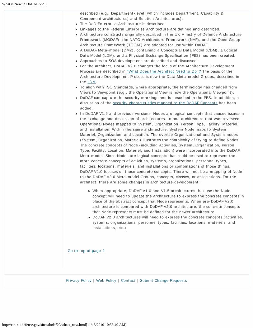
described (e.g., Department-level [which includes Department, Capability &Component architectures] and Solution Architectures).The DoD Enterprise Architecture is described.Linkages to the Federal Enterprise Architecture are defined and described.Architecture constructs originally described in the UK Ministry of Defence ArchitectureFramework (MODAF), the NATO Architecture Framework (NAF), and the Open GroupArchitecture Framework (TOGAF) are adopted for use within DoDAF.A DoDAF Meta-model (DM2), containing a Conceptual Data Model (CDM), a LogicalData Model (LDM), and a Physical Exchange Specification (PES) has been created.Approaches to SOA development are described and discussed.For the architect, DoDAF V2.0 changes the focus of the Architecture DevelopmentProcess are described in “What Does the Architect Need to Do”? The basis of theArchitecture Development Process is now the Data Meta-model Groups, described inthe LDM.To align with ISO Standards, where appropriate, the terminology has changed fromViews to Viewpoint (e.g., the Operational View is now the Operational Viewpoint).DoDAF can capture the security markings and is described in the PES. In addition, adiscussion of the security characteristics mapped to the DoDAF Concepts has beenadded.In DoDAF V1.5 and previous versions, Nodes are logical concepts that caused issues inthe exchange and discussion of architectures. In one architecture that was reviewed,Operational Nodes mapped to System, Organization, Person Type, Facility, Materiel,and Installation. Within the same architecture, System Node maps to System,Materiel, Organization, and Location. The overlap Organizational and System nodes(System, Organization, Material) illustrates the complexity of trying to define Nodes.The concrete concepts of Node (including Activities, System, Organization, PersonType, Facility, Location, Materiel, and Installation) were incorporated into the DoDAFMeta-model. Since Nodes are logical concepts that could be used to represent themore concrete concepts of activities, systems, organizations, personnel types,facilities, locations, materiels, and installations or combinations of those things,DoDAF V2.0 focuses on those concrete concepts. There will not be a mapping of Nodeto the DoDAF V2.0 Meta-model Groups, concepts, classes, or associations. For thearchitect, there are some changes in architecture development:
When appropriate, DoDAF V1.0 and V1.5 architectures that use the Nodeconcept will need to update the architecture to express the concrete concepts inplace of the abstract concept that Node represents. When pre-DoDAF V2.0architecture is compared with DoDAF V2.0 architecture, the concrete conceptsthat Node represents must be defined for the newer architecture.DoDAF V2.0 architectures will need to express the concrete concepts (activities,systems, organizations, personnel types, facilities, locations, materiels, andinstallations, etc.).
Go to top of page ?
Privacy Policy | Web Policy | Contact | Submit Change Requests

DoDAF 2.0 Vision
http://cio-nii.defense.gov/sites/dodaf20/vision.html[11/18/2010 10:56:59 AM]
Home DoDAF-DM2 WG DoDAF Journal DoD Meta Data Registry IDEAS Links
DoDAF V2.0 VisionProvide an overarching set of architecture concepts, guidance, best practices, and methodsto enable and facilitate architecture development in support of major decision processesacross all major Departmental programs, Military components, and Capability areas:
Be consistent and complementary to Federal Enterprise Architecture Guidance, asprovided by OMB.Support the DoD CIO in defining and institutionalizing the Net-Centric Data Strategy(NCDS) and Net-Centric Services Strategy (NCSS) of the Department, to include thedefinition, description, development, and execution of services and throughintroduction of SOA Development.Focus on architectural data as information required for making critical decisions;rather than emphasizing individual architecture products. Enable architects to providevisualizations of the derived information through combinations of DoDAF-describedModels and Fit-for-Purpose Views commonly used by decision-makers, enablingflexibility to develop those views consistent with the culture and preferences of theorganization.Provide methods and suggest techniques through which information architects andother developers can create architectures responsive to and supporting Departmentalmanagement practices.
Go to top of page ?
Introduction
What is New in DoDAF V2.0
Vision for DoDAF V2.0
Purpose and Scope
What DoD Managers andExecutives Need to KnowAbout DoDAF
Guidelines
Customer Requirements
DM2 Support for Viewpointsand DoD Key Processes
Architecture Resources
DoDAF V1.5 Support
Relationships to otherFrameworks
Background
Architecture Development
Viewpoints
Models
DM2
Manager Role
Architect Role
Developer Role
Site Map
Department of Defense

DoDAF 2.0 Vision
http://cio-nii.defense.gov/sites/dodaf20/vision.html[11/18/2010 10:56:59 AM]
Privacy Policy | Web Policy | Contact | Submit Change Requests
DoDAF V2.0 Vision - Purpose and Scope
http://cio-nii.defense.gov/sites/dodaf20/purpose.html[11/18/2010 10:57:12 AM]
Home DoDAF-DM2 WG DoDAF Journal DoD Meta Data Registry IDEAS Links
Vision for DoDAF V2.0
Purpose and Scope
The DoDAF provides the guidance needed to establish a common vocabulary for architecturedevelopment, for the exchange of architecture information, and for facilitatinginteroperability between Architectural Descriptions.
Architectures are created for a number of reasons. From a compliance perspective, DoDdevelopment of architectures is compelled by law and policy (i.e., Clinger-Cohen Act, Officeof Management and Budget (OMB) Circular A-130). From a practical perspective, themanagement of large organizations employing sophisticated systems, technologies, andservices in pursuit of often complex joint missions demands a structured, repeatable methodfor evaluating investments and investment alternatives, as well as the ability to implementorganizational change effectively, create new systems, deploy new technologies, and offerservices which add value to decisions and management practices.
Guidance provided by DoDAF V2.0 applies to all architectures developed, maintained, andused within DoD. The DoDAF also provides the foundational constructs to support theconcept of architecture federation at each tier - enabling the sharing of all pertinentarchitecture information - and facilitates creation of the federated version of the DoDEnterprise Architecture.
DoDAF V2.0 provides guidance in all areas of the architecture lifecycle, consistent with bothDoD and OMB Guidance (i.e., Development, Maintenance, and Use of Architectures). It is thefoundation for long-term administration and management of architectural data and itsaccompanying models (templates), views, and consolidated viewpoints.
DoDAF V2.0 also supports SOA development. It provides management guidance ondevelopment of architectural views and viewpoints, based on service requirements. Itprovides the technical information needed, data views, and other supporting resources fordevelopment of services-based architectures.
Developing Architectures
Careful scoping and organization by managers of the architecture development effort focuseson areas of change indicated by policy or contract in support of the stated goals andobjectives. A data-centric, rather than product-centric, architecture framework ensuresconcordance across architectural views (i.e., that data in one view is the same in anotherview when talking about the same thing, such as an activity). It enables the federation of allpertinent architecture information, and provides full referential integrity. Logical consistencyof the data thus becomes a critical ‘property’ of architectures of all types.
DoDAF V2.0 describes two major types of architectures that contribute to the DoD EnterpriseArchitecture: the Enterprise-level architecture and the Solution Architecture. Each ofthese architectures serves a specific purpose, as described briefly below:
Enterprise Architectures: A strategic information asset base, which defines themission, the information necessary to perform the mission, the technologiesnecessary to perform the mission, and the transitional processes for implementingnew technologies in response to changing mission needs. EA includes a baselinearchitecture, a target architecture, and a sequencing plan. Instances of EnterpriseArchitectures include Capability, Segment, Mission Thread, and Strategic
Introduction
What is New in DoDAF V2.0
Vision for DoDAF V2.0
Purpose and Scope
What DoD Managers andExecutives Need to KnowAbout DoDAF
Guidelines
Customer Requirements
DM2 Support for Viewpointsand DoD Key Processes
Architecture Resources
DoDAF V1.5 Support
Relationships to otherFrameworks
Background
Architecture Development
Viewpoints
Models
DM2
Manager Role
Architect Role
Developer Role
Site Map
Department of Defense

DoDAF V2.0 Vision - Purpose and Scope
http://cio-nii.defense.gov/sites/dodaf20/purpose.html[11/18/2010 10:57:12 AM]
Architectures.Solution Architectures: A framework or structure that portrays the relationshipsamong all the elements of something that answers a problem. This architecture typeis used to define a particular project to create, update, revise, or delete establishedactivities in the Department. Solution architecture may be developed to update orextend another architecture. A Solution Architecture is the most common type ofarchitecture developed in the Department.
Version 1.0 and 1.5 of the DoDAF used the term ‘product’ or ‘products’ to describevisualizations of architecture data. In DoDAF V2.0, the term ‘DoDAF-described Model’ isgenerally used, unless there is a specific reference to the products of earlier versions. ForDoDAF-described Models that have been populated or created with architectural data, theterm ‘Views’ is used. The term “Fit-for-Purpose Views” is used when DoDAF describedmodels are customized or combined for the decision-maker’s need.
The Models described in DoDAF, including those that are legacy views from previous versionsof the Framework, are provided as pre-defined examples that can be used when developingpresentations of architecture data. DoDAF does not prescribe any particular models, butinstead concentrates on data as the necessary ingredient for architecture development. Keyprocess owners will decide what architectural data is required, generally through DoDAF-described Models or Fit-for-Purpose Views. However, other regulations and instructions fromboth DoD and CJCS have particular presentation view requirements. The architectural datadescribed in DoDAF V2.0 can support many model and view requirements; the regulationsand instructions should be consulted for specific model and view requirements.
Maintaining and Managing Architectures
Embedding architecture development process in routine planning and decision-makinginstitutionalizes the architecture and makes the maintenance of architectural data, views,and viewpoints more automatic. Architectures are maintained and managed within theDepartment through a process of tiered accountability. Tiered accountability is thedistribution of authority and responsibility for development, maintenance, CM, and reportingof architectures, architecture policy, tools, and related architecture artifacts to all fourdistinct tiers within the DoD. DoDAF V2.0 supports four tiers: Department, JCA, Component,and Solution (i.e., program or project-level solutions development). These tiers support thefederated approach for architecture development and maintenance.
Using Architectures
Architectures are used to support major DoD decision-making processes, including JCIDS,DAS, PPBE, SE, and PfM processes. Other major Departmental processes supported arebusiness process reengineering, organizational development, research and development,operations support, and service-oriented solutions. Architectural data and other derivedinformation, based on process-owner or stakeholder input and review, provides decisionmakers with the information necessary to support specific decisions in those processes.
Go to top of page ?
Privacy Policy | Web Policy | Contact | Submit Change Requests

DoDAF V2.0 Vision - What DoD Managers and Executives Need to Know About DoDAF
http://cio-nii.defense.gov/sites/dodaf20/need_to_know.html[11/18/2010 10:57:28 AM]
Home DoDAF-DM2 WG DoDAF Journal DoD Meta Data Registry IDEAS Links
Vision for DoDAF V2.0
What DoD Managers and Executives Need to Know About DoDAF
Architecture development is a management tool that supports the decision-making process.A Process owner (an executive responsible for a specific process or program) has the directresponsibility for ensuring that a particular process or program works efficiently, incompliance with legal and departmental requirements, and serves the purpose for which itwas created. Periodically a review and evaluation of the efficiency of the program or processis required.
Those requirements for review, to include those detailed in legislation such as the Clinger-Cohen Act and OMB Directive A-130, include the need to create or update an informationarchitecture supporting any budget requests for funding of those projects and processes. Amanager or executive may delegate the responsibility for creation of the architecture to anarchitect with the professional qualifications needed, along with an architecture developmentteam. However, that delegation of authority does not alter the continuing responsibility ofthe executive or manager. The decision-maker needs to be actively involved in thearchitecture development process and support Architectural Description development. Activeinvolvement means that the decision-maker:
Identifies the Purpose and Scope for the Architecture. The 6-Step ArchitectureDevelopment Process provides a structure for development of scope and purpose.Transmits to the architect and development team the scope and purpose of thearchitecture effort, along with those goals and objectives that support the need.In conjunction with the architect, identifies the general data categories needed forarchitecture development; assists in data collection and validation.Determines desired views and presentation methods for the completed architecture.Meets frequently with the architect and development team to ensure that thedevelopment effort is on target (i.e., is "Fit-for-Purpose") and provides new direction,as required to ensure that the development effort meets established requirements.
The figure below shows a more detailed view of the 6-Step Architecture Process, anddepicts the sub-steps that the decision-maker needs to perform in coordination with thearchitect within the 6-Step Architecture Development Process. In each step, the 'Meta-model Groups' referred to by the step is that data in the Meta-model Groups in DM2.
The decision-maker generally performs the following functions:
Reviews the Purpose (Step 1 of the DoDAF Methodology) and Scope (Step 2) with theArchitect. In order for the architecture to be "Fit-for-Purpose," the decision-makerneeds to provide the list of the categories of data needed and a description of how thedata will be used to the Architect. The decision-maker, not the Architect, is thesubject matter expert for the problem to be solved, the decision to be made, or theinformation to be captured and analyzed. The architect is the technical expert whotranslates the decision-maker's requirements into a set of data that can be used byengineers and analysts to design possible solutions. Determining the data needed andthe requirements (Step 3.1) to be applied is an important responsibility for thedecision-maker and cannot be delegated to the Architect.
Introduction
What is New in DoDAF V2.0
Vision for DoDAF V2.0
Purpose and Scope
What DoD Managers andExecutives Need to KnowAbout DoDAF
Guidelines
Customer Requirements
DM2 Support for Viewpointsand DoD Key Processes
Architecture Resources
DoDAF V1.5 Support
Relationships to otherFrameworks
Background
Architecture Development
Viewpoints
Models
DM2
Manager Role
Architect Role
Developer Role
Site Map
Department of Defense

DoDAF V2.0 Vision - What DoD Managers and Executives Need to Know About DoDAF
http://cio-nii.defense.gov/sites/dodaf20/need_to_know.html[11/18/2010 10:57:28 AM]
Assists with data collection, or provides the data needed (Step 4.1) using thearchitecture collection method described in the Architect's detailed process (Step 4.3).In that step, the architect determines the appropriate collection methods for the "Fit-for-Purpose" needs. The LDM contains a Method subsection for each of the Meta-model groups, which provides potential collection methods. Step 3 includes thoseactions taken to ensure that data integration occurs across all views created as a partof the architecture development effort.Verifies with the architect that the data collected meets the need (Step 5.1) describedin use-cases to support the analysis that will be performed in Step 5 of the 6-StepArchitecture Development Process. The architect has collected the architectural datathat will meet the decision-maker's purpose ("Fit-for-Purpose") and support thedecision review processes. The LDM contains a Use subsection for each of the Meta-model groups, which provides example uses.Determines the appropriate views for the "Fit-for-Purpose" needs and support todecision deliberations (Step 6.1). The DoDAF described Models describes each of theDoDAF-described Models. This step results in presentation creation in Step 6 of the 6-Step Architecture Development Process.
What the Decision-Maker Needs to Do
Working with the architect and team, the decision-maker has a critical role in ensuring thatthe architecture not only supports the creation of executable requirements that will achievethe desired outcome, but also that senior executives and managers can view the desiredsolution in an understandable and logical manner.
Go to top of page ?
Privacy Policy | Web Policy | Contact | Submit Change Requests

DoDAF V2.0 Vision - Guidelines
http://cio-nii.defense.gov/sites/dodaf20/guidelines.html[11/18/2010 10:58:01 AM]
Home DoDAF-DM2 WG DoDAF Journal DoD Meta Data Registry IDEAS Links
Vision for DoDAF V2.0
Guidelines
DoDAF Development Guidelines
DoDAF V2.0 provides comprehensive and practical guidance for the creation of ArchitecturalDescriptions that provide added value for decision-making at the level of the DoD for whichthey are produced. The framework offers guiding principles in the development ofArchitectural Descriptions that transcend the tier, level, or purpose of the architecturedevelopment, and a logical method for executing the development of ArchitecturalDescriptions for supporting critical decisions within key DoD management and changemanagement processes. It also offers flexibility in approach, toolset utilization, andtechniques (e.g., structured analysis, object-oriented, and service-oriented).
Guiding Principles
Guiding principles are high-level concepts, which provide a general roadmap for success indeveloping Architectural Descriptions under DoDAF V2.0. The principles are:
Focus: Architectural Descriptions should clearly support the stated objectives, i.e., be“Fit-for-Purpose.” While DoDAF V2.0 describes a number of models, diligent scoping ofa project and any guiding regulations, instructions, or standard procedures willdetermine the specific visualization requirements appropriate to a particulararchitectural effort.Efficiency: Architectural Descriptions should be as simple and straightforward aspossible, while still achieving their stated purpose. Architectural descriptions shouldreflect the level of complexity defined by the purpose for their creation. Rigorousscoping of a project will ensure that the resulting architectural data, derivedinformation, and the views created are consistent with their original purpose.Collecting and organizing architectural data for use in decision processes should not be‘over done’, that is the depth and breadth of data collected should be sufficient tocapture the major processes actions, and not be so broad that the original intent ofthe architecture project becomes clouded.Clarity: Architectural Descriptions should facilitate, not impede, communications indecision processes and execution. Creation of Architectural Descriptions is meant tosupport decision processes and facilitate improvement of procedures and technology inthe enterprise. It supports the decision-making process and provides a record toexplain critical choices to technical and non-technical managerial staff.Comparability: Architectural Descriptions should be relatable, comparable, andcapable of facilitating cross-architecture analysis. Most Architectural Descriptions,except perhaps those at the highest levels of DoD or an organization, relate on theirboundaries to other external processes and operations. When several processesand/or operations are evaluated, compared, or cross-referenced, it should be clearhow, where, and why data passes among them in similar form.Integration of data: Architectural Descriptions should articulate how datainteroperability is achieved among federated Architectural Descriptions. To enablefederation, the framework will provide structures to ensure that horizontal touch-points can be compared for consistency across Architectural Description boundaries.Other mechanisms will ensure that higher tiers have access to data from lower tiers ina form that supports their decision needs. DoDAF utilizes the DM2, and particularly the
Introduction
What is New in DoDAF V2.0
Vision for DoDAF V2.0
Purpose and Scope
What DoD Managers andExecutives Need to KnowAbout DoDAF
Guidelines
Customer Requirements
DM2 Support for Viewpointsand DoD Key Processes
Architecture Resources
DoDAF V1.5 Support
Relationships to otherFrameworks
Background
Architecture Development
Viewpoints
Models
DM2
Manager Role
Architect Role
Developer Role
Site Map
Department of Defense

DoDAF V2.0 Vision - Guidelines
http://cio-nii.defense.gov/sites/dodaf20/guidelines.html[11/18/2010 10:58:01 AM]
Physical Exchange Specification, as a resource to achieve interoperability. A keyelement in ensuring interoperability is the effort taken to plan for integration of dataacross views, Architectural Description boundaries, and is consistent between tiers.Data-Centricity: Architectural Descriptions should be data centric. The frameworkassists in the design of structures that meet specific needs depending on the prioritiesof individual organizations. In particular, the framework calls for the development ofintegrated, searchable, structured architectural data sets that support analysistargeted to critical decisions.Tool-Agnostic: Multiple toolsets, with varying internal rules, techniques, notations,and methods may be used, consistent with the PES. The framework allows architectsto select techniques and toolsets to meet specific needs. While the frameworkprovides examples of the application of both Structured Analysis and Design (SADT)and Object-Oriented Analysis & Design (OOAD) techniques, it mandates neither. Theframework explicitly permits any technique that meets the needs of the organization,provides the appropriate architectural data, adheres to the architectural datarequirements of parent tiers, and is capable of producing data that can be shared in afederated environment. There are some basic attributes of a toolset needed to ensurethat Architectural Descriptions, once registered, are discoverable, sharable, and theirdata useful to others with similar or derived needs in their own ArchitecturalDescription development. These attributes are:
Capable of utilizing the Physical Exchange Specification to collect, organize, andshare architectural data.Capable of eXtensible Markup Language (XML) data transfer to/fromarchitectural tools and other resources, such as the DoD Architecture RegistrySystem (DARS) for registering architectural data.
Reusability: Architectural data should be organized, reusable, and decomposedsufficiently for use by architectural development teams and decision support analysisteams. Whenever possible, data common to other Architectural Descriptions should beused. New data should be created so that it becomes discoverable to others withsimilar requirements.Net-Centricity: Development of Architectural Descriptions should be guided by theprinciples and practices of net-centricity to facilitate and support the Net-CentricStrategy of the Department. Development of Architectural Descriptions should ensurethat they adhere to net-centric principles, as outlined in the Net-Centric Strategy, andclearly delineate data that must be shared across and between systems or servicesdescribed in the Architectural Description.Multiple Techniques and Toolsets, Including Structured and Object OrientedAnalysis: The framework allows architects to select techniques and toolsets to meetspecific needs. While the framework provides examples of the application of bothStructured Analysis and Design (SADT) and Object-Oriented Analysis & Design(OOAD) techniques, it mandates neither. The framework explicitly permits anytechnique that meets the needs of the organization, provides the appropriatearchitectural data, adheres to the architectural data requirements of parent tiers andis capable of producing data that can be shared in a federated environment. Eessentialtoolset attributes desirable for creation of Architectural Descriptions utilizing DoDAFare listed below.Essential Toolset Attributes: While DoDAF is toolset agnostic, allowing architects,and Architectural Description development teams to utilize any toolset they desire tocreate Architectural Descriptions, there are some basic attributes of a toolset neededto ensure that Architectural Descriptions, once registered, are discoverable, sharable,and their data useful to others with similar or derived needs in their own ArchitecturalDescription development. These attributes are:
Capable of utilizing the PES to collect, organize, and share architectural data.Capable of eXtensible Markup Language (XML) data transfer to/from the DMR,and other resources for registering architectural data.

DoDAF V2.0 Vision - Guidelines
http://cio-nii.defense.gov/sites/dodaf20/guidelines.html[11/18/2010 10:58:01 AM]
Tailoring Architecture to Customers’ Needs
Detail on specific implementations of the basic processes, including explicitidentification of critical decisions mandated or implied.Identification of performance measures that can be used to judge the effectiveness ofeach process (including any mandated by the authoritative documents), taking specialnote of those that sample the effectiveness of Architectural Description support (theDoDAF Journal includes a tutorial on a relatively painless method for performanceengineering).For each critical decision, identification of at least one method (and optionally severalalternatives) for making that decision, identifying analyses to perform and questionsto answer.For each analysis or question, identification of needed information.Creation of additional business objects/elements and attributes as needed to captureinformation in the architecture repository.Process and information definitions for utilization in Architectural Descriptiondevelopment.The architect simplifies the architectural design by eliminating unneeded objects andattributes through a ‘best sense of opportunity’ approach, whereby interaction withthe customer provides normal and expected needs that generally satisfies themajority of information needs for Architectural Description development. Architecturalviews should be created to reflect, as closely as possible, the normal ‘culture’, andpreferred presentation design of the agency.
Go to top of page ?
Privacy Policy | Web Policy | Contact | Submit Change Requests

DoDAF V2.0 Vision - Customer Requirements
http://cio-nii.defense.gov/sites/dodaf20/customer.html[11/18/2010 10:58:23 AM]
Home DoDAF-DM2 WG DoDAF Journal DoD Meta Data Registry IDEAS Links
Vision for DoDAF V2.0
Customer Requirements
In a large organization such as DoD, there are myriad decisions made each day. Thesedecisions require facts (i.e., valid information) for successful execution. Two things affect theability to make decisions. First, information must be available; second, a decision supportprocess must exist to frame how the decision, once made, can be executed. Decision supportcan be as simple as an established procedure or rule for execution, or a more complex,integrated set of actions to ensure that a decision is executed properly.
Within DoD are a number of very complex, overarching, decision support services thatprovide a framework for execution on DoD’s most critical program activities. These key DoDchange management decision support processes include JCIDS, DAS, SE, PPBE, and PfM. Thefollowing paragraphs discuss how these key decision support processes use architectural datato influence management decision making.
Tailoring Architecture to Customers’ Needs
Architectural Descriptions are collections of information about an organization that is relevantto a requirement. This information frequently includes processes, supporting systems,needed or desired services, interfaces, business rules, and other details that can beorganized to facilitate a decision. From this perspective, Architecture applies a method fortailoring information collection to a specific local need with a clear understanding of thedecisions the Architectural Description needs to support, how those decisions should bemade, and what information they require. Responding to the organization’s requirementsgenerally requires the following information to apply the methodology or another selected bythe architect:
Detail on specific implementations of the basic processes, including explicitidentification of critical decisions mandated or implied.Identification of performance measures that can be used to judge the effectiveness ofeach process (including any mandated by the authoritative documents), taking specialnote of those that sample the effectiveness of Architectural Description support (theDoDAF Journal includes a tutorial on a relatively painless method for performanceengineering).For each critical decision, identification of at least one method (and optionally severalalternatives) for making that decision, identifying analyses to perform and questionsto answer.For each analysis or question, identification of needed information.Creation of additional business objects/elements and attributes as needed to captureinformation in the architecture repository.Process and information definitions for utilization in Architectural Descriptiondevelopment.
The architect simplifies the architectural design by eliminating unneeded objects andattributes through a ‘best sense of opportunity’ approach, whereby interaction with thecustomer provides normal and expected needs that generally satisfies the majority ofinformation needs for Architectural Description development. Architectural views should becreated to reflect, as closely as possible, the normal ‘culture’, and preferred presentationdesign of the agency.
Introduction
What is New in DoDAF V2.0
Vision for DoDAF V2.0
Purpose and Scope
What DoD Managers andExecutives Need to KnowAbout DoDAF
Guidelines
Customer Requirements
DM2 Support for Viewpointsand DoD Key Processes
Architecture Resources
DoDAF V1.5 Support
Relationships to otherFrameworks
Background
Architecture Development
Viewpoints
Models
DM2
Manager Role
Architect Role
Developer Role
Site Map
Department of Defense

DoDAF V2.0 Vision - Customer Requirements
http://cio-nii.defense.gov/sites/dodaf20/customer.html[11/18/2010 10:58:23 AM]
Key Decision Support Processes
Organizations within the DoD may define local change management processes, supportableby Architectural Descriptions, while adhering to defined decision support processes mandatedby the Department, including JCIDS, the DAS, SE, PPBE, Net-centric Integration, and PfM.These key support processes are designed to provide uniform, mandated, processes incritical decision-making areas, supplemented by individual agency operations, defined byArchitectural Descriptions tailored to support those decisions-making requirements.
Joint Capability Integration and Development System
The primary objective of the JCIDS process is to ensure warfighters receive the capabilitiesrequired to execute their assigned missions successfully. JCIDS defines a collaborativeprocess that utilizes joint concepts and integrated Architectural Descriptions to identifyprioritized capability gaps and integrated joint Doctrine, Organization, Training, Materiel,Leadership and Education, Personnel, and Facilities (DOTMLPF) and policy approaches(materiel and non-materiel) to resolve those gaps. JCIDS implements an integrated,collaborative process to guide development of new capabilities through changes in jointDOTMLPF and policy.
JCIDS process owners have written policy to support architecture requirements (i.e., specificproduct sets required in specific documents, such as the Information Support Plan, CapabilityDevelopment Document, and Capability Production Document) that permits components andlower echelon commands to invoke the JCIDS process for requirements at all levels.
Defense Acquisition System
The DAS exists to manage the nation’s investments in technologies, programs, and productsupport necessary to achieve the National Security Strategy and support employment andmaintenance of the United States Armed Forces. The DAS uses Joint Concepts, integratedarchitectures, and DOTMLPF analysis in an integrated, collaborative process to ensure thatdesired capabilities are supported by affordable systems and other resources.
DoD Directive 5000.1 provides the policies and principles that govern the DAS. In turn, DoDInstruction 5000.2, Operation of the DAS establishes the management framework fortranslating mission needs and technology opportunities, based on approved mission needsand requirements, into stable, affordable, and well-managed acquisition programs thatinclude weapon systems and automated information systems (AISs). The Defense AcquisitionManagement Framework provides an event-based process where acquisition programsadvance through a series of milestones associated with significant program phases.
The USD (AT&L) leads the development of integrated plans or roadmaps using integratedarchitectures as its base. DoD organizations use these roadmaps to conduct capabilityassessments, guide systems development, and define the associated investment plans as thebasis for aligning resources and as an input to the Defense Planning Guidance (DPG),Program Objective Memorandum (POM) development, and Program and Budget Reviews.
Systems Engineering
DoD Acquisition policy directs all programs responding to a capabilities or requirementsdocument, regardless of acquisition category, to apply a robust SE approach that balancestotal system performance and total cost with the family-of-systems, and system-of-systemscontext. Programs develop a Systems Engineering Plan (SEP) for Milestone DecisionAuthority (MDA) that describes the program’s overall technical approach, including activities,resources, measures (metrics), and applicable performance incentives.
SE processes are applied to allow an orderly progression from one level of development tothe next detailed level using controlled baselines. These processes are used for the system,subsystems, and system components as well as for the supporting or enabling systems usedfor the production, operation, training, support, and disposal of that system. Execution oftechnical management processes and activities, such as trade studies or risk managementactivities may point to specific requirements, interfaces, or design solutions as non-optimaland suggest change to increase system-wide performance, achieve cost savings, or meet

DoDAF V2.0 Vision - Customer Requirements
http://cio-nii.defense.gov/sites/dodaf20/customer.html[11/18/2010 10:58:23 AM]
scheduling deadlines.
Architecture supports SE by providing a structured approach to document design anddevelopment decisions based on established requirements.
Planning, Programming, Budgeting, and Execution
The PPBE process allocates resources within the DoD and establishes a framework andprocess for decision-making on future programs. PPBE is a systematic process that guidesDoD’s strategy development, identification of needs for military capabilities, programplanning, resource estimation, and allocation, acquisition, and other decision processes.JCIDS is a key supporting process for PPBE, providing prioritization and affordability advice.
DoDAF V2.0 supports the PPBE process by identifying the touch points between architectureand the PPBE process, identifying the data to be captured within an ArchitecturalDescription, facilitating informed decision-making, and identifying ways of presenting data tovarious stakeholders/roles in the PPBE decision process.
Portfolio Management
DoD policy requires that IT investments be managed as portfolios to ensure IT investmentssupport the Department’s vision, mission, and goals; ensure efficient and effective deliveryof capabilities to the Warfighter; and maximize return on investment within the enterprise.Each portfolio may be managed using the architectural plans, risk management techniques,capability goals and objectives, and performance measures. Capability architecting is doneprimarily to support the definition of capability requirements. PfM uses the ArchitecturalDescription to analyze decisions on fielding or analysis of a needed capability.
Architectural support to PfM tends to focus on the investment decision itself (although notexclusively), and assists in justifying investments, evaluating the risk, and providing acapability gap analysis.
Operations
In most cases, an enterprise will capture its routine or repeatable business and missionoperations as architectural content. However, when the basic structure of an activity is verystable and the activity repeated often, such as military operations planning or projectdefinition and management, the enterprise may choose to include that structure as part ofthe Architectural Description itself. In this case, the architecture repository may be enhancedto include templates, checklists, and other artifacts commonly used to support the activity.
The JCIDS, PPBE, and DAS processes establish a knowledge-based approach, which requiresprogram managers to attain the right knowledge at critical junctures to make informedprogram decisions throughout the acquisition process. The DoD IT PfM process continues toevolve that approach with emphasis on individual systems and/or services designed toimprove overall mission capability. Consistent with OMB Capital Planning and InvestmentControl (CPIC) guidance, the DoD uses four continuous integrated activities to manage itsportfolios – analysis, selection, control, and evaluation. The overall process is iterative, withresults being fed back into the system to guide future decisions.
Net-centric Integration
Net-centric Integration and interoperability requirements, to include supporting architecturalviews, are required by CJCSI 6212.01E . DoDAF V2.0 provides views that supportinteroperability requirements, both in DoDAF-described Models (including those fromprevious versions of DoDAF), and new viewpoints. The DM2 provides data support tointeroperability requirements and facilitates creation of user-defined views that meetspecific, “Fit-for-Purpose” requirements.
Information Sharing
Information sharing across the Department has existed for many years in various forms. Thesharing of information took on new urgency following the events of September 2001,especially in the area of terrorist-related information. Since that time, new Federal legislationand presidential orders require that agencies develop a common framework for the sharing

DoDAF V2.0 Vision - Customer Requirements
http://cio-nii.defense.gov/sites/dodaf20/customer.html[11/18/2010 10:58:23 AM]
of information, and define common standards for how information is acquired, accessed,shared, and used within a newly created Information Sharing Environment (ISE). Whileinitial efforts relate to terrorism-related data, the standards being set could apply, in thefuture, more broadly across the Department.
Importantly, an Information Sharing Environment Enterprise Architecture Framework (ISE-EAF) is under development, which will provide guidance for information collection anddissemination within the Information Sharing Environment (ISE). This Framework isconsistent with the DoDAF, and is essential data structures will be mappable to the DM2.When published, that ISE document should be used in coordination with DoDAF to ensurethat these specific types of data meet established Federal standards.
Go to top of page ?
Privacy Policy | Web Policy | Contact | Submit Change Requests

DoDAF V2.0 Vision - DM2 Support for Viewpoints and DoD Key Processes
http://cio-nii.defense.gov/sites/dodaf20/DM2_support.html[11/18/2010 10:58:45 AM]
Home DoDAF-DM2 WG DoDAF Journal DoD Meta Data Registry IDEAS Links
Vision for DoDAF V2.0
DM2 Support for Viewpoints and DoD Key Processes
The DoDAF V2.0 Meta-model Groups support the viewpoints and DoD Key Processes ofJCIDS, DAS, PPBE, System Engineering, Operations, and Portfolio Management (IT andCapability). The table below indicates a non-inclusive mapping of DoDAF Meta-model Groupsto the DoDAF Viewpoints and DoD Key Processes. The support for the Key Processes is forthe information requirements that were presented at the workshops for the key processesand, as such, do not reflect all of the information requirements that a key process couldneed.
DoDAF Meta-model Groups Mapping to Viewpoints and DoD Key Processes
MetamodelData Groups
View Points DoD Key Processes
AV, CV, DIV,OV,PV,StdV,SvcV, SV
JCIDS, DAS, PPBE, SystemEngineering, Operations,Portfolio Management (IT
and Capability)
Performer CV, OV, PV,StdV, SvcV, SV J, D, P, S, O, C
Activity OV J, O, C
Resource Flow AV, CV, DIV,OV,PV,StdV J, S, O
Data and Information AV, DIV J, D, P, S, O, C
Capability CV, PV, SV, SvcV J, D, P, S, O, C
Services CV, StdV, SV P, S, C
Project AV, CV, PV, SvcV, SV D, P, S, C
Training/Skill/Education OV, SV, SvcV, StdV J, S, O
Goals CV, PV J, D, P, O, C
Rules OV, StdV, SvcV, SV J, D, S, O
Measures SvcV, SV J, D, S, O, C
Location SvcV, SV P, S, O
Go to top of page ?
Introduction
What is New in DoDAF V2.0
Vision for DoDAF V2.0
Purpose and Scope
What DoD Managers andExecutives Need to KnowAbout DoDAF
Guidelines
Customer Requirements
DM2 Support for Viewpointsand DoD Key Processes
Architecture Resources
DoDAF V1.5 Support
Relationships to otherFrameworks
Background
Architecture Development
Viewpoints
Models
DM2
Manager Role
Architect Role
Developer Role
Site Map
Department of Defense

DoDAF V2.0 Vision - DM2 Support for Viewpoints and DoD Key Processes
http://cio-nii.defense.gov/sites/dodaf20/DM2_support.html[11/18/2010 10:58:45 AM]
Privacy Policy | Web Policy | Contact | Submit Change Requests

DoDAF Architecture Resources
http://cio-nii.defense.gov/sites/dodaf20/arch_resource.html#top[11/18/2010 10:59:10 AM]
Home DoDAF-DM2 WG DoDAF Journal DoD Meta Data Registry IDEAS Links
Architectural Resources
A number of architecture resources exist which serve as sources for guidelines that shouldbe consulted while building architectural views. Some of these architecture resources arebriefly listed below, with their architectural uses, and their URLs. Additional information iscontained in the individual URLs. Some architecture resources require Secret InternetProtocol Router Network (SIPRNET) access.
Architecture Resources
Resource Description Architecture Use URL
Departmentof DefenseInformationEnterpriseArchitecture(DoD IEA)
Defines the keyprinciples, rules,constraints andbest practices towhich applicableDoD programs,regardless ofComponent orportfolio, mustadhere in order toenable agile,collaborative net-centric operations.
The DoD IEA providesthe guidelines and rulesthat the architect mustkeep in mind in thearchitecturedevelopment effort.
http://cio-nii.defense.gov/sites/diea/index.html
DoDArchitectureRegistrySystem(DARS)
DARS is the DoDregistry ofsegment andsolutionarchitecturescomprising thefederated DoDenterprisearchitecture.
To discoverarchitectures that exist,or may be indevelopment.Depending on thepurpose and scope, anarchitect may searchand discoverArchitectures thatoverlap the scope andpurpose of thearchitecture effort. Toregister metadataabout architecturesthat are beingdeveloped, or currentlyexist.
https://dars1.army.mil
DoDInformationTechnologyPortfolioRepository(DITPR)
The officialunclassified DoDdata source forFederalInformationSecurityManagement Act
The Systems metadatafrom the Architecturecan be used topopulate DITPR withnew or updatedinformation. DITPR canalso populate the
https://www.dadms.navy.mil/
Introduction
What is New in DoDAF V2.0
Vision for DoDAF V2.0
Architecture Resources
DoDAF V1.5 Support
Relationships to otherFrameworks
Background
Architecture Development
Viewpoints
Models
DM2
Manager Role
Architect Role
Developer Role
Site Map
Department of Defense

DoDAF Architecture Resources
http://cio-nii.defense.gov/sites/dodaf20/arch_resource.html#top[11/18/2010 10:59:10 AM]
(FISMA), E-Authentication,PortfolioManagement,Privacy ImpactAssessments, theinventory ofMC/ME/MSsystems, and theregistry forsystems underDoDI 5000.2.
architecture’s Systemsmetadata, particularlyon systems thatinterface with systemsdescribed in thearchitecture, but arenot part of the scope ofthe architecture.
DoDInformationTechnologyStandardsandProfileRegistry(DISR)
Online repositoryfor a minimal setof primarilycommercial ITstandards.
The DISR can be usedto populate theStandards models(StdV-1 and StdV-2) ofthe Architecture.Conversely, theStandards Models canidentify additional ornew standards thatneed to be added toDISR.
https://disronline.disa.mil
Joint C4IProgramAssessmentTool (JCPAT)
Formally assesssystems andcapabilitiesdocuments (InitialCapabilitiesDocument,CapabilityDevelopmentDocument, andCapabilityProductionDocument) forJoint Staffinteroperabilityrequirementscertification and isthe ITS/NSSLifecycleRepository andthe archives.
The ICD, CDD, andCPD containarchitectureinformation. As thearchitecturedevelopmentprogresses, thecollected architectureinformation can beextracted and reportedin the ICD, CDD, andthe CPD. In addition,the architectureinformation can bewithin with theEnhanced-InformationSupport Plan (E-ISP)tool, a part of theJCPAT toolset.
http://jcpat.ncr.disa.smil.mil/JECOweb.nsf(SIPRNet)
JointCommonSystemFunction List(JCSFL)
A common lexiconofsystems/servicefunctionalitysupporting jointcapability. TheJCSFL is providedfor mappingfunctions tosupportedactivities and thesystems orservices that host
Use the taxonomy toalign or extend systemfunctions within thearchitecture beingdeveloped
https://us.army.mil/suite/page/419489

DoDAF Architecture Resources
http://cio-nii.defense.gov/sites/dodaf20/arch_resource.html#top[11/18/2010 10:59:10 AM]
them. Chairmanof the Joint Chiefsof StaffInstruction(CJCSI) 6212.01Eprescribes theJCSFL for use indeveloping acommonvocabulary forarchitecturedevelopment.
KnowledgeManagement/DecisionSupport(KM/DS)
The KM/DS toolwill be used byDoD componentsto submitdocuments andcomments for O-6and flag reviews,search forhistoricalinformation, andtrack the status ofdocuments.
Supporting the JCIDSapproval process, thedocuments that arenecessary for MilestoneDecisions havearchitectureinformation. As thearchitecturedevelopmentprogresses, thecollected architectureinformation can beextracted and reportedin the requireddocuments.
https://jrockmds1.js.smil.mil/guestjrcz/gbase.guesthom(SIPRNet)
MetadataRegistry
The DoD MetadataRegistry andClearinghouseprovides softwaredevelopers accessto datatechnologies tosupport DoDmissionapplications.Through theMetadata RegistryandClearinghouse,softwaredevelopers canaccess registeredXML data andmetadatacomponents,databasesegments, andreference datatables and relatedmetadatainformation
The Resource Flowsand Physical Schemasfrom the Architecturecan be used topopulate the MetadataRegistry.
http://metadata.dod.mil
NavalArchitectureElements
A standard termsof reference forthe Navy and
The use of the criticaltaxonomies is a step toensuring integration of
https://stalwart.spawar .navy.mil/naerg/
DoDAF Architecture Resources
http://cio-nii.defense.gov/sites/dodaf20/arch_resource.html#top[11/18/2010 10:59:10 AM]
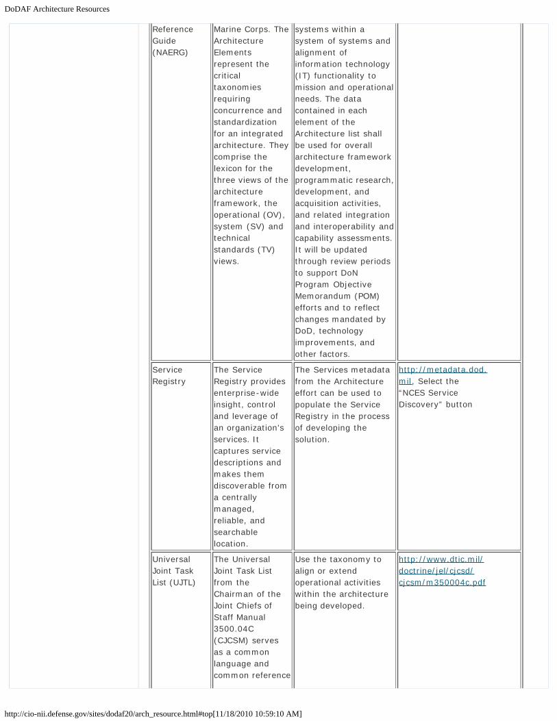
ReferenceGuide(NAERG)
Marine Corps. TheArchitectureElementsrepresent thecriticaltaxonomiesrequiringconcurrence andstandardizationfor an integratedarchitecture. Theycomprise thelexicon for thethree views of thearchitectureframework, theoperational (OV),system (SV) andtechnicalstandards (TV)views.
systems within asystem of systems andalignment ofinformation technology(IT) functionality tomission and operationalneeds. The datacontained in eachelement of theArchitecture list shallbe used for overallarchitecture frameworkdevelopment,programmatic research,development, andacquisition activities,and related integrationand interoperability andcapability assessments.It will be updatedthrough review periodsto support DoNProgram ObjectiveMemorandum (POM)efforts and to reflectchanges mandated byDoD, technologyimprovements, andother factors.
ServiceRegistry
The ServiceRegistry providesenterprise-wideinsight, controland leverage ofan organization'sservices. Itcaptures servicedescriptions andmakes themdiscoverable froma centrallymanaged,reliable, andsearchablelocation.
The Services metadatafrom the Architectureeffort can be used topopulate the ServiceRegistry in the processof developing thesolution.
http://metadata.dod.mil, Select the“NCES ServiceDiscovery” button
UniversalJoint TaskList (UJTL)
The UniversalJoint Task Listfrom theChairman of theJoint Chiefs ofStaff Manual3500.04C(CJCSM) servesas a commonlanguage andcommon reference
Use the taxonomy toalign or extendoperational activitieswithin the architecturebeing developed.
http://www.dtic.mil/doctrine/jel/cjcsd/cjcsm/m350004c.pdf

DoDAF Architecture Resources
http://cio-nii.defense.gov/sites/dodaf20/arch_resource.html#top[11/18/2010 10:59:10 AM]
system for jointforcecommanders,combat supportagencies,operationalplanners, combatdevelopers, andtrainers tocommunicatemissionrequirements. It isthe basiclanguage fordevelopment of ajoint missionessential task list(JMETL) or agencymission essentialtask list (AMETL)that identifiesrequiredcapabilities formission success.
Go to top of page ?
Privacy Policy | Web Policy | Contact | Submit Change Requests

DoDAF V1.5 Support
http://cio-nii.defense.gov/sites/dodaf20/V15support.html[11/18/2010 10:59:32 AM]
Home DoDAF-DM2 WG DoDAF Journal DoD Meta Data Registry IDEAS Links
DoDAF V1.5 SupportThe architectures for DoDAF V1.0 and DoDAF V1.5 may continue to be used. Whenappropriate (usually indicated by policy or by the decision-maker), DoDAF V1.0 and V1.5architectures will need to update their architecture. When pre-DoDAF V2.0 architecture iscompared with DoDAF V2.0 architecture, concept differences (such as Node) must be definedor explained for the newer architecture.
In regard to DoDAF V1.5 products, they have been transformed into parts of the DoDAF V2.0models. In most cases, the DoDAF V2.0 Meta-model supports the DoDAF V1.5 data concepts,with one notable exception: Node. Node is a complex, logical concept that is representedwith more concrete concepts. The table below indicates the mapping of DoDAF V1.5 productsto DoDAF V2.0 models.
Mapping of DoDAF V1.5 Products to DoDAF V2.0 Models
Introduction
What is New in DoDAF V2.0
Vision for DoDAF V2.0
Architecture Resources
DoDAF V1.5 Support
Relationships to otherFrameworks
Background
Architecture Development
Viewpoints
Models
DM2
Manager Role
Architect Role
Developer Role
Site Map
Department of Defense

DoDAF V1.5 Support
http://cio-nii.defense.gov/sites/dodaf20/V15support.html[11/18/2010 10:59:32 AM]
Go to top of page ?
Privacy Policy | Web Policy | Contact | Submit Change Requests

Relationships to other Frameworks
http://cio-nii.defense.gov/sites/dodaf20/relationships.html[11/18/2010 10:59:55 AM]
Home DoDAF-DM2 WG DoDAF Journal DoD Meta Data Registry IDEAS Links
Relationships to Other Architecture Frameworks/ReferenceDocumentsThe DoDAF approach to alignment is to incorporate relevant concepts into DoDAF from otherframeworks and reference documents and understand, integrate and describe thedifferences.
Frameworks
Frameworks are documents that describe useful methods, practices, and procedures fordeveloping Architectural Descriptions. Frameworks can be prescriptive (e.g., their use isrequired) or descriptive (i.e., their use is recommended). DoDAF has both prescriptive anddescriptive elements that organizations within the Department require its use in developingArchitectural Descriptions that respond to their mandates.
Federal Enterprise Architecture Program
The FEA promotes shared development for common Federal processes, interoperability, andsharing of information among the Agencies of the Federal Government and otherGovernmental entities through the use of a set of reference models and practices that applyto all Federal agencies in the Executive branch. The FEA Practice Guidance uses a segmentarchitecture approach that allows critical parts of the overall Federal Enterprise, calledarchitectural segments, to be developed individually, while integrating these segments intothe larger Enterprise Architecture. The DoDAF leverages the FEA construct and coreprinciples to provide the Department with the enterprise management information it needsto achieve its strategic transformation goals, while ensuring that upward reporting andreview can be accomplished against the FEA.
The Zachman Framework
The Zachman Framework provides a formal and highly structured way of defining anenterprise. It is based on a two-dimensional classification model, displayed as a matrix,which utilizes six basic communication interrogatives (What, How, Where, Who, When, andWhy) and intersecting six distinct model types which relate to stakeholder groups(Strategists, Executive Leaders, Architects, Engineers, Technicians, and Workers) to give aholistic view of the enterprise. Decomposition of the matrix allows for several diagrams ofthe same data sets to be developed for the same architecture, where each diagram showsan increasing level of detail. DoDAF V2.0 supports the needs of various stakeholders’perspective by supporting various levels of abstraction and granularity.
The Open Group Architecture Framework
The Open Group Architecture Framework (TOGAF) is a comprehensive architectureframework and methodology, which enables practitioners to design, evaluate, and build anappropriate architecture for the organization. The TOGAF Architecture Development Method(ADM) supports the TOGAF architecture development approach for architectures that meetbusiness needs. TOGAF’s ADM prescribes methodology, not products, or modeling notation,and should be used with other architecture frameworks as appropriate. TOGAF evolved fromthe DoD Technical Architecture Framework for Information Management (TAFIM). DoDAFV2.0 and TOGAF both provide a practical, design agnostic method for creating enterprisearchitectures. The DoDAF V2.0 “Fit-for-Purpose” approach for developing views,presentations, or generated reports are based on TOGAF’s business, data, application, andtechnology views.
The Ministry of Defence Architecture Framework
Introduction
What is New in DoDAF V2.0
Vision for DoDAF V2.0
Architecture Resources
DoDAF V1.5 Support
Relationships to otherFrameworks
Background
Architecture Development
Viewpoints
Models
DM2
Manager Role
Architect Role
Developer Role
Site Map
Department of Defense
Relationships to other Frameworks
http://cio-nii.defense.gov/sites/dodaf20/relationships.html[11/18/2010 10:59:55 AM]
Ministry of Defence Architecture Framework (MODAF) is based on the DoDAF V1.0 baseline,which it represents through the MODAF Meta Model (M3). MODAF retains compatibility withUnited States modeling initiatives, but is specifically designed to support architecturemodeling for the UK Ministry of Defense (MOD) business. MODAF uses aspects of the existingDoDAF with additional viewpoints (acquisition, capability) that are required to support MODprocesses, procedures, and organizational structures. The additional viewpoints provide arigorous method for understanding, analyzing, and specifying capabilities, systems, Systemof Systems (SoS), business processes, and organizational structures. DoDAF V2.0incorporates the data elements from MODAF required to support an acquisition and capabilityviews in DoDAF V2.0.
NATO Architecture Framework
The NAF provides the rules, guidance, and product descriptions for developing, presenting,and communicating architectures across NATO and other national boundaries. Earlierversions of NAF were tightly coupled to the DoDAF. NAF’s new features include a Capability,Service-oriented, and Program view. DoDAF V2.0 has adopted the capability and programviews described in NAF as defined by NAF.
Reference Architectures
The Architectures described below have a particular impact on the development ofArchitectural Descriptions in the Department:
DoD Information Enterprise Architecture
The DoD Information Enterprise Architecture (IEA) provides a common foundation to supportaccelerated DoD transformation to net-centric operations and establishes priorities toaddress critical barriers to its realization. The DoD IEA comprises the information,information resources, assets, and processes required to achieve an information advantageand share information across the Department, and with other mission partners.
DoD Business Enterprise Architecture
The DoD Business Enterprise Architecture (BEA) Architectural Description provides acomprehensive description of the major business areas of the Department, and serves thedeparture point for integrating DoD business services across the Departmental programs andthe JCAs.
DoD Global Information Grid Enterprise Architecture
The GIG facilitates mission accomplishment by providing tactical services from the edge insupport of the warfighter. The GIG Architectural Description maps operational outcomes incritical strategic and tactical areas to the DoD JCAs. Currently, the GIG contains anOperational Reference Model which provides a functional decomposition of activitiesassociated with the five key areas defined as GIG 2.0 attributes.
Go to top of page ?
Privacy Policy | Web Policy | Contact | Submit Change Requests

DoDAF Background
http://cio-nii.defense.gov/sites/dodaf20/background.html[11/18/2010 11:00:21 AM]
Home DoDAF-DM2 WG DoDAF Journal DoD Meta Data Registry IDEAS Links
DoDAF BackgroundAuthority: Law, Policy, and Historic Perspective
Federal law and policies have expressed the need for architectures in support of businessdecisions.
Federal Law and Policy
Policy/Guidance Description
Clinger-Cohen Act of1996
Recognizes the need for Federal Agencies to improve the waythey select and manage IT resources and states, “informationtechnology architecture, with respect to an executive agency,means an integrated framework for evolving or maintaining ITand acquiring new IT to achieve the agency’s strategic goals andinformation resources management goals.” Chief InformationOfficers are assigned the responsibility for “developing,maintaining, and facilitating the implementation of a sound andintegrated IT architecture for the executive agency”.
E-Government Act of2002
Calls for the development of Enterprise Architecture to aid inenhancing the management and promotion of electronicgovernment services and processes.
Office of Managementand Budget Circular A-130
“Establishes policy for the management of Federal informationresources” and calls for the use of Enterprise Architectures tosupport capital planning and investment control processes.Includes implementation principles and guidelines for creatingand maintaining Enterprise Architectures.
OMB Federal EnterpriseArchitecture ReferenceModels (FEA RM)
Facilitates cross-agency analysis and the identification ofduplicative investments, gaps, and opportunities for collaborationwithin and across Federal Agencies. Alignment with the referencemodels ensures that important elements of the FEA aredescribed in a common and consistent way. The DoD EnterpriseArchitecture Reference Models are aligned with the FEA RM.
OMB EnterpriseArchitecture AssessmentFramework (EAAF)
Serves as the basis for enterprise architecture maturityassessments. Compliance with the EAAF ensures that enterprisearchitectures are advanced and appropriately developed toimprove the performance of information resource managementand IT investment decision making.
General AccountingOffice EnterpriseArchitecture ManagementMaturity Framework(EAMMF)
“Outlines the steps toward achieving a stable and mature processfor managing the development, maintenance, andimplementation of enterprise architecture.” Using the EAMMFallows managers to determine what steps are needed forimproving architecture management.
Historical Evolution of DoDAF
Introduction
What is New in DoDAF V2.0
Vision for DoDAF V2.0
Architecture Resources
DoDAF V1.5 Support
Relationships to otherFrameworks
Background
Architecture Development
Viewpoints
Models
DM2
Manager Role
Architect Role
Developer Role
Site Map
Department of Defense

DoDAF Background
http://cio-nii.defense.gov/sites/dodaf20/background.html[11/18/2010 11:00:21 AM]
Historical Evolution of DoDAF The Command, Control, Communications, Computers, andIntelligence, Surveillance, and Reconnaissance Architecture Framework (C4ISR AF) v1.0,dated 7 June 1996, was created in response to the passage of the Clinger-Cohen Act. Itreplaced the Technical Architecture for Information Management (TAFIM). Version 2.0 of theC4ISR Framework was published on 18 December 1997.
The DoDAF V1.0, dated 30 August 2003 restructured the C4ISR Framework V2.0 andbroadened the applicability of architecture tenets and practices to all JCAs rather than justthe C4ISR community. DoDAF V1.0 addressed usage, integrated architectures, DoD andFederal policies, value of architectures, architecture measures (metrics), DoD decisionsupport processes, development techniques, analytical techniques, and moved towards arepository-based approach by placing emphasis on architectural data elements that comprisearchitecture products. DoDAF V1.0 was supported by a Core Architecture Data Model whichprovided for data organization and sharing.
DoDAF V1.5, dated 23 April 2007, provided additional guidance on how to reflect net-centricconcepts within Architectural Descriptions, included information on architectural datamanagement and federating architectures through the Department, and incorporated thepre-release CADM V1.5, a simplified model of previous CADM. DoDAF V1.5 provided supportfor net-centricity concepts within the context of the existing set of architectural views andarchitecture products.
DoDAF V2.0 expands previous framework development efforts to better supportDepartmental net-centric strategies, and describe service-oriented solutions that facilitatethe creation and maintenance of a net-centric environment. DoDAF V2.0 will continue to beupdated in the future as required. Updates will extend beyond the solution space to providestandard mechanisms for communicating program plans, financial information, and projectstatus. These future updates will more fully support the ability of managers and executivesto evaluate and direct their programs.
DoDAF V2.0 – The Need for Change
As experience with architecture has grown within the Department, it has become obviousthat there are two types of architectures. The first and most traditional type is the Solutions(“Program Level”) Architecture. This architecture has been required, defined, andsupported by major Departmental processes for solution evaluation, interoperability, andresource allocation. Enterprise Architecture provides a roadmap for change as well as acontext and reference for how and where programs fit within a larger ‘enterprise’ picture.DoDAF V2.0 supports the development and use of both solution architectures andenterprise-wide architectures. Because of the complex structure and function of the DoD, anenterprise can be defined at the Department level, the JCA level, and the Component level.These ‘tiers’ need architecture content at their level to guide and direct their lower levelmission requirements. The JCA and Component tiers are critical to address the high-levelcapabilities and semantics of a specific JCA or Component within the enterprise so thatfederation of individual architectural data is possible.
Architecture Focus. DoDAF V2.0 focuses on the use of architecture throughout the varioustiers of the department as they relate to operational and transformational decision-makingprocesses. When it is used to work directly with process owners, through a set ofcomprehensive workshops, to validate and extend architectural data content, and providemeaningful and useful architectural views for their decision-making, DoDAF V2.0 can providebetter harmonization of architecture content and process requirements. Additionally, such atailored architecture can be shared and provide insight into best practices that benefitsprograms, architects, and process owners well beyond its original scope. Architecturalcontent include data defining generic performance measures (metrics), capabilities, andrelevant PfM data, all of which are analytically useful to process owners and systemsengineers.
Product-Centric to Data-Centric. Prior versions of DoDAF and C4ISR versions of theArchitecture Framework have emphasized reusable and interoperable data organized into‘products’ (e.g., graphical representations or documents). DoDAF V2.0 places new emphasis

DoDAF Background
http://cio-nii.defense.gov/sites/dodaf20/background.html[11/18/2010 11:00:21 AM]
on utilizing architectural data to support analysis and decision-making, and greatly expandsthe graphical representations of that data. It is possible to present architectural data in ameaningful, useful, and understandable manner using the techniques and templatescontained in DoDAF V2.0 and the DoDAF Journal.
Go to top of page ?
Privacy Policy | Web Policy | Contact | Submit Change Requests

Architecture Development Methodologies
http://cio-nii.defense.gov/sites/dodaf20/arch_dev.html[11/18/2010 11:01:20 AM]
Home DoDAF-DM2 WG DoDAF Journal DoD Meta Data Registry IDEAS Links
Architecture Development
Methodologies
The methodology-based approach to Architectural Description development in DoD draws onthe methodology originally introduced in DoDAF V1.5 and expands on that methodology tohighlight its use in a data-driven, net-centric architecture development environment. Themethodology represents best practices that have evolved over time, and can be utilized inconjunction with, or as a replacement for other methodologies, as described below.
Methodology Based Approach to Architecture
The Webster’s II New College Dictionary 2001 defines methodology as
(1) the system of principles, procedures, and practices applied to a particular branch ofknowledge, and,
(2) the branch of logic dealing with the general principles of the formation of knowledge.
Generally speaking, knowledge is gained through the acquisition of, and effective use ofinformation organized from data for a particular purpose.
An architecture development methodology specifies how to derive relevant information aboutan enterprise’s processes and business or operational requirements, and how to organizeand model that information. Architecture methods describe consistent and efficient ways tocollect data, organize the data in a particular grouping or structure, and store collected datafor later presentation and use in decision-making processes. A methodology also provides ameans for replicating the steps taken to create an Architectural Description for a specificpurpose later, by another person or team with the expectation of achieving similar results.
In turn, through utilization of a method, it is possible to compare Architectural Descriptionscreated under the same, or similar methods, evaluate how disparate ArchitecturalDescriptions can be linked to provide a higher-level picture of a process or capability, and toanalyze the impact of future change. These analyses can include:
Static Analyses – which could include capability audit, interoperability analysis, orfunctional analysis. These analyses are often performed using simple analysis toolssuch as paper-based comparisons and database queries.Dynamic Analyses – sometimes referred to as executable models, these analysestypically examine the temporal, spatial, or other performance aspects of a systemthrough dynamic simulations. For example, these analyses might be used to assessthe latency of time sensitive targeting systems or conduct traffic analyses on deployedtactical networks under a variety of loading scenarios.Experimentation – the use of tactical capability requirements, such as the CoalitionWarrior Interoperability Demonstration (CWID), and various battle labs to provide theability to conduct human-in-the-loop simulations of operational activities. Differingdegrees of live versus simulated systems can be deployed during these experimentsand there is a high degree of control over the experiment variables. These can beused for a variety of purposes.
The 6-step architecture development process described below is a generic, time-testedmethod, which can be utilized, in a wide range of architectural requirements throughrelatively simple adaptation. The examples described within the steps provide information oncustomization of the generic method for use in major departmental functions and operations.
Introduction
What is New in DoDAF V2.0
Vision for DoDAF V2.0
Architecture Resources
DoDAF V1.5 Support
Relationships to otherFrameworks
Background
Architecture Development
6-Step ArchitectureDevelopment Process
What Does the Decision-Maker Do?
What Does the Architect Do?
Enterprise Architecture
Scoping Architectures
Planning
Analytics
Presentation
Security
Viewpoints
Models
DM2
Manager Role
Architect Role
Developer Role
Department of Defense
Architecture Development Methodologies
http://cio-nii.defense.gov/sites/dodaf20/arch_dev.html[11/18/2010 11:01:20 AM]
NOTE: The methodology described is also applicable to development of SOA-basedarchitectures. The steps described in the methodology, together with therequirements of the toolset, techniques and notation desired, should be consideredtogether when defining a SOA. The Service Viewpoint provides specific models thatare useful for services-specific data collection, and presentation models anddocuments that describe services.
If another method is desired, then utilization of the information contained in ArchitecturalData and Models and the DM2 PES, provide the information needed for use in developing anArchitectural Description. When utilizing another method, reference to this methodology canensure adherence to the principles described in DoDAF V2.0, to maximize the potential forreuse of essential data, and also to ensure conformance with DoDAF V2.0.
Go to top of page ?
Site Map
Privacy Policy | Web Policy | Contact | Submit Change Requests

DoDAF Architecture Development - 6 Step Process
http://cio-nii.defense.gov/sites/dodaf20/6-step.html#step4[11/18/2010 11:01:46 AM]
Home DoDAF-DM2 WG DoDAF Journal DoD Meta Data Registry IDEAS Links
Architecture Development
6-Step Architecture Development Process
Architecture Development 6-Step Process
Step 1: Determine Intended Use of ArchitectureStep 2: Determine Scope of ArchitectureStep 3: Determine Data Required to Support Architecture DevelopmentStep 4: Collect, Organize, Correlate, and Store Architectural DataStep 5: Conduct Analyses in Support of Architecture ObjectivesStep 6: Document Results in Accordance with Decision-Maker Needs
The high-level, 6-step architecture development process provides guidance to the architectand Architectural Description development team and emphasizes the guiding principles. Theprocess is data-centric rather than product-centric (e.g., it emphasizes focus on data, andrelationships among and between data, rather than DoDAF V1.0 or V1.5 products). Thisdata-centric approach ensures concordance between views in the Architectural Descriptionwhile ensuring that all essential data relationships are captured to support a wide variety ofanalysis tasks. The views created as a result of the architecture development processprovide visual renderings of the underlying architectural data and convey information ofinterest from the Architectural Description needed by specific user communities or decisionmakers. The figure above depicts this 6-step process.
Introduction
What is New in DoDAF V2.0
Vision for DoDAF V2.0
Architecture Resources
DoDAF V1.5 Support
Relationships to otherFrameworks
Background
Architecture Development
6-Step ArchitectureDevelopment Process
What Does the Decision-Maker Do?
What Does the Architect Do?
Enterprise Architecture
Scoping Architectures
Planning
Analytics
Presentation
Security
Viewpoints
Models
DM2
Manager Role
Architect Role
Developer Role
Department of Defense

DoDAF Architecture Development - 6 Step Process
http://cio-nii.defense.gov/sites/dodaf20/6-step.html#step4[11/18/2010 11:01:46 AM]
NOTE: It is important to note that the development of Architectural Description is aniterative process and a unique one, in that every Architectural Description is:
Different in that architecture creation serves a specific purpose, and is created from aparticular viewpoint.Serving differing requirements, necessitating different types of views to represent thecollected data.Representative of a ‘snapshot in time’ (e.g., the Architectural Description mayrepresent the current view or baseline, or it may represent a desired view in somefuture time).Changeable over time as requirements become more focused or additional knowledgeabout a process or requirement becomes known.
The methodology described below is designed to cover the broadest possible set ofcircumstances, and also to focus on the most commonly used steps by the architecturecommunity.
Step 1: Determine Intended Use of Architecture. Defines the purpose and intended useof the architecture (“Fit-for-Purpose”); how the Architectural Description effort will beconducted; the methods to be used in architecture development; the data categoriesneeded; the potential impact on others; and the process by which success of the effort willbe measured in terms of performance and customer satisfaction. This information isgenerally provided by the process owner to support architecture development describingsome aspect of their area of responsibility (process, activity, etc.).
A template for collection of high-level information relating to the purpose and scope of theArchitectural Description, its glossary, and other information, has been developed forregistration of that data in DARS.
Step 2: Determine Scope of Architecture. The scope defines the boundaries thatestablish the depth and breadth of the Architectural Description and establish thearchitecture’s problem set, helps define its context and defines the level of detail required forthe architectural content. While many architecture development efforts are similar in theirapproach, each effort is also unique in that the desired results or effect may be quitedifferent. As an example, system development efforts generally focus first on processchange, and then concentrate on those automated functions supporting work processes oractivities. In addition to understanding the process, discovery of these ‘system functions’ isimportant in deciding how to proceed with development or purchase of automation support.
Information collected for Architectural Descriptions describing services is similar toinformation collected for Architectural Descriptions describing systems. For describingservices, Architectural Description will collect additional information concerning subscriptions,directory services, distribution channels within the organization, and supportingsystems/communications web requirements.
Similar situations occur with Architectural Description development for joint operations. Jointcapabilities are defined processes with expected results, and expected execution capabilitydates. The Architectural Descriptions supporting the development of these types ofcapabilities usually require the reuse of data already established by the military services andagencies, analyzed, and configured into a new or updated process that provides the desiredcapability. Included are the processes needed for military service and/or agency response,needed automation support, and a clear definition of both desired result and supportingperformance measures (metrics). These types of data are presented in models.
Site Map

DoDAF Architecture Development - 6 Step Process
http://cio-nii.defense.gov/sites/dodaf20/6-step.html#step4[11/18/2010 11:01:46 AM]
The important concept for this step is the clarity of scope of effort defined for the projectthat enables an expected result. Broad scoping or unclear definition of the problem can delayor prevent success. The process owner has the primary responsibility for ensuring that thescoping is correct, and that the project can be successfully completed.
Clarity of scope can better be determined by defining and describing the data to be used inthe proposed Architectural Description in advance of the creation of views that presentdesired data in a format useful to managers. Early identification of needed data, particularlydata about the Architectural Description itself, the subject-matter of the proposedArchitectural Description, and a review of existing data from COIs, can provide a rich sourcefor ensuring that Architectural Descriptions, when developed, are consistent with otherexisting Architectural Descriptions. It also ensures conformance with any data-sharingrequirements within the Department or individual COIs, and conformant with the DM2.
An important consideration beginning with this and each subsequent step of the architecturedevelopment process is the continual collection and recording of a consistent, harmonized,and common vocabulary. The collection of terms should continue throughout the architecturedevelopment process. As architectural data is identified to help clarify the appropriate scopeof the architecture effort, vocabulary terms and definitions should be disambiguated,harmonized, and recorded in a consistent AV-2 process documented in the “DoDAF V2.0Architecture Development Process for the DoDAF-described Models” Microsoft Project Plan.
Analysis of vocabularies across different Architectural Descriptions with similar scope mayhelp to clarify and determine appropriate Architectural Description scope. Specific examplesof data identification utilizing the AV-2 Data Dictionary construct are found in the DoDAFJournal.
Step 3: Determine Data Required to Support Architecture Development. The requiredlevel of detail to be captured for each of the data entities and attributes is determinedthrough the analysis of the process undergoing review conducted during the scoping in Step2. This includes the data identified as needed for execution of the process, and other datarequired to effect change in the current process, (e.g., administrative data required by theorganization to document the Architectural Description effort). These considerations establishthe type of data collected in Step 4, which relate to the architectural structure, and the depthof detail required.
The initial type of architectural data content to be collected is determined by the establishedscope of the Architectural Description, and recorded as attributes, associations, and conceptsas described in the DM2. A mapping from DM2 concepts, associations, and attributes toarchitecture models suggests relevant architectural views the architect may develop (usingassociated architecture techniques) during the more comprehensive and coherent datacollection of Step 4. This step is normally completed in conjunction with Step 4, a bottom-upapproach to organized data collection, and Architectural Description development typicallyiterates over these two steps. As initial data content is scoped, additional data scope may besuggested by the more comprehensive content of Architectural Views desired forpresentation or decision-making purposes.
This step can often be simplified through reuse of data previously collected by others, butrelevant to the current effort. Access to appropriate COI data and other architectureinformation, discoverable via DARS and the DMR, can provide information on data and otherarchitectural views that may provide useful in a current effort.
Work is presently underway within the Department to ensure uniform representation for thesame semantic content within architecture modeling, called Architecture Modeling Primitives.The Architecture Modeling Primitives, hereafter referred to as Primitives, will be a standardset of modeling elements, and associated symbols mapped to DM2 concepts and applied tomodeling techniques. Using the Primitives to support the collection of architecture contentand, in concert with the PES, will aid in generating common understanding andcommunication among architects in regard to architectural views. As the Primitives conceptsare applied to more modeling techniques, they will be updated in the DoDAF Journal anddetails provided in subsequent releases of DoDAF. When creating an OV-6c in Business

DoDAF Architecture Development - 6 Step Process
http://cio-nii.defense.gov/sites/dodaf20/6-step.html#step4[11/18/2010 11:01:46 AM]
Process Modeling Notation (BPMN), the Primitives notation may be used. DoD has createdthe notation and it is in the DoDAF Journal. The full range of Primitives for views, as with thecurrent BPMN Primitives, will be coordinated for adoption by architecture tool vendors.
Step 4: Collect, Organize, Correlate, and Store Architectural Data. Architects typicallycollect and organize data through the use of architecture techniques designed to use views(e.g., activity, process, organization, and data models as views) for presentation anddecision-making purposes. The architectural data should be stored in a recognizedcommercial or government architecture tool. Terms and definitions recorded are related toelements of the (DM2).
Designation of a data structure for the Architectural Description effort involves creation of ataxonomy to organize the collected data. This effort can be made considerably simpler byleveraging existing, registered artifacts registered in DARS, to include data taxonomies anddata sets. Each COI maintains its registered data on DARS, either directly or through afederated approach. In addition, some organizations, such as U.S. Joint Forces Command(JFCOM), have developed templates, which provide the basis of a customizable solution tocommon problems, or requirements, which includes datasets already described andregistered in the DMR. Examples of this template-based approach are in the DoDAF Journal.
DARS provides more information that is specific, and guidance on retrieving needed datathrough a discovery process. Once registered data is discovered, the data can be catalogedand organized within a focused taxonomy, facilitating a means to determine what new datais required. New data is defined, registered in DARS, and incorporated into the taxonomystructure to create a complete defined list of required data. The data is arranged for uploadto an automated repository to permit subsequent analysis and reuse. Discovery metadata(i.e., the metadata that identifies a specific Architectural Description, its data, views, andusage) should be registered in DARS as soon as it is available to support discovery andenable federation. Architects and data managers should use the DoD EA Business ReferenceModel (DoD EA BRM) taxonomy elements as the starting point for their registration efforts.Additional discovery metadata, such as processes and services may be required later, andshould follow the same registration process.
Step 5: Conduct Analyses in Support of Architecture Objectives. Architectural dataanalysis determines the level of adherence to process owner requirements. This step mayalso identify additional process steps and data collection requirements needed to completethe Architectural Description and better facilitate its intended use. Validation applies theguiding principles, goals, and objectives to the process requirement, as defined by theprocess owner, along with the published performance measures (metrics), to determine theachieved level of success in the Architectural Description effort. Completion of this stepprepares the Architectural Description for approval by the process owner. Changes requiredfrom the validation process, result in iteration of the architecture process (repeat steps 3through 5 as necessary).
Step 6: Document Results in Accordance with Decision-Maker Needs. The final stepin the architecture development process involves creation of architectural views based onqueries of the underlying data. Presenting the architectural data to varied audiences requirestransforming the architectural data into meaningful presentations for decision-makers. This isfacilitated by the data requirements determined in Step 3, and the data collection methodsemployed during Step 4.
DoDAF V2.0 provides for models and views. DoDAF-described Models are those models thatenable an architect and development team whose data has already been defined anddescribed consistent with the DM2. The models become views when they are populated witharchitectural data. These models include those previously described in earlier versions ofDoDAF, along with new models incorporated from the MODAF, the NATO NAF, and TOGAFthat have relevance to DoD architecture development efforts.
Fit-for-Purpose Views are user-defined views that an architect and development team cancreate to provide information necessary for decision-making in a format customarily used inan agency. These views should be developed consistent with the DM2, but can be in formats
DoDAF Architecture Development - 6 Step Process
http://cio-nii.defense.gov/sites/dodaf20/6-step.html#step4[11/18/2010 11:01:46 AM]
(e.g., dashboards, charts, graphical representations) that are normally used in an agency forbriefing and decision purposes. An Architectural Description development effort can result inan Architectural Description that is a combination of DoDAF-described Models and Fit-for-Purpose Views.
DoDAF does not require specific models or views, but suggests that local organizationalpresentation types that can utilize DoDAF-created data are preferred for managementpresentation. A number of available architecture tools support the creation of viewsdescribed in this step. The PES provides the format for data sharing.
NOTE: DoDAF V2.0 does NOT prescribe a Physical Data Model, leaving that task to thesoftware developers who will implement the principles and practices of DoDAF in theirown software offerings.
Go to top of page ?
Privacy Policy | Web Policy | Contact | Submit Change Requests

DoDAF Architecture Development - Decision Maker
http://cio-nii.defense.gov/sites/dodaf20/decision.html[11/18/2010 11:04:27 AM]
Home DoDAF-DM2 WG DoDAF Journal DoD Meta Data Registry IDEAS Links
Architecture Development
What Does the DoD Manager (Decision-maker, Process-Owners,Executive, or Stakeholder) Need to Do?
The DoD Manager identifies the Purpose and Scope for the Architectural Description andgains agreement with the architect. Through the 6-Step Architecture Development Processdescribed below, the DoD Manager needs to remain involved from end-to-end to support theArchitectural Description development.
What Does the Decision-Maker Need To Do?
The manager’s responsibilities in each step are as follows:
Step 3.1: After the DoD Manager has determined the Purpose and Scope (Steps 1 and2), they needs to review the Purpose and Scope with the architect. In order for thearchitecture to be “Fit-for-Purpose”, the DoD Manager needs to provide the architectwith the list of data needed and the usage of that data (use-cases). The DoDManager, not the architect, is the subject matter expert. The DoD Manager, inconcert with the architect, will determine the problem to be solved, the decisions to bemade, and the corresponding data and information to be captured and analyzed.These key responsibilities can not be delegated to the architect.Step 3.2: The DoD Manager reviews the DoDAF-described Models and Fit-for-PurposeViews, Concepts, Associations, and Attributes that, according to the architect, meetthe data requirements and use-cases.Step 4.1: The DoD Manager must assist or provide the data needed to enable the
Introduction
What is New in DoDAF V2.0
Vision for DoDAF V2.0
Architecture Resources
DoDAF V1.5 Support
Relationships to otherFrameworks
Background
Architecture Development
6-Step ArchitectureDevelopment Process
What Does the Decision-Maker Do?
What Does the Architect Do?
Enterprise Architecture
Scoping Architectures
Planning
Analytics
Presentation
Security
Viewpoints
Models
DM2
Manager Role
Architect Role
Developer Role
Department of Defense

DoDAF Architecture Development - Decision Maker
http://cio-nii.defense.gov/sites/dodaf20/decision.html[11/18/2010 11:04:27 AM]
architecture collection method to work.Step 5.1: The DoD Manager needs to verify that the data collected meets their needs(uses) and is sufficient to support the analysis that will be performed in Step 5.Step 6.1: Based on data collected in Step 4 and the use-cases, the DoD Managerdetermines the appropriate methods of presentation of the “Fit-for-Purpose” viewsand to support their decision processes.
Go to top of page ?
Site Map
Privacy Policy | Web Policy | Contact | Submit Change Requests

Architecture Development - Architect
http://cio-nii.defense.gov/sites/dodaf20/architect.html[11/18/2010 11:12:23 AM]
Home DoDAF-DM2 WG DoDAF Journal DoD Meta Data Registry IDEAS Links
Architecture Development
What Does the Architect Need to Do?
Using DoDAF V2.0 and the DoDAF Journal, the architect needs to perform two key activities:
Develop the Architectural Description. (see below)Enable use of the Architectural Description in the solution implementation.
Develop the Architectural Description
Once the Architectural Description Purpose and Scope are identified, what does the architectneed to do? Within the 6-Step Architecture Development Process, in Step 3 the architectdetermines the data needed to support the Architectural Description development.
In each step, the Meta-model Groups referred to by the step is that data in the Meta-modelGroups in the DoDAF Meta-model. The figure below depicts the sub steps that the architectneeds to perform within the 6-Step Architecture Development Process. Some of these substeps are performed in concert with the decision-maker, but the architect has more stepsthan the decision-maker.
What Does the Architect Need to Do?
The architect’s detailed steps, as part of the 6-Step Architecture Development Process are asfollows:
Step 3.1: Using the DM2 Concepts, Associations, and Attributes Mapping to DoDAF-described Models in Mappings to DM2 Concepts, the architect determines the DoDAF-
Introduction
What is New in DoDAF V2.0
Vision for DoDAF V2.0
Architecture Resources
DoDAF V1.5 Support
Relationships to otherFrameworks
Background
Architecture Development
6-Step ArchitectureDevelopment Process
What Does the Decision-Maker Do?
What Does the Architect Do?
Enterprise Architecture
Scoping Architectures
Planning
Analytics
Presentation
Security
Viewpoints
Models
DM2
Manager Role
Architect Role
Developer Role
Department of Defense

Architecture Development - Architect
http://cio-nii.defense.gov/sites/dodaf20/architect.html[11/18/2010 11:12:23 AM]
described Models needed, based on the concepts required to satisfy the architecture’spurpose and scope (from Step 1 and 2 of the 6-Step Architecture DevelopmentProcess). The architect also determines the Fit-for-Purpose Views needed, also basedon the concepts required to satisfy the architecture’s purpose and scope.
Step 3.2: After determining the DoDAF-described Models and Fit-for-Purpose Viewsrequired, the architect reviews the:- DM2 Conceptual Data Model- DM2 Logical Data Model- DM2 Concepts, Associations, and Attributes- DoDAF Meta-model Data Dictionary
Step 4.1: With the concepts identified in the Architectural Description’s Purpose andScope (from Step 1 and 2 of the 6-Step Architecture Development Process), therequired DoDAF-described Models and Fit-for-Purpose Views, the available DM2metadata, the architect determines the specific architecture DM2 Meta-model Groups,concepts, associations, and attributes that need to be collected for the ArchitectureDevelopment Process. The tables in the Method subsections of Section 2, Meta-modelData Groups, identify the specific data.Step 4.2: The architect assembles the list of required DoDAF-described Models andFit-for-Purpose Views, DM2 Meta-model Groups, Concepts, Associations, andAttributes. This provides the list of architectural data that needs to be collected,organized, correlated, and stored as part of Step 4 of the 6-Step ArchitectureDevelopment Process.Step 4.3: Using the identified Meta-model Groups in the DM2, the architectdetermines the method to collect the data. With the specific list of required DoDAF-described Models, Fit-for-Purpose Views, DM2 Meta-model Groups, Concepts,Associations, and Attributes, the architect determines the appropriate collectionmethods for the “Fit-for-Purpose” needs. The results of this sub-step should guide thecollection methods that will be performed in Step 4 of the 6-Step ArchitectureDevelopment Process.Step 5.1: Using the identified Meta-model Groups in the DM2, the architectdetermines the usage of the data. With the specific list of required DoDAF-describedModels, Fit-for-Purpose Views, DM2 Meta-model Groups, Concepts, Associations, andAttributes, the architect determines the appropriate usage to satisfy the identified“Fit-for-Purpose” needs. The architect needs to determine the “Fit-for-Purpose” use ofthe architectural data that will meet the decision-maker’s purpose and support thedecision processes, including the analysis that will need to be performed in Step 5 ofthe 6-Step Architecture Development Process. The results of this sub step shouldsupport the analysis that will be performed in Step 5 of the 6-Step ArchitectureDevelopment Process. Architectural Description analysis is key to proper use of anarchitecture by its stakeholders. Such analysis should be the joint responsibility of thestakeholders and the architect to ensure it answers the stakeholders’ questions.Step 6.1: Using the identified Meta-model Groups in the DM2, the architect anddecision-maker determines the presentations of the data.
With the specific list of required:- DoDAF-described Models- Fit-for-Purpose Views- DM2 Meta-model Groups- Concepts, Associations, and Attributes along with the:
Site Map
Architecture Development - Architect
http://cio-nii.defense.gov/sites/dodaf20/architect.html[11/18/2010 11:12:23 AM]
- Legacy Products- User Requirements - Example Presentations
The architect and decision-maker determines the appropriate presentations (Fit-for-PurposeViews) and data for the identified “Fit-for-Purpose” needs that will meet the decision-maker’s purpose and support their decision processes.
The results of this sub-step should support the presentations (Fit-for-Purpose Views) thatwill be created in Step 6 of the 6-Step Architecture Development Process. The DoDAF V2.0Architecture Development Process for the DoDAF-described Models in the DoDAF Journalpresents a non-prescriptive set of tasks to develop DoDAF-described Models in a MicrosoftProject Plan.
Using Architectural Metadata >>
Go to top of page ?
Privacy Policy | Web Policy | Contact | Submit Change Requests
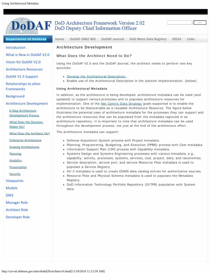
Using Architectural Metadata
http://cio-nii.defense.gov/sites/dodaf20/architect-b.html[11/18/2010 11:12:59 AM]
Home DoDAF-DM2 WG DoDAF Journal DoD Meta Data Registry IDEAS Links
Architecture Development
What Does the Architect Need to Do?
Using the DoDAF V2.0 and the DoDAF Journal, the architect needs to perform two keyactivities:
Develop the Architectural Description.Enable use of the Architectural Description in the solution implementation. (below)
Using Architectural Metadata
In addition, as the architecture is being developed, architecture metadata can be used (andupdated) to support various processes and to populate architecture resources forimplementation. One of the Net-Centric Data Strategy goals supported is to enable thearchitecture to be Discoverable as a reusable Architecture Resource. The figure belowillustrates the potential uses of architecture metadata for the processes they can support andthe architecture resources that can be populated from the metadata captured in anarchitecture repository. It is important to note that architecture metadata can be usedthroughout the development process, not just at the end of the architecture effort.
The architecture metadata can support:
Defense Acquisition System process with Project metadata.Planning, Programming, Budgeting, and Execution (PPBE) process with Cost metadataInformation Support Plan (ISP) process with Capability metadata.Systems Design and Systems Engineering processes with various metadata, e.g.,capability, activity, processes, systems, services, cost, project, data, and taxonomies.Service description, service port, and service Resource Flow metadata is used topopulate a Service Registry.AV-2 metadata is used to create DDMS data catalog entries for authoritative sources.Resource Flow and Physical Schema metadata is used to populate the MetadataRegistry.DoD Information Technology Portfolio Repository (DITPR) population with Systemdata.
Introduction
What is New in DoDAF V2.0
Vision for DoDAF V2.0
Architecture Resources
DoDAF V1.5 Support
Relationships to otherFrameworks
Background
Architecture Development
6-Step ArchitectureDevelopment Process
What Does the Decision-Maker Do?
What Does the Architect Do?
Enterprise Architecture
Scoping Architectures
Planning
Analytics
Presentation
Security
Viewpoints
Models
DM2
Manager Role
Architect Role
Developer Role
Department of Defense
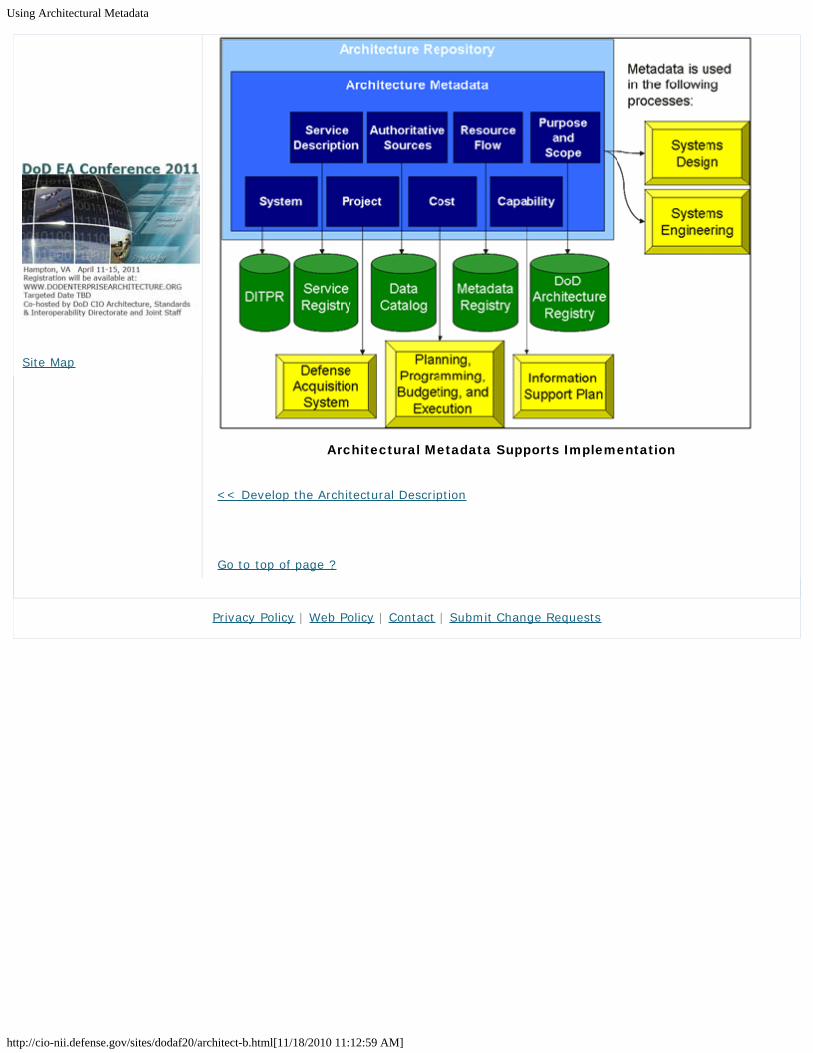
Using Architectural Metadata
http://cio-nii.defense.gov/sites/dodaf20/architect-b.html[11/18/2010 11:12:59 AM]
Architectural Metadata Supports Implementation
<< Develop the Architectural Description
Go to top of page ?
Site Map
Privacy Policy | Web Policy | Contact | Submit Change Requests

Architecture Development - Enterprise Architecture
http://cio-nii.defense.gov/sites/dodaf20/ent_arch.html[11/18/2010 11:14:18 AM]
Home DoDAF-DM2 WG DoDAF Journal DoD Meta Data Registry IDEAS Links
Architecture Development
Enterprise Architecture
“Today, the encouraging coalescence among leaders is that many enterprisesystems have the same architectural approach—although not all express it inthe same way. A similar convergence addresses the kinds of techniques,pattern, and designs that are independent of specific application domains,and that enable effective production of responsive, scalable, flexible, andunifiable enterprise applications.”
Within DoD, Enterprise Architecture (EA) has been seen for many years as providingproduct-oriented insight into a wide range of data, programs, and activities, organizedthrough Communities of Interest (COI). The data-centric approach to DoDAF V2.0 isdesigned to facilitate the reuse and sharing of COI data. Since DoDAF provides theconceptual, logical, and PES but does not otherwise prescribe the configuration of theproduct composition, architects and stakeholders are free to create their views of data thatbest serve their needs.
Introduction and Overview
An Architectural Description is a strategic information asset that describes the current and/ordesired relationships between an organization’s business, mission and managementprocesses, and the supporting infrastructure. Architectural Descriptions define a strategy formanaging change, along with transitional processes needed to evolve the state of a businessor mission to one that is more efficient, effective, current, and capable of providing thoseactions needed to fulfill its goals and objectives. Architectural Descriptions may illustrate anorganization, or a part of it, as it presently exists; any changes desired (whether operationalor technology-driven); and the strategies and projects employed to achieve the desiredtransformation. An Architectural Description also defines principles and goals and setsdirection on issues, such as the promotion of interoperability, intra-, and interagencyinformation sharing, and improved processes, that facilitate key DoD program decisions.
Such support extends beyond details or summaries of operational and systems solutions,and includes program plans, programmatic status reporting, financial and budgetrelationships, and risk management. In addition to detailed views of individual solutions, theframework supports the communication of enterprise-wide views and goals that illustrate thecontext for those solutions, and the interdependencies among the components. Beyond thesolution space, standard mechanisms for communicating program plans, financialinformation, and project status are established so that executives and managers canevaluate and direct their programs.
The DoD EA is an Architectural Description that is an enterprise asset used to assessalignment with the missions of the DoD enterprise, to strengthen customer support, tosupport capability portfolio management (PfM), and to ensure that operational goals andstrategies are met. The DoD EA is shown below. It is comprised of DoD architecture policy,tools, and standards, DoD-level Architectural Descriptions like the DoD InformationEnterprise Architecture (DoD IEA), DoD-level Capability Architectural Descriptions, andComponent Architectural Descriptions. Its purposes are to guide investment portfoliostrategies and decisions, define capability and interoperability requirements, provide accessto Segment architecture information, to establish and enforce standards, guide security and
Introduction
What is New in DoDAF V2.0
Vision for DoDAF V2.0
Architecture Resources
DoDAF V1.5 Support
Relationships to otherFrameworks
Background
Architecture Development
6-Step ArchitectureDevelopment Process
What Does the Decision-Maker Do?
What Does the Architect Do?
Enterprise Architecture
Scoping Architectures
Planning
Analytics
Presentation
Security
Viewpoints
Models
DM2
Manager Role
Architect Role
Developer Role
Department of Defense

Architecture Development - Enterprise Architecture
http://cio-nii.defense.gov/sites/dodaf20/ent_arch.html[11/18/2010 11:14:18 AM]
information assurance requirements across the Department of Defense, and provide a soundbasis for transition from the existing DoD environment to the future. The DoD EA is afederation of Architectural Descriptions with which Solution Architectural Descriptions mustconform. Its content includes but is not limited to rules, standards, services and systemslifecycle information needed to optimize and maintain a process, or part of a process that aself-sufficient organization wants to create and maintain by managing its IT portfolio. TheDoD EA provides a strategy that enables the organization to support its current operationswhile serving as the roadmap for transitioning to its target environment. Transitionprocesses include an organization’s PfM, PPBE, and EA planning processes, along withservices and systems lifecycle methodologies.
Components of the DoD EA
The JCA portfolios describe future, required operational, warfighting, business, and Defenseintelligence capabilities, together with the systems and services required. They provide theorganizing construct for aligning and federating DoD EA content to support the Departmentportfolio management structure. The description of the future DoD operating environmentand associated capability requirements represent the target architecture of the DoD EA.These are time-phased as determined by functional owners and JCA developers.
Migration in a net-centric operating environment from the “As-Is” to the “To-Be” requiresthat the DoD Information Environment Architecture (DoD IEA) and the Net-Centric strategiesact as uniform references for, and guide the transition sequence to ensure that bothoperational/business capabilities and IT capabilities, as required, are properly described.Policy is being developed by the DoD CIO to describe how federation will be used to maturethe DoD EA as well as its relationship to federated, solution Architectural Descriptions.
Transition Planning
As discussed above, one major impetus for creating and using Architectural Descriptions is to
Site Map

Architecture Development - Enterprise Architecture
http://cio-nii.defense.gov/sites/dodaf20/ent_arch.html[11/18/2010 11:14:18 AM]
guide acquisition and development of new enterprises, capabilities and systems orimprovements to existing ones. Earlier versions of DoDAF addressed this need exclusivelyusing “As-Is” and “To-Be” Architectural Descriptions, along with a Systems and/or ServicesTechnology Forecast. The “As-Is” and “To-Be” concepts are time-specific snapshots ofDoDAF views that initially served as the endpoints of a transition process. However, thistransition strategy has several potential pitfalls, to include the difficulty in accuratelyrepresenting the “As-Is” starting point where legacy systems are sometimes poorlydocumented, and processes are largely undefined. There is also the consideration that long-term goals are often very flexible, resulting in flux in the “To-Be” version.
Since the “As-Is” and “To-Be” Architectural Descriptions are time-specific versions of similarsets of data with similar viewpoints, transition planning is able to chart an evolutionary pathfrom the “As-Is” to its corresponding “To-Be” architectural vision given a clearunderstanding of the expected outcomes or objectives through some future (perhapsundefined) future point. It is expected that the To-Be Architectural Descriptions will changeover time as Departmental priorities shift and realign.
Federated Approach to DoD Architecture Management
The Department has adopted a federated approach to distributed architectural datacollection, organization, and management among the Services, Agencies and COIs as itsmeans of developing the DoD Enterprise Architecture, with a virtual rather than physical dataset described through supporting documentation and architectural views. This approachprovides increased flexibility while retaining significant oversight and quality managementservices at the Departmental level. Detailed guidance on the DoD federation approach will becontained in DoDD 8210, “Architecting the DoD Enterprise.”
Tiered Accountability
Tiered Accountability (TA) is the distribution of authority and responsibility to a DoDorganization for an element of the DoD EA. Under TA, DoD is defining and buildingenterprise-wide capabilities that include data standards, business rules, enabling systems,and an associated layer of interfaces for Department, specified segments of the enterprise(e.g., JCA, DoD Components), and Programmatic solutions. Each tier has specific goals, aswell as responsibilities to the tiers above or below them.
Architectural Descriptions are categorized when developed to facilitate alignment (mappingand linking), cataloging, navigating, and searching disparate architecture information in aDoD registry of holdings. All Architectural Descriptions developed by the tiers should befederated, as described in the DoD Federation Strategy.
Alignment in the tiers is required for the DoD EA to be discoverable, shareable, andinteroperable. Architectural Descriptions can also support many goals within the tiers, eachof which may imply specific requirements for structure, content, or level of detail. Alignmentdecisions should balance the interdependence of Architectural Descriptions with the need forlocal flexibility to address local issues. Alignment describes the minimum constraints neededto ensure consistency across architecture levels. Architectural Descriptions often relate atsome ‘touch point’ to other Architectural Descriptions on the same level, level(s) above, orlevel(s) below, and should be discovered and utilized in the development of ArchitecturalDescriptions to ensure that appropriate linkages are created and maintained. The need toplan for them implies that each Architectural Description sharing a touch-point should beavailable to architects on both sides. The DMR for data and the DARS for architectureregistration facilitate the ability to discover and utilize architectural data, with the caveatthat any touch-points within the purview of an established COI adhere to COI guidance.
DoD Architecture Enterprise Services
The next generation of DoD Enterprise Architectures will be constructed by employing a setof DoD Architecture Enterprise Services (DAES) for registering, discovering, aligning,translating, and utilizing architectural data, and derived information to support key DoDdecision processes through implementing the concepts of the DoD Net-Centric Strategies.DAES will be implemented using Web Services, in which specific content and/or functionality

Architecture Development - Enterprise Architecture
http://cio-nii.defense.gov/sites/dodaf20/ent_arch.html[11/18/2010 11:14:18 AM]
is provided by one user for others, many of whom may be unknown to the provider. AnOperational Resource Flow Description (A redesigned Operational Viewpoint 2 (OV-2)DoDAF-described Model) has been retained in DoDAF V2.0 to describe those services thatcan be discovered and subscribed from one or more specific sources and delivered to one ormore known or unknown subscribers.
Registration of architectures, one of the goals of the NCDS , is the first step toward enablingdiscovery of architecture metadata. DAES includes a registration service to register themetadata (through the DMR), and a method to describe the purpose and scope of anArchitectural Description (through DARS). The registration service will enable cataloging ofArchitectural Descriptions in federated repositories, and, once complete, ArchitecturalDescriptions are ‘available’ for discovery. When an Architectural Description is discoverable,it can be aligned to, linked to, or re-used by other Architectural Descriptions. The discoveryservice enables users to execute a federated search for architecture holdings meetingspecified search parameters.
Alignment to the Federal Enterprise Architecture
The OMB established the Federal Enterprise Architecture (FEA) program in 2003 to build acomprehensive business-driven blueprint of the entire Federal Government. OMB’s CircularA-11 requires that Cabinet-level agencies, including the DoD, link their budget submissionsto the FEA, and annually evaluates those submissions through the Enterprise ArchitectureAssessment Program, which establishes an evaluation score for overall agency progress.
The core principles of the FEA program are:
Business-driven approach.Promote collaboration of effort and reuse.Improve efficiency and effectiveness of business operations through the use ofenterprise architecture for the capital investment process.Demonstrate cost savings and cost avoidance through improved core processes, andcross-agency sharing and mutual investment.
DoD leverages the FEA construct and core principles to provide the Department with theenterprise management information it needs to achieve its own strategic transformationgoals and respond to upward reporting requirements of OMB. The primary objective is toimprove DoD performance, using EA, by providing a framework for cross-mission analysisand identification of gaps and redundancies; and by developing transition plans and targetarchitectures that will help move DoD to the net-centric environment.
Several Federal and DoD-specific EA artifacts exist that describe enterprise-levelmanagement information. These include:
The President’s Management Agenda.OMB A-11 Exhibit 300 submissions.OMB FEA Practice Guidance.OMB EA Assessment Guide.OMB FEA Reference Models.DoD EA Reference Model (RM) Taxonomy.DoD EA Consolidated RM.DoD EA Transition Strategy.DoD Segment Architectures.DoD EA Self-Assessment.DoD Architecture Federation Strategy.
These artifacts facilitate the alignment with the FEA, contribute to a broader understandingof architecture alignment, provide a basis for federated Architectural Descriptions, promote amore efficient and effective use of assets, and ultimately lead to better decision-making.
When developing architectures, particularly at the Departmental and Component levels,alignment with the FEA is accomplished by utilizing the Federal Enterprise Architecture-

Architecture Development - Enterprise Architecture
http://cio-nii.defense.gov/sites/dodaf20/ent_arch.html[11/18/2010 11:14:18 AM]
Consolidated Reference Model (FEA-CRM) documents together with DoD documents andreferences as a basis for defining processes, data, services, and technical standards. As anexample, when a process owner determines that an Architectural Description is needed forsome specific purpose, the first references to use are as shown below, as well as otherArchitectural Descriptions above and below the level of the Architectural Description underdevelopment. The DoD-level information is contained in the DoD EA Reference Models, alongwith the implementing guidance, standards, and descriptions of Department-wideinformation that is mapped to the FEA-CRM in accordance with the FEA construct.
References to Architectural Description Development
Resource Description Architecture Use
DetermineProcessesInvolved
DoDAFFEA BusinessReference Model(BRM)
(DoDAF) Determine techniques and notation to beused(FEA BRM) Determine FEA business processes to alignto; use taxonomies in BRM to name processes
Identify andDefine data
DM2 (DM2)FEA Data ReferenceModel (DRM)
(DM2) Data Group and metadata structures(DRM) Existing Government-wide metadata forlinkage to architecture
DocumentArchitecturalDescriptionand EnsureCompliance
DoDAFDoD MetadataRegistry (DMR) DoDArchitectureRegistry System(DARS) ToolsetOMB EA GuidanceFederatedEnterpriseArchitecture-ConsolidatedReference Model(FEA-CRM)OMB EA AssessmentGuide
(DoDAF) provides described models, and guidance oncreating Fit-for-Purpose Views for presentationpurposes(DMR) Provides existing metadata to use inconjunction with DMR to create data required(DARS) provides registration services for architecturediscovery(Toolset) provides automated notation method forcreating views(OMB EA Guidance) provides information on requiredformat and content of EA for OMB 53/300 process(OMB EA Assess. Guide) provides guidance onevaluation of architectures submitted to OMB forreview
PublishArchitecture
DoD ArchitectureFederation StrategyAgency RepositoryDARS
(DoD Fed. Strategy) provides guidance onarchitectural data discovery (Agency Repository)stores EA Data (DARS) Providers EA contactinformation
Go to top of page ?
Privacy Policy | Web Policy | Contact | Submit Change Requests

Architecture Development - Scoping Architectures
http://cio-nii.defense.gov/sites/dodaf20/scoping.html#top[11/18/2010 11:14:36 AM]
Home DoDAF-DM2 WG DoDAF Journal DoD Meta Data Registry IDEAS Links
Scoping Architectures to be "Fit-for-Purpose"
Establishing the scope of an architecture is critical to ensuring that its purpose and use areconsistent with specific project goals and objectives. The term “Fit-for-Purpose” is used inDoDAF to describe an architecture (and its views) that is appropriately focused (i.e.,responds to the stated goals and objectives of process owner, is useful in the decision-making process, and responds to internal and external stakeholder concerns. Meetingintended objectives means those actions that either directly support customer needs orimprove the overall process undergoing change. The architect is the technical expert whotranslates the decision-maker’s requirements into a set of data that can be used byengineers to design possible solutions. At each tier of the DoD, goals and objectives, alongwith corresponding issues that may exist should be addressed according to the establishedscope and purpose, (e.g., Departmental, Capability, SE, and Operational), as shown in thenotional diagram in the figure below.
Establishing the Scope for Architecture Development
Establishing a scope for an architecture effort at any tier is similarly critical in determiningthe architecture boundaries (Purpose and Use expected), along with establishing the datacategories needed for analysis and management decision-making. Scope also defines thekey players whose input, advice, and consensus is needed to successfully architect and
Introduction
What is New in DoDAF V2.0
Vision for DoDAF V2.0
Architecture Resources
DoDAF V1.5 Support
Relationships to otherFrameworks
Background
Architecture Development
6-Step ArchitectureDevelopment Process
What Does the Decision-Maker Do?
What Does the Architect Do?
Enterprise Architecture
Scoping Architectures
Planning
Analytics
Presentation
Security
Viewpoints
Models
DM2
Manager Role
Architect Role
Developer Role
Department of Defense

Architecture Development - Scoping Architectures
http://cio-nii.defense.gov/sites/dodaf20/scoping.html#top[11/18/2010 11:14:36 AM]
implement change (i.e., Stakeholders, both internal and external). Importantly, scope alsodetermines the goals and objectives of the effort, consistent with both boundaries andstakeholders; since goals and objectives define both the purpose for architecture creationand the level of the architecture. Establishing the scope of an effort also determines the levelof complexity for data collection and information presentation.
Architecture development also requires an understanding of external requirements that mayinfluence architecture creation. An architecture developed for an internal agency purpose stillneeds to be mappable, and consistent with, higher level architectures, and mappable to theDoD EA. For some architecture developments, consideration must be given in data collectionand graphical presentation to satisfaction of other external requirements, such as upwardreporting and submission of architectural data and models for program review, fundingapproval, or budget review due to the sensitivity or dollar value of the proposed solution.This site contains guidance on data collection for specific views required by instruction,regulation, or other regulatory guidance (i.e., Exhibit 53, or Exhibit 300 submissions; OMBSegment architecture reviews, or interoperability requirements).
Architecture scoping must facilitate alignment with, and support the decision-making processand ultimately mission outcomes and objectives as shown in the figure below. Architecturaldata and supporting views, created from organizing raw data into useful information, andcollected into a useful viewpoint, should enable domain experts, program managers, anddecision makers to utilize the architecture to locate, identify, and resolve definitions,properties, facts, constraints, inferences, and issues, both within and across architecturalboundaries that are redundant, conflicting, missing, and/or obsolete. DoDAF V2.0 providesthe flexibility to develop both Fit-for-Purpose Views (User-developed Views) and views fromDoDAF-described Models to maximize the capability for decision-making at all levels. Thefigure below shows how the development of architectures supports the management decisionprocess. In this case, the example shows how an architecture and the use of it in analysiscan facilitate the ability to determine and/or validate mission outcome.
Analysis also uncovers the effect and impact of change (“what if”) when something isredefined, redeployed, deleted, moved, delayed, accelerated, or no longer funded. Having adisciplined process for architecture development in support of analytics will produce qualityresults, not be prone to misinterpretations, and therefore, be of high value to decisionmakers and mission outcomes.
Site Map

Architecture Development - Scoping Architectures
http://cio-nii.defense.gov/sites/dodaf20/scoping.html#top[11/18/2010 11:14:36 AM]
Mission Outcomes Supported by Architectures
Go to top of page ?
Privacy Policy | Web Policy | Contact | Submit Change Requests

Architecture Development - Architecture Planning
http://cio-nii.defense.gov/sites/dodaf20/planning.html#top[11/18/2010 11:14:55 AM]
Home DoDAF-DM2 WG DoDAF Journal DoD Meta Data Registry IDEAS Links
Architecture Development
Architecture Planning
Defining the Enterprise
In a generic sense, an enterprise is any collection of organizations that has a common set ofgoals and/or a single bottom line. An enterprise, by that definition, can encompass a MilitaryDepartment, DoD as a whole, a division within an organization, an organization in a singlelocation, or a chain of geographically distant organizations linked by a common managementor purpose. An enterprise today is often thought of as an extended enterprise wherepartners, suppliers, customers, along with their activities and supporting systems, areincluded in the Architectural Description.
Government agencies may comprise multiple enterprises, and there may be separateenterprise architecture, or Architectural Description projects. However, the projects oftenhave much in common about the execution of process activities and their supportinginformation systems, and they are all linked an enterprise architecture. Architecturaldescription development in conjunction with the use of a common architecture framework,which describes the common elements of Architectural Descriptions, lends additional value tothe effort, and provides a basis for the development of an architecture repository for theintegration and reuse of models, designs, and baseline data.
The Enterprise-level Architecture
Enterprise-level Architectural Descriptions in DoD are generally created under theresponsibility and authority of a senior-level official within the Department, Component,Organization, Agency, or the program office responsible for development of JCAs. As anenterprise-level effort, it is expected that all of the major processes are documented anddescribed, even if a specific project involves only a more limited subset of processes oractivities. That way, subsequent Architectural Description efforts can build on previous effortsto ensure the integration and extension of the enterprise is not compromised. Enterprise-level Architectural Descriptions usually exhibit breadth rather than depth. Since thisArchitectural Description is the 'capstone', or highest level of an Architectural Description, onwhich others will build, it is especially important that processes, which relate to each other,either through interaction of activities, or the use of data by internal and externalstakeholders, are identified or documented.
Solution Architectures
The solution-architecture is scoped to include all major activities that are associated with anidentified solution for a capability gap in response to a specific requirement. This solutionmay contain links to one or programs which require the data and/or outputs produced by thespecified the solution identified to fill a specified gap.
Architecture Management
Architectural Descriptions are designed to describe the data on an organization orprogram/capability that will support continuing managing decision-making over time.Creation of Architectural Descriptions and their management follow an established lifecyclethat is similar to those other resources that have well-described lifecycles. OMB Circular A-130 describes the lifecycle as:
Develop.
Introduction
What is New in DoDAF V2.0
Vision for DoDAF V2.0
Architecture Resources
DoDAF V1.5 Support
Relationships to otherFrameworks
Background
Architecture Development
6-Step ArchitectureDevelopment Process
What Does the Decision-Maker Do?
What Does the Architect Do?
Enterprise Architecture
Scoping Architectures
Planning
Detailed Planning
Approaches
Analytics
Presentation
Security
Viewpoints
Models
DM2
Manager Role
Architect Role
Developer Role
Department of Defense

Architecture Development - Architecture Planning
http://cio-nii.defense.gov/sites/dodaf20/planning.html#top[11/18/2010 11:14:55 AM]
Use.Maintain.
These phases recognize discreet actions that occur at various times, all designed to ensurethat architectural data can be collected and later reused for management decision-makingand reporting.
Architecture Development
Architectural Descriptions are developed to represent either the state of an activity at aspecified time (i.e., baseline architecture) or the results of change in an activity that willoccur over some future time (i.e., "To-Be" or future architecture). Enterprise architectures(usually with Departmental, Capability, Segment, or Component content) are initially createdto create a common context needed to understand the organization and operations of high-level processes under their control.
Solution Architectural Descriptions collect data that is specific to their program or capability,and data necessary to link to both the higher-level Architectural Descriptions with whichthey share common parentage, and any lower-level Architectural Descriptions, whichdescribe in more detail particular aspects of the program or JCA.
Visualization of data provides a unique perspective of data from the viewpoint needed fordecision-making. That may be a commander/director, action officer, system developer, dataadministrator, user, or anyone else executing some part of the architected process. Morediscussion of data collection and visualization is contained in the Logical data Model.
Architecture Lifecycle and Architecture Governance
Architectural Description development is only one phase of an overall architecture lifecycle,similar to other process maturity and change lifecycles. One such lifecycle, the ArchitectureGovernance, Implementation, and Maturity Cycle, shown in the figure below, is described indetail in the DoDAF Journal. This lifecycle relies on the commonly used Plan-Do-Check-Act(PDCA) governance method.
Plan, Do, Check, and Act (PDCA) Cycle
Architecture Utilization
Site Map

Architecture Development - Architecture Planning
http://cio-nii.defense.gov/sites/dodaf20/planning.html#top[11/18/2010 11:14:55 AM]
The ultimate success of an Architectural Description effort lies in the ability to usearchitectural-related data to support decisions for change within the organization. WhileArchitectural Description development is generally accomplished as a project, accomplishedthrough a team trained for that purpose, the results of the Architectural Descriptiondevelopment, to be effective over the longer term, need to be adopted as the common,normal mode of performing the organization's business.
The enterprise architecture, as a corporate asset, should be managed like any other asset,and reinforced by management as a key part of the formal program that results in decision-making. Achieving that level of acceptance occurs only when Architectural Descriptions arecreated that reflect reality (e.g., baseline), or planned change/growth (e.g., "To-Be", ortarget).
Successful execution of the EA development process in an agency-wide endeavor requiresmanagement direction and support, allocation of resources, continuity, and coordination.Creating an EA program calls for sustained leadership and strong commitment, buy-in by theagency head, senior leadership, and early designation of a lead architect. These leaders andthe supporting EA Team are the first level of support for institutionalizing the results of theeffort.
When architectural data and views are constructed and organized in a way that they areunderstood, accepted, and utilized in daily activities, they facilitate decision-making. Toachieve optimal success, architectural views and data must meet standards that facilitatereuse by others whose activities border on, or replicate activities, services and systemsalready documented by architectural data and products. To that end, data collection mustadhere to the standards set by the COI, or other recognized authority so that the data canbe registered for, and used by others.
Architecture Maintenance
Changes in an organization supported by Architectural Description development will achieveinstitutionalization only when the senior leadership agrees with, supports, encourages,reinforces, and adopts the results of the Architectural Description effort. Ideally, a memberof the Senior Leadership Team should be designated as the 'champion' of the change effort,and should work with the process owner to ensure that institutionalization occurs Employees,who actually perform the daily activities described in the Architectural Description, must berepresented in the Architecture Development Team and contribute to the overall datacollection and view creation.
Architecture Compliance Reviews
Architectural description compliance reviews are a key part of the validation and verification(V&V) process ongoing throughout the Architectural Description development effort. Acompliance review is a type of review that analyzes whether Architectural Descriptiondevelopers are progressing according to the specifications and requirements developed forthe Architectural Description effort by the process owner. The goals of an architecturecompliance review include:
Identifying errors in the Architectural Description early to reduce the cost and risk ofchanges required later in the project. These error-catching actions will reduce cost andschedule slips, and will quickly realize business objectives.Ensuring the application of best practices to Architectural Descriptions work(Development, use, and maintenance).Providing an overview of the compliance of architecture to mandated enterprisestandards.Identifying and communicating significant architectural gaps to supplier and serviceproviders.Communicating to management the status of technical readiness of the project.
Utilization of architecture compliance reviews as an integral part of the development processensures that utilization of architectural data and views later will be in conformance with

Architecture Development - Architecture Planning
http://cio-nii.defense.gov/sites/dodaf20/planning.html#top[11/18/2010 11:14:55 AM]
applicable requirements. A more in-depth discussion of the compliance review process iscontained in the DoDAF Journal.
OMB Architecture Assessment. The OMB requires departments and independent agenciesto submit a self-assessment of their enterprise architecture programs in February of eachyear. For DoD, this applies at the Department level. The self-assessment is performed inthree EA capability areas: completion of the EA, use of the EA and results, and utilization ofthe OMB Federal Enterprise Architecture program EA Assessment Framework. Specifics of theDoD/OMB architecture self-assessment are described in the DoDAF Journal.
GAO Architecture Assessment. The Government Accountability Office (GAO) periodicallyrequires all departments and independent agencies to submit a self-assessment of thematurity of the management of their EA programs. In addition, GAO may perform their ownreview and assessment of architecture efforts associated with large-scale programs. Incertain cases, GAO expects an agency to establish an independent quality assurance processfor a large-scale architecture to determine whether it meets quality criteria such as thoseidentified earlier in this page. Specifics of the DoD/GAO architecture self-assessment aredescribed in the DoDAF Journal. The Enterprise Architecture Management MaturityFramework (EAMMF) can also be used for this purpose.
User Support
User support is the service that each enterprise unit provides its users, both internally andexternally to the enterprise, as described in the architectural data and views.
Training
It is the responsibility of agency executive management to institutionalize the controlstructures for the EA process, as well as for the agency Capital Planning & Investment (CPIC)and Shelf Life Code (SLC) processes. For each decision-making body, all members should betrained, as appropriate, in the EA, the EA process, the relationship of the EA to the Agency'smission, DoDAF, and the FEA. Specific training, at various levels of detail, should be tailoredto the architecture role of the personnel.
Architecture development training for team members is often provided by the team leaderand Chief Architect during the course of team operations. Training for team membersincludes sessions on group interactions, toolset operations, data collection, and creation ofmodels and views.
Communications Planning
Communication management is the formal and informal process of conducting or supervisingthe exchange of information to all stakeholders of enterprise architecture. Communicationplanning is the process of ensuring that the dissemination, management, and control ofcritical stakeholder information is planned and executed in an efficient and effective manner.
The purpose of communications planning is to (1) keep senior executives and business unitscontinually informed, and (2) to disseminate EA information to management teams. TheChief Architect and support staff defines a marketing and communications plan consisting of:
Constituencies.Level of detail.Means of communication.Participant feedback.Schedule for marketing efforts.Method of evaluating progress and buy-in.
The CIO's role is to interpret the Agency Head's vision, and recognize innovative ideas (e.g.,the creation of a digital government) that can become key drivers in the EA strategy andplan. In turn, the Chief Architect is the primary technical communicator with the communitiesof interest involved in an Architectural Description effort.
At the Process Owner level, the communications plan is similar to that described above forthe CIO. As with the CIO at the enterprise, the process owner is the manager of Architectural

Architecture Development - Architecture Planning
http://cio-nii.defense.gov/sites/dodaf20/planning.html#top[11/18/2010 11:14:55 AM]
Description efforts, supported by an architect and development team. The process ownermust clearly define the purpose and scope of an Architectural Description effort (i.e., "Fit-for-Purpose") and communicate those goals and objectives for the Architectural Descriptioneffort to the architect and team. In turn, as development of the Architectural Descriptionprogresses, the architect provides feedback to the process owner, participates in validationand verification activities, and provides revisions, as required to the original developmentplan.
Quality Planning
Quality management is the process of organizing activities involving the determination ofquality requirements, establishing quality policies, objectives, performance measures(metrics), and responsibilities, and ensuring that these policies, objectives, and measures(metrics) will satisfy the needs within the enterprise. The quality management systemexecutes policies, procedures, and quality planning processes, along with quality assurance,quality control processes, and continuous process improvement activities to improve theoverall health and capability of the enterprise. The primary input into the qualitymanagement process is quality planning.
Quality planning for Architectural Description development identifies which quality standardsare relevant to creation of the Architectural Description and determines how to satisfy them.Quality requirements are stated in the Project Scope Statement, further defined in theProgram Management Plan and other guidance, such as that provided by the methodologybeing applied to the development effort. Guidance also includes other enterpriseenvironmental factors, such as Governmental agency regulations, rules, standards, andguidelines specific to the application area. Information needed during quality planning isgenerally collected during Architectural Description development, and represented inarchitectural data and views as controls, resources, inputs, and outputs, as appropriate. Amore comprehensive discussion of quality planning is provided online in the DoDAF Journal.
Risk Management
Risk management is the act or practice of dealing with risk. It includes planning for risk,assessing risk issues, developing risk handling strategies, and monitoring risk to determinehow they have changed. Risk management planning is the process of deciding how toapproach and conduct the risk management activities for the enterprise, program, andprojects.
Architectural-based risk assessment is a risk management process that identifies flaws inArchitectural Description and determines risks to business information assets that resultfrom those flaws. Through the process of architectural risk assessment, risks are identifiedand prioritized based on their impact to the business; mitigations for those risks aredeveloped and implemented; and the Architectural Description is reassessed to determinethe efficacy of the mitigations.
Risk management planning should be initiated early during development of the scope for theArchitectural Description effort. Mitigation of risk is crucial to success of the overall effort.Inputs to the risk management planning process include a review of existing enterpriseenvironmental factors, organizational process assets, the proposed scope statement, and theprogram management plan. Enterprise environmental factors are the attitudes toward riskand the risk tolerance of the organizations and people involved in the organization that exertinfluence over change. Risk attitudes and tolerances may be expressed in policy statementsor revealed in actions. Organizational process assets are tools and techniques, whichnormally predefine organizational approaches to risk management such as established riskcategories, common definitions of concepts and terms, standard templates, roles andresponsibilities, and authority levels for decision-making.
A comprehensive discussion of Risk management can be found online in the DoDAF Journal.
Go to top of page ?

Architecture Development - Architecture Planning
http://cio-nii.defense.gov/sites/dodaf20/planning.html#top[11/18/2010 11:14:55 AM]
Privacy Policy | Web Policy | Contact | Submit Change Requests

Architecture Development - Detailed Planning
http://cio-nii.defense.gov/sites/dodaf20/detailed.html[11/18/2010 11:15:23 AM]
Home DoDAF-DM2 WG DoDAF Journal DoD Meta Data Registry IDEAS Links
Architecture Development
Detailed Planning
Planning an Architectural Description effort involves more than selection of a method fordevelopment. The Architectural Description effort starts with the identification of arequirement, problem, or desired change by the process owner – the senior officialresponsible for the overall operation of the functional, tactical, component or JCA. Theprocess owner selects a team leader and team members who will actively participate in theArchitectural Description effort. That team may have a varying membership, generallyincluding an enterprise architect, and subject matter experts in the process area undergoinganalysis and potential change, and will refine the process owner’s vision and/or initialrequirement into a project through development of an appropriate Architectural Description.
Managers and decision-makers are generally not technicians or information architects. Theydo, however, have a vital part in the decisions that need to be made early in the planningprocess to define the types of views they need to support their involvement in the decision-making process. Organizations differ in the type of presentation materials they prefer (i.e.,dashboards, charts, tables) and these preferences need to be accommodated duringArchitectural Description development. Toolsets should be selected that have the capabilityto provide these management views and products, along with the ability to collect andorganize data consistent with the DM2 to facilitate reuse. A detailed discussion of toolsetrequirements and capabilities is contained in the DoDAF Journal.
Go to top of page ?
Introduction
What is New in DoDAF V2.0
Vision for DoDAF V2.0
Architecture Resources
DoDAF V1.5 Support
Relationships to otherFrameworks
Background
Architecture Development
6-Step ArchitectureDevelopment Process
What Does the Decision-Maker Do?
What Does the Architect Do?
Enterprise Architecture
Scoping Architectures
Planning
Detailed Planning
Approaches
Analytics
Presentation
Security
Viewpoints
Models
DM2
Manager Role
Architect Role
Developer Role
Department of Defense

Architecture Development - Detailed Planning
http://cio-nii.defense.gov/sites/dodaf20/detailed.html[11/18/2010 11:15:23 AM]
Site Map
Privacy Policy | Web Policy | Contact | Submit Change Requests

Approaches to Architecture Development
http://cio-nii.defense.gov/sites/dodaf20/approaches.html[11/18/2010 11:15:46 AM]
Home DoDAF-DM2 WG DoDAF Journal DoD Meta Data Registry IDEAS Links
Architecture Development
Approaches to Architecture Development
Several methodologies, with supporting tools, techniques, and notations (i.e., a set ofwritten symbols used to represent something such as activity, decisions, systems,applications, interfaces) exist for developing Architectural Descriptions. While DoDAF doesnot promote a specific approach, the DoDAF provides the rules, standard entities, andrelationships for developing Architectural Descriptions in a semantically consistent andinteroperable fashion. The DoDAF V2.0 CDM and LDM, along with the PES, have beendesigned to facilitate adoption of DoDAF by a wide range of toolsets and techniques. TheDM2 should be used as the principal reference for creating the data structures in toolsets toensure both interoperability and reuse capabilities. An achievable level of commonalityamong the notations is possible when basing architecture development on the DoDAF V2.0CDM and LDM.
NOTE: Several commercial toolsets that are commonly used to develop architectureviews still use the terms ‘model’ of ‘diagram’ to describe those views. Within this chapter,we continue to use the terms ‘model’ and ‘diagram’, as they are used by toolset vendors,to avoid confusion. However, a model or diagram created by a toolset, using anappropriate notation, and included in a set of views in a DoD architecture should beunderstood as a ‘view’ within DoDAF.
The two most common techniques—the SADT Approach and the OOAD Approach—arediscussed briefly below. Examples of the notation supporting these techniques are presentedin examples contained within this site. Either of these techniques can be used with themethodology described above, or by others, such as MODAF, NAF, TOGAF, or otherGovernment or commercial offerings.
Structured Technique Overview. Architectural Descriptions developed under a structuredanalysis-driven approach are process-oriented and characterized by hierarchical processdecomposition. Historically, structured models generally used in DoD originated from theIntegration Definition Language developed by the U.S. Air Force, and later used to developthe Integration Definition for Activity Modeling (IDEF0) [IDEF0 1993] Standards and theFederal Information Processing Standard (FIPS) published by the National Institutes forStandards & Technology (NIST). This technique evolved from an earlier, also process-drivenapproach, SADT, developed for the U.S. Air Force Materiel Command. More recently,architecture development using structured methods has also included those utilizing theBPMN, developed by the Business Process Management Initiative, and currently managed bythe Object Management Group (OMG).
Process Data Flow. A process flow diagram (PFD) is a graphical representation of the flowof data through a process. With a process flow diagram, users are able to visualize how theprocess will operate, what the process will accomplish, and how the process is executednormally. Process flow diagrams can be used to provide the end user with a physical idea ofthe resulting actions that occur on data input, and how their actions ultimately have aneffect upon the structure of the whole process. Process flow diagrams also define desired orrequired system-level functions—the level and type of automation desired to improve thetime, efficiency, and results of executing a process.
Introduction
What is New in DoDAF V2.0
Vision for DoDAF V2.0
Architecture Resources
DoDAF V1.5 Support
Relationships to otherFrameworks
Background
Architecture Development
6-Step ArchitectureDevelopment Process
What Does the Decision-Maker Do?
What Does the Architect Do?
Enterprise Architecture
Scoping Architectures
Planning
Detailed Planning
Approaches
Analytics
Presentation
Security
Viewpoints
Models
DM2
Manager Role
Architect Role
Developer Role
Department of Defense

Approaches to Architecture Development
http://cio-nii.defense.gov/sites/dodaf20/approaches.html[11/18/2010 11:15:46 AM]
Process Task-Dependency Diagram. Process Task Dependency (PTD) Diagrams lay outclearly the step-by-step flow of a process by tracking the flow of material, information or aservice through all its steps in a logical or required order. The PTD diagram assists anunfamiliar audience to picture the steps of a process and clarifies misconceptions about howthe process actually operates, while providing a reference for the handling of correctiveaction or process improvement. Task-sequence notations work especially well foruninterruptible processes, meaning a set of steps that exhibits clear dependencies, doesn’texecute until explicitly triggered, and normally continues until it achieves a clear exitcriterion. Such processes are generally low-level and detailed, and useful for:
Defining detailed performance measures (metrics) and measures capture.Establishing an information base for executable architecture/process simulation.Defining automation functional requirements.
Entity-Relation Model. The Entity-Relation Model describes the structure of an architecturedomain’s system data types and the business process rules that govern the system data. Itprovides a definition of architectural domain data types, their attributes or characteristics,and their interrelationships.
Object-Oriented Technique Overview. Object-oriented architectural views are createdutilizing the Unified Modeling Language (UML) architecture technique and notation, togetherwith the DoDAF logical and PES data structures. This technique describes the operationalneed, places data (objects, or ‘performers’ in the DoDAF data structure) in the context of itsuse, and provides a traceable foundation for system and software design. It is based on theconcepts of data abstraction and inheritance from a service-oriented view. The object-oriented technique provides an orderly arrangement of the parts of the business organizationand includes a style and method of design through its highly developed notation style.
Process – Activity Diagram, Object-Sequence Diagram. An activity diagram isfrequently used in conjunction with a process flow diagram that describes the sequence andother attributes (i.e., timing) of the activities. A process flow diagram further captures theprecedence and causality relations between situations and events. In object modeling,activity diagrams address the dynamic view of the system. They are especially important inmodeling the function of a system and emphasize the flow of control among objects. Anobject diagram shows a set of objects (i.e., performers) and their relationships. Objectdiagrams represent static snapshots of instances of things found in class diagrams.
Data – Object Class Diagram. Class diagrams offer all the UML elements needed toproduce entity-relationship diagrams. Class diagrams consist of classes, interfaces,collaborations, dependency, generalization, association, and realization relationships. Theattributes of these classes can be expanded to include associations and cardinality [Booch,1999]. In terms of support to DoDAF V1.5, classes that appear in an OV-7 (The DIV-3 inDoDAF V2.0) class diagram correlate to OV-3 information elements and OV-5 inputs andoutputs. The OV-7 class diagram is a separate diagram from the class diagrams that may bedeveloped for other products.
System (Component, Package, Deployment) Diagram
DoDAF V2.0 provides extensive architectural support for the SE process. As the process ofdeveloping the system architecture moves from the high-level concept (e.g., systeminterface description, system overview diagram) to more detailed views, it becomes useful tocreate multiple models so that specialized views (“Fit-for-Purpose”) of the ArchitecturalDescription can be depicted. Three important diagrams (Fit-for-Purpose Views) are 1) theComponent Model, which focuses on functional features of the system; 2) the PackageDiagram, which focuses on grouping of components for specific purposes; and 3) theDeployment/Operational Model, which focuses on the physical runtime infrastructure on
Site Map
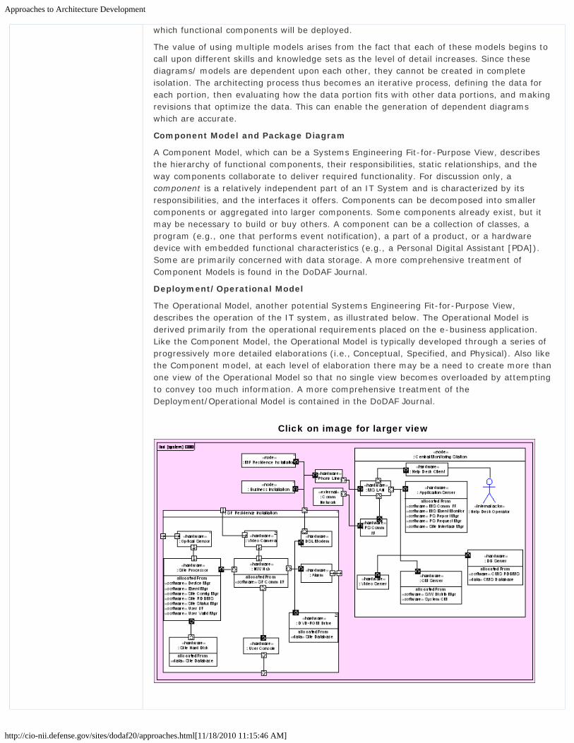
Approaches to Architecture Development
http://cio-nii.defense.gov/sites/dodaf20/approaches.html[11/18/2010 11:15:46 AM]
which functional components will be deployed.
The value of using multiple models arises from the fact that each of these models begins tocall upon different skills and knowledge sets as the level of detail increases. Since thesediagrams/ models are dependent upon each other, they cannot be created in completeisolation. The architecting process thus becomes an iterative process, defining the data foreach portion, then evaluating how the data portion fits with other data portions, and makingrevisions that optimize the data. This can enable the generation of dependent diagramswhich are accurate.
Component Model and Package Diagram
A Component Model, which can be a Systems Engineering Fit-for-Purpose View, describesthe hierarchy of functional components, their responsibilities, static relationships, and theway components collaborate to deliver required functionality. For discussion only, acomponent is a relatively independent part of an IT System and is characterized by itsresponsibilities, and the interfaces it offers. Components can be decomposed into smallercomponents or aggregated into larger components. Some components already exist, but itmay be necessary to build or buy others. A component can be a collection of classes, aprogram (e.g., one that performs event notification), a part of a product, or a hardwaredevice with embedded functional characteristics (e.g., a Personal Digital Assistant [PDA]).Some are primarily concerned with data storage. A more comprehensive treatment ofComponent Models is found in the DoDAF Journal.
Deployment/Operational Model
The Operational Model, another potential Systems Engineering Fit-for-Purpose View,describes the operation of the IT system, as illustrated below. The Operational Model isderived primarily from the operational requirements placed on the e-business application.Like the Component Model, the Operational Model is typically developed through a series ofprogressively more detailed elaborations (i.e., Conceptual, Specified, and Physical). Also likethe Component model, at each level of elaboration there may be a need to create more thanone view of the Operational Model so that no single view becomes overloaded by attemptingto convey too much information. A more comprehensive treatment of theDeployment/Operational Model is contained in the DoDAF Journal.
Click on image for larger view

Approaches to Architecture Development
http://cio-nii.defense.gov/sites/dodaf20/approaches.html[11/18/2010 11:15:46 AM]
Go to top of page ?
Privacy Policy | Web Policy | Contact | Submit Change Requests

Architecture Development - Analytics
http://cio-nii.defense.gov/sites/dodaf20/analytics.html[11/18/2010 11:16:05 AM]
Home DoDAF-DM2 WG DoDAF Journal DoD Meta Data Registry IDEAS Links
Architecture Development
Architecture-Based Analytics
Architecture-based analytics the process of doing analysis with and on architectural data. Itincludes all of the processes that transform architectural data into useful information insupport of the decision making process. Various types of analysis are described below (staticvs. dynamic), along with descriptions of desirable characteristics for the overall architecturaldata set needed for successful and accurate analysis capability. Architectural Descriptions arean ideal construct to use in decision-making, provided they represent the most current andaccurate information about a program or mission requirement.
Analytics Context
DoDAF V2.0 has been designed to facilitate the collection of relevant data employingquantitative, repeatable, analytical processes to support decisions at all levels of anenterprise. Architectural views (formerly “products”) are no longer the end goal, but aredescribed solely to facilitate useful to the underlying information. All views are tailorable.Data completeness of the data schema are more critical than the view chosen by a particularuser. Analytics, properly conducted, represent a powerful tool for the decision-maker,ensuring that the most appropriate, current, and valid data is used to support decisions.
Analytics are central to successful decision-making. Analysis defines and describes potentialcourses of action (i.e., alternatives) that can be considered when making a mission orprogram decision.
The Analytics Process
Architecture development is an iterative process. Analyses developed on the basis ofsignificant architectural data remain valid only as long as the processes and information donot change, and management decision-making remains focused on the same problem forwhich the architectural data was collected. When any of these assumptions is updated,previous analyses should be reviewed to determine if the previous analysis needs to beredone. Such examination needs to be recognized as natural in an environment where
Introduction
What is New in DoDAF V2.0
Vision for DoDAF V2.0
Architecture Resources
DoDAF V1.5 Support
Relationships to otherFrameworks
Background
Architecture Development
6-Step ArchitectureDevelopment Process
What Does the Decision-Maker Do?
What Does the Architect Do?
Enterprise Architecture
Scoping Architectures
Planning
Analytics
Presentation
Security
Viewpoints
Models
DM2
Manager Role
Architect Role
Developer Role
Department of Defense

Architecture Development - Analytics
http://cio-nii.defense.gov/sites/dodaf20/analytics.html[11/18/2010 11:16:05 AM]
Iterative Approach
program direction and priorities are constantly in flux.
The need for iterative analyses pointstowards tool-assisted and tool-supportedanalyses whenever possible. Processsteps, such as re-running analyses, thatare difficult or time consuming toperform will not likely be performedunless they are automated. The iterativeapproach enables ArchitecturalDescriptions to achieve incremental goalsearly, and throughout the architecturelifecycle.
Types of Architecture Analysis
There are two categories of analyticalactivity. These are:
Static Analyses: Those analyses, which are based on making a value judgments,based on data extracted from the Architectural Description. Analysis of weatherpatterns and measurements for the last 50 years to determine trends and correlationsis an example of static analyses.Dynamic Analyses: Those analyses, which are based on running an executable versionof the architectural data to observe the overall behavior of the model. Theconstruction and execution of weather prediction model to determine possible futureweather trends is an example of dynamic analysis.
Examples of Analytics
Analytic methods can be applied to the many aspects of the architecting process. Examplesof analytical support can be found within DOTMLPF, as shown below. DOTMLPF analysisleads to better definition of a warfighting capability by being able to anticipate its effects andassess the impact of change on the domains within which the change will be deployed.
DOTMLPF domains map to DM2 CDM concepts with the following analytical support activities:
DOTMLPFDomains
DoDAF Conceptual DataModel concepts
Analytical Support Activities
Doctrine Functions, Performers,Assets, Locations
Examine Tactics, Techniques, andProcedures
Organization Performers, Org Units Examine organizational structure
Training Functions, Performers,Assets
Train personnel on their activities and thesystems they use
Materiel Functions, Material, Data,Information, Location,Assets, Performers
Examine materiel solutions – a newsystem?
Leadership Org Units, Performers, Examine leadership issues
Site Map

Architecture Development - Analytics
http://cio-nii.defense.gov/sites/dodaf20/analytics.html[11/18/2010 11:16:05 AM]
Assets
Personnel Performers Examine personnel solutions – newpersonnel or personnel with betterqualifications
Facilities Locations Examine fixing, building, or modifyingfacilities
The list above is potentially analytical activities that relate to DM2 CDM concepts potentiallyapplicable to DOTMLPF domains. As more demands are placed on architecture, the flexibilityinherent in DoDAF will encourage further innovation from architects and from tool vendorsalike.
Principles of Architecture Analytics
The five key foundational principles of architecture analytics are described below:
Information Consistency
Information consistency means that data (and the information derived from it) within anArchitectural Description is consistent with an overarching metadata structure (called a‘schema’). In addition to adhering to the explicit syntax (naming rules) of the schema, dataalso needs to be consistent with any additional rules specified by the project. Informationconsistency is usually checked to some degree by commercial architecture tools; additionalchecking should be conducted to help assure a consistent architectural view.
Information consistency also refers to whether the data in one area of the ArchitecturalDescription agrees with the data in another area. For instance, if a specific Activity isassigned to a role in one place, yet in another portion of the Architectural Description, thatrole is shown as not having responsibility for that activity, this would be an informationinconsistency.
Data Completeness
Data completeness refers to the requirement that all necessary attributes of each dataelement be specified. For example, a set of system functions where only some of thefunctions have associated textual descriptions would not be data complete. Datacompleteness also refers to the property of having all necessary data to perform certainanalyses, view generation, and/or simulations or executable architectures.
Transformation
Many decisions require the use of data contained in datasets created by different tools.Utilizing the data for analysis may require a transformation of the data into an alternativestructure, where it may be accessed by another tool. Transformation allows the intellectualcapital invested in the Architectural Description to reach beyond the set of tools used tocreate it.
Iteration
Analysis needs to support an iterative architecture refinement and decision process. Analysisthat takes too long in any iteration will quickly become irrelevant. Rather, small iterativesteps or modules should be created that will produce reliable, trusted results.
Lack of Ambiguity
An architectural dataset must make clear the meaning of each element defined within it. Ifthere are semantically variable architectural constructs, they cannot be accurately analyzed.This limits the scope and effectiveness of analytics and the usefulness of the architectureitself. Semantic specificity is essential to gain the full benefits of analyses.
Go to top of page ?

Architecture Development - Analytics
http://cio-nii.defense.gov/sites/dodaf20/analytics.html[11/18/2010 11:16:05 AM]
Privacy Policy | Web Policy | Contact | Submit Change Requests

Architecture Presentation Techniques
http://cio-nii.defense.gov/sites/dodaf20/presentation.html[11/18/2010 11:16:36 AM]
Home DoDAF-DM2 WG DoDAF Journal DoD Meta Data Registry IDEAS Links
Architecture Development
Architecture Presentation Techniques
While information is the lifeblood of enterprise architecture, it can be overwhelming todecision makers when presented in a raw format. Likewise, the structured methodology ofmodeling enterprise architecture information is both necessary and useful for creatingArchitectural Descriptions that can be shared between organizations. However, many of the'traditional' architecture products are unwieldy because of their format and are useful only totrained architects. Many organizations develop a mandated architecture but make itexpensive shelf-ware instead of using it to communicate important, accurate, and relevantinformation to the stakeholders who need it. Architects must be able to communicatearchitectural information in a meaningful way to process owners and other stakeholders, orthe discipline of enterprise architecture will soon meet an untimely demise.
The results of architectural-related data collection need to be presentable to non-technicalsenior executives and managers at all levels. Many managers are skilled decision-makers,but have not had technical training in Architectural Description development. SinceArchitectural Description development efforts are designed to provide input to the decision-making process, representation of data needed is a logical extension of the overall process.This section describes these representations (architects call them models or views).
Overview
Effective presentation of business information is necessary for architects to tell the story ofthe architectural data with stakeholders. Since the purpose of the architecture discipline is tocollect and store all relevant information about an enterprise, or some specific part of theenterprise, it can reasonably be assumed that the majority of information needed by anorganization's decision makers is contained somewhere in the architectural data. Many of theexisting architecture methods are valuable for organizing architectural information, but lessvaluable for communicating that information to stakeholders. Presentation views are alwaysdependent on the quality of the architectural information that is collected through the rigorof architecture methods. As the figure below illustrates, presentation techniques pull fromthe architectural information store and display the data in a variety of meaningful ways tostakeholders.
Introduction
What is New in DoDAF V2.0
Vision for DoDAF V2.0
Architecture Resources
DoDAF V1.5 Support
Relationships to otherFrameworks
Background
Architecture Development
6-Step ArchitectureDevelopment Process
What Does the Decision-Maker Do?
What Does the Architect Do?
Enterprise Architecture
Scoping Architectures
Planning
Analytics
Presentation
Overview
Choosing an AppropriatePresentation Technique
Composite Views
Dashboard Views
Fusion Views
Graphics View
Reference Models
Security
Viewpoints
Models
DM2
Manager Role
Department of Defense

Architecture Presentation Techniques
http://cio-nii.defense.gov/sites/dodaf20/presentation.html[11/18/2010 11:16:36 AM]
Presentation Techniques
The presentation techniques and best practices described here were developed based on theidea that business information, captured both internally and externally to an organization'sarchitecture in support of common user requirements, can be displayed in a way thatenhances clarity and understanding, and facilitates decision-making. That often meanscomplex technical information has to be 'translated' into a form for presentation that isuseful to management. An 'Information Bridge', as shown in the figure below, is the linkbetween the architect and management. The bridge provides the means to take technicalinformation, and recast that information in graphical or textual terms that consistent with theculture of the organization.
The Information Bridge
DoDAF V1.0 and V1.5 defined a set of products for visualizing, understanding, andassimilating the broad scope and complexities of an Architectural Description throughgraphic, tabular, or textual means. These products can still be produced, and are supportedby the sets of DoDAF-described Models.
Choosing an Appropriate Presentation Technique
In any given business process, decisions must be made at multiple levels of the organization.
Architect Role
Developer Role
Site Map

Architecture Presentation Techniques
http://cio-nii.defense.gov/sites/dodaf20/presentation.html[11/18/2010 11:16:36 AM]
Whether one is a senior level executive, a process owner, or a system developer, he or shewill need to make judgment calls based upon the available data. Each level of decisionmaking, in turn, has both a unique purpose and understanding of Architectural Description,making it important to tailor the data to maximize its effectiveness. The presenter, with thehelp of an experienced architect, must determine the audience of a presentation beforechoosing the type of presentation technique to use. The figure below, based on the ZachmanFramework, summarizes the multiple levels of decision makers within a typical organizationthat make up an audience.
Levels of Decision-Makers
Each level has differing requirements for presentation of data. Level 1 Planners may find agraphical wall chart more useful in making decisions, whereas a Level 4 Builder will mostlikely require a more technical presentation, one relating more directly to the ArchitecturalDescription. Level 5 sub-contractors are the workers who will perform the work required,and generally required varying levels of technical data and other information to accomplishtheir task.
Narrowing down the type of presentation required is done by asking the following question:What information does the decision maker need to make a data-supported decision? Foreach decision level there is a data set that can be manipulated using a presentationtechnique. After analyzing the audience and type of information, the presenter shouldconsider the various types of techniques discussed in this section. The "Level of Decision-Makers" figure is a simplified representation of the presentation development process.

Architecture Presentation Techniques
http://cio-nii.defense.gov/sites/dodaf20/presentation.html[11/18/2010 11:16:36 AM]
Presentation Development Process
It is imperative to realize that when choosing how to present data sets, there is no limit onwhat views to use. There are countless ways to display information to decision makers, andit is up to the presentation developer to determine the most effective way to accomplish thistask.
This section describes a base of view development techniques to start from, each created toserve its own unique purpose. Details are provided on five different presentation techniquesthat have proven to be useful in engaging various audiences.
A more detailed discussion of DM2 Meta-model Groups is provided in the LDM, including adescription and purpose for each group, the data capture method, and the use of eachgroup. There are the DoDAF-described Models that derive from and conform to the DM2.
Alternatively, Fit-for-Purpose Views can be created, utilizing DoDAF-conformant data thatprovide other forms of graphical presentation. These use presentation that are more commonto briefings and decision analysis. The five techniques commonly used are:
Composite Views: Display multiple pieces of architectural data in formats that arerelevant to a specific decision maker.Dashboards: Integrate abstracted architectural information for a given businesscontext.Fusion Views: Display multiple pieces of architectural data and incorporate disparatepieces of information that are not captured within the Architectural Description.Graphics: Visually represent manipulated data.Reference Models: Capture the elements of the architectural data and translate thoseelements into text.
Fit-for-Purpose Views provide wide flexibility for the architect and process owner to createarchitectural views easily understood and useful to management for decision-makingpurposes. Each of these types of views is described below.
Go to top of page ?
Privacy Policy | Web Policy | Contact | Submit Change Requests

Architecture Development Composite Views
http://cio-nii.defense.gov/sites/dodaf20/composite.html[11/18/2010 11:17:32 AM]
Home DoDAF-DM2 WG DoDAF Journal DoD Meta Data Registry IDEAS Links
Architecture Development
Composite Views
A composite view displays multiple pieces of architectural data in formats that are relevantto a specific decision maker. By drawing information from numerous sources, thispresentation technique provides a holistic view for the audience. Contrasting two or moresnapshots next to each other allow for an easy comparison of composite views. These viewswill be comprised of related architectural views that directly support each other (i.e., systemfunctions in an SV-4 that support activities in an OV-5). The view can be graphicallydisplayed in three dimensions to tie the pieces of architectural data together.
Purpose and Audience
Composite views allow decision makers to view important relationships in data withoutreading through large pieces of architectural data. Most business owners are interested onlyin their particular business area and its immediate interconnections. By placing relevant partsof architectural data directly in front of the audience, it is easier to gain a comprehensiveunderstanding of the data in an efficient manner. The audience that will find these viewsmost useful are:
Process Owners who have direct staff oversight or technical systems expertise andrequire high level conceptual briefings.Designers—implementers of the initiative, who require information detailing specificsof implementation.Builders—System architects who require details on how to implement and useproducts.
Examples
The example composite view figure illustrates a simplified example of a Composite View. Theactivity "Determine Accession Type" is supported by the system function "Maintain CandidateData" via User Interface. The information to support this system function includes "AccessionType Information" and "Other Candidate Information". The activity is carried out by a"Human Resource Specialist".
Example Composite View
The figure below illustrates a final version of a different Composite View. Four architecturalsamples are displayed, and a three-dimensional Capability label lets the audience know the
Introduction
What is New in DoDAF V2.0
Vision for DoDAF V2.0
Architecture Resources
DoDAF V1.5 Support
Relationships to otherFrameworks
Background
Architecture Development
6-Step ArchitectureDevelopment Process
What Does the Decision-Maker Do?
What Does the Architect Do?
Enterprise Architecture
Scoping Architectures
Planning
Analytics
Presentation
Overview
Choosing an AppropriatePresentation Technique
Composite Views
Dashboard Views
Fusion Views
Graphics View
Reference Models
Security
Viewpoints
Models
DM2
Manager Role
Department of Defense

Architecture Development Composite Views
http://cio-nii.defense.gov/sites/dodaf20/composite.html[11/18/2010 11:17:32 AM]
common tie.
Another Composite View
Composite views are ideal for explaining interconnections between Architectural Descriptions.The audience will more easily understand relationships in data by viewing manageable slicesof mappings all at once. The developer of these views can interchange ArchitecturalDescriptions easily, highlighting the most important parts for the audience. Composite viewsare neither wordy, nor oversimplified. Additionally, they can be used by a wide rangeaudience.
Dashboard Views
Dashboards integrate abstracted architectural information for a given business context andare generally geared to displaying information required by a specific stakeholder. A well-constructed dashboard consists of a status, trend, or a variance to a plan, forecast, orbudget (or combination thereof). Dashboards are generally user friendly, providing easyaccess to enterprise data to enable organizations to track performance and optimizedecision-making. High-level decision makers generally like dashboards because dashboardsare frequently used in other business contexts besides enterprise architecture, and decisionmakers have a familiarity with this presentation tool. In addition, the dashboard is formattedso key stakeholders can review valuable, insightful information at a glance to manage theirorganization’s performance goals effectively.
Purpose and Audience
The visual qualities of a dashboard allow executives and managers to identify which of theirbusiness areas are successful and which are problem areas needing immediate attention.Like all enterprise architecture presentation techniques, the dashboard must be designedwith the stakeholder audience in mind and should be geared towards the audience’s specificgoals. One of the most important goals in creating a dashboard is to deliver a highly intuitivetool that yields greater business insight for decision makers.
Since dashboards display highly aggregated and abstracted information, they are typicallytargeted to senior decision makers. However, they are also a great tool to share with juniorarchitects to ensure they understand key business drivers and concepts as they take adeeper dive into their respective areas.
Examples
Architect Role
Developer Role
Site Map

Architecture Development Composite Views
http://cio-nii.defense.gov/sites/dodaf20/composite.html[11/18/2010 11:17:32 AM]
The visualization techniques table illustrates various visualization techniques that can beused to create a dashboard.
Visualization Techniques
VisualizationTechnique
Description When to Use
Pie Chart Pie charts can be used forrepresenting small sets ofinformation. However, they aregenerally considered poor datavisualization for any data set withmore than half a dozen elements.The problem with pie charts is thatit is very difficult to discernproportional differences with aradically divided circle, except inthe case of a small data set thathas large value differences withinit. Pie charts also pose a problemfor labeling, as they are eitherdependent on a color or pattern todescribe the different dataelements, or the labels need to bearranged around the perimeter ofthe pie, creating a visualdistraction.
Pie charts should be used torepresent very small data sets thatare geared to high-levelrelationships between dataelements. Pie charts presentsummary level relationships, andshould be used carefully fordetailed analysis.
Bar Chart Bar charts are an idealvisualization for showing therelationship of data elementswithin a series or multiple series.Bar charts allow for easycomparison of values, share acommon measure, and are easilycompared to one another.
Bar charts are best suited forcategorical analysis but can also beused for short duration seriesanalysis (e.g., the months of ayear). A presenter needs to beaware of the risks in using barcharts if there is a data set thathas one element with a largeoutlier value; this will render thevisualization for the remaining dataelements unusable. This chart scaleis linear, and will not clearlyrepresent the relationshipsbetween the remaining dataelements.
Line Charts Time series line charts are mostcommonly used with the timedimension along the X-axis andthe data being measured along theY-axis.
Use line charts when you wouldlike to see trends over time in ameasure, versus a side-by-side,detailed comparison of data points.Line charts are ideal for time seriesanalysis where you want to see theprogress of one or more measuresover time. Line charts also allowfor comparative trend analysis asyou can stack multiple series ofdata into one chart.
Area Charts Area charts can be considered asubset of the line chart, where thearea under or above the line is
Area charts are good for simplecomparisons with multiple series ofdata. By setting contrasting color

Architecture Development Composite Views
http://cio-nii.defense.gov/sites/dodaf20/composite.html[11/18/2010 11:17:32 AM]
shaded or colored. hues you can easily compare thetrends over time between two ormore series.
Tables and Lists Tables and lists contain largeamounts of data that can becategorized into a list or dividedinto a table but cannot be easilycompiled into a visual or numericalanalysis tool.
Tables and lists are best used forinformation that either containslarge lists of non-numeric data, ordata that has relationships noteasily visualized or does not lenditself to easy numeric analysis.
An illustration of the use of these techniques to create a dashboard.
Notional Dashboard
A dashboard is effective in demonstrating the number of systems supporting an activity ormodifying a data element. It can provide data from a variety of sources to create a multi-disciplined and multi-dimensional performance feedback. It combines standard componentsand building blocks to create an executive dashboard that meets particular needs.
Go to top of page ?
Privacy Policy | Web Policy | Contact | Submit Change Requests
Architecture Development Fusion Views
http://cio-nii.defense.gov/sites/dodaf20/fusion.html[11/18/2010 11:17:50 AM]
Home DoDAF-DM2 WG DoDAF Journal DoD Meta Data Registry IDEAS Links
Architecture Development
Fusion Views
A fusion view is very similar to a composite view in that it displays multiple pieces ofarchitectural data in formats that are relevant to a specific decision maker. However, afusion view also incorporates disparate pieces of information that are not captured within theArchitectural Description. Fusion views are frequently used to display information that issensitive in nature and that is viewed only by certain stakeholders making specific decisions.For example, fusion views could be used to display funding information regarding a programor system.
Purpose and Audience
Fusion views serve as a single location for viewing disparate pieces of information fromwithin and outside of the context of the Architectural Description. A fusion view can be usedto bridge the gap between an enterprise architecture analysis, other analysis, andtransformation processes. It is frequently used when making a decision that incorporatesinformation that has been deliberately omitted from the Architectural Description.
Fusion views can be used by all members of the Development Team (i.e., Planners, Owners,Designers, Builders, and Subcontractors). Planners use them to review portfolio choiceswithin the context of the Architectural Description and to determine how choices compare tothe portfolio as a whole, as well as against an individual system or group of systems. Ownersuse fusion views to review current progress against planned goals, which may include costand schedule data or to address capability gaps within the Architectural Description.Designers, Builders, and Subcontractors can use a more detailed fusion view to reviewimplementation impacts associated with the development of a particular system and to showthe complexity of the information involved.
Examples
The financial data fusion view figure incorporates financial data and support information intoan analysis. The outside information commonly consists of financial data gathered fromauthorized sources or scheduling information and constraints gathered from a WorkBreakdown Structure (WBS) or similar reporting mechanism. This can be tailored so that theuser can use any data that is relevant to their needs.
Click image for larger view
Introduction
What is New in DoDAF V2.0
Vision for DoDAF V2.0
Architecture Resources
DoDAF V1.5 Support
Relationships to otherFrameworks
Background
Architecture Development
6-Step ArchitectureDevelopment Process
What Does the Decision-Maker Do?
What Does the Architect Do?
Enterprise Architecture
Scoping Architectures
Planning
Analytics
Presentation
Overview
Choosing an AppropriatePresentation Technique
Composite Views
Dashboard Views
Fusion Views
Graphics View
Reference Models
Security
Viewpoints
Models
DM2
Manager Role
Department of Defense

Architecture Development Fusion Views
http://cio-nii.defense.gov/sites/dodaf20/fusion.html[11/18/2010 11:17:50 AM]
Financial Data Fusion View
A fusion view is a powerful tool with the ability to portray accurately the relationshipsbetween different types of information. A fusion view can be used to provide a 360-degreeview of a system, validate systems against Architectural Descriptions, show availability ofservices, or provide a perspective of a current environment (e.g., a viewpoint) that can beused in decision-making discussions.
Graphics Views
A graphic is a representation (as a picture, map, or graph) used especially for illustration ofconcepts. In the case of enterprise architecture, graphics views are used for the pictorialrepresentation and manipulation of data. In other words graphics provide a visualrepresentation of business information and processes. Graphical views can be of tremendousbenefit in representing multiple concepts in a clean, simple design.
Purpose and Audience
Graphical views provide a visual depiction of the information and are therefore targeted atvisually oriented learners. When properly executed, a graphical view allows the intendedaudience to view the information in an uncluttered, easy to understand, and precise design.Additionally, graphical views can attract attention and cause interest. Most peopleunderstand pictures faster and easier than they do text or model-based documents.Graphical views provide the presenter with unlimited options for displaying their businessconcepts and for tailoring their product to the targeted audience.
Because of the lack of underlying complexity, a graphical view tends to be more abstract andis usually presented to high-level audiences. The identification of the target stakeholder leveland the intended message is the first step in determining whether a graphical view is theappropriate tool for information delivery. The appropriateness of graphical views can only bedetermined once the message and stakeholder level have been identified. Graphicaldepictions of data and business processes can be tailored to any stakeholder level as long as
Architect Role
Developer Role
Site Map
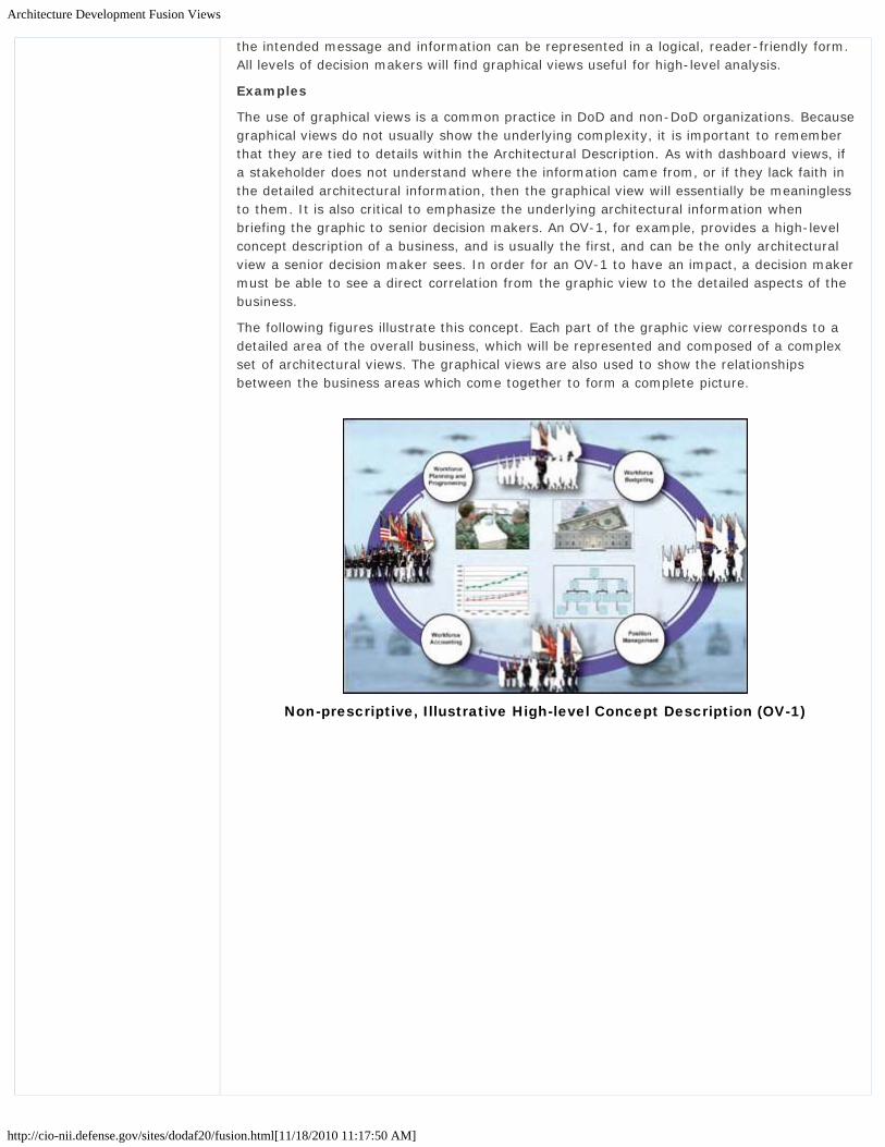
Architecture Development Fusion Views
http://cio-nii.defense.gov/sites/dodaf20/fusion.html[11/18/2010 11:17:50 AM]
the intended message and information can be represented in a logical, reader-friendly form.All levels of decision makers will find graphical views useful for high-level analysis.
Examples
The use of graphical views is a common practice in DoD and non-DoD organizations. Becausegraphical views do not usually show the underlying complexity, it is important to rememberthat they are tied to details within the Architectural Description. As with dashboard views, ifa stakeholder does not understand where the information came from, or if they lack faith inthe detailed architectural information, then the graphical view will essentially be meaninglessto them. It is also critical to emphasize the underlying architectural information whenbriefing the graphic to senior decision makers. An OV-1, for example, provides a high-levelconcept description of a business, and is usually the first, and can be the only architecturalview a senior decision maker sees. In order for an OV-1 to have an impact, a decision makermust be able to see a direct correlation from the graphic view to the detailed aspects of thebusiness.
The following figures illustrate this concept. Each part of the graphic view corresponds to adetailed area of the overall business, which will be represented and composed of a complexset of architectural views. The graphical views are also used to show the relationshipsbetween the business areas which come together to form a complete picture.
Non-prescriptive, Illustrative High-level Concept Description (OV-1)

Architecture Development Fusion Views
http://cio-nii.defense.gov/sites/dodaf20/fusion.html[11/18/2010 11:17:50 AM]
Non-prescriptive, Illustrative High-level Operational ConnectivityDescription (OV-2)
Graphical views enable the efficient communication of complex quantitative ideas. In asociety that is fascinated with visual stimulation, the use of graphical views provides anattractive and efficient communications tool. When effectively designed, graphical views canfacilitate understanding and recognition; promote analysis; and support learning and sharingof ideas.
Go to top of page ?
Privacy Policy | Web Policy | Contact | Submit Change Requests

Architecture Development Reference Models
http://cio-nii.defense.gov/sites/dodaf20/reference.html[11/18/2010 11:18:11 AM]
Home DoDAF-DM2 WG DoDAF Journal DoD Meta Data Registry IDEAS Links
Architecture Development
Reference Models
Reference models provide textual extractions of underlying architectural data. As the notionalreference model figure below illustrates, reference models capture the elements of thearchitectural views, and translate those elements into text. This reference model provides aframework for describing important elements of the FEA in a common and consistent way.The FEA consists of five reference models: Performance Reference Model (PRM), BusinessReference Model (BRM), Service Component Reference Model (SRM), Data Reference Model(DRM), and the Technical Reference Model (TRM). Through the use of this commonframework and vocabulary, IT portfolios can be better managed and leveraged across theFederal Government.
A Notional Reference Model
Purpose and Audience
Reference models are designed to facilitate cross-agency analysis, through the developmentof a common taxonomy and ontology for describing the business operations of Federalagencies, independent of any specific agency. Cross-agency analysis is used by planners andprocess owners to identify duplicate investments, gaps, and opportunities for collaborationwithin and across agencies. Collectively, the reference models comprise a framework fordescribing important elements of the FEA in a common and consistent way. Through the useof this common framework and vocabulary, IT portfolios can be better managed and
Introduction
What is New in DoDAF V2.0
Vision for DoDAF V2.0
Architecture Resources
DoDAF V1.5 Support
Relationships to otherFrameworks
Background
Architecture Development
6-Step ArchitectureDevelopment Process
What Does the Decision-Maker Do?
What Does the Architect Do?
Enterprise Architecture
Scoping Architectures
Planning
Analytics
Presentation
Overview
Choosing an AppropriatePresentation Technique
Composite Views
Dashboard Views
Fusion Views
Graphics View
Reference Models
Security
Viewpoints
Models
DM2
Manager Role
Department of Defense

Architecture Development Reference Models
http://cio-nii.defense.gov/sites/dodaf20/reference.html[11/18/2010 11:18:11 AM]
leveraged across the Federal Government.
Examples
One example of a reference model is the FEA BRM. The BRM provides an organized,hierarchical construct for describing the day-to-day business operations of the FederalGovernment. While many models exist for describing organizations, (organization charts,location maps, etc.) this model presents the business using a functionally driven approach.The Lines of Business and Sub-functions that comprise the BRM represent a departure fromprevious models of the Federal Government that use antiquated, stove-piped, agency-oriented frameworks. The BRM is the first layer of the Federal Enterprise Architecture, and itis the main viewpoint for the analysis of data, service components, and technology:
BRM Structure
The BRM is broken into four areas: Services for Citizens, Mode of Delivery, Support Deliveryof Services, and Management of Government Resources. The model's four Business Areasare decomposed into 39 Lines of Business. Each business line includes a collection of Sub-functions that represent the lowest level of granularity in the BRM. For example, theEnvironmental Management Line of Business encompasses three Sub-functions: (1)Environmental Monitoring and Forecasting; (2) Environmental Remediation; and (3) PollutionPrevention and Control. Within each Sub-function are the agency-specific business functions,processes, and activities:
BRM Areas
Architect Role
Developer Role
Site Map

Architecture Development Reference Models
http://cio-nii.defense.gov/sites/dodaf20/reference.html[11/18/2010 11:18:11 AM]
Go to top of page ?
Privacy Policy | Web Policy | Contact | Submit Change Requests

Architecture Development - Security
http://cio-nii.defense.gov/sites/dodaf20/security.html[11/18/2010 11:18:39 AM]
Home DoDAF-DM2 WG DoDAF Journal DoD Meta Data Registry IDEAS Links
Architecture Development
Security
Addressing Security Issues in DoDAF-Conformant Architecture Development
Security continues to be a critical concern within the DoD, and Architectural Descriptiondevelopment efforts at any level need to ensure that appropriate security concerns areaddressed clearly, so that any decisions made that rely on the Architectural Descriptions arevalid and useful. Security concerns are routinely addressed through the risk assessmentprocess.
Each of the individual models provides the architect and development team with a set ofdata for collecting, documenting, and maintaining security data. These data support physical,procedural, communications security (COMSEC), Transient Electromagnetic Pulse EmanationStandard (TEMPEST), and Information Security (INFOSEC) concerns. DM2 incorporates theIntelligence Community Information Security Marking (IC ISM) standard for classificationmarkings of architecture information.
How Does DoDAF Represent Security?
Capabilities are subject to a variety of threats to the integrity, availability, and confidentialityof their operation. These threats range from failures of equipment, attempts to gainunauthorized access to their services and data, to sabotage of their functions. Securityengineering is concerned with identifying the potential threats to a capability, and then,using a risk management approach, devising a set of measures which reduce the known andpotential vulnerabilities to an acceptable level. In general, the measures that can be appliedfall into the following categories:
Physical – measures such as guards, guard dogs, fences, locks, sensors, includingClosed Circuit Television, strong rooms, armor, weapons systems, etc.Procedural – the specification of procedures, including vetting (which tests thatpersonnel have a sufficient level of integrity and trust to be given responsibility toaccess and use a capability’s services and data) that will reduce the likelihood ofvulnerabilities being exploited.Communication Security (COMSEC) – using encryption and other techniques to ensurethat data transmission is available at sufficient bandwidth, that the traffic pattern andcontent of data in transit are indecipherable to a third party who might intercept thedata, and that its integrity is protected.Transient Electromagnetic Pulse Emanation Standard (TEMPEST) – measures toensure that the electromagnetic transmissions from equipment can’t be intercepted toderive information about the equipment’s operation and the data it processes.Information Security (INFOSEC) – ensuring the integrity, availability andconfidentiality of data and IT-based services.
In general, the measures employed to protect a capability will have undesirable impacts onall of the capability’s lines of development, and in particular on it’s deploy ability, usabilityand procurement and maintenance costs. It is therefore desirable to minimize the strengthof the measures to be employed in a fashion commensurate with the value of the assetsbeing protected. This requires a risk-managed approach based on the assessment of thelikely threats posed to the asset. A risk assessment approach considers the followingcharacteristics:
Introduction
What is New in DoDAF V2.0
Vision for DoDAF V2.0
Architecture Resources
DoDAF V1.5 Support
Relationships to otherFrameworks
Background
Architecture Development
6-Step ArchitectureDevelopment Process
What Does the Decision-Maker Do?
What Does the Architect Do?
Enterprise Architecture
Scoping Architectures
Planning
Analytics
Presentation
Security
Viewpoints
Models
DM2
Manager Role
Architect Role
Developer Role
Department of Defense

Architecture Development - Security
http://cio-nii.defense.gov/sites/dodaf20/security.html[11/18/2010 11:18:39 AM]
Environment – The level of hostility of the environment the asset is being deployed to.Asset Value – this is denoted by a protective marking which indicates the impact ofthe loss or disclosure of the asset would have on the effective operation of thegovernment and its departments of state.Criticality – an assessment of the criticality of the asset to enabling the government toundertake its activities.Personnel Clearance – a measure of the degree of trust that the government is willingto put in the personnel that will have (direct or indirect) access to the asset.
The aim of this guidance for representing security considerations is to enable sufficientinformation to be recorded for interested parties (accreditors, security advisors, users,system managers) to understand the potential security exposure of capabilities so thatsecurity can be managed effectively throughout the life of a capability.
The table below shows the DoDAF scheme for assigning security characteristics andprotective measures to elements of DoDAF. There is not a specific security viewpoint inDoDAF; security information can be shown on models using annotations and call–outs. TheDoDAF Meta-Model contains the concepts, associations, and attributes for capturing andrepresenting security characteristics in a consistent way between models.
DoDAF Viewpoints and Concept Mapped to Security Characteristicsand Protective Measures
Viewpoint ConceptSecurity
CharacteristicsProtectiveMeasures
Notes
Capability Capabilityrequirement
SecurityMarkingCriticalityEnvironmentUser SecurityProfile
The security characteristics ofcapability requirements provide thesecurity envelope for the capabilityfor a particular timeframe.
Operational Location User SecurityProfileEnvironment
The User Security Profile is thelowest clearance of the users withina location, facility, or organization.The environment identifies the mosthostile conditions for the location,facility, or organization.
Activity SecurityMarkingCriticality
The security marking identifies thehighest security marking ofinformation that will be processedby a Operational Activity and theCriticality measures the impact ongovernment operations with thedisruption of the operationalactivity.
Site Map
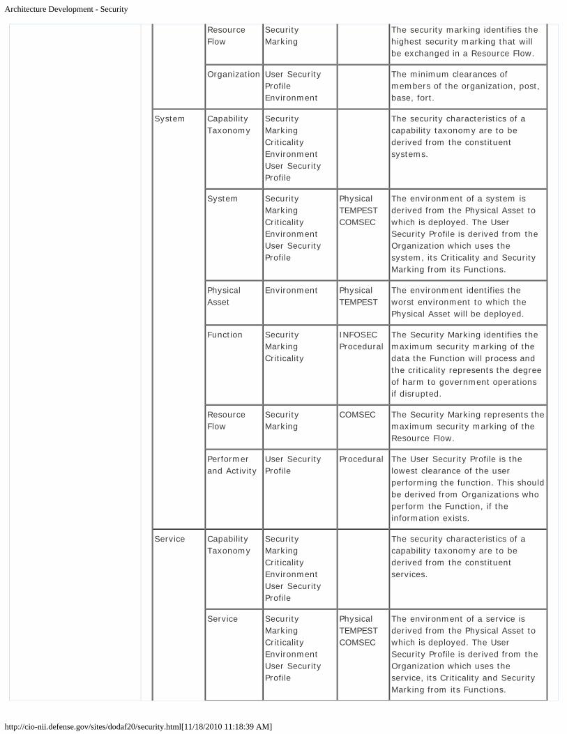
Architecture Development - Security
http://cio-nii.defense.gov/sites/dodaf20/security.html[11/18/2010 11:18:39 AM]
ResourceFlow
SecurityMarking
The security marking identifies thehighest security marking that willbe exchanged in a Resource Flow.
Organization User SecurityProfileEnvironment
The minimum clearances ofmembers of the organization, post,base, fort.
System CapabilityTaxonomy
SecurityMarkingCriticalityEnvironmentUser SecurityProfile
The security characteristics of acapability taxonomy are to bederived from the constituentsystems.
System SecurityMarkingCriticalityEnvironmentUser SecurityProfile
PhysicalTEMPESTCOMSEC
The environment of a system isderived from the Physical Asset towhich is deployed. The UserSecurity Profile is derived from theOrganization which uses thesystem, its Criticality and SecurityMarking from its Functions.
PhysicalAsset
Environment PhysicalTEMPEST
The environment identifies theworst environment to which thePhysical Asset will be deployed.
Function SecurityMarkingCriticality
INFOSECProcedural
The Security Marking identifies themaximum security marking of thedata the Function will process andthe criticality represents the degreeof harm to government operationsif disrupted.
ResourceFlow
SecurityMarking
COMSEC The Security Marking represents themaximum security marking of theResource Flow.
Performerand Activity
User SecurityProfile
Procedural The User Security Profile is thelowest clearance of the userperforming the function. This shouldbe derived from Organizations whoperform the Function, if theinformation exists.
Service CapabilityTaxonomy
SecurityMarkingCriticalityEnvironmentUser SecurityProfile
The security characteristics of acapability taxonomy are to bederived from the constituentservices.
Service SecurityMarkingCriticalityEnvironmentUser SecurityProfile
PhysicalTEMPESTCOMSEC
The environment of a service isderived from the Physical Asset towhich is deployed. The UserSecurity Profile is derived from theOrganization which uses theservice, its Criticality and SecurityMarking from its Functions.

Architecture Development - Security
http://cio-nii.defense.gov/sites/dodaf20/security.html[11/18/2010 11:18:39 AM]
PhysicalAsset
Environment PhysicalTEMPEST
The environment identifies theworst environment to which thePhysical Asset will be deployed.
Activity SecurityMarkingCriticality
INFOSECProcedural
The Security Marking identifies themaximum security marking of thedata the Function will process andthe criticality represents the degreeof harm to government operationsif disrupted.
ResourceFlow
SecurityMarking
COMSEC The Security Marking represents themaximum security marking of theResource Flow.
Performerand Activity
User SecurityProfile
Procedural The User Security Profile is thelowest clearance of the userperforming the function. This shouldbe derived from Organizations whoperform the Function, if theinformation exists.
Standards Performer SecurityMarking
INFOSECProcedural
The Security Marking identifies thesecurity standard for the data theFunction will process and thecriticality represents the degree ofharm to government operations ifthere is unauthorized access.
Go to top of page ?
Privacy Policy | Web Policy | Contact | Submit Change Requests
DoDAF Viewpoints and Models
http://cio-nii.defense.gov/sites/dodaf20/viewpoints.html[11/18/2010 11:42:04 AM]
Home DoDAF-DM2 WG DoDAF Journal DoD Meta Data Registry IDEAS Links
DoDAF Viewpoints and ModelsDoDAF has been designed to meet the specific business and operational needs of the DoD. Itdefines a way of representing an enterprise architecture that enables stakeholders to focuson specific areas of interests in the enterprise, while retaining sight of the big picture. Toassist decision-makers, DoDAF provides the means of abstracting essential information fromthe underlying complexity and presenting it in a way that maintains coherence andconsistency. One of the principal objectives is to present this information in a way that isunderstandable to the many stakeholder communities involved in developing, delivering, andsustaining capabilities in support of the stakeholder's mission. It does so by dividing theproblem space into manageable pieces, according to the stakeholder's viewpoint, furtherdefined as DoDAF-described Models.
Each viewpoint has a particular purpose, and usually presents one or combinations of thefollowing:
Broad summary information about the whole enterprise (e.g., high-level operationalconcepts).Narrowly focused information for a specialist purpose (e.g., system interfacedefinitions).Information about how aspects of the enterprise are connected (e.g., how business oroperational activities are supported by a system, or how program management bringstogether the different aspects of network enabled capability).
However, it should be emphasized that DoDAF is fundamentally about creating a coherentmodel of the enterprise to enable effective decision-making. The presentational aspectsshould not overemphasize the pictorial presentation at the expense of the underlying data.
DoDAF organizes the DoDAF-described Models into the following viewpoints:
The All Viewpoint describes the overarching aspects of architecture context that relateto all viewpoints.The Capability Viewpoint articulates the capability requirements, the delivery timing,and the deployed capability.The Data and Information Viewpoint articulates the data relationships and alignmentstructures in the architecture content for the capability and operational requirements,system engineering processes, and systems and services.The Operational Viewpoint includes the operational scenarios, activities, andrequirements that support capabilities.The Project Viewpoint describes the relationships between operational and capabilityrequirements and the various projects being implemented. The Project Viewpoint alsodetails dependencies among capability and operational requirements, systemengineering processes, systems design, and services design within the DefenseAcquisition System process. An example is the Vcharts in Chapter 4 of the DefenseAcquisition Guide.The Services Viewpoint is the design for solutions articulating the Performers,Activities, Services, and their Exchanges, providing for or supporting operational andcapability functions.The Standards Viewpoint articulates the applicable operational, business, technical,and industry policies, standards, guidance, constraints, and forecasts that apply tocapability and operational requirements, system engineering processes, and systems
Introduction
What is New in DoDAF V2.0
Vision for DoDAF V2.0
Architecture Resources
DoDAF V1.5 Support
Relationships to otherFrameworks
Background
Architecture Development
Viewpoints
All Viewpoint
Capability Viewpoint
Data and InformationViewpoint
Operational Viewpoint
Project Viewpoint
Services Viewpoint
Standards Viewpoint
Systems Viewpoint
Models
DM2
Manager Role
Architect Role
Developer Role
Department of Defense

DoDAF Viewpoints and Models
http://cio-nii.defense.gov/sites/dodaf20/viewpoints.html[11/18/2010 11:42:04 AM]
and services.The Systems Viewpoint, for Legacy support, is the design for solutions articulating thesystems, their composition, interconnectivity, and context providing for or supportingoperational and capability functions.
A presentation of these viewpoints is portrayed in graphic format below:
DoDAF Viewpoints
DoDAF V2.0 is a more focused approach to supporting decision-makers than prior versions.In the past, decision-makers would look at DoDAF offerings and decide which wereappropriate to their decision process. An example is the JCIDS process architecturerequirements inside the JCIDS documentation (ICD, CDD, CPD, etc.). Additionally, olderversion Architectural Description products were hard-coded in regard to content and howthey were visualized. Many times, these design products were not understandable or usefulto their intended audience. DoDAF V2.0, based on process owner input, has increased focuson architectural data, and a new approach for presenting architecture information hasaddressed the issues. The viewpoints categorize the models as follows:
As illustrated below, the original viewpoints (Operational Viewpoint, Systems andServices Viewpoint, Technical Standards Viewpoint, and the All Viewpoint) have hadtheir Models reorganized to better address their purposes. The Services portion of theolder Systems and Services Viewpoint is now a Services Viewpoint that addresses inmore detail our net-centric or services-oriented implementations.
Site Map

DoDAF Viewpoints and Models
http://cio-nii.defense.gov/sites/dodaf20/viewpoints.html[11/18/2010 11:42:04 AM]
DoDAF V1.5 Evolution to DoDAF V2.0
All the models of data (conceptual, logical, or physical) have been placed into the Dataand Information Viewpoint rather than spread throughout the Operational Viewpointand Systems and Services Viewpoints.The Systems Viewpoint accommodates the legacy system descriptions.The new Standards Viewpoint can now describe business, commercial, and doctrinalstandards, as well as the technical standards applicable to our solutions, which mayinclude systems and services.The Operational Viewpoint now can describe rules and constraints for any function(business, intelligence, warfighting, etc.) rather that just those derived from datarelationships.Due to the emphasis within the Department on Capability Portfolio Management andfeedback from the Acquisition community, the Capability Viewpoint and ProjectViewpoint have been added through a best-of-breed analysis of the MODAF and NAFconstructs.
Workshops have brought the Systems Engineering community and the architecturecommunity closer together in defining the DoDAF architecture content that would be usefulto the Systems Engineering process, and this has resulted in an understanding which theentire set of viewpoints and the underlying architectural data can be used in the SystemEngineering processes. There is not a set of separate System Engineering viewpoint orDoDAF-described Models as the system engineer and system engineering decision-makerscan use the existing DoDAF-described Models and their own defined Fit-for-Purpose Views.
The approach to the presentation of Architectural Description moves away from static andrigid one-size-fits-all templates of architecture portrayals for architects. The term we havecoined is "Fit-for-Purpose" presentation. Through various techniques and applications, thepresentation of Architectural data increases customer understanding and architecture'susefulness to decision-making by putting the data underlying the architectural models intothe context of the problem space for each decision-maker.
Viewpoint and DoDAF-described Model Descriptions
The following DoDAF Viewpoints and DoDAF-described Models are discussed below with

DoDAF Viewpoints and Models
http://cio-nii.defense.gov/sites/dodaf20/viewpoints.html[11/18/2010 11:42:04 AM]
some details, such as model uses and model descriptions:
All ViewpointCapability ViewpointData and Information ViewpointOperational ViewpointProject ViewpointServices ViewpointStandards ViewpointSystems Viewpoint
For the DoDAF-described Model descriptions, a major source of material was adapted fromMODAF. In addition, a note on system engineering is included.
The Views described in DoDAF, including those that are legacy Views from previousversions of the Framework, are provided as pre-defined examples that can be used whendeveloping presentations of architectural data.
DoDAF is prescribed for the use and development of Architectural Descriptions in theDepartment. Specific DoDAF-described Models for a particular purpose are prescribed byprocess-owners. All the DoDAF-described Models do not have to be created. DoDAF V2.0is "Fit-for-Purpose", based on the decision-maker needs. DoDAF does not prescribe anyparticular Views, but instead concentrates on data as the necessary ingredient forarchitecture development. However, other regulations and instructions from both DoDand CJCS may have particular presentation view requirements. These Views aresupported by DoDAF 2.0, and should be consulted for specific view requirements.
Go to top of page ?
Privacy Policy | Web Policy | Contact | Submit Change Requests

DoDAF Viewpoints and Models - All Viewpoint
http://cio-nii.defense.gov/sites/dodaf20/all_view.html[11/18/2010 11:42:30 AM]
Home DoDAF-DM2 WG DoDAF Journal DoD Meta Data Registry IDEAS Links
DoDAF Viewpoints and Models
All Viewpoint
There are some overarching aspects of an Architectural Description that are captured in theAV DoDAF-described Models. The AV DoDAF-described Models provide information pertinentto the entire Architectural Description rather than representing a distinct viewpoint. AVDoDAF-described Models provide an overview of the architecturectural effort including suchthings as the scope, context, rules, constraints, assumptions, and the derived vocabularythat pertains to the Architectural Description. It captures the intent of the ArchitecturalDescription to help ensure its continuity in the face of leadership, organizational, and otherchanges that can occur over a long development effort.
All Viewpoint Model Descriptions
Models Descriptions
AV-1 Overview and SummaryInformation
Describes a Project's Visions, Goals, Objectives,Plans, Activities, Events, Conditions, Measures,Effects (Outcomes), and produced objects.
AV-2 Integrated Dictionary An architectural data repository with definitionsof all terms used throughout the architecturaldata and presentations.
Uses of All Viewpoint DoDAF-described Models. The AV DoDAF-described Modelscaptures the scope of the architecture and where the architecture fits in relationship to otherarchitectures. Another use of the All Viewpoint is for the registration of the architecture tosupport the net-centric goals of making Architectural Descriptions visible (Discoverable).
Mappings of the All Viewpoint DoDAF-described Models to the DM2 Concepts, Associations,and Attributes are in DM2 Concepts, Associations, and Attributes Mapping to DoDAF-described Models. The DM2 Concepts, Associations, and Attributes are described in theDoDAF Meta-model Data Dictionary.
Go to top of page ?
Introduction
What is New in DoDAF V2.0
Vision for DoDAF V2.0
Architecture Resources
DoDAF V1.5 Support
Relationships to otherFrameworks
Background
Architecture Development
Viewpoints
All Viewpoint
Capability Viewpoint
Data and InformationViewpoint
Operational Viewpoint
Project Viewpoint
Services Viewpoint
Standards Viewpoint
Systems Viewpoint
Models
DM2
Manager Role
Architect Role
Developer Role
Department of Defense

DoDAF Viewpoints and Models - All Viewpoint
http://cio-nii.defense.gov/sites/dodaf20/all_view.html[11/18/2010 11:42:30 AM]
Site Map
Privacy Policy | Web Policy | Contact | Submit Change Requests

All Viewpoints - Overview
http://cio-nii.defense.gov/sites/dodaf20/AV-1.html[11/18/2010 11:42:44 AM]
Home DoDAF-DM2 WG DoDAF Journal DoD Meta Data Registry IDEAS Links
DoDAF Viewpoints and Models
All Viewpoint
AV-1 Overview and Summary Information. The overview and summary informationcontained within the AV-1 provides executive-level summary information in a consistentform that allows quick reference and comparison between Architectural Descriptions. Thewritten content of the AV-1 content describes the concepts contained in the pictorialrepresentation of the OV-1.
The AV-1 frames the context for the Architectural Description. The AV-1 includesassumptions, constraints, and limitations that may affect high-level decisions relating to anarchitecture-based work program. It should contain sufficient information to enable a readerto select a single Architectural Description from among many to read in more detail. The AV-1 serves two additional purposes:
In the initial phases of architecture development, it serves as a planning guide.When the architecture is built, the AV-1 provides summary information concerningwho, what, when, why, and how of the plan as well as a navigation aid to the modelsthat have been created.
The usage of the AV-1 is to:
Scope the architecture effort.Provide context to the architecture effort.Define the architecture effort.Summarize the findings from the architecture effort.Assist search within an architecture repository.
Detailed Description:
An enterprise has an architecture, which is manifested through an Architectural Description(in this case, a DoDAF described Architectural Description). That Architectural Descriptionconsists of a number of populated views each of which is an instance of a specific model or acombination of model. DoDAF consists of a set of viewpoints and these are organized interms of models. Each model is associated with a specific set of concerns that certainstakeholders have, and which the models constructed are intended to address. Thestakeholder groupings tend to align with the model definitions within a viewpoint (so theDoDAF Operational Viewpoint relates to operational stakeholders, i.e., end users). Finallyeach Architectural Description has a rationale that governs the selection of Models that willbe used and the scope of the underlying models. The AV-1 is intended to describe this.
The AV-1 is usually a structured text product. An architecting organization may create atemplate for the AV-1 that can then be used to create a consistent set of information acrossdifferent architecture-based projects. While the AV-1 is often dispensed with or "retrofitted"to a finished architecture package, it's desirable to do it up-front because the AV-1 providesa summary of a given Architectural Description and it documents the following descriptions:
Architectural Description Identification - Identifies the Architectural Description effortname, the architect, and the organization developing the Architectural Description. Italso includes assumptions and constraints, identifies the approving authority and thecompletion date, and records the level of effort required to develop the Architectural
Introduction
What is New in DoDAF V2.0
Vision for DoDAF V2.0
Architecture Resources
DoDAF V1.5 Support
Relationships to otherFrameworks
Background
Architecture Development
Viewpoints
All Viewpoint
Capability Viewpoint
Data and InformationViewpoint
Operational Viewpoint
Project Viewpoint
Services Viewpoint
Standards Viewpoint
Systems Viewpoint
Models
DM2
Manager Role
Architect Role
Developer Role
Department of Defense
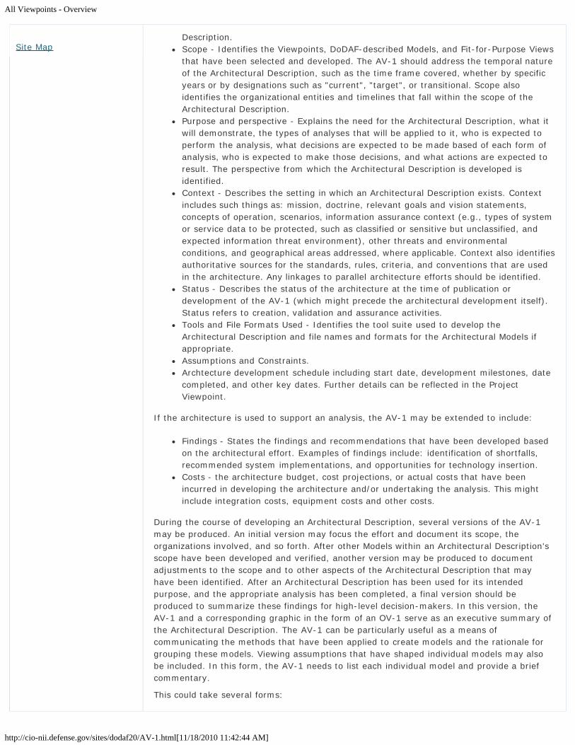
All Viewpoints - Overview
http://cio-nii.defense.gov/sites/dodaf20/AV-1.html[11/18/2010 11:42:44 AM]
Description.Scope - Identifies the Viewpoints, DoDAF-described Models, and Fit-for-Purpose Viewsthat have been selected and developed. The AV-1 should address the temporal natureof the Architectural Description, such as the time frame covered, whether by specificyears or by designations such as "current", "target", or transitional. Scope alsoidentifies the organizational entities and timelines that fall within the scope of theArchitectural Description.Purpose and perspective - Explains the need for the Architectural Description, what itwill demonstrate, the types of analyses that will be applied to it, who is expected toperform the analysis, what decisions are expected to be made based of each form ofanalysis, who is expected to make those decisions, and what actions are expected toresult. The perspective from which the Architectural Description is developed isidentified.Context - Describes the setting in which an Architectural Description exists. Contextincludes such things as: mission, doctrine, relevant goals and vision statements,concepts of operation, scenarios, information assurance context (e.g., types of systemor service data to be protected, such as classified or sensitive but unclassified, andexpected information threat environment), other threats and environmentalconditions, and geographical areas addressed, where applicable. Context also identifiesauthoritative sources for the standards, rules, criteria, and conventions that are usedin the architecture. Any linkages to parallel architecture efforts should be identified.Status - Describes the status of the architecture at the time of publication ordevelopment of the AV-1 (which might precede the architectural development itself).Status refers to creation, validation and assurance activities.Tools and File Formats Used - Identifies the tool suite used to develop theArchitectural Description and file names and formats for the Architectural Models ifappropriate.Assumptions and Constraints.Archtecture development schedule including start date, development milestones, datecompleted, and other key dates. Further details can be reflected in the ProjectViewpoint.
If the architecture is used to support an analysis, the AV-1 may be extended to include:
Findings - States the findings and recommendations that have been developed basedon the architectural effort. Examples of findings include: identification of shortfalls,recommended system implementations, and opportunities for technology insertion.Costs - the architecture budget, cost projections, or actual costs that have beenincurred in developing the architecture and/or undertaking the analysis. This mightinclude integration costs, equipment costs and other costs.
During the course of developing an Architectural Description, several versions of the AV-1may be produced. An initial version may focus the effort and document its scope, theorganizations involved, and so forth. After other Models within an Architectural Description'sscope have been developed and verified, another version may be produced to documentadjustments to the scope and to other aspects of the Architectural Description that mayhave been identified. After an Architectural Description has been used for its intendedpurpose, and the appropriate analysis has been completed, a final version should beproduced to summarize these findings for high-level decision-makers. In this version, theAV-1 and a corresponding graphic in the form of an OV-1 serve as an executive summary ofthe Architectural Description. The AV-1 can be particularly useful as a means ofcommunicating the methods that have been applied to create models and the rationale forgrouping these models. Viewing assumptions that have shaped individual models may alsobe included. In this form, the AV-1 needs to list each individual model and provide a briefcommentary.
This could take several forms:
Site Map

All Viewpoints - Overview
http://cio-nii.defense.gov/sites/dodaf20/AV-1.html[11/18/2010 11:42:44 AM]
It could refer to one or more DoDAF-described Models.It could refer to the DoDAF Community of Practice.It could refer to a focus for the work, e.g., integration or security.It could refer to a combination of these.
Finally, each Architectural Description has a rationale that governs the selection of theModels used and the scope of the underlying models as a result of employing the 6-StepArchitecture Development Process. The AV-1 DoDAF-described Model is intended to describethe decisions made throughout that process.
AV-2: Integrated Dictionary >>
Go to top of page ?
Privacy Policy | Web Policy | Contact | Submit Change Requests

All Viewpoints - Integrated Dictionary
http://cio-nii.defense.gov/sites/dodaf20/AV-2.html[11/18/2010 11:43:01 AM]
Home DoDAF-DM2 WG DoDAF Journal DoD Meta Data Registry IDEAS Links
DoDAF Viewpoints and Models
All Viewpoint
AV-2: Integrated Dictionary. The AV-2 presents all the metadata used in an architecture.An AV-2 presents all the data as a hierarchy, provides a text definition for each one andreferences the source of the element (e.g., DoDAF Meta-model, IDEAS, a publisheddocument or policy).
An AV-2 shows elements from the DoDAF Meta-model that have been described in theArchitectural Description and new elements (i.e., not in the DM2) that have been introducedby the Architectural Description.
It is essential that organizations within the DoD use the same terms to refer to a thing.Because of the interrelationship among models and across architecture efforts, it is useful todefine common terminology with common definitions (referred to as taxonomies) in thedevelopment of the models within the Architectural Description. These taxonomies can beused as building blocks for DoDAF-described Models and Fit-for-Purpose Views within theArchitectural Description. The need for standard taxonomies derives from lessons learnedfrom early DoD Architectural Description development issues as well as from federation pilotsconducted within the Department. Federation of Architectural Descriptions were made muchmore difficult because of the use of different terminology to represent the same architecturaldata. Use of taxonomies to build models for the architecture has the following benefits overfree-text labeling:
Provides consistency across populated views, based on DoDAF-described Models.Provides consistency across Architectural Descriptions.Facilitates Architectural Description development, validation, maintenance, and re-use.Traces architectural data to authoritative data sources.
This is facilitated by the DM2. Architectural Descriptions can often introduce new terms -possibly because the architecture is covering new technology or business activities. Thepurpose of the AV-2 is to provide a means to explain the terms and abbreviations used inbuilding the architecture and, as necessary, submit them for review and inclusion intoauthoritative vocabularies developed by COIs that are pertinent to the ArchitecturalDescription content.
In the creation of any Architectural Description, reuse of authoritative external taxonomycontent, e.g., the FEA Reference Models, or the Joint Common System Function List, or anylisted in Architecture Resources, are important to aligning the architectural content acrossmany descriptions to increase their understandability, interoperability, ArchitectureFederation, and compliance. A discussion on the use of taxonomies in the development ofthe AV-2 and the architecture effort is below.
Detailed Description:
The AV-2 content can be organized by the following areas within the DM2 that can be usedto expedite architecture development:
Capabilities: The taxonomy should minimally consist of names, descriptions, andconditions that may be applicable to performance measures.Resource Flow. The taxonomy should minimally consist of names of information
Introduction
What is New in DoDAF V2.0
Vision for DoDAF V2.0
Architecture Resources
DoDAF V1.5 Support
Relationships to otherFrameworks
Background
Architecture Development
Viewpoints
All Viewpoint
Capability Viewpoint
Data and InformationViewpoint
Operational Viewpoint
Project Viewpoint
Services Viewpoint
Standards Viewpoint
Systems Viewpoint
Models
DM2
Manager Role
Architect Role
Developer Role
Department of Defense
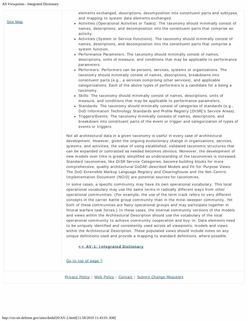
All Viewpoints - Integrated Dictionary
http://cio-nii.defense.gov/sites/dodaf20/AV-2.html[11/18/2010 11:43:01 AM]
elements exchanged, descriptions, decomposition into constituent parts and subtypes,and mapping to system data elements exchanged.Activities (Operational Activities or Tasks). The taxonomy should minimally consist ofnames, descriptions, and decomposition into the constituent parts that comprise anactivity.Activities (System or Service Functions). The taxonomy should minimally consist ofnames, descriptions, and decomposition into the constituent parts that comprise asystem function.Performance Parameters. The taxonomy should minimally consist of names,descriptions, units of measure, and conditions that may be applicable to performanceparameters.Performers: Performers can be persons, services, systems or organizations. Thetaxonomy should minimally consist of names, descriptions, breakdowns intoconstituent parts (e.g., a services comprising other services), and applicablecategorizations. Each of the above types of performers is a candidate for a being ataxonomy.Skills: The taxonomy should minimally consist of names, descriptions, units ofmeasure, and conditions that may be applicable to performance parameters.Standards: The taxonomy should minimally consist of categories of standards (e.g.,DoD Information Technology Standards and Profile Registry [DISR]'s Service Areas).Triggers/Events: The taxonomy minimally consists of names, descriptions, andbreakdown into constituent parts of the event or trigger and categorization of types ofevents or triggers.
Not all architectural data in a given taxonomy is useful in every case of architecturaldevelopment. However, given the ongoing evolutionary change in organizations, services,systems, and activities, the value of using established, validated taxonomic structures thatcan be expanded or contracted as needed becomes obvious. Moreover, the development ofnew models over time is greatly simplified as understanding of the taxonomies is increased.Standard taxonomies, like DISR Service Categories, become building blocks for morecomprehensive, quality architectural DoDAF-described Models and Fit-for-Purpose Views.The DoD Extensible Markup Language Registry and Clearinghouse and the Net-CentricImplementation Document (NCID) are potential sources for taxonomies.
In some cases, a specific community may have its own operational vocabulary. This localoperational vocabulary may use the same terms in radically different ways from otheroperational communities. (For example, the use of the term track refers to very differentconcepts in the carrier battle group community than in the mine-sweeper community. Yetboth of these communities are Navy operational groups and may participate together inlittoral warfare task forces.) In these cases, the internal community versions of the modelsand views within the Architectural Description should use the vocabulary of the localoperational community to achieve community cooperation and buy-in. Data elements needto be uniquely identified and consistently used across all viewpoints, models and viewswithin the Architectural Description. These populated views should include notes on anyunique definitions used and provide a mapping to standard definitions, where possible.
<< AV-1: Integrated Dictionary
Go to top of page ?
Site Map
Privacy Policy | Web Policy | Contact | Submit Change Requests

DoDAF Viewpoints and Models - Capability Viewpoint
http://cio-nii.defense.gov/sites/dodaf20/capability.html[11/18/2010 11:43:19 AM]
Home DoDAF-DM2 WG DoDAF Journal DoD Meta Data Registry IDEAS Links
DoDAF Viewpoints and Models
Capability Viewpoint
The Capability Viewpoint and the DoDAF-described Models within the viewpoint areintroduced into DoDAF V2.0 to address the concerns of Capability Portfolio Managers. Inparticular, the Capability Models describe capability taxonomy and capability evolution.
The DoD increasingly employs incremental acquisition to help manage the risks of complexprocurements. Consequently, there is a need to provide visualizations of the evolvingcapabilities so that Portfolio Managers can synchronize the introduction of capabilityincrements across a portfolio of projects. The Capability Models included within DoDAF arebased on the program and capability information used by Portfolio Managers to capture theincreasingly complex relationships between interdependent projects and capabilities.
Another justification for the Capability Viewpoint is the increasing importance oftransformational programs within the DoD (e.g., Global Exchange [GEX], Defense AcquisitionInitiative [DAI]). These types of programs are focused on the delivery of capabilities and donot conform to the standard for project management and tend to be benefit-driven ratherthan capability delivery focused. An ability to view these transformational programs, andtheir interdependencies, provides a potentially powerful tool for DoD Enterprise Architects.
Capability Model Descriptions
Model Description
CV-1: Vision Describes a Project's Visions, Goals, Objectives, Plans,Activities, Events, Conditions, Measures, Effects(Outcomes), and produced objects.
CV-2: Capability Taxonomy An architectural data repository with definitions of allterms used throughout the architectural data andpresentations.
CV-3: Capability Phasing The planned achievement of capability at differentpoints in time or during specific periods of time. TheCV-3 shows the capability phasing in terms of theactivities, conditions, desired effects, rules compliedwith, resource consumption and production, andmeasures, without regard to the performer andlocation solutions
CV-4: Capability Dependencies The dependencies between planned capabilities andthe definition of logical groupings of capabilities.
CV-5: Capability toOrganizational DevelopmentMapping
The fulfillment of capability requirements shows theplanned capability deployment and interconnection fora particular Capability Phase. The CV-5 shows theplanned solution for the phase in terms of performersand locations and their associated concepts.
CV-6: Capability to OperationalActivities Mapping
A mapping between the capabilities required and theoperational activities that those capabilities support.
CV-7: Capability to ServicesMapping
A mapping between the capabilities and the servicesthat these capabilities enable.
Introduction
What is New in DoDAF V2.0
Vision for DoDAF V2.0
Architecture Resources
DoDAF V1.5 Support
Relationships to otherFrameworks
Background
Architecture Development
Viewpoints
All Viewpoint
Capability Viewpoint
Data and InformationViewpoint
Operational Viewpoint
Project Viewpoint
Services Viewpoint
Standards Viewpoint
Systems Viewpoint
Models
DM2
Manager Role
Architect Role
Developer Role
Department of Defense

DoDAF Viewpoints and Models - Capability Viewpoint
http://cio-nii.defense.gov/sites/dodaf20/capability.html[11/18/2010 11:43:19 AM]
Mappings of the Capability Viewpoint DoDAF-described Models to the DM2 Concepts,Associations, and Attributes are in DM2 Concepts, Associations, and Attributes Mappingto DoDAF-described Models. The DM2 Concepts, Associations, and Attributes aredescribed in the DoDAF Meta-model Data Dictionary.
The Capability Viewpoint DoDAF-described Models are discussed with examples in the DoDAFProduct Development Questionnaire Analysis Report.
Use of Capability Viewpoint Models. The CV DoDAF-described Models are intended toprovide support to various decision processes within the Department, one of which isportfolio management. Since the DoD has moved toward the delivery of capabilities, thesemodels take on a more important role. Developing an architecture that includes therelationships necessary to enable a capability thread is essential to improving usability ofarchitectures, as well as increasing the value of federation.
In the above context, a capability thread is similar to the result of a query that would be runon a particular capability. For example, if an architecture were to include operationalactivities, rules, and systems, a capability thread would equate to the specific activities,rules, and systems that are linked to that particular capability. The CV DoDAF-describedModels are used to provide the strategic perspective and context for other architecturalinformation.
The concept of capability, as defined by its Meta-model Data Group allows one to answerquestions such as:
How does a particular capability or capabilities support the overall mission/vision?What outcomes are expected to be achieved by a particular capability or set ofcapabilities?What services are required to support a capability?What is the functional scope and organizational span of a capability or set ofcapabilities?What is our current set of capabilities that we are managing as part of a portfolio?
CV-1: Vision
CV-2: Capability Taxonomy
CV-3: Capability Phasing
CV-4: Capability Dependencies
CV-5: Capability to Organizational Development Mapping
CV-6: Capability to Operational Activities Mapping
CV-7: Capability to Services Mapping
Go to top of page ?
Site Map
Privacy Policy | Web Policy | Contact | Submit Change Requests

DoDAF - Viewpoints CV-1: Vision
http://cio-nii.defense.gov/sites/dodaf20/CV-1.html[11/18/2010 11:49:07 AM]
Home DoDAF-DM2 WG DoDAF Journal DoD Meta Data Registry IDEAS Links
DoDAF Viewpoints and Models
Capability Viewpoint - Capability Model Descriptions
CV-1: Vision
The CV-1 addresses the enterprise concerns associated with the overall vision fortransformational endeavors and thus defines the strategic context for a group of capabilities.The purpose of a CV-1 is to provide a strategic context for the capabilities described in theArchitectural Description. It also provides a high-level scope for the Architectural Descriptionwhich is more general than the scenario-based scope defined in an OV-1.
The intended usage is communication of the strategic vision regarding capabilitydevelopment.
Detailed Description:
The CV-1 defines the strategic context for a group of capabilities described in theArchitectural Description by outlining the vision for a capability area over a bounded periodof time. It describes how high-level goals and strategy are to be delivered in capabilityterms. A CV-1 may provide the blueprint for a transformational initiative. The CV-1 may beprimarily textual descriptions of the overarching objectives of the transformation or changeprogram that the Enterprise is engaged in. Of key importance is the identification of Goals,together with the desired outcomes and measurable benefits associated with these.
CV-1: Vision
CV-2: Capability Taxonomy
CV-3: Capability Phasing
CV-4: Capability Dependencies
CV-5: Capability to Organizational Development Mapping
CV-6: Capability to Operational Activities Mapping
CV-7: Capability to Services Mapping
Go to top of page ?
Introduction
What is New in DoDAF V2.0
Vision for DoDAF V2.0
Architecture Resources
DoDAF V1.5 Support
Relationships to otherFrameworks
Background
Architecture Development
Viewpoints
All Viewpoint
Capability Viewpoint
Data and InformationViewpoint
Operational Viewpoint
Project Viewpoint
Services Viewpoint
Standards Viewpoint
Systems Viewpoint
Models
DM2
Manager Role
Architect Role
Developer Role
Department of Defense

DoDAF - Viewpoints CV-1: Vision
http://cio-nii.defense.gov/sites/dodaf20/CV-1.html[11/18/2010 11:49:07 AM]
Site Map
Privacy Policy | Web Policy | Contact | Submit Change Requests

DoDAF - Viewpoints CV-2: Capability Taxonomy
http://cio-nii.defense.gov/sites/dodaf20/CV-2.html[11/18/2010 11:49:19 AM]
Home DoDAF-DM2 WG DoDAF Journal DoD Meta Data Registry IDEAS Links
DoDAF Viewpoints and Models
Capability Viewpoint - Capability Model Descriptions
CV-2: Capability Taxonomy
The CV-2 captures capability taxonomies. The model presents a hierarchy of capabilities.These capabilities may be presented in context of a timeline - i.e., it can show the requiredcapabilities for current and future capabilities. The CV-2 specifies all the capabilities that arereferenced throughout one or more architectures. In addition, it can be used as a sourcedocument for the development of high-level use cases and user requirements.
The intended usage of the CV-2 includes:
Identification of capability requirements.Capability planning (capability taxonomy).Codifying required capability elements.Capability audit.Capability gap analysis.Source for the derivation of cohesive sets of user requirements.Providing reference capabilities for architectures.
In CV-2, the Capabilities are only described in the abstract - i.e., CV-2 does not specify howa capability is to be implemented. A CV-2 is structured as a hierarchy of capabilities, withthe most general at the root and most specific at the leaves. At the leaf-level, capabilitiesmay have a measure specified, along with an environmental condition for the measure.
When capabilities are referenced in operational or systems architectures, it may be that aparticular facility, location, or organization or configuration meets more than one level ofcapability. The CV-2 is used to capture and organize the capability functions - required forthe vision set out in the CV-1 Vision.
In contrast to AV-2 Integrated Dictionary, a CV-2 is structured using only one type ofspecialization relationship between elements: sub-supertype. A sub-supertype relationship isa relationship between two classes with the second being a pure specialization of the first.
In DoDAF V2.0, capabilities exist in space and over time, that is they are intended to providea framework across the lifetime of the enterprise that is being modeled. This means that it isfeasible to develop a capability taxonomy that can apply to all architecture phases.
In addition to the capability nomenclature, appropriate quantitative attributes and measuresfor that specific capability or function need to be included e.g., the required speed ofprocessing, the rate of advance, the maximum detection range, etc. These attributes andmeasures will remain associated with the capability whenever it is used across theArchitectural Description. The quantitative values expressed may be linked to specific phases(or be "As-Is" values and/or or "To-Be" targets).
The CV-2 has no mandated structure although the architectural data must be able to supportthe representation of a structured/hierarchal list. This structure may be delivered usingtextual, tabular or graphical methods. The associated attributes and measures for eachcapability can either be included on the main CV-2 or in tabular format as an appendix if theinclusion of the attributes and measures would over complicate the presentation of thepopulated view.
Introduction
What is New in DoDAF V2.0
Vision for DoDAF V2.0
Architecture Resources
DoDAF V1.5 Support
Relationships to otherFrameworks
Background
Architecture Development
Viewpoints
All Viewpoint
Capability Viewpoint
Data and InformationViewpoint
Operational Viewpoint
Project Viewpoint
Services Viewpoint
Standards Viewpoint
Systems Viewpoint
Models
DM2
Manager Role
Architect Role
Developer Role
Department of Defense

DoDAF - Viewpoints CV-2: Capability Taxonomy
http://cio-nii.defense.gov/sites/dodaf20/CV-2.html[11/18/2010 11:49:19 AM]
CV-1: Vision
CV-2: Capability Taxonomy
CV-3: Capability Phasing
CV-4: Capability Dependencies
CV-5: Capability to Organizational Development Mapping
CV-6: Capability to Operational Activities Mapping
CV-7: Capability to Services Mapping
Go to top of page ?
Site Map
Privacy Policy | Web Policy | Contact | Submit Change Requests

CV-3: Capability Phasing
http://cio-nii.defense.gov/sites/dodaf20/CV-3.html[11/18/2010 11:49:29 AM]
Home DoDAF-DM2 WG DoDAF Journal DoD Meta Data Registry IDEAS Links
DoDAF Viewpoints and Models
Capability Viewpoint - Capability Model Descriptions
CV-3: Capability Phasing
The CV-3 addresses the planned achievement of capability at different points in time orduring specific periods of time, i.e., capability phasing. The CV-3 supports the capabilityaudit processes and similar processes used across the different COIs by providing a methodto identify gaps or duplication in capability provision. The CV-3 indicates capabilityincrements, which should be associated with delivery milestones within acquisition projects(when the increments are associated with capability deliveries).
The intended usage of the CV-3 includes:
Capability planning (capability phasing).Capability integration planning.Capability gap analysis.
Detailed Description:
The CV-3 provides a representation of the available capability at different points in time orduring specific periods of time (associated with the phases - see CV-1 Vision model). A CV-3can be used to assist in the identification of capability gaps/shortfalls (no fielded capabilityto fulfill a particular capability function) or capability duplication/overlap (multiple fieldedcapabilities for a single capability function).
The CV-3 is populated by analyzing programmatic project data to determine when projectsproviding elements of capability are to be delivered, upgraded and/or withdrawn (this datamay be provided in part by a PV-2 Project Timelines model). Then capability incrementsidentified can be structured according to the required capabilities determined in the CV-2Capability Taxonomy model and the phases. Alternatively, a set of desired capabilityincrements can be viewed and then compared to the project plans. In practice, thepopulation of the model tends to iterate between considering the desired capability andconsidering what capability is planned to be delivered. The output from this iterativeapproach can be a table that represents the required capability phasing.
The CV-3 can be presented as a table consisting of rows representing Capabilities (derivedfrom the CV-2 Capability Taxonomy model) and columns representing phases (from CV-1Vision model).
At each row-column intersection in the CV-3 table, the capability increment that representsthe change in Capability within that phase can be displayed. If the availability of theCapability spans multiple periods of time, then this can be indicated by an elongated color-coded bar. If there are no Capabilities planned to satisfy the Capability Requirements in thatperiod of time then a blank space can be left.
A variant CV-3, in which the names of the projects that can deliver the capability incrementsare included, can identify capability gaps and shortfalls. The essence is the relationshipbetween projects, capabilities and time. The model may be used to envisage the need forinterventions in projects (to fulfill a capability gap) or to represent current plans (theavailability of capability according to their delivery timescales).
Introduction
What is New in DoDAF V2.0
Vision for DoDAF V2.0
Architecture Resources
DoDAF V1.5 Support
Relationships to otherFrameworks
Background
Architecture Development
Viewpoints
All Viewpoint
Capability Viewpoint
Data and InformationViewpoint
Operational Viewpoint
Project Viewpoint
Services Viewpoint
Standards Viewpoint
Systems Viewpoint
Models
DM2
Manager Role
Architect Role
Developer Role
Department of Defense

CV-3: Capability Phasing
http://cio-nii.defense.gov/sites/dodaf20/CV-3.html[11/18/2010 11:49:29 AM]
CV-1: Vision
CV-2: Capability Taxonomy
CV-3: Capability Phasing
CV-4: Capability Dependencies
CV-5: Capability to Organizational Development Mapping
CV-6: Capability to Operational Activities Mapping
CV-7: Capability to Services Mapping
Go to top of page ?
Site Map
Privacy Policy | Web Policy | Contact | Submit Change Requests

DoDAF - Viewpoints CV-4: Capability Dependencies
http://cio-nii.defense.gov/sites/dodaf20/CV-4.html[11/18/2010 11:49:38 AM]
Home DoDAF-DM2 WG DoDAF Journal DoD Meta Data Registry IDEAS Links
DoDAF Viewpoints and Models
Capability Viewpoint - Capability Model Descriptions
CV-4: Capability Dependencies
The CV-4 describes the dependencies between planned capabilities. It also defines logicalgroupings of capabilities.
The CV-4 is intended to provide a means of analyzing the dependencies betweencapabilities. The groupings of capabilities are logical, and the purpose of the groupings is toguide enterprise management. In particular, the dependencies and groupings may suggestspecific interactions between acquisition projects to achieve the overall capability.
The intended usage of the CV-4 includes:
Identification of capability dependencies.Capability management (impact analysis for options, disposal etc.).
Detailed Description:
The CV-4 describes the relationships between capabilities. It also defines logical groupings ofcapabilities. This contrasts with CV-2 Capability Taxonomy model which also deals withrelationships between Capabilities; but CV-2 only addresses specialization-generalizationrelationship (i.e., capability taxonomy).
A CV-4 shows the capabilities that are of interest to the Architectural Description. It groupsthose capabilities into logical groupings, based on the need for those elements to beintegrated.
An approach for describing a CV-4 is graphical. In some cases, it may be important todistinguish between different types of dependency in the CV-4. Graphically, this can beachieved by color-coding the connecting lines or by using dashed lines. From a dataperspective, the CV-4 can make use pre-existing capability dependency types in the DoDAFMeta-model; else new, specific dependency types can be created. The new dependencytypes need to be recorded the in the AV-2: Integrated Dictionary.
CV-1: Vision
CV-2: Capability Taxonomy
CV-3: Capability Phasing
CV-4: Capability Dependencies
CV-5: Capability to Organizational Development Mapping
CV-6: Capability to Operational Activities Mapping
CV-7: Capability to Services Mapping
Go to top of page ?
Introduction
What is New in DoDAF V2.0
Vision for DoDAF V2.0
Architecture Resources
DoDAF V1.5 Support
Relationships to otherFrameworks
Background
Architecture Development
Viewpoints
All Viewpoint
Capability Viewpoint
Data and InformationViewpoint
Operational Viewpoint
Project Viewpoint
Services Viewpoint
Standards Viewpoint
Systems Viewpoint
Models
DM2
Manager Role
Architect Role
Developer Role
Department of Defense

DoDAF - Viewpoints CV-4: Capability Dependencies
http://cio-nii.defense.gov/sites/dodaf20/CV-4.html[11/18/2010 11:49:38 AM]
Site Map
Privacy Policy | Web Policy | Contact | Submit Change Requests

CV-5: Capability to Organizational Development Mapping
http://cio-nii.defense.gov/sites/dodaf20/CV-5.html[11/18/2010 11:49:46 AM]
Home DoDAF-DM2 WG DoDAF Journal DoD Meta Data Registry IDEAS Links
DoDAF Viewpoints and Models
Capability Viewpoint - Capability Model Descriptions
CV-5: Capability to Organizational Development Mapping
The CV-5 addresses the fulfillment of capability requirements.
This model shows the planned capability deployment and interconnection for a particularphase. and should provide a more detailed dependency analysis than is possible using theCV-3 Capability Phasing model. The CV-5 is used to support the capability managementprocess and, in particular, assist the planning of fielding.
The intended usage of the CV-5 includes:
Fielding planning.Capability integration planning.Capability options analysis.Capability redundancy/overlap/gap analysis.Identification of deployment level shortfalls.
Detailed Description:
The CV-5 shows deployment of Capabilities to specific organizations. CV-5 models arespecific to a phase. If a particular Capability is/was used by (or is due to be used by) aspecific organization during that phase, it should be shown on the CV-5, mapped to theorganization. The CV-5 may also show interactions between them (where these have beenpreviously defined in a SV-1 Systems Interface Description or SvcV-1 Services ContextDescription). The CV-5, along with SV-8 Systems Evolution Description, SvcV-8 ServicesEvolution Description and PV-2 Project Timelines models can be regarded as amplifying theinformation contained in the CV-3.
To conduct a comprehensive analysis, several CV-5s can be created to represent thedifferent phases. Although the CV-5s are represented separately, Capabilities may exist inmore than one model. The information used to create the CV-5 is drawn from other DoDAF-described Models (PV-2 Project Timelines, CV-2 Capability Taxonomy, OV-4 OrganizationalRelationships Chart, SV-1 Systems Interface Description, SvcV-1 Services ContextDescription), and the timing is based on PV-2 Project Timelines indicating delivery ofCapabilities to actual organizational resources, and also the point at which thoseorganizational resources cease to use a particular Capability.
System interaction (from the SV-1 Systems Interface Description) or Service interaction(from the SvcV-1 Services Context Description) can be shown on a CV-5. In addition, wherea Capability or resources is deployed across a number of Organizations, a parentOrganization can be created for context purposes, and the Capability or resource stretchedacross the domain of the parent Organization.
The architect should not overwhelm the diagram with capabilities and organizations. A CV-5should be seen as a summary of the delivery schedules for capabilities (hence it could beargued that it belongs in the PV Viewpoint). To prevent constraining the solution space, CV-5should not be produced at the time of developing capability/user requirements, but after thesolution is determined. Instead, the CV-5 should be more of an informative from aprogrammatic standpoint.
Introduction
What is New in DoDAF V2.0
Vision for DoDAF V2.0
Architecture Resources
DoDAF V1.5 Support
Relationships to otherFrameworks
Background
Architecture Development
Viewpoints
All Viewpoint
Capability Viewpoint
Data and InformationViewpoint
Operational Viewpoint
Project Viewpoint
Services Viewpoint
Standards Viewpoint
Systems Viewpoint
Models
DM2
Manager Role
Architect Role
Developer Role
Department of Defense

CV-5: Capability to Organizational Development Mapping
http://cio-nii.defense.gov/sites/dodaf20/CV-5.html[11/18/2010 11:49:46 AM]
The CV-5 is usually based on a tabular representation, with the appropriate Organizationalstructure represented by one axis, and the capabilities by the other axis. Graphical objectsrepresenting Capabilities or resources can be placed in the relevant positions (intersections)relative to these axes.
CV-1: Vision
CV-2: Capability Taxonomy
CV-3: Capability Phasing
CV-4: Capability Dependencies
CV-5: Capability to Organizational Development Mapping
CV-6: Capability to Operational Activities Mapping
CV-7: Capability to Services Mapping
Go to top of page ?
Site Map
Privacy Policy | Web Policy | Contact | Submit Change Requests

CV-6: Capability to Operational Activities Mapping
http://cio-nii.defense.gov/sites/dodaf20/CV-6.html[11/18/2010 11:49:55 AM]
Home DoDAF-DM2 WG DoDAF Journal DoD Meta Data Registry IDEAS Links
DoDAF Viewpoints and Models
Capability Viewpoint - Capability Model Descriptions
CV-6: Capability to Operational Activities Mapping
The CV-6 describes the mapping between the capabilities required and the activities thatenable those capabilities.
It is important to ensure that the operational activity matches the required capability. TheCV-6 DoDAF-described Model provides a bridge between capability analyzed using CVs andoperational activities analyzed using OVs. Specifically, it identifies how operational activitiescan be performed using various available capability elements. It is similar in function to theSV-5a Operational Activity to Systems Function Traceability Matrix. The capability to activitymappings may include both situations where activities fully satisfy the desired capability andthose where the activity only partially meets the capability requirement.
The intended usage of the CV-6 includes:
Tracing capability requirements to operational activities.Capability audit.
Detailed Description:
A CV-6 shows which elements of capability may be utilized in support of specific operationalactivities by means of a mapping matrix. If the CV-6 is created as part of a strategicarchitecture (i.e., before the creation of supporting operational models), it is recommendedthat the operational activities described in the CV-6 should be common functions. This modelmay be used indicate that an operational capability (perhaps reflecting a particular userrequirement) does or does not fulfill the requirements for capability for a particular phase.
In principle, there could be a different CV-6 created for each phase of the capabilitydevelopment, or perhaps for different capability phasing scenarios. In most cases, it isconsidered that a single table can be constructed because the operational activities that aremost likely relevant to this model may be relatively high-level. If capabilities associated aregeneric (see CV-1 Vision model), then they should have a well understood relationship witha standard set of operational activities and this relationship is unlikely to change over time.
This model is analogous to the SV-5a Operational Activity to System Function TraceabilityMatrix - but provides the interface between Capability and Operational Models rather thanOperational to System Models.
The CV-6 can have a tabular presentation. The rows can be the Capabilities and the columnscan be the Operational Activities. An X may indicate that the capability may be utilized insupport of that activity whereas a blank indicates that it does not. Alternatively, a date orphase can indicate that the capability may support that activity by the date or phaseindicated.
CV-7: Capability to Services Mapping. The CV-7 describes the mapping between thecapabilities required and the services that enable those capabilities. It is important to ensurethat
CV-1: Vision
CV-2: Capability Taxonomy
Introduction
What is New in DoDAF V2.0
Vision for DoDAF V2.0
Architecture Resources
DoDAF V1.5 Support
Relationships to otherFrameworks
Background
Architecture Development
Viewpoints
All Viewpoint
Capability Viewpoint
Data and InformationViewpoint
Operational Viewpoint
Project Viewpoint
Services Viewpoint
Standards Viewpoint
Systems Viewpoint
Models
DM2
Manager Role
Architect Role
Developer Role
Department of Defense

CV-6: Capability to Operational Activities Mapping
http://cio-nii.defense.gov/sites/dodaf20/CV-6.html[11/18/2010 11:49:55 AM]
CV-3: Capability Phasing
CV-4: Capability Dependencies
CV-5: Capability to Organizational Development Mapping
CV-6: Capability to Operational Activities Mapping
CV-7: Capability to Services Mapping
Go to top of page ?
Site Map
Privacy Policy | Web Policy | Contact | Submit Change Requests

CV-7: Capability to Services Mapping
http://cio-nii.defense.gov/sites/dodaf20/CV-7.html[11/18/2010 11:50:05 AM]
Home DoDAF-DM2 WG DoDAF Journal DoD Meta Data Registry IDEAS Links
DoDAF Viewpoints and Models
Capability Viewpoint - Capability Model Descriptions
CV-7: Capability to Services Mapping
The CV-7 describes the mapping between the capabilities required and the services thatenable those capabilities. It is important to ensure that the services match the requiredcapability. The CV-7 provides a bridge between capability analyzed using CVs and servicesanalyzed using SvcVs. Specifically, it identifies how services can be performed using variousavailable capability elements. It is similar in function to the SV-5a which maps systemfunctions to operational activities. The capability to service mappings may include bothsituations where a service fully satisfies the desired capability and those where the serviceonly partially meets the capability requirement.
The intended usage of the CV-7 includes:
Tracing capability requirements to services.Capability audit.
Detailed Description:
The CV-7 describes the mapping between capabilities required and the services that thosecapabilities support. A CV-7 shows which elements of capability may be utilized in support ofspecific services by means of a mapping matrix. If the CV-7 is created as part of a strategicarchitecture (i.e., before the creation of supporting service models), it is recommended thatthe services used as part of the CV-7 are common functions. This model may be usedindicate that an operational capability (perhaps reflecting a particular user requirement) doesor does not fulfill the requirements for capability for a particular phase.
In principle, there could be a different CV-7 created for each phase of the capabilitydevelopment, or perhaps for different capability phasing scenarios. In most cases, it isconsidered that a single table can be constructed because the services that are most likelyrelevant to this model may be relatively high-level. If capabilities associated are generic (seeCV-1 Vision model), then they should have a well understood relationship with a standardset of services and this relationship is unlikely to change over time.
This model is analogous to the SV-5a Operational Activity to System Function TraceabilityMatrix - but provides the interface between Capability and Service Models rather thanOperational to System Models.
The CV-7 can have a tabular presentation. The rows can be the Capabilities and the columnscan be the services. An X indicates that the capability may be utilized in support of thatservice whereas a blank indicates that it does not. Alternatively, a date or phase can indicatethat the capability may support that service by the date or phase indicated.
CV-1: Vision
CV-2: Capability Taxonomy
CV-3: Capability Phasing
CV-4: Capability Dependencies
CV-5: Capability to Organizational Development Mapping
Introduction
What is New in DoDAF V2.0
Vision for DoDAF V2.0
Architecture Resources
DoDAF V1.5 Support
Relationships to otherFrameworks
Background
Architecture Development
Viewpoints
All Viewpoint
Capability Viewpoint
Data and InformationViewpoint
Operational Viewpoint
Project Viewpoint
Services Viewpoint
Standards Viewpoint
Systems Viewpoint
Models
DM2
Manager Role
Architect Role
Developer Role
Department of Defense

CV-7: Capability to Services Mapping
http://cio-nii.defense.gov/sites/dodaf20/CV-7.html[11/18/2010 11:50:05 AM]
CV-6: Capability to Operational Activities Mapping
CV-7: Capability to Services Mapping
Go to top of page ?
Site Map
Privacy Policy | Web Policy | Contact | Submit Change Requests

DoDAF Viewpoints and Models - Data and Information Viewpoint
http://cio-nii.defense.gov/sites/dodaf20/data.html[11/18/2010 12:06:57 PM]
Home DoDAF-DM2 WG DoDAF Journal DoD Meta Data Registry IDEAS Links
DoDAF Viewpoints and Models
Data and Information Viewpoint
DoDAF-described Models within the Data and Information Viewpoint provide a means ofportraying the operational and business information requirements and rules that aremanaged within and used as constraints on the organizations business activities. Experiencegained from many enterprise architecture efforts within the DoD led to the identification ofseveral levels of abstraction necessary to accurately communicate the information needs ofan organization or enterprise. The appropriate level or levels of abstraction for a givenarchitecture are dependent on the use and the intended users of the architecture. Whereappropriate, the data captured in this viewpoint needs to be considered by COIs.
DoDAF V2.0 incorporates three levels of abstraction that correlate to the different levelsassociated with most data models developed in support of the operations or business. Theselevels are:
Conceptual.Logical.Physical.
Data and Information Model Descriptions
Model Description
DIV-1: Conceptual Data Model The required high-level data concepts and theirrelationships.
DIV-2: Logical Data Model The documentation of the data requirements andstructural business process (activity) rules. In DoDAFV1.5, this was the OV-7.
DIV-3: Physical Data Model The physical implementation format of the Logical DataModel entities, e.g., message formats, file structures,physical schema. In DoDAF V1.5, this was the SV-11.
Mappings of the Data and Information Viewpoint DoDAF-described Models to the DM2Concepts, Associations, and Attributes are in DM2 Concepts, Associations, andAttributes Mapping to DoDAF-described Models. There is traceability between the DIV-1 to the DIV-2 to the DIV3 as follows:
The information representations in the DIV-1 are same, decomposed into, or factoredinto the data representations in the DIV-2. The DIV-1 information representations canrange in detail from concept lists to structured lists (i.e., whole-part, super-subtype),to inter-related concepts. At the DIV-1 level, any relationships are simply declaredand then at the DIV-2 level they are made explicit and attributed. Similarly, attributes(or additional relationships) are added at the DIV-2 level.The DIV-3’s performance and implementation considerations usually result instandard modifications of the DIV-2 and so it traces quite directly. That is, no newsemantics are introduced going from the DIV-2 to the DIV-3.
Introduction
What is New in DoDAF V2.0
Vision for DoDAF V2.0
Architecture Resources
DoDAF V1.5 Support
Relationships to otherFrameworks
Background
Architecture Development
Viewpoints
All Viewpoint
Capability Viewpoint
Data and InformationViewpoint
Operational Viewpoint
Project Viewpoint
Services Viewpoint
Standards Viewpoint
Systems Viewpoint
Models
DM2
Manager Role
Architect Role
Developer Role
Department of Defense

DoDAF Viewpoints and Models - Data and Information Viewpoint
http://cio-nii.defense.gov/sites/dodaf20/data.html[11/18/2010 12:06:57 PM]
The DM2 Concepts, Associations, and Attributes are described in the DoDAF Meta-modelData Dictionary.
Uses of Data and Information Viewpoint DoDAF-described Models. The DIV DoDAF-described Models provide means of ensuring that only those information items that areimportant to the organization’s operations and business are managed as part of theenterprise. They are also useful foundations for discussion with the various stakeholders ofthe architecture (e.g., decision-makers, architects, developers). These stakeholders requirevarying levels of detail to support their roles within the enterprise.
When building an architecture using a structured analysis approach, the items captured aspart of the data model can be derived from the inputs and outputs associated to theorganizations activities. Building the data model in this manner ties the data being managedwithin the architecture to the activities that necessitate that data. This provides a valuableconstruct enabling the information to be traceable to the strategic drivers of thearchitecture. This also enables the data to be used to map services and systems to thebusiness operations. The conceptual data model would be a good tool to use when discussingthis traceability with executive decision-makers and persons at that level.
The logical data model bridges the gap between the conceptual and physical-levels. Thelogical data model introduces attributes and structural rules that form the data structure. Asevidenced by the content, this model provides more detail than the conceptual model andcommunicates more to the architects and systems analysts types of stakeholders. This is onemodel that helps bridge the gap between architecture and system development. It providesa valuable tool for generating requirements and test scripts against which services andsystems can be tested.
Lastly, the physical data model is the actual data schema representative of the database thatprovides data to the services and applications using the data. This schema is usually a de-normalized data structure optimized to meet performance parameters. The physical datamodel usually can be generated from a well-defined logical data model then used bydatabase developers and system developers or it can be developed separately from thelogical data model (not the optimum method of development) and optimized by the databaseand system developers. This model can be used to develop XML message sets and otherphysical exchange specifications enabling the exchange of architecture information.
Metadata Groups Used to Create Data and Information Models. The previous DoDAF-described Models focused on particular areas within the DoDAF Meta-model from which themajority of the information within the models can be extracted. For example, the CapabilityViewpoint DoDAF-described Models are in large part made up of data extracted from theCapability Metadata groups. The same is true for Project, Services and the like. The Dataand Information DoDAF-described Models are somewhat different.
The Data and Information DoDAF-described Models contain information extracted from all ofthe metadata groups. Therefore, any information that an organization is managing using itsenterprise architecture, should be captured within the Data and Information Models. Aspreviously stated, there are levels of detail that are not included in all models (e.g., theconceptual data model is usually not fully attributed like the logical and physical) but theinformation item itself (e.g., capability, activity, service) should be represented in all models.Together, the three types of models help bridge the gap between architecture being used asrequirements and architecture being used to support system engineering.
DIV-1: Conceptual Data Model
DIV-2: Logical Data Model
DIV-3: Physical Data Model
Site Map

DoDAF Viewpoints and Models - Data and Information Viewpoint
http://cio-nii.defense.gov/sites/dodaf20/data.html[11/18/2010 12:06:57 PM]
Go to top of page ?
Privacy Policy | Web Policy | Contact | Submit Change Requests

DIV-1: Conceptual Data Model
http://cio-nii.defense.gov/sites/dodaf20/DIV-1.html[11/18/2010 12:07:05 PM]
Home DoDAF-DM2 WG DoDAF Journal DoD Meta Data Registry IDEAS Links
DoDAF Viewpoints and Models
Data and Information Viewpoint
DIV-1: Conceptual Data Model
The DIV-1, a new DoDAF-described Model in DoDAF V2.0, addresses the informationconcepts at a high-level on an operational architecture.
The DIV-1 is used to document the business information requirements and structuralbusiness process rules of the architecture. It describes the information that is associatedwith the information of the architecture. Included are information items, their attributes orcharacteristics, and their inter-relationships.
The intended usage of the DIV-1 includes:
Information requirementsInformation hierarchy
Detailed Description:
The DIV-1 DoDAF-described Model describes the structure of an Architectural Descriptiondomain's information types and the structural business process rules (defined in the OVModels).
The Architectural elements for DIV-1 include descriptions of information entity andrelationship types. Attributes can be associated with entities and with relationships,depending on the purposes of the Architectural Description.
The intention is that DIV-1 describes information or data of importance to the business(e.g., information products that might be referred to in doctrine, SOPs, etc.) whereas theDIV-3 Physical Data Model describes data relevant at the system-level.
The purpose of a given Architectural Description helps to determine the level of detailneeded in this model. This level of detail is driven in particular by the criticality of theinteroperability requirements.
Often, different organizations may use the same Entity name to mean very different kinds ofinformation having different internal structure. This situation could pose significantinteroperability risks, as the information models may appear to be compatible, e.g., eachhaving a Target Track data Entity, but having different and incompatible interpretations ofwhat Target Track means.
A DIV-1 may be necessary for interoperability when shared information syntax andsemantics form the basis for greater degrees of information systems interoperability, orwhen an information repository is the basis for integration and interoperability amongbusiness activities and between capabilities.
The DIV-1 defines the Architectural Description's information classes and the relationshipsamong them. For example, if the architecture effort is describing missile defense, somepossible information classes may be trajectory and target with a relationship that associatesa target with a certain trajectory. The DIV-1 defines each kind of information classesassociated with the Architectural Description scope, mission, or business as its own Entity,with its associated attributes and relationships. These Entity definitions correlate to OV-2Operational Resource Flow Description information elements and OV-5b Operational Activity
Introduction
What is New in DoDAF V2.0
Vision for DoDAF V2.0
Architecture Resources
DoDAF V1.5 Support
Relationships to otherFrameworks
Background
Architecture Development
Viewpoints
All Viewpoint
Capability Viewpoint
Data and InformationViewpoint
Operational Viewpoint
Project Viewpoint
Services Viewpoint
Standards Viewpoint
Systems Viewpoint
Models
DM2
Manager Role
Architect Role
Developer Role
Department of Defense

DIV-1: Conceptual Data Model
http://cio-nii.defense.gov/sites/dodaf20/DIV-1.html[11/18/2010 12:07:05 PM]
Model inputs, outputs, and controls.
The DIV-1 should not be confused with the DoDAF Meta-model. Architectural data types forthe DoDAF (i.e., DoDAF-defined architectural data elements and DM2 entities) are things likePerformer and Operational Activity. The DM2 does provide a specification of the underlyingsemantics for DoDAF-described Models such as DIV-1. DIV-1 describes information about aspecific Architectural Description scope.
DIV-1: Conceptual Data Model
DIV-2: Logical Data Model
DIV-3: Physical Data Model
Go to top of page ?
Site Map
Privacy Policy | Web Policy | Contact | Submit Change Requests

DIV-2: Logical Data Model
http://cio-nii.defense.gov/sites/dodaf20/DIV-2.html[11/18/2010 12:07:13 PM]
Home DoDAF-DM2 WG DoDAF Journal DoD Meta Data Registry IDEAS Links
DoDAF Viewpoints and Models
Data and Information Viewpoint
DIV-2: Logical Data Model
The DIV-2 allows analysis of an architecture's data definition aspect, without consideration ofimplementation specific or product specific issues.
Another purpose is to provide a common dictionary of data definitions to consistentlyexpress models wherever logical-level data elements are included in the descriptions. Datadefinitions in other models include:
Data described in a DIV-2 may be related to Information in an OV-1 High LevelOperational Concept Graphic or and Activity Resource (where the Resource is Data)flow object in an OV-5b Operational Activity Model. This relation may be a simplesubtype, where the Data is a proceduralized (structured) way of describing something.Recall that Information describes something. Alternatively, the relation may becomplex using Information and Data whole-part (and overlap) relationships.The DIV-2 information entities and elements can be constrained and validated by thecapture of business requirements in the OV-6a Operational Rules Model.The information entities and elements modeled in the DIV-2 also capture theinformation content of messages that connect life-lines in an OV-6c Event-TraceDescription.The DIV-2 may capture elements required due to Standards in the StdV-1 StandardsProfile or StdV-2 Standards Forecast.
Detailed Description:
The DIV-2 is a generalized formal structure in computer science. It directly reflects theparadigm or theory oriented mapping from the DIV-1 Conceptual Data Model to the DIV-2.
Possible Construction Methods: DoDAF does not endorse a specific data modelingmethodology. The appropriate way to develop a logical data model depends on thetechnology chosen as the main design solution (e.g., relational theory or object-orientation).For relational theory, a logical data model seems best described using an entity relationshipdiagramming technique. For Object-Oriented, a logical data model seems best describedusing Class and/or Object diagrams.
In either case, attention should be given to quality characteristics for the data model.Definition and acceptance of data model quality measures (not data quality measures) forlogical data models are sparse. There is some research and best practices. Framed as asoftware verification, validation, and quality factors, types of best practices include:
Validation Factors - Was the Right Model Built?Information Requirements Fidelity.Conceptual, Logical, and Physical Traceability.Adherence to Government and Industry Standards and Best Practices.Domain Values.Resource Exchange and Other Interoperability Requirements.Net-Centric Factors.- XML Registration.
Introduction
What is New in DoDAF V2.0
Vision for DoDAF V2.0
Architecture Resources
DoDAF V1.5 Support
Relationships to otherFrameworks
Background
Architecture Development
Viewpoints
All Viewpoint
Capability Viewpoint
Data and InformationViewpoint
Operational Viewpoint
Project Viewpoint
Services Viewpoint
Standards Viewpoint
Systems Viewpoint
Models
DM2
Manager Role
Architect Role
Developer Role
Department of Defense

DIV-2: Logical Data Model
http://cio-nii.defense.gov/sites/dodaf20/DIV-2.html[11/18/2010 12:07:13 PM]
- COI Participation. - DDMS Compatibility.Identifiers and Labels.Verification Factors - Was it Well Built?Design Factors.Compactness.Abstraction and Generalization.Ontologic Foundations.Semantic Purity.Logical and Physical Redundancy.Separation of Concerns.Software Quality Factors.Documentation.Naming Conventions.Naming and Business Languages.Definitions.Completeness.Consistency.Implementability.Enumerations/free text ratio.
An example design factor is normalization- essentially one representation for any particularreal-world object. There are degrees of normalization with third normal form (3NF) beingcommonly used. At 3NF, there are no repeating attributes; instead techniques like lookuptables, super-subtyping to carry the common attributes at the supertype-level, and entitydecomposition into smaller attribute groupings are used. For the DIV-2, care should be takento avoid hidden overlaps, where there is a semantic overlap between concepts with differententity, attribute, or domain value names.
DIV-1: Conceptual Data Model
DIV-2: Logical Data Model
DIV-3: Physical Data Model
Go to top of page ?
Site Map
Privacy Policy | Web Policy | Contact | Submit Change Requests

DIV-3: Physical Data Model
http://cio-nii.defense.gov/sites/dodaf20/DIV-3.html[11/18/2010 12:07:22 PM]
Home DoDAF-DM2 WG DoDAF Journal DoD Meta Data Registry IDEAS Links
DoDAF Viewpoints and Models
Data and Information Viewpoint
DIV-3: Physical Data Model
The DIV-3 defines the structure of the various kinds of system or service data that areutilized by the systems or services in the Architectural Description. The Physical Schema isone of the models closest to actual system design in DoDAF. DIV-3 is used to describe howthe information represented in the DIV-2 Logical Data Model is actually implemented.
While the mapping between the logical and physical data models is relativelystraightforward, the relationship between the components of each model (e.g., entity typesin the logical model versus relational tables in the physical model) is frequently one-to-manyor many-to-many.
The intended usage of the DIV-3 includes:
Specifying the system/service data elements exchanged between systems and/orservices, thus reducing the risk of interoperability errors.Definition of physical data structure.Providing as much detail as possible on data elements exchanged between systems,thus reducing the risk of interoperability problems.Providing data structures for use in the system design process, if necessary.Providing a common dictionary of data implementation elements (e.g., tables andrecords in a relational database schema) to consistently express models whereverphysical-level data elements are included in the descriptions.Providing as much detail as possible on the system or service data elementsexchanged between systems, thus reducing the risk of interfacing errors.Providing system and service data structures for use in the system and service designprocess, if necessary.
Note that DoDAF talks about information in the Operational Viewpoint and data in theSystem Viewpoint or Services Viewpoint. The intention of this distinction is that DIV-2Logical Data Model describes information of importance to the business, (e.g., informationproducts that might be referred to in doctrine, SOPs etc.) whereas DIV-3 describes datarelevant at the system or service-level.
Detailed Description:
The DIV-3 is an implementation-oriented model that is used in the Systems Viewpoint andServices Viewpoint to describe how the information requirements represented in DIV-2Logical Data Model are actually implemented. Entities represent:
System Resource flows in SV-4 Systems Functionality Description.System Resource elements specified in SV-6 Systems Resource Flow Matrix and SV-10c Systems Event-Trace Description.Service Resource flows in SvcV-4 Services Functionality Description.Service Resource elements specified in SvcV-6 Services Resource Flow Matrix andSvcV-10c Services Event-Trace Description.Triggering events in SV-10b Systems State Transition Description or SvcV-10bServices State Transition Description.
Introduction
What is New in DoDAF V2.0
Vision for DoDAF V2.0
Architecture Resources
DoDAF V1.5 Support
Relationships to otherFrameworks
Background
Architecture Development
Viewpoints
All Viewpoint
Capability Viewpoint
Data and InformationViewpoint
Operational Viewpoint
Project Viewpoint
Services Viewpoint
Standards Viewpoint
Systems Viewpoint
Models
DM2
Manager Role
Architect Role
Developer Role
Department of Defense

DIV-3: Physical Data Model
http://cio-nii.defense.gov/sites/dodaf20/DIV-3.html[11/18/2010 12:07:22 PM]
Events in SV-10c Systems Event-Trace Description or SvcV-10c Services Event-TraceDescription.Elements required due to Standards in the StdV-1 Standards Profile or StdV-2Standards Forecast.
For some purposes, an Entity relationship style diagram of the physical database design issufficient. References to message format standards may be sufficient for message-orientedimplementations. Descriptions of file formats may be used when file passing is the modelused to exchange information. Interoperating systems may use a variety of techniques toexchange system data and have several distinct partitions in their DIV-3 with each partitionusing a different form.
Standards associated with entities are also often identified in the development of the DIV-3;these should be recorded in the StdV-1 Standards Profile. Structural Assertions - theseinvolve static aspects of business rules - are best captured in the DIV-3.
Possible Construction Methods: DoDAF does not endorse a specific data modelingmethodology. The physical data schema model specifies how the logical data model will beinstantiated. The most predominant are the relational database management systems andobject repository products. In addition, this model may employ other technologymechanisms, such as messages or flat files. The essential elements of a physical dataschema model (in the case of a relational database) are: tables, records and keys. In anobject-oriented data model, all data elements are expressed as objects; whether they areclasses, instances, attributes, relationships, or events.
The appropriate way to develop a physical data model depends on the product chosen toinstantiate the logical data model (e.g., a relational database management system[RDBMS]). A physical data schema model seems best described using an entity-relationshipdiagramming technique. For Object-Oriented data modeling, a physical data schema seemsbest described using by Class and/or Object diagrams. For other implementationtechnologies, such as message orientation, a reference to a message format standard mightbe more appropriate.
DIV-1: Conceptual Data Model
DIV-2: Logical Data Model
DIV-3: Physical Data Model
Go to top of page ?
Site Map
Privacy Policy | Web Policy | Contact | Submit Change Requests

DoDAF Viewpoints and Models - Operational Viewpoint
http://cio-nii.defense.gov/sites/dodaf20/operational.html[11/19/2010 10:36:26 AM]
Home DoDAF-DM2 WG DoDAF Journal DoD Meta Data Registry IDEAS Links
DoDAF Viewpoints and Models
Operational Viewpoint
DoDAF-described Models in the Operational Viewpoint describe the tasks and activities,operational elements, and resource flow exchanges required to conduct operations. A pureoperational model is materiel independent. However, operations and their relationships maybe influenced by new technologies, such as collaboration technology, where processimprovements are in practice before policy can reflect the new procedures. There may besome cases, as well, in which it is necessary to document the way activities are performed,given the restrictions of current systems, to examine ways in which new systems couldfacilitate streamlining the activities. In such cases, operational models may have materielconstraints and requirements that need to be addressed. For this reason, it may benecessary to include some high-level system architectural data to augment information ontothe operational models.
Uses of Operational Viewpoint DoDAF-described Models. The OV DoDAF-describedModels may be used to describe a requirement for a “To-Be” architecture in logical terms, oras a simplified description of the key behavioral and information aspects of an “As-Is”architecture. The OV DoDAF-described Models re-use the capabilities defined in theCapability Viewpoint and put them in the context of an operation or scenario. The OVDoDAF-described Models can be used in a number of ways, including the development ofuser requirements, capturing future concepts, and supporting operational planningprocesses.
One important way that architectural modeling supports the definition of requirements is interms of boundary definition. Boundary definition is a process that often requires asignificant degree of stakeholder engagement; the described models provided by DoDAFprovide ideal support for this interactive process. The DoDAF provides support to the conceptof functional scope and organizational span. When performing analysis of requirementsrelative to a particular capability or capabilities, it is important to know the specificfunctionality intended to be delivered by the capability. It is also important to know thelimits of that functionality, to be able to determine necessary interfaces to other capabilitiesand organizations. The use of OV DoDAF-described Models (e.g., Operational Resource FlowDescription and Operational Activity Model) supports identification of the boundaries ofcapabilities, thus rendering the functional scope and organizational span.
Definition of user-level interoperability requirements is another use for which there isapplicability of the Operational Viewpoint DoDAF-described Models. Within the OperationalViewpoint DoDAF-described Models, DoDAF supports interoperability analysis in a number ofways.
Operational models can be used to help answering questions such as:
What are the lines of business supported by this enterprise?What activities are in place to support the different lines of business?What is the functional scope of the capability or capabilities for which I amresponsible? This can be answered by a combination of information from the activitymodel and CV DoDAF-described Models.What is the organizational span of influence of this capability or capabilities?What information must be passed between capabilities?What strategic drivers require that certain data are passed or tracked? This can be
Introduction
What is New in DoDAF V2.0
Vision for DoDAF V2.0
Architecture Resources
DoDAF V1.5 Support
Relationships to otherFrameworks
Background
Architecture Development
Viewpoints
All Viewpoint
Capability Viewpoint
Data and InformationViewpoint
Operational Viewpoint
Project Viewpoint
Services Viewpoint
Standards Viewpoint
Systems Viewpoint
Models
DM2
Manager Role
Architect Role
Developer Role
Department of Defense
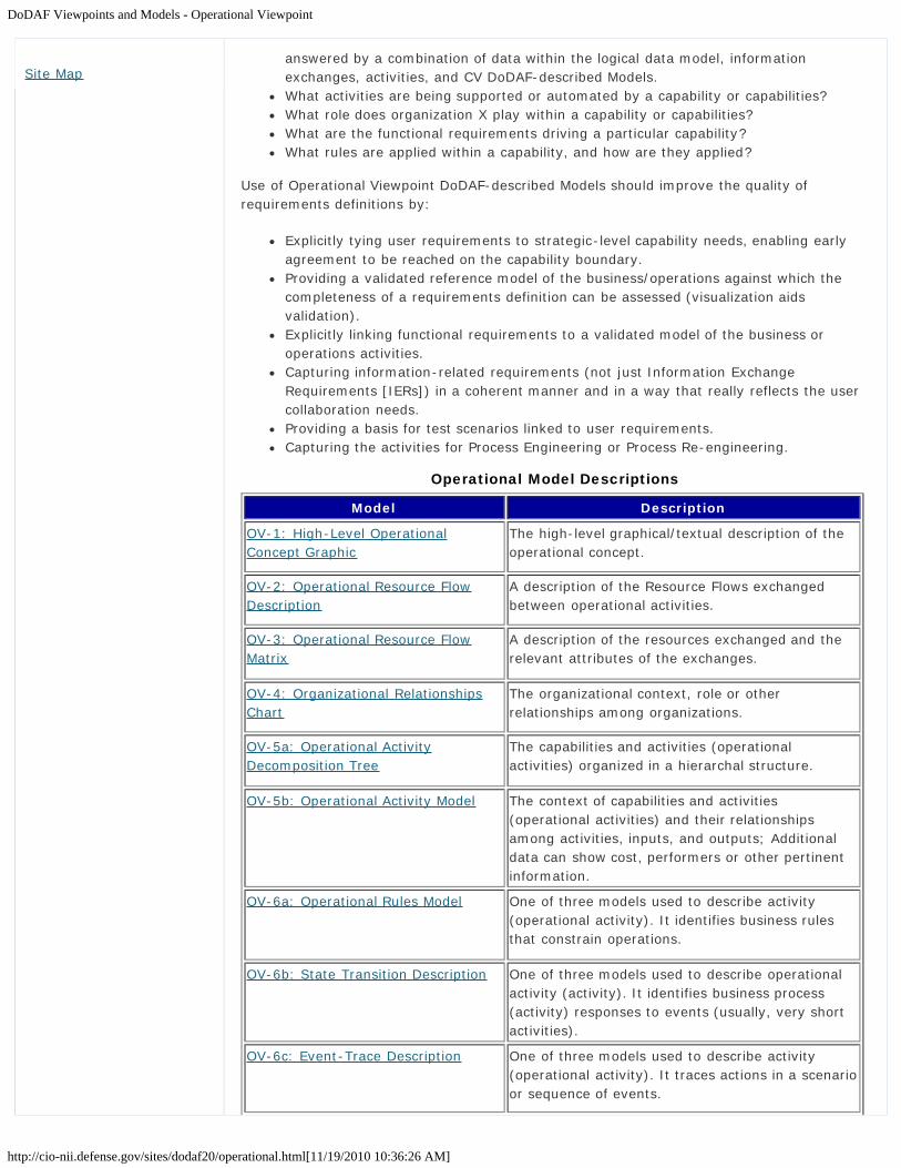
DoDAF Viewpoints and Models - Operational Viewpoint
http://cio-nii.defense.gov/sites/dodaf20/operational.html[11/19/2010 10:36:26 AM]
answered by a combination of data within the logical data model, informationexchanges, activities, and CV DoDAF-described Models.What activities are being supported or automated by a capability or capabilities?What role does organization X play within a capability or capabilities?What are the functional requirements driving a particular capability?What rules are applied within a capability, and how are they applied?
Use of Operational Viewpoint DoDAF-described Models should improve the quality ofrequirements definitions by:
Explicitly tying user requirements to strategic-level capability needs, enabling earlyagreement to be reached on the capability boundary.Providing a validated reference model of the business/operations against which thecompleteness of a requirements definition can be assessed (visualization aidsvalidation).Explicitly linking functional requirements to a validated model of the business oroperations activities.Capturing information-related requirements (not just Information ExchangeRequirements [IERs]) in a coherent manner and in a way that really reflects the usercollaboration needs.Providing a basis for test scenarios linked to user requirements.Capturing the activities for Process Engineering or Process Re-engineering.
Operational Model Descriptions
Model Description
OV-1: High-Level OperationalConcept Graphic
The high-level graphical/textual description of theoperational concept.
OV-2: Operational Resource FlowDescription
A description of the Resource Flows exchangedbetween operational activities.
OV-3: Operational Resource FlowMatrix
A description of the resources exchanged and therelevant attributes of the exchanges.
OV-4: Organizational RelationshipsChart
The organizational context, role or otherrelationships among organizations.
OV-5a: Operational ActivityDecomposition Tree
The capabilities and activities (operationalactivities) organized in a hierarchal structure.
OV-5b: Operational Activity Model The context of capabilities and activities(operational activities) and their relationshipsamong activities, inputs, and outputs; Additionaldata can show cost, performers or other pertinentinformation.
OV-6a: Operational Rules Model One of three models used to describe activity(operational activity). It identifies business rulesthat constrain operations.
OV-6b: State Transition Description One of three models used to describe operationalactivity (activity). It identifies business process(activity) responses to events (usually, very shortactivities).
OV-6c: Event-Trace Description One of three models used to describe activity(operational activity). It traces actions in a scenarioor sequence of events.
Site Map

DoDAF Viewpoints and Models - Operational Viewpoint
http://cio-nii.defense.gov/sites/dodaf20/operational.html[11/19/2010 10:36:26 AM]
Mappings of the Data and Information Viewpoint DoDAF-described Models to the DM2Concepts, Associations, and Attributes are in DM2 Concepts, Associations, andAttributes Mapping to DoDAF-described Models. The DM2 Concepts, Associations, andAttributes are described in the DoDAF Meta-model Data Dictionary.
Go to top of page ?
Privacy Policy | Web Policy | Contact | Submit Change Requests

OV-1: High Level Operational Concept Graphic
http://cio-nii.defense.gov/sites/dodaf20/OV-1.html[11/18/2010 12:10:21 PM]
Home DoDAF-DM2 WG DoDAF Journal DoD Meta Data Registry IDEAS Links
DoDAF Viewpoints and Models
Operational Viewpoint
OV-1: High Level Operational Concept Graphic
The OV-1 describes a mission, class of mission, or scenario. It shows the main operationalconcepts and interesting or unique aspects of operations. It describes the interactionsbetween the subject architecture and its environment, and between the architecture andexternal systems. The OV-1 is the pictorial representation of the written content of the AV-1Overview and Summary Information. Graphics alone are not sufficient for capturing thenecessary architectural data.
The OV-1 provides a graphical depiction of what the architecture is about and an idea of theplayers and operations involved. An OV-1 can be used to orient and focus detaileddiscussions. Its main use is to aid human communication, and it is intended for presentationto high-level decision-makers.
The intended usage of the OV-1 includes:
Putting an operational situation or scenario into context.Providing a tool for discussion and presentation; for example, aids industryengagement in acquisition.Providing an aggregate illustration of the details within the published high-levelorganization of more detailed information in published architectures.
Detailed Description:
Each Operational Viewpoint relates to a specific point within the Enterprise's timeline. TheOV-1 describes a mission, class of mission, or scenario. The purpose of OV-1 is to provide aquick, high-level description of what the architecture is supposed to do, and how it issupposed to do it. An OV-1 can be used to orient and focus detailed discussions. Its mainutility is as a facilitator of human communication, and it is intended for presentation to high-level decision-makers. An OV-1 identifies the mission/scope covered in the ArchitecturalDescription. OV-1 conveys, in simple terms, what the Architectural Description is about andan idea of the players and operations involved.
The content of an OV-1 depends on the scope and intent of the Architectural Description, butin general it describes the business activities or missions, high-level operations,organizations, and geographical distribution of assets. The model frames the operationalconcept (what happens, who does what, in what order, to accomplish what goal) andhighlight interactions to the environment and other external systems. However, the contentis at an executive summary-level as other models allow for more detailed definition ofinteractions and sequencing.
It may highlight the key Operational concepts and interesting or unique aspects of theconcepts of operations. It provides a description of the interactions between the ArchitecturalDescription and its environment, and between the Architectural Description and externalsystems. A textual description accompanying the graphic is crucial. Graphics alone are notsufficient for capturing the necessary architectural data.
The OV-1 consists of a graphical executive summary for a given Architectural Descriptionwith accompanying text.
Introduction
What is New in DoDAF V2.0
Vision for DoDAF V2.0
Architecture Resources
DoDAF V1.5 Support
Relationships to otherFrameworks
Background
Architecture Development
Viewpoints
All Viewpoint
Capability Viewpoint
Data and InformationViewpoint
Operational Viewpoint
Project Viewpoint
Services Viewpoint
Standards Viewpoint
Systems Viewpoint
Models
DM2
Manager Role
Architect Role
Developer Role
Department of Defense

OV-1: High Level Operational Concept Graphic
http://cio-nii.defense.gov/sites/dodaf20/OV-1.html[11/18/2010 12:10:21 PM]
During the course of developing an Architectural Description, several versions of an OV-1may be produced. An initial version may be produced to focus the effort and illustrate itsscope. After other models within the Architectural Description's scope have been developedand verified, another version of the OV-1 may be produced to reflect adjustments to thescope and other Architectural Description details that may have been identified as a result ofthe architecture development. After the Architectural Description has been used for itsintended purpose and the appropriate analysis has been completed, yet another version maybe produced to summarize these findings to present them to high-level decision-makers. Inother cases, OV-1 is the last model to be developed, as it conveys summary informationabout the whole Architectural Description for a given scenario.
The OV-1 is useful in establishing the context for a suite of related operational models. Thiscontext may be in terms of phase, a time period, a mission and/or a location. In particular,this provides a container for the spatial-temporally constrained performance parameters(measures).
To describe this, the operational performance measures for desert warfare in Phase 1 may bedifferent to those in Phase 2. The measures for jungle warfare in Phase 2 may be different tothose for desert warfare in Phase 2.
The context may also explicitly involve a Mission. When the subject of the ArchitecturalDescription is a business capability rather than a battlespace capability, then someadjustment is needed in the use of terminology. However, the idea of having a high-level(Business) operational concept still makes sense and the graphical representation in OV-1adds value to the more structured models that may be created.
OV-1 is the most general of the architectural models and the most flexible in format.However, an OV-1 usually consists of one or more graphics (or possibly a video-clip), asneeded, as well as explanatory text.
OV-1: High-Level Operational Concept Graphic
OV-2: Operational Resource Flow Description
OV-3: Operational Resource Flow Matrix
OV-4: Organizational Relationships Chart
OV-5a: Operational Activity Decomposition Tree
OV-5b: Operational Activity Model
OV-6a, 6b, 6c: Introduction
OV-6a: Operational Rules Model
OV-6b: State Transition Description
OV-6c: Event-Trace Description
Go to top of page ?
Site Map
Privacy Policy | Web Policy | Contact | Submit Change Requests

OV-2: Operational Resource Flow Description
http://cio-nii.defense.gov/sites/dodaf20/OV-2.html[11/18/2010 12:10:31 PM]
Home DoDAF-DM2 WG DoDAF Journal DoD Meta Data Registry IDEAS Links
DoDAF Viewpoints and Models
Operational Viewpoint
OV-2: Operational Resource Flow Description
The OV-2 DoDAF-described Model applies the context of the operational capability to acommunity of anticipated users. The primary purpose of the OV-2 is to define capabilityrequirements within an operational context. The OV-2 may also be used to express acapability boundary.
New to DoDAF V2.0, the OV-2 can be used to show flows of funding, personnel and materielin addition to information. A specific application of the OV-2 is to describe a logical patternof resource (information, funding, personnel, or materiel) flows. The logical pattern need notcorrespond to specific organizations, systems or locations, allowing Resource Flows to beestablished without prescribing the way that the Resource Flows are handled and withoutprescribing solutions.
The intended usage of the OV-2 includes:
Definition of operational concepts.Elaboration of capability requirements.Definition of collaboration needs.Applying a local context to a capability.Problem space definition.Operational planning.Supply chain analysis.Allocation of activities to resources.
Detailed Description:
The OV-2 depicts Operational Needlines that indicate a need to exchange resources. New toDoDAF V2.0, the OV-2 show flows of funding, personnel and materiel in addition toinformation. The OV-2 may also show the location of Operational facilities or locations, andmay optionally be annotated to show flows of information, funding, people or materielbetween Operational Activities. The Operational Activities shown in an OV-2 may be internalto the architecture, or may be external activities that communicate with those internalactivities.
Use of OV-2 is intended to be logical. It is to describe who or what, not how. This modelprovides a focus for the operational requirements which may reflect any capabilityrequirements that have been articulated but within the range of operational settings that arebeing used for operational architecture. In an "As-Is" architecture, an OV-2 may be used asan abstract (i.e., simplified) representation of the Resource Flows taking place in theEnterprise. An OV-2 can be a powerful way of expressing the differences between an "As-Is"Architectural Description and a proposed "To-Be" Architectural Description to non-technicalstakeholders, as it simply shows how Resource Flows (or does not flow). The aim of the OV-2 is to record the operational characteristics for the community of anticipated users relevantto the Architectural Description and their collaboration needs, as expressed in Needlines andResource Flows.
A specific application of the OV-2 is to describe a logical pattern of resource (information,funding, personnel, or materiel) flows. The purpose of an OV-2 model is to describe a logical
Introduction
What is New in DoDAF V2.0
Vision for DoDAF V2.0
Architecture Resources
DoDAF V1.5 Support
Relationships to otherFrameworks
Background
Architecture Development
Viewpoints
All Viewpoint
Capability Viewpoint
Data and InformationViewpoint
Operational Viewpoint
Project Viewpoint
Services Viewpoint
Standards Viewpoint
Systems Viewpoint
Models
DM2
Manager Role
Architect Role
Developer Role
Department of Defense

OV-2: Operational Resource Flow Description
http://cio-nii.defense.gov/sites/dodaf20/OV-2.html[11/18/2010 12:10:31 PM]
pattern of Resource Flows. The logical pattern need not correspond to specific organizations,systems or locations, allowing Resource Flows to be established without prescribing the waythat the Resource Flows are handled and without prescribing solutions. The OV-2 is intendedto track the need for Resource Flows between specific Operational Activities and Locationsthat play a key role in the Architectural Description. OV-2 does not depict the physicalconnectivity between the Activities and Locations. The logical pattern established in an OV-2model may act as the backbone onto which architectural elements may be overlaid - e.g., aSV-1 Systems Interface Description model can show which systems are providing thenecessary capability.
The main features of this model are the Operational Resource Flows, and the location (ortype of location/environment) where the resources need to be or are deployed, and theNeedlines that indicate a need to exchange or share resources. An OV-2 indicates the keyplayers and the interactions necessary to conduct the corresponding operational activities ofOV-5a Operational Activity Decomposition Tree or OV-5b Operational Activity Model.
A Needline documents the required or actual exchanges of resources. A Needline is a conduitfor one or more resource exchanges - i.e., it represents a logical bundle of Resource Flows.The Needline does not indicate how the transfer is implemented. For example, if information(or funding, personnel, or materiel) is produced at location A, routed through location B, andis used at location C, then location B would not be shown on the OV-2 - the Needline wouldgo from Location A to Location C. The OV-2 is not a communications link or communicationsnetwork diagram but a high-level definition of the logical requirement for resource exchange.
A OV-2 can also define a need to exchange items between Operational Activities andlocations and external resources (i.e., Operational Activities, Locations, or Organizations thatare not strictly within the scope of the subject Architectural Description but which interfaceto it either as important sources of items required within the Architectural Description orimportant destinations for items provided within the Architectural Description).
The OV-2 is intended to track the need to exchange items between key OperationalActivities and Locations within the Architectural Description. The OV-2 does not depict thephysical connectivity between the Operational Activities and Locations. The Needlinesestablished in an OV-2 can be realized by resources and their interactions in a SV-1 SystemsInterface Description model or SvcV-1 Services Context Description model. There may not bea one-to-one correspondence between an operational activity and a location in OV-2 and aresource in SV-1 Systems Interface Description model or SvcV-1 Services ContextDescription model. For example, an Operational Activity and location may be realized by twosystems, where one provides backup for the other, or it may be that the functionality of anOperational Activity has to be split between two locations for practical reasons.
Needlines can be represented by arrows (indicating the direction of flow) and are annotatedwith a diagram-unique identifier and a phrase that is descriptive of the principal type ofexchange - it may be convenient to present these phrases (or numerical labels) in a key tothe diagram to prevent cluttering. It is important to note that the arrows (with identifiers) onthe diagram represent Needlines only. This means that each arrow indicates only that thereis a need for the transfer of some resource between the two connected Activities orlocations. A Needline can be uni-directional. Because Needline identifiers are often needed toprovide a trace reference for Resource Flow requirements (see OV-3 Operational ResourceFlow Matrix), a combined approach, with numerical and text labels, can be used.
There may be several Needlines (in the same direction) from one resource to another. Thismay occur because some Needlines are only relevant to certain scenarios, missions ormission phases. In this case, when producing the OV-2 for the specific case, a subset of allof the Needlines should be displayed. There can be a one-to-many relationship fromNeedlines to Resource Flow (e.g., a single Needline in OV-2 represents multiple individualResource Flows). The mapping of the Resource Flows to the Needlines of OV-2 occurs in theOperational Resource Flow Matrix (OV-3). For example, OV-2 may list Situation Report as adescriptive name for a Needline between two Operational resources. In this case, theNeedline represents a number of resource flow (information in this case) exchanges,
Site Map

OV-2: Operational Resource Flow Description
http://cio-nii.defense.gov/sites/dodaf20/OV-2.html[11/18/2010 12:10:31 PM]
consisting of various types of reports (information elements), and their attributes (such asperiodicity and timeliness) that are associated with the Situation Report Needline. Theidentity of the individual elements and their attributes are documented in OV-3 OperationalResource Flow Matrix model.
For complex Architectural Descriptions, OV-2 may consist of multiple graphics. There areseveral different ways to decompose OV-2. One method involves using multiple levels ofabstraction and decomposing the Resource Flows. Another method involves restricting theResource Flows and Needlines on any given graphic to those associated with a subset ofoperational activities. Finally it is possible to organize OV-2 in terms of scenarios, missions ormission phases. All of these methods are valid and can be used together.
Flows of Funding, Personnel and Material:
In addition to Needlines, Resource Flow Connectors can be used to overlay contextualinformation about how the Operational Activities and Locations interact via physical flows.This information helps to provide context for the business roles. Examples of Resource FlowConnector usage would be:
Representing a logistics capability may have an interaction which involves supplying(physically delivering) personnel.Representing an air-to-air refueling capability may have an interaction with airborneplatform capabilities which involves transfer of fuel.Representing a sensor capability may have an interaction with a target through a flowof physical energy that is sensed; this is not an information flow.
This is achieved by overlaying the Resource Flow Connectors on the diagram using anotation that is clearly distinct from Needlines (which only represent the requirement to flowresources).
Operational Activities:
The operational activities (from the OV-5b Operational Activity Model) performed may belisted on the graphic, if space permits. OV-2 and the OV-5b Operational Activity Model arecomplementary descriptions. OV-2 focuses on the Operational Resource Flows, with theactivities being a secondary adornment. The OV-5b, on the other hand, places first-orderattention on operational activities and only second-order attention on Resource Flows, whichcan be shown as annotations or swim lanes on the activities. In developing an ArchitecturalDescription, OV-2 and OV-5b Operational Activity Model are often the starting points andthese may be developed iteratively.
OV-1: High-Level Operational Concept Graphic
OV-2: Operational Resource Flow Description
OV-3: Operational Resource Flow Matrix
OV-4: Organizational Relationships Chart
OV-5a: Operational Activity Decomposition Tree
OV-5b: Operational Activity Model
OV-6a, 6b, 6c: Introduction
OV-6a: Operational Rules Model
OV-6b: State Transition Description
OV-6c: Event-Trace Description
Go to top of page ?

OV-2: Operational Resource Flow Description
http://cio-nii.defense.gov/sites/dodaf20/OV-2.html[11/18/2010 12:10:31 PM]
Privacy Policy | Web Policy | Contact | Submit Change Requests

OV-3: Operational Resource Flow Matrix
http://cio-nii.defense.gov/sites/dodaf20/OV-3.html[11/18/2010 12:10:43 PM]
Home DoDAF-DM2 WG DoDAF Journal DoD Meta Data Registry IDEAS Links
DoDAF Viewpoints and Models
Operational Viewpoint
OV-3: Operational Resource Flow Matrix
The OV-3 addresses operational Resource Flows exchanged between Operational Activitiesand locations.
Resource Flows provide further detail of the interoperability requirements associated with theoperational capability of interest. The focus is on Resource Flows that cross the capabilityboundary.
The intended usage of the OV-3 includes:
. Definition of interoperability requirements.
Detailed Description:
The OV-3 identifies the resource transfers that are necessary to support operations toachieve a specific operational task. This model is initially constructed from the informationcontained in the OV-2 Operational Resource Flow Description model. But the OV-3 providesa more detailed definition of the Resource Flows for operations within a community ofanticipated users.
The Operational Resource Flow Matrix details Resource Flow exchanges by identifying whichOperational Activity and locations exchange what resources, with whom, why the resource isnecessary, and the key attributes of the associated resources. The OV-3 identifies resourceelements and relevant attributes of the Resource Flows and associates the exchange to theproducing and consuming Operational Activities and locations and to the Needline that theResource Flow satisfies. OV-3 is one of a suite of operational models that address theresource content of the operational architecture (the others being OV-2 Operational ResourceFlow Description, OV-5b Operational Activity Model, and DIV-2 Logical Data Model).Needlines are logical requirements-based collaboration relationships between OperationalActivities and locations (as shown in OV-2 Operational Resource Flow Description). ANeedline can be uni-directional.
A resource element (see DIV-2 Logical Data Model) is a formalized representation ofResource Flows subject to an operational process. Resource elements may mediate activityflows and dependencies (see OV-5b Operational Activity Model). Hence they may also becarried by Needlines that express collaboration relationships. The same resource elementmay be used in one or more Resource Flows.
The emphasis in this model is on the logical and operational characteristics of the ResourceFlows being exchanged, with focus on the Resource Flows crossing the capability boundary.It is important to note that OV-3 is not intended to be an exhaustive listing of all the detailscontained in every Resource Flow of every Operational Activity and location associated withthe Architectural Description in question. Rather, this model is intended to capture the mostimportant aspects of selected Resource Flows.
The aspects of the Resource Flow that are crucial to the operational mission will be trackedas attributes in OV-3. For example, if the subject Architectural Description concerns tacticalbattlefield targeting, then the timeliness of the enemy target information is a significantattribute of the Resource Flow. To support the needs of security architecture, Resource Flowsshould also address criticality and classification. There is an important caveat on use of OV-3
Introduction
What is New in DoDAF V2.0
Vision for DoDAF V2.0
Architecture Resources
DoDAF V1.5 Support
Relationships to otherFrameworks
Background
Architecture Development
Viewpoints
All Viewpoint
Capability Viewpoint
Data and InformationViewpoint
Operational Viewpoint
Project Viewpoint
Services Viewpoint
Standards Viewpoint
Systems Viewpoint
Models
DM2
Manager Role
Architect Role
Developer Role
Department of Defense

OV-3: Operational Resource Flow Matrix
http://cio-nii.defense.gov/sites/dodaf20/OV-3.html[11/18/2010 12:10:43 PM]
for security architectures. In that context, it is important to identify every possible andrequired exchange.
There is not always a one-to-one mapping of OV-3 Resource Flows to OV-2 OperationalResource Flow Description Needlines; rather, many individual Resource Flows may beassociated with one Needline.
The OV-3 information can be presented in tabular form. DoDAF V2.0 does not prescribe thecolumn headings in an OV-3 Matrix.
OV-1: High-Level Operational Concept Graphic
OV-2: Operational Resource Flow Description
OV-3: Operational Resource Flow Matrix
OV-4: Organizational Relationships Chart
OV-5a: Operational Activity Decomposition Tree
OV-5b: Operational Activity Model
OV-6a, 6b, 6c: Introduction
OV-6a: Operational Rules Model
OV-6b: State Transition Description
OV-6c: Event-Trace Description
Go to top of page ?
Site Map
Privacy Policy | Web Policy | Contact | Submit Change Requests

OV-4: Organizational Relationships Chart
http://cio-nii.defense.gov/sites/dodaf20/OV-4.html[11/18/2010 12:10:54 PM]
Home DoDAF-DM2 WG DoDAF Journal DoD Meta Data Registry IDEAS Links
DoDAF Viewpoints and Models
Operational Viewpoint
OV-4: Organizational Relationships Chart
The OV-4 shows organizational structures and interactions. The organizations shown may becivil or military. The OV-4 exists in two forms; role-based (e.g., a typical brigade commandstructure) and actual (e.g., an organization chart for a department or agency).
A role-based OV-4 shows the possible relationships between organizational resources. Thekey relationship is composition, i.e., one organizational resource being part of a parentorganization. In addition to this, the architect may show the roles each organizationalresource has, and the interactions between those roles, i.e., the roles represent thefunctional aspects of organizational resources. There are no prescribed resource interactionsin DoDAF V2.0: the architect should select an appropriate interaction type from the DM2 oradd a new one. Interactions illustrate the fundamental roles and managementresponsibilities, such as supervisory reporting, Command and Control (C2) relationships,collaboration and so on.
An actual OV-4 shows the structure of a real organization at a particular point in time, and isused to provide context to other parts of the architecture such as AV-1 and the CVs.
The intended usage of the role-based OV-4 includes:
Organizational analysis.Definition of human roles.Operational analysis.
The intended usage of the actual OV-4 includes:
Identify architecture stakeholders.Identify process owners.Illustrate current or future organization structures.
Detailed Description:
The OV-4 addresses the organizational aspects of an Architectural Description. A typical OV-4 illustrates the command structure or relationships (as opposed to relationships withrespect to a business process flow) among human roles, organizations, or organization typesthat are the key players in the business represented by the architecture. An actual OV-4shows real organizations and the relationships between them.
The more commonly used types of organizational relationship will be defined, in time, in theDoDAF Meta-model. DoDAF defines fundamental relationships between OrganizationalResources; including structure (whole-part) and interaction. The interaction relationshipcovers most types of organizational relationship. An OV-4 clarifies the various relationshipsthat can exist between organizations and sub-organizations within the ArchitecturalDescription and between internal and external organizations. Where there is a need for othertypes of organizational relationships, these should be recorded and defined in the AV-2Integrated Dictionary as extensions to the DM2.
Organizational relationships are important to depict in an architecture model, because theycan illustrate fundamental human roles (e.g., who or what type of skill is needed to conduct
Introduction
What is New in DoDAF V2.0
Vision for DoDAF V2.0
Architecture Resources
DoDAF V1.5 Support
Relationships to otherFrameworks
Background
Architecture Development
Viewpoints
All Viewpoint
Capability Viewpoint
Data and InformationViewpoint
Operational Viewpoint
Project Viewpoint
Services Viewpoint
Standards Viewpoint
Systems Viewpoint
Models
DM2
Manager Role
Architect Role
Developer Role
Department of Defense

OV-4: Organizational Relationships Chart
http://cio-nii.defense.gov/sites/dodaf20/OV-4.html[11/18/2010 12:10:54 PM]
operational activities) as well as management relationships (e.g., command structure orrelationship to other key players). Also, organizational relationships are drivers for some ofthe collaboration requirements that are viewed using Needlines.
Note that individual people are not viewed in DoDAF, but specific billets or Person Types maybe detailed in an actual OV-4.
In both the typical and specific cases, it is possible to overlay resource interactionrelationships which denote relationships between organizational elements that are not strictlyhierarchical (e.g., a customer-supplier relationship).
The organizations that are modeled using OV-4 may also appear in other models, forexample in the SV-1 Systems Interface Description as organizational constituents of acapability or a resource and PV-1 Project Portfolio Relationships where organizations ownprojects. In a SV-1 Systems Interface Description, for instance, the organizational resourcesdefined in a typical OV-4 may be part of a capability or resources. Also, actual organizationsmay form elements of a fielded capability which realizes the requirements at the system-level (again, this may be depicted on a SV-1 Systems Interface Description).
A OV-4 may show types of organizations and the typical structure of those organizations.The OV-4 may alternatively show actual, specific organizations (e.g., the DoD) at some pointin time. Alternatively, an OV-4 may be a hybrid diagram showing typical and actualorganization structures.
OV-1: High-Level Operational Concept Graphic
OV-2: Operational Resource Flow Description
OV-3: Operational Resource Flow Matrix
OV-4: Organizational Relationships Chart
OV-5a: Operational Activity Decomposition Tree
OV-5b: Operational Activity Model
OV-6a, 6b, 6c: Introduction
OV-6a: Operational Rules Model
OV-6b: State Transition Description
OV-6c: Event-Trace Description
Go to top of page ?
Site Map
Privacy Policy | Web Policy | Contact | Submit Change Requests

OV-5a: Operational Activity Decomposition Tree and OV-5b: Operational Activity Model
http://cio-nii.defense.gov/sites/dodaf20/OV-5ab.html[11/18/2010 12:11:03 PM]
Home DoDAF-DM2 WG DoDAF Journal DoD Meta Data Registry IDEAS Links
DoDAF Viewpoints and Models
Operational Viewpoint
OV-5a: Operational Activity Decomposition Tree and OV-5b: Operational ActivityModel
The OV-5a and the OV-5b describe the operations that are normally conducted in the courseof achieving a mission or a business goal. It describes operational activities (or tasks);Input/Output flows between activities, and to/from activities that are outside the scope ofthe Architectural Description.
The OV-5a and OV-5b describes the operational activities that are being conducted withinthe mission or scenario. The OV-5a and OV-5b can be used to:
Clearly delineate lines of responsibility for activities when coupled with OV-2.Uncover unnecessary Operational Activity redundancy.Make decisions about streamlining, combining, or omitting activities.Define or flag issues, opportunities, or operational activities and their interactions(information flows among the activities) that need to be scrutinized further.Provide a necessary foundation for depicting activity sequencing and timing in the OV-6a Operational Rules Model, the OV-6b State Transition Description, and the OV-6cEvent-Trace Description.
The OV-5b describes the operational, business, and defense portion of the intelligencecommunity activities associated with the Architectural Description, as well as the:
Relationships or dependencies among the activities.Resources exchanged between activities.External interchanges (from/to business activities that are outside the scope of themodel).
An Operational Activity is what work is required, specified independently of how it is carriedout. To maintain this independence from implementation, logical activities and locations inOV-2 Operational Resource Flow Description are used to represent the structure whichcarries out the Operational Activities. Operational Activities are realized as System Functions(described in SV-4 Systems Functionality Description) or Service Functions (described inSvcV-4 Services Functionality Description) which are the how to the Operational Activitieswhat, i.e., they are specified in terms of the resources that carry them out.
The intended usage of the OV-5a and OV-5b includes:
Description of activities and workflows.Requirements capture.Definition of roles and responsibilities.Support task analysis to determine training needs.Problem space definition.Operational planning.Logistic support analysis.Information flow analysis.
Detailed Description:
Introduction
What is New in DoDAF V2.0
Vision for DoDAF V2.0
Architecture Resources
DoDAF V1.5 Support
Relationships to otherFrameworks
Background
Architecture Development
Viewpoints
All Viewpoint
Capability Viewpoint
Data and InformationViewpoint
Operational Viewpoint
Project Viewpoint
Services Viewpoint
Standards Viewpoint
Systems Viewpoint
Models
DM2
Manager Role
Architect Role
Developer Role
Department of Defense

OV-5a: Operational Activity Decomposition Tree and OV-5b: Operational Activity Model
http://cio-nii.defense.gov/sites/dodaf20/OV-5ab.html[11/18/2010 12:11:03 PM]
The OV-5s and OV-2 Operational Resource Flow Description model are, to a degree,complements of each other. The OV-5s focuses on the operational activities whereas OV-2Operational Resource Flow Description model focuses on the operational activities in relationto locations. Due to the relationship between locations and operational activities, these typesof models should normally be developed together. An OV-5a or OV-5b describes theoperational activites (or tasks) that are normally conducted in the course of achieving amission or a business goal. The OV-5b also describes Input/Output flows between activities,and to/from activities that are outside the scope of the Architectural Description. The OV-5aand OV-5b are equally suited to describing non-military activities and are expected to beused extensively for business modeling.
The activities described in an OV-5a or OV-5b are standard Operational Activities which aremapped to corresponding capabilities in the CV-6 Capability to Operational ActivitiesMapping. Standard Operational Activities are those defined in doctrine, but which are nottailored to a specific system, i.e., they are generic enough to be used without closing off arange of possible solutions.
Possible Construction Methods: DoDAF does not endorse a specific activity modelingmethodology. The OV-5b can be constructed using Integration Definition for FunctionModeling (IDEF0) or Class Diagrams.
There are two basic ways to depict Activity Models:
The Activity Decomposition Tree shows activities depicted in a tree structure and istypically used to provide a navigation aid.The Activity Model shows activities connected by Resource Flows; it supportsdevelopment of an OV-3 Operational Resource Flow Matrix.
The OV-5a helps provide an overall picture of the activities involved and a quick referencefor navigating the OV-5b.
OV-1: High-Level Operational Concept Graphic
OV-2: Operational Resource Flow Description
OV-3: Operational Resource Flow Matrix
OV-4: Organizational Relationships Chart
OV-5a: Operational Activity Decomposition Tree
OV-5b: Operational Activity Model
OV-6a, 6b, 6c: Introduction
OV-6a: Operational Rules Model
OV-6b: State Transition Description
OV-6c: Event-Trace Description
Go to top of page ?
Site Map
Privacy Policy | Web Policy | Contact | Submit Change Requests

OV-6a, 6b, 6c: Introduction
http://cio-nii.defense.gov/sites/dodaf20/OV-6introduction.html[11/18/2010 12:11:15 PM]
Home DoDAF-DM2 WG DoDAF Journal DoD Meta Data Registry IDEAS Links
DoDAF Viewpoints and Models
Operational Viewpoint
Introduction to OV-6a, OV-6b and OV-6c
OV Models discussed in previous sections model the static structure of the Architecturalelements and their relationships. Many of the critical characteristics of an architecture areonly discovered when the dynamic behavior of these elements is modeled to incorporatesequencing and timing aspects.
The dynamic behavior referred to here concerns the timing and sequencing of events thatcapture operational behavior of a business process or mission thread. Thus, this behavior isrelated to the activities of OV-5b. Behavior modeling and documentation is essential to asuccessful Architectural Description, because it describes how the architecture behaves andthat is crucial in many situations. Knowledge of the Operational Activities and Resource Flowexchanges is important; but knowing when, for example, a response should be expectedafter sending message X to Activity Y at Location A can also be essential to achievingsuccessful operations.
Several modeling techniques may be used to refine and extend the ArchitecturalDescription's OV to adequately describe the dynamic behavior and timing performancecharacteristics of an architecture. The OV-6 DoDAF-described Models includes three suchmodels. They are:
Operational Rules Model (OV-6a)Operational State Transition Description (OV-6b)Operational Event-Trace Description (OV-6c)
OV-6 DoDAF-described Models portray some of the same architectural data elements, buteach also portrays some unique architectural data elements. OV-6b and OV-6c may be usedseparately or together, as necessary, to describe critical timing and sequencing behavior inthe OV. Both types of models are used by a wide variety of business process methodologiesas well as Object-Oriented methodologies. OV-6b and OV-6c describe Operational Activity orbusiness process responses to sequences of events. Events may also be referred to asinputs, transactions, or triggers. Events can be internally or externally generated and caninclude such things as the receipt of a message, a timer going off, or conditional tests beingsatisfied. When an event occurs, the action to be taken may be subject to a rule or set ofrules (conditions) as described in OV-6a.
OV-1: High-Level Operational Concept Graphic
OV-2: Operational Resource Flow Description
OV-3: Operational Resource Flow Matrix
OV-4: Organizational Relationships Chart
OV-5a: Operational Activity Decomposition Tree
OV-5b: Operational Activity Model
OV-6a, 6b, 6c: Introduction
OV-6a: Operational Rules Model
Introduction
What is New in DoDAF V2.0
Vision for DoDAF V2.0
Architecture Resources
DoDAF V1.5 Support
Relationships to otherFrameworks
Background
Architecture Development
Viewpoints
All Viewpoint
Capability Viewpoint
Data and InformationViewpoint
Operational Viewpoint
Project Viewpoint
Services Viewpoint
Standards Viewpoint
Systems Viewpoint
Models
DM2
Manager Role
Architect Role
Developer Role
Department of Defense

OV-6a, 6b, 6c: Introduction
http://cio-nii.defense.gov/sites/dodaf20/OV-6introduction.html[11/18/2010 12:11:15 PM]
OV-6b: State Transition Description
OV-6c: Event-Trace Description
Go to top of page ?
Site Map
Privacy Policy | Web Policy | Contact | Submit Change Requests

OV-6a: Operational Rules Model
http://cio-nii.defense.gov/sites/dodaf20/OV-6a.html[11/18/2010 12:11:25 PM]
Home DoDAF-DM2 WG DoDAF Journal DoD Meta Data Registry IDEAS Links
DoDAF Viewpoints and Models
Operational Viewpoint
OV-6a: Operational Rules Model
An OV-6a specifies operational or business rules that are constraints on the way thatbusiness is done in the enterprise. At a top-level, rules should at least embody the conceptsof operations defined in OV-1 High Level Operational Concept Graphic and provide guidelinesfor the development and definition of more detailed rules and behavioral definitions thatshould occur later in the Architectural definition process.
The intended usage of the OV-6a includes:
Definition of doctrinally correct operational procedures.Definition of business rules.Identification of operational constraints.
Detailed Description:
The OV-6a specifies operational or business rules that are constraints on the way business isdone in the enterprise. While other OV Models (e.g., OV-1 High Level Operational ConceptGraphic, OV-2 Operational Resource Flow Description, and OV-5b Operational Activity Model)describe the structure and operation of a business, for the most part they do not describethe constraints and rules under which it operates.
At the mission-level, OV-6a may be based on business rules contained in doctrine, guidance,rules of engagement, etc. At lower levels, OV-6a describes the rules under which thearchitecture behave under specified conditions. Such rules can be expressed in a textualform, for example, If (these conditions) exist, and (this event) occurs, then (perform theseactions). These rules are contrasted with the business or doctrinal standards themselves,which provide authoritative references and provenance for the rules (see StdV-1 StandardsProfile). Operational Rules are statements that constrain some aspect of the mission or thearchitecture. Rules may be expressed in natural language (English) in one of two forms:
Imperative - a statement of what shall be under all conditions, e.g., "Battle DamageAssessment (BDA) shall only be carried out under fair weather conditions."Conditional Imperative - a statement of what shall be, in the event of anothercondition being met. If battle damage assessment shows incomplete strike, then a re-strike shall be carried out.
As the model name implies, the rules captured in OV-6a are operational (i.e., mission-oriented) whereas resource-oriented rules are defined in the SV-10s or the SvcV-10s (OV-6is the what to the SV-10's or SvcV-10's how). OV-6a rules can include such guidance as theconditions under which operational control passes from one entity to another or theconditions under which a human role is authorized to proceed with a specific activity.
A rule defined in textual form OV-6a may be applied to any Architectural element defined inan OV. A rule defined in a more structured way (i.e., for the purposes of sharing with otherarchitects) should be defined in association with locations, operational activities or missions.
Rules defined in an OV-6a may optionally be presented in any other OV. For example, a rule"battle damage assessment shall be carried out under fair weather conditions" may be linked
Introduction
What is New in DoDAF V2.0
Vision for DoDAF V2.0
Architecture Resources
DoDAF V1.5 Support
Relationships to otherFrameworks
Background
Architecture Development
Viewpoints
All Viewpoint
Capability Viewpoint
Data and InformationViewpoint
Operational Viewpoint
Project Viewpoint
Services Viewpoint
Standards Viewpoint
Systems Viewpoint
Models
DM2
Manager Role
Architect Role
Developer Role
Department of Defense

OV-6a: Operational Rules Model
http://cio-nii.defense.gov/sites/dodaf20/OV-6a.html[11/18/2010 12:11:25 PM]
to the Conduct BDA activity in OV-5b. Any natural language rule presented (e.g., in adiagram note) should also be listed in OV-6a.
OV-6a rules may be associated with activities in OV-5a Operational Activity DecompositionTree and OV-5b Operational Activity Model and can be useful to overlay the rules on an OV-5a Operational Activity Decomposition or OV-5b Operational Activity Model. OV-6a can alsobe used to extend the capture of business requirements by constraining the structure andvalidity of DIV-2 Logical Data Model elements.
Detailed rules can become quite complex, and the structuring of the rules themselves canoften be challenging. DoDAF does not specify how OV-6a rules will be specified, other than inEnglish.
From a modeling perspective, operational constraints may act upon Locations, OperationalActivities, Missions, and Entities in Logical Data Models.
OV-1: High-Level Operational Concept Graphic
OV-2: Operational Resource Flow Description
OV-3: Operational Resource Flow Matrix
OV-4: Organizational Relationships Chart
OV-5a: Operational Activity Decomposition Tree
OV-5b: Operational Activity Model
OV-6a, 6b, 6c: Introduction
OV-6a: Operational Rules Model
OV-6b: State Transition Description
OV-6c: Event-Trace Description
Go to top of page ?
Site Map
Privacy Policy | Web Policy | Contact | Submit Change Requests

OV-6b: State Transition Description
http://cio-nii.defense.gov/sites/dodaf20/OV-6b.html[11/18/2010 12:11:33 PM]
Home DoDAF-DM2 WG DoDAF Journal DoD Meta Data Registry IDEAS Links
DoDAF Viewpoints and Models
Operational Viewpoint
OV-6b: State Transition Description.
The OV-6b is a graphical method of describing how an Operational Activity responds tovarious events by changing its state. The diagram represents the sets of events to which theActivities respond (by taking an action to move to a new state) as a function of its currentstate. Each transition specifies an event and an action.
An OV-6b can be used to describe the detailed sequencing of activities or work flow in thebusiness process. The OV-6b is particularly useful for describing critical sequencing ofbehaviors and timing of operational activities that cannot be adequately described in the OV-5b Operational Activity Model. The OV-6b relates events and states. A change of state iscalled a transition. Actions may be associated with a given state or with the transitionbetween states in response to stimuli (e.g., triggers and events).
The intended usage of the OV-6b includes:
Analysis of business events.Behavioral analysis.Identification of constraints.
Detailed Description:
The OV-6b reflects the fact that the explicit sequencing of activities in response to externaland internal events is not fully expressed in OV-5a Operational Activity Decomposition Treeor OV-5b Operational Activity Model. Alternatively, OV-6b can be used to reflect the explicitsequencing of actions internal to a single Operational Activity or the sequencing ofoperational activities. OV-6b is based on the statechart diagram. A state machine is definedas "a specification that describes all possible behaviors of some dynamic view element.Behavior is viewed as a traversal of a graph of state interconnected by one or more joinedtransition arcs that are triggered by the dispatching of a series of event instances. Duringthis traversal, the state machine executes a series of actions associated with variouselements of the state machine."
State chart diagrams can be unambiguously converted to structured textual rules thatspecify timing aspects of operational events and the responses to these events, with no lossof meaning. However, the graphical form of the state diagrams can often allow quickanalysis of the completeness of the rule set, and detection of dead ends or missingconditions. These errors, if not detected early during the operational analysis phase, canoften lead to serious behavioral errors in fielded systems or to expensive correction efforts.
States in an OV-6b may be nested. This enables quite complex models to be created torepresent operational behavior.
OV-1: High-Level Operational Concept Graphic
OV-2: Operational Resource Flow Description
OV-3: Operational Resource Flow Matrix
OV-4: Organizational Relationships Chart
Introduction
What is New in DoDAF V2.0
Vision for DoDAF V2.0
Architecture Resources
DoDAF V1.5 Support
Relationships to otherFrameworks
Background
Architecture Development
Viewpoints
All Viewpoint
Capability Viewpoint
Data and InformationViewpoint
Operational Viewpoint
Project Viewpoint
Services Viewpoint
Standards Viewpoint
Systems Viewpoint
Models
DM2
Manager Role
Architect Role
Developer Role
Department of Defense

OV-6b: State Transition Description
http://cio-nii.defense.gov/sites/dodaf20/OV-6b.html[11/18/2010 12:11:33 PM]
OV-5a: Operational Activity Decomposition Tree
OV-5b: Operational Activity Model
OV-6a, 6b, 6c: Introduction
OV-6a: Operational Rules Model
OV-6b: State Transition Description
OV-6c: Event-Trace Description
Go to top of page ?
Site Map
Privacy Policy | Web Policy | Contact | Submit Change Requests
OV-6c: Event-Trace Description
http://cio-nii.defense.gov/sites/dodaf20/OV-6c.html[11/18/2010 12:11:41 PM]
Home DoDAF-DM2 WG DoDAF Journal DoD Meta Data Registry IDEAS Links
DoDAF Viewpoints and Models
Operational Viewpoint
OV-6c: Event-Trace Description
The OV-6c provides a time-ordered examination of the Resource Flows as a result of aparticular scenario. Each event-trace diagram should have an accompanying description thatdefines the particular scenario or situation. Operational Event/Trace Descriptions, sometimescalled sequence diagrams, event scenarios, or timing diagrams, allow the tracing of actionsin a scenario or critical sequence of events. The OV-6c can be used by itself or in conjunctionwith an OV-6b State Transition Description to describe the dynamic behavior of activities.
The intended usage of the OV-6c includes:
Analysis of operational events.Behavioral analysis.Identification of non-functional user requirements.Operational test scenarios.
Detailed Description:
The OV-6c is valuable for moving to the next level of detail from the initial operationalconcepts. An OV-6c model helps define interactions and operational threads. The OV-6c canalso help ensure that each participating Operational Activity and Location has the necessaryinformation it needs at the right time to perform its assigned Operational Activity.
The OV-6c enables the tracing of actions in a scenario or critical sequence of events. OV-6ccan be used by itself or in conjunction with OV-6b State Transition Description to describethe dynamic behavior of business activities or a mission/operational thread. An operationalthread is defined as a set of operational activities, with sequence and timing attributes of theactivities, and includes the resources needed to accomplish the activities. A particularoperational thread may be used to depict a military or business capability. In this manner, acapability is defined in terms of the attributes required to accomplish a given missionobjective by modeling the set of activities and their attributes. The sequence of activitiesforms the basis for defining and understanding the many factors that impact on the overallcapability.
The information content of messages in an OV-6c may be related with the Resource Flows inthe OV-3 Operational Resource Flow Matrix and OV-5b Operational Activity Model andinformation entities in the DIV-2 Logical Data Model.
Possible Construction Methods: DoDAF does not endorse a specific event-trace modelingmethodology. An OV-6c may be developed using any modeling notation (e.g., BPMN) thatsupports the layout of timing and sequence of activities along with the Resource Flowexchanges that occur between Operational Activities/Locations for a given scenario. Differentscenarios can be depicted by separate diagrams.
OV-1: High-Level Operational Concept Graphic
OV-2: Operational Resource Flow Description
OV-3: Operational Resource Flow Matrix
OV-4: Organizational Relationships Chart
Introduction
What is New in DoDAF V2.0
Vision for DoDAF V2.0
Architecture Resources
DoDAF V1.5 Support
Relationships to otherFrameworks
Background
Architecture Development
Viewpoints
All Viewpoint
Capability Viewpoint
Data and InformationViewpoint
Operational Viewpoint
Project Viewpoint
Services Viewpoint
Standards Viewpoint
Systems Viewpoint
Models
DM2
Manager Role
Architect Role
Developer Role
Department of Defense

OV-6c: Event-Trace Description
http://cio-nii.defense.gov/sites/dodaf20/OV-6c.html[11/18/2010 12:11:41 PM]
OV-5a: Operational Activity Decomposition Tree
OV-5b: Operational Activity Model
OV-6a, 6b, 6c: Introduction
OV-6a: Operational Rules Model
OV-6b: State Transition Description
OV-6c: Event-Trace Description
Go to top of page ?
Site Map
Privacy Policy | Web Policy | Contact | Submit Change Requests

DoDAF Viewpoints and Models - Project Viewpoint
http://cio-nii.defense.gov/sites/dodaf20/project.html[11/18/2010 12:19:54 PM]
Home DoDAF-DM2 WG DoDAF Journal DoD Meta Data Registry IDEAS Links
DoDAF Viewpoints and Models
Project Viewpoint
The DoDAF-described Models within the Project Viewpoint describe how programs, projects,portfolios, or initiatives deliver capabilities, the organizations contributing to them, anddependencies between them. Previous versions of DoDAF took a traditional model ofarchitecture in which descriptions of programs and projects were considered outside scope.To compensate for this, various DoDAF models represented the evolution of systems,technologies and standards (e.g., Systems and Services Evolution Description, SystemsTechnology Forecast, and Technical Standards Forecast).
The integration of Project Models (organizational and project-oriented) with the moretraditional architecture models is a characteristic aspect of DoDAF V2.0-based enterpriseArchitectural Descriptions. These models expand the usability of the DoDAF by includinginformation about programs, projects, portfolios, or initiatives and relating that informationto capabilities and other programs, projects, portfolios, or initiatives thus expanding DoDAF’ssupport to the portfolio management (PfM) process. Different levels of cost data can becaptured in the architecture, based on the Process-owners requirements. An example is aWork Breakdown Structure, depicted as a Gantt chart.
Project Model Descriptions
Model Description
PV-1: ProjectPortfolioRelationships
It describes the dependency relationships between the organizations andprojects and the organizational structures needed to manage a portfolioof projects.
PV-2: ProjectTimelines
A timeline perspective on programs or projects, with the key milestonesand interdependencies.
PV-3: Project toCapabilityMapping
A mapping of programs and projects to capabilities to show how thespecific projects and program elements help to achieve a capability.
Mappings of the Project Viewpoint Viewpoint DoDAF-described Models to the DM2 Concepts,Associations, and Attributes are in DM2 Concepts, Associations, and Attributes Mappingto DoDAF-described Models. The DM2 Concepts, Associations, and Attributes aredescribed in the DoDAF Meta-model Data Dictionary.
Uses of Project Viewpoint DoDAF-described Models. As stated above, the ProjectViewpoint DoDAF-described Models contain information that improves DoDAF's support tothe portfolio management process. It is important to be able to look across portfolios (i.e.,groups of investments) to ensure that all possible alternatives for a particular decision havebeen exhausted to make the most informed decision possible in support of the Department.Relating project information to the responsible organizations, as well as to other projects,forms a valuable architecture construct that supports PfM.
Incorporation of these models also makes the DoDAF a value-added framework to supportthe PPBE process. These models are especially applicable to the Programming Phase of thePPBE process. It is within this phase that the Program Objective Memorandum (POM) isdeveloped. The POM seeks to construct a balanced set of programs that respond to the
Introduction
What is New in DoDAF V2.0
Vision for DoDAF V2.0
Architecture Resources
DoDAF V1.5 Support
Relationships to otherFrameworks
Background
Architecture Development
Viewpoints
All Viewpoint
Capability Viewpoint
Data and InformationViewpoint
Operational Viewpoint
Project Viewpoint
Services Viewpoint
Standards Viewpoint
Systems Viewpoint
Models
DM2
Manager Role
Architect Role
Developer Role
Department of Defense

DoDAF Viewpoints and Models - Project Viewpoint
http://cio-nii.defense.gov/sites/dodaf20/project.html[11/18/2010 12:19:54 PM]
guidance and priorities of the Joint Programming Guidance within fiscal constraints. Whencompleted, the POM provides a fairly detailed and comprehensive description of the proposedprograms, which can include a time-phased allocation of resources (personnel, funding,materiel, and information) by program projected into the future. The information capturedwithin the Project models (e.g., project relationships, timelines, capabilities) can be usedwithin the PPBE process to develop the POM. Using these models enables decision-makers toperform well-informed planning and complements the use of the Capability Models.
The Project Models can be used to answer questions such as:
What capabilities are delivered as part of this project?Are there other projects that either affect or are affected by this project? To whatportfolios do the projects or projects belong?What are the important milestones relative to this project? When can I expectcapabilities to be rendered by this project to be in place?
Go to top of page ?
Site Map
Privacy Policy | Web Policy | Contact | Submit Change Requests

PV-1: Project Portfolio Relationships
http://cio-nii.defense.gov/sites/dodaf20/PV-1.html[11/18/2010 12:20:13 PM]
Home DoDAF-DM2 WG DoDAF Journal DoD Meta Data Registry IDEAS Links
DoDAF Viewpoints and Models
Project Viewpoint
PV-1: Project Portfolio Relationships
The PV-1 represents an organizational perspective on programs, projects, portfolios, orinitiatives.
The PV-1 enables the user to model the organizational structures needed to manageprograms, projects, portfolios, or initiatives. It shows dependency relationships between theactual organizations that own the programs, projects, portfolios, or initiatives. This modelcould be used to represent organizational relationships associated with transformationinitiatives along with those who are responsible for managing programs, projects, andportfolios. The PV-1 provides a means of analyzing the main dependencies betweenacquisition elements or transformation elements.
The intended usage of the PV-1 includes, but is not limited to:
Program management (specified acquisition program structure).Project organization.Cross-cutting initiatives to be tracked across portfolios.
Detailed Description:
The PV-1 describes how acquisition projects are grouped in organizational terms as acoherent portfolio of acquisition programs or projects, or initiatives related to severalportfolios. The PV-1 provides a way of describing the organizational relationships betweenmultiple acquisition projects or portfolios, each of which are responsible for deliveringindividual systems or capabilities. By definition, this model covers acquisition portfolios orprograms consisting of multiple projects and is generally not for an individual project. Inessence, PV-1 is an organizational breakdown consisting of actual organizations (see OV-4Organizational Relationships Chart model). The model is strongly linked with the CV-4Capability Dependencies model which shows capability groupings and dependencies.
The PV-1 is hierarchical in nature. Higher-level groupings of projects (the organizations thatown these projects) form acquisition programs or initiatives.
The intent of a PV-1 is to show:
All of the acquisition projects delivering services, systems, or SoS within theacquisition programs under consideration.Cross-cutting initiatives to be tracked across portfolios.Other services, systems, and SoS which may have a bearing on the architecture.How the services or systems will be best integrated into an acquisition program.The nesting of acquisition programs to form a hierarchy.
A PV-1 is specific to a particular point in the project lifecycle. This may change through time,i.e., the projects may change as new services, systems and capabilities are introduced intothe acquisition program. Hence, it is possible that an acquisition program could have morethan one PV-1, each showing how the acquisition projects are arranged for relevant periodsof time. This is achieved by tying the PV-1 model to a capability phase in the CV-3Capability Dependencies model.
Introduction
What is New in DoDAF V2.0
Vision for DoDAF V2.0
Architecture Resources
DoDAF V1.5 Support
Relationships to otherFrameworks
Background
Architecture Development
Viewpoints
All Viewpoint
Capability Viewpoint
Data and InformationViewpoint
Operational Viewpoint
Project Viewpoint
Services Viewpoint
Standards Viewpoint
Systems Viewpoint
Models
DM2
Manager Role
Architect Role
Developer Role
Department of Defense

PV-1: Project Portfolio Relationships
http://cio-nii.defense.gov/sites/dodaf20/PV-1.html[11/18/2010 12:20:13 PM]
PV-1: Project Portfolio Relationships
PV-2: Project Timelines
PV-3: Project to Capability Mapping
Go to top of page ?
Site Map
Privacy Policy | Web Policy | Contact | Submit Change Requests

PV-2: Project Timelines
http://cio-nii.defense.gov/sites/dodaf20/PV-2.html[11/18/2010 12:20:22 PM]
Home DoDAF-DM2 WG DoDAF Journal DoD Meta Data Registry IDEAS Links
DoDAF Viewpoints and Models
Project Viewpoint
PV-2: Project Timelines
The PV-2 provides a timeline perspective on programs. The PV-2 is intended primarily tosupport the acquisition and fielding processes including the management of dependenciesbetween projects and the integration of DoDD 5000.1 Defense Acquisition System policies toachieve a successfully integrated capability. The PV-2 is not limited to the acquisition andfielding processes.
The intended usage of the PV-2 includes:
Project management and control (including delivery timescales).Project dependency risk identification.Management of dependencies.Portfolio management.
Detailed Description:
The PV-2 provides an overview of a program or portfolio of individual projects, or initiatives,based on a timeline. Portfolios, Programs, Projects, and Initiatives may be broken into workstreams to show the dependencies at a lower-level. For capability-based procurement, thesework streams might conveniently be equated with JCA. Sometimes, however, it is moreappropriate to consider these acquisition projects in their own right.
Where appropriate, the PV-2 may also summarize, for each of the projects illustrated, thelevel of maturity achieved across the DoDD 5000.1 Defense Acquisition System policies ateach stage of the DAS lifecycle, and the interdependencies between the project stages.
The PV-2 is intended primarily to support the acquisition and fielding processes including themanagement of dependencies between projects and the integration of DoDD 5000.1 DefenseAcquisition System policies to achieve a successfully integrated capability. However, the PV-2 is not limited to the acquisition and fielding processes. The information provided by theModel can be used to determine the impact of either planned or unplanned programmaticchanges, and highlight opportunities for optimization across the delivery program. Theinclusion of the DoDD 5000.1 Defense Acquisition System policy information allows areas ofconcern that are outside the immediate scope being considered. Areas of concern identifiedacross the DoDD 5000.1 Defense Acquisition System policies, e.g., a shortfall in trainingresource, can be coordinated across a program or group of projects, each of which requireadditional activity to be initiated for successfully delivery according to the project/programschedule.
Although a PV-2 may be compiled for a single system project, with supporting work streams,the model becomes particularly useful when considering the dependencies between themultiple projects (or increments within them) that contribute to an acquisition program.Such an acquisition program may be an oversight organization or any other useful groupingof projects that have strong dependencies or contribute towards a common goal (see CV-1Vision model). Typical use of PV-2 is to represent an individual system development for usein the CV-3 Capability Phasing, while an Integrated Product Team (IPT) may be deliveringseveral systems simultaneously. While PV-2 is expected to support acquisition managementfor a program consisting of a portfolio of acquisition projects, it may sometimes be
Introduction
What is New in DoDAF V2.0
Vision for DoDAF V2.0
Architecture Resources
DoDAF V1.5 Support
Relationships to otherFrameworks
Background
Architecture Development
Viewpoints
All Viewpoint
Capability Viewpoint
Data and InformationViewpoint
Operational Viewpoint
Project Viewpoint
Services Viewpoint
Standards Viewpoint
Systems Viewpoint
Models
DM2
Manager Role
Architect Role
Developer Role
Department of Defense

PV-2: Project Timelines
http://cio-nii.defense.gov/sites/dodaf20/PV-2.html[11/18/2010 12:20:22 PM]
convenient to use a PV-2 timeline model for other purposes, e.g., to show temporalrelationships between transformation initiatives at the strategic-level or for technologyroadmapping.
A PV-2 graphically displays the key milestones and interdependencies between the multipleprojects that constitute a program, portfolio, or initiative. Use of PV-2 should support themanagement of capability delivery and be aligned with the CV-3 Capability Phasing model, ifone exists. One presentational format for a PV-2 can be a Gantt chart that displays theentire lifecycle of each project, together with dependencies between them.
Optionally, the Gantt chart may be enhanced to show the level of maturity for each of theDOTMLPF factors associated with that project at each key milestone. The colored icon can bea segmented circular pie chart, a regular polyhedron or any appropriate graphic, providingthat the graphic is explained and covers all DAS requirements.
PV-1: Project Portfolio Relationships
PV-2: Project Timelines
PV-3: Project to Capability Mapping
Go to top of page ?
Site Map
Privacy Policy | Web Policy | Contact | Submit Change Requests

PV-3: Project to Capability Mapping
http://cio-nii.defense.gov/sites/dodaf20/PV-3.html[11/18/2010 12:20:31 PM]
Home DoDAF-DM2 WG DoDAF Journal DoD Meta Data Registry IDEAS Links
DoDAF Viewpoints and Models
Project Viewpoint
PV-3: Project to Capability Mapping
The PV-3 supports the acquisition and deployment processes, including the management ofdependencies between projects and the integration of all relevant project and programelements to achieve a capability.
The PV-3 maps programs, projects, portfolios, or initiatives to capabilities to show how thespecific elements help to achieve a capability. Programs, projects, portfolios, or initiatives aremapped to the capability for a particular timeframe. Programs, projects, portfolios, orinitiatives may contribute to multiple capabilities and may mature across time. The analysiscan be used to identify capability redundancies and shortfalls, highlight phasing issues,expose organizational or system interoperability problems, and support program decisions,such as when to phase out a legacy system.
The intended usage of the PV-3 includes:
Tracing capability requirements to projects.Capability audit.
Detailed Description:
The PV-3 describes the mapping between capabilities and the programs, projects, portfolios,or initiatives that would support the capabilities. This model may be used to indicate that aproject does or does not fulfill the requirements for a capability for a particular phase.
This model is analogous to the SV-5a Operational Activity to System Function TraceabilityMatrix, but provides the interface between Capability and Project Models rather thanOperational to System Models.
In principle, there could be a different PV-3 table created for each development phase of theprogram, project, portfolio, or initiative development, or perhaps for different phasingscenarios. In most cases, a single table can be constructed because the programs, projects,portfolios, or initiatives that are most likely relevant to this model can be relatively high-level. If capabilities associated are generic (see CV-1 Vision model), then they should have awell understood relationship with a set of programs, projects, portfolios, or initiatives andthis relationship is unlikely to change over time.
The PV-3 can have a tabular presentation. The rows can be the Capabilities and the columnscan be the programs, projects, portfolios, or initiatives. An X can indicate where thecapability is supported by the programs, projects, portfolios, or initiatives whereas a blankcan indicate that it does not. Alternatively, a date or phase can indicate when programs,projects, portfolios, or initiatives will support capabilities by the date or phase indicated.
PV-1: Project Portfolio Relationships
PV-2: Project Timelines
PV-3: Project to Capability Mapping
Introduction
What is New in DoDAF V2.0
Vision for DoDAF V2.0
Architecture Resources
DoDAF V1.5 Support
Relationships to otherFrameworks
Background
Architecture Development
Viewpoints
All Viewpoint
Capability Viewpoint
Data and InformationViewpoint
Operational Viewpoint
Project Viewpoint
Services Viewpoint
Standards Viewpoint
Systems Viewpoint
Models
DM2
Manager Role
Architect Role
Developer Role
Department of Defense

PV-3: Project to Capability Mapping
http://cio-nii.defense.gov/sites/dodaf20/PV-3.html[11/18/2010 12:20:31 PM]
Go to top of page ?
Site Map
Privacy Policy | Web Policy | Contact | Submit Change Requests

DoDAF Viewpoints and Models - Services Viewpoint
http://cio-nii.defense.gov/sites/dodaf20/services.html[11/18/2010 12:20:54 PM]
Home DoDAF-DM2 WG DoDAF Journal DoD Meta Data Registry IDEAS Links
DoDAF Viewpoints and Models
Services Viewpoint
The DoDAF-described Models within the Services Viewpoint describes services and theirinterconnections providing or supporting, DoD functions. DoD functions include bothwarfighting and business functions. The Service Models associate service resources to theoperational and capability requirements. These resources support the operational activitiesand facilitate the exchange of information. The relationship between architectural dataelements across the Services Viewpoint to the Operational Viewpoint and CapabilityViewpoint can be exemplified as services are procured and fielded to support the operationsand capabilities of organizations. The structural and behavioral models in the OVs and SvcVsallow architects and stakeholders to quickly ascertain which functions are carried out byhumans and which by Services for each alternative specification and so carry out tradeanalysis based on risk, cost, reliability, etc.
Services are not limited to internal system functions and can include Human ComputerInterface (HCI) and Graphical User Interface (GUI) functions or functions that consume orproduce service data to or from service functions. The external service data providers andconsumers can be used to represent the human that interacts with the service.
Service Model Descriptions
Model Description
SvcV-1 Services Context Description The identification of services, service items, andtheir interconnections.
SvcV-2 Services Resource FlowDescription
A description of Resource Flows exchangedbetween services.
SvcV-3a Systems-Services Matrix The relationships among or between systems andservices in a given Architectural Description.
SvcV-3b Services-Services Matrix The relationships among services in a givenArchitectural Description. It can be designed toshow relationships of interest, (e.g., service-typeinterfaces, planned vs. existing interfaces).
SvcV-4 Services FunctionalityDescription
The functions performed by services and theservice data flows among service functions(activities).
SvcV-5 Operational Activity toServices Traceability Matrix
A mapping of services (activities) back tooperational activities (activities).
SvcV-6 Services Resource FlowMatrix
It provides details of service Resource Flowelements being exchanged between services andthe attributes of that exchange.
SvcV-7 Services Measures Matrix The measures (metrics) of Services Model elementsfor the appropriate timeframe(s).
SvcV-8 Services Evolution Description The planned incremental steps toward migrating a
Introduction
What is New in DoDAF V2.0
Vision for DoDAF V2.0
Architecture Resources
DoDAF V1.5 Support
Relationships to otherFrameworks
Background
Architecture Development
Viewpoints
All Viewpoint
Capability Viewpoint
Data and InformationViewpoint
Operational Viewpoint
Project Viewpoint
Services Viewpoint
Standards Viewpoint
Systems Viewpoint
Models
DM2
Manager Role
Architect Role
Developer Role
Department of Defense
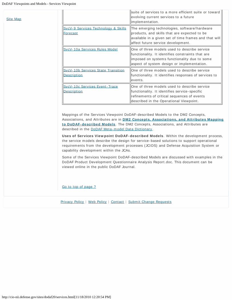
DoDAF Viewpoints and Models - Services Viewpoint
http://cio-nii.defense.gov/sites/dodaf20/services.html[11/18/2010 12:20:54 PM]
suite of services to a more efficient suite or towardevolving current services to a futureimplementation.
SvcV-9 Services Technology & SkillsForecast
The emerging technologies, software/hardwareproducts, and skills that are expected to beavailable in a given set of time frames and that willaffect future service development.
SvcV-10a Services Rules Model One of three models used to describe servicefunctionality. It identifies constraints that areimposed on systems functionality due to someaspect of system design or implementation.
SvcV-10b Services State TransitionDescription
One of three models used to describe servicefunctionality. It identifies responses of services toevents.
SvcV-10c Services Event-TraceDescription
One of three models used to describe servicefunctionality. It identifies service-specificrefinements of critical sequences of eventsdescribed in the Operational Viewpoint.
Mappings of the Services Viewpoint DoDAF-described Models to the DM2 Concepts,Associations, and Attributes are in DM2 Concepts, Associations, and Attributes Mappingto DoDAF-described Models. The DM2 Concepts, Associations, and Attributes aredescribed in the DoDAF Meta-model Data Dictionary.
Uses of Services Viewpoint DoDAF-described Models. Within the development process,the service models describe the design for service-based solutions to support operationalrequirements from the development processes (JCIDS) and Defense Acquisition System orcapability development within the JCAs.
Some of the Services Viewpoint DoDAF-described Models are discussed with examples in theDoDAF Product Development Questionnaire Analysis Report.doc. This document can beviewed online in the public DoDAF Journal.
Go to top of page ?
Site Map
Privacy Policy | Web Policy | Contact | Submit Change Requests

SvcV-1: Services Interface Description
http://cio-nii.defense.gov/sites/dodaf20/services-1.html[11/18/2010 12:32:17 PM]
Home DoDAF-DM2 WG DoDAF Journal DoD Meta Data Registry IDEAS Links
DoDAF Viewpoints and Models
Services Viewpoint
SvcV-1: Services Interface Description
The SvcV-1 addresses the composition and interaction of Services. For DoDAF V2.0, SvcV-1incorporates human elements as types of Performers - Organizations and Personnel Types.
The SvcV-1 links together the operational and services architecture models by depicting howresources are structured and interact to realize the logical architecture specified in an OV-2Operational Resource Flow Description. A SvcV-1 may represent the realization of arequirement specified in an OV-2 Operational Resource Flow Description (i.e., in a “To-Be”Architectural Description), and so there may be many alternative SvcV models that couldrealize the operational requirement. Alternatively, in an ”As-Is” Architectural Description, theOV-2 Operational Resource Flow Description may simply be a simplified, logicalrepresentation of the SvcV-1 to allow communication of key Resource Flows to non-technicalstakeholders.
It is important for the architect to recognize that the SvcV-1 focuses on the Resource Flowand the providing service. This differs from a SV-1 System Interface Description whichfocuses on the System-to-System point-to-point interface, for which the Source System andTarget System have an agreed upon interface. For the SvcV-1, the focus on the provider andthe data provided is a Net-Centric Data Strategy tenet appropriate for a publish/subscribepattern. This pattern is not the only type of service that can be captured in the SvcV-1.
Sub-services may be identified in SvcV-1 to any level (i.e., depth) of decomposition thearchitect sees fit. The SvcV-1 may also identify the Physical Assets (e.g., Platforms) at whichResources are deployed, and optionally overlay Operational Activities and Locations thatutilize those Resources. In many cases, an operational activity and locations depicted in anOV-2 Operational Resource Flow Description may well be the logical representation of theresource that is shown in SvcV-1.
The intended usage of the SvcV-1 includes:
Definition of service concepts.Definition of service options.Service Resource Flow requirements capture.Capability integration planning.Service integration management.Operational planning (capability and performer definition).
The SvcV-1 is used in two complementary ways:
Describe the Resource Flows exchanged between resources in the architecture.Describe a solution, or solution option, in terms of the components of capability andtheir physical integration on platforms and other facilities.
Detailed Description:
A SvcV-1 can be used simply to depict services and sub-services and identify the ResourceFlows between them. The real benefit of a SvcV-1 is its ability to describe the humanaspects of an architecture and how they interact with Services. In addition, DoDAF has the
Introduction
What is New in DoDAF V2.0
Vision for DoDAF V2.0
Architecture Resources
DoDAF V1.5 Support
Relationships to otherFrameworks
Background
Architecture Development
Viewpoints
All Viewpoint
Capability Viewpoint
Data and InformationViewpoint
Operational Viewpoint
Project Viewpoint
Services Viewpoint
Standards Viewpoint
Systems Viewpoint
Models
DM2
Manager Role
Architect Role
Developer Role
Department of Defense

SvcV-1: Services Interface Description
http://cio-nii.defense.gov/sites/dodaf20/services-1.html[11/18/2010 12:32:17 PM]
concept of Capability and Performers (see the Capability Meta-model group in the LDM)which is used to depict Services, assets and people into a configuration, which can meet aspecific capability. A primary purpose of a SvcV-1 model is to show resource structure, i.e.,identify the primary sub-services, performer and activities (functions) and their interactions.SvcV-1 contributes to user understanding of the structural characteristics of the solution.
The physical resources contributing to a capability are either an organizational resource or aphysical asset, i.e., a service cannot contribute alone (it must be hosted on a physical assetused by an organizational resource of both). Organizational aspects can now be shown onSvcV-1 (e.g., who uses a service). Resource structures may be identified in SvcV-1 to anylevel (i.e., depth) of decomposition the architect sees fit. DoDAF does not specifically useterms like sub-service and component as these terms often denote a position relative to astructural hierarchy. Any service may combine hardware and software or these can betreated as separate (sub) services. DoDAF V2.0 includes human factors (as Personnel Typesand a type of Performer). Should an architect wish to describe a service which has humanelements, then groupings of Services, Personnel Types and Performers should be used towrap the human and service elements together.
A SvcV-1 can optionally be annotated with Operational Activities and Locations originallyspecified in OV-2 Operational Resource Flow Description. In this way, traceability can beestablished from the logical OV structure to the physical Service Model structure.
If a single SvcV-1 is not possible, the resource of interest should be decomposed intomultiple SvcV-1 models.
Functions (Activities):
Some Resources can carry out service functions (activities) as described in SvcV-4 ServicesFunctionality Description models and these functions can optionally be overlaid on a SvcV-1.In a sense SvcV-1 and SvcV-4 Services Functionality Description provide complementaryrepresentations (structure and function). Either could be viewed first, but usually an iterativeapproach is used to model these together gradually building up the level of detail in theservice description. Note that the same type (class) of resource may be used in differentcontexts in a given SvcV-1. For this reason, the tracing of functions to resources is specifiedin context of their usage (see DM2 for details).
Resource Flows in SvcV-1:
In addition to depicting Services (Performers) and their structure, SvcV-1 addresses ServiceResource Flows. A Service Resource Flow, as depicted in SvcV-1, is an indicator thatresources pass between one service and the other. In the case of Services, this can beexpanded into further detail in SvcV-2 Services Resource Flow Description model. A ServiceResource Flow is a simplified representation of a pathway or network pattern, usuallydepicted graphically as a connector (i.e., a line with possible amplifying information). TheSvcV-1 depicts all Resource Flows between resources that are of interest. Note thatResource Flows between resources may be further specified in detail in the SvcV-2 ServicesResource Flow Description model and the SvcV-6 Services Resource Flow Matrix.
Interactions are only possible between services and systems. Service Resource Flows providea specification for how the Resource Flow exchanges specified in OV-2 Operational ResourceFlow Description Needlines are realized with services. A single Needline shown in the OV-2Operational Resource Flow Description may translate into multiple Service Resource Flows.The actual implementation of Service Resource Flows may take more than one form (e.g.,multiple physical links). Details of the physical pathways or network patterns that implementthe interfaces are documented in SvcV-2 Services Resource Flow Description. ResourceFlows are summarized in a SvcV-3a System-Service Matrix or SvcV-3b Service-ServiceMatrix and detailed definitions and attributes specific to each Service Resource Flows may bedescribed in SvcV-6 Services Resource Flow Matrix.
The functions performed by the resources are specified in a SvcV-4 Service FunctionalityDescription, but may optionally be overlaid on the Resources in a SvcV-1.
Site Map
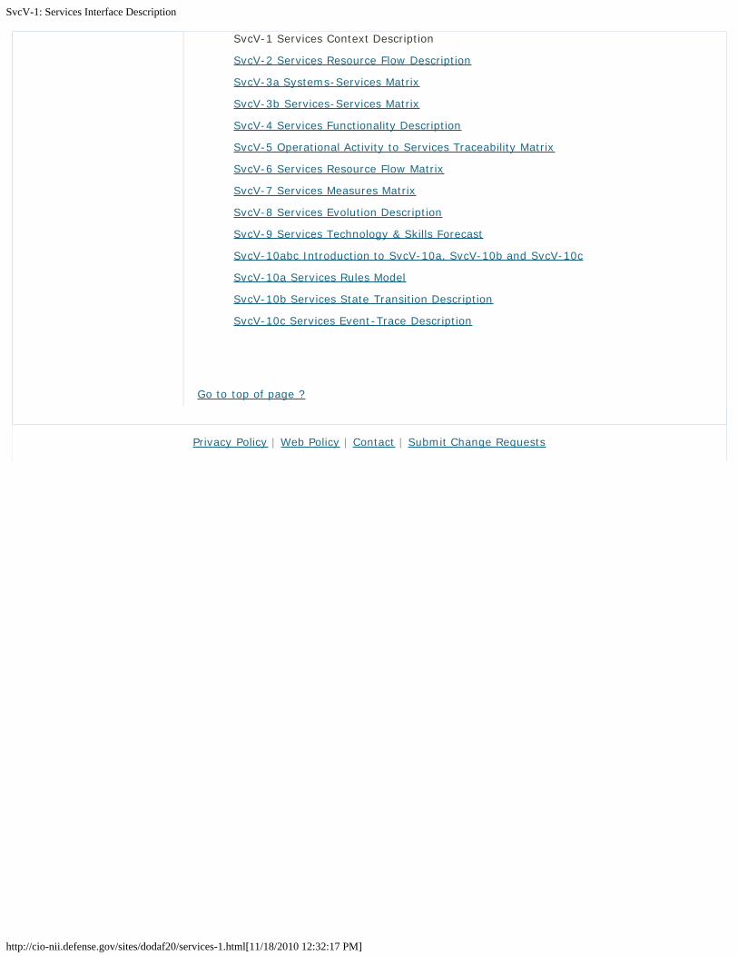
SvcV-1: Services Interface Description
http://cio-nii.defense.gov/sites/dodaf20/services-1.html[11/18/2010 12:32:17 PM]
SvcV-1 Services Context Description
SvcV-2 Services Resource Flow Description
SvcV-3a Systems-Services Matrix
SvcV-3b Services-Services Matrix
SvcV-4 Services Functionality Description
SvcV-5 Operational Activity to Services Traceability Matrix
SvcV-6 Services Resource Flow Matrix
SvcV-7 Services Measures Matrix
SvcV-8 Services Evolution Description
SvcV-9 Services Technology & Skills Forecast
SvcV-10abc Introduction to SvcV-10a, SvcV-10b and SvcV-10c
SvcV-10a Services Rules Model
SvcV-10b Services State Transition Description
SvcV-10c Services Event-Trace Description
Go to top of page ?
Privacy Policy | Web Policy | Contact | Submit Change Requests

SvcV-2: Services Resource Flow Description
http://cio-nii.defense.gov/sites/dodaf20/services-2.html[11/18/2010 12:32:26 PM]
Home DoDAF-DM2 WG DoDAF Journal DoD Meta Data Registry IDEAS Links
DoDAF Viewpoints and Models
Services Viewpoint
SvcV-2: Services Resource Flow Description
A SvcV-2 specifies the Resource Flows between Services and may also list the protocolstacks used in connections.
A SvcV-2 DoDAF-described Model is used to give a precise specification of a connectionbetween Services. This may be an existing connection or a specification of a connection thatis to be made for a future connection.
The intended usage of the SvcV-2 includes:
Resource Flow specification.
Detailed Description:
For a network data service, a SvcV-2 comprises Services, their ports, and the ServiceResource Flows between those ports. The SvcV-2 may also be used to describe non-IT typeservices such as Search and Rescue. The architect may choose to create a diagram for eachService Resource Flow and the producing Service, each Service Resource Flow andconsuming Service, or to show all the Service Resource Flows on one diagram, if this ispossible.
Each SvcV-2 model can show:
Which ports are connected.The producing Services that the ports belong to.The Services that the Service Resource Flows are consumed by.The definition of the Service Resource Flow in terms of the physical/logicalconnectivity and any protocols that are used in the connection.
Note that networks are represented as Services. The architect may choose to show otherServices being components of the network, i.e., if they are part of the networkinfrastructure.
Any protocol referred to in a SvcV-2 diagram needs be defined in the StdV-1 StandardsProfile.
SvcV-1 Services Context Description
SvcV-2 Services Resource Flow Description
SvcV-3a Systems-Services Matrix
SvcV-3b Services-Services Matrix
SvcV-4 Services Functionality Description
SvcV-5 Operational Activity to Services Traceability Matrix
SvcV-6 Services Resource Flow Matrix
SvcV-7 Services Measures Matrix
SvcV-8 Services Evolution Description
Introduction
What is New in DoDAF V2.0
Vision for DoDAF V2.0
Architecture Resources
DoDAF V1.5 Support
Relationships to otherFrameworks
Background
Architecture Development
Viewpoints
All Viewpoint
Capability Viewpoint
Data and InformationViewpoint
Operational Viewpoint
Project Viewpoint
Services Viewpoint
Standards Viewpoint
Systems Viewpoint
Models
DM2
Manager Role
Architect Role
Developer Role
Department of Defense

SvcV-2: Services Resource Flow Description
http://cio-nii.defense.gov/sites/dodaf20/services-2.html[11/18/2010 12:32:26 PM]
SvcV-9 Services Technology & Skills Forecast
SvcV-10abc Introduction to SvcV-10a, SvcV-10b and SvcV-10c
SvcV-10a Services Rules Model
SvcV-10b Services State Transition Description
SvcV-10c Services Event-Trace Description
Go to top of page ?
Site Map
Privacy Policy | Web Policy | Contact | Submit Change Requests

SvcV-3a: Systems-Services Matrix
http://cio-nii.defense.gov/sites/dodaf20/services-3a.html[11/18/2010 12:32:35 PM]
Home DoDAF-DM2 WG DoDAF Journal DoD Meta Data Registry IDEAS Links
DoDAF Viewpoints and Models
Services Viewpoint
SvcV-3a: Systems-Services Matrix
A SvcV-3a enables a quick overview of all the system-to-service resource interactionsspecified in one or more SvcV-1 Services Context Description models. The SvcV-3a providesa tabular summary of the system and services interactions specified in the SvcV-1 ServicesContext Description for the Architectural Description. This model can be useful in supportexisting systems that are transitioning to provide services. The matrix format supports arapid assessment of potential commonalities and redundancies (or, if fault-tolerance isdesired, the lack of redundancies).
The SvcV-3a can be organized in a number of ways to emphasize the association of system-to-service interactions in context with the architecture’s purpose.
The intended usage of the SvcV-3a includes:
Summarizing system and service resource interactions.Interface management.Comparing interoperability characteristics of solution options.
Detailed Description:
The SvcV-1 concentrates on Service resources and their interactions, and these aresummarized in a SvcV-3a or SvcV-3b. The SvcV-3a DoDAF-described Model can be a usefultool for managing the evolution of solutions and infrastructures, the insertion of newtechnologies and functionality, and the redistribution of Systems and Services and activitiesin context with evolving operational requirements.
Depending upon the purpose of the architecture, there could be several SvcV-3a DoDAF-described Models. The suite of SvcV-3a models can be organized in a number of ways (e.g.,by domain, by operational mission phase, by solution option) to emphasize the association ofgroups of resource pairs in context with the Architectural Description’s purpose.
The SvcV-3a is generally presented as a matrix, where the System and Services resourcesare listed in the rows and columns of the matrix, and each cell indicates an interactionbetween Systems and Services if one exists. Many types of interaction information can bepresented in the cells of a SvcV-3a. The resource interactions can be represented usingdifferent symbols and/or color coding that depicts different interaction characteristics, forexample:
Status (e.g., existing, planned, potential, de-activated).Key interfaces.Category (e.g., command and control, intelligence, personnel, logistics).Classification-level (e.g., Restricted, Confidential, Secret, Top Secret).Communication means (e.g., Rim Loop Interface, Scalable Loop Interface).
DoDAF does not specify the symbols to be used. If symbols are used, a key for the symbolsis needed.
SvcV-1 Services Context Description
Introduction
What is New in DoDAF V2.0
Vision for DoDAF V2.0
Architecture Resources
DoDAF V1.5 Support
Relationships to otherFrameworks
Background
Architecture Development
Viewpoints
All Viewpoint
Capability Viewpoint
Data and InformationViewpoint
Operational Viewpoint
Project Viewpoint
Services Viewpoint
Standards Viewpoint
Systems Viewpoint
Models
DM2
Manager Role
Architect Role
Developer Role
Department of Defense

SvcV-3a: Systems-Services Matrix
http://cio-nii.defense.gov/sites/dodaf20/services-3a.html[11/18/2010 12:32:35 PM]
SvcV-2 Services Resource Flow Description
SvcV-3a Systems-Services Matrix
SvcV-3b Services-Services Matrix
SvcV-4 Services Functionality Description
SvcV-5 Operational Activity to Services Traceability Matrix
SvcV-6 Services Resource Flow Matrix
SvcV-7 Services Measures Matrix
SvcV-8 Services Evolution Description
SvcV-9 Services Technology & Skills Forecast
SvcV-10abc Introduction to SvcV-10a, SvcV-10b and SvcV-10c
SvcV-10a Services Rules Model
SvcV-10b Services State Transition Description
SvcV-10c Services Event-Trace Description
Go to top of page ?
Site Map
Privacy Policy | Web Policy | Contact | Submit Change Requests

SvcV-3b: Services-Services Matrix
http://cio-nii.defense.gov/sites/dodaf20/services-3b.html[11/18/2010 12:32:44 PM]
Home DoDAF-DM2 WG DoDAF Journal DoD Meta Data Registry IDEAS Links
DoDAF Viewpoints and Models
Services Viewpoint
SvcV-3b: Services-Services Matrix
A SvcV-3b enables a quick overview of all the services resource interactions specified in oneor more SvcV-1 Services Context Description models. The SvcV-3b provides a tabularsummary of the services interactions specified in the SvcV-1 Services Context Description forthe Architectural Description. The matrix format supports a rapid assessment of potentialcommonalities and redundancies (or, if fault-tolerance is desired, the lack of redundancies).In addition, this model is useful in support of net-centric (service-oriented) implementationof services as an input to the SvcV-10a Services Rules Model, SvcV-10b Services StateTransition Description, and SvcV-10c Services Event-Trace Description, implemented asorchestrations of services.
The SvcV-3b can be organized in a number of ways to emphasize the association of servicepairs in context with the architecture’s purpose. One type of organization is a ServiceHierarchy or Taxonomy of Services.
The intended usage of the SvcV-3b includes:
Summarizing service resource interactions.Interface management.Comparing interoperability characteristics of solution options.
It is important to note that one usage of the Service-Service Matrix (SvcV-3b) can support anet- centric (service-oriented) implementation in describing the interactions betweenproducing services and consuming services.
Detailed Description:
The SvcV-1 concentrates on Service resources and their interactions, and these aresummarized in a SvcV-3a or SvcV-3b. The SvcV-3b can be a useful tool for managing theevolution of solutions and infrastructures, the insertion of new technologies and functionality,and the redistribution of Services and activities in context with evolving operationalrequirements.
Depending upon the purpose of the architecture, there could be several SvcV-3b DoDAF-described Models. The suite of SvcV-3b DoDAF-described Models can be organized in anumber of ways (e.g., by domain, by operational mission phase, by solution option) toemphasize the association of groups of resource pairs in context with the ArchitecturalDescription purpose.
The SvcV-3b is generally presented as a matrix, where the Services resources are listed inthe rows and columns of the matrix, and each cell indicates an interaction between Servicesif one exists. There are many types of information that can be presented in the cells of aSvcV-3b. The resource interactions can be represented using different symbols and/or colorcoding that depicts different interaction characteristics, for example:
Status (e.g., existing, planned, potential, de-activated).Key interfaces.Category (e.g., command and control, intelligence, personnel, logistics).Classification-level (e.g., Restricted, Confidential, Secret, Top Secret).
Introduction
What is New in DoDAF V2.0
Vision for DoDAF V2.0
Architecture Resources
DoDAF V1.5 Support
Relationships to otherFrameworks
Background
Architecture Development
Viewpoints
All Viewpoint
Capability Viewpoint
Data and InformationViewpoint
Operational Viewpoint
Project Viewpoint
Services Viewpoint
Standards Viewpoint
Systems Viewpoint
Models
DM2
Manager Role
Architect Role
Developer Role
Department of Defense

SvcV-3b: Services-Services Matrix
http://cio-nii.defense.gov/sites/dodaf20/services-3b.html[11/18/2010 12:32:44 PM]
Communication means (e.g., Rim Loop Interface, Scalable Loop Interface).
DoDAF does not specify the symbols to be used. If symbols are used, a key for the symbolsis needed.
SvcV-1 Services Context Description
SvcV-2 Services Resource Flow Description
SvcV-3a Systems-Services Matrix
SvcV-3b Services-Services Matrix
SvcV-4 Services Functionality Description
SvcV-5 Operational Activity to Services Traceability Matrix
SvcV-6 Services Resource Flow Matrix
SvcV-7 Services Measures Matrix
SvcV-8 Services Evolution Description
SvcV-9 Services Technology & Skills Forecast
SvcV-10abc Introduction to SvcV-10a, SvcV-10b and SvcV-10c
SvcV-10a Services Rules Model
SvcV-10b Services State Transition Description
SvcV-10c Services Event-Trace Description
Go to top of page ?
Site Map
Privacy Policy | Web Policy | Contact | Submit Change Requests

SvcV-4: Services Functionality Description
http://cio-nii.defense.gov/sites/dodaf20/services-4.html[11/18/2010 12:32:52 PM]
Home DoDAF-DM2 WG DoDAF Journal DoD Meta Data Registry IDEAS Links
DoDAF Viewpoints and Models
Services Viewpoint
SvcV-4: Services Functionality Description
The SvcV-4 DoDAF-described Model addresses human and service functionality.
The primary purpose of SvcV-4 is to:
Develop a clear description of the necessary data flows that are input (consumed) byand output (produced) by each resource.Ensure that the service functional connectivity is complete (i.e., that a resource’srequired inputs are all satisfied).Ensure that the functional decomposition reaches an appropriate level of detail.
The Services Functionality Description provides detailed information regarding the:
Allocation of service functions to resources.Flow of resources between service functions.
The SvcV-4 is the Services Viewpoint counterpart to the OV-5b Operational Activity Model ofthe Operational Viewpoint.
The intended usage of the SvcV-4 includes:
Description of task workflow.Identification of functional service requirements.Functional decomposition of Services.Relate human and service functions.
It is important to note that one usage of the SvcV-4 can support a net-centric (service-oriented) implementation in describing the producing services and consuming services. TheServices Functionality Description information can support the registration of services in net-centric (service-oriented) implementation.
Detailed Description:
The SvcV-4 is used to specify the service functionality of resources in the architecture. TheSvcV-4 is the behavioral counterpart to the SvcV-1 Services Context Description (in thesame way that OV-5b Operational Activity Model is the behavioral counterpart to OV-2Operational Resource Flow Description).
The scope of this model may be capability wide, without regard to which resources performwhich service functions, or it may be resource-specific. Variations may focus on intra- orinter-resource data flows, or may simply allocate service functions to resources.
There are two basic ways to depict a SvcV-4:
The Taxonomic Service Functional Hierarchy shows a decomposition of servicefunctions depicted in a tree structure and is typically used where tasks are concurrentbut dependent, such as a production line, for example.The Data Flow Diagram shows service functions connected by data flow arrows anddata stores.
Introduction
What is New in DoDAF V2.0
Vision for DoDAF V2.0
Architecture Resources
DoDAF V1.5 Support
Relationships to otherFrameworks
Background
Architecture Development
Viewpoints
All Viewpoint
Capability Viewpoint
Data and InformationViewpoint
Operational Viewpoint
Project Viewpoint
Services Viewpoint
Standards Viewpoint
Systems Viewpoint
Models
DM2
Manager Role
Architect Role
Developer Role
Department of Defense

SvcV-4: Services Functionality Description
http://cio-nii.defense.gov/sites/dodaf20/services-4.html[11/18/2010 12:32:52 PM]
Within an Architectural Description, the SvcV-4 document service functions, the ResourceFlows between those service functions, the internal system data repositories or service datastores, and the external sources and sinks for the service data flows, but not external to theArchitectural Description’s scope. They may also show how users behave in relation to thoseservices.
SvcV-1 Services Context Description
SvcV-2 Services Resource Flow Description
SvcV-3a Systems-Services Matrix
SvcV-3b Services-Services Matrix
SvcV-4 Services Functionality Description
SvcV-5 Operational Activity to Services Traceability Matrix
SvcV-6 Services Resource Flow Matrix
SvcV-7 Services Measures Matrix
SvcV-8 Services Evolution Description
SvcV-9 Services Technology & Skills Forecast
SvcV-10abc Introduction to SvcV-10a, SvcV-10b and SvcV-10c
SvcV-10a Services Rules Model
SvcV-10b Services State Transition Description
SvcV-10c Services Event-Trace Description
Go to top of page ?
Site Map
Privacy Policy | Web Policy | Contact | Submit Change Requests

SvcV-5: Operational Activity to Services Traceability Matrix
http://cio-nii.defense.gov/sites/dodaf20/services-5.html[11/18/2010 12:33:04 PM]
Home DoDAF-DM2 WG DoDAF Journal DoD Meta Data Registry IDEAS Links
DoDAF Viewpoints and Models
Services Viewpoint
SvcV-5: Operational Activity to Services Traceability Matrix
The SvcV-5 addresses the linkage between service functions described in SvcV-4 andOperational Activities specified in OV-5a Operational Activity Decomposition Tree or OV-5bOperational Activity Model. The SvcV-5 depicts the mapping of service functions (and,optionally, the capabilities and performers that provide them) to operational activities andthus identifies the transformation of an operational need into a purposeful action performedby a service solution.
During requirements definition, the SvcV-5 plays a particularly important role in tracing thearchitectural elements associated with system function requirements to those associatedwith user requirements.
The intended usage of the SvcV-5 includes:
Tracing service functional requirements to user requirements.Tracing solution options to requirements.Identification of overlaps or gaps.
Detailed Description:
An SvcV-5 is a specification of the relationships between the set of operational activitiesapplicable to an Architectural Description and the set of service functions applicable to thatArchitectural Description. The relationship between operational activities and servicefunctions can also be expected to be many-to-many (i.e., one activity may be supported bymultiple functions, and one function may support multiple activities). The service functionsshown in the SvcV-5 may be those associated with capabilities and performers. More focusedSvcV-5 models might be used to specifically trace system functions to operational activitiesif desired.
DoDAF uses the term Operational Activity in the OVs and the term Service Function in theSVs to refer to essentially the same kind of thing—both activities and service functions aretasks that are performed, accept inputs, and develop outputs. The distinction between anOperational Activity and a Service Function is a question of what and how. The OperationalActivity is a specification of what is to be done, regardless of the mechanism used. A ServiceFunction specifies how a resource carries it out. For this reason, the SvcV-5 is a significantmodel, as it ties together the logical specification in the OV-5a Operational ActivityDecomposition Tree or OV-5b Operational Activity Model with the physical specification of theSvcV-4 Services Functionality Description. Service Functions can be carried out byResources.
Care should be taken when publishing a SvcV-5 with status information. Any presentationshould clearly state the date of publication, so that users can see when status information isold.
The SvcV-5 may be further annotated with Services, Capabilities, Performers executingActivities, and capabilities and performers that conduct the functions.
The SvcV-5 is generally presented as a matrix of the relationship between service functionsand activities. The SvcV-5 can show requirements traceability with Operational Activities on
Introduction
What is New in DoDAF V2.0
Vision for DoDAF V2.0
Architecture Resources
DoDAF V1.5 Support
Relationships to otherFrameworks
Background
Architecture Development
Viewpoints
All Viewpoint
Capability Viewpoint
Data and InformationViewpoint
Operational Viewpoint
Project Viewpoint
Services Viewpoint
Standards Viewpoint
Systems Viewpoint
Models
DM2
Manager Role
Architect Role
Developer Role
Department of Defense

SvcV-5: Operational Activity to Services Traceability Matrix
http://cio-nii.defense.gov/sites/dodaf20/services-5.html[11/18/2010 12:33:04 PM]
one axis of a matrix, the System Functions on the other axis, and with an X, date, or phasein the intersecting cells, where appropriate.
An alternate version of the tabular SvcV-5 can allow the implementation status of eachfunction to be shown. In this variant model, each service function-to-operational activitymapping is described by a traffic light symbol that may indicate the status of the servicesupport. DoDAF V2.0 does not prescribe a presentation technique. These symbols are usuallycolored circles with the following possible representations:
Red may indicate that the functionality is planned but not developed.Yellow may indicate that partial functionality has been provided (or full functionalityprovided but system has not been fielded).Green may indicate that full functionality has been provided to the field.A blank cell may indicate that there is no service support planned for an OperationalActivity, or that a relationship does not exist between the Operational Activity and theService Function.
SvcV-1 Services Context Description
SvcV-2 Services Resource Flow Description
SvcV-3a Systems-Services Matrix
SvcV-3b Services-Services Matrix
SvcV-4 Services Functionality Description
SvcV-5 Operational Activity to Services Traceability Matrix
SvcV-6 Services Resource Flow Matrix
SvcV-7 Services Measures Matrix
SvcV-8 Services Evolution Description
SvcV-9 Services Technology & Skills Forecast
SvcV-10abc Introduction to SvcV-10a, SvcV-10b and SvcV-10c
SvcV-10a Services Rules Model
SvcV-10b Services State Transition Description
SvcV-10c Services Event-Trace Description
Go to top of page ?
Site Map
Privacy Policy | Web Policy | Contact | Submit Change Requests

SvcV-6: Services Resource Flow Matrix
http://cio-nii.defense.gov/sites/dodaf20/services-6.html[11/18/2010 12:33:15 PM]
Home DoDAF-DM2 WG DoDAF Journal DoD Meta Data Registry IDEAS Links
DoDAF Viewpoints and Models
Services Viewpoint
SvcV-6: Services Resource Flow Matrix
The SvcV-6 specifies the characteristics of the Service Resource Flows exchanged betweenServices. The focus is on resource crossing the service boundary. The SvcV-6 focuses on thespecific aspects of the Service Resource Flow and the Service Resource Flow content in atabular format.
In addition, this model is useful in support of net-centric (service-oriented) implementationof services. According to the Net-Centric Data Strategy, a net-centric implementation needsto focus in on the data in the Service Resource Flow, as well as the services that produce orconsume the data of the Service Resource Flow. In a net-centric implementation, not all theconsumers are known and this model emphasizes the focus on the producer and ServiceResource Flow.
The intended usage of the SvcV-6 includes:
• Detailed definition of Resource Flows.
Detailed Description:
The SvcV-6 specifies the characteristics of Service Resource Flow exchanges betweenServices. The SvcV- is the physical equivalent of the logical OV-3 Operational Resource FlowMatrix and provides detailed information on the service connections which implement theResource Flow exchanges specified in OV-3 Operational Resource Flow Matrix. Resource flowexchange solutions, whether automated or not, e.g., such as verbal orders, are alsocaptured.
Service Resource Flow exchanges express the relationship across the three basicarchitectural data elements of a SvcV (Services, service functions, and Service ResourceFlows) and focus on the specific aspects of the Service Resource Flow and the serviceresource content. These aspects of the service Resource Flow exchange can be crucial to theoperational mission and are critical to understanding the potential for overhead andconstraints introduced by the physical aspects of the implementation such as security policyand communications and logistics limitations.
The focus of SvcV-6 is on how the Service Resource Flow exchange is affected, in service-specific details covering periodicity, timeliness, throughput, size, information assurance, andsecurity characteristics of the resource exchange. In addition, for Service Resource Flow ofdata, their format and media type, accuracy, units of measurement, applicable system datastandards, and any DIV-3 Physical Data Models are also described or referenced in thematrix.
Modeling discipline is needed to ensure that the architecture models are coherent. EachService Resource Flow exchange listed in the SvcV-6 table should be traceable to at leastone Operational Resource Flow exchanged listed in the corresponding OV-3 OperationalResource Flow Matrix and these in turn trace to OV-2 Operational Resource Flow Description.
It should be noted that each resource exchanged may relate to a known service function(from SvcV-4) that produces or consumes it. However, there need not be a one-to-onecorrelation between data elements listed in the SvcV-6 matrix and the Resource Flows(inputs and outputs) that are produced or consumed in a related SvcV-4 because the SvcV-4
Introduction
What is New in DoDAF V2.0
Vision for DoDAF V2.0
Architecture Resources
DoDAF V1.5 Support
Relationships to otherFrameworks
Background
Architecture Development
Viewpoints
All Viewpoint
Capability Viewpoint
Data and InformationViewpoint
Operational Viewpoint
Project Viewpoint
Services Viewpoint
Standards Viewpoint
Systems Viewpoint
Models
DM2
Manager Role
Architect Role
Developer Role
Department of Defense
SvcV-6: Services Resource Flow Matrix
http://cio-nii.defense.gov/sites/dodaf20/services-6.html[11/18/2010 12:33:15 PM]
is more a logical solution, whereas the SvcV-6 is a more physical solution. In addition,Resource flows between known service functions performed by the same Services may notbe shown in the SvcV-6 matrix. The SvcV-6 is about showing flows across serviceboundaries or a service boundary. If the Resource Flow is information, it may need to bereflected in the Data and Information Models.
The SvcV-7 Services Measures Matrix builds on the SvcV-6 and should be developed at thesame time.
DoDAF does not prescribe the column headings in a SvcV-6 Matrix. Identifiers of theoperational Resource Flow exchanges (OV-3) that are implemented by the Service ResourceFlow Exchanges may be included in the table. All elements carried by the Resource Flowexchanges may be shown.
SvcV-1 Services Context Description
SvcV-2 Services Resource Flow Description
SvcV-3a Systems-Services Matrix
SvcV-3b Services-Services Matrix
SvcV-4 Services Functionality Description
SvcV-5 Operational Activity to Services Traceability Matrix
SvcV-6 Services Resource Flow Matrix
SvcV-7 Services Measures Matrix
SvcV-8 Services Evolution Description
SvcV-9 Services Technology & Skills Forecast
SvcV-10abc Introduction to SvcV-10a, SvcV-10b and SvcV-10c
SvcV-10a Services Rules Model
SvcV-10b Services State Transition Description
SvcV-10c Services Event-Trace Description
Go to top of page ?
Site Map
Privacy Policy | Web Policy | Contact | Submit Change Requests

SvcV-7: Services Measures Matrix
http://cio-nii.defense.gov/sites/dodaf20/services-7.html[11/18/2010 12:33:24 PM]
Home DoDAF-DM2 WG DoDAF Journal DoD Meta Data Registry IDEAS Links
DoDAF Viewpoints and Models
Services Viewpoint
SvcV-7: Services Measures Matrix
The SvcV-7 depicts the measures (metrics) of resources. The Services Measures Matrixexpands on the information presented in a SvcV-1 Services Context Description by depictingthe characteristics of the resources in the SvcV-1 Services Context Description.
In addition, this model is useful in support of net-centric (service-oriented) implementationof services. Service measures for Service Level Agreements for each service and may includenumber of service consumers, service usage by consumers, and the minimum, average andmaximum response times, allowed down time, etc. Measures of interest for a ChiefInformation Office or Program manager may include measures that assess service reuse,process efficiency, and business agility.
The intended usage of the SvcV-7 includes:
Definition of performance characteristics and measures (metrics).Identification of non-functional requirements.
Detailed Description:
The SvcV-7 specifies qualitative and quantitative measures (metrics) of resources. Itspecifies all of the measures. The measures are selected by the end user community anddescribed by the architect.
Performance parameters include all performance characteristics for which requirements canbe developed and specifications defined. The complete set of performance parameters maynot be known at the early stages of Architectural Description, so it is to be expected that thismodel is updated throughout the specification, design, development, testing, and possiblyeven its deployment and operations lifecycle phases. The performance characteristics arecaptured in the Measures Meta-model group.
One of the primary purposes of SvcV-7 is to communicate which measures are consideredmost crucial for the successful achievement of the mission goals assigned. These particularmeasures can often be the deciding factors in acquisition and deployment decisions, andfigure strongly in services analysis and simulations done to support the acquisition decisionprocesses and system design refinement and be input or may impact decisions about ServiceLevel Agreement content. Measures of Effectiveness (MOEs) and Measures of Performers(MOPs) are measures that can be captured and presented in the Services Measures Matrixmodel.
SvcV-7 is typically a table, listing user defined measures (metrics) with a time periodassociation. It is sometimes useful to analyze evolution by comparing measures (metrics) forcurrent and future resources. For this reason, a hybrid SvcV-7 Model which spansarchitectures across multiple phases may be useful.
SvcV-1 Services Context Description
SvcV-2 Services Resource Flow Description
SvcV-3a Systems-Services Matrix
Introduction
What is New in DoDAF V2.0
Vision for DoDAF V2.0
Architecture Resources
DoDAF V1.5 Support
Relationships to otherFrameworks
Background
Architecture Development
Viewpoints
All Viewpoint
Capability Viewpoint
Data and InformationViewpoint
Operational Viewpoint
Project Viewpoint
Services Viewpoint
Standards Viewpoint
Systems Viewpoint
Models
DM2
Manager Role
Architect Role
Developer Role
Department of Defense

SvcV-7: Services Measures Matrix
http://cio-nii.defense.gov/sites/dodaf20/services-7.html[11/18/2010 12:33:24 PM]
SvcV-3b Services-Services Matrix
SvcV-4 Services Functionality Description
SvcV-5 Operational Activity to Services Traceability Matrix
SvcV-6 Services Resource Flow Matrix
SvcV-7 Services Measures Matrix
SvcV-8 Services Evolution Description
SvcV-9 Services Technology & Skills Forecast
SvcV-10abc Introduction to SvcV-10a, SvcV-10b and SvcV-10c
SvcV-10a Services Rules Model
SvcV-10b Services State Transition Description
SvcV-10c Services Event-Trace Description
Go to top of page ?
Site Map
Privacy Policy | Web Policy | Contact | Submit Change Requests

SvcV-8: Services Evolution Description
http://cio-nii.defense.gov/sites/dodaf20/services-8.html[11/18/2010 12:34:53 PM]
Home DoDAF-DM2 WG DoDAF Journal DoD Meta Data Registry IDEAS Links
DoDAF Viewpoints and Models
Services Viewpoint
SvcV-8: Services Evolution Description
The SvcV-8 presents a whole lifecycle view of resources (services), describing how itchanges over time. It shows the structure of several resources mapped against a timeline.
In addition, this model is useful in support of net-centric (service-oriented) implementationof services. This model can present a timeline of services evolve or are replaced over time,including services that are internal and external to the scope of the architecture.
The intended usage of the SvcV-8 includes:
Development of incremental acquisition strategy.Planning technology insertion.
Detailed Description:
The SvcV-8, when linked together with other evolution Models such as CV-2 CapabilityTaxonomy, CV-3 Capability Phasing and StdV-2 Standards Forecast, provides a richdefinition of how the Enterprise and its capabilities are expected to evolve over time. In thismanner, the model can be used to support an architecture evolution project plan ortransition plan.
A SvcV-8 can describe historical (legacy), current, and future capabilities against a timeline.The model shows the structure of each resource, using similar modeling elements as thoseused in SvcV-1. Interactions which take place within the resource may also be shown.
The changes depicted in the SvcV-8 DoDAF-described Model are derived from the projectmilestones that are shown in a PV-2 Project Timelines model. When the PV-2 ProjectTimelines model is used for capability acquisition projects, there is likely to be a closerelationship between these two models.
SvcV-1 Services Context Description
SvcV-2 Services Resource Flow Description
SvcV-3a Systems-Services Matrix
SvcV-3b Services-Services Matrix
SvcV-4 Services Functionality Description
SvcV-5 Operational Activity to Services Traceability Matrix
SvcV-6 Services Resource Flow Matrix
SvcV-7 Services Measures Matrix
SvcV-8 Services Evolution Description
SvcV-9 Services Technology & Skills Forecast
SvcV-10abc Introduction to SvcV-10a, SvcV-10b and SvcV-10c
SvcV-10a Services Rules Model
SvcV-10b Services State Transition Description
Introduction
What is New in DoDAF V2.0
Vision for DoDAF V2.0
Architecture Resources
DoDAF V1.5 Support
Relationships to otherFrameworks
Background
Architecture Development
Viewpoints
All Viewpoint
Capability Viewpoint
Data and InformationViewpoint
Operational Viewpoint
Project Viewpoint
Services Viewpoint
Standards Viewpoint
Systems Viewpoint
Models
DM2
Manager Role
Architect Role
Developer Role
Department of Defense

SvcV-8: Services Evolution Description
http://cio-nii.defense.gov/sites/dodaf20/services-8.html[11/18/2010 12:34:53 PM]
SvcV-10c Services Event-Trace Description
Go to top of page ?
Site Map
Privacy Policy | Web Policy | Contact | Submit Change Requests

SvcV-9: Services Technology and Skills Forecast
http://cio-nii.defense.gov/sites/dodaf20/services-9.html[11/18/2010 12:35:04 PM]
Home DoDAF-DM2 WG DoDAF Journal DoD Meta Data Registry IDEAS Links
DoDAF Viewpoints and Models
Services Viewpoint
SvcV-9: Services Technology and Skills Forecast
The SvcV-9 defines the underlying current and expected supporting technologies and skills.Expected supporting technologies and skills are those that can be reasonably forecast giventhe current state of technology and skills, and expected improvements or trends. Newtechnologies and skills are tied to specific time periods, which can correlate against the timeperiods used in SvcV-8 Services Evolution Description model milestones and linked toCapability Phases.
The SvcV-9 provides a summary of emerging technologies and skills that impact thearchitecture. The SvcV-9 provides descriptions of relevant:
Emerging capabilities.Industry trends.Predictions (with associated confidence factors) of the availability and readiness ofspecific hardware and software services.Current and possible future skills.
In addition to providing an inventory of trends, capabilities and services, the SvcV-9 alsoincludes an assessment of the potential impact of these items on the architecture. Given thefuture-oriented nature of this model, forecasts are typically made in short, mid and long-term timeframes, such as 6, 12 and 18-month intervals.
In addition, this model is useful in support of net-centric (service-oriented) implementationof services. As technologies change, like incorporation of Representational State Transfer(REST) services in the Web Services Description Language, this model can present a timelineof technologies related services over time.
The intended usage of the SvcV-9 includes:
Forecasting technology readiness against time.HR Trends Analysis.Recruitment Planning.Planning technology insertion.Input to options analysis.
The SvcV-9 can be presented in a table, timeline, or a Herringbone diagram.
Detailed Description:
A SvcV-9 summarizes predictions about trends in technology and personnel. Architects mayproduce separate SvcV-9 products for technology and human resources. The specific timeperiods selected (and the trends being tracked) can be coordinated with architecturetransition plans (which the SvcV-8 Services Evolution Description can support). That is,insertion of new capabilities and upgrading or re-training of existing resources may dependon or be driven by the availability of new technology and associated skills. The forecastincludes potential impacts on current architectures and thus influences the development oftransition and target architectures. The forecast is focused on technology and humanresource areas that are related to the purpose for which a given architecture is being
Introduction
What is New in DoDAF V2.0
Vision for DoDAF V2.0
Architecture Resources
DoDAF V1.5 Support
Relationships to otherFrameworks
Background
Architecture Development
Viewpoints
All Viewpoint
Capability Viewpoint
Data and InformationViewpoint
Operational Viewpoint
Project Viewpoint
Services Viewpoint
Standards Viewpoint
Systems Viewpoint
Models
DM2
Manager Role
Architect Role
Developer Role
Department of Defense

SvcV-9: Services Technology and Skills Forecast
http://cio-nii.defense.gov/sites/dodaf20/services-9.html[11/18/2010 12:35:04 PM]
described and identifies issues affecting that architecture.
If standards are an integral part of the technologies important to the evolution of a givenarchitecture, then it may be convenient to combine SvcV-9 with the StdV-2 StandardsForecast into a composite Fit-for-Purpose View.
The SvcV-9 is constructed as part of a given Architectural Description and in accordance withthe its purpose. Typically, this involves starting with one or more overarching referencemodels or standards profiles to which the architecture is subject to using. Using thesereference models or standards profiles, the architect selects the service areas and servicesrelevant to the architecture. The SvcV-9 forecasts relate to the StdV-1Standards Profile inthat a timed forecast may contribute to the decision to retire or phase out the use of acertain standard in connection with a resource. Similarly, the SvcV-9 forecasts relate to theStdV-2 Standards Forecasts in that a certain standard may be adopted depending on acertain technology or skill becoming available (e.g., the availability of Java Script mayinfluence the decision to adopt a new HTML standard).
Alternatively, the SvcV-9 may relate forecasts to Service Model elements (e.g., Services)where applicable. The list of resources potentially impacted by the forecasts can also besummarized as additional information in SvcV-9.
SvcV-1 Services Context Description
SvcV-2 Services Resource Flow Description
SvcV-3a Systems-Services Matrix
SvcV-3b Services-Services Matrix
SvcV-4 Services Functionality Description
SvcV-5 Operational Activity to Services Traceability Matrix
SvcV-6 Services Resource Flow Matrix
SvcV-7 Services Measures Matrix
SvcV-8 Services Evolution Description
SvcV-9 Services Technology & Skills Forecast
SvcV-10abc Introduction to SvcV-10a, SvcV-10b and SvcV-10c
SvcV-10a Services Rules Model
SvcV-10b Services State Transition Description
SvcV-10c Services Event-Trace Description
Go to top of page ?
Site Map
Privacy Policy | Web Policy | Contact | Submit Change Requests
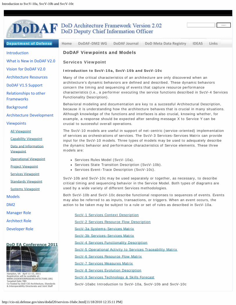
Introduction to SvcV-10a, SvcV-10b and SvcV-10c
http://cio-nii.defense.gov/sites/dodaf20/services-10abc.html[11/18/2010 12:35:11 PM]
Home DoDAF-DM2 WG DoDAF Journal DoD Meta Data Registry IDEAS Links
DoDAF Viewpoints and Models
Services Viewpoint
Introduction to SvcV-10a, SvcV-10b and SvcV-10c
Many of the critical characteristics of an architecture are only discovered when anarchitecture’s dynamic behaviors are defined and described. These dynamic behaviorsconcern the timing and sequencing of events that capture resource performancecharacteristics (i.e., a performer executing the service functions described in SvcV-4 ServicesFunctionality Description).
Behavioral modeling and documentation are key to a successful Architectural Description,because it is understanding how the architecture behaves that is crucial in many situations.Although knowledge of the functions and interfaces is also crucial, knowing whether, forexample, a response should be expected after sending message X to Service Y can becrucial to successful overall operations.
The SvcV-10 models are useful in support of net-centric (service-oriented) implementationof services as orchestrations of services. The SvcV-3 Services-Services Matrix can provideinput for the SvcV-10 models. Three types of models may be used to adequately describethe dynamic behavior and performance characteristics of Service elements. These threemodels are:
Services Rules Model (SvcV-10a).Services State Transition Description (SvcV-10b).Services Event-Trace Description (SvcV-10c).
SvcV-10b and SvcV-10c may be used separately or together, as necessary, to describecritical timing and sequencing behavior in the Service Model. Both types of diagrams areused by a wide variety of different Services methodologies.
Both SvcV-10b and SvcV-10c describe functional responses to sequences of events. Eventsmay also be referred to as inputs, transactions, or triggers. When an event occurs, theaction to be taken may be subject to a rule or set of rules as described in SvcV-10a.
SvcV-1 Services Context Description
SvcV-2 Services Resource Flow Description
SvcV-3a Systems-Services Matrix
SvcV-3b Services-Services Matrix
SvcV-4 Services Functionality Description
SvcV-5 Operational Activity to Services Traceability Matrix
SvcV-6 Services Resource Flow Matrix
SvcV-7 Services Measures Matrix
SvcV-8 Services Evolution Description
SvcV-9 Services Technology & Skills Forecast
SvcV-10abc Introduction to SvcV-10a, SvcV-10b and SvcV-10c
Introduction
What is New in DoDAF V2.0
Vision for DoDAF V2.0
Architecture Resources
DoDAF V1.5 Support
Relationships to otherFrameworks
Background
Architecture Development
Viewpoints
All Viewpoint
Capability Viewpoint
Data and InformationViewpoint
Operational Viewpoint
Project Viewpoint
Services Viewpoint
Standards Viewpoint
Systems Viewpoint
Models
DM2
Manager Role
Architect Role
Developer Role
Department of Defense

Introduction to SvcV-10a, SvcV-10b and SvcV-10c
http://cio-nii.defense.gov/sites/dodaf20/services-10abc.html[11/18/2010 12:35:11 PM]
SvcV-10a Services Rules Model
SvcV-10b Services State Transition Description
SvcV-10c Services Event-Trace Description
Go to top of page ?
Site Map
Privacy Policy | Web Policy | Contact | Submit Change Requests

SvcV-10a Services Rules Model
http://cio-nii.defense.gov/sites/dodaf20/services-10a.html[11/18/2010 12:35:20 PM]
Home DoDAF-DM2 WG DoDAF Journal DoD Meta Data Registry IDEAS Links
DoDAF Viewpoints and Models
Services Viewpoint
SvcV-10a Services Rules Model
The SvcV-10a is to specify functional and non-functional constraints on the implementationaspects of the architecture (i.e., the structural and behavioral elements of the ServicesModel).
The SvcV-10a describes constraints on the resources, functions, data and ports that makeup the Service Model physical architecture. The constraints are specified in text and may befunctional or structural (i.e., non-functional).
The intended usage of the SvcV-10a includes:
Definition of implementation logic.Identification of resource constraints.
Detailed Description:
The SvcV-10a describes the rules that control, constrain or otherwise guide theimplementation aspects of the architecture. Service Rules are statements that define orconstrain some aspect of the business, and may be applied to:
Performers.Resource Flows.Service Functions.System Ports.Data Elements.
In contrast to the OV-6a Operational Rules Model, the SvcV-10a focuses physical and dataconstraints rather than business rules.
Constraints can be categorized as follows:
Structural Assertions – non-functional constraints governing some physical aspect ofthe architecture.Action Assertions – functional constraints governing the behavior of resources, theirinteractions and Resource Flow exchanges.Derivations – these involve algorithms used to compute facts.
Where a Service Rule is based on some standard, then that standard should be listed in theStdV-1 Standards Profile.
Some Service Rules can be added as annotations to other models. The SvcV-10a thenshould provide a listing of the complete set of rules with a reference to any models that theyaffect.
SvcV-1 Services Context Description
SvcV-2 Services Resource Flow Description
SvcV-3a Systems-Services Matrix
Introduction
What is New in DoDAF V2.0
Vision for DoDAF V2.0
Architecture Resources
DoDAF V1.5 Support
Relationships to otherFrameworks
Background
Architecture Development
Viewpoints
All Viewpoint
Capability Viewpoint
Data and InformationViewpoint
Operational Viewpoint
Project Viewpoint
Services Viewpoint
Standards Viewpoint
Systems Viewpoint
Models
DM2
Manager Role
Architect Role
Developer Role
Department of Defense

SvcV-10a Services Rules Model
http://cio-nii.defense.gov/sites/dodaf20/services-10a.html[11/18/2010 12:35:20 PM]
SvcV-3b Services-Services Matrix
SvcV-4 Services Functionality Description
SvcV-5 Operational Activity to Services Traceability Matrix
SvcV-6 Services Resource Flow Matrix
SvcV-7 Services Measures Matrix
SvcV-8 Services Evolution Description
SvcV-9 Services Technology & Skills Forecast
SvcV-10abc Introduction to SvcV-10a, SvcV-10b and SvcV-10c
SvcV-10a Services Rules Model
SvcV-10b Services State Transition Description
SvcV-10c Services Event-Trace Description
Go to top of page ?
Site Map
Privacy Policy | Web Policy | Contact | Submit Change Requests

SvcV-10b Services State Transition Description
http://cio-nii.defense.gov/sites/dodaf20/services-10b.html[11/18/2010 12:35:28 PM]
Home DoDAF-DM2 WG DoDAF Journal DoD Meta Data Registry IDEAS Links
DoDAF Viewpoints and Models
Services Viewpoint
SvcV-10b Services State Transition Description
The SvcV-10b is a graphical method of describing a resource (or function) response tovarious events by changing its state. The diagram basically represents the sets of events towhich the resources in the Activities respond (by taking an action to move to a new state)as a function of its current state. Each transition specifies an event and an action.
The explicit time sequencing of service functions in response to external and internal eventsis not fully expressed in SvcV-4 Services Functionality Description. SvcV-10b can be used todescribe the explicit sequencing of the service functions. Alternatively, SvcV-10b can beused to reflect explicit sequencing of the actions internal to a single service function, or thesequencing of service functions with respect to a specific resource.
The intended usage of the SvcV-10b includes:
Definition of states, events, and state transitions (behavioral modeling).Identification of constraints.
Detailed Description:
The SvcV-10b relates events to resource states and describes the transition from one stateto another.
The SvcV-10b is based on the statechart diagram. A state machine is defined as “aspecification that describes all possible behaviors of some dynamic view element. Behavior isviewed as a traversal of a graph of specific states interconnected by one or more joinedtransition arcs that are triggered by the dispatching of series of event instances. During thistraversal, the state machine executes a series of actions associated with various elements ofthe state machine.” Statechart diagrams can be unambiguously converted to structuredtextual rules that specify timing aspects of events and the responses to these events, withno loss of meaning. However, the graphical form of the state diagrams can often allow quickanalysis of the completeness of the rule set, and detection of dead ends or missingconditions. These errors, if not detected early during the solution analysis phase, can oftenlead to serious behavioral errors in fielded capabilities and to expensive correction efforts.
The SvcV-10b models state transitions from a resource perspective, with a focus on how theresource responds to stimuli (e.g., triggers and events). As in the OV-6b Operational StateTransition Description, these responses may differ depending upon the rule set or conditionsthat apply, as well as the resource’s state at the time the stimuli is received. A change ofstate is called a transition. Each transition specifies the response based on a specific eventand the current state. Actions may be associated with a given state or with the transitionbetween states. A state and its associated actions specify the response of a resource orservice function, to events. When an event occurs, the next state may vary depending onthe current state (and its associated action), the event, and the rule set or guard conditions.
The SvcV-10b can be used to describe the detailed sequencing of service functions describedin SvcV-4 Services Functionality Description. However, the relationship between the actionsincluded in SvcV-10b and the functions in SvcV-4 depends on the purposes of theArchitectural Description and the level of abstraction used in the models. The explicitsequencing of functions in response to external and internal events is not fully expressed in
Introduction
What is New in DoDAF V2.0
Vision for DoDAF V2.0
Architecture Resources
DoDAF V1.5 Support
Relationships to otherFrameworks
Background
Architecture Development
Viewpoints
All Viewpoint
Capability Viewpoint
Data and InformationViewpoint
Operational Viewpoint
Project Viewpoint
Services Viewpoint
Standards Viewpoint
Systems Viewpoint
Models
DM2
Manager Role
Architect Role
Developer Role
Department of Defense

SvcV-10b Services State Transition Description
http://cio-nii.defense.gov/sites/dodaf20/services-10b.html[11/18/2010 12:35:28 PM]
SvcV-4 Services Functionality Description. SvcV-10b can be used to reflect explicitsequencing of the functions, the sequencing of actions internal to a single function, or thesequencing of functions with respect to a specific resource.
States in a SvcV-10b model may be nested. This enables quite complex models to becreated to represent Services behavior. Depending upon the architecture project’s needs, theSvcV-10b may be used separately or in conjunction with the SvcV-10c Services Event-TraceDescription.
SvcV-1 Services Context Description
SvcV-2 Services Resource Flow Description
SvcV-3a Systems-Services Matrix
SvcV-3b Services-Services Matrix
SvcV-4 Services Functionality Description
SvcV-5 Operational Activity to Services Traceability Matrix
SvcV-6 Services Resource Flow Matrix
SvcV-7 Services Measures Matrix
SvcV-8 Services Evolution Description
SvcV-9 Services Technology & Skills Forecast
SvcV-10abc Introduction to SvcV-10a, SvcV-10b and SvcV-10c
SvcV-10a Services Rules Model
SvcV-10b Services State Transition Description
SvcV-10c Services Event-Trace Description
Go to top of page ?
Site Map
Privacy Policy | Web Policy | Contact | Submit Change Requests

SvcV-10c Services Event-Trace Description
http://cio-nii.defense.gov/sites/dodaf20/services-10c.html[11/18/2010 12:35:36 PM]
Home DoDAF-DM2 WG DoDAF Journal DoD Meta Data Registry IDEAS Links
DoDAF Viewpoints and Models
Services Viewpoint
SvcV-10c Services Event-Trace Description
The SvcV-10c provides a time-ordered examination of the interactions between servicesfunctional resources. Each event-trace diagram should have an accompanying descriptionthat defines the particular scenario or situation. The SvcV-10c is valuable for moving to thenext level of detail from the initial solution design, to help define a sequence of servicefunctions and service data interfaces, and to ensure that each participating resource orService Port role has the necessary information it needs, at the right time, to perform itsassigned functionality.
The intended usage of the SvcV-10c includes:
Analysis of resource events impacting operation.Behavioral analysis.Identification of non-functional system requirements.
Detailed Description:
The SvcV-10c specifies the sequence in which Resource Flow elements are exchanged incontext of a resource or Service Port. Services Event-Trace Descriptions are sometimescalled sequence diagrams, event scenarios or timing diagrams. The components of a SvcV-10c include functional resources or service ports, owning performer, as well as the portwhich is the subject for the lifeline.
Specific points in time can be identified. The Resource Flow from one resource/port toanother can be labeled with events and their timing. The Service Event-Trace Descriptionprovides a time-ordered examination of the Resource Flow elements exchanged betweenparticipating resources (external and internal) or service ports. Each Event-Trace diagramshould have an accompanying description that defines the particular scenario or situation.
The SvcV-10c is typically used in conjunction with the SvcV-10b Services State TransitionDescription to describe the dynamic behavior of resources. The data content of messagesthat connect Resource Flows in a SvcV-10c model may be related, in modeling terms, withResource Flows (interactions, in SvcV-1 Services Context Description, SvcV-3a Systems-Services Matrix, and SvcV-3b Services-Services Matrix), Resource Flows (data, in SvcV-4Services Functionality Description and SvcV-6 Services Resource Flow Matrix) and entities(in DIV-3 Physical Data Model) modeled in other models.
SvcV-1 Services Context Description
SvcV-2 Services Resource Flow Description
SvcV-3a Systems-Services Matrix
SvcV-3b Services-Services Matrix
SvcV-4 Services Functionality Description
SvcV-5 Operational Activity to Services Traceability Matrix
SvcV-6 Services Resource Flow Matrix
Introduction
What is New in DoDAF V2.0
Vision for DoDAF V2.0
Architecture Resources
DoDAF V1.5 Support
Relationships to otherFrameworks
Background
Architecture Development
Viewpoints
All Viewpoint
Capability Viewpoint
Data and InformationViewpoint
Operational Viewpoint
Project Viewpoint
Services Viewpoint
Standards Viewpoint
Systems Viewpoint
Models
DM2
Manager Role
Architect Role
Developer Role
Department of Defense
SvcV-10c Services Event-Trace Description
http://cio-nii.defense.gov/sites/dodaf20/services-10c.html[11/18/2010 12:35:36 PM]
SvcV-7 Services Measures Matrix
SvcV-8 Services Evolution Description
SvcV-9 Services Technology & Skills Forecast
SvcV-10abc Introduction to SvcV-10a, SvcV-10b and SvcV-10c
SvcV-10a Services Rules Model
SvcV-10b Services State Transition Description
SvcV-10c Services Event-Trace Description
Go to top of page ?
Site Map
Privacy Policy | Web Policy | Contact | Submit Change Requests
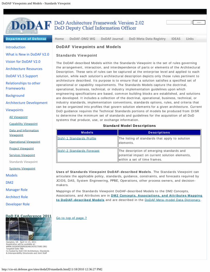
DoDAF Viewpoints and Models - Standards Viewpoint
http://cio-nii.defense.gov/sites/dodaf20/standards.html[11/18/2010 12:36:27 PM]
Home DoDAF-DM2 WG DoDAF Journal DoD Meta Data Registry IDEAS Links
DoDAF Viewpoints and Models
Standards Viewpoint
The DoDAF-described Models within the Standards Viewpoint is the set of rules governingthe arrangement, interaction, and interdependence of parts or elements of the ArchitecturalDescription. These sets of rules can be captured at the enterprise level and applied to eachsolution, while each solution's architectural description depicts only those rules pertinent toarchitecture described. Its purpose is to ensure that a solution satisfies a specified set ofoperational or capability requirements. The Standards Models capture the doctrinal,operational, business, technical, or industry implementation guidelines upon whichengineering specifications are based, common building blocks are established, and solutionsare developed. It includes a collection of the doctrinal, operational, business, technical, orindustry standards, implementation conventions, standards options, rules, and criteria thatcan be organized into profiles that govern solution elements for a given architecture. CurrentDoD guidance requires the Technical Standards portions of models be produced from DISRto determine the minimum set of standards and guidelines for the acquisition of all DoDsystems that produce, use, or exchange information.
Standard Model Descriptions
Models Descriptions
StdV-1 Standards Profile The listing of standards that apply to solutionelements.
StdV-2 Standards Forecast The description of emerging standards andpotential impact on current solution elements,within a set of time frames.
Uses of Standards Viewpoint DoDAF-described Models. The Standards Viewpoint canarticulate the applicable policy, standards, guidance, constraints, and forecasts required byJCIDS, DAS, System Engineering, PPBE, Operations, other process owners, and decision-makers.
Mappings of the Standards Viewpoint DoDAF-described Models to the DM2 Concepts,Associations, and Attributes are in DM2 Concepts, Associations, and Attributes Mappingto DoDAF-described Models and are described in the DoDAF Meta-model Data Dictionary.
Go to top of page ?
Introduction
What is New in DoDAF V2.0
Vision for DoDAF V2.0
Architecture Resources
DoDAF V1.5 Support
Relationships to otherFrameworks
Background
Architecture Development
Viewpoints
All Viewpoint
Capability Viewpoint
Data and InformationViewpoint
Operational Viewpoint
Project Viewpoint
Services Viewpoint
Standards Viewpoint
Systems Viewpoint
Models
DM2
Manager Role
Architect Role
Developer Role
Department of Defense

DoDAF Viewpoints and Models - Standards Viewpoint
http://cio-nii.defense.gov/sites/dodaf20/standards.html[11/18/2010 12:36:27 PM]
Site Map
Privacy Policy | Web Policy | Contact | Submit Change Requests
StdV-1: Standards Profile
http://cio-nii.defense.gov/sites/dodaf20/STDV-1.html[11/18/2010 12:36:37 PM]
Home DoDAF-DM2 WG DoDAF Journal DoD Meta Data Registry IDEAS Links
DoDAF Viewpoints and Models
Standards Viewpoint
StdV-1: Standards Profile
The StdV-1 defines the technical, operational, and business standards, guidance, and policyapplicable to the architecture being described. As well as identifying applicable technicalstandards, the DoDAF V2.0 StdV-1 also documents the policies and standards that apply tothe operational or business context. The DISR is an architecture resource for technicalstandards that can be used in the generation of the StdV-1 and StdV-2 Standards Forecast.
In most cases, building a Standards Profile consists of identifying and listing the applicableportions of existing and emerging documentation. A StdV-1 should identify both existingguidelines, as well as any areas lacking guidance. As with other models, each profile isassigned a specific timescale (e.g., "As-Is", "To-Be", or transitional). Linking the profile to adefined timescale enables the profile to consider both emerging technologies and any currenttechnical standards that are expected to be updated or become obsolete. If more than oneemerging standard time-period is applicable to an architecture, then a StdV-2 StandardsForecast should be completed as well as a StdV-1.
The intended usage of the StdV-1 includes:
Application of standards (informing project strategy).Standards compliance.
Detailed Description:
The StdV-1 collates the various systems and services, standards, and rules that implementand constrain the choices that can be or were made in the design and implementation of anArchitectural Description. It delineates the systems, services, Standards, and rules thatapply. The technical standards govern what hardware and software may be implemented andon what system. The standards that are cited may be international such as ISO standards,national standards, or organizational specific standards.
With associated standards with other elements of the architecture, a distinction is madebetween applicability and conformance. If a standard is applicable to a given architecture,that architecture need not be fully conformant with the standard. The degree of conformanceto a given standard may be judged based on a risk assessment at each approval point.
Note that an association between a Standard and an architectural element should not beinterpreted as indicating that the element is fully compliant with that Standard. Furtherdetail would be needeed to confirm the level of compliance.
Standards Profiles for a particular architecture must maintain full compatibility with the rootstandards they have been derived from. In addition, the StdV-1 model may state a particularmethod of implementation for a Standard, as compliance with a Standard does not ensureinteroperability. The Standards cited are referenced as relationships to the systems, services,system functions, service functions, system data, service data, hardware/software items orcommunication protocols, where applicable, in:
SV-1 Systems Interface Description.SV-2 Systems Resource Flow Description.SV-4 Systems Functionality Description.
Introduction
What is New in DoDAF V2.0
Vision for DoDAF V2.0
Architecture Resources
DoDAF V1.5 Support
Relationships to otherFrameworks
Background
Architecture Development
Viewpoints
All Viewpoint
Capability Viewpoint
Data and InformationViewpoint
Operational Viewpoint
Project Viewpoint
Services Viewpoint
Standards Viewpoint
Systems Viewpoint
Models
DM2
Manager Role
Architect Role
Developer Role
Department of Defense

StdV-1: Standards Profile
http://cio-nii.defense.gov/sites/dodaf20/STDV-1.html[11/18/2010 12:36:37 PM]
SV-6 Systems Resource Flow Matrix.SvcV-1 Services Context Description.SvcV-2 Services Resource Flow Description.SvcV-4 Services Functionality Description.SvcV-6 Services Resource Flow Matrix.DIV-2 Logical Data Model.DIV-3 Physical Data Model.
That is, each standard listed in the profile is associated with the elements that implement oruse the standard.
The protocols referred to Resource Flow descriptions (see SV-2 Systems Resource FlowDescription or SvcV-2 Services Resource Flow Description) are examples of Standards andthese should also be included in the StdV-1 listing, irrespective of which models they appearin or are referred from.
Go to top of page ?
Site Map
Privacy Policy | Web Policy | Contact | Submit Change Requests

StdV-2: Standards Forecast
http://cio-nii.defense.gov/sites/dodaf20/STDV-2.html[11/18/2010 12:37:10 PM]
Home DoDAF-DM2 WG DoDAF Journal DoD Meta Data Registry IDEAS Links
DoDAF Viewpoints and Models
Standards Viewpoint
StdV-2: Standards Forecast
The StdV-2 contains expected changes in technology-related standards, operationalstandards, or business standards and conventions, which are documented in the StdV-1model. The forecast for evolutionary changes in the standards need to be correlated againstthe time periods mentioned in the SV-8 Systems Evolution Description, SvcV-8 ServicesEvolution Description, SV-9 Systems Technology & Skills Forecast, and SvcV-9 ServicesTechnology & Skills Forecast models.
A StdV-2 is a detailed description of emerging standards relevant to the systems,operational, and business activities covered by the Architectural Description. The forecastshould be tailored to focus on areas that are related to the purpose for which a givenArchitectural Description is being built, and should identify issues that affect the architecture.A StdV-2 complements and expands on the StdV-1Standards Profile model and should beused when more than one emerging standard time-period is applicable to the architecture.
One of the prime purposes of this model is to identify critical technology standards, theirfragility, and the impact of these standards on the future development and maintainability ofthe architecture and its constituent elements.
The intended usage of the StdV-2 includes:
Forecasting future changes in standards (informing project strategy).
Detailed Description:
The Standards Forecast DoDAF-described Model contains expected changes in standards andconventions, which are documented in the StdV-1 model. The forecast for evolutionarychanges in the standards need to be correlated against the time periods mentioned in theSV-8 Systems Evolution Description, SvcV-8 Services Evolution Description, SV-9 SystemsTechnology & Skills Forecast, and SvcV-9 Services Technology & Skills Forecast models. Oneof the prime purposes of this model is to identify critical standards, their life expectancy, andthe impact of these standards on the future development and maintainability of theArchitectural Description and its constituent elements.
StdV-2 lists emerging or evolving standards relevant to the solutions covered by theArchitectural Description. It contains predictions about the availability of emerging standards,and relates these predictions to the elements and the time periods that are listed in the SV-8Systems Evolution Description, SvcV-8 Services Evolution Description, SV-9 SystemsTechnology & Skills Forecast, and SvcV-9 Services Technology & Skills Forecast models.
The specific time periods selected (e.g., 6-month and 12-month intervals) and the standardsbeing tracked are coordinated with architecture transition plans (which the SV-8 SystemsEvolution Description and SvcV-8 Services Evolution Description can support). That is,insertion of new capabilities and upgrading of existing solutions may depend on, or be drivenby, the availability of new standards and models incorporating those standards. The forecastspecifies potential standards and thus impacts current architectures and influences thedevelopment of transition and objective (i.e., target) architectures. The forecast is tailored tofocus on standards areas that are related to the purpose for which a given architecture isbeing described and should identify potential standards affecting that architecture. If
Introduction
What is New in DoDAF V2.0
Vision for DoDAF V2.0
Architecture Resources
DoDAF V1.5 Support
Relationships to otherFrameworks
Background
Architecture Development
Viewpoints
All Viewpoint
Capability Viewpoint
Data and InformationViewpoint
Operational Viewpoint
Project Viewpoint
Services Viewpoint
Standards Viewpoint
Systems Viewpoint
Models
DM2
Manager Role
Architect Role
Developer Role
Department of Defense

StdV-2: Standards Forecast
http://cio-nii.defense.gov/sites/dodaf20/STDV-2.html[11/18/2010 12:37:10 PM]
interface standards are an integral part of the technologies important to the evolution of agiven architecture, then it may be convenient to combine StdV-2 with SV-9 SystemsTechnology & Skills Forecast or SvcV-9 Services Technology & Skills Forecast into acomposite Fit-for-Purpose View. For other projects, it may be convenient to combine all thestandards information into one composite Fit-for-Purpose View, combining StdV-2 with StdV-1 Standard Profile.
StdV-2 delineates the standards that potentially impact the relevant system and serviceelements (from SV-1 Systems Interface Description, SV-2 Systems Resource FlowDescription, SV-4 Systems Functionality Description, SV-6 Systems Resource Flow Matrix,SvcV-1 Services Context Description, SvcV-2 Services Resource Flow Description, SvcV-4Services Functionality Description, SV-6 Services Resource Flow Matrix, and DIV-2 LogicalData Model) and relates them to the time periods that are listed in the SV-8 SystemsEvolution Description, SvcV-8 Services Evolution Description, SV-9 Systems Technology &Skills Forecast, and SvcV-9 Services Technology & Skills Forecast models. A system'sevolution, specified in SV-8 Systems Evolution Description, or service's evolutions, specifiedin SvcV-8 Services Evolution Description, may be tied to a future standard listed in StdV-2.A timed technology and skills forecast from SV-9 Systems Technology & Skills Forecast orSvcV-9 Services Technology & Skills Forecast models is related to StdV-2 standards forecastin the following manner: a certain technology may be dependent on a StdV-2 standard (i.e.,a standard listed in StdV-2 may not be adopted until a certain technology becomesavailable). This is how a prediction on the adoption of a future standard, may be related tostandards listed in StdV-1 through the SV-9 Systems Technology & Skills Forecast or SvcV-9Services Technology & Skills Forecast models.
Go to top of page ?
Site Map
Privacy Policy | Web Policy | Contact | Submit Change Requests
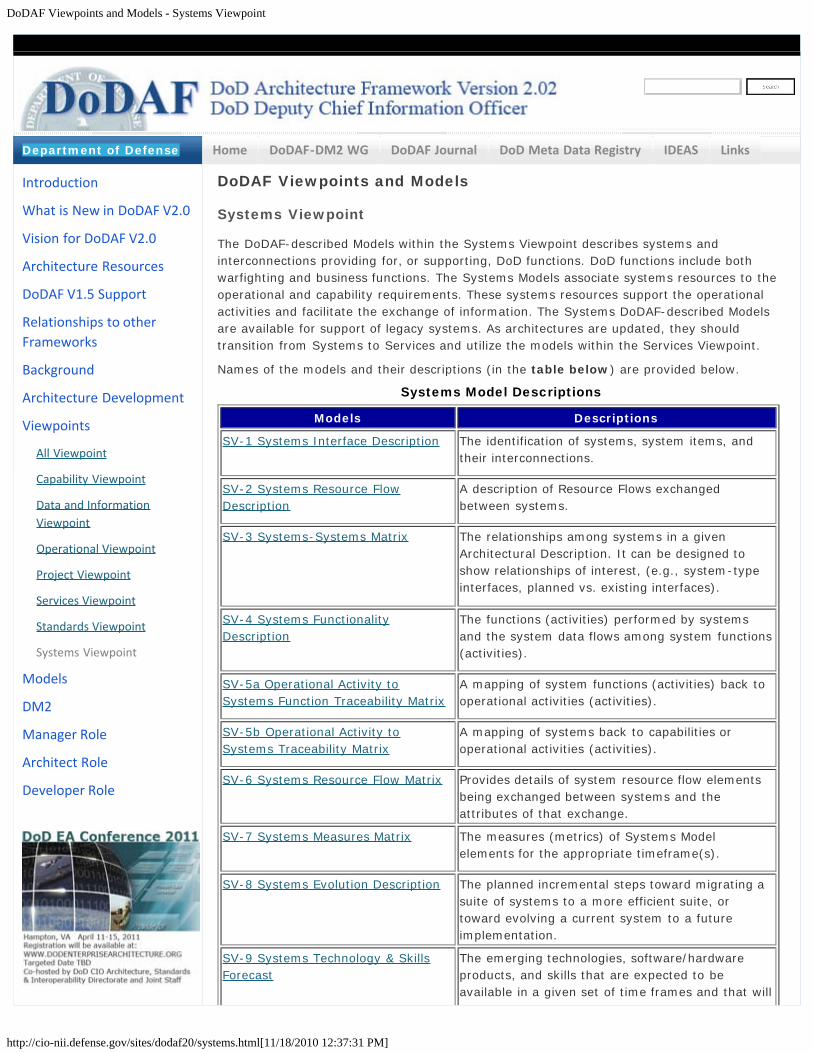
DoDAF Viewpoints and Models - Systems Viewpoint
http://cio-nii.defense.gov/sites/dodaf20/systems.html[11/18/2010 12:37:31 PM]
Home DoDAF-DM2 WG DoDAF Journal DoD Meta Data Registry IDEAS Links
DoDAF Viewpoints and Models
Systems Viewpoint
The DoDAF-described Models within the Systems Viewpoint describes systems andinterconnections providing for, or supporting, DoD functions. DoD functions include bothwarfighting and business functions. The Systems Models associate systems resources to theoperational and capability requirements. These systems resources support the operationalactivities and facilitate the exchange of information. The Systems DoDAF-described Modelsare available for support of legacy systems. As architectures are updated, they shouldtransition from Systems to Services and utilize the models within the Services Viewpoint.
Names of the models and their descriptions (in the table below) are provided below.
Systems Model Descriptions
Models Descriptions
SV-1 Systems Interface Description The identification of systems, system items, andtheir interconnections.
SV-2 Systems Resource FlowDescription
A description of Resource Flows exchangedbetween systems.
SV-3 Systems-Systems Matrix The relationships among systems in a givenArchitectural Description. It can be designed toshow relationships of interest, (e.g., system-typeinterfaces, planned vs. existing interfaces).
SV-4 Systems FunctionalityDescription
The functions (activities) performed by systemsand the system data flows among system functions(activities).
SV-5a Operational Activity toSystems Function Traceability Matrix
A mapping of system functions (activities) back tooperational activities (activities).
SV-5b Operational Activity toSystems Traceability Matrix
A mapping of systems back to capabilities oroperational activities (activities).
SV-6 Systems Resource Flow Matrix Provides details of system resource flow elementsbeing exchanged between systems and theattributes of that exchange.
SV-7 Systems Measures Matrix The measures (metrics) of Systems Modelelements for the appropriate timeframe(s).
SV-8 Systems Evolution Description The planned incremental steps toward migrating asuite of systems to a more efficient suite, ortoward evolving a current system to a futureimplementation.
SV-9 Systems Technology & SkillsForecast
The emerging technologies, software/hardwareproducts, and skills that are expected to beavailable in a given set of time frames and that will
Introduction
What is New in DoDAF V2.0
Vision for DoDAF V2.0
Architecture Resources
DoDAF V1.5 Support
Relationships to otherFrameworks
Background
Architecture Development
Viewpoints
All Viewpoint
Capability Viewpoint
Data and InformationViewpoint
Operational Viewpoint
Project Viewpoint
Services Viewpoint
Standards Viewpoint
Systems Viewpoint
Models
DM2
Manager Role
Architect Role
Developer Role
Department of Defense

DoDAF Viewpoints and Models - Systems Viewpoint
http://cio-nii.defense.gov/sites/dodaf20/systems.html[11/18/2010 12:37:31 PM]
affect future system development.
SV-10a Systems Rules Model One of three models used to describe systemfunctionality. It identifies constraints that areimposed on systems functionality due to someaspect of system design or implementation.
SV-10b Systems State TransitionDescription
One of three models used to describe systemfunctionality. It identifies responses of systems toevents.
SV-10c Systems Event-TraceDescription
One of three models used to describe systemfunctionality. It identifies system-specificrefinements of critical sequences of eventsdescribed in the Operational Viewpoint.
Uses of System Viewpoint DoDAF-described Models. Within the development process,the DoDAF-described Models describe the design for system-based solutions to support orenable requirements created by the operational development processes (JCIDS) and DefenseAcquisition System.
Mappings of the Systems Viewpoint DoDAF-described Models, to the DM2 Concepts,Associations, and Attributes are in DM2 Concepts, Associations, and Attributes Mappingto DoDAF-described Models. The DM2 Concepts, Associations, and Attributes aredescribed in the DoDAF Meta-model Data Dictionary.
Go to top of page ?
Site Map
Privacy Policy | Web Policy | Contact | Submit Change Requests

SV-1: Systems Interface Description
http://cio-nii.defense.gov/sites/dodaf20/SV-1.html[11/18/2010 12:42:24 PM]
Home DoDAF-DM2 WG DoDAF Journal DoD Meta Data Registry IDEAS Links
DoDAF Viewpoints and Models
Systems Viewpoint
SV-1: Systems Interface Description
The SV-1 addresses the composition and interaction of Systems. For DoDAF V2.0, the SV-1incorporates the human elements as types of Performers - Organizations and PersonnelTypes.
The SV-1 links together the operational and systems architecture models by depicting howResources are structured and interact to realize the logical architecture specified in an OV-2Operational Resource Flow Description. A SV-1 may represent the realization of arequirement specified in an OV-2 Operational Resource Flow Description (i.e., in a "To-Be"architecture), and so there may be many alternative SV models that could realize theoperational requirement. Alternatively, in an "As-Is" architecture, the OV-2 OperationalResource Flow Description may simply be a simplified, logical representation of the SV-1 toallow communication of key Resource Flows to non-technical stakeholders.
A System Resource Flow is a simplified representation of a pathway or network pattern,usually depicted graphically as a connector (i.e., a line with possible amplifying information).The SV-1 depicts all System Resource Flows between Systems that are of interest. Note thatResource Flows between Systems may be further specified in detail in SV-2 SystemsResource Flow Description and SV-6 Systems Resource Flow Matrix.
Sub-System assemblies may be identified in SV-1 to any level (i.e., depth) of decompositionthe architect sees fit. SV-1 may also identify the Physical Assets (e.g., Platforms) at whichResources are deployed, and optionally overlay Operational Activities and Locations thatutilize those Resources. In many cases, an operational activity and locations depicted in anOV-2 Operational Resource Flow Description model may well be the logical representation ofthe resource that is shown in SV-1.
The intended usage of the SV-1 includes:
Definition of System concepts.Definition of System options.System Resource Flow requirements capture.Capability integration planning.System integration management.Operational planning (capability and performer definition).
The SV-1 is used in two complementary ways:
Describe the Resource Flows exchanged between resources in the architecture.Describe a solution, or solution option, in terms of the components of capability andtheir physical integration on platforms and other facilities.
Detailed Description:
A SV-1 can be used simply to depict Systems and sub-systems and identify the ResourceFlows between them. The real benefit of a SV-1 is its ability to show the human aspects ofan architecture, and how these interact with Systems. In addition, DoDAF has the concept ofCapability and Performers (see Capability Meta-model group in Section 2) which is used to
Introduction
What is New in DoDAF V2.0
Vision for DoDAF V2.0
Architecture Resources
DoDAF V1.5 Support
Relationships to otherFrameworks
Background
Architecture Development
Viewpoints
All Viewpoint
Capability Viewpoint
Data and InformationViewpoint
Operational Viewpoint
Project Viewpoint
Services Viewpoint
Standards Viewpoint
Systems Viewpoint
Models
DM2
Manager Role
Architect Role
Developer Role
Department of Defense

SV-1: Systems Interface Description
http://cio-nii.defense.gov/sites/dodaf20/SV-1.html[11/18/2010 12:42:24 PM]
gather together systems, assets and people into a configuration, which can meet a specificcapability. A primary purpose of a SV-1 DoDAF-described Model is to show resourcestructure, i.e., identify the primary sub-systems, performer and activities (functions) andtheir interactions. SV-1 contributes to user understanding of the structural characteristics ofthe capability.
The physical resources contributing to a capability are either an organizational resource or aphysical asset, i.e., a system cannot contribute alone (it must be hosted on a physical assetused by an organizational resource of both). Organizational aspects can now be shown onSV-1 (e.g., who uses System). Resource structures may be identified in SV-1 to any level(i.e., depth) of decomposition the architect sees fit. DoDAF does not specifically use termssuch as, sub-System and component as these terms often denote a position relative to astructural hierarchy. Any System may combine hardware and software or these can betreated as separate (sub) Systems. DoDAF V2.0 includes human factors (as Personnel Typesand a type of Performer). Should an architect wish to describe a System which has humanelements, then Systems, Personnel Types and Performers should be used to wrap the humanand system elements together.
A SV-1 can optionally be annotated with Operational Activities, Capabilities, and/or Locationsoriginally specified in OV-2 Operational Resource Flow Description model. In this way,traceability can be established from the logical OV structure to the physical SystemViewpoint structure. If possible, a SV-1 shows Systems, Physical Assets and Systeminterfaces for the entire Architectural Description on the same diagram. If a single SV-1 isnot possible, the resource of interest should be decomposed into multiple SV-1 models.
Functions (Activities):
Some Resources can carry out System Functions (Activities) as described in SV-4 SystemsFunctionality Description model and these functions can optionally be overlaid on a SV-1. Ina sense, the SV-1 and the SV-4 Systems Functionality Description model providecomplementary representations (structure and function). Either could be modeled first, butusually an iterative approach is used to model these together gradually building up the levelof detail in the System description. Note that the same type (class) of resource may be usedin different contexts in a given SV-1. For this reason, the tracing of functions to resources isspecified in context of their usage (see DM2 for details).
Resource Flows in SV-1:
In addition to depicting Systems (Performers) and their structure, the SV-1 addressesResource Flows. A Resource Flow, as depicted in SV-1, is an indicator that resources passbetween one System and the other. In the case of Systems, this can be expanded intofurther detail in SV-2 Systems Resource Flow Description.
Interactions are only possible between Systems and Services. System Resource Flowsprovide a specification for how the operational Resource Flows Exchanges specified inNeedlines (in the OV-2 Operational Resource Flow Description model) are realized withSystems. A single Needline shown in the OV-2 Operational Resource Flow Description modelmay translate into multiple System Resource Flows.
The actual implementation of a System Resource Flow may take more than one form (e.g.,multiple physical links). Details of the physical pathways or network patterns that implementthe interfaces are documented in SV-2 Systems Resource Flow Description. SystemResource Flows are summarized in a SV-3b Systems-Systems Matrix. The functionsperformed by the resources are specified in a SV-4 System Functionality Description, butmay optionally be overlaid on the Resources in a SV-1.
An Operational Viewpoint (OV) suite may specify a set of requirements - either as a specificoperational plan, or a scenario for procurement. As OV-2 Operational Resource FlowDescription, OV-5a Operational Activity Decomposition Tree, and OV-5b Operational ActivityModel specify the logical structure and behavior, SV-1 and SV-4 Systems FunctionalityDescription specify the physical structure and behavior (to the level of detail required by thearchitectural stakeholders). This separation of logical and physical presents an opportunity
Site Map

SV-1: Systems Interface Description
http://cio-nii.defense.gov/sites/dodaf20/SV-1.html[11/18/2010 12:42:24 PM]
for carrying out architectural trade studies based on the architectural content in the DoDAF-described Models.
The structural and behavioral models in the OVs and SVs allow architects and stakeholdersto quickly ascertain which functions are carried out by humans and which by Systems foreach alternative specification and so carry out trade analysis based on risk, cost, reliability,etc.
SV-1 Systems Interface Description
SV-2 Systems Resource Flow Description
SV-3 Systems-Systems Matrix
SV-4 Systems Functionality Description
SV-5a Operational Activity to Systems Function Traceability Matrix
SV-5b Operational Activity to Systems Traceability Matrix
SV-6 Systems Resource Flow Matrix
SV-7 Systems Measures Matrix
SV-8 Systems Evolution Description
SV-9 Systems Technology & Skills Forecast
Introduction to SV-10a, SV10b, and SV-10c
SV-10a Systems Rules Model
SV-10b Systems State Transition Description
SV-10c Systems Event-Trace Description
Go to top of page ?
Privacy Policy | Web Policy | Contact | Submit Change Requests

SV-2: Systems Resource Flow Description
http://cio-nii.defense.gov/sites/dodaf20/SV-2.html[11/18/2010 12:42:52 PM]
Home DoDAF-DM2 WG DoDAF Journal DoD Meta Data Registry IDEAS Links
DoDAF Viewpoints and Models
Systems Viewpoint
SV-2: Systems Resource Flow Description
A SV-2 specifies the System Resource Flows between Systems and may also list the protocolstacks used in connections.
A SV-2 DoDAF-described Model is used to give a precise specification of a connectionbetween Systems. This may be an existing connection, or a specification for a connectionthat is to be made.
The intended usage of the SV-2 includes:
Resource Flow specification.
Detailed Description:
A SV-2 comprises Systems, their ports, and the Resource Flows between those ports. Thearchitect may choose to create a diagram for each Resource Flow for all Systems or to showall the Resource Flows on one diagram if possible.
Each SV-2 model can show:
Which ports are connected?The Systems that the ports belong to.The definition of the System Resource Flow in terms of the physical/logicalconnectivity and any protocols that are used in the connection.
Note that networks are represented as Systems. The architect may choose to show otherSystems being components of the network, i.e., if they are part of the networkinfrastructure.
Any protocol referred to in a SV-2 diagram needs to be defined in the StdV-1 StandardsProfile.
SV-1 Systems Interface Description
SV-2 Systems Resource Flow Description
SV-3 Systems-Systems Matrix
SV-4 Systems Functionality Description
SV-5a Operational Activity to Systems Function Traceability Matrix
SV-5b Operational Activity to Systems Traceability Matrix
SV-6 Systems Resource Flow Matrix
SV-7 Systems Measures Matrix
SV-8 Systems Evolution Description
SV-9 Systems Technology & Skills Forecast
Introduction to SV-10a, SV10b, and SV-10c
SV-10a Systems Rules Model
Introduction
What is New in DoDAF V2.0
Vision for DoDAF V2.0
Architecture Resources
DoDAF V1.5 Support
Relationships to otherFrameworks
Background
Architecture Development
Viewpoints
All Viewpoint
Capability Viewpoint
Data and InformationViewpoint
Operational Viewpoint
Project Viewpoint
Services Viewpoint
Standards Viewpoint
Systems Viewpoint
Models
DM2
Manager Role
Architect Role
Developer Role
Department of Defense
SV-2: Systems Resource Flow Description
http://cio-nii.defense.gov/sites/dodaf20/SV-2.html[11/18/2010 12:42:52 PM]
SV-10b Systems State Transition Description
SV-10c Systems Event-Trace Description
Go to top of page ?
Site Map
Privacy Policy | Web Policy | Contact | Submit Change Requests

SV-3: Systems-Systems Matrix
http://cio-nii.defense.gov/sites/dodaf20/SV-3.html[11/18/2010 12:43:01 PM]
Home DoDAF-DM2 WG DoDAF Journal DoD Meta Data Registry IDEAS Links
DoDAF Viewpoints and Models
Systems Viewpoint
SV-3: Systems-Systems Matrix
A SV-3 enables a quick overview of all the system resource interactions specified in one ormore SV-1 Systems Interface Description models. The SV-3 provides a tabular summary ofthe system interactions specified in the SV-1 Systems Interface Description model for theArchitectural Description. The matrix format supports a rapid assessment of potentialcommonalities and redundancies (or, if fault-tolerance is desired, the lack of redundancies).
The SV-3 can be organized in a number of ways to emphasize the association of groups ofsystem pairs in context with the architecture's purpose.
The intended usage of the SV-3 includes:
Summarizing system resource interactions.Interface management.Comparing interoperability characteristics of solution options.
Detailed Description:
The SV-1 concentrates on System resources and their interactions, and these aresummarized in a SV-3. The SV-3 can be a useful tool for managing the evolution of solutionsand infrastructures, the insertion of new technologies and functionality, and theredistribution of systems and activities in context with evolving operational requirements.
Depending upon the purpose of the Architectural Description, there could be several SV-3s.The suite of SV-3 models can be organized in a number of ways (e.g., by domain, byoperational mission phase, by solution option) to emphasize the association of groups ofresource pairs in context with the Architectural Description purpose.
The SV-3 is generally presented as a matrix, where the Systems resources are listed in therows and columns of the matrix, and each cell indicates an interaction between resources ifone exists. Many types of interaction information can be presented in the cells of a SV-3.The resource interactions can be represented using different symbols and/or color codingthat depicts different interaction characteristics, for example:
Status (e.g., existing, planned, potential, de-activated).Key interfaces.Category (e.g., command and control, intelligence, personnel, logistics).Classification-level (e.g., Restricted, Confidential, Secret, Top Secret).Communication means (e.g., Rim Loop Interface, Scalable Loop Interface).
DoDAF does not specify the symbols to be used. If symbols are used, a key is needed.
SV-1 Systems Interface Description
SV-2 Systems Resource Flow Description
SV-3 Systems-Systems Matrix
SV-4 Systems Functionality Description
SV-5a Operational Activity to Systems Function Traceability Matrix
Introduction
What is New in DoDAF V2.0
Vision for DoDAF V2.0
Architecture Resources
DoDAF V1.5 Support
Relationships to otherFrameworks
Background
Architecture Development
Viewpoints
All Viewpoint
Capability Viewpoint
Data and InformationViewpoint
Operational Viewpoint
Project Viewpoint
Services Viewpoint
Standards Viewpoint
Systems Viewpoint
Models
DM2
Manager Role
Architect Role
Developer Role
Department of Defense

SV-3: Systems-Systems Matrix
http://cio-nii.defense.gov/sites/dodaf20/SV-3.html[11/18/2010 12:43:01 PM]
SV-5b Operational Activity to Systems Traceability Matrix
SV-6 Systems Resource Flow Matrix
SV-7 Systems Measures Matrix
SV-8 Systems Evolution Description
SV-9 Systems Technology & Skills Forecast
Introduction to SV-10a, SV10b, and SV-10c
SV-10a Systems Rules Model
SV-10b Systems State Transition Description
SV-10c Systems Event-Trace Description
Go to top of page ?
Site Map
Privacy Policy | Web Policy | Contact | Submit Change Requests

SV-4: Systems Functionality Description
http://cio-nii.defense.gov/sites/dodaf20/SV-4.html[11/18/2010 12:43:12 PM]
Home DoDAF-DM2 WG DoDAF Journal DoD Meta Data Registry IDEAS Links
DoDAF Viewpoints and Models
Systems Viewpoint
SV-4: Systems Functionality Description
The SV-4 addresses human and system functionality.
The primary purposes of SV-4 are to:
. Develop a clear description of the necessary data flows that are input (consumed) by andoutput (produced) by each resource. . Ensure that the functional connectivity is complete(i.e., that a resource's required inputs are all satisfied). . Ensure that the functionaldecomposition reaches an appropriate level of detail.
The Systems Functionality Description provides detailed information regarding the:
. Allocation of functions to resources. . Flow of resources between functions.
The SV-4 is the Systems Viewpoint model counterpart to the OV-5b Activity Model of theOperational Viewpoint.
The intended usage of the SV-4 includes:
Description of task workflow.Identification of functional system requirements.Functional decomposition of systems.Relate human and system functions.
Detailed Description:
The SV-4 is used to specify the functionality of resources in the architecture (in this case,functional resources, systems, performer and capabilities). The SV-4 is the behavioralcounterpart to the SV-1 Systems Interface Description (in the same way that OV-5bOperational Activity Model is the behavioral counterpart to OV-2 Operational Resource FlowMatrix).
The scope of this model may be capability wide, without regard to which resources performwhich functions, or it may be resource-specific. Variations may focus on intra- or inter-resource data flows, or may simply allocate functions to resources.
There are two basic ways to depict SV-4:
The Taxonomic Functional Hierarchy shows a decomposition of functions depicted in atree structure and is typically used where tasks are concurrent but dependent, such asa production line, for example.The Data Flow Diagram shows functions connected by data flow arrows and datastores.
The Taxonomic Functional Hierarchy may be particularly useful in capability-basedprocurement where it is necessary to model the functions that are associated with particularcapability (see SV-5).
Within an Architectural Description, the SV-4 documents system functions, the ResourceFlows between those functions, the internal system data repositories or system data stores,and the external producers and consumers for the system data flows, but not those external
Introduction
What is New in DoDAF V2.0
Vision for DoDAF V2.0
Architecture Resources
DoDAF V1.5 Support
Relationships to otherFrameworks
Background
Architecture Development
Viewpoints
All Viewpoint
Capability Viewpoint
Data and InformationViewpoint
Operational Viewpoint
Project Viewpoint
Services Viewpoint
Standards Viewpoint
Systems Viewpoint
Models
DM2
Manager Role
Architect Role
Developer Role
Department of Defense

SV-4: Systems Functionality Description
http://cio-nii.defense.gov/sites/dodaf20/SV-4.html[11/18/2010 12:43:12 PM]
to the Architectural Description scope. They may also show how users behave in relation tothose systems.
The functions are likely to be related to Operational Activities captured in OV-5a. Althoughthere is a correlation between the Operational Activity Model (OV-5b) and the functionalhierarchy of SV-4, it need not be a one-to-one mapping, hence, the need for the Functionto Operational Activity Traceability Matrix (SV-5), which provides that mapping.
Systems are not limited to internal system functions and can include HCI and GUI functionsor functions that consume or produce system data. The external system data producers orconsumers can be used to represent the human that interacts with the system. The SystemResource Flows between the external system data source/sink (representing the human orsystem) and the HCI, GUI, or interface function can be used to represent human-systeminteractions, or system-system interfaces. Standards that apply to system functions, such asHCI and GUI standards, are also specified during development of this model (and recorded inStdV-1).
A graphical variant of the SV-4 Data Flow model may be used with swim lanes. A systemswim lane may be associated with:
A System.A grouping of Capabilities and System Functions (usually based on a Physical Asset).A Performer executing an Activity.
Swim lanes are presented either vertically or horizontally. A function can be placed in theswim lane associated with the System, Resources or Performer executing an Activity that itis allocated in the solution architecture. This provides a graphical means of presenting theinteractions between Systems or Capabilities (shown through system connections on SV-1)in functional terms. This is a powerful technique for visualizing the differences betweenalternative solution options (which may have a common set of functions).
SV-1 Systems Interface Description
SV-2 Systems Resource Flow Description
SV-3 Systems-Systems Matrix
SV-4 Systems Functionality Description
SV-5a Operational Activity to Systems Function Traceability Matrix
SV-5b Operational Activity to Systems Traceability Matrix
SV-6 Systems Resource Flow Matrix
SV-7 Systems Measures Matrix
SV-8 Systems Evolution Description
SV-9 Systems Technology & Skills Forecast
Introduction to SV-10a, SV10b, and SV-10c
SV-10a Systems Rules Model
SV-10b Systems State Transition Description
SV-10c Systems Event-Trace Description
Go to top of page ?
Site Map
Privacy Policy | Web Policy | Contact | Submit Change Requests

SV-5a: Operational Activity to Systems Function Traceability Matrix
http://cio-nii.defense.gov/sites/dodaf20/SV-5a.html[11/18/2010 12:43:25 PM]
Home DoDAF-DM2 WG DoDAF Journal DoD Meta Data Registry IDEAS Links
DoDAF Viewpoints and Models
Systems Viewpoint
SV-5a: Operational Activity to Systems Function Traceability Matrix
The SV-5a addresses the linkage between System Functions described in SV-4 SystemsFunctionality Description and Operational Activities specified in OV-5a Operational ActivityDecomposition Tree or OV-5b Operational Activity Model. The SV-5a depicts the mapping ofsystem functions and, optionally, the capabilities and performers that provide them tooperational activities. The SV-5a identifies the transformation of an operational need into apurposeful action performed by a system or solution.
During requirements definition, the SV-5a plays a particularly important role in tracing thearchitectural elements associated with system function requirements to those associatedwith user requirements.
The intended usage of the SV-5a includes:
Tracing functional system requirements to user requirements.Tracing solution options to requirements.Identification of overlaps or gaps.
Detailed Description:
An SV-5a is a specification of the relationships between the set of operational activitiesapplicable to an Architectural Description and the set of system functions applicable to thatArchitectural Description. The relationship between operational activities and systemfunctions can also be expected to be many-to-many (i.e., one activity may be supported bymultiple functions, and one function may support multiple activities). The system functionsshown in the SV-5a may be those associated with capabilities and performers. More focusedSV-5a models might be used to specifically trace system functions to operational activities ifdesired.
DoDAF uses the term Operational Activity in the OVs and the term System Function in theSVs to refer to essentially the same kind of thing; both activities and functions are tasksthat are performed, accept inputs, and develop outputs. The distinction between anOperational Activity and a Function is a question of what and how. The Operational Activityis a specification of what is to be done, regardless of the mechanism used. A SystemFunction is specifies how a resource carries it out. For this reason, SV-5a is a significantmodel, as it ties together the logical specification in the OV-5a with the physical specificationof the SV-4 Systems Functionality Description. System Functions can be carried out byFunctional Resources (systems, performers executing activities, and performers).
The SV-5a is generally presented as a matrix of the relationship between system functionsand operational activities. The SV-5a can show requirements traceability with OperationalActivities on one axis of a matrix, the System Functions on the other axis, and with an X,date, or phase in the intersecting cells, where appropriate.
An alternate version of the tabular SV-5a can allow the implementation status of eachfunction to be shown. In this variant model, each system function-to-operational activitymapping is described by a traffic light symbol that may indicate the status of the systemsupport. DoDAF V2.0 does not prescribe a presentation technique. These symbols are usuallycolored circles with the following possible representations:
Introduction
What is New in DoDAF V2.0
Vision for DoDAF V2.0
Architecture Resources
DoDAF V1.5 Support
Relationships to otherFrameworks
Background
Architecture Development
Viewpoints
All Viewpoint
Capability Viewpoint
Data and InformationViewpoint
Operational Viewpoint
Project Viewpoint
Services Viewpoint
Standards Viewpoint
Systems Viewpoint
Models
DM2
Manager Role
Architect Role
Developer Role
Department of Defense

SV-5a: Operational Activity to Systems Function Traceability Matrix
http://cio-nii.defense.gov/sites/dodaf20/SV-5a.html[11/18/2010 12:43:25 PM]
Red may indicate that the functionality is planned but not developed.Yellow may indicate that partial functionality has been provided (or full functionalityprovided but system has not been fielded).Green may indicate that full functionality has been provided to the field.A blank cell may indicate that there is no system support planned for an OperationalActivity, or that a relationship does not exist between the Operational Activity and theSystem Function.
Care should be taken when publishing a SV-5a with status information. Any presentationshould clearly state the date of publication, so that users can see when status information isold.
SV-5a may be further annotated with Systems, Capabilities, Performers executing Activities,and capabilities and performers that conduct the functions.
SV-1 Systems Interface Description
SV-2 Systems Resource Flow Description
SV-3 Systems-Systems Matrix
SV-4 Systems Functionality Description
SV-5a Operational Activity to Systems Function Traceability Matrix
SV-5b Operational Activity to Systems Traceability Matrix
SV-6 Systems Resource Flow Matrix
SV-7 Systems Measures Matrix
SV-8 Systems Evolution Description
SV-9 Systems Technology & Skills Forecast
Introduction to SV-10a, SV10b, and SV-10c
SV-10a Systems Rules Model
SV-10b Systems State Transition Description
SV-10c Systems Event-Trace Description
Go to top of page ?
Site Map
Privacy Policy | Web Policy | Contact | Submit Change Requests

SV-5b: Operational Activity to Systems Traceability Matrix
http://cio-nii.defense.gov/sites/dodaf20/SV-5b.html[11/18/2010 12:43:35 PM]
Home DoDAF-DM2 WG DoDAF Journal DoD Meta Data Registry IDEAS Links
DoDAF Viewpoints and Models
Systems Viewpoint
SV-5b: Operational Activity to Systems Traceability Matrix
The SV-5b addresses the linkage between described in SV-1 Systems FunctionalityDescription and Operational Activities specified in OV-5a Operational Activity DecompositionTree or OV-5b Operational Activity Model. The SV-5b depicts the mapping of systems and,optionally, the capabilities and performers that provide them to operational activities. TheSV-5b identifies the transformation of an operational need into a purposeful actionperformed by a system or solution.
During requirements definition, the SV-5b plays a particularly important role in tracing thearchitectural elements associated with system requirements to those associated with userrequirements.
The intended usage of the SV-5b includes:
Tracing system requirements to user requirements.Tracing solution options to requirements.Identification of overlaps or gaps.
Detailed Description:
An SV-5b is a specification of the relationships between the set of operational activitiesapplicable to an Architectural Description and the set of systems applicable to thatArchitectural Description. The relationship between operational activities and systems canalso be expected to be many-to-many (i.e., one activity may be supported by multiplesystems, and one system may support multiple activities). The system shown in the SV-5bmay be those associated with resources. More focused SV-5b models might be used tospecifically trace system to operational activities if desired.
The SV-5b is generally presented as a matrix of the relationship between systems andactivities and can be a summary of the Operational Activity to System Function TraceabilityMatrix (SV-5a). The SV-5b can show requirements traceability with Operational Activities onone axis of a matrix, the System Functions on the other axis, and with an X, date, or phasein the intersecting cells, where appropriate.
An alternate version of the tabular SV-5b model can allow the implementation status of eachsystem to be shown. In this variant model, each system-to-operational activity mapping isdescribed by a traffic light symbol that may indicate the status of the system support.DoDAF V2.0 does not prescribe a presentation technique. These symbols are usually coloredcircles with the following possible representations:
Red may indicate that the system is planned but not developed.Yellow may indicate that partial system functionality has been provided (or fullfunctionality provided but system has not been fielded).Green may indicate that full system functionality has been provided to the field.A blank cell may indicate that there is no system support planned for an OperationalActivity, or that a relationship does not exist between the Operational Activity and theSystem Function.
Introduction
What is New in DoDAF V2.0
Vision for DoDAF V2.0
Architecture Resources
DoDAF V1.5 Support
Relationships to otherFrameworks
Background
Architecture Development
Viewpoints
All Viewpoint
Capability Viewpoint
Data and InformationViewpoint
Operational Viewpoint
Project Viewpoint
Services Viewpoint
Standards Viewpoint
Systems Viewpoint
Models
DM2
Manager Role
Architect Role
Developer Role
Department of Defense

SV-5b: Operational Activity to Systems Traceability Matrix
http://cio-nii.defense.gov/sites/dodaf20/SV-5b.html[11/18/2010 12:43:35 PM]
Care should be taken when publishing a SV-5b with status information. Any presentationshould clearly state the date of publication, so that users can see when status information isold.
The SV-5b may be further annotated with Capabilities, Performers executing Activities, andcapabilities and performers that conduct the functions. This can be used to identify whichsystems can support a particular capability. The architect may also wish to hide the systemsin a SV-5b so that the table simply shows the mapping from performers executing activities,and capabilities and performers to Operational Activities.
SV-1 Systems Interface Description
SV-2 Systems Resource Flow Description
SV-3 Systems-Systems Matrix
SV-4 Systems Functionality Description
SV-5a Operational Activity to Systems Function Traceability Matrix
SV-5b Operational Activity to Systems Traceability Matrix
SV-6 Systems Resource Flow Matrix
SV-7 Systems Measures Matrix
SV-8 Systems Evolution Description
SV-9 Systems Technology & Skills Forecast
Introduction to SV-10a, SV10b, and SV-10c
SV-10a Systems Rules Model
SV-10b Systems State Transition Description
SV-10c Systems Event-Trace Description
Go to top of page ?
Site Map
Privacy Policy | Web Policy | Contact | Submit Change Requests

SV-6: Systems Resource Flow Matrix
http://cio-nii.defense.gov/sites/dodaf20/SV-6.html[11/18/2010 12:43:44 PM]
Home DoDAF-DM2 WG DoDAF Journal DoD Meta Data Registry IDEAS Links
DoDAF Viewpoints and Models
Systems Viewpoint
SV-6: Systems Resource Flow Matrix
The SV-6 specifies the characteristics of the System Resource Flows exchanged betweensystems with emphasis on resources crossing the system boundary.
The SV-6 focuses on the specific aspects of the system Resource Flow and the systemResource Flow content in a tabular format.
The intended usage of the SV-6 includes:
Detailed definition of Resource Flows.
Detailed Description:
The SV-6 specifies the characteristics of Resource Flow exchanges between systems. TheSV-6 is the physical equivalent of the logical OV-3 table and provides detailed information onthe system connections which implement the Resource Flow exchanges specified in OV-3.Non-automated Resource Flow exchanges, such as verbal orders, are also captured.
System Resource Flow exchanges express the relationship across the three basicarchitectural data elements of a SV (systems, system functions, and system Resource Flows)and focus on the specific aspects of the System Resource Flow and the system resourcecontent. These aspects of the System Resource Flow exchange can be crucial to theoperational mission and are critical to understanding the potential for overhead andconstraints introduced by the physical aspects of the implementation such as security policyand communications limitations.
The focus of SV-6 is on how the System Resource Flow exchange is affected, in system-specific details covering periodicity, timeliness, throughput, size, information assurance, andsecurity characteristics of the resource exchange. In addition, the System Resource Flowelements, their format and media type, accuracy, units of measurement, and system datastandard are also described in the matrix.
Modeling discipline is needed to ensure that the architecture models are coherent. Eachsystem Resource Flow exchange listed in the SV-6 table should be traceable to at least oneoperational Resource Flow exchanged listed in the corresponding OV-3 Operational ResourceFlow Matrix and these, in turn, trace to operation Resource Flows in the OV-2 OperationalResource Flow Description.
It should be noted that each data element exchanged may be related to the system function(from SV-4) that produces or consumes it. However, there need not be a one-to-onecorrelation between data elements listed in the SV-6 matrix and the data flows (inputs andoutputs) that are produced or consumed in a related SV-4 Services Functionality Description.In addition, Data flows between system functions performed by the same systems may notbe shown in the SV-6 matrix. SV-6 is about showing flows across system boundaries.
The SV-7 System Measures Matrix model builds on the SV-6 and should be developed at thesame time.
DoDAF does not prescribe the column headings in a SV-6 Matrix. Identifiers of theoperational Resource Flows from the OV-3 Operational Resource Flow Matrix that are
Introduction
What is New in DoDAF V2.0
Vision for DoDAF V2.0
Architecture Resources
DoDAF V1.5 Support
Relationships to otherFrameworks
Background
Architecture Development
Viewpoints
All Viewpoint
Capability Viewpoint
Data and InformationViewpoint
Operational Viewpoint
Project Viewpoint
Services Viewpoint
Standards Viewpoint
Systems Viewpoint
Models
DM2
Manager Role
Architect Role
Developer Role
Department of Defense

SV-6: Systems Resource Flow Matrix
http://cio-nii.defense.gov/sites/dodaf20/SV-6.html[11/18/2010 12:43:44 PM]
implemented by the System Resource Flow Exchanges may be included in the table. Allelements carried by the Resource Flow exchanges may be also shown.
SV-1 Systems Interface Description
SV-2 Systems Resource Flow Description
SV-3 Systems-Systems Matrix
SV-4 Systems Functionality Description
SV-5a Operational Activity to Systems Function Traceability Matrix
SV-5b Operational Activity to Systems Traceability Matrix
SV-6 Systems Resource Flow Matrix
SV-7 Systems Measures Matrix
SV-8 Systems Evolution Description
SV-9 Systems Technology & Skills Forecast
Introduction to SV-10a, SV10b, and SV-10c
SV-10a Systems Rules Model
SV-10b Systems State Transition Description
SV-10c Systems Event-Trace Description
Go to top of page ?
Site Map
Privacy Policy | Web Policy | Contact | Submit Change Requests

SV-7: Systems Measures Matrix
http://cio-nii.defense.gov/sites/dodaf20/SV-7.html[11/18/2010 12:43:54 PM]
Home DoDAF-DM2 WG DoDAF Journal DoD Meta Data Registry IDEAS Links
DoDAF Viewpoints and Models
Systems Viewpoint
SV-7: Systems Measures Matrix
The SV-7 depicts the measures (metrics) of resources. The Systems Measures Matrixexpands on the information presented in a SV-1 by depicting the characteristics of theresources in the SV-1.
The intended usage of the SV-7 includes:
Definition of performance characteristics and measures (metrics).Identification of non-functional requirements.
Detailed Description:
The SV-7 specifies qualitative and quantitative measures (metrics) of resources; it specifiesall of the measures. The measures are selected by the end user community and described bythe architect.
Performance parameters include all performance characteristics for which requirements canbe developed and specifications defined. The complete set of performance parameters maynot be known at the early stages of Architectural Description, so it is to be expected that thismodel is updated throughout the specification, design, development, testing, and possiblyeven its deployment and operations lifecycle phases. The performance characteristics arecaptured in the Measures Meta-model group.
One of the primary purposes of SV-7 is to communicate which measures are consideredmost crucial for the successful achievement of the mission goals assigned and how thoseperformance parameters will be met. These particular measures can often be the decidingfactors in acquisition and deployment decisions, and figures strongly in systems analysis andsimulations done to support the acquisition decision processes and system designrefinement. Measures of Effectiveness (MOEs) and Measures of Performers (MOPs) aremeasures that can be captured and presented in the Services Measures Matrix model.
The SV-7 DoDAF-described Model is typically a table listing user defined measures (metrics)with a time period association. It is sometimes useful to analyze evolution by comparingmeasures (metrics) for current and future resources. For this reason, a hybrid SV-7 modelwhich spans architectures across multiple phases may be useful.
SV-1 Systems Interface Description
SV-2 Systems Resource Flow Description
SV-3 Systems-Systems Matrix
SV-4 Systems Functionality Description
SV-5a Operational Activity to Systems Function Traceability Matrix
SV-5b Operational Activity to Systems Traceability Matrix
SV-6 Systems Resource Flow Matrix
SV-7 Systems Measures Matrix
SV-8 Systems Evolution Description
Introduction
What is New in DoDAF V2.0
Vision for DoDAF V2.0
Architecture Resources
DoDAF V1.5 Support
Relationships to otherFrameworks
Background
Architecture Development
Viewpoints
All Viewpoint
Capability Viewpoint
Data and InformationViewpoint
Operational Viewpoint
Project Viewpoint
Services Viewpoint
Standards Viewpoint
Systems Viewpoint
Models
DM2
Manager Role
Architect Role
Developer Role
Department of Defense

SV-7: Systems Measures Matrix
http://cio-nii.defense.gov/sites/dodaf20/SV-7.html[11/18/2010 12:43:54 PM]
SV-9 Systems Technology & Skills Forecast
Introduction to SV-10a, SV10b, and SV-10c
SV-10a Systems Rules Model
SV-10b Systems State Transition Description
SV-10c Systems Event-Trace Description
Go to top of page ?
Site Map
Privacy Policy | Web Policy | Contact | Submit Change Requests

SV-8: Systems Evolution Description
http://cio-nii.defense.gov/sites/dodaf20/SV-8.html[11/18/2010 12:44:04 PM]
Home DM2 WG DoDAF Journal DoDAF Meta Data Registry IDEAS Links
DoDAF Viewpoints and Models
Systems Viewpoint
SV-8: Systems Evolution Description
The SV-8 presents a whole lifecycle view of resources (systems), describing how theychange over time. It shows the structure of several resources mapped against a timeline.
The intended usage of the SV-8 includes:
Development of incremental acquisition strategy.Planning technology insertion.
Detailed Description:
The SV-8, when linked together with other evolution Models, e.g., such as CV-3 CapabilityPhasing and StdV-2 Standards Forecast, provides a rich definition of how the Enterprise andits capabilities are expected to evolve over time. In this manner, the model can be used tosupport an architecture evolution project plan or transition plan.
A SV-8 can either describe historical (legacy), current, and future capabilities against atimeline. The model shows the structure of each resource, using similar modeling elementsas those used in SV-1. Interactions which take place within the resource may also be shown.
The changes depicted in the SV-8 are derived from the project milestones that are shown ina PV-2 Project Timelines. When the PV-2 Project Timelines is used for capability acquisitionprojects, there is likely to be a close relationship between these two models.
SV-1 Systems Interface Description
SV-2 Systems Resource Flow Description
SV-3 Systems-Systems Matrix
SV-4 Systems Functionality Description
SV-5a Operational Activity to Systems Function Traceability Matrix
SV-5b Operational Activity to Systems Traceability Matrix
SV-6 Systems Resource Flow Matrix
SV-7 Systems Measures Matrix
SV-8 Systems Evolution Description
SV-9 Systems Technology & Skills Forecast
Introduction to SV-10a, SV10b, and SV-10c
SV-10a Systems Rules Model
SV-10b Systems State Transition Description
SV-10c Systems Event-Trace Description
Introduction
What is New in DoDAF V2.0
Vision for DoDAF V2.0
Architecture Resources
DoDAF V1.5 Support
Relationships to otherFrameworks
Background
Architecture Development
Viewpoints
All Viewpoint
Capability Viewpoint
Data and InformationViewpoint
Operational Viewpoint
Project Viewpoint
Services Viewpoint
Standards Viewpoint
Systems Viewpoint
Models
DM2
Manager Role
Architect Role
Developer Role
Department of Defense

SV-8: Systems Evolution Description
http://cio-nii.defense.gov/sites/dodaf20/SV-8.html[11/18/2010 12:44:04 PM]
Go to top of page ?
Site Map
Privacy Policy | Web Policy | Contact | Submit Change Requests

SV-9: Systems Technology and Skills Forecast
http://cio-nii.defense.gov/sites/dodaf20/SV-9.html[11/18/2010 12:44:12 PM]
Home DoDAF-DM2 WG DoDAF Journal DoD Meta Data Registry IDEAS Links
DoDAF Viewpoints and Models
Systems Viewpoint
SV-9: Systems Technology and Skills Forecast
The SV-9 defines the underlying current and expected supporting technologies and skills.Expected supporting technologies and skills are those that can be reasonably forecast giventhe current state of technology and skills as well as the expected improvements or trends.New technologies and skills are tied to specific time periods, which can correlate against thetime periods used in SV-8 milestones and linked to Capability Phases.
The SV-9 provides a summary of emerging technologies and skills that impact thearchitecture. The SV-9 provides descriptions of relevant:
Emerging capabilities.Industry trends.Predictions (with associated confidence factors) of the availability and readiness ofspecific hardware and software systems.Current and possible future skills.
In addition to providing an inventory of trends, capabilities and systems, the DoDAF-described Model SV-9 also includes an assessment of the potential impact of these items onthe architecture. Given the future-oriented nature of this model, forecasts are typically madein short, mid and long-term timeframes, such as 6, 12 and 18-month intervals.
The intended usage of the SV-9 includes:
Forecasting technology readiness against time.HR Trends Analysis.Recruitment Planning.Planning technology insertion.Input to options analysis.
The SV-9 can be presented in a table, timeline, or a Herringbone diagram.
Detailed Description:
A SV-9 summarizes predictions about trends in technology and personnel. Architects mayproduce separate SV-9 products for technology and human resources. The specific timeperiods selected (and the trends being tracked) are coordinated with architecture transitionplans (which the SV-8 Systems Evolution Description model can support). That is, insertionof new capabilities and upgrading or re-training of existing resources may depend on or bedriven by the availability of new technology and associated skills. The forecast includespotential impacts on current architectures and thus influences the development of transitionand target architectures. The forecast is focused on technology and human resource areasthat are related to the purpose for which a given architecture is being described andidentifies issues affecting that architecture.
If standards are an integral part of the technologies important to the evolution of a givenarchitecture, then it may be convenient to combine SV-9 with the StdV-2 Standards Forecastin a composite Fit-for-Purpose View.
The SV-9 is constructed as part of a given Architectural Description and in accordance with
Introduction
What is New in DoDAF V2.0
Vision for DoDAF V2.0
Architecture Resources
DoDAF V1.5 Support
Relationships to otherFrameworks
Background
Architecture Development
Viewpoints
All Viewpoint
Capability Viewpoint
Data and InformationViewpoint
Operational Viewpoint
Project Viewpoint
Services Viewpoint
Standards Viewpoint
Systems Viewpoint
Models
DM2
Manager Role
Architect Role
Developer Role
Department of Defense

SV-9: Systems Technology and Skills Forecast
http://cio-nii.defense.gov/sites/dodaf20/SV-9.html[11/18/2010 12:44:12 PM]
the Architectural Description purpose. Typically, this involves starting with one or moreoverarching reference models or standards profiles to which the architecture must conform.Using these reference models or standards profiles, the architect selects the service areasand services relevant to the architecture. The SV-9 DoDAF-described Model forecasts relatesto the Standards Profile (StdV-1) in that a timed forecast may contribute to the decision toretire or phase out the use of a certain standard in connection with a resource. Similarly,SV-9 forecasts relate to the Standards Forecasts (StdV-2) in that a certain standard may beadopted depending on a certain technology or skill becoming available (e.g., the availabilityof Java Script may influence the decision to adopt a new HTML standard).
Alternatively, the SV-9 may relate forecasts to SV elements (e.g., systems) whereapplicable. The list of resources potentially impacted by the forecasts can also besummarized as additional information in a SV-9.
SV-1 Systems Interface Description
SV-2 Systems Resource Flow Description
SV-3 Systems-Systems Matrix
SV-4 Systems Functionality Description
SV-5a Operational Activity to Systems Function Traceability Matrix
SV-5b Operational Activity to Systems Traceability Matrix
SV-6 Systems Resource Flow Matrix
SV-7 Systems Measures Matrix
SV-8 Systems Evolution Description
SV-9 Systems Technology & Skills Forecast
Introduction to SV-10a, SV10b, and SV-10c
SV-10a Systems Rules Model
SV-10b Systems State Transition Description
SV-10c Systems Event-Trace Description
Go to top of page ?
Site Map
Privacy Policy | Web Policy | Contact | Submit Change Requests

Introduction to SV-10a, SV-10b and SV-10c
http://cio-nii.defense.gov/sites/dodaf20/SV-10intro.html[11/18/2010 12:44:24 PM]
Home DoDAF-DM2 WG DoDAF Journal DoD Meta Data Registry IDEAS Links
DoDAF Viewpoints and Models
Systems Viewpoint
Introduction to SV-10a, SV-10b and SV-10c
Many of the critical characteristics of an architecture are only discovered when anarchitecture's dynamic behaviors are defined and described. These dynamic behaviorsconcern the timing and sequencing of events that capture resource performancecharacteristics (i.e., a performer executing the system functions described in SV-4).
Behavioral modeling and documentation are key to a successful Architectural Description,because it describes how the architecture behaves which is crucial in many situations.Although knowledge of the functions and interfaces is also crucial, knowing whether, forexample, a response should be expected after sending message X to System Function Y canbe crucial to successful overall operations.
The SV-10 DoDAF-described Models are useful in support of net-centric (service-oriented)implementation of services as orchestrations of services. The SV-3 Systems-Systems Matrixcan provide input for the SV-10 DoDAF-described Models. Three types of models may beused to adequately describe the dynamic behavior and performance characteristics ofSystem elements. These three models are:
Systems Rules Model (SV-10a).Systems State Transition Description (SV-10b).Systems Event-Trace Description (SV-10c).
SV-10b and SV-10c may be used separately or together, as necessary, to describe criticaltiming and sequencing behavior in the SV. Both types of diagrams are used by a wide varietyof different systems methodologies.
Both SV-10b and SV-10c describe functional responses to sequences of events. Events mayalso be referred to as inputs, transactions, or triggers. When an event occurs, the action tobe taken may be subject to a rule or set of rules as described in SV-10a.
SV-1 Systems Interface Description
SV-2 Systems Resource Flow Description
SV-3 Systems-Systems Matrix
SV-4 Systems Functionality Description
SV-5a Operational Activity to Systems Function Traceability Matrix
SV-5b Operational Activity to Systems Traceability Matrix
SV-6 Systems Resource Flow Matrix
SV-7 Systems Measures Matrix
SV-8 Systems Evolution Description
SV-9 Systems Technology & Skills Forecast
Introduction to SV-10a, SV10b, and SV-10c
SV-10a Systems Rules Model
Introduction
What is New in DoDAF V2.0
Vision for DoDAF V2.0
Architecture Resources
DoDAF V1.5 Support
Relationships to otherFrameworks
Background
Architecture Development
Viewpoints
All Viewpoint
Capability Viewpoint
Data and InformationViewpoint
Operational Viewpoint
Project Viewpoint
Services Viewpoint
Standards Viewpoint
Systems Viewpoint
Models
DM2
Manager Role
Architect Role
Developer Role
Department of Defense

Introduction to SV-10a, SV-10b and SV-10c
http://cio-nii.defense.gov/sites/dodaf20/SV-10intro.html[11/18/2010 12:44:24 PM]
SV-10b Systems State Transition Description
SV-10c Systems Event-Trace Description
Go to top of page ?
Site Map
Privacy Policy | Web Policy | Contact | Submit Change Requests

SV-10a: Systems Rules Model
http://cio-nii.defense.gov/sites/dodaf20/SV-10a.html[11/18/2010 12:44:32 PM]
Home DoDAF-DM2 WG DoDAF Journal DoD Meta Data Registry IDEAS Links
DoDAF Viewpoints and Models
Systems Viewpoint
SV-10a: Systems Rules Model
The SV-10a specifies functional and non-functional constraints on the implementationaspects of the architecture (i.e., the structural and behavioral elements of the SystemsViewpoint).
The SV-10a DoDAF-described Model describes constraints on the resources, functions, data,and ports that make up the SV physical architecture. The constraints are specified in textand may be functional or structural (i.e., non-functional).
The intended usage of the SV-10a includes:
Definition of implementation logic.Identification of resource constraints.
Detailed Description:
The Systems Rules Model DoDAF-described Model describes the rules that control, constrainor otherwise guide the implementation aspects of the architecture. System Rules arestatements that define or constrain some aspect of the business, and may be applied to:
Performers.Resource Flows.System Functions.System Ports.Data Elements.
In contrast to the OV-6a Operational Rules Model, SV-10a focuses on physical and dataconstraints rather than business rules.
Constraints can be categorized as follows:
Structural Assertions - non-functional constraints governing some physical aspect ofthe architecture.Action Assertions - functional constraints governing the behavior of resources, theirinteractions and Resource Flow exchanges.Derivations - these involve algorithms used to compute facts.
Where a System Rule is based on some standard, then that standard should be listed in theStdV-1 Standards Profile.
Some System Rules can be added as annotations to other models. The SV-10a then shouldprovide a listing of the complete set of rules with a reference to any models that they affect.
SV-1 Systems Interface Description
SV-2 Systems Resource Flow Description
SV-3 Systems-Systems Matrix
SV-4 Systems Functionality Description
Introduction
What is New in DoDAF V2.0
Vision for DoDAF V2.0
Architecture Resources
DoDAF V1.5 Support
Relationships to otherFrameworks
Background
Architecture Development
Viewpoints
All Viewpoint
Capability Viewpoint
Data and InformationViewpoint
Operational Viewpoint
Project Viewpoint
Services Viewpoint
Standards Viewpoint
Systems Viewpoint
Models
DM2
Manager Role
Architect Role
Developer Role
Department of Defense
SV-10a: Systems Rules Model
http://cio-nii.defense.gov/sites/dodaf20/SV-10a.html[11/18/2010 12:44:32 PM]
SV-5a Operational Activity to Systems Function Traceability Matrix
SV-5b Operational Activity to Systems Traceability Matrix
SV-6 Systems Resource Flow Matrix
SV-7 Systems Measures Matrix
SV-8 Systems Evolution Description
SV-9 Systems Technology & Skills Forecast
Introduction to SV-10a, SV10b, and SV-10c
SV-10a Systems Rules Model
SV-10b Systems State Transition Description
SV-10c Systems Event-Trace Description
Go to top of page ?
Site Map
Privacy Policy | Web Policy | Contact | Submit Change Requests
SV-10b: Systems State Transition Description
http://cio-nii.defense.gov/sites/dodaf20/SV-10b.html[11/18/2010 12:44:42 PM]
Home DoDAF-DM2 WG DoDAF Journal DoD Meta Data Registry IDEAS Links
DoDAF Viewpoints and Models
Systems Viewpoint
SV-10b: Systems State Transition Description
The SV-10b is a graphical method of describing a resource (or system function) response tovarious events by changing its state. The diagram basically represents the sets of events towhich the resources in the Activities respond (by taking an action to move to a new state)as a function of its current state. Each transition specifies an event and an action.
The explicit time sequencing of service functions in response to external and internal eventsis not fully expressed in SV-4 Systems Functionality Description. The SV-10b can be used todescribe the explicit sequencing of the functions. Alternatively, SV-10b can be used to reflectexplicit sequencing of the actions internal to a single function, or the sequencing of systemfunctions with respect to a specific resource.
The intended usage of the SV-10b includes:
Definition of states, events and state transitions (behavioral modeling).Identification of constraints.
Detailed Description:
The SV-10b relates events to resource states and describes the transition from one state toanother. The SV-10b is based on the state chart diagram. A state machine is defined as "aspecification that describes all possible behaviors of some dynamic view element. Behavior ismodeled as a traversal of a graph of specific states interconnected by one or more joinedtransition arcs that are triggered by the dispatching of series of event instances. During thistraversal, the state machine executes a series of actions associated with various elements ofthe state machine." State chart diagrams can be unambiguously converted to structuredtextual rules that specify timing aspects of events and the responses to these events, withno loss of meaning. However, the graphical form of the state diagrams can often allow quickanalysis of the completeness of the rule set, and detection of dead ends or missingconditions. These errors, if not detected early during the solution analysis phase, can oftenlead to serious behavioral errors in fielded capabilities, or to expensive correction efforts.
The SV-10b models state transitions from a resource perspective, with a focus on how theresource responds to stimuli (e.g., triggers and events). As in the OV-6b Operational StateTransition Description, these responses may differ depending upon the rule set or conditionsthat apply as well as the resource's state at the time the stimuli is received. A change ofstate is called a transition. Each transition specifies the response based on a specific eventand the current state. Actions may be associated with a given state or with the transitionbetween states. A state and its associated actions specify the response of a resource orfunction, to events. When an event occurs, the next state may vary depending on thecurrent state (and its associated action), the event, and the rule set or guard conditions.
The SV-10b can be used to describe the detailed sequencing of functions described in SV-4Systems Functionality Description. However, the relationship between the actions included inSV-10b and the functions in SV-4 Systems Functionality Description depends on thepurposes of the architecture and the level of abstraction used in the models. The explicitsequencing of functions in response to external and internal events is not fully expressed inSV-4 Systems Functionality Description. SV-10b can be used to reflect explicit sequencing of
Introduction
What is New in DoDAF V2.0
Vision for DoDAF V2.0
Architecture Resources
DoDAF V1.5 Support
Relationships to otherFrameworks
Background
Architecture Development
Viewpoints
All Viewpoint
Capability Viewpoint
Data and InformationViewpoint
Operational Viewpoint
Project Viewpoint
Services Viewpoint
Standards Viewpoint
Systems Viewpoint
Models
DM2
Manager Role
Architect Role
Developer Role
Department of Defense

SV-10b: Systems State Transition Description
http://cio-nii.defense.gov/sites/dodaf20/SV-10b.html[11/18/2010 12:44:42 PM]
the functions, the sequencing of actions internal to a single function, or the sequencing offunctions with respect to a specific resource.
States in a SV-10b model may be nested. This enables quite complex models to be createdto represent systems behavior. Depending upon the architecture project's needs, the SV-10bmay be used separately or in conjunction with the SV-10c Systems Event-Trace Description.
SV-1 Systems Interface Description
SV-2 Systems Resource Flow Description
SV-3 Systems-Systems Matrix
SV-4 Systems Functionality Description
SV-5a Operational Activity to Systems Function Traceability Matrix
SV-5b Operational Activity to Systems Traceability Matrix
SV-6 Systems Resource Flow Matrix
SV-7 Systems Measures Matrix
SV-8 Systems Evolution Description
SV-9 Systems Technology & Skills Forecast
Introduction to SV-10a, SV10b, and SV-10c
SV-10a Systems Rules Model
SV-10b Systems State Transition Description
SV-10c Systems Event-Trace Description
Go to top of page ?
Site Map
Privacy Policy | Web Policy | Contact | Submit Change Requests

SV-10c: Systems Event-Trace Description
http://cio-nii.defense.gov/sites/dodaf20/SV-10c.html[11/18/2010 12:44:51 PM]
Home DoDAF-DM2 WG DoDAF Journal DoD Meta Data Registry IDEAS Links
DoDAF Viewpoints and Models
Systems Viewpoint
SV-10c: Systems Event-Trace Description
The SV-10c provides a time-ordered examination of the interactions between functionalresources. Each event-trace diagram should have an accompanying description that definesthe particular scenario or situation.
The SV-10c is valuable for moving to the next level of detail from the initial solution design,to help define a sequence of functions and system data interfaces, and to ensure that eachparticipating resource or System Port role has the necessary information it needs, at theright time, to perform its assigned functionality.
The intended usage of the SV-10c includes:
Analysis of resource events impacting operation.Behavioral analysis.Identification of non-functional system requirements.
Detailed Description:
The SV-10c specifies the sequence in which Resource Flow elements are exchanged incontext of a resource or System Port. Systems Event-Trace Descriptions are sometimescalled sequence diagrams, event scenarios or timing diagrams. The components of a SV-10cinclude functional resources or system ports, owning performer as well as the port which isthe subject for the lifeline.
Specific points in time can be identified. The Resource Flow from one resource/port toanother can be labeled with events and their timing. The System Event-Trace Descriptionprovides a time-ordered examination of the Resource Flow elements exchanged betweenparticipating resources (external and internal) or system ports. Each Event/Trace diagramshould have an accompanying description that defines the particular scenario or situation.
The SV-10c is typically used in conjunction with the SV-10b Systems State TransitionDescription to describe the dynamic behavior of resources. The data content of messagesthat connect Resource Flows in a SV-10c may be related with Resource Flows (theinteractions in the SV-1 Systems Interface Description and SV-3 Systems-Systems Matrix),Resource Flows (the data in the SV-4 Systems Functionality Description and SV-6 SystemsResource Flow Matrix) and entities (in DIV-3 Physical Data Model) modeled in other models.
SV-1 Systems Interface Description
SV-2 Systems Resource Flow Description
SV-3 Systems-Systems Matrix
SV-4 Systems Functionality Description
SV-5a Operational Activity to Systems Function Traceability Matrix
SV-5b Operational Activity to Systems Traceability Matrix
SV-6 Systems Resource Flow Matrix
SV-7 Systems Measures Matrix
Introduction
What is New in DoDAF V2.0
Vision for DoDAF V2.0
Architecture Resources
DoDAF V1.5 Support
Relationships to otherFrameworks
Background
Architecture Development
Viewpoints
All Viewpoint
Capability Viewpoint
Data and InformationViewpoint
Operational Viewpoint
Project Viewpoint
Services Viewpoint
Standards Viewpoint
Systems Viewpoint
Models
DM2
Manager Role
Architect Role
Developer Role
Department of Defense

SV-10c: Systems Event-Trace Description
http://cio-nii.defense.gov/sites/dodaf20/SV-10c.html[11/18/2010 12:44:51 PM]
SV-8 Systems Evolution Description
SV-9 Systems Technology & Skills Forecast
Introduction to SV-10a, SV10b, and SV-10c
SV-10a Systems Rules Model
SV-10b Systems State Transition Description
SV-10c Systems Event-Trace Description
Go to top of page ?
Site Map
Privacy Policy | Web Policy | Contact | Submit Change Requests

Models - Model List
http://cio-nii.defense.gov/sites/dodaf20/models.html[11/18/2010 12:45:12 PM]
Home DoDAF-DM2 WG DoDAF Journal DoD Meta Data Registry IDEAS Links
Models
Model List
The DoDAF-described Models that are available in DoDAF V2.0 are listed in the table below.The list provides the possible models and is not prescriptive. The decision-maker andprocess owners will determine the DoDAF-described Models that are required for theirpurposes. The DoDAF-described Models are grouped into the following viewpoints:
All Viewpoint (AV)Capability Viewpoint (CV)Data and Information Viewpoint (DIV)Operational Viewpoint (OV)Project Viewpoint (PV)Services Viewpoint (SvcV)Standard Viewpoint (StdV)Systems Viewpoint (SV)
DoDAF V2.0 Models
Models Descriptions
AV-1: Overview and SummaryInformation
Describes a Project's Visions, Goals, Objectives, Plans,Activities, Events, Conditions, Measures, Effects(Outcomes), and produced objects.
AV-2: Integrated Dictionary An architectural data repository with definitions of allterms used throughout the architectural data andpresentations.
CV-1: Vision The overall vision for transformational endeavors,which provides a strategic context for the capabilitiesdescribed and a high-level scope.
CV-2: Capability Taxonomy A hierarchy of capabilities which specifies all thecapabilities that are referenced throughout one ormore Architectural Descriptions.
CV-3: Capability Phasing The planned achievement of capability at differentpoints in time or during specific periods of time. TheCV-3 shows the capability phasing in terms of theactivities, conditions, desired effects, rules compliedwith, resource consumption and production, andmeasures, without regard to the performer andlocation solutions.
CV-4: Capability Dependencies The dependencies between planned capabilities andthe definition of logical groupings of capabilities.
CV-5: Capability to The fulfillment of capability requirements shows the
Introduction
What is New in DoDAF V2.0
Vision for DoDAF V2.0
Architecture Resources
DoDAF V1.5 Support
Relationships to otherFrameworks
Background
Architecture Development
Viewpoints
Models
Model List
Model Categories
Levels of Architecture
Architecture Interrogatives
Architecture ModelingPrimitives
Mapping to DM2
DM2
Manager Role
Architect Role
Developer Role
Site Map
Department of Defense

Models - Model List
http://cio-nii.defense.gov/sites/dodaf20/models.html[11/18/2010 12:45:12 PM]
Organizational DevelopmentMapping
planned capability deployment and interconnection fora particular Capability Phase. The CV-5 shows theplanned solution for the phase in terms of performersand locations and their associated concepts.
CV-6: Capability to OperationalActivities Mapping
A mapping between the capabilities required and theoperational activities that those capabilities support.
CV-7: Capability to ServicesMapping
A mapping between the capabilities and the servicesthat these capabilities enable.
DIV-1:Conceptual Data Model The required high-level data concepts and theirrelationships.
DIV-2: Logical Data Model The documentation of the data requirements andstructural business process (activity) rules. In DoDAFV1.5, this was the OV-7.
DIV-3: Physical Data Model The physical implementation format of the LogicalData Model entities, e.g., message formats, filestructures, physical schema. In DoDAF V1.5, this wasthe SV-11.
OV-1: High-Level OperationalConcept Graphic
The high-level graphical/textual description of theoperational concept.
OV-2: Operational ResourceFlow Description
A description of the Resource Flows exchangedbetween operational activities.
OV-3: Operational ResourceFlow Matrix
A description of the resources exchanged and therelevant attributes of the exchanges.
OV-4: OrganizationalRelationships Chart
The organizational context, role or other relationshipsamong organizations.
OV-5a: Operational ActivityDecomposition Tree
The capabilities and activities (operational activities)organized in a hierarchal structure.
OV-5b: Operational ActivityModel
The context of capabilities and activities (operationalactivities) and their relationships among activities,inputs, and outputs; Additional data can show cost,performers, or other pertinent information.
OV-6a: Operational Rules Model One of three models used to describe activity(operational activity). It identifies business rules thatconstrain operations.
OV-6b: State TransitionDescription
One of three models used to describe operationalactivity (activity). It identifies business process(activity) responses to events (usually, very shortactivities).
OV-6c: Event-Trace Description One of three models used to describe activity(operational activity). It traces actions in a scenario orsequence of events.
PV-1: Project Portfolio It describes the dependency relationships between the

Models - Model List
http://cio-nii.defense.gov/sites/dodaf20/models.html[11/18/2010 12:45:12 PM]
Relationships organizations and projects and the organizationalstructures needed to manage a portfolio of projects.
PV-2: Project Timelines A timeline perspective on programs or projects, withthe key milestones and interdependencies.
PV-3: Project to CapabilityMapping
A mapping of programs and projects to capabilities toshow how the specific projects and program elementshelp to achieve a capability.
SvcV-1 Services ContextDescription
The identification of services, service items, and theirinterconnections.
SvcV-2 Services Resource FlowDescription
A description of Resource Flows exchanged betweenservices.
SvcV-3a Systems-ServicesMatrix
The relationships among or between systems andservices in a given Architectural Description.
SvcV-3b Services-ServicesMatrix
The relationships among services in a givenArchitectural Description. It can be designed to showrelationships of interest, (e.g., service-type interfaces,planned vs. existing interfaces).
SvcV-4 Services FunctionalityDescription
The functions performed by services and the servicedata flows among service functions (activities).
SvcV-5 Operational Activity toServices Traceability Matrix
A mapping of services (activities) back to operationalactivities (activities).
SvcV-6 Services Resource FlowMatrix
It provides details of service Resource Flow elementsbeing exchanged between services and the attributesof that exchange.
SvcV-7 Services MeasuresMatrix
The measures (metrics) of Services Model elements forthe appropriate time frame(s).
SvcV-8 Services EvolutionDescription
The planned incremental steps toward migrating asuite of services to a more efficient suite or towardevolving current services to a future implementation.
SvcV-9 Services Technology &Skills Forecast
The emerging technologies, software/hardwareproducts, and skills that are expected to be availablein a given set of time frames and that will affect futureservice development.
SvcV-10a Services Rules Model One of three models used to describe servicefunctionality. It identifies constraints that are imposedon systems functionality due to some aspect of systemdesign or implementation.
SvcV-10b Services StateTransition Description
One of three models used to describe servicefunctionality. It identifies responses of services toevents.
SvcV-10c Services Event-TraceDescription
One of three models used to describe servicefunctionality. It identifies service-specific refinementsof critical sequences of events described in the

Models - Model List
http://cio-nii.defense.gov/sites/dodaf20/models.html[11/18/2010 12:45:12 PM]
Operational Viewpoint.
StdV-1 Standards Profile The listing of standards that apply to solutionelements.
StdV-2 Standards Forecast The description of emerging standards and potentialimpact on current solution elements, within a set oftime frames.
SV-1 Systems InterfaceDescription
The identification of systems, system items, and theirinterconnections.
SV-2 Systems Resource FlowDescription
A description of Resource Flows exchanged betweensystems.
SV-3 Systems-Systems Matrix The relationships among systems in a givenArchitectural Description. It can be designed to showrelationships of interest, (e.g., system-type interfaces,planned vs. existing interfaces).
SV-4 Systems FunctionalityDescription
The functions (activities) performed by systems andthe system data flows among system functions(activities).
SV-5a Operational Activity toSystems Function TraceabilityMatrix
A mapping of system functions (activities) back tooperational activities (activities).
SV-5b Operational Activity toSystems Traceability Matrix
A mapping of systems back to capabilities oroperational activities (activities).
SV-6 Systems Resource FlowMatrix
Provides details of system resource flow elementsbeing exchanged between systems and the attributesof that exchange.
SV-7 Systems Measures Matrix The measures (metrics) of Systems Model elementsfor the appropriate timeframe(s).
SV-8 Systems EvolutionDescription
The planned incremental steps toward migrating asuite of systems to a more efficient suite, or towardevolving a current system to a future implementation.
SV-9 Systems Technology &Skills Forecast
The emerging technologies, software/hardwareproducts, and skills that are expected to be availablein a given set of time frames and that will affect futuresystem development.
SV-10a Systems Rules Model One of three models used to describe systemfunctionality. It identifies constraints that are imposedon systems functionality due to some aspect of systemdesign or implementation.
SV-10b Systems StateTransition Description
One of three models used to describe systemfunctionality. It identifies responses of systems toevents.
SV-10c Systems Event-TraceDescription
One of three models used to describe systemfunctionality. It identifies system-specific refinementsof critical sequences of events described in theOperational Viewpoint.
Models - Model List
http://cio-nii.defense.gov/sites/dodaf20/models.html[11/18/2010 12:45:12 PM]
Go to top of page ?
Privacy Policy | Web Policy | Contact | Submit Change Requests

Models - Model Categories
http://cio-nii.defense.gov/sites/dodaf20/categories.html[11/18/2010 12:45:31 PM]
Home DoDAF-DM2 WG DoDAF Journal DoD Meta Data Registry IDEAS Links
Models
Model Categories
To aid the decision-maker and process owners, the DoDAF-described Models have beencategorized into the following types:
Tabular: Models which present data arranged in rows and columns, which includesstructured text as a special case.Structural: This category comprises diagrams describing the structural aspects of anarchitecture.Behavioral: This category comprises diagrams describing the behavioral aspects of anarchitecture.Mapping: These models provide matrix (or similar) mappings between two differenttypes of information.Ontology: Models which extend the DoDAF ontology for a particular architecture.Pictorial: This category is for free-form pictures.Timeline: This category comprises diagrams describing the programmatic aspects ofan architecture.
DoDAF Architectural Descriptions are expressed in the form of sets of data, expressed asDoDAF-described Models, which can be classified into categories. The table below provides asummary of how the DoDAF-described Models can be sorted using the categories above andcan provide insight for the decision-maker and process owners for the DoDAF-describedModels needed.
DoDAF-Described Models Categorized by Type
Introduction
What is New in DoDAF V2.0
Vision for DoDAF V2.0
Architecture Resources
DoDAF V1.5 Support
Relationships to otherFrameworks
Background
Architecture Development
Viewpoints
Models
Model List
Model Categories
Levels of Architecture
Architecture Interrogatives
Architecture ModelingPrimitives
Mapping to DM2
DM2
Manager Role
Architect Role
Developer Role
Site Map
Department of Defense

Models - Model Categories
http://cio-nii.defense.gov/sites/dodaf20/categories.html[11/18/2010 12:45:31 PM]
Some of the DoDAF-described Models above were based on analysis of Ministry of DefenceArchitecture Framework (MODAF) and North Atlantic Treaty Organization (NATO)Architecture Framework (NAF) views and information requirements provided in the keyprocess workshops by the subject matter experts. In addition, analysis on the DoDAF V1.5products was performed by the DoDAF V2.0 Presentation Technical Working Group . Theobjective of the analysis was to determine if any product could be eliminated or if anyproduct was created in every architecture effort. The OV-1 is the most created product at 92percent of the projects. The SV-7 was the least created product at 5 percent. What isrevealing is that there was not a product that could be deleted. The results of the survey aredocumented in the DoDAF Product Development Questionnaire Analysis Report online in theDoDAF Journal.
Go to top of page ?
Privacy Policy | Web Policy | Contact | Submit Change Requests

Models - Levels of Architecture
http://cio-nii.defense.gov/sites/dodaf20/levels.html[11/18/2010 12:45:54 PM]
Home DoDAF-DM2 WG DoDAF Journal DoD Meta Data Registry IDEAS Links
Models
Levels of Architecture
In addition, based on the level of the architecture effort, the decision-maker and architectneed to determine the DoDAF-described Models and Fit-for-Purpose Views needed. To assist,the table below uses the Zachman Framework with the levels of architecture overlaid forconsideration by the decision-maker and architect. The table is only provided as input;DoDAF is not prescribing DoDAF-described Model or Fit-for-Purpose Views or presentations.
Zachman Framework with Levels of Architecture
Go to top of page ?
Introduction
What is New in DoDAF V2.0
Vision for DoDAF V2.0
Architecture Resources
DoDAF V1.5 Support
Relationships to otherFrameworks
Background
Architecture Development
Viewpoints
Models
Model List
Model Categories
Levels of Architecture
Architecture Interrogatives
Architecture ModelingPrimitives
Mapping to DM2
DM2
Manager Role
Architect Role
Developer Role
Site Map
Department of Defense
Privacy Policy | Web Policy | Contact | Submit Change Requests

Models - Levels of Architecture
http://cio-nii.defense.gov/sites/dodaf20/levels.html[11/18/2010 12:45:54 PM]

Models - Architecture Interrogatives
http://cio-nii.defense.gov/sites/dodaf20/interrogatives.html[11/18/2010 12:46:07 PM]
Home DoDAF-DM2 WG DoDAF Journal DoD Meta Data Registry IDEAS Links
Models
Architecture Interrogatives
A critical part of defining an architecture is answering what is known as, the set of standardinterrogatives, which are the set of questions, who, what, when, where, why, and how, thatfacilitate collection and usage of architecture-related data. DoDAF provides a means ofanswering these interrogatives through the DoDAF Viewpoints and DoDAF-described Models,and the DoDAF Meta-model Data Groups, as the major parts of the DoDAF Conceptual DataModel (CDM).
The table below is a simple matrix that presents the DoDAF Viewpoints and DoDAF-described Models as they relate to the DoDAF Meta-model Groups, and how theseviewpoints, models, and groups answer the standard interrogatives. When architecture isrequired to support decision-making, the matrix is useful in both data collection, anddecisions on how to best represent the data in DoDAF-described Models that are appropriateto the purpose for which the architecture is created.
Standard Interrogatives Matrix
As an example, a decision is required on changing a logistics transaction process (acomposite of activities). The process is documented (how), to include the measures ofperformance, services required, and the capability supported by the action (activity). Datarequired to execute the process (what) is collected concurrently. Included in that datacollection is the location and other administrative data on the place of process execution(where), and the performers of the action (who). The time frames required (when) and theRules, Goals, and Expected Results (why) are also determined. These interrogatives impacton measures of performance. Each of these interrogatives can be represented by either aDoDAF-described Model or a Fit-for-Purpose View defined by the architectural developmentteam that meets agency requirements. Either way, the models and views needed are createdutilizing data defined and derived from the DoDAF Meta-model.
The architecture interrogatives are overlaid on the DM2 Conceptual Data Model below:
Introduction
What is New in DoDAF V2.0
Vision for DoDAF V2.0
Architecture Resources
DoDAF V1.5 Support
Relationships to otherFrameworks
Background
Architecture Development
Viewpoints
Models
Model List
Model Categories
Levels of Architecture
Architecture Interrogatives
Architecture ModelingPrimitives
Mapping to DM2
DM2
Manager Role
Architect Role
Developer Role
Site Map
Department of Defense

Models - Architecture Interrogatives
http://cio-nii.defense.gov/sites/dodaf20/interrogatives.html[11/18/2010 12:46:07 PM]
The Data Description — What (DM2 generalizes to other Resources besides just Data)The Function Description — How (and also the Performer that performs the Function,Measures, Rules, and Conditions associated with)The Network Description — Where (generalized)The People Description — Who (DM2 includes Organizations)The Time Description — WhenThe Motivation Description — Why (broadened to include Capability requirements)
Architecture Interrogative overlay on the DM2 Conceptual Data Model
Go to top of page ?
Privacy Policy | Web Policy | Contact | Submit Change Requests

Models - Architecture Modeling Primitives
http://cio-nii.defense.gov/sites/dodaf20/primitives.html[11/18/2010 12:46:16 PM]
Home DoDAF-DM2 WG DoDAF Journal DoD Meta Data Registry IDEAS Links
Models
Architecture Modeling Primitives
Work is presently underway within the Department to ensure uniform representation for thesame semantic content within architecture viewing, called Architecture Modeling Primitives.The Architecture Modeling Primitives, hereafter referred to as Primitives, will be a standardset of viewing elements and associated symbols mapped to DM2 concepts and applied toviewing techniques. Use of the Primitives to support the collection of architecture content inconcert with the Physical Exchange Specification will aid in generating commonunderstanding and improving communication. As the Primitives concepts are applied to moreviewing techniques, they will be updated in the DoDAF Journal and details provided insubsequent releases of DoDAF. When creating an OV-6c in Business Process ModelingNotation (BPMN), the primitives notation may be used. DoD has created the notation and itis in the DoDAF Journal. The full range of Primitives for DoDAF-described Models, as with thecurrent BPMN Primitives, will be coordinated for adoption by architecture tool vendors.Examples of presentations can be viewed online in the public DoDAF Journal.
Go to top of page ?
Introduction
What is New in DoDAF V2.0
Vision for DoDAF V2.0
Architecture Resources
DoDAF V1.5 Support
Relationships to otherFrameworks
Background
Architecture Development
Viewpoints
Models
Model List
Model Categories
Levels of Architecture
Architecture Interrogatives
Architecture ModelingPrimitives
Mapping to DM2
DM2
Manager Role
Architect Role
Developer Role
Site Map
Department of Defense
Privacy Policy | Web Policy | Contact | Submit Change Requests

Models - Architecture Modeling Primitives
http://cio-nii.defense.gov/sites/dodaf20/primitives.html[11/18/2010 12:46:16 PM]

Models - Mapping to DM2
http://cio-nii.defense.gov/sites/dodaf20/mapping.html[11/18/2010 12:46:27 PM]
Home DoDAF-DM2 WG DoDAF Journal DoD Meta Data Registry IDEAS Links
Models
Mapping to DM2
A mapping of the DM2 Concepts (classes), Associations (relationships), and Attributes toDoDAF-described Models, is shown in the table below. In the DM2 Concept, Association, orAttribute column, the Black text is a concept or attribute, the Red text is an association, andthe Green Text is the security attributes in the DM2.
Click on the image below to open or save the Excel worksheet.
DM2 Mapping
Go to top of page ?
Introduction
What is New in DoDAF V2.0
Vision for DoDAF V2.0
Architecture Resources
DoDAF V1.5 Support
Relationships to otherFrameworks
Background
Architecture Development
Viewpoints
Models
Model List
Model Categories
Levels of Architecture
Architecture Interrogatives
Architecture ModelingPrimitives
Mapping to DM2
DM2
Manager Role
Architect Role
Developer Role
Site Map
Department of Defense
Privacy Policy | Web Policy | Contact | Submit Change Requests

Models - Mapping to DM2
http://cio-nii.defense.gov/sites/dodaf20/mapping.html[11/18/2010 12:46:27 PM]

DM2 - DoDAF Meta-Model
http://cio-nii.defense.gov/sites/dodaf20/DM2.html[11/18/2010 12:51:41 PM]
Home DoDAF-DM2 WG DoDAF Journal DoD Meta Data Registry IDEAS Links
DM2 - DoDAF Meta-Model
The Purpose of the DoDAF Meta Model (DM2)
The purpose of DoDAF is to define concepts and models usable in DoD’s six core processes:
1. Capabilities Integration and Development (JCIDS)2. Planning, Programming, Budgeting, and Execution (PPBE)3. Acquisition System (DAS)4. Systems Engineering (SE)5. Operations Planning6. Capabilities Portfolio Management (CPM)
In addition, DoDAF 2.0’s specific goals were to:
1. Establish guidance for architecture content as a function of purpose – “fit for purpose”2. Increase utility and effectiveness of architectures via a rigorous data model – the
DoDAF Meta Model (DM2) -- so the architectures can be integrated, analyzed, andevaluated to mathematical precision.
The purposes of the DM2 are:
1. Establish and define the constrained vocabulary for description and discourse aboutDoDAF models (formerly “products”) and their usage in the 6 core processes
2. Specify the semantics and format for federated EA data exchangebetween:architecture development and analysis tools and architecture databasesacross the DoD Enterprise Architecture (EA) Community of Interest (COI) and withother authoritative data sources
3. Support discovery and understandability of EA data:Discovery of EA data using DM2 categories of informationUnderstandability of EA data using DM2’s precise semantics augmented withlinguistic traceability (aliases)
4. Provide a basis for semantic precision in architectural descriptions to supportheterogeneous architectural description integration and analysis in support of coreprocess decision making.
The DM2 defines architectural data elements and enables the integration and federation ofArchitectural Descriptions. It establishes a basis for semantic (i.e., understanding)consistency within and across Architectural Descriptions. In this manner, the DM2 supportsthe exchange and reuse of architectural information among JCAs, Components, and Federaland Coalition partners, thus facilitating the understanding and implementation ofinteroperability of processes and systems. As the DM2 matures to meet the ongoing datarequirements of process owners, decision makers, architects, and new technologies, it will toa resource that more completely supports the requirements for architectural data, publishedin a consistently understandable way, and will enable greater ease for discovering, sharing,and reusing architectural data across organizational boundaries.To facilitate the use of information at the data layer, the DoDAF describes a set of models forvisualizing data through graphic, tabular, or textual means. These views relate tostakeholder requirements for producing an Architectural Description.
What and Where is the DM2
Introduction
What is New in DoDAF V2.0
Vision for DoDAF V2.0
Architecture Resources
DoDAF V1.5 Support
Relationships to otherFrameworks
Background
Architecture Development
Viewpoints
Models
DM2 - DoDAF Meta-Model
Conceptual
Logical
PES
IDEAS FoundationOntology
Manager Role
Architect Role
Developer Role
Site Map
Department of Defense

DM2 - DoDAF Meta-Model
http://cio-nii.defense.gov/sites/dodaf20/DM2.html[11/18/2010 12:51:41 PM]
In accordance with standard data modeling conventions, the DM2 has several levels, asshown in the figure below.
DM2's Three Levels
Each of these is important to a particular viewer of Departmental processes.
1. The conceptual level or Conceptual Data Model (CDM) defines the high-level dataconstructs from which Architectural Descriptions are created in non-technical terms,so that executives and managers at all levels can understand the data basis ofArchitectural Description.
2. The Logical Data Model (LDM) adds technical information, such as attributes to theCDM and, when necessary, clarifies relationships into an unambiguous usagedefinition.
3. The Physical Exchange Specification (PES) consists of the LDM with general datatypes specified and implementation attributes (e.g., source, date) added, and thengenerated as an XSD.
The DM2 consists of the following data items:
These can be obtained from the following locations:
1. DoD Meta Data Registry (MDR, http://metadata.dod.mil/) ARCH namespace. ARCHnamespace has CDM (eap and xmi), LDM (eap, xmi, and xls), and PES (xsd’s). Canbe accessed via DoD EA COI. See figure below for sample screen shots of the site. The DoD MDR is the authoritative source for all DoD metadata.

DM2 - DoDAF Meta-Model
http://cio-nii.defense.gov/sites/dodaf20/DM2.html[11/18/2010 12:51:41 PM]
2. DM2 Collaboration Site. The working copy of the DM2 is maintained on a WGcollaboration site, www.silverbulletinc.com/dm2, along with all reference and researchmaterials and the current action item tracker. See the figure below that shows thetopic areas of the site. The site is available to all DM2 Working Group members.Delete and login credentials may be obtained by request [email protected]
3. DKO DoD CIO EA&S Site, https://www.us.army.mil/suite/page/454707. (CDM andLDM documentation only)
4. DoD CIO/NII website, http://cio-nii.defense.gov/sites/dodaf20. (CDM and LDMdocumentation only)
Sample Screen Shots of DoD Meta Data Registry ARCH Namespace

DM2 - DoDAF Meta-Model
http://cio-nii.defense.gov/sites/dodaf20/DM2.html[11/18/2010 12:51:41 PM]
Topic Areas in the DM2 Collaboration Site
DM2 Working Group (WG)
The Configuration Management Authority for the DM2 is the DoD CIO. The managementstructure of the CM Program is in two parts: The Architecture and Standards Review Group(ASRG) and the DM2 Working Groups (WG).
The DM2 WG is the configuration management working body for the DM2. The DM2 WG wasestablished during DoDAF 2.0 development and was transitioned to be the DM2 CM body.The DM2 WG oversees, reviews, and makes recommendations to the ASRG on specifictechnical aspects of the CM Program, or Configuration Items (CI). The DM2 WG provides thesubject-matter expertise necessary to ensure that DM2 CI’s under configuration control ofthe ASRG are maintained in a responsible manner. The DM2 WG when tasked by the ASRG,provides detailed and comprehensive technical review of proposed changes andrecommendations to the ASRG on action(s) to be taken that result from recommendedchanges. The DM2 WG also acts as the DoD Enterprise Architecture COI Data ManagementWorking Group (DMWG).The DM2 WG interacts with the following organizations as shown in the figure below. Roles ofthese organizations with respect to DM2 CM are as follows:

DM2 - DoDAF Meta-Model
http://cio-nii.defense.gov/sites/dodaf20/DM2.html[11/18/2010 12:51:41 PM]
1. Architecture and Standards Review Group (ASRG). The ASRG serves within the DoDCIO Enterprise Governance framework. The ASRG is subordinate to the DOD CIOEnterprise Guidance Board. It is chartered to: review architecture policy and guidance;identify DoD Information technology (IT) technical standards; oversee IT standardsmanagement; review architectures and enforce architecture policy; oversee DoD EAFederation; and enforce DoD Information Enterprise Architecture (IEA) compliance.The ASRG works through a dedicated secretariat, standing groups, and ad hocworking groups (Tiger Teams) to execute its responsibilities. Standing groups includethe Information Technology Standards Committee (ITSC), Global Information GridTechnical Guidance Configuration Management Board (GTG CMB), the ArchitectureReview Group (ARG) and the Enterprise Reference Architecture Cell (ERAC). Ad hocgroups will be constituted as needed to work specific issues related to policy,compliance criteria, reference models, and related issues in the EA and standardsdomains. Support will be provided by member organizations, and existing groups willre-align under the ASRG as applicable.The ASRG provides the overall direction and management of DM2 CM and exercisesapproval authority over all changes proposed in any part of the DM2 CI’s.
2. IDEAS Group. TBS3. Industry Advisory and Standards Groups to include OMG and OASIS. TBS4. Related COI’s to include UCORE and C2 Core. TBS5. Controlled Vocabulary groups. TBS6. Pilots and Early Adopters. TBS7. DoDAF WG. TBS8. DARS TWG. TBS9. DoD MDR WG. TBS
10. EA Tool Vendors. TBS
DM2 - DoDAF Meta-Model
http://cio-nii.defense.gov/sites/dodaf20/DM2.html[11/18/2010 12:51:41 PM]
Go to top of page ?
Privacy Policy | Web Policy | Contact | Submit Change Requests

DM2 - The DoDAF Conceptual Data Model
http://cio-nii.defense.gov/sites/dodaf20/conceptual.html[11/18/2010 12:52:14 PM]
Home DoDAF-DM2 WG DoDAF Journal DoD Meta Data Registry IDEAS Links
DM2 - DoDAF Meta-Model
The DM2 Conceptual Data Model
The CDM defines concepts involving high-level data constructs from which ArchitecturalDescriptions are created, enabling executives and managers at all levels to understand thedata basis of Architectural Description. The key concepts are as follows:
1. Activity: Work, not specific to a single organization, weapon system or individual thattransforms inputs (Resources) into outputs (Resources) or changes their state.
2. Resource: Data, Information, Performers, Materiel, or Personnel Types that areproduced or consumed.
Materiel: Equipment, apparatus or supplies that are of interest, withoutdistinction as to its application for administrative or combat purposes.Information: The state of a something of interest that is materialized -- in anymedium or form -- and communicated or received.
Data: Representation of information in a formalized manner suitable forcommunication, interpretation, or processing by humans or by automaticmeans. Examples could be whole models, packages, entities, attributes,classes, domain values, enumeration values, records, tables, rows,columns, and fields.Architectural Description: Information describing an architecture suchas an OV-5b Operational Activity Model.
Performer: Any entity - human, automated, or any aggregation of humanand/or automated - that performs an activity and provides a capability.
Organization: A specific real-world assemblage of people and otherresources organized for an on-going purpose.System: A functionally, physically, and/or behaviorally related group ofregularly interacting or interdependent elements.Person Type: A category of persons defined by the role or roles theyshare that are relevant to an architecture.Service: A mechanism to enable access to a set of one or morecapabilities, where the access is provided using a prescribed interfaceand is exercised consistent with constraints and policies as specified bythe service description. The mechanism is a Performer. The capabilitiesaccessed are Resources -- Information, Data, Materiel, Performers, andGeo-political Extents.
3. Capability: The ability to achieve a Desired Effect under specified (performance)standards and conditions through combinations of ways and means (activities andresources) to perform a set of activities.
4. Condition: The state of an environment or situation in which a Performer performs.5. Desired Effect: A desired state of a Resource.6. Measure: The magnitude of some attribute of an individual.7. Measure Type: A category of Measures.8. Location: A point or extent in space that may be referred to physically or logically.9. Guidance: An authoritative statement intended to lead or steer the execution of
actions.Rule: A principle or condition that governs behavior; a prescribed guide forconduct or action.
Introduction
What is New in DoDAF V2.0
Vision for DoDAF V2.0
Architecture Resources
DoDAF V1.5 Support
Relationships to otherFrameworks
Background
Architecture Development
Viewpoints
Models
DM2 - DoDAF Meta-Model
Conceptual
Logical
PES
IDEAS FoundationOntology
Manager Role
Architect Role
Developer Role
Site Map
Department of Defense

DM2 - The DoDAF Conceptual Data Model
http://cio-nii.defense.gov/sites/dodaf20/conceptual.html[11/18/2010 12:52:14 PM]
Agreement: A consent among parties regarding the terms andconditions of activities that said parties participate in.Standard: A formal agreement documenting generally acceptedspecifications or criteria for products, processes, procedures, policies,systems, and/or personnel.
10. Project: A temporary endeavor undertaken to create Resources or Desired Effects.11. Vision: An end that describes the future state of the enterprise, without regard to
how it is to be achieved; a mental image of what the future will or could be like.12. Skill: The ability, coming from one's knowledge, practice, aptitude, etc., to do
something well.
Additional CDM concepts are identified and defined in Appendix to this document. The CDM also describes the relationships among data constructs in relatively non-technicallyand easily understood terms. The figure below is a graphical representation of the CDM.
1. Green lines are super-subtype. Read in direction of arrow, “is a type of”2. Blue lines are associations. See notes for key descriptions and examples. Read key in
direction of arrow.3. Crows feet are associations between the association at the foot and the arrow, read
according to the key.
Click on image below to link to the browsable interactive HTML version of theDM2 LDM
DoDAF Conceptual Data Model (DIV-1) Diagram
The associations between the concepts, are as follows, keyed to the footnote numbers fromtop to bottom and left to right:
1. Measurements are done in accordance with Rules, (e.g., Rules that specify how testmeasurement equipment must be calibrated before a test).
2. Certain types of Measures apply to an Activity, (e.g., how long it takes. This feature

DM2 - The DoDAF Conceptual Data Model
http://cio-nii.defense.gov/sites/dodaf20/conceptual.html[11/18/2010 12:52:14 PM]
was part of the IDEF0 specification).3. A Project consists of several or many Activities (e.g., Tasks).4. Measures can be categorized into Measure Types.5. There are Measures associated with a Project (e.g., time, cost).6. Activities are performed in accordance with Rules (e.g., Controls in IDEF0).7. A Project has Desired Effects (e.g., goals).8. Desired Effects (e.g., goals) guide/drive Activities9. Visions are realized by Desired Effects (e.g., objectives).
10. Desired Effects are Measureable; otherwise there wouldn’t be any way to know theywere achieved. This statement implies a measure can be constructed for all DesiredEffects.
11. A Rule applies to an Activity under certain Conditions, (e.g., Rules of Engagement mayvary dependent on threat Conditions).
12. An Activity is performable under certain Conditions, (e.g., the Conditions applicable toTasks in the UJTL).
13. The performance of Activities under certain Conditions has Measures, (e.g., theMeasure Types applicable to Tasks [Activities] in the UJTL).
14. Capabilities have Desired Effects, as so stated in the CJCSI 3170.15. A Capability entails performance of Activities (Tasks), as so stated in the CJCSI 3170.16. The performance of Activities as part of a Capability is done under certain Conditions,
as so stated in the CJCSI 3170.17. The performance of those Activities as part of a Capability has Measures (metrics) for
their performance, as so stated in the CJCSI 3170.18. A Condition has metrics (Measures).19. An Activity is performed by a Performer under certain Conditions.20. Performers perform Activities. This characteristic distinguishes Performers from their
superclass, Resources.21. The performance of Activities by Performers is subject to Rules. Even though Rules
constrain Activities, there may be tailoring for the performance of those Activities byspecific Performers.
22. The performance of Activities by Performers is subject to Measures. Activities canhave Measures in and of themselves; however there can be additional or tailoredMeasures associated with the performance of those Activities by specific Performers.
23. An Activity consumes or produces Resources. Those Resources can be Materiel,Information, Data, Geo-Political, or other Performers. When the production andconsumption is of Information or Data, the DoDAF V1.5 OV-3, OV-5, SV-4, SV-6, andothers are partially represented.
24. The consumption or production of Resources by Activities is subject to Rules, (e.g.,the Information Assurance Rules that are part of the OV-3).
25. The consumption and production of Resources by Activities is measureable, (e.g., theTimeliness and Size measures that are part of the OV-3).
26. Activities result in effects on Effect Objects (Resources), i.e., a cause-effect chain.27. The effect on Effect Objects by Activities is measureable.28. A Capability is realized by one or more Performers (including configurations of
Performer)29. A Resource has Measures, (e.g., mass, size).30. Performers perform at Locations.31. The Skills of a Person Type are measureable, (e.g., Skill level of a Person Type).32. Person Types have Skills.33. Information describes a thing.34. Information Pedigree is a type of Information that describes the production of
Information (resources) by Activities, their Performers, and the Rules, Conditions, andMeasures that apply to that information production.
35. A Person Type can be part of a System, (e.g., a radar operator or, more generally, ina cybernetic sense).
36. A Service provides access to Performers. This results from the DoD definition ofService which is verbatim from Organization for the Advancement of Structured
DM2 - The DoDAF Conceptual Data Model
http://cio-nii.defense.gov/sites/dodaf20/conceptual.html[11/18/2010 12:52:14 PM]
Information Standards (OASIS).37. Materiel can be part of a System, the parts and equipment that are part of a System.
These associations are formalized and made explicit (reified) in the LDM.
Relationship to Universal Core and the Zachman Framework interrogatives
Go to top of page ?
Privacy Policy | Web Policy | Contact | Submit Change Requests

DM2 - The DoDAF Conceptual Data Model
http://cio-nii.defense.gov/sites/dodaf20/conceptual2.html[11/18/2010 12:52:27 PM]
Home DoDAF-DM2 WG DoDAF Journal DoD Meta Data Registry IDEAS Links
DM2 - DoDAF Meta-Model
DM2 CDM Relationship to Universal Core and Zachman Framework
The DM2 CDM relates to Universal Core and the Zachman Framework interrogatives asshown in the figure below. Specifically:
1. The Data Description — What (we generalize to other Resources besides just Data)2. The Function Description — How (and also the Performer that performs the Function,
Measures, Rules, and Conditions associated with)3. The Network Description — Where (generalized)4. The People Description — Who (we include Organizations)5. The Time Description — When6. The Motivation Description — Why (broadened to include Capability requirements)
Click on image below to link to the DM2 Data Dictionary
Overlay of UCORE and Zachman Framework Interrogatives with DM2 CDM
DM2 and Core Process Relationships Overview
An overview of the role of the concepts modeled in the DM2 is shown in the table below. Thekey to the symbols in this table are:
Mapping of DM2 CDM Core Concepts to DoD Core Processes DoDAF Supports
Introduction
What is New in DoDAF V2.0
Vision for DoDAF V2.0
Architecture Resources
DoDAF V1.5 Support
Relationships to otherFrameworks
Background
Architecture Development
Viewpoints
Models
DM2 - DoDAF Meta-Model
Conceptual
Logical
PES
IDEAS FoundationOntology
Manager Role
Architect Role
Developer Role
Site Map
Department of Defense

DM2 - The DoDAF Conceptual Data Model
http://cio-nii.defense.gov/sites/dodaf20/conceptual2.html[11/18/2010 12:52:27 PM]
OVERVIEW of The DM2 Foundation
Underlying the CDM is a foundation that utilizes common data modeling constructs thatfacilitate the reuse of common data patterns, an overview of which is shown in the figurebelow.

DM2 - The DoDAF Conceptual Data Model
http://cio-nii.defense.gov/sites/dodaf20/conceptual2.html[11/18/2010 12:52:27 PM]
Overview of DM2 Foundation
The top-level foundation elements are:
1. Thing, similar to other model’s object.2. Individual, a thing that exists as an indivisible whole, or as a single member of a
category.3. Type, a set of individuals or classes of other sets or classes.4. Tuple, ordered places of things (e.g., a block in a spreadsheet or a table).
These foundation elements are similar to many other foundation high-level data constructsthat exist in the industry. The common patterns that are reused are:
1. Composition (or whole-part).2. Super/Sub Type (or generalization/specialization, e.g., tank or main battle tank).3. Before /After, for things that have time-related relationships in their Type.4. Overlap, e.g., for things that can exchange other things that are parts of themselves,
things that occur at overlapping times and overlapping places.
Composition and Super/Sub Type apply to almost all architecture concepts. Before/After isfrequently used to model before/after situations, while Interface applies to few concepts,limited at this time to the pattern describing Activity.
The benefits of adopting the IDEAS formal foundation and common patterns are:
1. Re-use of common patterns saved a lot of work2. Model compactness through inheritance of superclass properties and common patterns3. Reconciliation and analysis tool. The agreed-upon analysis principles provide a
principled basis for issue analysis4. Information pedigree model5. Design reification and requirements traceability6. Services description7. Semantic precision. Improved ability to integrate and analyze multiple heterogeneous
EA datasets to fulfill EA purposes. 8. Mathematical precision
These benefits are described in detail in the DM2 Physical Exchange Specification descriptiondocuments.
Go to top of page ?
Privacy Policy | Web Policy | Contact | Submit Change Requests

DoDAF Meta-Model Logical Model
http://cio-nii.defense.gov/sites/dodaf20/logical.html[11/18/2010 12:53:25 PM]
Home DoDAF-DM2 WG DoDAF Journal DoD Meta Data Registry IDEAS Links
How to Use the DODAF Meta Model (DM2)
DM2 Data Dictionary and Model FilesLDM Diagramming and Use of UML as an Ontology Diagramming ToolPresentation Types for DM2 Data
DM2 Data Groups
For ease of understanding; the DM2 LDM is presented in groups of semantically relatedconcepts into clusters. These clusters are categorized as Principle Architectural Constructsand Supporting Architectural Constructs. The Principle Architectural Constructs are thefundamental building blocks necessary to describe an enterprise’s internal and externalbehavior and structure. These are as follows:
Performers: Any entity - human, automated, or any aggregation of humanand/or automated - that performs an activity and provides a capability.
Resource Flows: The behavioral and structural representation of the interactionsbetween Activities (which are performed by Performers) that is both temporaland results in the flow or exchange of objects such as information, data,materiel, and performers.
Information and Data: Representations (descriptions) of things of interest andnecessary for the conduct of activities. Information is the state of a somethingof interest that is materialized -- in any medium or form -- and communicatedor received.
Rules: How rules, standards, agreements, constraints, and regulations and arerelevant to architectures. A principle or condition that governs behavior; aprescribed guide for conduct or action
Goals: How goals, visions, objectives, and effects relate and bear onarchitectures. A desired state of a Resource
Capability: The ability to achieve a Desired Effect under specified [performance]standards and conditions through combinations of ways and means [activitiesand resources] to perform a set of activities.
Services: A mechanism to enable access to a set of one or more capabilities ,where the access is provided using a prescribed interface and is exercisedconsistent with constraints and policies as specified by the service description.The mechanism is a Performer. The "capabilities" accessed are Resources --Information, Data, Materiel, Performers, and Geo-political Extents.
Project: All forms of planned activities that are responsive to visions, goals, andobjectives that aim to change the state of some situation. A temporaryendeavor undertaken to create Resources or Desired Effects.
Reification: The process of reifying or to regard (something abstract) as amaterial or concrete thing. Reification, in DoDAF 2, is used to introduce theconcept of the varying levels of architectural descriptions or refinement andtraceability between the levels.
Organizational Structure: Representations of the organization types,organizations and individuals that is present in the architecture.
Introduction
What is New in DoDAF V2.0
Vision for DoDAF V2.0
Architecture Resources
DoDAF V1.5 Support
Relationships to otherFrameworks
Background
Architecture Development
Viewpoints
Models
DM2 - DoDAF Meta-Model
Conceptual
Logical
Performers
Resource Flows
Information and Data
Rules
Goals
Capability
Services
Project
Reification
Organizational Structure
Measures
Locations
Pedigree
PES
IDEAS FoundationOntology
Manager Role
Architect Role
Department of Defense

DoDAF Meta-Model Logical Model
http://cio-nii.defense.gov/sites/dodaf20/logical.html[11/18/2010 12:53:25 PM]
The Supporting Architectural Constructs providing architectural properties and attributes areas follows:
Measures: All form of measures (metrics) applicable to architectures includingneeds satisfaction measures, performance measures, interoperability measures,organizational measures, and resource physical measures (e.g., mass.). Themagnitude of some attribute of an individual.
Locations: A point or extent in space that may be referred to physically orlogically.
Pedigree: The origin and the history of something; broadly: background,history.
Go to top of page ?
Developer Role
Site Map
Archives
Privacy Policy | Web Policy | Contact | Submit Change Requests

DoDAF Meta-Model Logical Model
http://cio-nii.defense.gov/sites/dodaf20/logical_1-1.html[11/18/2010 12:53:33 PM]
Home DoDAF-DM2 WG DoDAF Journal DoD Meta Data Registry IDEAS Links
How to Use the DODAF Meta Model (DM2)
DM2 Data Dictionary and Model Files
The DM2 LDM description provides the essential aspects of the standard terminology used asthe basis of DoDAF 2.0. The DM2 provides the standard data lexicon definitions and thelogical relationships between elements of the lexicon. The DM2 defines the commonarchitectural description lexicon across the 6 major processes of the DoD. That terminologyand its mapping to other widely-used terms is contained in the DM2 Data Dictionary. TheDM2 Data Dictionary is maintained in Microsoft Excel and has the following structure.
It is best used using:
a. Microsoft Excel data filters to see only the items of interest. This is particularly usefulwhen examining the “monster matrix”, by filtering to the DM2 elements that arenecessary or optional in a view.
b. Microsoft Excel “freeze panes” to view columns far to the right.c. Row and/or column grouping (some are already included) or hiding to see the
information of interest. For instance, you may interested in the “monster matrix” butnot the definitions, sources, etc.
To download the DM2 Data Dictionary, click here.
The detailed model description including the detailed definitions, relationships and the lexiconmapping to the DoDAF 2.0 views (models) are available as an Enterprise Architect (SPARX)file that can be viewed using a licensed copy of Enterprise Architect or a free viewer only.Since the DM2 is based on IDEAS, not UML, to see the diagrams correctly, an IDEAS profileshould be installed.
Introduction
What is New in DoDAF V2.0
Vision for DoDAF V2.0
Architecture Resources
DoDAF V1.5 Support
Relationships to otherFrameworks
Background
Architecture Development
Viewpoints
Models
DM2 - DoDAF Meta-Model
Conceptual
Logical
Performers
Resource Flows
Information and Data
Rules
Goals
Capability
Services
Project
Reification
Organizational Structure
Measures
Locations
Pedigree
PES
IDEAS FoundationOntology
Manager Role
Architect Role
Department of Defense
DoDAF Meta-Model Logical Model
http://cio-nii.defense.gov/sites/dodaf20/logical_1-1.html[11/18/2010 12:53:33 PM]
a. To download the DM2 EA file, click here.b. To navigate to the SPARX EA-lite site, click here.c. To navigate to the IDEAS Group site to download the IDEAS profile, click here.
Go to top of page ?
Developer Role
Site Map
Archives
Privacy Policy | Web Policy | Contact | Submit Change Requests

DoDAF Meta-Model Logical Model
http://cio-nii.defense.gov/sites/dodaf20/logical_1-2.html[11/18/2010 12:53:52 PM]
Home DoDAF-DM2 WG DoDAF Journal DoD Meta Data Registry IDEAS Links
How to Use the DODAF Meta Model (DM2)
LDM Diagramming and Use of UML as an Ontology Diagramming Tool
The IDEAS Model is represented in UML. The UML language is not ideally suited to ontologyspecification in its native form. The UML language can be extended through the use ofprofiles. The IDEAS Model has been developed using a UML Profile - any UML elements thatare not stereotyped by one of the IDEAS foundation elements will not be considered part ofan IDEAS ontology. The IDEAS Foundation specifies the fundamental types that define theprofile stereotypes. The super-subtype structure in IDEAS is quite comprehensive, andshowing the super-type relationships on some diagrams can result in a number of crossedlines. In these cases, supertypes of a given type will be listed in italic text in the top-right-hand corner of the UML element box.
The stereotype of an element in an IDEAS UML model is shorthand for the element being aninstance of the type referred to by the Stereotype, though the type must be one that hasbeen defined in the root package of the foundation. Hence, if the stereotype is < > then theelement is an instance of an Individual. The following stereotyped classes, with their color-coding are used in the model:
a. <<Individual>> An instance of an Individual - something with spatio-temporal extent[Color Name: Grey(80%), Color Codes: R40 G40 B40]
b. <<Type>> The specification of a Type [Color Name: Pale Blue, Color Code: R153G204 B255]
c. <<IndividualType>> The specification of a Type whose members are Individuals[Color Name: Light Orange, Color Codes: R255 G173 B91]
d. <<TupleType>> The specification of a Type whose members are tuples [Color Name:Light Green, Color Codes: R204 G255 B204]
e. <<Powertype>> The specification of a Type that is the set of all subsets of a givenType [Color Name: Lavender, Color Codes: R204 G153 B255]
f. <<Name>> The specification of a name, with the exemplar text provided as a taggedvalue [Color Name: Tan, Color Codes: R255 G254 B153]
g. <<NamingScheme>> The specification of a Type whose members are names [ColorName: Yellow, Color Codes: R255 G255 B0]
The following stereotyped relationships are used in the model:
a. <<typeInstance>> a relationship between a type and one of its instances(UML:Dependency) [Color Name: Red, Color Codes: R255 G0 B0]
b. <<powertypeInstance>> a relationship between a type and its powerset(UML:Dependency) [Color Name: Red, Color Codes: R255 G0 B0]
c. <<nameTypeInstance>> a relationship between a name and its NameType(UML:Dependency) [Color Name: Red, Color Codes: R255 G0 B0]
d. <<super-subtype>> a relationship between a type and one of its subtypes(UML:Generalisation) [Color Name: Blue, Color Codes: R0 G0 B255]
Introduction
What is New in DoDAF V2.0
Vision for DoDAF V2.0
Architecture Resources
DoDAF V1.5 Support
Relationships to otherFrameworks
Background
Architecture Development
Viewpoints
Models
DM2 - DoDAF Meta-Model
Conceptual
Logical
Performers
Resource Flows
Information and Data
Rules
Goals
Capability
Services
Project
Reification
Organizational Structure
Measures
Locations
Pedigree
PES
IDEAS FoundationOntology
Manager Role
Architect Role
Department of Defense
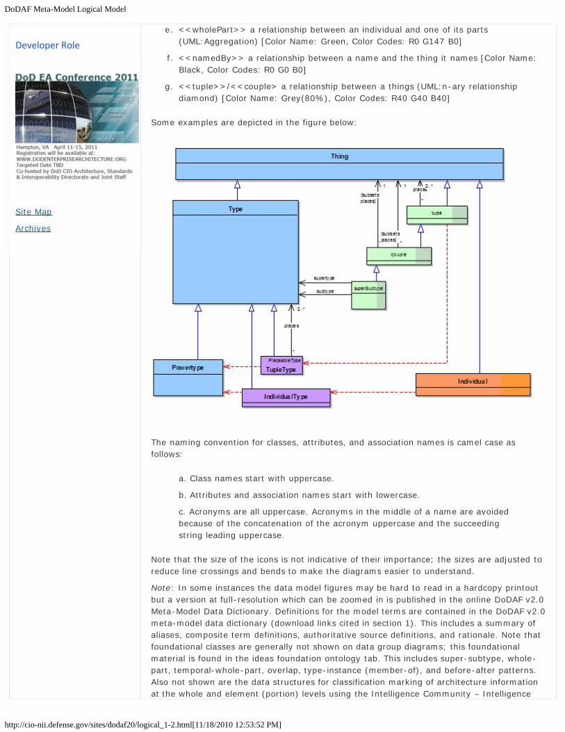
DoDAF Meta-Model Logical Model
http://cio-nii.defense.gov/sites/dodaf20/logical_1-2.html[11/18/2010 12:53:52 PM]
e. <<wholePart>> a relationship between an individual and one of its parts(UML:Aggregation) [Color Name: Green, Color Codes: R0 G147 B0]
f. <<namedBy>> a relationship between a name and the thing it names [Color Name:Black, Color Codes: R0 G0 B0]
g. <<tuple>>/<<couple> a relationship between a things (UML:n-ary relationshipdiamond) [Color Name: Grey(80%), Color Codes: R40 G40 B40]
Some examples are depicted in the figure below:
The naming convention for classes, attributes, and association names is camel case asfollows:
a. Class names start with uppercase.
b. Attributes and association names start with lowercase.
c. Acronyms are all uppercase. Acronyms in the middle of a name are avoidedbecause of the concatenation of the acronym uppercase and the succeedingstring leading uppercase.
Note that the size of the icons is not indicative of their importance; the sizes are adjusted toreduce line crossings and bends to make the diagrams easier to understand.
Note: In some instances the data model figures may be hard to read in a hardcopy printoutbut a version at full-resolution which can be zoomed in is published in the online DoDAF v2.0Meta-Model Data Dictionary. Definitions for the model terms are contained in the DoDAF v2.0meta-model data dictionary (download links cited in section 1). This includes a summary ofaliases, composite term definitions, authoritative source definitions, and rationale. Note thatfoundational classes are generally not shown on data group diagrams; this foundationalmaterial is found in the ideas foundation ontology tab. This includes super-subtype, whole-part, temporal-whole-part, overlap, type-instance (member-of), and before-after patterns.Also not shown are the data structures for classification marking of architecture informationat the whole and element (portion) levels using the Intelligence Community – Intelligence
Developer Role
Site Map
Archives

DoDAF Meta-Model Logical Model
http://cio-nii.defense.gov/sites/dodaf20/logical_1-2.html[11/18/2010 12:53:52 PM]
Standard Markings (IC-ISM). The schema for the IC-ISM is in physical exchangespecification (PES) tab. Lastly, note that the size of the icons is not indicative of theirimportance; sizes are adjusted to reduce line crossings and bends to make the diagramseasier to understand.
Go to top of page ?
Privacy Policy | Web Policy | Contact | Submit Change Requests

DoDAF Meta-Model Logical Model
http://cio-nii.defense.gov/sites/dodaf20/logical_1-3.html[11/18/2010 12:54:03 PM]
Home DoDAF-DM2 WG DoDAF Journal DoD Meta Data Registry IDEAS Links
How to Use the DODAF Meta Model (DM2)
Presentation Types for DM2 Data
Within the DoDAF Meta-model, the elements in the DoDAF Models (Views) are representedwith time periods (temporal extents). Temporal extent can connote the future, thus allowingthe models to represent “To-Be” capabilities and processes or the “before-after” aspects ofthe activities. Generally, DoDAF views, models and supporting data are represented in thefollowing general forms:
Structural Models comprised of diagrams describing the structural or static aspects ofarchitecture.Behavioral Models comprised of diagrams describing the behavioral or dynamicaspects of architecture.Tree Models-A type of structural model which can represent DoDAF elements in ataxonomic form.. These can represent “whole-part”, “super-subtype relationships orother relationships. These models are particularly important in maintaining traceabilitythru the various level of detail in representing the design or architecture. A WorkBreakdown Structure (WBS) is an example of a model including both activities and/orperformers in a decomposition tree.Mapping: Views that provide matrix (or similar) mappings between two different typesof information. This used to represent such things as functional and data allocationsand traceability.Tabular: Views which present data arranged in rows and columns, which generallyamplify or have a direct relationship to the behavioral, structural (includingontological) models.Pictorial: Views such as free-form pictures.Timeline: Model comprised of diagrams usually describing the programmatic aspectsof architecture ((E.g. Gant Chart). This is generally related directly to the WBStaxonomic model. These can also represent time in efficiency analysis of the activitiesin a process (e.g. LSS analysis).
Go to top of page ?
Introduction
What is New in DoDAF V2.0
Vision for DoDAF V2.0
Architecture Resources
DoDAF V1.5 Support
Relationships to otherFrameworks
Background
Architecture Development
Viewpoints
Models
DM2 - DoDAF Meta-Model
Conceptual
Logical
Performers
Resource Flows
Information and Data
Rules
Goals
Capability
Services
Project
Reification
Organizational Structure
Measures
Locations
Pedigree
PES
IDEAS FoundationOntology
Manager Role
Architect Role
Department of Defense

DoDAF Meta-Model Logical Model
http://cio-nii.defense.gov/sites/dodaf20/logical_1-3.html[11/18/2010 12:54:03 PM]
Developer Role
Site Map
Archives
Privacy Policy | Web Policy | Contact | Submit Change Requests

DM2 - Performers
http://cio-nii.defense.gov/sites/dodaf20/performers.html#top[11/18/2010 12:54:23 PM]
Home DoDAF-DM2 WG DoDAF Journal DoD Meta Data Registry IDEAS Links
DM2 Data Groups
Performers
Performer is a class of entities that are central to the description of architecture. It is theWho in the Architectural Development Process. The How, tasks, activities, and processes(composite of activities), are assigned to Performers to accomplish the desired outcome.Performers are further subdivided and allocated to organizations, personnel andmechanization. Rules, locations and measures are then applied to organizations, personneland mechanization. Within this assignment and allocation process there are many majortradeoff opportunities. Automation (mechanization versus people) tradeoffs, analysis foritems such as performance and cost/benefit are involved in the process. When thesetradeoffs and associated decisions are sufficiently mature, an allocated baseline can bedeclared and initial work breakdown structures refined.
Data Group Descriptions
The DoDAF Meta Model for the data comprising Performers, is shown in the figure below.
a. The first thing to note about Performer is that it can represent:1. A Person Type such as described by the Amy’s Military Occupational Specialties
(MOS). MOS describe Skills and their measurement (not shown in thisdiagram). Includes Materiel assigned and necessary for the performance ofactivities, e.g., as per Army CTA-50. Note that Person Types have temporalwhole-parts (states) such as in-garrison or deployed that may have differentMateriel compositions and other associations such as applicable Rules.
2. An Organization (type or actual Individual Organization) meaning a missionchartered organization, not limited to just collections of people or locations,e.g., the Federal Bureau of Investigation (FBI) has a chartered mission and itchooses the locations, people, etc., to accomplish such.
3. A System in the general sense of an assemblage of components – machine,human – that accomplish a function, i.e., anything from small pieces ofequipment to FoS and SoS. Note that Systems are made up of Materiel (e.g.,equipment, aircraft, and vessels) and Personnel Types, and organizationalelements.
4. A Service, from a software service to a business service such as Search andRescue.
5. Any combination of the above.
b. The performance of an Activity by a Performer occurs in physical space and time. Thatis, at some place and time, the Activity is conducted. This is referred to as a spatial-temporal overlap, simply meaning that the Activity and Performer overlap in spaceand time. There are two ways in which a Performer spatial-temporally overlaps anActivity:
1. In the act of performing the Activity. This relationship is sometimes calledassigned to for the purposes of traceability.
2. The other way is as part of a larger process (aggregated Activity). This issometimes called allocated to and forms the initial stages of system or processdecomposition. Allocated Performer elements (parts of Performers) are assignedActivities (or processes, tasks) in the initial stages of Performer definition.
DM2 - DoDAF Meta-Model
Conceptual
Logical
Performers
Resource Flows
Information and Data
Rules
Goals
Capability
Services
Project
Reification
Organizational Structure
Measures
Locations
Pedigree
PES
IDEAS FoundationOntology
Site Map
Department of Defense

DM2 - Performers
http://cio-nii.defense.gov/sites/dodaf20/performers.html#top[11/18/2010 12:54:23 PM]
c. A standard (Rule) constrains an Activity in general. Some of those constraints mightalso apply to the performance of the Activity by a Performer.
d. A Performer may have Measures associated with the performance of an Activity (e.g.,target tracking accuracy.) It may also have Measures associated with the Performeroverall (e.g., operational condition.)
e. Performers perform at Locations that can be specific positions or areas, regions, orinstallations, sites, or facilities. Location type requirements/capabilities of a Performerare captured/expressed via the Activities that are performed under certain Conditions(e.g., must be able to perform Maneuver under Desert Conditions.)
f. Activities performed by a System can be called system or service functions (i.e.,activities and/or processes performed by a system). System or service functions(activities) are allocated to hardware, software, firmware or personnel (when theperson is considered integral to the system).
g. In typical uses, the Activities are represented by verbs and Performers arerepresented by nouns. This distinguishes the how from the who. In a typicalspecification process allocation to performers can take place at varying levels of detaildepending on the design maturity or the intended degree of design constraint.
h. Performers are represented in many places and stages in the detailed architecture. Itshould be noted that a pure Requirements Architectural Description may not showallocations or performer. This may be left to later stages of the design process.Further, not all architecture modeling standards explicitly provide for allocation. Forexample, the Systems Modeling Language (SysML) extensions to the UML modelingstandard have added this feature.
DoDAF Meta Model for Performers(Click to enlarge)
Usage in Core Processes
Data for Performer are used in the following ways:

DM2 - Performers
http://cio-nii.defense.gov/sites/dodaf20/performers.html#top[11/18/2010 12:54:23 PM]
JCIDS:
1. Person Type processes are typically termed Tactics, Techniques and Procedures (TTP)in DoD. Procedures are allocated sets of activities and/or processes, where Tactics andTechniques, typically, are made up of the procedures as influenced by rules, doctrine,paradigms, etc. acquired through skill development during the education and trainingprocess.
2. A pure Requirements Architectural Description may not show allocations or performer.This may be left to later stages of the design process.
PPBE:
1. Programs of Record (PoR) are Projects that can contain both material and non-material Performers (See FYDP Program Structure Handbook (DoD 7045.7-H).
2. Program of Record are linked to the PPBE through the Work Breakdown Structure(WBS) (see DAS) depicting Performers related to cost.
3. The Planning and Programming*[1] process typically conducts analysis through theevaluation of Capabilities, Performers and the attributes associated with Performers(e.g. Measures). (e.g. “Gap and Overlap analysis”, Capability evolution, etc.).
DAS:
1. MIL-HDBK-881A*[2] and DoD 5000.1, in providing fundamental guidance forspecifications, WBS, Statement of Works (SOWs) of the DAS, all require theidentification of the Performers and their component parts and types as fundamentalelements.
2. The acquisition process generally involves Performers either through the materialacquisition of systems or the acquisition of processes associated with performers.
3. The acquisition process can also involve the Acquisition of Services.
SE:
1. Activities are assigned to Performers (organizational, human, materiel, or somecombination thereof). Capabilities or lower-level derived capabilities,measures,conditions, constraints and other expressions of requirements are assignedto the various levels of Performer reification. Allocation occurs from level-to-level aspart of structural design decomposition or design refinement.
2. Allocation is the term used by architects and engineers to denote the organized cross-association (mapping) of elements within the various structures or hierarchies of auser view regardless of modeling convention or standard. The concept of allocationrequires flexibility suitable for abstract system specification, rather than a particularconstrained method of system or software design. System modelers often associatevarious elements in abstract, preliminary, and sometimes tentative ways. Allocationscan be used early in the design as a precursor to more detailed rigorous specificationsand implementations. As the requirements definition stage gives way to the designstage and actual components become visible, it becomes important to distinguishbetween allocated to and assigned to.
3. Some types of performers under configuration control called system ConfigurationItems (CIs). Software Configuration items are termed Computer SoftwareConfiguration Items (CSCIs) or Software Configuration items (SCIs) in MIL-HDBK-881A. Hardware Configuration items may follow the Mil-STD-196E taxonomy (Central,Center, System, Subsystem, Set, Group, Unit.) MIL-HDBK-881A , which guides DoDWork Breakdown Structures (WBS), defines software only by levels (e.g., 1, 2, 3, etc.)

DM2 - Performers
http://cio-nii.defense.gov/sites/dodaf20/performers.html#top[11/18/2010 12:54:23 PM]
Ops Planning:
1. Determines who is going to accomplish the required tasks (activities), where, underwhat conditions, and to what measures
CPM:
1. Performers are the major items in the portfolio to be managed and optimized
Go to top of page ?
Privacy Policy | Web Policy | Contact | Submit Change Requests

DM2 - Resource Flows
http://cio-nii.defense.gov/sites/dodaf20/resource_flows.html[11/18/2010 12:54:43 PM]
Home DoDAF-DM2 WG DoDAF Journal DoD Meta Data Registry IDEAS Links
DM2 - DoDAF Meta-Model
Resource Flows
Resource Flows are used to model the flow of Resources – Materiel, Information (and Data),Geo-Spatial Extents, Performers, or any combination thereof. Resource Flows are keymodeling techniques used in the definition of Interfaces and assurance of Interoperabilitybetween Activities and their associated Performers (e.g., Systems and Personnel.) ResourceFlow models and associated analysis techniques reveal behavior such as:
The connectivity between resources. Resource Flow modeling provides an explicit means to describe the behavior ofactivities, systems, organizations and their composite effects on the overall enterprise.The content of the information flowing between resources (e.g., interface definition).The order or sequential behavior (parallel or serial) of the resources in relation to oneanother (e.g., project task execution and critical path). The behavior of Resource Flow between or within organizations (e.g., work flow,information flow, etc.).The changes in state during the spatial and/or temporal existence of the resource.The rules that modify the behavior of the Resource Flow (e.g., business rules,controls, decisions, etc.).The measures that define the quality, constraints, timing, etc. of the Resource Flow(e.g., Quality of Service (QoS), measures of performance, measures of effectiveness,etc.).The flow of control orchestrating the behavior of the Resource Flow.
Data Group Description
The DoDAF Meta Model for the data comprising Resource Flows is shown in the figure below.The following should be noted:
a. Whereas prior versions of DoDAF modeled only information and data exchanges andflows, this version also allows modeling of other flows, such as:
1. Materiel flows such as ammunition, fuel, etc. important for modeling the firerate, logistics, etc., aspects of a Capability solution so it can be compared withother alternative solutions.
2. Personnel Types such as Military Occupational Specialty (MOS) that allowrepresentation of the Training and Education pipeline aspects of Doctrine,Organization, Training, Material, Leadership and Education, Personnel, andFacilities (DOTMLPF).
3. Performers such as Services, Systems, or Organizations that might be theoutput or result of a Project’s design and production process (activities). Thisallows modeling of, for instance, an acquisition project.
b. Another difference from prior versions of DoDAF is that all exchanges and flows are byvirtue of a producing or consuming Activity. Resource Flows are Activity-based, notPerformer based since a Performer cannot produce or consume a resource other thanby conduct of a production or consumption activity. That is, a Performer can onlyprovide or consume by conducting an activity of production or consumption. Forinstance, publication and subscription are modeled as an interaction between thepublishing Activity, the subscribing Activity, and the information or data Resource.
DM2 - DoDAF Meta-Model
Conceptual
Logical
Performers
Resource Flows
Information and Data
Rules
Goals
Capability
Services
Project
Reification
Organizational Structure
Measures
Locations
Pedigree
PES
IDEAS FoundationOntology
Site Map
Department of Defense

DM2 - Resource Flows
http://cio-nii.defense.gov/sites/dodaf20/resource_flows.html[11/18/2010 12:54:43 PM]
Note that publication is typically not at the same time as subscription but thesubscriber does have to go to the publication place to retrieve the Resource. Forexample, data might be published at 2:00 GMT on a server located at some URL andthe subscriber may not overlap until 10:00 GMT. Also note in the diagram the overlapis a triple – the producing Activity, the Consuming Activity, and the Resource.
c. The exchange or flow triple may have standards (Rules) associated with it such asInformation Assurance (IA)/Security rules or, for data publication or subscription, dataCOI and web services standards.
d. Rules and Measures are applied to specific Activities and their Performers. Activities,Systems and Personnel can be assigned to Locations and further can be assignedConditions and Constraints.
e. The term flow implies that something (e.g., materiel, information) is moving frompoint A to point B, hence the use of the foundation concept of “overlap”.
f. The exchange or flow triple may have Measures associated with it such as timeliness,throughput, reliability, or QoS.
g. Resource Flow modeling can be performed at varying levels of detail and fidelitydepending on the areas of concern being analyzed and the solutions being sought. Theupper-level aggregations have been termed need lines in previous versions DoDAF.Other terminology expressing levels of aggregation are used depending on thecommunity of interest (e.g., The SysML modeling standard uses lifeline).
h. It should be noted that information inputs and outputs between resources for somelevels of decomposition may be at a higher-level of abstraction than the informationcharacteristics represented in the matrix. This is commonly done to simplify graphicalrepresentations of information flow or in the initial definition stages where thecharacteristics are still unknown. In this case, multiple information exchanges will mapto a single resource input or output. Similarly, the information inputs and outputsbetween resources at a low-level of decomposition may be at a higher-level of detailthan the information exchanges in the matrix, and multiple information inputs andoutputs may map to a single information exchange. In these cases, to provide thenecessary clarity and precision, an ontological or taxonomic structure of informationaggregation should be developed for use in each level of decomposition of theResource Flow models (e.g., The Navy Common Information Exchange List [CIEL]represents initiatives showing taxonomic structure or levels of aggregation).
DoDAF Meta Model for Resource Flow

DM2 - Resource Flows
http://cio-nii.defense.gov/sites/dodaf20/resource_flows.html[11/18/2010 12:54:43 PM]
(Click to enlarge)
Usage in Core Processes
Resource Flow modeling is a fundamental engineering based technique used in InformationTechnology (IT) Architecture, System Engineering, Process Re-engineering, ResourcePlanning and many other disciplines.
a. JCIDS1. Where are the process bottlenecks?2. Are the activities and procedures interoperable?3. Identify new and emerging systems interoperability requirements.4. Uncover unnecessary or inefficient operational activities and information flows.5. Evaluate alternative architectures with different connectivity and Resource Flow
to maximize capability and minimize automation complexity.6. Identify critical connectivity needs and interfaces (or Key Interface Profiles
(KIPs) between activities and their performers (organizations and personneltypes).
7. Critical Interfaces are generally documented in formal interface documentationsigned by the responsible authorities (both information supplier and informationconsumer) in charge of each end of the interface. This type of interface may beannotated as a Key Interface (KI). A KI is defined as an interface where one ormore of the following criteria are met:
8. Support Analysis of Alternatives (AoA) and other Systems Engineering Analysis.b. DAS
1. The interface spans organizational boundaries (may be across instances of thesame system, but utilized by different organizations).
2. Support the development of test sequences and procedures.3. The Details of Resource Flow (materiel, personnel, or data) are generally
documented in Interface Control Documents (ICDs), Interface RequirementsSpecifications (IRSs) and Interface Description Documents (IDDs). This data istypically provided to DoD Investment Review Board (IRB) registry systems forthe purpose of milestone reviews and support of acquisition decisions points.
c. PPBE1. Ensure FYDP provides flows needed for operations and missions2. Ensure consumption requirements are met by producers
d. SE1. Identify new system or service, functions (activities), components and
modifications required.2. Identify new Resource Flow and system integration requirements.3. Identification of the need for Application of new standards.4. Clearly identify the relationship and information flow between systems and
system/services in an SoS or between services in a Service OrientedArchitecture (SOA) including definition of publish or subscribe requirements
5. Interface Identification and Definition including interoperability analysis andstandardization.
6. Support configuration management of interfaces. Interfaces are generallydocumented in interface documentation representing the agreements of theresponsible parties in charge of each end of the interface (both informationsupplier and information consumer). This, in no way implies a point-to-pointinterface. Interfaces implemented with an enterprise service bus, for example,are defined with appropriate publish/subscribe documentation formalized, ifnecessary, with contractual agreements between information supplier andconsumer.
7. Critical interfaces are generally documented in formal interface documentation

DM2 - Resource Flows
http://cio-nii.defense.gov/sites/dodaf20/resource_flows.html[11/18/2010 12:54:43 PM]
signed by the responsible authorities (both information supplier and informationconsumer) in charge of each end of the interface. For legacy point-to-pointinterfaces this may be in the form of Interface Control Drawings (ICDs),Interface Requirement Documents (IRSs), Interface Design Documents (IDDs),etc. In multiple access or common connectivity (radio communications or bustype connectivity) implementations may be in the form of formal agreements(defined herein as a consent among parties regarding the terms and conditionsof activities that said parties participate in) detailing the specific set ofimplementations (e.g., Tactical Digital Information Links [TADILs]) dataelements implementation tables or in the case of a SOA, a publish/subscribeimplementation document. These agreements are, in general, managed andcontrolled by the SoS or System Project manager. In new systems, and wherepossible the interface should be managed and configuration controlled using acommon precision data model. Figure 4 illustrates the evolution fromconfiguration control of legacy point-to-point interfaces to a net-centric,distributed processing means of connectivity using carefully managed publishand subscribe agreements and documentation based on formally documentedlogical and physical data models.
Migrating from Legacy to Data Focused Configuration Management(Click to enlarge)
e. Ops Planning1. Operations utilizing information flows should be technology independent.
However, operations and their relationships may be influenced by newtechnologies. There may be some cases in which it is necessary to documentthe way activities are performed to examine ways in which new systems couldfacilitate streamlining the activities
2. Mission Planning including simulation and training.3. Logistics planning.4. Provide a necessary foundation for depicting information needs and task
sequencing to assist in producing procedures, operational plans and facilitateassociated personnel training.
5. Identify critical mission threads and operational Resource Flow exchanges byannotating which activities are critical (i.e., identify the activities in the DoDAF-

DM2 - Resource Flows
http://cio-nii.defense.gov/sites/dodaf20/resource_flows.html[11/18/2010 12:54:43 PM]
described Model that are critical e.g., Critical Path).f. CPM
1. Resource flows can be used to represent the structural and behavioralrelationships between the Activities and Performers within the portfolioincluding interfaces and interdependencies.
Presentation
Resource Flows are generally depicted as Structural, Behavioral and Tree models withamplifying tabular information. A generic Resource Flow presentation is shown in the figurebelow.
Migrating from Legacy to Data Focused Configuration Management
Go to top of page ?
Privacy Policy | Web Policy | Contact | Submit Change Requests

DM2 - Information and Data
http://cio-nii.defense.gov/sites/dodaf20/info_data.html[11/18/2010 1:26:23 PM]
Home DoDAF-DM2 WG DoDAF Journal DoD Meta Data Registry IDEAS Links
DM2 Data Groups
Information and Data
Information is the state of a something-of-interest that is materialized, in any medium orform, and communicated or received. In DoDAF V1.0, this took the form of what was calleda logical data model which even in DoDAF V1.0 permitted a less structured and formalizeddescription than the computer science definition of a logical data model. In DoDAF V2.0, theemphasis is on the identification and description of the information in a semantic form (whatit means) and why it is of interest (who uses it). Although this may entail some formalitysuch as describing relationships between concepts, its purpose is to convey the interests inthe operator, executive, or business person’s frame of reference.
Data is the representation of information in a formalized manner suitable for communication,interpretation, or processing by humans or by automatic means, and is concerned with theencoding of information for repeatability, meaning, and proceduralized use. Whileinformation descriptions are useful in understanding requirements, e.g., inter-federateinformation sharing requirements or intra-federate representation strategies, datadescriptions are important in responsive implementations of those requirements andassurances of interoperable data sharing within and between federates.
Data Group Description
The DoDAF Meta Model, for the data comprising Information and Data, is shown in the figurebelow.
Information and Data Model Diagram(Click image to enlarge)
Items of note are as follows:
DM2 - DoDAF Meta-Model
Conceptual
Logical
Performers
Resource Flows
Information and Data
Rules
Goals
Capability
Services
Project
Reification
Organizational Structure
Measures
Locations
Pedigree
PES
IDEAS FoundationOntology
Site Map
Department of Defense
DM2 - Information and Data
http://cio-nii.defense.gov/sites/dodaf20/info_data.html[11/18/2010 1:26:23 PM]
a. The key concept in this model is that Information describes some Thing – material,temporal, or even abstract, such as a relationship (Tuple) or set (Type).
b. Since Information is a Thing, Information can describe other Information, e.g.,metadata.
c. A Name is a type of Information in that it describes a Thing. A Name may be short orlong – there is no restriction. So a textual description can be thought of a just a longName. Information is more general than text strings and could be structured,formalized, or include other manners of description such as diagrams or images.
d. Information, as a Resource Type, inherits whole-part, super-subtype, and before-after relationships.
e. If Information is processable by humans or machines in a repeatable way, it is calledproceduralized. Not all proceduralized information is necessarily computerized; formsare examples of data proceduralized for human repeatable processing.
f. Data to be proceduralized has associations such as parts and types as well as otherapplication specific associations. So for an Entity-Relationship model, Attributes arehas associations with Entities and Entities are related according to verb phrases andcardinalities. In the physical schema, the fields are associated to data types.
g. The representation for Data is not intended to cover all the details of, for instance, arelational data base management system (DBMS) underlying Meta-model, but justthose aspects necessary to support the decision-making of the core processes.
h. Architectural Descriptions describes architectures. An Activity Model is an example ofan Architectural Description. Two subtypes of Architectural Description are called out –the AV-1 and the Manifest – because of their importance in discovery and exchange,respectively. Note that the AV-1 information can also be provided in a structuredmanner, using the Project data group to describe the architecture project’s goals,timeline, activities, resources, productions, rules, measures, etc. In a typicaldevelopment project, the architecture descriptions will be at increasing levels of detail,what John Zachman calls “levels of reification”.
It should be noted that all methods, even the most philosophical and methodical, involve theingestion of some record of the enterprise’s processes, legacy information-keeping systems,and descriptions of what types of things it thinks it deals with. Upon collection of this rawdata, terms within it are then:
a. Identified. This is done by noting recurring or key terms.b. Understood. Definitions of terms are sought and researched. In most cases, there are
multiple authoritative definitions. Definitions selected should be appropriate for thecontext of use of the term within the enterprise activities.
c. Collated and correlated. This is done by grouping seemingly similar or related terms.d. Harmonized. In this step, aliases, near-aliases, and composite terms are identified. A
consensus definition is formulated from the authoritative source definitions. Oftensuper-subtype and whole-part relationships begin to emerge.
The next step is to relate the harmonized terms. Some of the relationships are implicit in thedefinitions and these definitions may contribute to the relationship description. At this point,the formality can vary. A formal ontological approach will type all relationships tofoundational concepts such as whole-part and super-subtype. However, there are manymetaphysical challenges with such an approach and it is not necessary for manyapplications. This constitutes the conceptual-level of modeling, defined and related terms,now considered concepts because the definitions and relationships lend a meaning to theterms. The conceptual model should be understandable by anyone knowledgeable about theenterprise. Super-subtype and whole-part relationships can provide cognitive economy.Conceptual models can be done in Entity-Relationship or UML Class model style although anyformat that documents definitions and relationships is functionally equivalent. Note that thesubtype concept in UML generally results in the subclass inheriting properties from thesupertype while in Entity-Relationship (E-R) modeling only the identifying keys are inheriteddirectly; the other supertype properties are available after a join operation.
DM2 - Information and Data
http://cio-nii.defense.gov/sites/dodaf20/info_data.html[11/18/2010 1:26:23 PM]
At the logical-level, relationships may have cardinalities or other rules added that indicatehow many of one instance of something relates to an instance of something else, thenecessity of such relations, and so on. The concepts may also be attributed, meaning theywill be said to have some other concept, e.g., the concept of eye has the concept of color.Often at the logical-level, the relationships are reified or made concrete or explicit. At thelogical-level, this is done in case there is something additional that needs to be stated aboutthe relationship, e.g., the quantity of some part of something or the classification of therelated information, which may be different from the classification of the individual elements.There may also be considerations of normalization, meaning that the database structure ismodified for general-purpose querying and is free of certain undesirable characteristicsduring insertion, update, and deletion operations that could lead to a loss of data integrity.The benefits of normalization are to uncover additional business rules that might have beenoverlooked without the analytical rigor of normalization and ensure the precise capture ofbusiness logic. The logical model, though having more parts than the conceptual model,should still be understandable by enterprise experts. At the logical-level, some sort ofmodeling style is normally used such as Entity-Relationship or UML Class modeling.
At the physical-level, the exact means by which the information is to be exchanged, stored,and processed is determined. At this level, we are talking about data. The efficiency,reliability, and assured repeatability of the data use are considered. The datatypes, the exactformat in which the data is stored are determined. The datatype needs to accommodate allthe data that is permissible to store or exchange yet be efficient and disallow formats thatare not permissible. The entities may be de-normalized for efficiency so that join operationsdon’t have to be performed. Logical associations may be replaced with identifiers (e.g., asassociative entities or foreign or migrated keys in Entity Relationship Diagrams [ERDs] orexplicit identifier attributes or association classes in class models). Keys, identifiers, andother means of lookup are setup. Indexes, hashes, and other mechanisms may be setup toallow data access in accordance with requirements. The physical target may be any of thefollowing:
a. Database – relational, object, or flat file.b. Message exchange format – document (e.g., XML), binary (e.g., Interface Definition
Language (IDL)).c. Cybernetic (human – machine), e.g., print or screen formats, such as forms.
Usage in Core Processes
Information and Data models are used in the following ways:
a. Commonality and Interoperability between Core processes1. Information models materialize for enterprise participants what things areimportant to the enterprise and how they are related.2. Information models can serve as a basis for standardization of terminology andconcept inter-relationships for human, machine, and human-machinecommunications.3. Information models can provide cognitive compactness for an enterprise’spersonnel through the use of taxonomies and other relationship structures. This canimprove clarity, efficiency, accuracy, and interoperability of action within theenterprise.4. Information models document the scope of things the enterprise is concerned within a form that allows comparison with other communities of interest to reveal commoninterests.5. COI coordination and harmonization.6. Authoritative sources identification and management.
b. JCIDS and PPBE1) Data and information models can be used to determine if a proposed capability willinteroperate, be redundant with, or fill gaps in conjunction with other capabilities.
c. SE and DAS

DM2 - Information and Data
http://cio-nii.defense.gov/sites/dodaf20/info_data.html[11/18/2010 1:26:23 PM]
1) Data models can be used to generate persistent storage of information such as indatabases. 2) Data models can be used to generate formats for exchanging data betweenmachines, humans, and machine-to-human. For example, an XSD is a physical datamodel that is generally an exchange format. Web services can be used with relationalDBMS' to generate XML for exchange in the format of the data model implemented inthe DBMS. The underlying data models (the physical data model and the exchangedata format) do not have to be the same; a translator or mediator may be invoked totranslate during the exchange. 3) Data models can be used to compare whether Performers are compatible for dataexchange. 4) Interdependent data or information needs. 5) Data and information models can be used during milestone reviews to verifyinteroperability, non-redundancy, and sufficiency of the solution. 6) Information models are useful in initial discovery of a service, to know what sortsof information it may provide access to or its accessed capabilities need. Aninformation model is part of a service description. 7) Data models are useful in knowing how to interact with a service and thecapabilities it provides and for establishing the service contract. A data model is partof a service description and service contract. 8) Database/sources consolidation and migration. 9) Standards definition and establishment. 10) Mediation and cross-COI sharing.
d. OPS Planninge. CPM
1) Data and information models can be used to determine if components of a portfoliohave: 2) Overlapping data or information production (an indication of potential unwantedredundancy). 3) Data assets management.
Presentation
Presentation of Information and Data are depicted using all the forms shown in 1.3 andmanifest themselves in the presentation of many of the other Data Groups. Modelinginformation and data have well established techniques and styles. Techniques forconstructing and presenting models of Information and Data vary. They are taught inacademic and vocational curricula. There is considerable literature, such as books,professional journals, conference proceedings, and professional magazines, on best practices,experiences, and theory. The figure below illustrates some of the basic methods for modelcreation.
Examples of the Ways Information and Data Models are Constructed

DM2 - Information and Data
http://cio-nii.defense.gov/sites/dodaf20/info_data.html[11/18/2010 1:26:23 PM]
Go to top of page ?
Privacy Policy | Web Policy | Contact | Submit Change Requests

DM2 - Rules
http://cio-nii.defense.gov/sites/dodaf20/rules.html[11/18/2010 1:28:03 PM]
Home DoDAF-DM2 WG DoDAF Journal DoD Meta Data Registry IDEAS Links
DM2 - DoDAF Meta-Model
Rules
Rules are prescriptive sets of procedures regarding the execution of activities within anenterprise. Rules exist within the enterprise whether or not they are ever written down,talked about, or even part of an organization’s consciousness. However, it is fairly commonpractice for organizations to gather rules in a formal manner for specific purposes.
Business rules are a type of Rule that govern actions and are initially discovered as part of aformal requirement-gathering process during the initial stages of a Project or during activityanalysis, or event analysis. In this case, the collecting of the business rules is coincidental tothe larger discovery process of determining the workflow of a process. Projects such as thelaunching of a new system or service that supports a new or changed business operationmight lead to a new body of business rules for an organization that would require employeesto conceptualize the purpose of the organization in a new way. This practice of coincidentalbusiness rule gathering is vulnerable to the creation of inconsistent or even conflictingbusiness rules within different organizational units, or within the same organizational unitover time.
The DoDAF Meta Model provides a set of clear, concise data about rules that facilitates thecreation of rules and enables the sharing of those rules with others requiring similarinformation.
A rule is not a process - the two, while related, are very different. A process is atransformation that produces new things (outputs) from existing things (inputs), while a ruleprescribes the exact procedures to be used to ensure that the output is as to be expected ineach instance that the process is executed.
Data Group Description
The DoDAF Meta Model for the data comprising Rules is shown in the figure below.
DM2 - DoDAF Meta-Model
Conceptual
Logical
Performers
Resource Flows
Information and Data
Rules
Goals
Capability
Services
Project
Reification
Organizational Structure
Measures
Locations
Pedigree
PES
IDEAS FoundationOntology
Site Map
Department of Defense

DM2 - Rules
http://cio-nii.defense.gov/sites/dodaf20/rules.html[11/18/2010 1:28:03 PM]
DoDAF Meta Model for Rules(Click image to enlarge)
The following should be noted about the Rules Data Group:
a. A Rule constrains Activities. For example, a speed limit rule constrains driving activity.Some seemingly static rules have the effect of limiting possible activities. Forexample, a rule that security fences must be 10 feet high constrains the activity ofbuilding security fences. This constraint may apply or vary under certain conditions.For example, speed limits can be lower in poor weather conditions.
b. Security classification, security marking, releasability, etc. are types of Guidance.Similarly; a Rule is a stronger form of Guidance.
c. An important Constraint type is a Service Policy that constrains access to capabilityPerformers.
d. Doctrine, by definition, constrains military action.
Usage in Core Processes
Rules data are used to create, document, and share rules of all types that supportoperational activities and/or the execution of capabilities in operational processes (compositeactivities). These data can include:
a. Processes that define transactions where data must be exchanged or passed toexecute a specified activity, such as PPBE, CPM, JCIDS, or DAS.
b. Rules that define methods of accessing information or services within the net-centricenvironment, such as Ops, PPBE, CPM, or JCIDS.

DM2 - Rules
http://cio-nii.defense.gov/sites/dodaf20/rules.html[11/18/2010 1:28:03 PM]
c. The order of steps that occur in a series of actions that must be performed in aspecific order, such as DAS, SE, PPBE, or CPM.
d. Rules defining analysis of options or future actions, such as Ops Planning, JCIDS, PPBEor CPM.
Data for Rules are used in the six core processes in the following ways:
a. JCIDS:1) For Materiel Facility, Installation, and Site trade-offs as part of DOTMLPF analyses2) For detailing Interoperability requirements. 3) In constraining requirements dealing with material and non-material solutions.4) In relating Doctrine and TT&P to material and non-material solutions.
b. PPBE: 1) In the Planning and Programming process many rules are applied to cost-benefittradeoffs, cost estimation, program structure, and program constraints.
c. DAS: 1) In both technical and programmatic aspects of the DAS. 2) In specification, standards, directives and guidelines.
d. SE:1) In the architectural descriptions of systems describing both structure and behavior.
2) In standards applied throughout the design and development process.e. Ops Planning:
1) Rules are the basic elements contained in Doctrine, TT&P and training publications.Rules are used throughout the development and architectural descriptions ofOperational processes.
f. CPM:1) In describing and governing both the programmatic and technical aspects of theportfolio.2) In describing the standards and constraints applicable to the portfolio.
Presentation
Rules can be represented in many ways. Typically behavioral and tree structures as well asvarious logic mapping techniques can be used to depict rules, their relationships andinteractions. Conflicting rules can be identified using many well know logic analysisinstruments and techniques.
Go to top of page ?
Privacy Policy | Web Policy | Contact | Submit Change Requests

DM2 - Goals
http://cio-nii.defense.gov/sites/dodaf20/goals.html[11/18/2010 1:32:57 PM]
Home DoDAF-DM2 WG DoDAF Journal DoD Meta Data Registry IDEAS Links
DM2 Data Group
Goals
Goals data are defined to represent the desired effect, ends, visions, outcomes, objectives,etc. for which operational processes, projects, or special programs are conducted. Goals areused to help guide the Organizations to ensure that everyday operations are aligned to astrategic direction. A goal is an end toward which long-term, ongoing effort is directed. Ingeneral, goals are established to provide a description of the intended future state. They areestablished to provide a target to aim toward, whereby activity is focused on attaining thedesired effect (goal). Goals provide participants in activities a sense of direction, and a viewof what to expect as activity progresses toward some end point. A Goal (and its aliases)describe a desired state of a Resource (Materiel, Information, Performer, or GeopoliticalExtent.) Goals data can be expressed as enterprise goals—high-level strategic goals thatapply to the entire organization—or as more specific operational goals that define desiredoutcomes of the work process.
Data Group Description
The following should be noted about the Goals Data Group:
a. Although the language sounds different, the meaning of a desired effect (a change instate of some object) is the same as the meaning of goal.
b. A desired change in the state of some object leads to activities constrained by Rulesthat are performed by Performers. Some Activities are considered Events becausethey are of near-zero duration with respect to the frame of discernment of the Vision,Performers, etc.
c. Within DoDAF, goals are identified and described to provide direction to Activities andto orient those Activities toward a desired effect. When a Performer executes anActivity, the Performer does so within the limitations prescribed for the Activity(Rules) and aims toward a desired effect. That effect should either meet, or contributeto meeting, established Goals that reflect the vision of the organization.
Usage in Core Processes
Goals are established at all levels of the organization and each of the core DoD processes.Goals can be applied to the Enterprise or Solution architecture effort. Goals are particularlyuseful to teams undertaking an architecture development effort to evaluate the success ofthe effort and how the effort contributes to achieving higher level goals, missionrequirements, capability developments, or development of Services and Systems to supportDepartment or organizational business operations.
Data for Goals are useful for:
a. Scoping an activity to ensure that resources utilized in executing an activity contributeto the overall goals and vision of the organization.
b. Establishing rules under which activities are executed to create boundaries forefficiency and effectiveness (Constraints) and establishing those circumstances underwhich an activity is executed (Event).
c. Establishing measures to determine the success of an activity, consistent with anestablished goal.
DM2 - DoDAF Meta-Model
Conceptual
Logical
Performers
Resource Flows
Information and Data
Rules
Goals
Capability
Services
Project
Reification
Organizational Structure
Measures
Locations
Pedigree
PES
IDEAS FoundationOntology
Site Map
Department of Defense

DM2 - Goals
http://cio-nii.defense.gov/sites/dodaf20/goals.html[11/18/2010 1:32:57 PM]
Data for Projects can be used in the six core processes in the following ways:
a. JCIDS: In establishing desired and threshold capabilities. Traceability should always bemaintained between Goals and capabilities. This should include measures, rules andpedigree.
b. PPBE, DAS, SE: Goals are established at all level of the design, development andacquisition process. Traceability throughout the various levels is essential to theproper management an control of cost, systems engineering and acquisition.
c. Ops Planning: In establishing Operational Plans Goals and objectives are establishedrelated to Missions. Goals can be described as both strategic and tactical.
d. CPM: In establishing both the technical and programmatic aspects of the portfolio.
Presentation
Goals are typically depicted in tabular or textual form. It is desirable that Goals be presentedin a structured manner showing primary and derived goals. This enhances projecttraceability.
Go to top of page ?
Privacy Policy | Web Policy | Contact | Submit Change Requests

DM2 - Capability
http://cio-nii.defense.gov/sites/dodaf20/capability_mm.html[11/18/2010 1:34:03 PM]
Home DoDAF-DM2 WG DoDAF Journal DoD Meta Data Registry IDEAS Links
DM2 Data Groups
Capability
The Capability Data Group provides information on the collection and integration of activitiesthat combine to respond to a specific requirement. A capability, as defined here is “theability to achieve a desired effect under specified standards and conditions throughcombinations of means and ways to perform a set of tasks.” This definition is consistent withthat contained in the JCIDS Instruction published by the Joint Staff.
Data Group Description
The DoDAF Meta Model for the data comprising Capability is shown in the figure below. Itemsof note:
a. Ways and means are interpreted in DM2 language to be Resources and Activitiesb. Because a Desired Effect is a desired state of a Resource (see Goals data group), a
Capability is about states (persistence of current ones, or changes to future ones) ofResources.
c. Capabilities link to Measures (Metrics) through the Activities they entail and theDesired Effects sought.
d. Capabilities relate to Services via the realization of the Capability by a Performer thatis a Service. In general, a Service would not provide the Desired Effect(s) but, rather,access to ways and means (Activities and Resources) that would.
DoDAF Meta Model for Capability
DM2 - DoDAF Meta-Model
Conceptual
Logical
Performers
Resource Flows
Information and Data
Rules
Goals
Capability
Services
Project
Reification
Organizational Structure
Measures
Locations
Pedigree
PES
IDEAS FoundationOntology
Site Map
Department of Defense

DM2 - Capability
http://cio-nii.defense.gov/sites/dodaf20/capability_mm.html[11/18/2010 1:34:03 PM]
(Click image to enlarge)
Usage in Core Processes
Data for Capabilities are used to describe the capability; define acquisition and developmentrequirements necessary to provide the required capability; facilitate understanding ofcapability execution; develop/update/improve doctrine and educational materials in supportof capability execution; and to facilitate sharing and reuse of data.
The Capabilities Data Group (CDG) has a representation at varying levels, from enterpriselevel to solutions and applies to all DoD core processes. This includes enterprise goalsassociated with the overall vision, that provide a strategic context for the capabilitiesdescribed by an architecture, and an accompanying high-level scope, more general than thescenario-based scope defined in an operational concept diagram. At this level, the CDGenables a high-level description of capabilities in decision-makers contexts that can be usedfor communicating a strategic vision regarding capability evolution. Factors considered in aCapability Based Analysis are:
a. Doctrineb. Organizationsc. Trainingd. Materiele. Leadership and Educationf. Personnelg. Facilities
The following sections document how the Capability Data Group and DM2 support analysis ofeach of these factors.
In Joint Pub 1-02, Dictionary of Military and Associated Terms, doctrine is defined as“Fundamental principles by which the military forces or elements thereof guide their actionsin support of national objectives. It is authoritative but requires judgment in application.”
The concept of judgment required in application deals with decision making and cannot beprecisely modeled except perhaps as rules affecting the applicability of other rules. The partsof doctrine that can be modeled are included in the capability data group as follows:
a. Principles are modeled as Rules.
b. Military forces and elements thereof are modeled as types and assemblies ofPerformers.
c. Actions are modeled as Activities.
Thus, doctrine is contained in the specification of certain fundamental Rules, Activities, andPerformers and the relationships among them. These relationships are:
a. Each Performer must be of one or more Activities.
b. Each Activity must be by one or more Performers.
c. Each Rule may be a constraint on one or more Activities.
d. Each Activity may be constrained by one or more Rules.
e. Each Rule may be a constraint on one or more Performers.
f. Each Performer may be constrained by one or more Rules.
Thus, since the DM2 contains the entities and relationships listed above it contains thenecessary and sufficient set of entities and relationships to permit the modeling of doctrineand a separate data group for Doctrine is not required.
Organization. An organization is a specific real-world assemblage of people and other
DM2 - Capability
http://cio-nii.defense.gov/sites/dodaf20/capability_mm.html[11/18/2010 1:34:03 PM]
resources organized for an ongoing purpose. DM2 models Organizations as a type ofPerformer.
Defining an Organization as an assemblage means that each Organization exhibits awhole/part relationship whereby each Organization may be an assembly of otherOrganizations and each Organization may also be a component of one or more otherOrganizations. The following DM2 relationships are involved in the capability based analysisof Organization where each Organization is a type of Performer:
a. Each Capability must be the result of one or more Activities.
b. Each Activity must be by one or more Performers, where each Performermust be a type of Organization, therefore, each Capability must be provided byone or more Organizations.
c. Each Organization must be the Performer of one or more Activities.
d. Each Rule may be a constraint on one or more Organizations.
e. Each Organization may be constrained by one or more Rules.
f. Each Rule may be a constraint on one or more Activities.
g. Each Activity may be constrained by one or more Rules.
Training is defined as an activity or set of Activities to increase the capacity of one or moreperformers to perform one or more tasks under specified conditions to specific standards:
a. Each Performer may be either an Organization or a Person.
b. Each Performer must be of one or more Activities.
c. Each Activity must be performed under one or more Conditions.
d. Each Activity must be completed to meet one or more Standards.
e. Each Standard must be specified by one or more Measures.
Materiel is a type of Resource. Like Organization above, each Materiel exhibits a whole/partrelationship whereby each Materiel may be an assembly of other Materiels and each Materielmay also be a component of one or more other Materiels.
The following DM2 relationships are involved in the capability based analysis of materielwhere each Materiel is a part of a Performer:
a. Each Performer must be assigned to one or more Organizations.
b. Each Performer must be used by one or more Persons, where each Personmust be the member of only one Organization at any one time.
c. Each Capability must be the result of one or more Activities.
d. Each Activity must be by one or more Performers, where each Performermust be either an Organization or a Person using a Performer.
e. Each Performer must be the Performer of one or more Activities.
f. Each Rule may be a constraint on one or more Performers.
g. Each Performer may be constrained by one or more Rules.
h. Each Rule may be a constraint on one or more Activities.
i. Each Activity may be constrained by one or more Rules
Leadership and Education. Joint Pub 1-02 does not define leadership. In the context ofthe DM2, leadership is defined as the ability to lead. Joint Pub 1-02 defines MilitaryEducation as the systematic instruction of individuals in subjects that will enhance their

DM2 - Capability
http://cio-nii.defense.gov/sites/dodaf20/capability_mm.html[11/18/2010 1:34:03 PM]
knowledge of the science and art of war. Thus, to a certain extent, leadership is a set ofskills that can be taught as part of the science and art of war and a smaller set of skills thatcan be trained as Activities that must be performed under specified conditions to meetspecified standards.
Leadership is about the judgment required in application of doctrine; it deals with decisionmaking and cannot be precisely modeled except perhaps as rules affecting the applicabilityof other rules.
Personnel. Personnel refer to Persons. Each Person is a type of Performer.
The following DM2 relationships are involved in the capability based analysis of materielwhere each Person is a type of Performer:
a. Each Person must be assigned to only one Organization at any one time.
b. Each Person may the user of one or more Materiels.
c. Each Materiel must be used by one or more Persons.
d. Each Capability must be the result of one or more Activities.
e. Each Activity must be by one or more Performers, where each Performermust be either an Organization or a Person using a Materiel.
f. Each Person must be the Performer of one or more Activities.
g. Each Rule may be a constraint on one or more Persons.
h. Each Person may be constrained by one or more Rules.
i. Each Rule may be a constraint on one or more Persons.
j. Each Activity may be constrained by one or more Rules.
Facilities. A Facility is defined as a real property entity consisting of underlying land andone or more of the following: a building, a structure (including linear structures), a utilitysystem, or pavement. Please note that this definition requires that facilities be firmly sited onor beneath the surface of the earth. Things like tents, aircraft, and satellites that are notaffixed to a single location on or beneath the surface of the earth are a type of Materiel.Materiel are germane to capability-based analysis through the following relationships:
a. Each Facility may be the site of one or more Performers and any Materielthat is part-of the Performer(s).
b. Each Performer may be at only one Facility or within a Materiel enclosure atany one time.
c. Because a Facility is an Individual, it has a spatial and temporal extent.
An Individual instance of Materiel has a spatial and temporal extent in contrast to a Typewhich does not. Generally Architectural Descriptions deal with Types of Materiel, not specificIndividuals, e.g., not specific serial-numbered items of equipment. However, the DM2 doesrepresent a Performer at a Location and, consequently, any Materiel that is part of thePerformer would also be at the Location.
Presentation
Capabilities are typically depicted in tabular or textual form. In some cases a pictorial is usedto help clarify the Capability. It is desirable that Capabilities be presented in a structuredmanner showing primary and derived capabilities. Capabilities should be presented in amanner depicting traceability to both Activities and Goals.
Go to top of page ?

DM2 - Capability
http://cio-nii.defense.gov/sites/dodaf20/capability_mm.html[11/18/2010 1:34:03 PM]
Privacy Policy | Web Policy | Contact | Submit Change Requests
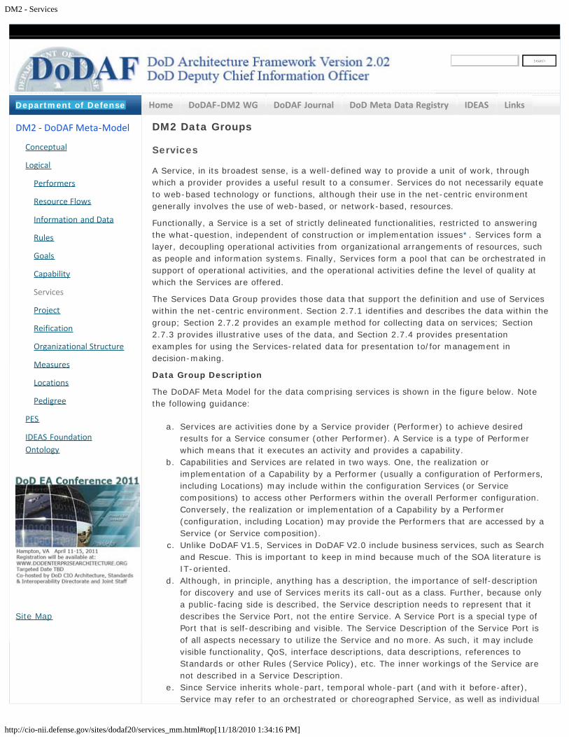
DM2 - Services
http://cio-nii.defense.gov/sites/dodaf20/services_mm.html#top[11/18/2010 1:34:16 PM]
Home DoDAF-DM2 WG DoDAF Journal DoD Meta Data Registry IDEAS Links
DM2 Data Groups
Services
A Service, in its broadest sense, is a well-defined way to provide a unit of work, throughwhich a provider provides a useful result to a consumer. Services do not necessarily equateto web-based technology or functions, although their use in the net-centric environmentgenerally involves the use of web-based, or network-based, resources.
Functionally, a Service is a set of strictly delineated functionalities, restricted to answeringthe what-question, independent of construction or implementation issues*. Services form alayer, decoupling operational activities from organizational arrangements of resources, suchas people and information systems. Finally, Services form a pool that can be orchestrated insupport of operational activities, and the operational activities define the level of quality atwhich the Services are offered.
The Services Data Group provides those data that support the definition and use of Serviceswithin the net-centric environment. Section 2.7.1 identifies and describes the data within thegroup; Section 2.7.2 provides an example method for collecting data on services; Section2.7.3 provides illustrative uses of the data, and Section 2.7.4 provides presentationexamples for using the Services-related data for presentation to/for management indecision-making.
Data Group Description
The DoDAF Meta Model for the data comprising services is shown in the figure below. Notethe following guidance:
a. Services are activities done by a Service provider (Performer) to achieve desiredresults for a Service consumer (other Performer). A Service is a type of Performerwhich means that it executes an activity and provides a capability.
b. Capabilities and Services are related in two ways. One, the realization orimplementation of a Capability by a Performer (usually a configuration of Performers,including Locations) may include within the configuration Services (or Servicecompositions) to access other Performers within the overall Performer configuration.Conversely, the realization or implementation of a Capability by a Performer(configuration, including Location) may provide the Performers that are accessed by aService (or Service composition).
c. Unlike DoDAF V1.5, Services in DoDAF V2.0 include business services, such as Searchand Rescue. This is important to keep in mind because much of the SOA literature isIT-oriented.
d. Although, in principle, anything has a description, the importance of self-descriptionfor discovery and use of Services merits its call-out as a class. Further, because onlya public-facing side is described, the Service description needs to represent that itdescribes the Service Port, not the entire Service. A Service Port is a special type ofPort that is self-describing and visible. The Service Description of the Service Port isof all aspects necessary to utilize the Service and no more. As such, it may includevisible functionality, QoS, interface descriptions, data descriptions, references toStandards or other Rules (Service Policy), etc. The inner workings of the Service arenot described in a Service Description.
e. Since Service inherits whole-part, temporal whole-part (and with it before-after),Service may refer to an orchestrated or choreographed Service, as well as individual
DM2 - DoDAF Meta-Model
Conceptual
Logical
Performers
Resource Flows
Information and Data
Rules
Goals
Capability
Services
Project
Reification
Organizational Structure
Measures
Locations
Pedigree
PES
IDEAS FoundationOntology
Site Map
Department of Defense
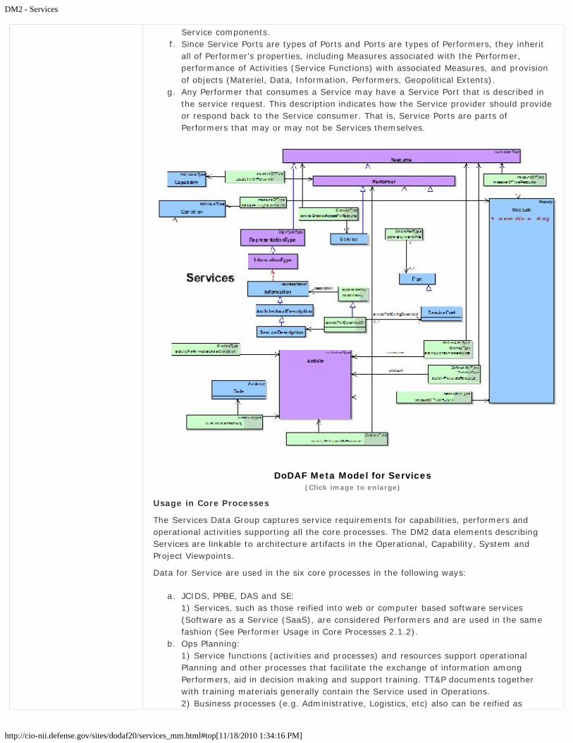
DM2 - Services
http://cio-nii.defense.gov/sites/dodaf20/services_mm.html#top[11/18/2010 1:34:16 PM]
Service components.f. Since Service Ports are types of Ports and Ports are types of Performers, they inherit
all of Performer’s properties, including Measures associated with the Performer,performance of Activities (Service Functions) with associated Measures, and provisionof objects (Materiel, Data, Information, Performers, Geopolitical Extents).
g. Any Performer that consumes a Service may have a Service Port that is described inthe service request. This description indicates how the Service provider should provideor respond back to the Service consumer. That is, Service Ports are parts ofPerformers that may or may not be Services themselves.
DoDAF Meta Model for Services(Click image to enlarge)
Usage in Core Processes
The Services Data Group captures service requirements for capabilities, performers andoperational activities supporting all the core processes. The DM2 data elements describingServices are linkable to architecture artifacts in the Operational, Capability, System andProject Viewpoints.
Data for Service are used in the six core processes in the following ways:
a. JCIDS, PPBE, DAS and SE:1) Services, such as those reified into web or computer based software services(Software as a Service (SaaS), are considered Performers and are used in the samefashion (See Performer Usage in Core Processes 2.1.2).
b. Ops Planning:1) Service functions (activities and processes) and resources support operationalPlanning and other processes that facilitate the exchange of information amongPerformers, aid in decision making and support training. TT&P documents togetherwith training materials generally contain the Service used in Operations. 2) Business processes (e.g. Administrative, Logistics, etc) also can be reified as

DM2 - Services
http://cio-nii.defense.gov/sites/dodaf20/services_mm.html#top[11/18/2010 1:34:16 PM]
Services both manual and automated. c. CPM:
1) Services such as SaaS can be part of a portofolio.
Presentation
Services are generally rendered using all the presentation techniques shown in Section1.3. Typically Structural, behavioral and tree models are used to depict Services withamplifying tabular information.
Go to top of page ?
Privacy Policy | Web Policy | Contact | Submit Change Requests

DM2 - Project
http://cio-nii.defense.gov/sites/dodaf20/project_mm.html#top[11/18/2010 1:34:31 PM]
Home DoDAF-DM2 WG DoDAF Journal DoD Meta Data Registry IDEAS Links
DM2 Data Groups
Project
A Project is a temporary endeavor undertaken to create Resources of Desired Effects.Projects are relevant to all six core processes. Projects form the major elements of the DASand are the primary focus of the DoD PPBE system.
The Primary Construct of the PPBE system is the Program Element (PE). The PE is definedas:
Program Element: The program element is the basic building block of theFuture Years Defense Program. The PE describes the program mission andidentifies the organization responsible to perform the mission. A PE may consistof forces, manpower, materiel (both real and personal property), services, andassociated costs, as applicable.
The key architectural construct within the Program Element is the Work Breakdown Structure(WBS) subject to DoD Instruction 5000.2. The WBS is the primary instrument connecting anArchitectural Description to the Defense Acquisitions System and the PPBE processes. TheWork Breakdown Structure (WBS) is defined as:
Work Breakdown Structure: “A product-oriented family tree composed ofhardware, software, services, data, and facilities. The family tree results fromsystems engineering efforts during the acquisition of a defense materiel item”.
MIL-HDBK-881A provides guidance for constructing the WBS applicable to programs subjectto DoD Instruction 5000.2. The WBS is the process necessary for subdividing the majorproduct deliverables and project work into smaller more manageable components and itserves as a valuable framework for the technical objectives, and therefore it is product-oriented. Its elements should represent identifiable work products, whether they areequipment, data, or related service products. A WBS is a product structure, not anorganizational structure, providing the complete definition of the work to be performed by allparticipants and the required interfaces between them.
Hardware, software, services, data, and facilities are Resources in the DM2. The informationcaptured in the project administrative tool/techniques (e.g., Project Management Body ofKnowledge [PMBOK] 2004) provides the basis for resource information in the DM2. The WBSforms the basis of reporting structures used for contracts requiring compliance withANSI/EIA 748 Earned Value Management System (EVMS) Guidelines and reports placed oncontract such as Contractor Cost Data Reporting (CCDR), Software Resource Data Report(SRDR), Contract Performance Reports (CPR), and Contract Funds Status Reports (CFSR).
MIL-HDBK-881A states: “…the Program WBS and Contract WBS help document architecturalproducts in a system life cycle. The DoD Architecture Framework (DoDAF) V1.0 defines acommon approach for DoD Architecture Description development, presentation, andintegration for warfighting operations and business operations and processes.”
Just as the system is defined and developed throughout its lifecycle, so is the WBS. In theearly Project phases of concept refinement, system architecture, and technologydevelopment, the program WBS is usually in an early stage of development. The results of
DM2 - DoDAF Meta-Model
Conceptual
Logical
Performers
Resource Flows
Information and Data
Rules
Goals
Capability
Services
Project
Reification
Organizational Structure
Measures
Locations
Pedigree
PES
IDEAS FoundationOntology
Site Map
Department of Defense

DM2 - Project
http://cio-nii.defense.gov/sites/dodaf20/project_mm.html#top[11/18/2010 1:34:31 PM]
the Analysis of Material Approaches and the Analysis of Alternatives (AoA) provide the basisfor the evolution of the WBS at all stages of Project evolution. As the architectural design ofthe project’s product or service matures, so should the WBS. The WBS is a primary tool inmaintaining efficient and cost effective developments of products and services. The figurebelow illustrates the evolution of the WBS during the lifecycle of Project.
Evolution of the Project WBS
A Project Plan contains the project WBS (including Tasks and responsibleOrganizations). The Project Data Group (PDG) contains the essential data required fordefining a Project Plan, e.g., those required by DoD 5000.2:
a. Acquisition Strategy
b. Technology Development Strategy
c. System Engineering Plan.
The Tasks and Performers form the essential elements of the project’s WBS. The use of bothTasks and Performers focusing on products to be delivered (e.g., System, Service, etc.) inthe WBS is the essential premise of the product-oriented WBS defined in MIL-HDBK-881A.
The Project Plan also shows plans and initiatives to coordinate transition planning in adocumented program baseline, shows critical success factors, milestones, measures,deliverables, and periodic program reviews.
Data Group Description
The DoDAF Meta Model for the data comprising Project is shown in Figure 13. There areseveral items to note regarding this model:
a. Like all concepts in the DM2, Project has whole-part, temporal whole-part,and super-subtype relationships so that major Projects can have minor Projectswithin them, Projects can have time phases, and Projects can be categorized.
b. Because a Project involves execution of a plan composed of Activities(Tasks), there is a flow of resources into the project’s activities and a flow ofproducts out of them, as described by the Resource Flow data group. So thismodel can describe a Project that results in a System, a Service, PersonnelTypes (i.e., Training), Organizations (i.e., organizational development), Materiel,or Locations (e.g., Facilities, Installations).
c. Because technology is part of the Project, this group models the analog of

DM2 - Project
http://cio-nii.defense.gov/sites/dodaf20/project_mm.html#top[11/18/2010 1:34:31 PM]
the DoDAF V 1.0 and V1.5 SV-9 (System and Services Technology Forecast)and SV-8 (System and Services Evolution Description).
d. Many kinds of measures may be associated with a Project – needs,satisfaction, performance, interoperability, organizational, and cost.
e. Measures and Rules can be assigned at all levels of the Projectdecomposition. Top-level Measures and Rules (Conditions and Constraints)could be assigned to the Vision, Goals, and Objectives (VGO). Lower-levelMeasures and Rules can then be derived and assigned to compliance and testcriteria. When part of a legal contract, policy, or directive, formal agreement, orcontract instrument, the Rules constitute a principle portion of the requirementsfor the Project.
DoDAF Meta Model for Project
Usage in Core Processes
Data for Projects are used in the following ways:
a. JCIDS1)Project is the typical outcome of the JCIDS process when material solutions areidentified. 2)Non-material solutions may also result in projects
b. PPBE, DAS , and CPM1)Project is the core element of the PPBE, DAS and CPM processes. The primaryconstruct of Project is the Work Breakdown Structure (WBS). The WBS is the primaryreification within Project that relates Performers and Activities to Cost and Milestones.As stated in MIL-HDBK-881A, the WBS is a continually evolving instrument fromProject conception to lifecycle management. This tracks closely with the evolution ofthe architecture. As key Activities are refined into primary Activities and assigned to orallocated to Performers, the WBS should mature and the project definition can gainadditional focus (reification).
2)Early Project WBSs may contain high-level Activities (Tasks, Processes, SystemFunctions, or Service Functions). As the Project matures, the WBS identifies thesystem components, such as subsystems and software configuration items (SCIs). TheSCIs can be software services or individually testable and deliverable packages of
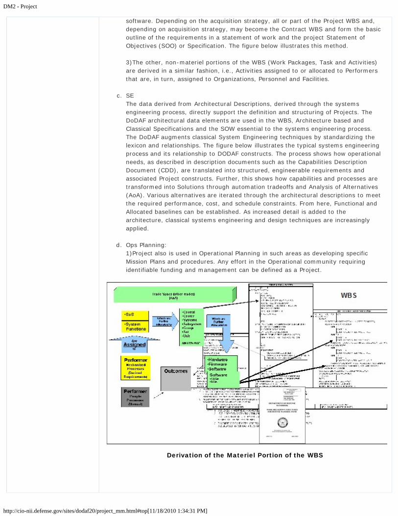
DM2 - Project
http://cio-nii.defense.gov/sites/dodaf20/project_mm.html#top[11/18/2010 1:34:31 PM]
software. Depending on the acquisition strategy, all or part of the Project WBS and,depending on acquisition strategy, may become the Contract WBS and form the basicoutline of the requirements in a statement of work and the project Statement ofObjectives (SOO) or Specification. The figure below illustrates this method.
3)The other, non-materiel portions of the WBS (Work Packages, Task and Activities)are derived in a similar fashion, i.e., Activities assigned to or allocated to Performersthat are, in turn, assigned to Organizations, Personnel and Facilities.
c. SE The data derived from Architectural Descriptions, derived through the systemsengineering process, directly support the definition and structuring of Projects. TheDoDAF architectural data elements are used in the WBS, Architecture based andClassical Specifications and the SOW essential to the systems engineering process.The DoDAF augments classical System Engineering techniques by standardizing thelexicon and relationships. The figure below illustrates the typical systems engineeringprocess and its relationship to DODAF constructs. The process shows how operationalneeds, as described in description documents such as the Capabilities DescriptionDocument (CDD), are translated into structured, engineerable requirements andassociated Project constructs. Further, this shows how capabilities and processes aretransformed into Solutions through automation tradeoffs and Analysis of Alternatives(AoA). Various alternatives are iterated through the architectural descriptions to meetthe required performance, cost, and schedule constraints. From here, Functional andAllocated baselines can be established. As increased detail is added to thearchitecture, classical systems engineering and design techniques are increasinglyapplied.
d. Ops Planning: 1)Project also is used in Operational Planning in such areas as developing specificMission Plans and procedures. Any effort in the Operational community requiringidentifiable funding and management can be defined as a Project.
Derivation of the Materiel Portion of the WBS
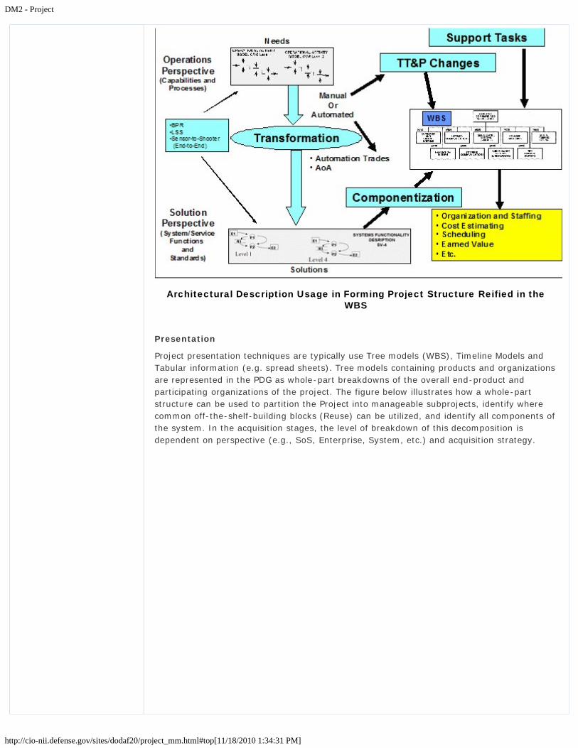
DM2 - Project
http://cio-nii.defense.gov/sites/dodaf20/project_mm.html#top[11/18/2010 1:34:31 PM]
Architectural Description Usage in Forming Project Structure Reified in theWBS
Presentation
Project presentation techniques are typically use Tree models (WBS), Timeline Models andTabular information (e.g. spread sheets). Tree models containing products and organizationsare represented in the PDG as whole-part breakdowns of the overall end-product andparticipating organizations of the project. The figure below illustrates how a whole-partstructure can be used to partition the Project into manageable subprojects, identify wherecommon off-the-shelf-building blocks (Reuse) can be utilized, and identify all components ofthe system. In the acquisition stages, the level of breakdown of this decomposition isdependent on perspective (e.g., SoS, Enterprise, System, etc.) and acquisition strategy.

DM2 - Project
http://cio-nii.defense.gov/sites/dodaf20/project_mm.html#top[11/18/2010 1:34:31 PM]
Non-prescriptive, Illustrative Example of System Project Decomposition Usedto Develop the Product Portion of the WBS
Go to top of page ?
Privacy Policy | Web Policy | Contact | Submit Change Requests

DM2 - Reification
http://cio-nii.defense.gov/sites/dodaf20/reification.html[11/18/2010 1:34:44 PM]
Home DoDAF-DM2 WG DoDAF Journal DoD Meta Data Registry IDEAS Links
DM2 Data Groups
Reification
Architectural descriptions such as activity models are example of architectural descriptionsthat reified at many level of detail. In a typical development project, the architecturedescriptions (contained in plans, specifications and/or “model based” Computer Aided DesignTools (CAD)) provide increasing levels of detail as the project progresses through the normalDoD Milestone process. This is what John Zachman calls “levels of reification”, as shown inthe figure below.
Reification of Architectural Descriptions at Varying Levels(Click image to enlarge)
Data Group Description
The DoDAF Meta Model for the data comprising reification is shown in the figure below.
DM2 - DoDAF Meta-Model
Conceptual
Logical
Performers
Resource Flows
Information and Data
Rules
Goals
Capability
Services
Project
Reification
Organizational Structure
Measures
Locations
Pedigree
PES
IDEAS FoundationOntology
Site Map
Department of Defense

DM2 - Reification
http://cio-nii.defense.gov/sites/dodaf20/reification.html[11/18/2010 1:34:44 PM]
DoDAF Meta Model for Reification(Click image to enlarge)
Usage in Core Processes
Reification is used in the six core processes in the following ways:
a. JCIDS: Refinement and increased levels of detail of capability and solution constraintdescriptions from ICD to CPD.
b. PPBE: Refinement in Project or Program Work Breakdown Structures (WBSs) and Costto complete estimates.
c. DAS: Refinement and Increase detail of design and architectural descriptions throughthe milestone review process.
d. SE:1) Refinement and Increase detail of design and architectural descriptions through thevarious design and development stages.2) Clearly described functional allocations and traceability throughout the variouslevels of architectural descriptions (e.g. specifications, architectural view and models).
e. Ops Planning: Refinement and increasing levels of detail in Tactics, Techniques andProcedures throughout the stages of operational plan development.
f. CPM: Refinement and increased detail in the descriptions of the capability,performance, functionality and cost effectiveness of the portfolio.
Presentation
Reification is depicted throughout all the elements of the architectural descriptions. It isevident in all levels of design detail or refinement. From one level to another level differentpeople become involved in the architecture and design process. The reification processillustrates that at different levels, “one person’s design becomes the next person’srequirement”. Reification can take all forms of descriptive techniques. Typically thestructural, behavior, tree models and views will be present throughout all the normalprograms documentation (e.g. specifications, system engineering plans, procedural

DM2 - Reification
http://cio-nii.defense.gov/sites/dodaf20/reification.html[11/18/2010 1:34:44 PM]
documents, training manuals, doctrine publications, etc.)
Go to top of page ?
Privacy Policy | Web Policy | Contact | Submit Change Requests

DM2 - Organizational Structure
http://cio-nii.defense.gov/sites/dodaf20/organizational.html[11/18/2010 1:34:58 PM]
Home DoDAF-DM2 WG DoDAF Journal DoD Meta Data Registry IDEAS Links
DM2 Data Groups
Organizational Structure
Data Group Description
The DoDAF Meta Model for the data comprising organizational structure is shown in thefigure below.
DoDAF Meta Model for Organizational Structure(Click image to enlarge)
Usage in Core Process
Presentation
Go to top of page ?
DM2 - DoDAF Meta-Model
Conceptual
Logical
Performers
Resource Flows
Information and Data
Rules
Goals
Capability
Services
Project
Reification
Organizational Structure
Measures
Locations
Pedigree
PES
IDEAS FoundationOntology
Site Map
Department of Defense

DM2 - Organizational Structure
http://cio-nii.defense.gov/sites/dodaf20/organizational.html[11/18/2010 1:34:58 PM]
Privacy Policy | Web Policy | Contact | Submit Change Requests

DM2 - Measures
http://cio-nii.defense.gov/sites/dodaf20/measures.html[11/18/2010 1:35:06 PM]
Home DoDAF-DM2 WG DoDAF Journal DoD Meta Data Registry IDEAS Links
DM2 Data Groups
Measures
A measure is the magnitude of some attribute of an object. Measures provide a way tocompare objects, whether Projects, Services, Systems, Activities, or Capabilities. Thecomparisons can be between like objects at a point in time, or the same object over time.For example, a Capability may have different measures when looking at the current baselineand over increments toward some desired end-state. Measures play a much greater, centralrole in DoDAF V2.0, compared to earlier versions of DoDAF. This change has multipledrivers, including: Core Process use of architectural data. Those management andengineering processes depend on quantification as a means of improving objectivity,accountability, and efficiency of the processes. Federal Enterprise Architecture (FEA)Performance Reference Model. There are many kinds of Measures that are applicable tomany architecture elements. These are described in the following paragraph.
Data Group Description
The DoDAF Meta Model for the data comprising Measures, is depicted in the figure below.
DoDAF Meta Model for Measures(Click image to enlarge)
The following should be noted about the Measures Data Group:
a. The key elements of the Measure Data group are Measure and Measure Type. Measurerefers to the actual measure value and units. It relates to a Measure Type thatdescribes what is being measured. Examples of each are shown below in the table
DM2 - DoDAF Meta-Model
Conceptual
Logical
Performers
Resource Flows
Information and Data
Rules
Goals
Capability
Services
Project
Reification
Organizational Structure
Measures
Locations
Pedigree
PES
IDEAS FoundationOntology
Site Map
Department of Defense

DM2 - Measures
http://cio-nii.defense.gov/sites/dodaf20/measures.html[11/18/2010 1:35:06 PM]
below.
Non-prescriptive, Illustrative Examples of Measures and Measure Types
b. Formally, a Measure defines membership criteria for a set or class; e.g., the set of allthings that has 2 kg mass. The relationship between Measure and Measure Type isthat any particular Measure is an instance of all the possible sets that could be takenfor a Measure Type.
c. The lower part of Figure 20 depicts the upper tiers of a Measure Type taxonomy orclassification scheme. It is expected that architects would add more detailed types(make the taxonomy more specialized), as needed, within their federate. Note thatService Level has multiple inheritances because a Service QoS or Service LevelAgreement (SLA) could address User Needs, User Satisfaction, Interoperability, orPerformance.
d. All Measure Types have a Rule that prescribes how the Measure is accomplished; e.g.,units, calibration, or procedure. Spatial measures’ Rules include coordinate systemrules. For example, latitude and longitude are understandable only by reference to aGeodetic coordinate system around the Earth.
e. As a Measure Type, cost can be captured in the architecture at different levels, basedon the Process-owners requirements
f. The upper part of the figure above depicts how Measures apply to architectureelements. Note that they apply to relationships between objects; e.g., the Measureapplies to a Performer performing an Activity. The Activity has a relationship toMeasure Type that says what Measure Types apply to an Activity. This representsUniversal Joint Task List (UJTL) tasks and their applicable Measure Types, includingConditions, that is, Condition is quantified by a Measure Type. (The whole-partrelationship feature of Condition allows it to be singular.) This is accomplished byCondition’s typeInstance association, saying an elementary Condition is a member(instance) of a Measure Type class.
Usage in Core Processes
Data for Measures are used in the six core processes in the following ways:
PPBE and JCIDS:
1. Planning – adequacy analysis: From an adequacy point of view, Measures that areassociated with a Capability (including Capability increment, since Capabilities havewhole-part inheritance). Capabilities can be compared with the Measures associated
DM2 - Measures
http://cio-nii.defense.gov/sites/dodaf20/measures.html[11/18/2010 1:35:06 PM]
with the Performers to see if the Performer solution(s) are adequate. A set ofalternative Performers as part of an Analysis of Alternatives could also be evaluated.Goals or Desired Effects could compare with Measures associated with Performers.
2. Programming – overlap analysis: The purpose of an overlap analysis is to determine ifthere are overlaps, or undesired duplicative capability, in the spending plan, portfolio,capabilities development, or acquisition plan. Similar functionality is often only anindicator of overlapping or duplicative capability. Often Performers with similarfunctionality operate under different Measures which are not duplicative or overlappingcapability. For example, operational-level situation awareness systems may not be asfast or precise as a tactical-level, but they may handle a larger number of objectsover a larger area.
3. Goal Setting: Measures are often part of Goals; e.g., production or efficiency Goals.4. Requirements: Requirements often have Measure elements.5. Capability Evolution: Measures are part of capability evolution, showing increments of
measurable improvement as the capability evolves and allowing monitoring aboutwhen the capability is projected to be achieved or has already been achieved.
SE and DAS:
1. System Engineering/Design: Measures set the design envelope goals, sometimescalled performance characteristics or attributes. They can also set the constraints;e.g., cost constraints.
2. Performance–Cost Tradeoffs: Measures of performance (e.g., effectiveness) can becompared to different costs to evaluate and make decisions about alternativesolutions.
3. Benchmarking: Measures can be used to establish benchmarks of performance, suchas for a personnel skill or a radar tracking accuracy test.
4. Organizational and Personnel Development: Organizational and personnel goals areoften established and then monitored using Measures.
5. Capacity Planning: Measures can be used to plan for needed capacity; e.g., fornetworks, training programs.
6. Quality of Service (QoS) Description: In SOA, QoS is often expressed as a Measure;e.g., bit loss rate or jitter. These Measures show up in the service description and arepart of service discovery, so users can discover access to capabilities that meet theirquality requirements.
7. Project Constraints: Measures such as cost and risk can be constraints on Projects.
CPM:
1. Portfolio Balancing. Measures can be used to balance a portfolio so that it achieves theright mix of goals and constraints.
Ops Planning:
1. Organizational and Personnel Development. Organizational and personnel goals areoften established and then monitored using Measures.
Presentation
Presentation Measures are typically displayed in tabular form and are usually tied toStructural, Behavioral or Tree models and their constituent elements. Measures can also berepresented in a tree structure illustrating the traceability of derived metric requirements.
Go to top of page ?

DM2 - Measures
http://cio-nii.defense.gov/sites/dodaf20/measures.html[11/18/2010 1:35:06 PM]
Privacy Policy | Web Policy | Contact | Submit Change Requests

DM2 - Locations
http://cio-nii.defense.gov/sites/dodaf20/locations.html[11/18/2010 4:43:44 PM]
Home DoDAF-DM2 WG DoDAF Journal DoD Meta Data Registry IDEAS Links
DM2 Data Groups
Locations
A location is a point or extent in space. The need to specify or describe Locations occurs insome Architectural Descriptions when it is necessary to support decision-making of a coreprocess. Examples of core process analyzes in which locations might have a bearing on thedecisions to be made include the following:
1. Base Realignment and Closure (BRAC) (SE process).2. Capability for a new regional command (JCIDS).3. Communications or logistics planning in a mission area (Ops process).4. System and equipment installation and Personnel Type assignments to Facilities
(Operations and SE processes).
Examples where Locations play little, if any, role in the process are:
1. Prioritization of precision engagement programs (PPBE and portfolio managementprocesses).
2. Streamlining of a business process (SE process).3. Doctrine development (JCIDS and Operations processes).
The role of Locations in the decision process was implicit in earlier versions of DoDAF. In thisversion, they are treated explicitly and precisely to allow more rigorous analysis ofrequirements (e.g., communications or logistics planning) and clearer differentiation amongsolutions alternatives).
Data Group Description
The DoDAF Meta-model for the data comprising Locations is shown in the figure below. There are several items to note:
a. Addresses such as URLs, Universal Resource Names (URNs), postal addresses, datalink addresses, etc. are considered Names for Locations. For example, a postaladdress is a naming system for the Location of a building. A Universal ResourceLocator is a name for a server that is located somewhere on the Web.
b. The naming pattern works by identifying the following:1) the name string, 2) the object being named, and 3) the type of name (e.g., postal address). Name here is used in the broadest sense,such that a description is considered a long name.
c. The lower left of the diagram is a model of types of Location objects. These can bealternatively named using the naming pattern in the upper left and delineated usingthe Extent pattern in the lower right.
d. Minimal parts of the Spatial Extent (Point, Line, Surface, and Solid Volume) aredetailed because of the varying requirements within a federate. That is, member ofthe federate may need to specialize the Spatial Extents. Some common and simpleclasses are modeled, such as a Line described by two Points and a Planar Surfacedefined by a Line and Point.
e. Facilities are types of Locations. In prior versions of DoDAF it was not clear if a Facility
DM2 - DoDAF Meta-Model
Conceptual
Logical
Performers
Resource Flows
Information and Data
Rules
Goals
Capability
Services
Project
Reification
Organizational Structure
Measures
Locations
Pedigree
PES
IDEAS FoundationOntology
Site Map
Department of Defense

DM2 - Locations
http://cio-nii.defense.gov/sites/dodaf20/locations.html[11/18/2010 4:43:44 PM]
could be thought of as a system or just a Location. This is now clarified. To describethe functionality of a Facility, the Activities performed by the Performers located at theFacility are described.
f. Installation, Site, and Facility follow Army guidance from the Real Property InventoryRequirements (RIPR). Similarly, a Facility can be a linear structure, such as a road orpipeline.
g. Geofeatures (called FEATURE in Joint Consultation, Command and Control InformationExchange Data Model (JC3IEDM)) cover man-made control features, as well asgeophysical features (including meteorological and oceanographic phenomena).
DoDAF Meta Model for Locations(Click image to enlarge)
Additional considerations in modeling Location data are as follows:
a. For many architecture applications, a locating scheme is some kind of geometricsystem because many uses (see next paragraph) require geometric calculations.
b. Named locations (e.g., facility, base, installation, region names) can be applicablesince their use may be merely to describe where performance occurs. In addition, thenaming pattern basically can use the name as a surrogate for the geometric location,such as postal addresses are rarely applicable to architectures.
c. If a geometric system is needed, the coordinate system, reference frame, and unitsare chosen. The Geospatial Markup Language (GML) defines 26 different kinds ofcoordinate systems, including one called user defined. In many cases, a federate maychoose reference to GML so issues like handed-ness and orientation don’t have to bedefined again.
d. The accuracy should be determined. For many uses, Locations may not need to be asaccurate as some Geospatial system can be, since the use calculation may have manyapproximations, assumptions, and minor influencing variables that are chosen to beignored.
e. In some cases, there may be need for speed and acceleration ranges. Since these areunusual, they are not part of the core DM2 but would be added as extensions for thesekinds of models. The speed could be extended as an attribute or as a trajectoryconsisting of a set of spatial-temporal points, where the trajectory is a whole and thepoints are parts.
Usage in Core Processes

DM2 - Locations
http://cio-nii.defense.gov/sites/dodaf20/locations.html[11/18/2010 4:43:44 PM]
Data for Locations are used to describe where Performers perform. The Location conceptsupported the system node in DoDAF V1.0 and V1.5. In DoDAF V2.0, it is generalized andmore precisely defined. Examples of the uses of the various types of Locations in all the coreprocesses are:
a. Facility Locations allow description that certain systems or organizations are located ata specific facility. Note that the function of the Facility is determined by the Activitiesperformed by the Performers located at the Facility; that is, the Facility itself is not aPerformer.
b. Installation Locations allow descriptions of certain organizations that operate or use aninstallation.
c. Region Locations are used to describe what Performers and Activities are performed incertain regions.
d. A Point Location can be used to state when a Performer is located at a specific Point;e.g., latitude and longitude. When the location is not that specific, Regions, Countries,and other geometric shapes can be used.
e. Line (set of lines) allows description of Performers located on, beside, or within someenclosing lines. The line could be described mathematically so that it could specify anorbit, e.g., that certain satellites are in some orbit.
f. Volume, e.g., that some systems cover a certain volume; e.g., an air defense system.g. Addresses (names for locations) allow descriptions of where something is located
using the address scheme; e.g., the URL address scheme allows for looking up theinternet protocol (IP) and then the files on the server.
Presentation
Location is typically represented in architecture in pictorial diagrams, however tabular andother representations may be used depending on the “Fit-for-Purpose” application. In manyinstances, locations are depicted in conjunction with typical models and view used inarchitectural descriptions.
Go to top of page ?
Privacy Policy | Web Policy | Contact | Submit Change Requests

DM2 - Pedigree
http://cio-nii.defense.gov/sites/dodaf20/pedigree.html[11/18/2010 4:44:00 PM]
Home DoDAF-DM2 WG DoDAF Journal DoD Meta Data Registry IDEAS Links
DM2 Data Groups
Pedigree
The pedigree data group represents the workflow for a Resource. It describes the Activitiesused to produce a Resource, e.g., a piece of Information. Of particularly high importance forarchitectural descriptions, is the production of architecture descriptioninformation. (Architecture descriptions are types of Information since Information describessome Thing and architecture descriptions describe the architecture.) All aspects of theproduction workflow are describable with the Pedigree data group including:
a. What Resources were consumed in the production of the Resource
b. What Performers performed the production
c. What Rules constrained the production activity
d. What metrics (Measures) applied to the production and the Resources consumed
e. Where did the production occur
Data Group Description
The DoDAF Meta Model for the data comprising Pedigree is shown in the figure below.
DoDAF Meta Model for Pedigree(Click image to enlarge)
DM2 - DoDAF Meta-Model
Conceptual
Logical
Performers
Resource Flows
Information and Data
Rules
Goals
Capability
Services
Project
Reification
Organizational Structure
Measures
Locations
Pedigree
PES
IDEAS FoundationOntology
Site Map
Department of Defense

DM2 - Pedigree
http://cio-nii.defense.gov/sites/dodaf20/pedigree.html[11/18/2010 4:44:00 PM]
Usage in Core Processes
Pedigree is used to demonstrate the rationale for architecture description choices. In manysystems engineering and requirements analysis processes, it is the means by whichtraceability information is maintained.
Presentation
Pedigree information is usually presented in traceability matrices, tables, or indented text.Sometime reverse-traceability information is presented, wherein the source (e.g.,requirement) is listed and then the architectural artifacts that satisfy it are shown next.
Go to top of page ?
Privacy Policy | Web Policy | Contact | Submit Change Requests

Physical Exchange Specification
http://cio-nii.defense.gov/sites/dodaf20/PES.html[11/18/2010 4:44:34 PM]
Home DoDAF-DM2 WG DoDAF Journal DoD Meta Data Registry IDEAS Links
DM2
DoDAF Physical Exchange Specification (PES)
In the support of these, EA data must be exchanged and shared. The general pattern for thisexchange is shown in the figure below.
General Pattern for EA Information Sharing and Data Exchange
The information to be shared varies across the core processes and is determined by theinformation needs of specific use cases within those core processes. Notional examples ofsuch use cases are shown in the figure below.
Introduction
What is New in DoDAF V2.0
Vision for DoDAF V2.0
Architecture Resources
DoDAF V1.5 Support
Relationships to otherFrameworks
Background
Architecture Development
Viewpoints
Models
DM2 - DoDAF Meta-Model
Conceptual
Logical
PES
IDEAS FoundationOntology
Architect Role
Developer Role
Site Map
Department of Defense

Physical Exchange Specification
http://cio-nii.defense.gov/sites/dodaf20/PES.html[11/18/2010 4:44:34 PM]
Notional EA Information Sharing Use Cases
Core process use case stakeholders work with EA data developers to determine whatinformation needs to be shared when in order to support the core process. A notionalexample of the resultant information exchange in shown in the figure below. Note that in thiscase, the data presented for decisions may not be EA data, but, rather, the analysis resultsfrom analyzing EA data.
Notional Pattern of EA Information Sharing for Assessment Processes
When exchanging architectural data, the PES is the specification for the exchange. The PESprovides an efficient and standard means to ensure that data sharing can occur in a toolset-agnostic, methodology-agnostic environment. Use of the by architects to documentarchitectural data and information in tools, through spreadsheets, or other means, anddeposit that data and organized information into federated repositories is facilitated by thecommon understanding underlying the use of the PES.

Physical Exchange Specification
http://cio-nii.defense.gov/sites/dodaf20/PES.html[11/18/2010 4:44:34 PM]
The DM2 PES XML schema (XSD) provides a neutral format for data exchange between EAdata and data sources including:
1. EA databases.2. DoD Authoritative Source Databases (e.g., DoD Information Technology Portfolio
Repository [DITPR]).3. Unified Profile for DoDAF and Ministry of Defence Architecture Framework (MODAF)
(UPDM) and SysML-based Unified Markup Language (UML) Tools.4. Other Information Technology (IT) and enterprise architecture Tools.5. Modeling and Simulation Tools that are used in EA assessments, e.g., AoA’s.6. Reporting Tools, e.g., for Chairman of the Joint Chief of Staff Instruction (CJCSI) or
Department of Defense Instruction (DoDI) submission.7. Systems Engineering Tools.8. Other Federal agencies (e.g., Department of Homeland Security (DHS), Department of
Justice (DoJ).9. Coalition partners and North Atlantic Treaty Organization (NATO).
10. Other organizations with which DoD exchanges Enterprise Architecture (EA) data(e.g., industry, States, National Government Organizations [NGO’s]).
This role is illustrated in the figure below.
Illustration of DM2 Role in Providing a Neutral Model for Data Exchange
Note that within any particular community above, there may be a data exchange formatparticular to that community. A particularly important case is the UPDM-SysML XMLMetadata Interchange (XMI) format for data exchange of UML models. XMI provides aneutral way to exchange model data, including diagram data, between UML tools. A universalDM2 PES to XMI translation will allow UPDM-SysML tools to interoperate with the other toolsand data sources used in DoD EA.
XSD
The DM2 PES eXtensible Markup Language (XML) Schema Definitions (XSDs) is auto-generated from the DM2 Logical Data Model. No additional semantics are added or changed.
There are four DM2 PES XSD’s:

Physical Exchange Specification
http://cio-nii.defense.gov/sites/dodaf20/PES.html[11/18/2010 4:44:34 PM]
1. IDEAS Foundation, version 1.02. DM2 additional foundation3. Classification marking (externally controlled)4. DM2 exchange data
The DM2 PES XSD used for data exchange has a very simple structure as shown in the figurebelow.
Top-Level Structure of a the DM2 PES XSD for Exchange
The IdeasData section contains all the DM2 domain data in a flat structure with elementslinked together using standard XML document IDref’s. A piece of this flat structure is shownin the figure below. All of the DM2 data that is to be exchanged is contained in this section.
Sample of the IdeasData Section of the DM2 PES XSD for Data Exchange
The IdeasViews section then specifies what DoDAF views this data pertains to. A sample ofthis section is shown in the figure below. If a DM2 PES XML document is received and theseviews are indicated as being represented in the dataset, this XSD can be used to validate thedocument, to see that the mandatory data is present and that data that is not optional is notcontained.

Physical Exchange Specification
http://cio-nii.defense.gov/sites/dodaf20/PES.html[11/18/2010 4:44:34 PM]
Sample of the IdeasViews Section of the DM2 PES XSD for Data Exchange
The PES XSD's can be downloaded here:
IDEAS FoundationDM2 FoundationDM2 DomainIC-ISM
In-progress examples of DM2 PES XML documents are available to DM2 Working Groupmembers on the DM2 Collaboration Site www.silverbulletinc.com/dm2, and will be madeavailable to the entire EA community on the DoDAF Journal.
Go to top of page ?
Privacy Policy | Web Policy | Contact | Submit Change Requests
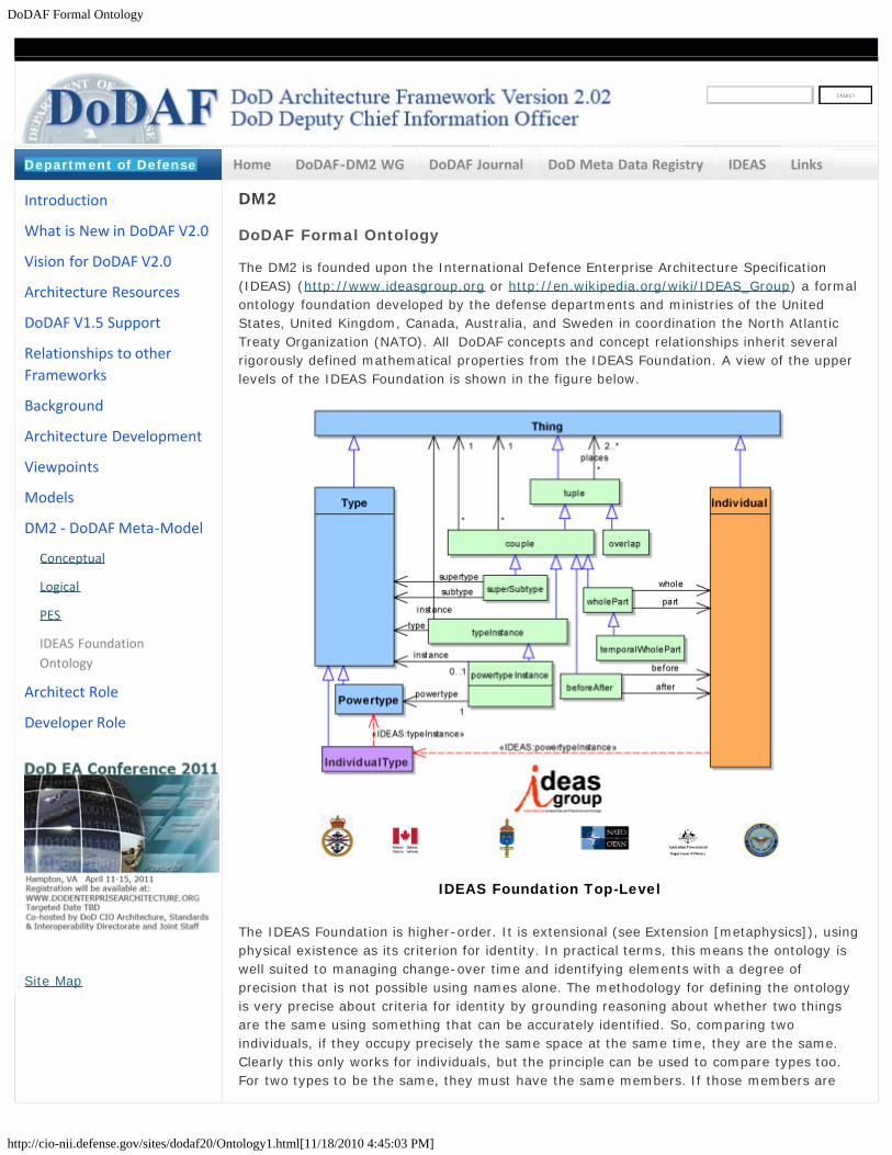
DoDAF Formal Ontology
http://cio-nii.defense.gov/sites/dodaf20/Ontology1.html[11/18/2010 4:45:03 PM]
Home DoDAF-DM2 WG DoDAF Journal DoD Meta Data Registry IDEAS Links
DM2
DoDAF Formal Ontology
The DM2 is founded upon the International Defence Enterprise Architecture Specification(IDEAS) (http://www.ideasgroup.org or http://en.wikipedia.org/wiki/IDEAS_Group) a formalontology foundation developed by the defense departments and ministries of the UnitedStates, United Kingdom, Canada, Australia, and Sweden in coordination the North AtlanticTreaty Organization (NATO). All DoDAF concepts and concept relationships inherit severalrigorously defined mathematical properties from the IDEAS Foundation. A view of the upperlevels of the IDEAS Foundation is shown in the figure below.
IDEAS Foundation Top-Level
The IDEAS Foundation is higher-order. It is extensional (see Extension [metaphysics]), usingphysical existence as its criterion for identity. In practical terms, this means the ontology iswell suited to managing change-over time and identifying elements with a degree ofprecision that is not possible using names alone. The methodology for defining the ontologyis very precise about criteria for identity by grounding reasoning about whether two thingsare the same using something that can be accurately identified. So, comparing twoindividuals, if they occupy precisely the same space at the same time, they are the same.Clearly this only works for individuals, but the principle can be used to compare types too.For two types to be the same, they must have the same members. If those members are
Introduction
What is New in DoDAF V2.0
Vision for DoDAF V2.0
Architecture Resources
DoDAF V1.5 Support
Relationships to otherFrameworks
Background
Architecture Development
Viewpoints
Models
DM2 - DoDAF Meta-Model
Conceptual
Logical
PES
IDEAS FoundationOntology
Architect Role
Developer Role
Site Map
Department of Defense

DoDAF Formal Ontology
http://cio-nii.defense.gov/sites/dodaf20/Ontology1.html[11/18/2010 4:45:03 PM]
individuals, their physical extents can be compared. If the members are types, then theanalysis continues until individuals are reached, then they can be compared. The advantageof this methodology is that names are separated from things and so there is no possibility ofconfusion about what is being discussed. It is also four dimensionalist so that temporal parts(or states) can be represented, along with before-after behaviors. A partial bibliography ofresearch and reference material used in deriving the IDEAS Foundation is included in theappendix to this document.
None of these foundation properties are unusual; they are all used in reasoning everyday. The basic concepts are:
1. Three basic types of Things:Individuals are Things that exist in 3D space and time, i.e., have 4D spatial-temporal extent.Types, sets or collections of things. Two important Types are distinguished –ones whose members are Individuals and those whose members are other thanIndividuals. This is an important distinction between naïve set theory and typetheory.Tuples, ordered relations between things, e.g., ordered pairs in 2D analyticgeometry, rows in relational database tables, and subject-verb-object triples inResource Description Framework.
2. Basic relationships:Set theoretic:
Super-subtype; e.g., a type of system or service, capability, materiel,organization, or condition.Type-instance, similar to “element of” in set theory
Mereologic:Whole-part; e.g., components of a service or system, parts of the data,materiel parts, subdivisions of an activity, and elements of a measure.Temporal whole-part; e.g., the states or phases of a performer, theincrements of a capability or projects, the sequence of a process(activity).
4D Topologic:OverlapBefore-after
Items of note:
1. Types include sets of Tuples and sets of sets.
2. Tuples can have other Tuples in their tuple places.
3. The participants in a super-subtype relationship can be from the same class, e.g., thesupertype can be an instance of Measure Type as well as the subtype. This allows forrepresentation of as much of a super-subtype taxonomy as is needed.
4. Power Type members are generated from some Type by taking all the possiblesubsets of the members of the Type. For example consider the Type whose membersare a, b, c. The powerset would be:
5. For example, take the Individual Type AIRCRAFT, whose members include all theaircraft of the world. The powerset generated from this set would have:
6. Some of these subsets are not used by anyone, e.g., the full set, the null set, or just

DoDAF Formal Ontology
http://cio-nii.defense.gov/sites/dodaf20/Ontology1.html[11/18/2010 4:45:03 PM]
some random subset. However, the second one, which might be name F-15 Type, isquite useful. The last example is not useful to most unless you are interested in thefirst (assuming the subscript 1 means first) of any particular aircraft type, e.g., if youwere doing a study of first-off-the-line aircraft production lessons-learned. This is theusefulness of Power Types and why they are employed in DM2: they allow for multiplecategorization schemes, according to someone else’s use, yet traceability back to thecommon elements so that the relationships between multiple categorization schemescan be understood. This was a DM2 requirement – multiple categorization schemes ortaxonomies – because across a large enterprise it is not possible to employ a singlecategorization scheme; rather schemes vary depending on function. For example, aweaponeer’s classifies ordnance is naturally different from a logistician’s, the formerconcerned with delivery means, lethality, etc. and the latter with weight, size, andother transportation issues.
7. Note also that a powerset can then be taken of the powerset. This allows for build upof what is often called a taxonomic hierarchy. These are quite useful in enterpriseArchitectural Descriptions.
The DM2 utilizes the formal ontology of IDEAS because it provides:
1. Mathematical rigor needed for precision Architectural Descriptions that can beanalyzed and used in detailed processes such as Systems Engineering and OperationsPlanning.
type (~set) theory4D mereotopology
2. Deals with issues of states, powertypes, measures, space -- what is truly knowable vs.what is assumed
3. Separates signs and representations from referents4. DM2 domain concepts are extensions to the formal foundation
Rigorously worked-out common patterns are reused: Super-subtype, whole-part, temporal whole-part, type-instance, before-after, overlapSaved a lot of repetitive work – “ontologic free lunch”Model compactness through inheritance of superclass properties and commonpatterns.Economizes implementationsHigher quality and consistency throughout due reuse of the rigorously worked-out common patterns
5. Improved interoperation with Unified Profile for DoDAF and MODAF (UPDM)-SysMLtools which are following IDEAS concepts.
6. Improved opportunities for Coalition and NATO data exchange since MODAF isfollowing IDEAS and NAF is interested in following IDEAS.
7. Agreed-upon analysis principles that provide a principled basis for issue analysis8. Better ability to integrate and analyze EA data for EA purposes.
The advantage over free-text, structured documents, and databases in using this type ofmathematically structured information is somewhat explained by the figure below that showsa spectrum of information structuring.

DoDAF Formal Ontology
http://cio-nii.defense.gov/sites/dodaf20/Ontology1.html[11/18/2010 4:45:03 PM]
A Spectrum of Information Structuring
This shows that databases are really just storage and retrieval with connections only forexactly matching pieces of information (e.g., "keys" or exactly matching strings). The natureand purposes of EA require more than just storage, retrieval, and exchange, e.g.,integration, analysis, and assessment across datasets. Founding DM2 on IDEAS provides theontologic foundation supports entailment and other sorts of mathematical understanding ofthe data with membership (~ set theory) and 4D mereotopology (parts and boundaries). Some of these structures are so fundamental in human reasoning that it's hard to see thatcomputers don't have it at all. But they are needed if we want to use them for somethingmore than just storage and retrieval. They have to be encoded it into them with formalmethods.
Common Patterns
The re-use patterns useful to Architectural Descriptions are shown in the figure below.
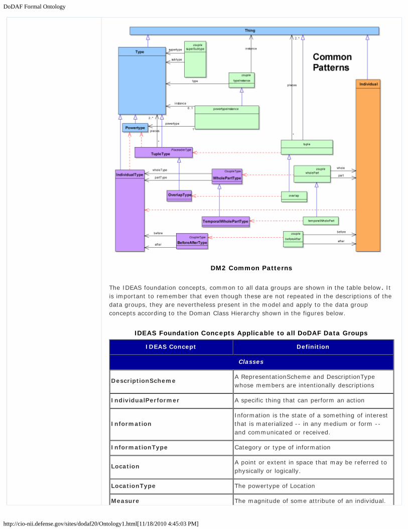
DoDAF Formal Ontology
http://cio-nii.defense.gov/sites/dodaf20/Ontology1.html[11/18/2010 4:45:03 PM]
DM2 Common Patterns
The IDEAS foundation concepts, common to all data groups are shown in the table below. Itis important to remember that even though these are not repeated in the descriptions of thedata groups, they are nevertheless present in the model and apply to the data groupconcepts according to the Doman Class Hierarchy shown in the figures below.
IDEAS Foundation Concepts Applicable to all DoDAF Data Groups
IDEAS Concept Definition
Classes
DescriptionSchemeA RepresentationScheme and DescriptionTypewhose members are intentionally descriptions
IndividualPerformer A specific thing that can perform an action
InformationInformation is the state of a something of interestthat is materialized -- in any medium or form --and communicated or received.
InformationType Category or type of information
LocationA point or extent in space that may be referred tophysically or logically.
LocationType The powertype of Location
Measure The magnitude of some attribute of an individual.

DoDAF Formal Ontology
http://cio-nii.defense.gov/sites/dodaf20/Ontology1.html[11/18/2010 4:45:03 PM]
MeasureType A category of Measures
PerformerAny entity - human, automated, or anyaggregation of human and/or automated - thatperforms an activity and provides a capability.
RepresentationA SignType where all the individual Signs areintended to signify the same Thing.
RepresentationSchemeA RepresentationType that is a collection ofRepresentations that are intended to be thepreferred Representations in certain contexts.
ResourceData, Information, Performers, Materiel, orPersonnel Types that are produced or consumed.
RuleA principle or condition that governs behavior; aprescribed guide for conduct or action
ServiceLevelA measurement of the performance of a system orservice.
Thing The union of Individual, Type, and tuple.
Associations
beforeAfter
A couple that represents that the temporal extentend time for the individual in place 1 is less thantemporal extent start time for the individual inplace 2.
BeforeAfterType
An association between two Individual Typessignifying that the temporal end of all theIndividuals of one Individual Type is before thetemporal start of all the Individuals of the otherIndividual Type.
describedByA tuple that asserts that Information describes aThing.
descriptionSchemeInstanceA representationSchemeInstance that asserts aDescription is a member of a DescriptionScheme.
endBoundaryA temporal whole part couple that relates thetemporal boundary to the whole.
EndBoundaryTypeA temporal whole part couple that relates thetemporal boundary to the whole taken over a Type.
measureOfIndividualEndBoundary endBoundary is a member of Measure
measureOfIndividualStartBoundary startBoundary is a member of Measure
measureOfTypeEndBoundaryType endBoundaryType is a member of Measure
measureOfTypeStartBoundaryType startBoundaryType is a member of Measure
namedByA couple that asserts that a Name describes aThing.
A representationSchemeInstance that asserts a

DoDAF Formal Ontology
http://cio-nii.defense.gov/sites/dodaf20/Ontology1.html[11/18/2010 4:45:03 PM]
namingSchemeInstanceName is a member of a NamingScheme.
overlapA couple of wholePart couples where the part ineach couple is the same.
OverlapTypeAn overlap in which the places are taken by Typesonly.
representationSchemeInstanceA typeInstance that asserts a Representation is amember of a RepresentationScheme.
representedByA couple that asserts that a Representationrepresents a Thing.
startBoundary The beginning of a temporalBoundary.
StartBoundaryType The beginning of a temporalBoundaryType.
superSubTypeAn association in which one Type (the subtype) is asubset of the other Type (supertype).
temporalBoundaryThe start and end times for the spatio-temporalextent of an Individual
TemporalBoundaryTypeThe start and end times for the Individualmembers of a Type.
temporalWholePart
A wholePart that asserts the spatial extent of the(whole) individual is co-extensive with the spatialextent of the (part) individual for a particularperiod of time.
TemporalWholePartType
A couple between two Individual Types where foreach member of the whole set, there is acorresponding member of the part set for which awholePart relationship exists, and conversely
typeInstanceA Thing can be an instance of a Type - i.e. setmembership. Note that IDEAS is a higher-ordermodel, hence Types may be instances of Types.
wholePartA couple that asserts one (part) Individual is partof another (whole) Individual.
WholePartTypeA coupleType that asserts one Type (the part) hasmembers that have a whole-part relation with amember of the other Type (whole).

DoDAF Formal Ontology
http://cio-nii.defense.gov/sites/dodaf20/Ontology1.html[11/18/2010 4:45:03 PM]
DM2 Domain Concepts are Subtypes (Extensions) of IDEAS FoundationConcepts
DM2 Associations are Subtyped to IDEAS Mathematical Associations
IDEAS Foundation Mathematics
When creating or analyzing DM2 data, the following mathematical properties should befollowed. (Note, this material is incomplete and will be provided in later versions of eitherDM2 or IDEAS documentation. Additional sources for ontologic mathematics include: 1)National Center for Ontologic Research (NCOR), http://ontology.buffalo.edu/smith/; 2) DirectModel-Theoretic Semantics for OWL 2, http://www.w3.org/TR/2009/REC-owl2-direct-semantics-20091027/)
Type Theory Math

DoDAF Formal Ontology
http://cio-nii.defense.gov/sites/dodaf20/Ontology1.html[11/18/2010 4:45:03 PM]
Mereotopologic Math
IDEAS Foundation Partial Bibliography
1. Berger, Peter L, and Thomas Luckmann; The Social Construction of Reality;Doubleday & Company, Garden City, New York; 1966.
2. Casati, Roberto, and Achille C Varzi; Holes and other Superficialities; The MIT Press,Cambridge, Massachusetts; 1995.
3. Casati, Roberto, and Achille C Varzi; Parts and Places: The Structure of SpatialRepresentation; The MIT Press, Cambridge, Massachusetts; 1999.
4. Clark, Bowman L; “Individuals and Points”; Notre Dame Journal of Formal Logic, Vol.26; 1985.
5. Coquand, Thierry; “Type Theory”; Stanford Encyclopedia of Philosophy; 2006.6. Davenport, Thomas H, and Laurence Prusak; Working Knowlege: How Organizations
Manage What They Know; Harvard Business School Press, Boston, Massachusetts;1998.
7. Gilbert, Margaret; On Social Facts; Princeton University Press, Princeton, New Jersey;1992.
8. Grenon, Pierre, and Barry Smith; “The Cornucopia of Formal-Ontological Relations”;Dialectica. Vol. 58; 2004
9. Grenon, Pierre, and Barry Smith; “Snap and Span: Toward Dynamic SpatialOntology”; Spatial Cognition and Computation; Lawrence Erlbaum Assosiates, Inc,Leipzig, Germany.
10. Hacking, Ian; Historical Ontology; Harvard University Press, Cambridge,Massachusetts; 2002.
11. Hawley, Katherine; How Things Persist; Oxford University Press, Oxford; 200112. Janssen, Terry, et al; A Multi- INT Sematic Reasoning Framework for Intelligence
Analysis Support

DoDAF Formal Ontology
http://cio-nii.defense.gov/sites/dodaf20/Ontology1.html[11/18/2010 4:45:03 PM]
13. Kay, Paul; “Taxonomy and Semantic Contrast”; Language; Vols. 47, number4;University of California, Berkeley, CA, 1971.
14. Kempson, Ruth M; Semantic Theory; Cambridge University Press, Cambridge; 1977.15. Levinson, Stephen C; Pragmatics; Cambridge University Press, Cambridge; 1984.16. Lyons, John; Language, Meaning, & Context; Fontana Paperbacks, Great Britain; 1981.17. Nerlich, Graham; The Shape of Space; Second ed; Cambridge University Press,New
York, NY; 1994.18. Partee, Barbara H, Alice Ter Meulen, and Robert E Wall; Mathematical Methods in
Linguistics, Vol. 30; Kluwer Academic Publishers, Dordrecht; 1990.19. Partridge, Chris; Business Objects: Re-Engineering for Re-Use; The Boro Centre;
2005.20. Potter, Michael; Set Theory and its Philosophy; Oxford University Press, Oxford; 2004.21. Pulman, S G; Word Meaning and Belief; Ed. James R Hurford and John A Hawkins;
Croom Helm Linguistics Series; Billing & Sons Limited, Great Britain; 1983.22. Rea, M. C., “Four Dimensionalism” in The Oxford Handbook for Metaphysics. Oxford
Univ. Press23. Sider, Theodore; Four Dimensionalism: An Ontology of Persistence and Time; Oxford
University Press, Oxford; 2001.24. Simons, Peter; Parts: A Study in Ontology; Oxford University Press, Oxford; 1987.25. Smith, Barry; “Against Fantology”; Experience and Analysis; By M E Reicher and J C
Marek; 2005.26. Smith, Barry; “The Basic Tools of Formal Ontology”; Formal Ontology in Information
Systems; IOS Press, Amsterdam; Frontiers in Artifitial Intellegence and Applications;1998
27. Smith, Barry; “Mereotopology: A Theory of Parts and Boundaries”; Data andKnowledge Engineering; Department of Philosophy, Buffalo, New York; 1996.
28. Smith, Barry, and David M Mark; “Do Mountains Exist? Toward an Ontology ofLandforms.” Enviorment & Planning B (Planning and Design); National Center forGeographic Information and Analysis, Buffalo, New York; 2009.
29. Stein, Lynn Andrea; “Imagination and Situated Cognition”; Thinking about AndroidEpistemology; Ed. Kenneth M Ford, Clark Glymour, and Partick J Hayes; AAAI Press,Menlo Park; 2006. Sider, Theodore. “Four Dimensionalism”. Philosophical Review. pp.197-231
Go to top of page ?
Privacy Policy | Web Policy | Contact | Submit Change Requests
DoDAF Manager Role
http://cio-nii.defense.gov/sites/dodaf20/manager_role.html[11/18/2010 4:46:16 PM]
Home DoDAF-DM2 WG DoDAF Journal DoD Meta Data Registry IDEAS Links
Manager
Introduces DoD architecture concepts to the Decision-Makers (Consumers) and Process-Owners (Executives, Senior Management, Subject Matter Experts, Project Directors, &Managers) and provides general guidance for development, use, and management of DoDarchitectures. Intended to help non-technical users understand the role of architecture insupport of major decision support processes. Includes the 6-step Architecture DevelopmentProcess methodology (with the Decision-Makers’s roles and responsibilities) that can be usedto develop architectures at all levels of the Department, and a Conceptual Data Model fororganizing data and derived information collected by an architecture effort.
Go to top of page ?
Introduction
What is New in DoDAF V2.0
Manager Role -
Architecture Resources
DoDAF V1.5 Support
Relationships to otherFrameworks
Background
Architecture Development
Architect Role
Developer Role
Site Map
Department of Defense
Privacy Policy | Web Policy | Contact | Submit Change Requests

DoDAF Architect Role
http://cio-nii.defense.gov/sites/dodaf20/architect_role.html[11/18/2010 4:46:29 PM]
Home DoDAF-DM2 WG DoDAF Journal DoD Meta Data Registry IDEAS Links
Architect
For Architects, Program Managers, Portfolio Managers, and other technically orientedarchitecture users, describes the 6-step Architecture Development Process methodology(with the Architect’s roles and responsibilities) that can be used to develop architectures atall levels of the Department. Describes the Meta-model data groups of the DoDAF Meta-model Logical Data Model, and their associated DoDAF-described Models. The Logical DataModel introduces the relationships and associations needed by data modelers and technicaldesigners.
Go to top of page ?
Introduction
What is New in DoDAF V2.0
Architect Role -
Architecture Resources
DoDAF V1.5 Support
Relationships to otherFrameworks
Background
Architecture Development
Manager Role
Developer Role
Site Map
Department of Defense
Privacy Policy | Web Policy | Contact | Submit Change Requests

DoDAF Developer Role
http://cio-nii.defense.gov/sites/dodaf20/developer_role.html[11/18/2010 4:46:40 PM]
Home DoDAF-DM2 WG DoDAF Journal DoD Meta Data Registry IDEAS Links
Developer
Both for the developers of the tools that automate and enable the capture, modeling andexchange of architectural descriptions and architectural data and the developer of software,systems and services that are defined by the architecture, introduces the Physical ExchangeSpecification (PES) that relates the Conceptual Data Model structure, Logical Data Modelrelationships, associations, and business rules for the exchange of architectural data. ThePES provides the constructs needed to enable exchange of data and derived informationamong users.
Go to top of page ?
Introduction
What is New in DoDAF V2.0
Developer Role -
Architecture Resources
DoDAF V1.5 Support
Relationships to otherFrameworks
Background
Architecture Development
Manager Role
Architect Role
Site Map
Department of Defense
Privacy Policy | Web Policy | Contact | Submit Change Requests
DoDAF Architecture Framework Version 2.0 Sitemap
http://cio-nii.defense.gov/sites/dodaf20/sitemap.html[11/18/2010 4:47:14 PM]
Home DoDAF-DM2 WG DoDAF Journal DoD Meta Data Registry IDEAS Links
DoDAF V2.0 Sitemap
Introduction, Overview, and Concepts: Introduces DoD architecture concepts andprovides general guidance for development, use, and management of DoD architectures tohelp non-technical users understand the role of architecture in support of major decisionsupport processes. The Primary audiences are Executives, Project Directors, & Managers. Theresources are:
An introduction and vision for DoDAF.Defining “Fit-for-Purpose” Architectures.An overview of the Framework, DoDAF-based architecture development guidelines,and the historical background for DoDAF.An Introduction to Enterprise Architecture, Federated Architecting, and ArchitectureEnterprise Services, and an introduction to the Federal Enterprise Architecturepublished by the OMB.An overview for architecture planning.Addressing customer requirements in architecture development.Methodology for architecture development.Presentation methods and graphical views.The DM2 Conceptual Model.Analytics in support of architecture-based management analysis.Security considerations for ArchitectureGuidance on configuration management (CM) of architectures, and the CM process forDoDAF.Relationships among DoDAF and other architecture frameworks.
Architectural Data and Models. Describes the Meta-model data groups, and theirassociated models from a technical viewpoint. The primary audience are architects, programmanagers, portfolio managers, and other technically oriented architecture users. Theresources are:
The Logical Data Model and the Meta-model Data Groups.DoDAF Views and Models.Mapping of DM2 concepts to DoDAF-described Models.
DoDAF Meta-model Physical Exchange Specification (DM2 PES). Relates the CDM structure,LDM relationships, associations, and business rules. The PES provides the constructs neededto enable exchange of data and derived information among users and COIs.
DoDAF Journal is the electronic interface for DoDAF support, provides a place for submittingfuture change requests to DoDAF or the DM2, and provides examples. The Journal is acommunity of interest based discussion board. The Journal also includes descriptions of otherbest practices, lessons learned, and reference documents that supplement DoDAF V2.0. TheDoDAF Journal is comprised of:
The DoDAF CM Process and provides the means to submit, review, and comment onthe adjudication of formal changes to DoDAF. It is intended to apply to all audienceswho would like to propose changes to and keep up to date with the details of theDoDAF.
Introduction
What is New in DoDAF V2.0
Vision for DoDAF V2.0
Architecture Resources
DoDAF V1.5 Support
Relationships to otherFrameworks
Background
Architecture Development
Viewpoints
Models
DM2
Manager Role
Architect Role
Developer Role
Site Map
Department of Defense
DoDAF Architecture Framework Version 2.0 Sitemap
http://cio-nii.defense.gov/sites/dodaf20/sitemap.html[11/18/2010 4:47:14 PM]
A architecture community of practice reference of best practices, examples, andtemplates, which can be used in projects where DoDAF is used to develop and executeprocess change through architecture development. This part is geared to architects,developers, program managers, and portfolio managers.
Navigation by Role. Browse topics based on the role for Architecture development:
ManagerArchitectDeveloper
Go to top of page ?
Privacy Policy | Web Policy | Contact | Submit Change Requests

DoDAF Architecture Framework Version 2.0 Archives
http://cio-nii.defense.gov/sites/dodaf20/archives.html[11/18/2010 4:47:44 PM]
Home DoDAF-DM2 WG DoDAF Journal DoD Meta Data Registry IDEAS Links
DoDAF V2.0 Archives
Printable versions of DoDAF 2.0 Volumes I-III can be found below, however this website isthe official and effective version of DoDAF 2.0.
A PDF is produced periodically and can be downloaded here: DoDAF 2.0.pdf
DoD Architecture Framework (DoDAF) v2.0
Promulgation MemoVolume IVolume IIVolume III
DoD Architecture Framework (DoDAF) v1.5
Volume IVolume IIVolume III
Go to top of page ?
Introduction
What is New in DoDAF V2.0
Vision for DoDAF V2.0
Architecture Resources
DoDAF V1.5 Support
Relationships to otherFrameworks
Background
Architecture Development
Viewpoints
Models
DM2
Manager Role
Architect Role
Developer Role
Site Map
Department of Defense
Privacy Policy | Web Policy | Contact | Submit Change Requests

DoDAF Contacts
http://cio-nii.defense.gov/sites/dodaf20/contact.html[11/18/2010 4:48:04 PM]
Home DoDAF-DM2 WG DoDAF Journal DoD Meta Data Registry IDEAS Links
DoDAF V2.0 Contacts
Policy Issues for DoDAF:
Michael Wayson, [email protected], (703) 607-0482
For DoDAF:
Shelton Lee, [email protected], (703) 916-7340
For DoDAF Meta-model (DM2):
Dave McDaniel, [email protected], (703) 892-6062
Contact DoDAF Website Administrator:
DoDAF V2.0 Recommendations, Changes, and Comments Form
Name:
Email:
Telephone:
Organization:
Subject:
Comment/Request:
Introduction
What is New in DoDAF V2.0
Vision for DoDAF V2.0
Architecture Resources
DoDAF V1.5 Support
Relationships to otherFrameworks
Background
Architecture Development
Viewpoints
Models
DM2
Manager Role
Architect Role
Developer Role
Site Map
Department of Defense

DoDAF Contacts
http://cio-nii.defense.gov/sites/dodaf20/contact.html[11/18/2010 4:48:04 PM]
Go to top of page ?
Privacy Policy | Web Policy | Contact | Submit Change Requests

DoDAF Journal
http://cio-nii.defense.gov/sites/dodaf20/journal_exp3.html[11/18/2010 4:48:29 PM]
Architecture Processes
From "As-Is" to "To-Be": Architecture
Transition
Managing Risk in Architecture Development
Constructing an AV-2 & Architecture
Primitives
Constructing an OV-6 w/ Architecture
Primitives
Planning for Quality
Governance
Architecture Governance
Architecture Evaluation
Architecture Maturity: The PDCA Cycle
Architecture Self-Assessment
Compliance Review
Architecture Support in Decision Making
Models
Component Models
Deployment Operational Models
DoDAF V2.0 Exemplars
UPDM Search and Rescue (SAR) Diagrams
and DoDAF 2 Markups
UPDM SAR DM2 PES XML Example files
Fit For Purpose Example
Capability Analysis
DoDAF V2.0 Journal
DoDAF Journal is the electronic interface for DoDAF support,
provides a place for submitting future change requests to DoDAF
or the DM2, and provides examples. The Journal is a community
of interest based discussion board. The Journal also includes
descriptions of other best practices, lessons learned, and
reference documents that supplement DoDAF V2.0. The DoDAF
Journal is comprised of:
The DoDAF CM Process and provides the means to submit,
review, and comment on the adjudication of formal changes
to DoDAF. It is intended to apply to all audiences who would
like to propose changes to and keep up to date with the
details of the DoDAF.
An architecture community of practice reference of best
practices, examples, and templates, which can be used in
projects where DoDAF is used to develop and execute
process change through architecture development. This part
is geared to architects, developers, program managers, and
portfolio managers.
DoDAF Resources Plenary Presentations
(12 AUG 10)
Fit-for-purpose
Essential DoDAF
Best Practices/Guidelines
- AV-2 Design
- OV-6c Design
Presentation
Techniques
DM2 Data Dictionary
PES (xsd files)
2.0 Product
Development Survey
Toolset Requirements
Journal Archives
FAQs
Contact Us
------------------------------------------------------------------------------------------------------------------
DoDAFNews/EventsDoDAF V2.0 Plenary
27 January 2011
MITRE, McLean, VA
7525 Colshire Drive
8:30am - 12:30pm
DoD EA Conference 2011Hampton, VA April 11-15Registration will be at:www.dodenterprisearchitecture.orgCo-hosted by DoD CIOArchitecture and InfrastructureDirectorate and Joint Staff
Director's Corner
Welcome to the DoDAF
Journal. It is the electronic
interface for DoDAF support,
provides a place for
submitting
future change requests to
DoDAF or the DM2, and
provides examples.
Privacy Policy
Web Policy
http://cio-nii.defense.gov/sites/dodaf20/products/Vol_1_Sect_6-1_Arch_Support_in_Decision_Making.pdf

DoDAF Journal
http://cio-nii.defense.gov/sites/dodaf20/journal_exp3.html[11/18/2010 4:48:29 PM]

DoDAF Journal FAQs
http://cio-nii.defense.gov/sites/dodaf20/journal_FAQ.html[11/18/2010 4:49:14 PM]
Journal Home >> DoDAF FAQs
Is DoDAF V2.0 mandatory?
While DoDAF is indeed prescribed for use in the development of architectural descriptions
within the Department, DoDAF V2.0 currently serves as guidance. It is expected, however,
that a growing number of commands and components will adopt V2.0. For such organizations,
architectural descriptions they may have developed in accordance with prior versions of
DoDAF should brought into compliance with V2.0 upon their next major release. In addition,
architectural data should be stored in a data system – PowerPoint, Visio, Excel, etc. can only
be used to present architectural information. For components within which the use of V2.0 is
not mandated, it can still serve as an architecture best practices reference.
Do I have to create all those DoDAF-described Models?
No. DoDAF V2.0 does not prescribe any models – instead, it concentrates on data as the
essential ingredients of any architecture development. It seeks to make architectural
descriptions “Fit-for-Purpose”, based on decision-maker needs. Process owners may therefore
prescribe a specific set of DoDAF-described Models to answer a particular purpose. For
example, regulations and instructions issued by both DoD and the Chairman of the Joint Chiefs
of Staff (CJCS) contain particular requirements with respect to Presentation Views. In general,
whatever combination of views – both DoDAF-described and user-tailored – legitimately
answers a need, aligns well with the intended use of the architecture as a whole, AND can be
justified per common-sense professional practice in architecture, is acceptable. Consult the
regulations and instructions issued by your component for specific model and view
requirements.
What must architecture tools do to comply with DoDAF V2.0?
It is only necessary to implement the Physical Exchange Specification (PES). Note that while
architecture teams may evaluate tool sets and recommend specific tools based upon their
capabilities in a given architecture environment, DoD does not plan to formally endorse,
adopt, certify, or mandate any tool.
Where can I see exemplars of each DoDAF-described model?
See the DoDAF Journal – a compendium of DoDAF V2.0 background information,
implementation guidance, news, and other content useful to the DoDAF architect and
decision-makers alike.
Is DoDAF useful outside DoD?
Yes! Given the unprecedented, growing, and mutual dependence between DoD, Intelligence
Community (IC), and Coalition architectures, we both encourage and expect the early adoption
of DoDAF V2.0 principles outside the Department. As a vital partner and contributor to our
nation’s defense, the IC should continue to represent a significant portion of the DoDAF user
base.
When developing the viewpoints, do we have to list or show processes controlled by
software, such as "receive crew data", "transmit crew data", "render crew data" or
"process crew data", "provide transmit data"?
The determination of whether to list the processes controlled by the software is reliant on the
purpose of the architecture. If the purpose requires the processes controlled by the software,
then it will be required. However, if it is not required at that level, it may be sufficient to
indicate that "Provide Target Location" is the resource flow, rather than having multiple
DoDAFNews/EventsDoD EA Conference 2011Hampton, VA April 11-15Registration will be at:www.dodenterprisearchitecture.orgCo-hosted by DoD CIOArchitecture and InfrastructureDirectorate and Joint Staff
Director's Corner
Welcome to the DoDAF
Journal. It is the electronic
interface for DoDAF support,
provides a place for
submitting
future change requests to
DoDAF or the DM2, and
provides examples.
Privacy Policy
Web Policy

DoDAF Journal FAQs
http://cio-nii.defense.gov/sites/dodaf20/journal_FAQ.html[11/18/2010 4:49:14 PM]
Architecture Processes
From "As-Is" to "To-Be": Architecture
Transition
Managing Risk in Architecture Development
Constructing an AV-2 & Architecture
Primitives
Constructing an OV-6 w/ Architecture
Primitives
Planning for Quality
Governance
Architecture Governance
Architecture Evaluation
Architecture Maturity: The PDCA Cycle
Architecture Self-Assessment
Compliance Review
Architecture Support in Decision Making
Models
Component Models
Deployment Operational Models
DoDAF V2.0 Exemplars
UPDM Search and Rescue (SAR) Diagrams
and DoDAF 2 Markups
UPDM SAR DM2 PES XML Example files
Fit For Purpose Example
Capability Analysis
resource flows "Transmit Target Location data", "Receive Target Location Data", "Acknowledge
Target Location Data", and "Receive Acknowledgement of Target Location Data".
How is server/workstation processing indicated in the architecture?
From a systems or services viewpoint, the server/workstation processes are Activities, but the
related Performer is a System or Service (e.g., "CursorOnTarget Service")."
Go to top of page ?
------------------------------------------------------------------------------------------------------------------
Privacy Policy | Web Policy | Contact | Submit Change Requests
http://cio-nii.defense.gov/sites/dodaf20/products/Vol_1_Sect_6-1_Arch_Support_in_Decision_Making.pdf